JP4902017B2 - Medical manipulator - Google Patents
Medical manipulator Download PDFInfo
- Publication number
- JP4902017B2 JP4902017B2 JP2011240521A JP2011240521A JP4902017B2 JP 4902017 B2 JP4902017 B2 JP 4902017B2 JP 2011240521 A JP2011240521 A JP 2011240521A JP 2011240521 A JP2011240521 A JP 2011240521A JP 4902017 B2 JP4902017 B2 JP 4902017B2
- Authority
- JP
- Japan
- Prior art keywords
- arm
- bending
- treatment
- longitudinal axis
- transmission member
- Prior art date
- Legal status (The legal status is an assumption and is not a legal conclusion. Google has not performed a legal analysis and makes no representation as to the accuracy of the status listed.)
- Expired - Fee Related
Links
Images


Classifications
-
- A—HUMAN NECESSITIES
- A61—MEDICAL OR VETERINARY SCIENCE; HYGIENE
- A61B—DIAGNOSIS; SURGERY; IDENTIFICATION
- A61B17/00—Surgical instruments, devices or methods, e.g. tourniquets
- A61B17/00234—Surgical instruments, devices or methods, e.g. tourniquets for minimally invasive surgery
-
- A—HUMAN NECESSITIES
- A61—MEDICAL OR VETERINARY SCIENCE; HYGIENE
- A61B—DIAGNOSIS; SURGERY; IDENTIFICATION
- A61B17/00—Surgical instruments, devices or methods, e.g. tourniquets
- A61B17/28—Surgical forceps
- A61B17/29—Forceps for use in minimally invasive surgery
-
- A—HUMAN NECESSITIES
- A61—MEDICAL OR VETERINARY SCIENCE; HYGIENE
- A61B—DIAGNOSIS; SURGERY; IDENTIFICATION
- A61B34/00—Computer-aided surgery; Manipulators or robots specially adapted for use in surgery
- A61B34/70—Manipulators specially adapted for use in surgery
-
- A—HUMAN NECESSITIES
- A61—MEDICAL OR VETERINARY SCIENCE; HYGIENE
- A61B—DIAGNOSIS; SURGERY; IDENTIFICATION
- A61B17/00—Surgical instruments, devices or methods, e.g. tourniquets
- A61B17/00234—Surgical instruments, devices or methods, e.g. tourniquets for minimally invasive surgery
- A61B2017/00292—Surgical instruments, devices or methods, e.g. tourniquets for minimally invasive surgery mounted on or guided by flexible, e.g. catheter-like, means
- A61B2017/003—Steerable
- A61B2017/00318—Steering mechanisms
- A61B2017/00323—Cables or rods
-
- A—HUMAN NECESSITIES
- A61—MEDICAL OR VETERINARY SCIENCE; HYGIENE
- A61B—DIAGNOSIS; SURGERY; IDENTIFICATION
- A61B17/00—Surgical instruments, devices or methods, e.g. tourniquets
- A61B17/00234—Surgical instruments, devices or methods, e.g. tourniquets for minimally invasive surgery
- A61B2017/00353—Surgical instruments, devices or methods, e.g. tourniquets for minimally invasive surgery one mechanical instrument performing multiple functions, e.g. cutting and grasping
-
- A—HUMAN NECESSITIES
- A61—MEDICAL OR VETERINARY SCIENCE; HYGIENE
- A61B—DIAGNOSIS; SURGERY; IDENTIFICATION
- A61B17/00—Surgical instruments, devices or methods, e.g. tourniquets
- A61B17/28—Surgical forceps
- A61B17/29—Forceps for use in minimally invasive surgery
- A61B2017/2901—Details of shaft
- A61B2017/2905—Details of shaft flexible
-
- A—HUMAN NECESSITIES
- A61—MEDICAL OR VETERINARY SCIENCE; HYGIENE
- A61B—DIAGNOSIS; SURGERY; IDENTIFICATION
- A61B17/00—Surgical instruments, devices or methods, e.g. tourniquets
- A61B17/28—Surgical forceps
- A61B17/29—Forceps for use in minimally invasive surgery
- A61B2017/2901—Details of shaft
- A61B2017/2906—Multiple forceps
-
- A—HUMAN NECESSITIES
- A61—MEDICAL OR VETERINARY SCIENCE; HYGIENE
- A61B—DIAGNOSIS; SURGERY; IDENTIFICATION
- A61B17/00—Surgical instruments, devices or methods, e.g. tourniquets
- A61B17/28—Surgical forceps
- A61B17/29—Forceps for use in minimally invasive surgery
- A61B2017/2901—Details of shaft
- A61B2017/2908—Multiple segments connected by articulations
-
- A—HUMAN NECESSITIES
- A61—MEDICAL OR VETERINARY SCIENCE; HYGIENE
- A61B—DIAGNOSIS; SURGERY; IDENTIFICATION
- A61B17/00—Surgical instruments, devices or methods, e.g. tourniquets
- A61B17/34—Trocars; Puncturing needles
- A61B17/3417—Details of tips or shafts, e.g. grooves, expandable, bendable; Multiple coaxial sliding cannulas, e.g. for dilating
- A61B17/3421—Cannulas
- A61B2017/3445—Cannulas used as instrument channel for multiple instruments
- A61B2017/3447—Linked multiple cannulas
-
- A—HUMAN NECESSITIES
- A61—MEDICAL OR VETERINARY SCIENCE; HYGIENE
- A61B—DIAGNOSIS; SURGERY; IDENTIFICATION
- A61B34/00—Computer-aided surgery; Manipulators or robots specially adapted for use in surgery
- A61B34/30—Surgical robots
- A61B2034/305—Details of wrist mechanisms at distal ends of robotic arms
- A61B2034/306—Wrists with multiple vertebrae
Landscapes
- Health & Medical Sciences (AREA)
- Life Sciences & Earth Sciences (AREA)
- Surgery (AREA)
- Engineering & Computer Science (AREA)
- Medical Informatics (AREA)
- Veterinary Medicine (AREA)
- Biomedical Technology (AREA)
- Heart & Thoracic Surgery (AREA)
- Nuclear Medicine, Radiotherapy & Molecular Imaging (AREA)
- Molecular Biology (AREA)
- Animal Behavior & Ethology (AREA)
- General Health & Medical Sciences (AREA)
- Public Health (AREA)
- Ophthalmology & Optometry (AREA)
- Robotics (AREA)
- Surgical Instruments (AREA)
- Endoscopes (AREA)
- Manipulator (AREA)
Abstract
Description
本発明は、体腔内に挿入され、体腔内の各種組織に対して処置を行う際に使用される医療用マニピュレータに関する。
本願は、2009年12月10日に、米国に仮出願された米国特許出願第61/285217号に基づき優先権を主張し、その内容をここに援用する。
The present invention relates to a medical manipulator that is inserted into a body cavity and used when performing treatment on various tissues in the body cavity.
This application claims priority based on US Patent Application No. 61 / 285,217 provisionally filed in the United States on December 10, 2009, the contents of which are incorporated herein by reference.
従来、低侵襲治療の一例として、腹腔鏡等を用いて胆のう摘出術等の各種手技が行われている。このような腹腔鏡手術は、腹壁に複数の穴を開けて複数の器具が挿入されて行われる。 Conventionally, as an example of minimally invasive treatment, various techniques such as cholecystectomy have been performed using a laparoscope or the like. Such laparoscopic surgery is performed by making a plurality of holes in the abdominal wall and inserting a plurality of instruments.
近年、腹壁に開ける穴の数をより少なくして患者の負担を低減するために、患者の口や鼻、肛門等の自然開口から軟性の内視鏡を挿入して手技を行うものが提案されている。このような手技に使用される医療機器として、例えば、特許文献1に記載されたような処置用内視鏡が提案されている。
In recent years, in order to reduce the burden on the patient by reducing the number of holes opened in the abdominal wall, a technique has been proposed in which a flexible endoscope is inserted through a natural opening such as the patient's mouth, nose, or anus. ing. As a medical device used for such a procedure, for example, a treatment endoscope described in
この処置用内視鏡は、可撓性を有する軟性の挿入部を有し、挿入部先端には湾曲動作を行う湾曲部を有する一対のアーム部が設けられ、挿入部に配された複数のチャンネルと各々のアーム部の内腔とが連通されている。処置用内視鏡の操作部は、アーム部と操作部材で接続されており、アーム部を上下左右に湾曲操作可能に構成されている。 This treatment endoscope has a flexible insertion portion having flexibility, and a pair of arm portions having a bending portion that performs a bending operation is provided at a distal end of the insertion portion, and a plurality of arms disposed on the insertion portion. The channel communicates with the lumen of each arm portion. The operation part of the treatment endoscope is connected to the arm part by an operation member, and is configured so that the arm part can be bent up, down, left and right.
ユーザは鉗子等の処置具をチャンネル内に挿入し、処置具の操作部を処置用内視鏡の操作部に装着して、処置具の先端をアーム部から突出させ、操作部を上下左右に操作することによって、処置具の先端を処置対象の組織等に異なる方向からアプローチさせて手技を行う。 The user inserts a treatment tool such as forceps into the channel, attaches the treatment tool operation part to the operation part of the treatment endoscope, protrudes the distal end of the treatment tool from the arm part, and moves the operation part vertically and horizontally. By performing the operation, the distal end of the treatment tool is approached to the tissue to be treated from different directions to perform the procedure.
上述の処置用内視鏡のように体内で処置を行う処置システムの例として、体腔内に挿入される硬質な挿入部と、挿入部の内部に挿入されるアーム部とを備え、アーム部の内部に挿入される処置具を用いて体腔内で処置を行う処置システムが知られている。 As an example of a treatment system that performs a treatment in the body like the above-described treatment endoscope, the treatment system includes a hard insertion portion that is inserted into a body cavity, and an arm portion that is inserted into the insertion portion. 2. Description of the Related Art A treatment system that performs treatment in a body cavity using a treatment tool inserted inside is known.
このような従来の処置システムでは、処置システムに取り付けられて使用される処置具は、牽引力量を効率的に処置部へ伝達するために、硬性な部分が挿入部の一部に設けられている場合がある。このような処置具を従来の処置システムに取り付けるためには、処置を行うのに適した形状とは異なる直線的な状態に処置システムを変形させて、処置時には処置を行うための形状に変形させる必要がある。 In such a conventional treatment system, the treatment tool used by being attached to the treatment system is provided with a rigid portion at a part of the insertion portion in order to efficiently transmit the amount of traction force to the treatment portion. There is a case. In order to attach such a treatment tool to a conventional treatment system, the treatment system is deformed into a linear state different from a shape suitable for treatment, and is transformed into a shape for performing treatment during treatment. There is a need.
従来の処置システムにおいて、例えば、アーム部の先端部が湾曲可能に構成されている場合があり、具体的には、アーム部の先端部の先端側に設けられた第一湾曲部と、第一湾曲部より基端側に設けられた第二湾曲部とを有する場合がある。このようなアーム部を有する処置システムに処置具を取り付けたときに、処置具を操作しやすく、かつ処置具の操作部の操作時に互いの操作部の動作を邪魔しないように操作部を離間させて操作部を位置あわせする場合があるが、この場合に、位置あわせの動作によってアーム部の先端部の一部(例えば第一湾曲部)が湾曲されることで、体腔内で処置具を用いて処置を行うときの初期位置が、処置を行いにくい位置関係になってしまう場合があった。 In the conventional treatment system, for example, the distal end portion of the arm portion may be configured to be bendable. Specifically, the first curved portion provided on the distal end side of the distal end portion of the arm portion, and the first In some cases, the second curved portion may be provided on the proximal end side with respect to the curved portion. When a treatment tool is attached to such a treatment system having an arm part, the operation parts are separated so that the treatment tool is easy to operate and the operation parts of the treatment tool are not disturbed during operation of the treatment tool. In this case, the treatment tool is used in the body cavity by bending a part of the tip of the arm part (for example, the first bending part) by the positioning operation. In some cases, the initial position when the treatment is performed becomes a positional relationship in which the treatment is difficult to perform.
本発明の一態様は、長手軸方向に延びた長軸部材と、前記長軸部材の先端に設けられ、互いに離間する方向に移動自在な一対のアーム部と、前記一対のアーム部の少なくとも一方に設けられた湾曲部と、前記湾曲部と連結し、前記長手軸方向に沿って前記長軸部材に対して移動自在に設けられ、前記長手軸方向への移動に応じて前記湾曲部の湾曲状態を変化させる第1の伝達部材と、前記一対のアーム部と連結し、前記長手軸方向に沿って前記長軸部材に対して移動自在に設けられ、前記長手軸方向への移動に応じて前記一対のアーム部を互いに離間する方向に移動させる第2の伝達部材と、前記第1の伝達部材の基端部及び前記第2の伝達部材の基端部に固定され、前記一対のアーム部を互いに離間させる方向へ移動させるために前記第2の伝達部材を前記長手軸方向へ移動させ、且つ前記湾曲部を湾曲させるために前記第1の伝達部材を前記長手軸方向へ移動させる操作部と、前記操作部の移動を第1の位置から第2の位置まで案内する第1のガイド部及び前記第2の位置から第3の位置まで案内する第2のガイド部と、前記第1の位置から前記第2の位置までの前記第1のガイド部による前記操作部の移動操作に応じて、前記第1の伝達部材の基端部の位置を前記長軸部材に対して前記長手軸方向に固定し、且つ前記第2の伝達部材の基端部の位置を前記長軸部材に対して前記長手軸方向に移動させる第1の状態と、前記第2の位置から前記第3の位置までの前記第2のガイド部による前記操作部の移動操作に応じて、前記第2の伝達部材の基端部の位置を前記長軸部材に対して前記長手軸方向に固定し、且つ前記第1の伝達部材の基端部の位置を前記長軸部材に対して前記長手軸方向に移動させる第2の状態と、の両方の状態に互いに案内する案内部材と、を有する医療用マニピュレータである。 One embodiment of the present invention includes a long-axis member extending in a longitudinal axis direction, a pair of arm portions provided at a distal end of the long-axis member and movable in directions away from each other, and at least one of the pair of arm portions A bending portion provided on the bending portion, and connected to the bending portion, movably provided with respect to the long axis member along the longitudinal axis direction, and bending of the bending portion according to the movement in the longitudinal axis direction A first transmission member that changes state and the pair of arm portions are provided to be movable with respect to the long axis member along the longitudinal axis direction, and according to the movement in the longitudinal axis direction A second transmission member that moves the pair of arm portions away from each other; a proximal end portion of the first transmission member; and a proximal end portion of the second transmission member; and the pair of arm portions In order to move them in directions away from each other An operation unit that moves the transmission member in the longitudinal axis direction and moves the first transmission member in the longitudinal axis direction to bend the bending portion, and a movement of the operation unit from the first position to the first position. A first guide portion that guides to a second position, a second guide portion that guides from the second position to a third position, and the first guide from the first position to the second position. The position of the base end portion of the first transmission member is fixed in the longitudinal axis direction with respect to the long shaft member in accordance with the movement operation of the operation portion by the portion, and the base end of the second transmission member A first state in which the position of the part is moved in the longitudinal axis direction with respect to the long-axis member, and a movement operation of the operation part by the second guide part from the second position to the third position In response to the position of the proximal end portion of the second transmission member with respect to the long shaft member. To the second state in which the position of the base end portion of the first transmission member is moved in the longitudinal axis direction with respect to the long shaft member. A medical manipulator having a guide member.
本実施形態の医療用マニピュレータによれば、第1のガイド部及び第2のガイド部によって操作部がガイドされることにより、操作部の位置に応じて一対のアーム部に対して異なる動作をさせることができる。このため、体腔内で処置具を用いて処置を行うときの初期位置を、処置を行いやすい位置関係とすることができる。 According to the medical manipulator of the present embodiment, the operation unit is guided by the first guide unit and the second guide unit, whereby different operations are performed on the pair of arm units according to the position of the operation unit. be able to. For this reason, the initial position when performing treatment using the treatment tool in the body cavity can be set to a positional relationship that facilitates treatment.
以下、本発明の一実施形態の医療用マニピュレータ1(以下、単に「マニピュレータ」と称する。)を備える処置システム100について説明する。まず、図1ないし図11Bを参照して処置システム100およびマニピュレータ1の構成について説明する。
Hereinafter, a
図1は、本実施形態のマニピュレータ1を備える処置システム100を示す全体図である。また、図2は、処置システム100を示す正面図である。また、図3は、処置システム100を示す分解斜視図である。
図1に示すように、処置システム100は、処置具110および処置具120と、内視鏡130と、マニピュレータ1とを備えている。
FIG. 1 is an overall view showing a
As shown in FIG. 1, the
図1および図2に示すように、処置具110は、体腔内で処置を行う処置部111と、処置部111が一端に固定された長尺な挿入部112と、挿入部112の他端に設けられ処置部111を操作するための操作部113とを有している。
処置部111は、鉗子や切開具などの適宜の構成を手技に応じて採用することができる。
As shown in FIGS. 1 and 2, the
The
図3に示すように、挿入部112は、中間部に柔軟な柔軟部112A、112Bを有している。柔軟部112Aは、処置具110をマニピュレータ1に取り付けたときに後述する第一湾曲部32および第二湾曲部35の位置に配置される部分であり、柔軟部112Bは、処置具110をマニピュレータ1に取り付けたときに後述するアーム操作部40の位置に配置される部分である。
As shown in FIG. 3, the
処置具120は、処置具110と同様に処置部121、挿入部122および操作部123を有する。
マニピュレータ1に挿入して使用する処置具は、図2に示すように、挿入部112および挿入部122の先端側が一定の長さ硬質の部材等で形成された硬性部112C、122Cを有するように構成されている。硬性部112C、122Cは、マニピュレータ1に処置具110、120を取り付けて処置具110、120を使用するときに処置具110、120がマニピュレータ1の内部で進退する進退量に相当する長さに形成されている。これは、マニピュレータ1から処置部111、112突出させた時に、対象組織に大きい力を作用させて手技を行うためである。
The
As shown in FIG. 2, the treatment instrument inserted into the
また、マニピュレータ1に処置具110、120を取り付けたときに湾曲動作させない部分(例えば後述するアーム本体部21内に位置する部分)などが、硬性部112C、122Cと同様に硬質な部材で形成されていると、処置部111、121を操作するために操作部113、123から処置部111、121へ加える力量を効率的に伝達することができるので好ましい。
Further, when the
図1および図2に示すように、内視鏡130は、周知の内視鏡を適宜採用することができる。例えば、内視鏡130は、体腔内を撮像する撮像部131と、湾曲動作可能であるとともに一端に撮像部131が固定された湾曲部132と、湾曲部132に接続されて撮像部131を体腔内へ案内する挿入部133と、挿入部133の内部を通じて撮像部131および湾曲部132を操作する操作部134とを備えている。本実施形態では、内視鏡130の湾曲部132は、互いに独立して湾曲動作する2つの湾曲駒部(不図示)が湾曲部132の長手方向に並べて(あるいは長手方向に離間して)設けられている。2つの湾曲駒部はそれぞれ複数の節輪を有しており、2つの湾曲駒部を独立に、あるいは連携して湾曲動作させることができる。湾曲部132において2つの湾曲駒部を湾曲動作させると、挿入部133の長手軸に対して撮像部131を平行移動させたり、撮像部131をこのように平行移動させた後に撮像対象となる対象物に対して撮像部131を向けたりすることができる。これにより、対象物における関心領域に撮像部131の視点が向く良好な視野を得ることができる。なお、湾曲部132に設けられた湾曲駒部は2つより多くてもよい。また、湾曲部132が湾曲駒部を1つ有する場合には上述の平行移動はできないが、体腔内におけるマニピュレータ1の位置が適切であれば湾曲駒部が1つだけ設けられていても撮像部131を対象物に向けることができる。
As shown in FIGS. 1 and 2, a known endoscope can be appropriately adopted as the
以下では、本実施形態のマニピュレータ1の構成について説明する。
図1ないし図3に示すように、マニピュレータ1は、体腔内に挿入される挿入部10と、挿入部10の内部に挿入されて使用されるアーム部20とを備えている。
挿入部10は、4つのチャンネル(チャンネル11、チャンネル12、チャンネル13、チャンネル14、以下「チャンネル11〜14」と称することがある。)を有する略筒状に形成されている。
チャンネル11は、上述の内視鏡130の挿入部133を挿通するための貫通孔である。
チャンネル12およびチャンネル13は、挿入部10の長手方向に対して直交する面内における断面形状が円形の貫通孔である。チャンネル12およびチャンネル13の内径は等しくなっており、チャンネル12には後述する第一アーム20Aが挿通され、チャンネル13には後述する第二アーム20Bが挿通されるようになっている。なお、チャンネル12に第二アーム20Bを挿通し、チャンネル13に第一アーム20Aを挿通させることもできる。
Below, the structure of the
As shown in FIGS. 1 to 3, the
The
The
The
チャンネル12とチャンネル13とによって、第一アーム20Aと第二アーム20Bとの相対位置が規定される。本実施形態では、チャンネル12とチャンネル13とは、チャンネル11から等距離の位置に配置されており、チャンネル12とチャンネル13とに挿通された第一アーム20Aと第二アーム20Bとは、チャンネル11から等距離の位置に位置決めされるようになっている。
The relative positions of the
なお、挿入部10において、チャンネル12、13の位置は独立に定めることができる。例えば、処置具110、120における処置部111、121の位置を、マニピュレータ1を用いた手技ごとに最適な位置関係にするために、チャンネル12、13の位置関係を適宜の位置関係にしてチャンネル12、13を挿入部10に形成することもできる。具体的には、チャンネル12、13の先端側の開口の位置、あるいはチャンネル12、13の基端側の開口の位置を、チャンネル12とチャンネル13との間で挿入部10の長手方向に異ならせて挿入部10を形成してもよい。この場合には、第一アーム20Aと第二アーム20Bとがチャンネル12、13に取り付けられたときには、第一アーム20Aと第二アーム20Bとのそれぞれの先端の位置が挿入部10の長手軸方向に異なり、第一アーム20Aと第二アーム20Bとにそれぞれ挿通された処置具110、120の処置部111、121の位置も挿入部10の長手軸方向に異なる。これにより、処置部111、121の位置が処置対象に対して好適な位置になるように処置具110、120を案内することができる。
In the
その他、チャンネル12、13は、手技に応じて挿入部10内の適宜の位置に設けることができ、チャンネル11及びチャンネル14に対するチャンネル12及びチャンネル13の相対位置関係は、挿入部10内で適宜の位置関係とすることができる。
チャンネル14は、図示しない適宜の処置具などを挿通させたり、送気または送水、あるいは吸引を行うための貫通孔である。
In addition, the
The
図3に示すように、アーム部20は、処置具110を挿通して使用するための第一アーム20Aと、処置具120を挿通して使用するための第二アーム20Bとを備えている。本実施形態の第一アーム20Aと第二アーム20Bとは、同形同大に構成されている。
As shown in FIG. 3, the
なお、挿入部10に第一アーム20Aと第二アーム20Bとが取り付けられた状態で第一アーム20Aと第二アーム20Bとを結束するために、例えば樹脂などで形成されたバンドが挿入部10の先端側において第一アーム20Aおよび第二アーム20Bに取り付けられていてもよい。また、第一アーム20Aに処置具120が取り付けられ、第二アーム20Bに処置具110が取り付けられていてもよい。以下では、第一アーム20Aには処置具110が取り付けられ、第二アーム20Bには処置具120が取り付けられるものとして説明する。
また、以下では第一アーム20Aの構成について説明し、第二アーム20Bの構成について重複する部分の説明を省略する。
In order to bind the
Hereinafter, the configuration of the
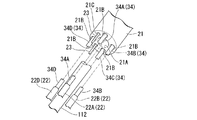
図4Aおよび図4Bは、第一アーム20Aの構成を示す斜視図である。なお、第一アーム20Aの構成を分かりやすくするため、図4Aおよび図4Bにおいては一部の構成の図示を省略している。
図4Aに示すように、第一アーム20Aは、筒状に形成されたアーム本体部21と、アーム本体部21の先端に設けられたアーム先端部30と、アーム本体部21の基端に設けられたアーム操作部40と、を備えている。
図4Bに示すように、アーム本体部21は、処置具110を挿通するための処置具ルーメン21Aが、アーム本体部21の中央部を貫通して長手方向に延びて形成されている。さらに、アーム本体部21において処置具ルーメン21Aの径方向外側には、アーム本体部21を貫通して長手方向に延びた4つの伝達部材挿通孔部21Bと、2つの第二操作ワイヤ挿通孔部21Cとが形成されている。
処置具ルーメン21Aは、処置具110の処置部111および挿入部112が進退自在な貫通孔であり、アーム本体部21の長手方向に対して直交する面内における断面形状は円形になっている。
4A and 4B are perspective views showing the configuration of the
As shown in FIG. 4A, the
As shown in FIG. 4B, the arm
The
伝達部材挿通孔部21Bの内部には、アーム操作部40における操作入力をアーム先端部30の後述する第一湾曲部32へ伝達するための伝達部材22が設けられている。
伝達部材22は、棒状のコネクティングロッド(コネクティングロッド22A、コネクティングロッド22B、コネクティングロッド22C、コネクティングロッド22D、以下「コネクティングロッド22A〜22D」と称することがある。)を有し、コネクティングロッド22A〜22Dが4つの伝達部材挿通孔部21Bのそれぞれに進退自在に挿通されている。なお、図4Aおよび図4Bでは、コネクティングロッド22Cは処置具110の挿入部112の奥に隠れているので図示されていない。
Inside the transmission
The
第二操作ワイヤ挿通孔部21Cの内部には、アーム操作部40における操作入力をアーム先端部30の後述する第二湾曲部35へ伝達するための第二操作ワイヤ23が設けられている。
本実施形態では、第二操作ワイヤ23は2本設けられている。2本の第二操作ワイヤ23は、2つの第二操作ワイヤ挿通孔部21Cのそれぞれに進退自在に挿通されている。また、第二操作ワイヤ23の先端は、後述するアーム先端部30の第二湾曲部35に固定されている。本実施形態では第二操作ワイヤ23が2本設けられているので、第二操作ワイヤ23の1本あたりにかかる牽引力量を軽減することができる。このため、第二操作ワイヤ23が牽引されたときの第二操作ワイヤ23の伸びによる牽引力量の損失や後述する第二湾曲部35のぶれなどを低減することができる。
Inside the second operation wire
In the present embodiment, two
アーム先端部30は、処置具110の処置部111が繰り出される先端硬質部31と、先端硬質部31の基端側に設けられた第一湾曲部32と、第一湾曲部32の基端側に設けられた第二湾曲部35とを有している。
The arm
先端硬質部31は、処置具110の処置部111を挿通可能な処置部ルーメン31Aを有する略筒状に形成されている。先端硬質部31は、第一湾曲部32および第二湾曲部35と異なり湾曲しないようになっている。
The distal end
第一湾曲部32および第二湾曲部35には、複数の節輪(第一節輪33、第二節輪36)がアーム先端部30の軸線方向に並んで整列するように連結されている。本実施形態では、第一節輪33と第二節輪36とは、第一節輪33が相対的に先端側で、第二節輪36が相対的に基端側に配置されている。第一節輪33および第二節輪36の形状は、リング状になっており、第一湾曲部32および第二湾曲部35に挿通された処置具110の処置部111は、第一節輪33および第二節輪36の内部を通じて先端硬質部31から繰り出されるようになっている。
A plurality of node rings (a
詳細は図示していないが、第一湾曲部32の第一節輪33の先端には、第一湾曲部32を湾曲動作させるためのアングルワイヤ部(伝達部材)34の先端が固定されている。アングルワイヤ部34は、図4Bに示すように、4本のアングルワイヤ(アングルワイヤ34A、アングルワイヤ34B、アングルワイヤ34C、アングルワイヤ34D、以下「アングルワイヤ34A〜34D」と称することがある。)からなる。アングルワイヤ34A〜34Dの先端は、第一節輪33の先端に、周方向に90度離間してそれぞれ固定されている。アングルワイヤ34A〜34Dの基端は、コネクティングロッド22A〜22Dの先端にそれぞれ接続されている。
Although not shown in detail, the tip of an angle wire portion (transmission member) 34 for bending the
なお、コネクティングロッド22A〜22Dとアングルワイヤ34A〜34Dとの接続箇所は、第二湾曲部35よりも基端側で、かつアーム本体部21の先端側に位置していることが好ましい。これは、硬質なコネクティングロッド22A〜22Dによって、第一湾曲部32を湾曲させる力量を効率よく伝達させるためである。
In addition, it is preferable that the connection location of the connecting
アーム操作部40は、伝達部材22およびアングルワイヤ部34、あるいは第二操作ワイヤ23を牽引操作することで、第一湾曲部32あるいは第二湾曲部35をそれぞれ湾曲動作させるためのものである。アーム操作部40は、第一湾曲部32を湾曲動作させるための第一湾曲操作部50と、第二湾曲部35を湾曲動作させるための第二湾曲操作部60と、第一湾曲操作部50および第二湾曲操作部60が連結されているとともにアーム本体部21の基端に固定された操作本体41と、を有している。
The
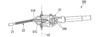
図5は、処置システム100の一部の構成を示す斜視図で、第一湾曲操作部50を説明するために一部の構成の図示を省略した図である。また、図6は、第一湾曲操作部50を示す平面図である。
図5および図6に示すように、第一湾曲操作部50は、伝達部材22に一端が連結された4本のリンク(リンク51A、リンク51B、リンク51C、およびリンク51D)を有するリンク部51と、リンク部51のうちリンク51Aおよびリンク51Cの他端が連結されたスライダーリンク部52と、スライダーリンク部52が進退自在に支持されているとともに、リンク部51のうちリンク51Bおよびリンク51Dの他端が連結された回動部材53と、回動部材53に連結されて基端側に向かって延びて設けられた筒状の操作レバー58とを備えている。
FIG. 5 is a perspective view showing a configuration of a part of the
As shown in FIGS. 5 and 6, the first
スライダーリンク部52は、棒状の第一スライダー52Aと棒状の第二スライダー52Bとを有しており、第一スライダー52Aおよび第二スライダー52Bにおいてリンク51Aおよびリンク51Cが連結された側と反対の端部は、操作レバー58の後述する接続部59に接続されている。
The
回動部材53には、スライダーリンク部52の棒状の第一スライダー52Aと棒状の第二スライダー52Bとが進退自在に挿通可能な貫通孔53Aおよび貫通孔53Bが形成されている。また、回動部材53は、後述する操作本体41に連結される回動軸部54、第一ガイドピン55および第二ガイドピン56と、円弧の一部をなして形成された上下動ガイド57とを有している。
The turning
回動軸部54は、回動部材53から互いに外向きに突出して2箇所に形成されている。回動軸部54の中心軸線は、回動部材53を回動させるための第二回動中心O2になっている。また、第二回動中心O2は、第一湾曲部32が湾曲されていない状態では、リンク51Aおよびリンク51Cとスライダーリンク部52との連結部を通るようになっている。
The
第一ガイドピン55と第二ガイドピン56とは、回動軸部54が延びる方向と同方向に互いに平行に延びて形成されており、回動部材53の外面から突出して形成されている。
The
上下動ガイド57には、円弧状に回動部材53がくりぬかれた貫通孔57Aが形成されている。貫通孔57Aは、円弧の中心が操作レバー58を上下方向に揺動させるときの揺動の中心になるように形成されている。
The
操作レバー58は、処置具110の挿入部112を挿入するための処置具挿入口58Cが形成された筒状部材で、回動部材53に連結された接続部59と、回動部材53よりも基端側に向かって延びる筒状の把持部58Dとを有している。
処置具挿入口58Cの先端側は回動部材53の内部に開口しており、処置具挿入口58Cを通じて挿入された処置具110は、回動部材53の内部の空洞部を通って、アーム本体部21の処置具ルーメン21Aに挿入されるようになっている。
The
The distal end side of the treatment
図7は処置システム100の一部の構成を示す分解斜視図で、第一湾曲操作部50を説明するために一部の構成の図示を省略している。図7に示すように、接続部59は、回動部材53に設けられた上下動ガイド57に形成された貫通孔57Aの内壁にベアリングを介して接する上下動ガイドピン59Aと、上下動ガイドピン59Aと上下動ガイド57との間に介在される摺動部材F1とを有している。
FIG. 7 is an exploded perspective view showing a part of the configuration of the
摺動部材F1は、上下動ガイドピン59Aのそれぞれに対してひとつずつ設けられており、例えば弾性を有する材料によって形成することができる。
さらに、接続部59には、スライダーリンク部52の第一スライダー52Aおよび第二スライダー52Bにピンを介して連結するためのスライダー連結孔部59Bが形成されている。スライダー連結孔部59Bは接続部59に2箇所形成され、それぞれの形状は長孔形状になっている。
One sliding member F1 is provided for each of the vertical movement guide pins 59A, and can be formed of an elastic material, for example.
Further, the connecting
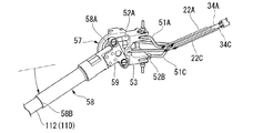
図8Aおよび図8Bは、処置システム100の一部の構成を示す斜視図で、第二湾曲操作部60を説明するために一部の構成を省略している。また、図9Aおよび図9Bは、処置システム100の一部の構成を示す平面図で、第二湾曲操作部60を説明するために一部の構成を省略している。
8A and 8B are perspective views showing a partial configuration of the
図8Aないし図9Bに示すように、第二湾曲操作部60は、一端61Aが回動部材53の回動軸部54に回動自在に連結された連結棒61と、連結棒61と操作本体41とを連結して連結棒61を操作本体41に対して位置決めする位置決め部62と、連結棒61の他端61Cが嵌合する牽引ガイド部67とを有している。
As shown in FIGS. 8A to 9B, the second
図8Aおよび図8Bに示すように、連結棒61は、一端61Aと他端61Cとの間に、操作本体41の後述するガイドプレート43Aに向かう方向に延びて形成された貫通孔61Bを有している。なお、貫通孔61Bと他端61Cとの間に形成された貫通孔は、連結棒61を軽量化するための肉抜き部である。
図9Aに示すように、連結棒61の他端61Cには、第二操作ワイヤ23の基端が固定されている。
As shown in FIGS. 8A and 8B, the connecting
As shown in FIG. 9A, the proximal end of the
図8Aおよび図8Bに示すように、位置決め部62は、操作本体41の後述するガイドプレート43Aに形成された窪み49Aおよび貫通孔49Bに係合する位置決めピン63と、位置決めピン63を支持し、位置決めピン63よりも大径に形成されたピンレバー64とを有している。
As shown in FIGS. 8A and 8B, the
位置決めピン63には、先端が半球形状をなす先端係合部63Aと、貫通孔61Bを貫通して延びてピンレバー64に固定される軸部63Bとが形成されている。
The
ピンレバー64は、連結棒61の貫通孔61Bに挿入されて固定された略筒状の固定部65と、固定部65の内部で位置決めピン63を操作本体41側へ付勢するコイルばね65Aと、固定部65の外周面に嵌合するとともに位置決めピン63の軸部63Bに固定されたピン操作部66と、ピン操作部66の内部に設けられた皿ばね部66Aとを有している。
The
また、ピンレバー64と固定部65とには、皿ばね部66Aによって位置決めピン63を操作本体41側へ付勢する付勢力を調整するための一組のネジ部64Aが形成されている。ネジ部64Aにより、固定部65に対してピン操作部66を軸回りに回転させて位置決めピン63が貫通孔49Bから抜けにくくすることができる。
The
図9Aおよび図9Bに示すように、牽引ガイド部67は、連結棒61の動作方向を第二操作ワイヤ23の牽引方向に変換するカムとなる貫通孔68を有している。貫通孔68は、第二操作ワイヤ23の基端が延びる方向に長い長孔になっており、連結棒61の他端61Cは、貫通孔68の一端68Aと他端68Bとの間で往復動作できるようになっている。
As shown in FIGS. 9A and 9B, the
また、上述の位置決め部62によって位置決めピン63が貫通孔49Bに挿入されている状態では、牽引ガイド部67の貫通孔68の他端68Bに連結棒61の他端61Cが位置しており、このとき、第二操作ワイヤ23の基端が延びる方向と連結棒61の長手軸の方向は略一致するようになっている。この位置関係では、いわゆるトグル機構(倍力機構)によって、第二操作ワイヤ23の牽引状態が保持されるように、連結棒の強度の範囲内で第二操作ワイヤ23を拘束することができるようになっている。第二湾曲操作部60に上述のトグル機構が採用されていることで、第二湾曲部35を湾曲動作させるために第二操作ワイヤ23を牽引するときに、第二操作ワイヤ23に対して十分な牽引力量を軽い力で加えることができる。
In the state where the
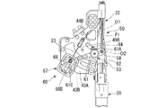
図10Aおよび図10Bは、処置システム100の一部の構成を示す斜視図で、操作本体41を説明するために一部の構成の図示を省略している。
操作本体41は、アーム本体部21に固定された先端連結部42と、先端連結部42に固定された略板状のガイドプレート43Aおよびガイドプレート43Bとを有している。
10A and 10B are perspective views showing a part of the configuration of the
The operation
先端連結部42には、アーム本体部21に形成された処置具ルーメン21A、伝達部材挿通孔部21B、および第二操作ワイヤ挿通孔部21C(いずれも図4B参照)に連通する貫通孔が形成されている。
The distal
ガイドプレート43Aとガイドプレート43Bとは、先端側が先端連結部42に固定されており、ガイドプレート43Aとガイドプレート43Bとは面方向が互いに平行になるように対向して配置されている。ガイドプレート43Aには、ガイドプレート43Aの厚さ方向にガイドプレート43Aを貫通してくりぬかれた形状の第一案内溝44および第二案内溝45が形成されている。
さらに、ガイドプレート43Aには、図8Bに示す第二湾曲操作部60に設けられた位置決め部62の位置決めピン63が係合する位置決め孔部49が設けられている。位置決め孔部49には、ガイドプレート43A上に形成された窪み49Aと、ガイドプレート43Aを厚さ方向に貫通して形成された貫通孔49Bとが設けられている。
The
Further, the
窪み49Aの形状は、上述の位置決めピン63(図8B参照)の先端係合部63Aが嵌合する略半球形状になっている。また、窪み49Aの形状は、ガイドプレート43Aの厚さ方向に直交する方向に向かって位置決めピン63を押圧したときに先端係合部63Aと窪み49Aとの係合を外すことができるような形状になっていることが好ましい。具体的には、ガイドプレート43Aの表面に開口する開口端部の形状が、ガイドプレート43Aの厚さ方向に対して傾斜されていることが好ましい。
なお、詳細は図示しないが、ガイドプレート43Bは、ガイドプレート43Aの面方向を基準として面対称な形状に形成されている。
The shape of the
Although not shown in detail, the
図11Aは、処置システム100の一部の構成を示す平面図で、アーム操作部40の操作本体41をガイドプレート43A側からガイドプレート43B側へ向かってみたときの平面図である。また、図11Bは図11Aの一部を拡大して示す拡大図である。
FIG. 11A is a plan view showing a partial configuration of the
図11Aに示すように、第一案内溝44は、回動部材53の回動軸部54を案内するための一対の壁部44Aを有している。一対の壁部44Aの形状は、ガイドプレート43Aの厚さ方向から壁部44Aを見たときの輪郭線が円弧の一部をなすように湾曲した湾曲面になっている。また、ガイドプレート43Aとガイドプレート43Bとのそれぞれに形成された一対の壁部(図10A参照)における円弧の中心を通る直線は、回動部材53および操作レバー58が回動する第一回動中心O1である。本実施形態では、第一回動中心O1の位置は、アーム先端部30において第一湾曲部32が中立状態(湾曲していない状態、図2参照)であるときのアーム操作部40をガイドプレート43Aの厚さ方向から見たときに、コネクティングロッド22A、22Cとリンク51A、51Cとの連結部Cに重なる位置になっている。
As shown in FIG. 11A, the
図9Aおよび図9Bに示すように、先端連結部42と、ガイドプレート43A、43Bと、回動部材53と、操作レバー58とが組みつけられている状態で、上述の回動部材53は、操作レバー58の長手軸の方向とアーム本体部21に挿通された伝達部材22が延びる方向とが一致する第一位置P1と、操作レバー58の長手軸の方向と伝達部材22が延びる方向とが交差し、回動軸部54が第一案内溝44の端部44Bに接触する第二位置P2との間で、回動部材53の回動軸部54が第一案内溝44の壁部44Aに案内されて第一回動中心O1回りに旋回動作するようになっている。
As shown in FIGS. 9A and 9B, in the state where the
さらに、図9Aおよび図10Aに示すように、上述の位置決め部62によって連結棒61が貫通孔49Bの位置に位置決めされたときには、連結棒61の他端61Cが牽引ガイド部67に支持されるとともに貫通孔61Bは貫通孔49Bと重なる位置に位置決めされ、連結棒61の一端61Aは第一案内溝44の端部44Bの位置に位置決めされて固定される。このとき、上述の回動部材53は、回動軸部54が第一案内溝44の端部44Bにある状態で、回動軸部54を第二回動中心O2として第二回動中心O2回りに揺動するようになっている。
Further, as shown in FIGS. 9A and 10A, when the connecting
図10Aおよび図10Bに示すように、第二案内溝45は、第一案内溝44の円弧の径方向外側に形成され、相対的に第一回動中心O1に近い側に位置する内壁部46と、相対的に第一回動中心O1から遠い側に位置する外壁部47とを有している。
As shown in FIGS. 10A and 10B, the
第二案内溝45には、回動部材53の第一ガイドピン55および第二ガイドピン56が挿入されている。また、第一ガイドピン55および第二ガイドピン56と第二案内溝45との間には、ガイドプレート43A、43Bの外面に接する摺動部材F2が設けられている。摺動部材F2は、弾性を有し、第一ガイドピン55および第二ガイドピン56によってガイドプレート43Aに押し付けられている。
The
図11Aおよび図11Bに示すように、内壁部46の形状は、ガイドプレート43Aの厚さ方向から内壁部46を見たときの輪郭線が曲線をなすように湾曲した湾曲面になっている。内壁部46は、ガイドプレート43A側からガイドプレート43B側へ向かってアーム操作部40を見て、第一回動中心O1回りに反時計回りに回動部材53を回動させるときに、回動部材53の第一ガイドピン55の外周面を押圧して回動部材53を案内するようになっている。
As shown in FIGS. 11A and 11B, the shape of the
本実施形態では、回動部材53の回動軸部54は第一案内溝44の壁部44Aに接触し、かつ回動部材53の第一ガイドピン55は第二案内溝45の内壁部46に接触してそれぞれ案内されるようになっている。
内壁部46と第一案内溝44との間の距離は、回動部材53における回動軸部54と第一ガイドピン55との間の間隔Wよりも短くなっている。また、図9Aおよび図11Aに示すように、第一位置P1に操作レバー58が位置するときにおける回動軸部54と第一ガイドピン55との間の距離L1よりも、第二位置P2に操作レバー58が位置するときにおける回動軸部54と第一ガイドピン55との間の距離L2を漸次大きくするように、内壁部46と第一案内溝44との間の距離が設定されて第二案内溝45は形成されている。なお、内壁部46と第一案内溝44との間の距離の最大値は、回動部材53における回動軸部54と第一ガイドピン55との間の間隔Wの大きさと略等しくなっている。
In the present embodiment, the
The distance between the
図10Aないし図11Bに示すように、外壁部47の形状は、ガイドプレート43Aの厚さ方向から内壁部46を見たときの輪郭線が曲線をなすように湾曲した湾曲面になっている。外壁部47は、ガイドプレート43A側からガイドプレート43B側へ向かってアーム操作部40を見て、第一回動中心O1回りに時計回りに回動部材53を回動させるときに、回動部材53の第二ガイドピン56を押圧して回動部材53を案内するようになっている。
As shown in FIGS. 10A to 11B, the shape of the
また、第二案内溝45において第一位置P1と反対側の端部P3には、内壁部46および外壁部47とは形状が異なって形成された逃げ部48が設けられている。逃げ部48は、内壁部46よりも第一案内溝44側に窪んで形成されている。
以上に説明した構成の、本実施形態の処置システム100の使用時の動作について、マニピュレータ1の動作を中心に、図12ないし図24を参照して説明する。
Further, in the
With reference to FIGS. 12 to 24, the operation of the
図12は、処置システム100を使用時の形態に組み立てる動作を説明するための動作説明図である。図12に示すように、処置システム100を使用するときには、まず、操作者は、挿入部10のチャンネル12に第一アーム20Aを挿通し、チャンネル13に、第二アーム20Bを挿通する。このとき、第一アーム20Aおよび第二アーム20Bのアーム操作部40においては、操作レバー58が第一位置P1側に移動された状態にする。操作レバー58が第一位置P1側にあるときには、第一湾曲操作部50においては、上下動ガイド57の貫通孔57Aの中間部に上下動ガイドピン59Aが位置するように操作レバー58を位置あわせする(図5、図20Aおよび図20B参照)。これにより、第一湾曲操作部50に連結された伝達部材22は、第一湾曲部32が湾曲されていない直線状の中立位置に位置する。
FIG. 12 is an operation explanatory diagram for explaining the operation of assembling the
また、操作レバー58が第一位置P1側にあるときには、第二湾曲操作部60においては、連結棒61の他端61Cが牽引ガイド部67の貫通孔68の一端68Aに位置しており、連結棒61の他端61Cに連結されている第二操作ワイヤ23は牽引されていない(図9Aおよび図9B参照)。このため、第二湾曲部35は自身の復元力によって直線状態になる。
したがって、第一湾曲部32、第二湾曲部35、およびアーム本体部21は直線状になる。操作者は、この状態で、第一アーム20A、第二アーム20Bをそれぞれチャンネル12、チャンネル13へ先端硬質部31側から挿入する。
When the
Therefore, the
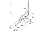
図13は、処置システム100の使用時の一過程を示す動作説明図である。図13に示すように、操作者は、例えば患者の腹壁に小切開を加え、処置システム100の挿入部10を挿通可能なトラカール70を挿入する。操作者は、必要に応じて気腹等を行ってから、トラカール70を介して処置システム100をアーム先端部30側から体腔内へ挿入する。このとき、挿入部10のチャンネル11に内視鏡130の挿入部133を挿入し、撮像部131をアーム先端部30に沿わせて直線状にし、撮像部131によって撮像される画像を見ながら体腔内の処置対象部位までアーム先端部30を案内する。
FIG. 13 is an operation explanatory diagram illustrating one process when the
図14は、処置システム100の使用時の一過程を示す動作説明図である。図14に示すように、処置対象までアーム先端部30が案内されたら、操作者は、操作レバー58の処置具挿入口58Cを通じて処置具110、120を体腔内へ挿入する。
操作レバー58が第一位置P1側に位置しているときには、操作レバー58とアーム本体部21とが同軸状に揃っている。また、第一湾曲部32および第二湾曲部35は湾曲されておらず直線状である。従って、操作レバー58が第一位置P1側にあるときには、操作レバー58の処置具挿入口58Cからアーム先端部30の先端硬質部31に至るまでの、処置具110、120の挿入部112、122を挿通するための管路が直線状になっている。
このため、操作レバー58の処置具挿入口58Cから挿入された処置部111は、操作レバー58、回動部材53、アーム本体部21、アーム先端部30の内部をこの順で通って先端硬質部31の先端から繰り出される。処置具120についても同様に先端硬質部31の先端から繰り出される。
FIG. 14 is an operation explanatory diagram illustrating a process during the use of the
When the
Therefore, the
図15Aないし図15Cは、処置システム100の使用時の一過程を示す動作説明図である。図15Aに示すように、操作者は、操作レバー58が第一位置P1側にある初期状態から、操作レバー58を操作本体41に対して相対移動させ、回動部材53の回動軸部54を第一回動中心O1回りに旋回動作させる。操作レバー58が第一位置P1にあるときには、位置決め部62における位置決めピン63の先端係合部63A(図8B参照)がガイドプレート43Aの窪み49Aに嵌合しているが、窪み49Aが略半球状であるので、操作レバー58を回動させるように力を加えることで、ピン操作部66に触れなくても先端係合部63Aと窪み49Aとの嵌合を外すことができる。すると、図15Bに示すように回動軸部54は第一案内溝44内へ進入する。
FIG. 15A to FIG. 15C are operation explanatory views showing one process when the
図15Bおよび図15Cに示すように、第一案内溝44の端部44Bに回動軸部54が移動したときには、リンク部51のリンク51Aおよびリンク51Cは、第一回動中心O1回りに回動する。したがって、第一回動中心O1回りに回動部材53を回動させても、第一位置P1から第二位置P2までの間では、コネクティングロッド22Aおよびコネクティングロッド22Cは移動しない。その結果、コネクティングロッド22Aおよびコネクティングロッド22Cにアングルワイヤ34Aおよびアングルワイヤ34Cを介して接続された第一節輪33は牽引されず、第一湾曲部32は上下方向には湾曲しない。
As shown in FIGS. 15B and 15C, when the
図16Aないし図16Cは、操作レバー58を第一位置P1側から第二位置P2側へ移動させるときの第一湾曲操作部50の動作原理を示す説明図である。なお、図16Bは、回動部材53が第二回動中心O2回りに回動しない場合の第一湾曲操作部50の位置関係を説明するための説明図であって、本実施形態の処置システム100において操作レバー58を第一位置P1側から第二位置P2側へ移動させる動作を行うときの実際の動作を表す図ではない。
また、図16Aないし図16Cに符号L1、L2で示す線は、操作レバー58が第一位置P1にあるときの各コネクティングロッドの先端と基端の位置を示している。
FIG. 16A to FIG. 16C are explanatory views showing the operation principle of the first
16A to 16C indicate the positions of the distal end and the proximal end of each connecting rod when the
図16Aに示す第一位置P1から図16Cに示すように操作レバー58が第二位置P2に向かって移動されているときには、回動部材53は、第一ガイドピン55および第二ガイドピン56が第二案内溝45の内壁部46および外壁部47に案内されることで、ガイドプレート43A側からガイドプレート43B側に向かってみたときに第二回動中心O2回りに反時計回りに回動している。このとき、ガイドプレート43A側からガイドプレート43B側に向かってみたときに第一回動中心O1回りに時計回りに回動部材53が回動することでリンク51Bを介してコネクティングロッド22Bが牽引される牽引量(図16B参照)と、ガイドプレート43A側からガイドプレート43B側に向かってみたときに第二回動中心O2回りに反時計回りに回動部材53が回動することでリンク51Bを介してコネクティングロッド22Bが押し出される押し出し量とは等しく設定されている。その結果、第一回動中心O1回りに回動部材53を時計回りに回動させても、第一位置P1から第二位置P2までの間では、コネクティングロッド22Bはアーム本体部21の内部で進退動作しない。
When the
同様に、ガイドプレート43A側からガイドプレート43B側に向かってみたときに第一回動中心O1回りに時計回りに回動部材53が回動することでリンク51Dを介してコネクティングロッド22Dが押し出される押し出し量(図16B参照)と、ガイドプレート43A側からガイドプレート43B側に向かってみたときに第二回動中心O2回りに反時計回りに回動部材53が回動することでリンク51Dを介してコネクティングロッド22Dが牽引される牽引量とは等しく設定されている。その結果、第一回動中心O1回りに回動部材53を回動させても、第一位置P1から第二位置P2までの間では、コネクティングロッド22Dはアーム本体部21の内部で進退動作しない。
従って、第一回動中心O1回りに回動部材53を回動させても、第一位置P1から第二位置P2までの間では、コネクティングロッド22B、22Dは進退動作せず、コネクティングロッド22Bおよびコネクティングロッド22Dにアングルワイヤ34Bおよびアングルワイヤ34Dを介して接続された第一節輪33は牽引されず、第一湾曲部32は左右方向には湾曲しない。
Similarly, when viewed from the
Therefore, even if the
このように、第一位置P1から第二位置P2まで第一回動中心O1回りに回動部材53をさせても、第一湾曲部32は湾曲されず直線状の形状が維持される。
このとき、アーム操作部40においては、伝達部材22の長手軸に平行で第一回動中心O1を通る直線Xに対する操作レバー58の先端58Aのなす角の大きさθ1と、直線Xに対する操作レバー58の基端58Bのなす角の大きさθ2とは、θ1>θ2になっている。すなわち、操作レバー58を回動させたときには、回動部材53が第一回動中心O1回りに回動すると同時に回動部材53が第二回動中心O2回りに逆方向に回動するので、操作レバー58の基端58Bは操作レバー58の先端58Aよりも遅れて回動する。
As described above, even if the
At this time, in the
一方、図15Bおよび図15Cに示すように、操作レバー58を第一位置P1側から第二位置P2側へと移動させると、回動部材53の回動軸部54によって連結棒61が第二位置P2側へと移動される。すると、連結棒61の他端61Cは牽引ガイド部67の貫通孔68に沿って一端68Aから他端68Bへと移動する。これにより、連結棒61の他端61Cに固定された第二操作ワイヤ23は、貫通孔68の他端68B側へと牽引される。
On the other hand, as shown in FIGS. 15B and 15C, when the operating
図17Aおよび図17Bは、処置システム100の使用時の動作を示す斜視図で、アーム先端部30の近傍を拡大して示している。
図15Aないし図15Cに示したように第二操作ワイヤ23が連結棒61によって牽引されると、図17Aおよび図17Bに示すように、第二操作ワイヤ23の先端に連結された第二湾曲部35が湾曲される。第一アーム20Aと第二アーム20Bとに設けられた第二湾曲部35が湾曲動作されると、アーム先端部30において第一湾曲部32および処置部111、121の距離が通常時より離間した手技のしやすい状態(以下、当該状態を「トライアンギュレーション(tri-angulation)」と称する。)になる。
17A and 17B are perspective views showing the operation of the
When the
第一アーム20Aと第二アーム20Bとのそれぞれにおいて、第二節輪36に先端が固定された第二操作ワイヤ23は、図9Aおよび図9Bを参照してすでに説明したように、第二湾曲操作部60のトグル機構によってアーム操作部40側に牽引された状態で支持され、位置決め部62によって操作本体41のガイドプレート43A、43Bに固定される。必要に応じて、操作者は、図8Bに示す位置決め部62のピン操作部66を固定部65に対して軸回りに回転させて、位置決めピン63が貫通孔49Bから抜けないようにしてもよい。この場合、処置部111、121を使用した処置の最中に第二湾曲部35や操作レバー58がずれることを抑制できる。
In each of the
このように、第一位置P1から第二位置P2へ操作レバー58を移動させるだけで、処置具110および処置具120を操作しやすく処置具110、120の操作部113、123が互いにぶつからないV字状に操作レバー58を配置するとともに、アーム部20は、図17Aに示す初期の位置関係から、図17Bに示すトライアンギュレーションの状態に変形する。
In this way, it is easy to operate the
以下では、トライアンギュレーションの状態で、第一湾曲部32を湾曲させる動作について説明する。まず、第一湾曲部32を左右に湾曲させる動作について図18ないし図19Cを参照して説明する。
図18は、トライアンギュレーションの状態で、第一湾曲部32を湾曲させる動作を説明するための動作説明図である。図18に示すように、操作者は、操作レバー58が第二位置P2にある状態から、操作レバー58を例えば端部P3側、あるいは第一位置P1側へと移動させることができる。このとき、回動軸部54は第一案内溝44の端部44Bに位置決めされているので、回動軸部54は第一回動中心O1回りに回動することはできない。一方で、回動部材53は、回動軸部54の中心軸線である第二回動中心O2回りには回動することができる。回動部材53が第二回動中心O2回りに例えば第一位置P1側へ移動する場合には、第一ガイドピン55および第二ガイドピン56は第一位置P1側へ移動され、回動部材53は、第二案内溝45の内壁部46と外壁部47との間で所定の範囲で揺動することができる。また、回動部材53が第二回動中心O2回りに例えば端部P3側へ移動する場合には、第一ガイドピン55および第二ガイドピン56は端部P3側へ移動され、逃げ部48に沿って、あるいは逃げ部48の内部で所定の範囲で移動できる。
Below, the operation | movement which curves the
FIG. 18 is an operation explanatory diagram for describing an operation of bending the
図19Aないし図19Cは、回動部材53を第二回動中心O2回りに回動動作させたときの第一アーム20Aの動作を説明するための動作説明図である。例えば図19Bに示すように、回動部材53を第二回動中心O2回りに端部P3(図18参照)側へ回動させると、リンク部51においては、リンク51A、51Cは動作せず、リンク51Bは牽引され、リンク51Dは押し出される。これにより、コネクティングロッド22Bによってアングルワイヤ34Bが牽引され、アングルワイヤ34Bによって第一湾曲部32が図19Bに示す平面視で右方向に湾曲動作される。同様に、図19Cに示すように、回動部材53を第二回動中心O2回りに第一位置P1(図18参照)側へ回動させると、第一湾曲部32は図19Bに示す平面視で左方向に湾曲動作される。
19A to 19C are operation explanatory views for explaining the operation of the
以下では、第一湾曲部32を上下方向に湾曲させる動作について図20Aないし図23を参照して説明する。
図20Aないし図22Bは、第一湾曲部32を湾曲させる動作を説明するための動作説明図である。
図20Aおよび図20Bに示すように、第一湾曲部32を上下方向に湾曲させない中立状態にするときには、リンク51Aと第一スライダー52Aとの接続部分とリンク51Cと第二スライダー52Bとの接続部分とがともに第二回動中心O2上にあるように、操作レバー58をスライダーリンク部52の第一スライダー52Aおよび第二スライダー52Bの軸方向と平行な方向にあわせる。このとき、上下動ガイドピン59Aと接続部59とによって摺動部材F1を介して上下動ガイド57が挟まれているので、操作レバー58に挿入された処置具110、120や操作レバー58から手を離しても回動部材53に対する操作レバー58の相対位置は維持される。
Below, the operation | movement which curves the
20A to 22B are operation explanatory views for explaining the operation of bending the
As shown in FIGS. 20A and 20B, when the
図21Aおよび図21Bに示すように、第一湾曲部32を下方向に湾曲させるためには、操作レバー58の先端側が相対的に下側になるように操作レバー58の基端を引き上げる。すると、第一スライダー52Aが先端側へ押し込まれ、第二スライダー52Bが基端側へ引き出される。これにより、リンク51Aを介してコネクティングロッド22Aが先端側へ押し出され、リンク51Cを介してコネクティングロッド22Cが基端側へ引き出される。すると、アーム先端部30では、コネクティングロッド22Cの先端に固定されたアングルワイヤ34Cが牽引されて第一湾曲部32が下方向に湾曲する。
As shown in FIGS. 21A and 21B, in order to bend the
反対に、図22Aおよび図22Bに示すように、第一湾曲部32を上方向に湾曲させるためには、操作レバー58の先端側が相対的に上側になるように操作レバー58の基端を押し下げる。すると、第一スライダー52Aが基端側へ引き出され、第二スライダー52Bが先端側へ押し出され、上述の動作と反対にコネクティングロッド22Aの先端に固定されたアングルワイヤ34Aが牽引されて第一湾曲部32が下方向に湾曲する。
On the other hand, as shown in FIGS. 22A and 22B, in order to bend the
以上、第一アーム20Aにおける第一湾曲部32、第二湾曲部35の湾曲操作について説明したが、第二アーム20Bにおいても同様に第一湾曲部32および第二湾曲部35を湾曲操作することができる。すると、図23に示すように、第一アーム20Aと第二アーム20Bとを用いて処置具110、120の処置部111、121を使用する処置を行うことができる。
なお、処置対象を観察しやすくするために、図23に示すように内視鏡130の湾曲部132を湾曲させて撮像部131の視野の向きを適宜変更することもできる。
The bending operation of the
In addition, in order to make it easy to observe the treatment target, the direction of the visual field of the
ところで、処置対象に対する処置をしている最中で、処置具110、処置具120と異なる処置具をアーム部20に取り付けて使用する場合がある。この場合には、第一アーム20Aと第二アーム20Bとのいずれかあるいは両方から処置具を取り外す操作を行う。
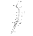
By the way, there is a case where a treatment tool different from the
図24は、処置システム100の使用時にマニピュレータ1から処置具110を取り外す動作を説明するための動作説明図である。処置具110をマニピュレータ1から取り外すときには、マニピュレータ1に処置具110を取り付けた動作と逆順に、図15C、図15B、および図15Aに示すように、操作レバー58を第二位置P2側から第一位置P1側へと移動させる。すると、回動部材53は第一案内溝44および第二案内溝45に案内されて、第一回動中心O1回りに第一位置P1側へ回動されるとともに第二回動中心O2回りに第二位置P2側へ回動される。これにより、図24に示すように、操作レバー58は処置具110を挿入するときと同じ直線状の位置に移動し、第二湾曲部35の湾曲は解除されてトライアンギュレーションの状態から直線状の位置関係に戻る。操作者は、この状態で処置具110を抜去し、他の処置具を挿入して同様に使用することができる。
FIG. 24 is an operation explanatory diagram for explaining an operation of removing the
従来、体腔内に挿入される硬質な挿入部と、挿入部の内部に挿入されるアーム部とを備え、アーム部の内部に挿入される処置具を用いて体腔内で処置を行う処置システムが知られている。
このような従来の処置システムでは、処置システムに取り付けられて使用される処置具は、牽引力量を効率的に処置部へ伝達するために、硬性な部分が挿入部の一部に設けられている場合がある。このような処置具を従来の処置システムに取り付けるためには、処置を行うのに適した形状とは異なる直線的な状態に処置システムを変形させて、処置時には処置を行うための形状に変形させる必要がある。
2. Description of the Related Art Conventionally, there is a treatment system that includes a hard insertion portion that is inserted into a body cavity and an arm portion that is inserted into the insertion portion, and performs a treatment in the body cavity using a treatment tool that is inserted into the arm portion. Are known.
In such a conventional treatment system, the treatment tool used by being attached to the treatment system is provided with a rigid portion at a part of the insertion portion in order to efficiently transmit the amount of traction force to the treatment portion. There is a case. In order to attach such a treatment tool to a conventional treatment system, the treatment system is deformed into a linear state different from a shape suitable for treatment, and is transformed into a shape for performing treatment during treatment. There is a need.
従来の処置システムにおいて、例えば、アーム部の先端部が湾曲可能に構成されている場合があり、具体的には、アーム部の先端部の先端側に設けられた第一湾曲部と、第一湾曲部より基端側に設けられた第二湾曲部とを有する場合がある。このようなアーム部を有する処置システムに処置具を取り付けたときに、処置具を操作しやすく、かつ処置具の操作部の操作時に互いの操作部の動作を邪魔しないように操作部を離間させて操作部を位置あわせする場合があるが、この場合に、位置あわせの動作によってアーム部の先端部の一部(例えば第一湾曲部)が湾曲されることで、体腔内で処置具を用いて処置を行うときの初期位置が、処置を行いにくい位置関係になってしまう場合があった。 In the conventional treatment system, for example, the distal end portion of the arm portion may be configured to be bendable. Specifically, the first curved portion provided on the distal end side of the distal end portion of the arm portion, and the first In some cases, the second curved portion may be provided on the proximal end side with respect to the curved portion. When a treatment tool is attached to such a treatment system having an arm part, the operation parts are separated so that the treatment tool is easy to operate and the operation parts of the treatment tool are not disturbed during operation of the treatment tool. In this case, the treatment tool is used in the body cavity by bending a part of the tip of the arm part (for example, the first bending part) by the positioning operation. In some cases, the initial position when the treatment is performed becomes a positional relationship in which the treatment is difficult to perform.
本実施形態の処置システム100およびマニピュレータ1によれば、操作レバー58を回動させる第一回動中心O1と第二回動中心O2とが設定され、操作本体41に形成された第一案内溝44と第二案内溝45とによって第一回動中心O1回りの回動動作と第二回動中心O2回りの回動動作とが合成されて操作レバー58が第一位置P1から第二位置P2へ移動されるので、操作者が操作レバー58を第一位置P1から第二位置P2へ移動させても第一湾曲部32を直線状態に保つことができる。
また、従来の処置システムでは、処置具を使用しやすい向きにセットしても処置システムが処置部を初期位置に維持するためには、処置システムの湾曲操作部において厳密な位置調整をして処置システムを構成する必要があった。
According to the
Further, in the conventional treatment system, in order for the treatment system to maintain the treatment portion at the initial position even when the treatment tool is set in an easy-to-use direction, the treatment operation is performed by strictly adjusting the position of the bending operation portion of the treatment system. The system had to be configured.
本実施形態の処置システム100およびマニピュレータ1によれば、アーム操作部40に形成された第一案内溝44と第二案内溝45とによって第一位置P1と第二位置P2とのそれぞれにおける回動部材53の向きを定めることができるので、伝達部材22およびリンク部51を配置するときの設計上の自由度を高めることができる。
また、従来の処置システムでは、トライアンギュレーションの状態にアームを変形させるために、処置具を使用しやすい位置になるようにセットするのと別の動作でアームを湾曲させる必要があった。
本実施形態の処置システム100およびマニピュレータ1によれば、アーム操作部40に設けられた第二湾曲操作部60が操作レバー58の動作に連動して動作し、操作レバー58が第二位置P2に移動するときに第二操作ワイヤ23を牽引することができるので、処置システム100の取り扱いを簡単にすることができる。
According to the
Further, in the conventional treatment system, in order to deform the arm to the triangulation state, it is necessary to bend the arm by a different operation from the setting of the treatment tool so that it is easy to use.
According to the
さらに、第二湾曲操作部60がトグル機構によって第二操作ワイヤ23を牽引状態で拘束することができるので、第二操作ワイヤ23を牽引するときの牽引力量を大きくすることができる。これにより、アーム部20に処置具110、120を取り付けて体腔内で処置を行うときに第二湾曲部35にねじれなどの外力が伝わっても、第二湾曲部35の湾曲状態を維持してトライアンギュレーションを確保することができる。
Furthermore, since the second
以上、本発明の好ましい実施形態を説明したが、本発明はこれに限定されることはない。本発明の趣旨を逸脱しない範囲で、構成の付加、省略、置換、およびその他の変更が可能である。
たとえば、第一案内溝44および第二案内溝45の形状は、上述の形状に限られるものではない。第一案内溝44および第二案内溝45の形状は、操作レバー58を第一位置P1から第二位置P2に向かって移動させるときに4つのコネクティングロッド22A〜22Dの相対位置が軸方向に前後しないように、例えばシミュレーションなどを行って適宜形状を設計することができる。
As mentioned above, although preferable embodiment of this invention was described, this invention is not limited to this. Additions, omissions, substitutions, and other modifications can be made without departing from the spirit of the present invention.
For example, the shapes of the
また、上述の実施形態では第一回動中心O1の位置を、第一湾曲部32が湾曲されていないときのコネクティングロッド22A、22Cとリンク51A、52Cとの接続部分と一致する位置に設定している例を示したが、これに限らず、第一回動中心の位置は、第一回動中心O1の位置よりも先端側にずれた位置に設定することができる。この場合、第一回動中心O1回りに回動部材53を回動させることで、コネクティングロッド22A〜22Dを、コネクティングロッド22A〜22Dの先端の位置が揃ったまま基端側へ牽引することができる。これにより、第一湾曲部32のアングルワイヤ34A〜34Dのたるみを取り除き、第一湾曲部32が直線状態にあるときに第一湾曲部32の先端側を基端方向へ牽引する力(プリテンション)を掛けることができる。すると、第一湾曲部32における部品間のクリアランスに起因する第一湾曲部32のぐらつきを軽減するとともに、第一湾曲操作部50の操作に対する第一湾曲部32の応答性を高めることができる。
In the above-described embodiment, the position of the first rotation center O1 is set to a position that coincides with the connecting portion between the connecting
この他、本発明は前述した説明によって限定されることはなく、添付のクレームの範囲によってのみ限定される。 In addition, the present invention is not limited by the above description, and is limited only by the scope of the appended claims.
本発明は、体内で処置を行うための医療機器に好適に適用することができる。また、医療用に限られることなく、たとえば工業用マニピュレータに対しても本発明を適用することができる。 The present invention can be suitably applied to a medical device for performing treatment in the body. Further, the present invention is not limited to medical use, but can be applied to, for example, an industrial manipulator.
1 医療用マニピュレータ
10 挿入部
11、12、13、14 チャンネル
20 アーム部
20A、20B アーム
22 伝達部材
32 第一湾曲部
34 アングルワイヤ部(伝達部材)
35 第二湾曲部
40 操作部
41 操作本体
44 第一案内溝
45 第二案内溝
50 第一湾曲操作部
58 操作レバー
60 第二湾曲操作部
DESCRIPTION OF
35
Claims (4)
前記長軸部材の先端に設けられ、互いに離間する方向に移動自在な一対のアーム部と、
前記一対のアーム部の少なくとも一方に設けられた湾曲部と、
前記湾曲部と連結し、前記長手軸方向に沿って前記長軸部材に対して移動自在に設けられ、前記長手軸方向への移動に応じて前記湾曲部の湾曲状態を変化させる第1の伝達部材と、
前記一対のアーム部と連結し、前記長手軸方向に沿って前記長軸部材に対して移動自在に設けられ、前記長手軸方向への移動に応じて前記一対のアーム部を互いに離間する方向に移動させる第2の伝達部材と、
前記第1の伝達部材の基端部及び前記第2の伝達部材の基端部に固定され、前記一対のアーム部を互いに離間させる方向へ移動させるために前記第2の伝達部材を前記長手軸方向へ移動させ、且つ前記湾曲部を湾曲させるために前記第1の伝達部材を前記長手軸方向へ移動させる操作部と、
前記操作部の移動を第1の位置から第2の位置まで案内する第1のガイド部及び前記第2の位置から第3の位置まで案内する第2のガイド部と、
前記第1の位置から前記第2の位置までの前記第1のガイド部による前記操作部の移動操作に応じて、前記第1の伝達部材の基端部の位置を前記長軸部材に対して前記長手軸方向に固定し、且つ前記第2の伝達部材の基端部の位置を前記長軸部材に対して前記長手軸方向に移動させる第1の状態と、前記第2の位置から前記第3の位置までの前記第2のガイド部による前記操作部の移動操作に応じて、前記第2の伝達部材の基端部の位置を前記長軸部材に対して前記長手軸方向に固定し、且つ前記第1の伝達部材の基端部の位置を前記長軸部材に対して前記長手軸方向に移動させる第2の状態と、の両方の状態に互いに案内する案内部材と、
を有する医療用マニピュレータ。 A long shaft member extending in the longitudinal direction;
A pair of arm portions provided at the distal end of the long shaft member and movable in directions away from each other;
A curved portion provided on at least one of the pair of arm portions;
A first transmission that is connected to the bending portion and is movably provided with respect to the long-axis member along the longitudinal axis direction, and changes a bending state of the bending portion according to the movement in the longitudinal axis direction. Members,
The pair of arm portions are coupled to the pair of arm portions, are provided to be movable with respect to the long axis member along the longitudinal axis direction, and the pair of arm portions are separated from each other in accordance with the movement in the longitudinal axis direction. A second transmission member to be moved;
The second transmission member is fixed to the proximal end portion of the first transmission member and the proximal end portion of the second transmission member, and the second transmission member is moved to the longitudinal axis in order to move the pair of arm portions away from each other. An operation unit for moving the first transmission member in the longitudinal axis direction in order to move the first transmission member in a longitudinal direction and to bend the bending unit;
A first guide part that guides the movement of the operation part from a first position to a second position, and a second guide part that guides the operation part from the second position to a third position;
The position of the base end portion of the first transmission member with respect to the long shaft member is changed according to the movement operation of the operation portion by the first guide portion from the first position to the second position. A first state in which the position of the base end portion of the second transmission member is fixed in the longitudinal axis direction and moved in the longitudinal axis direction with respect to the longitudinal axis member, and the first position from the second position. A position of a base end portion of the second transmission member is fixed in the longitudinal axis direction with respect to the long shaft member in accordance with a movement operation of the operation portion by the second guide portion up to a position of 3, And a second member that moves the position of the base end portion of the first transmission member in the longitudinal direction relative to the long shaft member, and a guide member that guides each other in both states;
A medical manipulator having:
前記一対のアーム部の基端側に、前記一対のアーム部を互いに離間させる離間作動部を有する医療用マニピュレータ。 The medical manipulator according to claim 1, wherein
A medical manipulator having a separating operation part for separating the pair of arm parts from each other on a proximal end side of the pair of arm parts.
前記離間作動部は、前記一対のアーム部を互いに離間させる方向に湾曲可能な離間動作用湾曲部である医療用マニピュレータ。 The medical manipulator according to claim 2, wherein
The said separation operation part is a medical manipulator which is a bending part for the separation operation | movement which can bend in the direction which separates a pair of said arm part mutually.
前記操作部が前記第2の位置に移動したときに前記第2の伝達部材の前記長手軸方向への移動をロックするための位置決め機構をさらに有する医療用マニピュレータ。 The medical manipulator according to claim 1, wherein
A medical manipulator further comprising a positioning mechanism for locking movement of the second transmission member in the longitudinal axis direction when the operation unit is moved to the second position.
Applications Claiming Priority (2)
| Application Number | Priority Date | Filing Date | Title |
|---|---|---|---|
| US28521709P | 2009-12-10 | 2009-12-10 | |
| US61/285,217 | 2009-12-10 |
Related Parent Applications (1)
| Application Number | Title | Priority Date | Filing Date |
|---|---|---|---|
| JP2011516594A Division JP4862105B2 (en) | 2009-12-10 | 2010-10-06 | Medical manipulator |
Publications (2)
| Publication Number | Publication Date |
|---|---|
| JP2012040416A JP2012040416A (en) | 2012-03-01 |
| JP4902017B2 true JP4902017B2 (en) | 2012-03-21 |
Family
ID=44145399
Family Applications (2)
| Application Number | Title | Priority Date | Filing Date |
|---|---|---|---|
| JP2011516594A Active JP4862105B2 (en) | 2009-12-10 | 2010-10-06 | Medical manipulator |
| JP2011240521A Expired - Fee Related JP4902017B2 (en) | 2009-12-10 | 2011-11-01 | Medical manipulator |
Family Applications Before (1)
| Application Number | Title | Priority Date | Filing Date |
|---|---|---|---|
| JP2011516594A Active JP4862105B2 (en) | 2009-12-10 | 2010-10-06 | Medical manipulator |
Country Status (5)
| Country | Link |
|---|---|
| US (2) | US8808277B2 (en) |
| EP (1) | EP2430991B1 (en) |
| JP (2) | JP4862105B2 (en) |
| CN (2) | CN102470003B (en) |
| WO (1) | WO2011070846A1 (en) |
Families Citing this family (22)
| Publication number | Priority date | Publication date | Assignee | Title |
|---|---|---|---|---|
| CN103458807B (en) * | 2011-09-08 | 2016-05-18 | 奥林巴斯株式会社 | Multiple degrees of freedom pliers |
| WO2014123207A1 (en) | 2013-02-05 | 2014-08-14 | Olympus Corporation | Medical manipulator |
| EP2967647B1 (en) * | 2013-03-15 | 2019-08-07 | Miret Surgical, Inc. | Surgical laparoscopic system |
| EP2982330B1 (en) * | 2013-03-28 | 2018-12-12 | Olympus Corporation | Treatment tool exchanging device and medical system |
| CN105072973B (en) * | 2013-03-29 | 2018-01-23 | 奥林巴斯株式会社 | Manipulator, arm-and-hand system and method for controlling robot |
| US10206747B2 (en) * | 2013-05-15 | 2019-02-19 | Intuitive Surgical Operations, Inc. | Guide apparatus for delivery of a flexible instrument and methods of use |
| CN103356294B (en) * | 2013-08-07 | 2015-05-20 | 吴开俊 | Auxiliary mechanical arm for soft lens operation |
| WO2015084157A1 (en) * | 2013-12-04 | 2015-06-11 | Fortimedix Surgical B.V. | Access device and assembly comprising such device |
| EP3223734B1 (en) * | 2015-04-22 | 2020-06-10 | Bio-Medical Engineering (HK) Limited | Robotic devices and systems for performing single incision procedures and natural orifice translumenal endoscopic surgical procedures, and methods of configuring robotic devices and systems |
| JP6289755B2 (en) * | 2015-06-18 | 2018-03-07 | オリンパス株式会社 | Medical system |
| CN107709973A (en) * | 2015-07-09 | 2018-02-16 | 奥林巴斯株式会社 | Pigment detection device and pigment detection method |
| US11331154B2 (en) | 2016-01-07 | 2022-05-17 | Intuitive Surgical Operations, Inc. | Telescoping cannula arm |
| CN106388937B (en) * | 2016-09-28 | 2018-12-18 | 西安交通大学 | A kind of adjustable Pneumatic flexible surgical procedure arm of multiple degrees of freedom rigidity |
| WO2018226892A1 (en) * | 2017-06-06 | 2018-12-13 | The Regents Of The University Of California | Multi-catheter flexible robotic system |
| WO2019065581A1 (en) * | 2017-09-28 | 2019-04-04 | 富士フイルム株式会社 | Endoscope |
| WO2019070696A1 (en) * | 2017-10-02 | 2019-04-11 | The Regents Of The University Of California | Steerable catheter flexible robotic system for use with endoscopes |
| CN111246817B (en) * | 2017-11-02 | 2023-06-27 | 奥林巴斯株式会社 | Bending mechanism and medical manipulator |
| CN109464192B (en) * | 2018-12-29 | 2023-11-14 | 黄振宇 | Three-dimensional bending control mechanical arm |
| JP7145982B2 (en) * | 2019-02-07 | 2022-10-03 | オリンパス株式会社 | Endoscope |
| JP7474993B2 (en) | 2019-03-15 | 2024-04-26 | 慶應義塾 | Medical Inner Tubes |
| WO2023100177A1 (en) * | 2021-12-01 | 2023-06-08 | Tamar Robotics Ltd | Dual robotic endoscope configuration for tissue removal |
| CN114469283B (en) * | 2022-03-31 | 2022-07-01 | 真健康(北京)医疗科技有限公司 | Connecting rod type four-freedom-degree puncture needle positioning and guiding device |
Family Cites Families (37)
| Publication number | Priority date | Publication date | Assignee | Title |
|---|---|---|---|---|
| US4919112B1 (en) * | 1989-04-07 | 1993-12-28 | Low-cost semi-disposable endoscope | |
| US5842993A (en) * | 1997-12-10 | 1998-12-01 | The Whitaker Corporation | Navigable ultrasonic imaging probe assembly |
| US7637905B2 (en) * | 2003-01-15 | 2009-12-29 | Usgi Medical, Inc. | Endoluminal tool deployment system |
| US6599265B2 (en) * | 2000-07-05 | 2003-07-29 | Visionary Biomedical, Inc. | Brake assembly for a steerable cathether |
| JP2002306494A (en) * | 2001-04-11 | 2002-10-22 | Olympus Optical Co Ltd | Surgical treating instrument |
| EP3498213A3 (en) * | 2002-12-06 | 2019-07-03 | Intuitive Surgical Operations, Inc. | Flexible wrist for surgical tool |
| DE10324844A1 (en) * | 2003-04-01 | 2004-12-23 | Tuebingen Scientific Surgical Products Gmbh | Surgical instrument with instrument handle and zero point adjustment |
| US7147650B2 (en) * | 2003-10-30 | 2006-12-12 | Woojin Lee | Surgical instrument |
| US7686826B2 (en) * | 2003-10-30 | 2010-03-30 | Cambridge Endoscopic Devices, Inc. | Surgical instrument |
| WO2005055850A1 (en) * | 2003-12-11 | 2005-06-23 | Thk Co., Ltd. | Bending operation member, multi-joint slider link mechanism, actuator, and manipulator |
| JP2005296412A (en) * | 2004-04-13 | 2005-10-27 | Olympus Corp | Endoscopic treatment apparatus |
| US20050272977A1 (en) * | 2004-04-14 | 2005-12-08 | Usgi Medical Inc. | Methods and apparatus for performing endoluminal procedures |
| JP4528136B2 (en) * | 2005-01-11 | 2010-08-18 | 株式会社日立製作所 | Surgical device |
| US8945095B2 (en) * | 2005-03-30 | 2015-02-03 | Intuitive Surgical Operations, Inc. | Force and torque sensing for surgical instruments |
| JP4534004B2 (en) * | 2005-04-07 | 2010-09-01 | 学校法人慶應義塾 | manipulator |
| JP2006288751A (en) * | 2005-04-11 | 2006-10-26 | Olympus Corp | Electric bending endoscopy instrument |
| JP4823597B2 (en) * | 2005-07-25 | 2011-11-24 | オリンパスメディカルシステムズ株式会社 | Medical control device |
| WO2007013350A1 (en) * | 2005-07-25 | 2007-02-01 | Olympus Medical Systems Corp. | Medical controller |
| US7930065B2 (en) * | 2005-12-30 | 2011-04-19 | Intuitive Surgical Operations, Inc. | Robotic surgery system including position sensors using fiber bragg gratings |
| US8721657B2 (en) * | 2006-01-13 | 2014-05-13 | Olympus Medical Systems Corp. | Medical instrument |
| US8617054B2 (en) * | 2006-01-13 | 2013-12-31 | Olympus Medical Systems Corp. | Medical treatment endoscope |
| US8092371B2 (en) * | 2006-01-13 | 2012-01-10 | Olympus Medical Systems Corp. | Medical treatment endoscope |
| US8721630B2 (en) * | 2006-03-23 | 2014-05-13 | Ethicon Endo-Surgery, Inc. | Methods and devices for controlling articulation |
| US8105350B2 (en) * | 2006-05-23 | 2012-01-31 | Cambridge Endoscopic Devices, Inc. | Surgical instrument |
| US7615067B2 (en) * | 2006-06-05 | 2009-11-10 | Cambridge Endoscopic Devices, Inc. | Surgical instrument |
| US20080065104A1 (en) * | 2006-06-13 | 2008-03-13 | Intuitive Surgical, Inc. | Minimally invasive surgical instrument advancement |
| JP2008093271A (en) * | 2006-10-13 | 2008-04-24 | Terumo Corp | Manipulator |
| JP4914735B2 (en) * | 2007-02-14 | 2012-04-11 | オリンパスメディカルシステムズ株式会社 | Endoscope system for controlling the position of the treatment tool |
| JP5030639B2 (en) * | 2007-03-29 | 2012-09-19 | オリンパスメディカルシステムズ株式会社 | Endoscope device treatment instrument position control device |
| US8591399B2 (en) * | 2007-04-25 | 2013-11-26 | Karl Storz Endovision, Inc. | Surgical method utilizing transluminal endoscope and instruments |
| JP5011060B2 (en) * | 2007-10-22 | 2012-08-29 | オリンパスメディカルシステムズ株式会社 | Medical equipment |
| JP2009195489A (en) * | 2008-02-21 | 2009-09-03 | Olympus Medical Systems Corp | Manipulator operation system |
| US8834353B2 (en) * | 2008-09-02 | 2014-09-16 | Olympus Medical Systems Corp. | Medical manipulator, treatment system, and treatment method |
| CA2776320C (en) * | 2008-10-07 | 2017-08-29 | The Trustees Of Columbia University In The City Of New York | Systems, devices, and method for providing insertable robotic sensory and manipulation platforms for single port surgery |
| US20100331856A1 (en) * | 2008-12-12 | 2010-12-30 | Hansen Medical Inc. | Multiple flexible and steerable elongate instruments for minimally invasive operations |
| US8161838B2 (en) * | 2008-12-22 | 2012-04-24 | Intuitive Surgical Operations, Inc. | Method and apparatus for reducing at least one friction force opposing an axial force exerted through an actuator element |
| US9474540B2 (en) * | 2009-10-08 | 2016-10-25 | Ethicon-Endo-Surgery, Inc. | Laparoscopic device with compound angulation |
-
2010
- 2010-10-06 CN CN201080035328.7A patent/CN102470003B/en active Active
- 2010-10-06 CN CN201410337261.2A patent/CN104188710B/en active Active
- 2010-10-06 WO PCT/JP2010/067582 patent/WO2011070846A1/en active Application Filing
- 2010-10-06 JP JP2011516594A patent/JP4862105B2/en active Active
- 2010-10-06 EP EP10835768.2A patent/EP2430991B1/en not_active Not-in-force
-
2011
- 2011-06-08 US US13/155,793 patent/US8808277B2/en active Active
- 2011-11-01 JP JP2011240521A patent/JP4902017B2/en not_active Expired - Fee Related
-
2014
- 2014-04-07 US US14/246,762 patent/US9610129B2/en active Active
Also Published As
| Publication number | Publication date |
|---|---|
| US20140222024A1 (en) | 2014-08-07 |
| JP2012040416A (en) | 2012-03-01 |
| US8808277B2 (en) | 2014-08-19 |
| EP2430991A1 (en) | 2012-03-21 |
| CN104188710A (en) | 2014-12-10 |
| US20110288536A1 (en) | 2011-11-24 |
| CN102470003B (en) | 2014-08-06 |
| US9610129B2 (en) | 2017-04-04 |
| EP2430991B1 (en) | 2017-08-30 |
| JPWO2011070846A1 (en) | 2013-04-22 |
| JP4862105B2 (en) | 2012-01-25 |
| CN104188710B (en) | 2017-04-12 |
| EP2430991A4 (en) | 2012-04-18 |
| WO2011070846A1 (en) | 2011-06-16 |
| CN102470003A (en) | 2012-05-23 |
Similar Documents
| Publication | Publication Date | Title |
|---|---|---|
| JP4902017B2 (en) | Medical manipulator | |
| US9622729B2 (en) | Crosstalk reducing handle for surgical articulated instruments | |
| JP5567115B2 (en) | Surgical instruments | |
| EP2376003B1 (en) | Endoscopic scissors instrument | |
| US20180214220A1 (en) | Surgical robot | |
| US8460276B2 (en) | Manipulation mechanism and medical device instrument | |
| JP2012522553A (en) | Surgical instruments | |
| WO2015084157A1 (en) | Access device and assembly comprising such device | |
| JP6427109B2 (en) | Bending treatment tool | |
| KR102347945B1 (en) | Surgical instrument equipment appropriate for mini-invasive surgery | |
| JP2004154164A (en) | Multi-degree-of-freedom type treating instrument | |
| JP2019213641A (en) | forceps | |
| KR101750628B1 (en) | An apparatus for surgery comprising a surgical arm attached to the endoscope and a surgery system comprising thereof | |
| JP6382570B2 (en) | Minimally invasive purse string suture device | |
| JP6709928B1 (en) | Minimally invasive surgical equipment | |
| WO2020183740A1 (en) | Minimally-invasive surgery equipment | |
| CN219289608U (en) | Bending surgical instrument | |
| CN219166553U (en) | Bionic surgical instrument | |
| CN219166552U (en) | Bionic surgical instrument | |
| US20220202433A1 (en) | Control mechanism for end effectors and method of use | |
| WO2019114822A1 (en) | Bionic surgical instrument and control method therefor | |
| CN116898532A (en) | Bionic surgical instrument | |
| CN116942258A (en) | Linkage surgical instrument | |
| CN116898531A (en) | Bionic surgical instrument |
Legal Events
| Date | Code | Title | Description |
|---|---|---|---|
| A975 | Report on accelerated examination |
Free format text: JAPANESE INTERMEDIATE CODE: A971005 Effective date: 20111205 |
|
| TRDD | Decision of grant or rejection written | ||
| A01 | Written decision to grant a patent or to grant a registration (utility model) |
Free format text: JAPANESE INTERMEDIATE CODE: A01 Effective date: 20111213 |
|
| A01 | Written decision to grant a patent or to grant a registration (utility model) |
Free format text: JAPANESE INTERMEDIATE CODE: A01 |
|
| A61 | First payment of annual fees (during grant procedure) |
Free format text: JAPANESE INTERMEDIATE CODE: A61 Effective date: 20111227 |
|
| R151 | Written notification of patent or utility model registration |
Ref document number: 4902017 Country of ref document: JP Free format text: JAPANESE INTERMEDIATE CODE: R151 |
|
| FPAY | Renewal fee payment (event date is renewal date of database) |
Free format text: PAYMENT UNTIL: 20150113 Year of fee payment: 3 |
|
| S111 | Request for change of ownership or part of ownership |
Free format text: JAPANESE INTERMEDIATE CODE: R313111 |
|
| R350 | Written notification of registration of transfer |
Free format text: JAPANESE INTERMEDIATE CODE: R350 |
|
| S531 | Written request for registration of change of domicile |
Free format text: JAPANESE INTERMEDIATE CODE: R313531 |
|
| R350 | Written notification of registration of transfer |
Free format text: JAPANESE INTERMEDIATE CODE: R350 |
|
| R250 | Receipt of annual fees |
Free format text: JAPANESE INTERMEDIATE CODE: R250 |
|
| LAPS | Cancellation because of no payment of annual fees |