JP4901733B2 - Intraluminal prosthesis with an expandable graft portion - Google Patents
Intraluminal prosthesis with an expandable graft portion Download PDFInfo
- Publication number
- JP4901733B2 JP4901733B2 JP2007522621A JP2007522621A JP4901733B2 JP 4901733 B2 JP4901733 B2 JP 4901733B2 JP 2007522621 A JP2007522621 A JP 2007522621A JP 2007522621 A JP2007522621 A JP 2007522621A JP 4901733 B2 JP4901733 B2 JP 4901733B2
- Authority
- JP
- Japan
- Prior art keywords
- prosthesis
- graft
- graft material
- lumen
- endoluminal
- Prior art date
- Legal status (The legal status is an assumption and is not a legal conclusion. Google has not performed a legal analysis and makes no representation as to the accuracy of the status listed.)
- Expired - Fee Related
Links
Images


Classifications
-
- A—HUMAN NECESSITIES
- A61—MEDICAL OR VETERINARY SCIENCE; HYGIENE
- A61F—FILTERS IMPLANTABLE INTO BLOOD VESSELS; PROSTHESES; DEVICES PROVIDING PATENCY TO, OR PREVENTING COLLAPSING OF, TUBULAR STRUCTURES OF THE BODY, e.g. STENTS; ORTHOPAEDIC, NURSING OR CONTRACEPTIVE DEVICES; FOMENTATION; TREATMENT OR PROTECTION OF EYES OR EARS; BANDAGES, DRESSINGS OR ABSORBENT PADS; FIRST-AID KITS
- A61F2/00—Filters implantable into blood vessels; Prostheses, i.e. artificial substitutes or replacements for parts of the body; Appliances for connecting them with the body; Devices providing patency to, or preventing collapsing of, tubular structures of the body, e.g. stents
- A61F2/02—Prostheses implantable into the body
- A61F2/04—Hollow or tubular parts of organs, e.g. bladders, tracheae, bronchi or bile ducts
- A61F2/06—Blood vessels
- A61F2/07—Stent-grafts
-
- A—HUMAN NECESSITIES
- A61—MEDICAL OR VETERINARY SCIENCE; HYGIENE
- A61F—FILTERS IMPLANTABLE INTO BLOOD VESSELS; PROSTHESES; DEVICES PROVIDING PATENCY TO, OR PREVENTING COLLAPSING OF, TUBULAR STRUCTURES OF THE BODY, e.g. STENTS; ORTHOPAEDIC, NURSING OR CONTRACEPTIVE DEVICES; FOMENTATION; TREATMENT OR PROTECTION OF EYES OR EARS; BANDAGES, DRESSINGS OR ABSORBENT PADS; FIRST-AID KITS
- A61F2/00—Filters implantable into blood vessels; Prostheses, i.e. artificial substitutes or replacements for parts of the body; Appliances for connecting them with the body; Devices providing patency to, or preventing collapsing of, tubular structures of the body, e.g. stents
- A61F2/82—Devices providing patency to, or preventing collapsing of, tubular structures of the body, e.g. stents
- A61F2/86—Stents in a form characterised by the wire-like elements; Stents in the form characterised by a net-like or mesh-like structure
- A61F2/89—Stents in a form characterised by the wire-like elements; Stents in the form characterised by a net-like or mesh-like structure the wire-like elements comprising two or more adjacent rings flexibly connected by separate members
-
- A—HUMAN NECESSITIES
- A61—MEDICAL OR VETERINARY SCIENCE; HYGIENE
- A61F—FILTERS IMPLANTABLE INTO BLOOD VESSELS; PROSTHESES; DEVICES PROVIDING PATENCY TO, OR PREVENTING COLLAPSING OF, TUBULAR STRUCTURES OF THE BODY, e.g. STENTS; ORTHOPAEDIC, NURSING OR CONTRACEPTIVE DEVICES; FOMENTATION; TREATMENT OR PROTECTION OF EYES OR EARS; BANDAGES, DRESSINGS OR ABSORBENT PADS; FIRST-AID KITS
- A61F2230/00—Geometry of prostheses classified in groups A61F2/00 - A61F2/26 or A61F2/82 or A61F9/00 or A61F11/00 or subgroups thereof
- A61F2230/0002—Two-dimensional shapes, e.g. cross-sections
- A61F2230/0028—Shapes in the form of latin or greek characters
- A61F2230/005—Rosette-shaped, e.g. star-shaped
-
- A—HUMAN NECESSITIES
- A61—MEDICAL OR VETERINARY SCIENCE; HYGIENE
- A61F—FILTERS IMPLANTABLE INTO BLOOD VESSELS; PROSTHESES; DEVICES PROVIDING PATENCY TO, OR PREVENTING COLLAPSING OF, TUBULAR STRUCTURES OF THE BODY, e.g. STENTS; ORTHOPAEDIC, NURSING OR CONTRACEPTIVE DEVICES; FOMENTATION; TREATMENT OR PROTECTION OF EYES OR EARS; BANDAGES, DRESSINGS OR ABSORBENT PADS; FIRST-AID KITS
- A61F2230/00—Geometry of prostheses classified in groups A61F2/00 - A61F2/26 or A61F2/82 or A61F9/00 or A61F11/00 or subgroups thereof
- A61F2230/0002—Two-dimensional shapes, e.g. cross-sections
- A61F2230/0028—Shapes in the form of latin or greek characters
- A61F2230/0054—V-shaped
-
- A—HUMAN NECESSITIES
- A61—MEDICAL OR VETERINARY SCIENCE; HYGIENE
- A61F—FILTERS IMPLANTABLE INTO BLOOD VESSELS; PROSTHESES; DEVICES PROVIDING PATENCY TO, OR PREVENTING COLLAPSING OF, TUBULAR STRUCTURES OF THE BODY, e.g. STENTS; ORTHOPAEDIC, NURSING OR CONTRACEPTIVE DEVICES; FOMENTATION; TREATMENT OR PROTECTION OF EYES OR EARS; BANDAGES, DRESSINGS OR ABSORBENT PADS; FIRST-AID KITS
- A61F2230/00—Geometry of prostheses classified in groups A61F2/00 - A61F2/26 or A61F2/82 or A61F9/00 or A61F11/00 or subgroups thereof
- A61F2230/0063—Three-dimensional shapes
- A61F2230/0067—Three-dimensional shapes conical
-
- A—HUMAN NECESSITIES
- A61—MEDICAL OR VETERINARY SCIENCE; HYGIENE
- A61F—FILTERS IMPLANTABLE INTO BLOOD VESSELS; PROSTHESES; DEVICES PROVIDING PATENCY TO, OR PREVENTING COLLAPSING OF, TUBULAR STRUCTURES OF THE BODY, e.g. STENTS; ORTHOPAEDIC, NURSING OR CONTRACEPTIVE DEVICES; FOMENTATION; TREATMENT OR PROTECTION OF EYES OR EARS; BANDAGES, DRESSINGS OR ABSORBENT PADS; FIRST-AID KITS
- A61F2250/00—Special features of prostheses classified in groups A61F2/00 - A61F2/26 or A61F2/82 or A61F9/00 or A61F11/00 or subgroups thereof
- A61F2250/0014—Special features of prostheses classified in groups A61F2/00 - A61F2/26 or A61F2/82 or A61F9/00 or A61F11/00 or subgroups thereof having different values of a given property or geometrical feature, e.g. mechanical property or material property, at different locations within the same prosthesis
- A61F2250/0029—Special features of prostheses classified in groups A61F2/00 - A61F2/26 or A61F2/82 or A61F9/00 or A61F11/00 or subgroups thereof having different values of a given property or geometrical feature, e.g. mechanical property or material property, at different locations within the same prosthesis differing in bending or flexure capacity
Landscapes
- Health & Medical Sciences (AREA)
- Gastroenterology & Hepatology (AREA)
- Pulmonology (AREA)
- Cardiology (AREA)
- Oral & Maxillofacial Surgery (AREA)
- Transplantation (AREA)
- Engineering & Computer Science (AREA)
- Biomedical Technology (AREA)
- Heart & Thoracic Surgery (AREA)
- Vascular Medicine (AREA)
- Life Sciences & Earth Sciences (AREA)
- Animal Behavior & Ethology (AREA)
- General Health & Medical Sciences (AREA)
- Public Health (AREA)
- Veterinary Medicine (AREA)
- Prostheses (AREA)
Description
本発明は、例えば、ステント-移植片および動脈瘤排除装置を含めて、移植片および内腔内補綴具のような管状補綴具と、このような移植片および内腔内構造体を設置するための方法とに関する。より詳細には、本発明は身体内腔内またはその適所に設置するための管状移植片の改良に関する。更に、本発明は特に湾曲された或は曲りくねった生体構造を有する血管を治療に特に実用性のある内腔内補綴具に関する。 The present invention includes tubular prostheses, such as grafts and endoluminal prostheses, including stent-grafts and aneurysm exclusion devices, and for installing such implants and endoluminal structures. And how to. More particularly, the present invention relates to an improvement in a tubular graft for placement within a body lumen or in place. Furthermore, the present invention relates to an endoluminal prosthesis that is particularly useful for treating blood vessels having a curved or tortuous anatomy.
「内腔内補綴具」(この語は、ここでは、自然発生または人造の内腔を含めて身体内腔に一時的または永久的に設置されるようになっている医療装置を意味するものである)を使用する広い範囲の医療治療が以前に開発された。内腔内補綴具が埋め込まれ得る内腔の例としては、限定されることなしに、心臓、腸間膜、末梢または脳血管系に位置されるもののような動脈、静脈、胃腸管、輸胆管、尿道、気管、肝臓シャントおよび輸卵管が挙げられる。また、各々が目標の内腔壁部の機構を修正するために独特に有利な構造を与える種々の種類の内腔内補綴具が開発された。
血管の一部を交換したり、補給したり、排除したりするための多くの血管装置が開発された。これらの血管移植片としては、限定されないが、血管補綴具およびステント移植片があり、例えば、動脈瘤を排除して血液が流れるための補綴内腔を構成するために使用される胸部動脈瘤(「TAA」)および腹部大動脈動脈瘤(「AAA」)装置に使用されるもののような動脈瘤排除装置がある。内腔内または血管補綴具のための1つの非常に重要な用途はこのような動脈瘤の治療にある。血管動脈瘤は、動脈壁部を弱め、且つそれを拡張することがある疾患または遺伝子素因から通常生じる血管の異常な膨張の結果である。動脈瘤がいずれかの血管に生じることがあり得るが、それらのほとんどが大動脈、特に、腹部および胸部の大動脈および末梢動脈に生じる。
“Intraluminal prosthesis” (this term is intended here to mean a medical device intended to be placed temporarily or permanently in a body lumen, including naturally occurring or man-made lumens) A wide range of medical treatments that have been developed previously. Examples of lumens in which endoluminal prostheses can be implanted include, but are not limited to, arteries, veins, gastrointestinal tracts, bile ducts such as those located in the heart, mesentery, peripheral or cerebral vasculature Urethra, trachea, liver shunt and oviduct. Various types of endoluminal prostheses have also been developed, each providing a unique and advantageous structure for modifying the target lumen wall mechanism.
A number of vascular devices have been developed to replace, replenish, and eliminate parts of blood vessels. These vascular grafts include, but are not limited to, vascular prostheses and stent grafts, for example, a thoracic aneurysm (used to construct a prosthetic lumen for the flow of blood away from the aneurysm ( There are aneurysm exclusion devices such as those used in “TAA”) and abdominal aortic aneurysm (“AAA”) devices. One very important application for endoluminal or vascular prostheses is in the treatment of such aneurysms. Vascular aneurysms are the result of abnormal dilation of blood vessels, usually resulting from diseases or genetic predispositions that can weaken and dilate the arterial wall. Although aneurysms can occur in any blood vessel, most of them occur in the aorta, particularly in the abdominal and thoracic aorta and peripheral arteries.
動脈瘤は、ほとんど、疾患血管部分が人造血管移植片で迂回され、修復されるような切開外科手順で一般に治療されていた。致命的な破壊大動脈瘤の有効な外科技術が対案のためであると考えられるが、この切開外科技術は多くの欠点がある。この外科技術は、複雑であり、ときどき、厳しい複雑さに起因して長い入院を必要とし、且つ長い回復時間および高い死亡率を招く。死亡率、複雑さおよび入院期間を減少させるために、さほど侵襲性でない装置および技術が開発された。これらの改良装置としては、生まれつきの内腔における動脈瘤部位への血液の流れを排除しながら、血液の流れのための人造内腔を設ける管状補綴具がある。これらの装置は、侵襲性の少ない或は最小の技術でカテーテルを使用して血管に導入される。これらの装置は、しばしばステント-移植片と称されるが、自然の血管を機械的に支持開口するためには使用されないと言う点で覆いステントとは異なる。むしろ、これらの装置は、すでに以上に展開されている自然の血管を更に開口することなしに人造内腔を血管壁部との密封係合状態で固着するために使用される。 Aneurysms were generally treated with open surgical procedures where the diseased blood vessel portion was mostly diverted and repaired with an artificial vascular graft. Although effective surgical techniques for fatal destructive aortic aneurysms are considered counter-planning, this open surgical technique has many drawbacks. This surgical technique is complex and sometimes requires long hospitalizations due to severe complexity and results in long recovery times and high mortality. Less invasive devices and techniques have been developed to reduce mortality, complexity and length of stay. These improved devices include tubular prostheses that provide an artificial lumen for blood flow while eliminating blood flow to the aneurysm site in the native lumen. These devices are introduced into blood vessels using a catheter with minimal or minimally invasive techniques. These devices, often referred to as stent-grafts, differ from covering stents in that they are not used to mechanically support and open natural blood vessels. Rather, these devices are used to secure an artificial lumen in sealing engagement with a vessel wall without further opening a natural vessel that has already been deployed.
代表的には、これらの内腔内補綴具またはステント移植片は、織製ポリマー材料(例えば、ダクロン(ポリエステル)またはポリテトラフルオロエチレン(「PTFE」)のような移植片材と、支持構造体とで構成されている。ステント-移植片は、代表的には、支持構造体の内径または外径に固着された移植片材を有しており、支持構造体はこの移植片材を支持し、および/またはそれを内腔壁部に適所に保持する。補綴具は、代表的には、これが身体内腔の壁部に係合して補綴内腔を動脈瘤からシールするように、十分な半径方向の力を与える少なくとも1つの取付けられた拡張可能な環状ばね部材で動脈瘤を跨る動脈瘤部位の上流および下流の血管壁部に固着される。他の装置では、例えば、血管壁部に刺さる部材のような強制拡張可能な部材またはフックのような他の機構もまた血管壁部に係合するように使用されていた。
ステント移植片を湾曲された或は曲りくねった血管に設置すると、移植片材は、ステント移植片が血管の形状に一致するように曲がる場合に、しわ寄るか或はねじれる傾向がある。ねじれは、流れ内腔を妨げ且つ潜在的に血栓を発生させる位置を生じる内部の内腔の流れ面積の所定の減少であるものと理解される。量的には、まっすぐな管の全体の流れ面積の25%またはそれ以上の面積に減少が、ねじれたと考えられることができる。ねじれは、大動脈が大動脈アーチ部におけるように湾曲する傾向がある胸部の用途に特に重大なものである。
Typically, these endoluminal prostheses or stent-grafts include a graft material such as a woven polymer material (eg, Dacron (polyester) or polytetrafluoroethylene (“PTFE”)) and a support structure. A stent-graft typically has a graft material secured to the inner or outer diameter of a support structure, and the support structure supports the graft material. And / or hold it in place on the lumen wall The prosthesis is typically sufficient so that it engages the wall of the body lumen to seal the prosthetic lumen from the aneurysm. At least one attached expandable annular spring member that provides a sufficient radial force is secured to the vessel wall upstream and downstream of the aneurysm site across the aneurysm. Forcibly expandable like a member that pierces Other mechanisms, such as rigid members or hooks, have also been used to engage the vessel wall.
When the stent-graft is placed in a curved or tortuous vessel, the graft material tends to wrinkle or twist when the stent-graft is bent to conform to the shape of the vessel. Twist is understood to be a pre-determined decrease in the flow area of the internal lumen that creates a location that blocks the flow lumen and potentially creates a thrombus. Quantitatively, a reduction to an area of 25% or more of the total flow area of a straight tube can be considered twisted. Twist is especially critical for thoracic applications where the aorta tends to bend like in the aortic arch.
従って、湾曲された血管におけるこのようなしわ寄りおよびねじれを回避する装置の構造を提供することが望ましい。 Therefore, it would be desirable to provide a device structure that avoids such wrinkling and twisting in curved vessels.
本発明は、湾曲された内腔において展開されるときに実質的なねじれなしに折り曲がるように構成された管状移植片を有する内腔内補綴具を提供する。
本発明による内腔内補綴具の実施形態は、身体流体の流れが通り得る内腔をもたらす近位開口部および遠位開口部を有する管状部材を備えている。この管状部材は移植片材と、代表的には少なくとも1つの環状支持部材とで構成されている。管状移植片は、流体を導くための織製繊維または他の適当な材料のような第1部分と、標準のステント移植片におけるねじれまたは他の折曲りのように血液の流れを実質的に妨げないで展開される生体構造に一致させるように管状移植片を撓める(すなわち、湾曲させる)ために拡張したり収縮したりするように構成されている第2材料の諸部分とで構成されている。1つの変形例では、弾性材料のこれらの諸部分は、装置がまっすぐであるときに伸張され、湾曲姿勢で展開されると、代表的にはこのような内腔内補綴具に見られるねじれおよびしわ寄りを減少させるか或は最小にしながら、補綴具の折曲りを許容するように収縮するか或は圧縮する補綴具の側方位置に設けられる。
The present invention provides an endoluminal prosthesis having a tubular graft configured to fold without substantial twist when deployed in a curved lumen.
Embodiments of an endoluminal prosthesis according to the present invention comprise a tubular member having a proximal opening and a distal opening that provide a lumen through which a body fluid flow can pass. The tubular member is composed of a graft material and typically at least one annular support member. Tubular grafts substantially impede blood flow, such as twists or other folds in standard stent grafts, with a first portion such as a woven fiber or other suitable material to direct the fluid. And a portion of a second material that is configured to expand or contract to flex (i.e., bend) the tubular graft to conform to the deployed anatomy. ing. In one variation, these portions of elastic material are stretched when the device is straight and, when deployed in a curved position, typically show the twist and twist found in such endoluminal prostheses. It is provided at a lateral position of the prosthesis that shrinks or compresses to allow bending of the prosthesis while reducing or minimizing wrinkles.
一般に、内腔内補綴具は半径方向に圧縮され、そして展開部位への送出しのためのカテーテルの遠位端部に装填されるか或は他の方法で連結される。展開/治療部位は蛍光透視法のような造影技術を使用して位置決めされ、そしてガイドワイヤの使用により血管系を通して治療部位まで案内される。この装置はカテーテルに位置決めされると、装置の配向または回転角位置を指示する放射線不透過性マーカーを有している。この装置は、弾性部分を有する側部がより小さい半径の湾曲部を有する血管の弧状側部に隣接して位置決めされるようにカテーテルが位置決めされると、展開のために適切に配向される。展開のために適切に位置決めると、任意の拘束機構または保護シース覆い体を管状移植片から後退される。次いで、環状支持部材および管状移植片を解放し、かくして環状ばねを拡張し、そして管状部材を身体内腔のない壁部に取付けるか或は係合させる。血管系が湾曲されている場合、拡張可能な部材はまで、管状移植片が圧縮または収縮位置で湾曲する傾向がるようにこれらの圧縮または収縮位置に戻る傾向がある。血管系がまっすぐな場合、弾性材料の諸部分は血管系の形状により押されてカテーテルに存在するそれらの形状を維持し、すなわち、拡張可能な諸部分は拡張されるか或は広げられる傾向がある。 Generally, an endoluminal prosthesis is radially compressed and loaded or otherwise connected to the distal end of a catheter for delivery to a deployment site. The deployment / treatment site is positioned using an imaging technique such as fluoroscopy and guided through the vasculature to the treatment site by use of a guide wire. When the device is positioned on the catheter, it has radiopaque markers that indicate the orientation or rotational angle position of the device. The device is properly oriented for deployment when the catheter is positioned such that the side with the elastic portion is positioned adjacent to the arcuate side of the blood vessel with the smaller radius of curvature. When properly positioned for deployment, any restraining mechanism or protective sheath covering is retracted from the tubular graft. The annular support member and tubular graft are then released, thus expanding the annular spring, and attaching or engaging the tubular member to a wall without a body lumen. When the vasculature is curved, the expandable members tend to return to their compressed or deflated position until the tubular graft tends to bend in the compressed or deflated position. When the vasculature is straight, portions of the elastic material are pushed by the shape of the vasculature to maintain their shape present in the catheter, i.e., the expandable portions tend to be expanded or expanded. is there.
添付図面を参照して本発明の実施形態を以下に詳細に説明する。
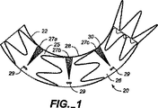
図1および図2Aおよび図2Bを参照すると、実施形態の補綴具20が示されており、この補綴具20では、移植片は、補綴具が移植片材の拡張可能な部分で展開される身体の内腔の生体構造に補綴具を一致させるように構成されている。補綴具20は、管状移植片25と、この管状移植片25に取付けられた半径方向に圧縮可能な環状支持部材22とを備えている。環状支持部材22は、移植片を支持し、および/または補綴具20を付勢して大動脈100(図3および図4参照)の内面と一致的に固定係合させる。環状支持部材22は、所定の半径を有するばね部材であり、そして超弾性の形状設定状態でニチノールのような材料で構成されている。
Embodiments of the present invention will be described in detail below with reference to the accompanying drawings.
Referring to FIGS. 1 and 2A and 2B, an
管状移植片25は、主管状部分26と、移植片25の長さに沿って半円筒形部分28に位置決めされた一連の拡張可能な移植片部分27aないし27cとを備えている(ここで定められるように、半円筒形部分は湾曲されるべき管の円形周囲の2分の1に限定されない。何故なら、ステント移植片が設置されるべき曲線の外側における移植片材は(全く)伸びず、可撓性材料の一部が、周囲のまわりの少なくとも中途までだが、おそらく、周囲のまわりの2/ないし3/4ないし7/までに達する必要があり、その構成のすべてが、半分またはそれ以上だが、周囲全体未満、または周囲全体の90%未満である半円筒形部分と称せられるかも知れないからである)。拡張可能な部分27aないし27cは、図2Bに示されるように、管状補綴具20の半円筒形部分28のまわりに巻きついているか、或は半円筒形部分28のまわりに形成されている。
管状移植片の拡張可能な部分27aないし27cは環状支持部材により比較的支持されておらず(すなわち、支持部材により直接に支持されておらず、例えば、拡張可能な部分の移植片材に取付けられておらず)、これらの部分は比較的可撓性である(すなわち、管状移植片の主管状部分26より可撓性である)。主管状部分26は織製ポリエステルまたはダクロンのような第1の生物適合性の低多孔性織布で形成されている。タレント(登録商標)ステント移植片が使用される場合、主要ステント移植片材は、薄い織製物フィラメントであり、このフィラメントは、比較的剛性であると考えられ、そしてこの材料の環状移植片が弧状形状に形成されると、流れ内腔の面積を減少させる刻み目またはねじれを生じる。フィラメント材料の説明はグリーン等の米国特許第6,344,052号(これは出典を明示することにより本願明細書の開示の一部とされる)に見られることができる。一連の拡張可能な部分27は、周方向パターンで配向され、環状移植片25の主部分26に縫い付けられる波状折り部30を有する軟質の波状織製ダクロン(例えば、クーレイ(登録商標)、ベニソフト(登録商標)材料)で形成されている。波状折り部30は材料をマンドレルに設置し、ワイヤを材料の管のまわりに巻きつけることによって形成されてもよい。(例えば、材料の管をマンドレルのまわりに設置して折り部を形成してもよく、次いで一部を切断して拡張部分を生じてもよい。)かくして、波状材料は拡張したり収縮したりするアコーディオンのように作用する。移植片材は、補綴具が小さい直径に圧縮され得るが、それでも円筒形管状形態へ拡張すると、強い耐漏れ性の流体導管として作用することが可能であるように、薄肉である。
The expandable portion 27a-27c of the tubular graft is relatively unsupported by the annular support member (ie, not directly supported by the support member, eg attached to the expandable portion of the graft material). These portions are relatively flexible (ie, more flexible than the main
拡張可能な部分27aないし27cは、拡張されると(図2A)、(図2Aに示されるように側部から見て)より大きい三角形または楔形状の輪郭を有する。逆に、拡張可能な部分27aないし27cは、圧縮されると、折り部を閉じ、(図1に示されるように側部から見て)より小さい三角形または楔形状の輪郭を有する。図2Aに示されるように拡張されると、拡張可能な部分27aないし27cは拡張して管状移植片25の半円形の側部分28を支持する。拡張可能な部分27aないし27cの可撓性/折り曲げ性により、補綴具20は壁部の圧縮をこれらの領域に集中させ、そしてタレント(登録商標)ステント移植片のような一様な移植片材壁部構成のステント移植片と比較して、ステント移植片をねじれが減少された状態で折り曲げるか或は湾曲させることができる。拡張可能な部分27aないし27cを圧縮すると、折り部を閉じ、管状移植片25の半円筒形部分28に沿って補綴具の長さを減少させることにより曲線を生じる。
この実施形態では、環状支持部材22は縫合糸により管状移植片25の外側に縫い付けされている。(材料内への埋め込みまたは巻きつけ、接着剤、ステープルまたは他の機械的コネクタのような)別の取付け機構を使用してもよく、環状支持部材22を管状移植片25の内側に取付けてもよい。支持部材22は一連の起伏のあるリング部材よりなる。
The expandable portions 27a-27c, when expanded (FIG. 2A), have a larger triangular or wedge-shaped profile (as viewed from the side as shown in FIG. 2A). Conversely, the expandable portions 27a-27c, when compressed, close the fold and have a smaller triangular or wedge-shaped profile (as viewed from the side as shown in FIG. 1). When expanded as shown in FIG. 2A, the expandable portions 27 a-27 c expand to support the
In this embodiment, the
図3および図4には、血管壁部が弱まって拡張されている疾患領域105を除く或は迂回する胸部大動脈における適所にある補綴具が示されている。補綴儀20は、弱まった疾患領域105または動脈瘤を通る流体導管として作用することにより弱まった血管壁部に対する血液の圧力を除去するために使用される。補綴具20は、その展開構成において、大動脈100を通る血液の流れのための導管を構成する。展開時、環状支持部材22は、疾患領域105の上流および下流で大動脈100の内面との一致的な固定係合状態へ内腔内補綴具20の管状移植片25を付勢するのに十分な半径方向外方の力を及ぼすように設計されている。展開時、拡張可能な部分27aないし27cは、移植片材が血管の形状に一致し、それにより血管が湾曲する場合のねじれを減少させるのに必要であるように、管状移植片25を折り曲げたり撓ませたりすることができる。
図3および図4に示されるように、拡張可能な部分27aないし27cを圧縮して、部分27cが伸張されている、すなわち、開放されている間、移植片25を大動脈100の半径のより小さい湾曲部分107のところで湾曲させる。環状部材22は、管状移植片25を支持するように、および/または補綴具20と大動脈100の内壁部との間に耐漏れ性のシールを行うようにも作用する。
FIGS. 3 and 4 show the prosthesis in place in the thoracic aorta that excludes or bypasses the
As shown in FIGS. 3 and 4, the expandable portions 27a-27c are compressed so that the portion 25c is expanded, i.e., the
補綴具20を展開するために、拡張可能な部分27aないし27cが伸張され、且つ環状支持部材22が半径方向に圧縮された構成に保持されているまっすぐな姿勢で補綴具20をカテーテル(図示せず)に装填する。薄い可撓性のシースまたはカバー(図示せず)を補綴具20に設置して補綴具を拘束し、且つ補綴具が動脈瘤部位に送出されるときに補綴具が内腔壁部を損傷したり、そこに引っ掛かったりするのを防ぐ。補綴具20を半径方向に圧縮された状態でカテーテルを経て外科的に接近された血管系を通して所望の展開部位まで送出す。カテーテルの遠位端部が展開部位に位置決めされると、当業者により良く理解されるような方法でカバーを後退させる。環状移植片25は、更に、展開前、半円筒形部分28が血管の半径のより小さい湾曲部分107と整合されるように、補綴具20を造影下で配向することができるように、拡張可能な部分27aないし27cおよび半円筒形部分28に対して所定の位置で移植片材に縫い付けられる放射線不透過性マーカー29を有している。環状支持部材22は拡張して補綴具を付勢して動脈瘤部位または疾患部位105の上流および下流で血管の内面と一致的な固定係合させ且つ血管壁部に係合させる。拡張可能な部分27aないし27cは血管の生体構造に可撓性的に拡張するか或は収縮する。拡張および収縮は、例えば、波状部分を折り曲げたり広げたりすることによってもよいし、或は材料を伸張したり緩めたりすることによってもよい。
To deploy the
外科手術部位に接近するための外科方法および装置が当業界で一般に知られており、このような方法および装置はカテーテルを血管系内に設置し、補綴具を展開部位まで送出すために使用されてもよい。更に、シースを後退させるための種々の作動機構、および望むなら、バルーンカテーテルのバルーンの膨らましは当業界で知られている。補綴具は幾つかの方法のうちの1つにより展開部位まで送出されてもよい。大腿部動脈に接近するために、外科的切開を行ってもよい。その場合、蛍光透視造影を使用してカテーテルを動脈に挿入し、そして動脈瘤部位まで案内し、次いで、そこで装置を展開する。移植片を支持していて、半径方向外方に付勢されている環状支持部材を解放して血管内の補綴具を拡張して血管壁部に係合させ、それにより血液の流れのための人造内腔を生じる。他の技術としては、カテーテルの送出しのための、すなわち、外科的切開なしの血管への経皮的な接近が挙げられる。このような技術の例は米国特許第5,713,917号(これは出典を明示することにより本願明細書の開示の一部とされる)に記載されている。 Surgical methods and devices for accessing a surgical site are generally known in the art, and such methods and devices are used to place a catheter within the vasculature and deliver a prosthesis to a deployment site. May be. In addition, various actuation mechanisms for retracting the sheath and, if desired, balloon inflation of the balloon catheter are known in the art. The prosthetic device may be delivered to the deployment site by one of several methods. A surgical incision may be made to access the femoral artery. In that case, fluoroscopy is used to insert the catheter into the artery and guide it to the aneurysm site, whereupon the device is deployed. The annular support member supporting the graft and biased radially outward is released to expand the prosthesis in the vessel and engage the vessel wall, thereby allowing blood flow Creates an artificial lumen. Other techniques include percutaneous access to the vessel for delivery of the catheter, i.e., without a surgical incision. An example of such a technique is described in US Pat. No. 5,713,917, which is incorporated herein by reference.
この実施形態では、移植片はその長さの一方の側に沿って湾曲している。しかしながら、移植片は、対応する部分の血管の湾曲に合致する移植片の側部の長さの一部に拡張可能な部分を設けることによって、色々な湾曲の他の血管にぴったり合い、且つ捩れるように設計されることができる。更に、拡張可能な部分は、それらの拡張範囲が拡張時に移植片の長さのより大きい弧状側のための湾曲部分を設けるように、すなわち、これらの部分が、収縮時、1つの配向または方向における湾曲部を設け、実質的に拡張されたときに、反対の配向における湾曲部を設けるように(すなわち、拡張可能な部分を湾曲された血管のより大きい弧状部分に位置決めするように)、構成されてもよい。また、この装置は、特定の患者の血管の湾曲にぴったり合うように注文製造されることもでき、また、例えば、色々な角度で開き、および/または移植片の周囲のまわりにその長さに沿って色々な位置に位置決めされる折り部を生じることもできる。
本発明を特定の実施形態について説明したが、当業者には、本発明の精神および範囲を逸脱することになしに形態および詳細の多くの変形例および変更例を行なうことができることは理解されるであろう。
In this embodiment, the implant is curved along one side of its length. However, the graft fits into other vessels of various curvatures and is twisted by providing an expandable portion on a portion of the side length of the graft that matches the curvature of the corresponding portion of the vessel. Can be designed to be. Further, the expandable portions provide a curved portion for the arcuate side of the graft whose expansion range is greater when expanded, i.e., when these portions are contracted, they are in one orientation or direction. Configured to provide a bend in the opposite orientation when substantially expanded (ie, to position the expandable portion on a larger arcuate portion of the curved vessel) when substantially expanded May be. The device can also be custom-made to fit the curvature of a particular patient's blood vessel, eg, open at various angles and / or to its length around the periphery of the implant. Folds can also be produced that are positioned at various positions along.
Although the invention has been described with reference to specific embodiments, those skilled in the art will recognize that many variations and modifications in form and detail may be made without departing from the spirit and scope of the invention. Will.
Claims (12)
前記身体流体の流れが通る内腔を形成する移植片材を備えている管状移植片と、
前記移植片材に連結され該移植片材を支持する少なくとも1つの環状支持部材と、を備え、
前記移植片材は、第1移植片材と、該第1移植片材に取付けられた第2移植片材の少なくとも1つの部分とを備え、
前記第2移植片材は、前記第1移植片材とは異なった材料であり、
前記補綴具は、該補綴具の湾曲部分を構成するために湾曲するように構成された部分を備え、
前記第2移植片材の少なくとも1つの部分は前記部分に配置され、前記第2移植片材は、身体流体の流れのための内腔を妨げることなしに前記より小さい湾曲部分を形成するために湾曲するように構成されている、
ことを特徴とする内腔内補綴具。An endoluminal prosthesis for providing a lumen through which a body fluid flow passes ,
A tubular graft and a graft material forming a lumen through which flow of said body fluid,
At least one of the annular support member for supporting the coupled graft material, wherein the graft material, Bei give a,
The implant material includes a first graft material, Bei example and at least one portion of the second graft material attached to the first implant member,
The second graft material is a material different from the first graft material,
The prosthesis example Bei a portion configured to bend in order to configure the curved portion of the prosthesis,
At least one portion of the second graft material is disposed on the portion so that the second graft material forms the smaller curved portion without interfering with a lumen for body fluid flow. Configured to bend,
An endoluminal prosthesis characterized by the above.
請求項1に記載の内腔内補綴具。The second graft material is a wave profile,
The endoluminal prosthesis according to claim 1.
請求項1に記載の内腔内補綴具。Said tubular graft example Bei the unsupported portion, the non-support portion comprises a portion of said at least one portion,
The endoluminal prosthesis according to claim 1.
請求項1に記載の内腔内補綴具。Wherein at least one portion comprises a plurality of portions,
The endoluminal prosthesis according to claim 1.
請求項1に記載の内腔内補綴具。At least one portion of the second graft material comprises a plurality of portions disposed in the portion ;
The endoluminal prosthesis according to claim 1.
請求項1に記載の内腔内補綴具。 When the prosthesis is deployed, in order to confirm the angular position of the prosthesis using the imaging device, wherein at a predetermined position with respect to at least one portion, further comprising a marker attached to the prosthesis ing,
The endoluminal prosthesis according to claim 1.
内腔を形成する管状移植片手段を備え、
該管状移植片手段は、前記補綴具手段を、前記内腔を妨げないようにしながら、該補綴具手段が展開される身体内腔の生体構造に一致するように湾曲させる移植片材手段を備え、
前記移植片材手段は、前記補綴具手段の一部の長さを変化させる手段を備え、
前記移植片材手段は、前記内腔を設ける主構成要素手段と、前記管状移植片手段を湾曲可能とする第2構成要素手段とを備え、
前記第2構成要素手段が、前記長さを変化させる手段を備え、
前記主構成要素手段は、前記第2構成要素手段に含まれる材料と異なった材料を備えている、
ことを特徴とする内腔内補綴具手段。An endoluminal prosthetic means for providing a lumen through which a flow of bodily fluid passes , comprising:
Comprising tubular graft means for forming a lumen ;
Tubular implant means, said prosthesis means, while not interfere with the lumen, the graft material means for bending such that the prosthesis means matches the anatomy of the body lumen to be deployed Prepared,
The graft material means comprises means for changing the length of a portion of the prosthetic means,
The graft material means comprises main component means for providing the lumen, and second component means for allowing the tubular graft means to bend,
The second component means comprises means for changing the length;
The main component means comprises a material different from that contained in the second component means,
An endoluminal prosthesis means characterized by the above .
請求項7に記載の内腔内補綴具手段。The endoluminal prosthesis means according to claim 7.
請求項7に記載の内腔内補綴具手段。Means for altering the length comprises a means for varying the length for bending the prosthesis device,
The endoluminal prosthesis means according to claim 7.
請求項9に記載の内腔内補綴具手段。It means for varying the length comprises means for causing changing the length to straighten the prosthesis means,
The endoluminal prosthesis means according to claim 9.
請求項7に記載の内腔内補綴具手段。 The second component means comprises segmenting means that curves at a position where a desired smaller bending means should be provided to accommodate the curvature of the blood vessel.
The endoluminal prosthesis means according to claim 7.
請求項7に記載の内腔内補綴具手段。Further comprising a marker means for providing information about the position of the prosthesis device,
The endoluminal prosthesis means according to claim 7.
Applications Claiming Priority (3)
| Application Number | Priority Date | Filing Date | Title |
|---|---|---|---|
| US58926004P | 2004-07-20 | 2004-07-20 | |
| US60/589,260 | 2004-07-20 | ||
| PCT/US2005/025423 WO2006020222A1 (en) | 2004-07-20 | 2005-07-19 | Endoluminal prosthesis having expandable graft sections |
Publications (3)
| Publication Number | Publication Date |
|---|---|
| JP2008507340A JP2008507340A (en) | 2008-03-13 |
| JP2008507340A5 JP2008507340A5 (en) | 2008-09-04 |
| JP4901733B2 true JP4901733B2 (en) | 2012-03-21 |
Family
ID=35079304
Family Applications (1)
| Application Number | Title | Priority Date | Filing Date |
|---|---|---|---|
| JP2007522621A Expired - Fee Related JP4901733B2 (en) | 2004-07-20 | 2005-07-19 | Intraluminal prosthesis with an expandable graft portion |
Country Status (4)
| Country | Link |
|---|---|
| US (1) | US7318835B2 (en) |
| EP (1) | EP1778132B1 (en) |
| JP (1) | JP4901733B2 (en) |
| WO (2) | WO2006020222A1 (en) |
Families Citing this family (54)
| Publication number | Priority date | Publication date | Assignee | Title |
|---|---|---|---|---|
| US7318835B2 (en) | 2004-07-20 | 2008-01-15 | Medtronic Vascular, Inc. | Endoluminal prosthesis having expandable graft sections |
| US8287583B2 (en) * | 2005-01-10 | 2012-10-16 | Taheri Laduca Llc | Apparatus and method for deploying an implantable device within the body |
| WO2006113501A1 (en) * | 2005-04-13 | 2006-10-26 | The Cleveland Clinic Foundation | Endoluminal prosthesis |
| CN2817768Y (en) * | 2005-05-24 | 2006-09-20 | 微创医疗器械(上海)有限公司 | Tectorium stand and host cage section thereof |
| WO2007098937A1 (en) * | 2006-02-28 | 2007-09-07 | Angiomed Gmbh & Co. Medizintechnik Kg | Flexible stretch stent-graft |
| ATE544428T1 (en) * | 2006-09-28 | 2012-02-15 | Cook Medical Technologies Llc | DEVICE FOR REPAIRING AORTIC ANEURYSMS IN THE CHEST |
| ATE461675T1 (en) * | 2006-10-24 | 2010-04-15 | Cook Inc | STENT ELEMENT |
| BRPI0807260A2 (en) | 2007-02-09 | 2014-06-10 | Taheri Laduca Llc | "IMPLANTABLE STENT AND METHOD OF MANUFACTURING A TUBULAR GRAFT" |
| US8663309B2 (en) * | 2007-09-26 | 2014-03-04 | Trivascular, Inc. | Asymmetric stent apparatus and method |
| US20090082841A1 (en) * | 2007-09-26 | 2009-03-26 | Boston Scientific Corporation | Apparatus for securing stent barbs |
| CN101917929A (en) * | 2007-10-04 | 2010-12-15 | 特里瓦斯库拉尔公司 | Modular vascular graft for low profile percutaneous delivery |
| WO2009086200A1 (en) * | 2007-12-20 | 2009-07-09 | Trivascular2, Inc. | Hinged endovascular device |
| US9226813B2 (en) | 2007-12-26 | 2016-01-05 | Cook Medical Technologies Llc | Low profile non-symmetrical stent |
| GB2475494B (en) | 2009-11-18 | 2011-11-23 | Cook William Europ | Stent graft and introducer assembly |
| US8574284B2 (en) | 2007-12-26 | 2013-11-05 | Cook Medical Technologies Llc | Low profile non-symmetrical bare alignment stents with graft |
| GB2476451A (en) * | 2009-11-19 | 2011-06-29 | Cook William Europ | Stent Graft |
| US9180030B2 (en) | 2007-12-26 | 2015-11-10 | Cook Medical Technologies Llc | Low profile non-symmetrical stent |
| FR2926214B1 (en) * | 2008-01-10 | 2010-12-31 | Novatech Sa | ENDOPROSTHESIS FOR ANATOMICAL CANAL |
| US20090287145A1 (en) * | 2008-05-15 | 2009-11-19 | Altura Interventional, Inc. | Devices and methods for treatment of abdominal aortic aneurysms |
| WO2009145913A1 (en) * | 2008-05-30 | 2009-12-03 | Med Institute, Inc. | Kink-resistant stent graft |
| US9539120B2 (en) * | 2008-10-10 | 2017-01-10 | Veryan Medical Ltd. | Medical device suitable for location in a body lumen |
| EP2349127B1 (en) | 2008-10-10 | 2016-01-13 | Veryan Medical Limited | A medical device suitable for location in a body lumen |
| GB2464978B (en) * | 2008-10-31 | 2010-10-20 | Cook William Europ | Introducer for deploying a stent graft in a curved lumen |
| JP5855460B2 (en) | 2008-11-24 | 2016-02-09 | ヴァスキュラー グラフト ソリューションズ リミテッド | External stent |
| US20100174357A1 (en) * | 2009-01-07 | 2010-07-08 | Lemaitre Vascular, Inc. | Vascular Prosthesis of Varying Flexibility |
| US8641753B2 (en) | 2009-01-31 | 2014-02-04 | Cook Medical Technologies Llc | Preform for and an endoluminal prosthesis |
| US10456276B2 (en) | 2009-05-08 | 2019-10-29 | Veryan Medical Limited | Medical device suitable for location in a body lumen |
| US8858613B2 (en) | 2010-09-20 | 2014-10-14 | Altura Medical, Inc. | Stent graft delivery systems and associated methods |
| US8403988B2 (en) | 2009-09-11 | 2013-03-26 | Depuy Spine, Inc. | Minimally invasive intervertebral staple distraction devices |
| US9615933B2 (en) * | 2009-09-15 | 2017-04-11 | DePuy Synthes Products, Inc. | Expandable ring intervertebral fusion device |
| US9757263B2 (en) | 2009-11-18 | 2017-09-12 | Cook Medical Technologies Llc | Stent graft and introducer assembly |
| US20110130825A1 (en) * | 2009-12-01 | 2011-06-02 | Altura Medical, Inc. | Modular endograft devices and associated systems and methods |
| US10292809B2 (en) | 2009-12-28 | 2019-05-21 | Cook Medical Technologies Llc | Thoracic graft having yarn modifications |
| US9925031B2 (en) | 2009-12-28 | 2018-03-27 | Cook Medical Technologies Llc | Endoluminal device with kink-resistant regions |
| WO2011100367A2 (en) * | 2010-02-10 | 2011-08-18 | Trivascular, Inc. | Fill tube manifold and delivery methods for endovascular graft |
| US8920486B2 (en) | 2010-05-18 | 2014-12-30 | RBKPark, LLC | Medical device |
| US9095466B2 (en) | 2010-11-16 | 2015-08-04 | W. L. Gore & Associates, Inc. | Apposition fiber for use in endoluminal deployment of expandable devices in tortuous anatomies |
| WO2012143925A1 (en) | 2011-04-18 | 2012-10-26 | Vascular Graft Solutions Ltd | Devices and methods for deploying implantable sleeves over blood vessels |
| AU2012203620B9 (en) | 2011-06-24 | 2014-10-02 | Cook Medical Technologies Llc | Helical Stent |
| GB2494632A (en) * | 2011-09-09 | 2013-03-20 | Isis Innovation | Stent and method of inserting a stent into a delivery catheter |
| US8992595B2 (en) | 2012-04-04 | 2015-03-31 | Trivascular, Inc. | Durable stent graft with tapered struts and stable delivery methods and devices |
| US9498363B2 (en) | 2012-04-06 | 2016-11-22 | Trivascular, Inc. | Delivery catheter for endovascular device |
| CN105050549B (en) | 2012-08-10 | 2017-07-21 | 阿尔图拉医疗公司 | Stent delivery system and associated method |
| WO2014144809A1 (en) | 2013-03-15 | 2014-09-18 | Altura Medical, Inc. | Endograft device delivery systems and associated methods |
| WO2016149605A2 (en) * | 2015-03-19 | 2016-09-22 | The Secant Group, Llc | Textile engineered prosthetics, bioreactors, and methods of manufacturing textile engineered prosthetics |
| JP2018525108A (en) * | 2015-08-31 | 2018-09-06 | サンフォード ヘルス | Precurved stent graft and method of use |
| CA3031569C (en) * | 2016-08-08 | 2021-03-16 | W. L. Gore & Associates, Inc. | Kink resistant graft |
| CN111093533B (en) * | 2017-07-14 | 2024-03-08 | 恩朵罗杰克斯有限责任公司 | Stent graft and method for enhancing flexibility of stent graft by heat pleating |
| CN107397610A (en) * | 2017-08-25 | 2017-11-28 | 杭州唯强医疗科技有限公司 | Overlay film frame |
| WO2019128703A1 (en) * | 2017-12-27 | 2019-07-04 | 先健科技(深圳)有限公司 | Covered stent |
| KR102025817B1 (en) * | 2018-02-20 | 2019-09-26 | 중앙대학교 산학협력단 | Artificial blood vessel and package for the same |
| AU2020242051A1 (en) | 2019-03-20 | 2021-11-04 | inQB8 Medical Technologies, LLC | Aortic dissection implant |
| CN115003252A (en) * | 2020-07-07 | 2022-09-02 | 国立大学法人广岛大学 | Stent graft |
| KR102528141B1 (en) * | 2020-11-13 | 2023-05-09 | 주식회사 시브이바이오 | Graft stent with different skin lengths for each location in preparation for the curve of blood vessels |
Family Cites Families (12)
| Publication number | Priority date | Publication date | Assignee | Title |
|---|---|---|---|---|
| US6193745B1 (en) * | 1995-10-03 | 2001-02-27 | Medtronic, Inc. | Modular intraluminal prosteheses construction and methods |
| US5824037A (en) * | 1995-10-03 | 1998-10-20 | Medtronic, Inc. | Modular intraluminal prostheses construction and methods |
| US5591195A (en) * | 1995-10-30 | 1997-01-07 | Taheri; Syde | Apparatus and method for engrafting a blood vessel |
| US5824042A (en) * | 1996-04-05 | 1998-10-20 | Medtronic, Inc. | Endoluminal prostheses having position indicating markers |
| US6344052B1 (en) * | 1999-09-27 | 2002-02-05 | World Medical Manufacturing Corporation | Tubular graft with monofilament fibers |
| ES2223759T3 (en) * | 2001-03-27 | 2005-03-01 | William Cook Europe Aps | AORTIC GRAFT DEVICE. |
| AUPR847301A0 (en) * | 2001-10-26 | 2001-11-15 | Cook Incorporated | Endoluminal prostheses for curved lumens |
| WO2003051232A1 (en) | 2001-12-14 | 2003-06-26 | Aesculap Ag & Co. Kg | Vessel prosthesis, particularly for the replacement of aorta segments near the heart |
| US20040019375A1 (en) * | 2002-07-26 | 2004-01-29 | Scimed Life Systems, Inc. | Sectional crimped graft |
| US7189255B2 (en) * | 2003-10-28 | 2007-03-13 | Cordis Corporation | Prosthesis support ring assembly |
| JP2005324108A (en) * | 2004-05-13 | 2005-11-24 | Honda Motor Co Ltd | Resin covering method for capillary inner wall |
| US7318835B2 (en) | 2004-07-20 | 2008-01-15 | Medtronic Vascular, Inc. | Endoluminal prosthesis having expandable graft sections |
-
2005
- 2005-07-13 US US11/181,384 patent/US7318835B2/en active Active
- 2005-07-19 EP EP05773780.1A patent/EP1778132B1/en not_active Not-in-force
- 2005-07-19 JP JP2007522621A patent/JP4901733B2/en not_active Expired - Fee Related
- 2005-07-19 WO PCT/US2005/025423 patent/WO2006020222A1/en active Application Filing
-
2006
- 2006-06-28 WO PCT/US2006/024920 patent/WO2007008398A1/en active Application Filing
Also Published As
| Publication number | Publication date |
|---|---|
| US20060030926A1 (en) | 2006-02-09 |
| EP1778132B1 (en) | 2017-11-15 |
| EP1778132A1 (en) | 2007-05-02 |
| JP2008507340A (en) | 2008-03-13 |
| WO2006020222A1 (en) | 2006-02-23 |
| US7318835B2 (en) | 2008-01-15 |
| WO2007008398A1 (en) | 2007-01-18 |
Similar Documents
| Publication | Publication Date | Title |
|---|---|---|
| JP4901733B2 (en) | Intraluminal prosthesis with an expandable graft portion | |
| JP6353593B2 (en) | Endoluminal prosthesis with a bifurcated section that can be turned | |
| JP5691006B2 (en) | Flexible stent graft | |
| US10603196B2 (en) | Fenestrated prosthesis | |
| JP6100995B2 (en) | Shape-adapted prosthesis supply system and arrangement method thereof | |
| AU2008323540B2 (en) | Hybrid intraluminal device | |
| US8128686B2 (en) | Branched vessel prosthesis | |
| US8905961B2 (en) | Systems, apparatuses, and methods for cardiovascular conduits and connectors | |
| JP2005506874A (en) | Curved lumen prosthesis | |
| JP2004344489A (en) | Temporary indwelling stent and stent graft | |
| WO2007028112A2 (en) | Methods and apparatus for treatment of aneurysms adjacent to branch arteries | |
| CN112702980A (en) | Low profile delivery system with locking wire lumen | |
| JP2022539978A (en) | stent graft prosthesis | |
| AU2002348080A1 (en) | Prostheses for curved lumens |
Legal Events
| Date | Code | Title | Description |
|---|---|---|---|
| A521 | Request for written amendment filed |
Free format text: JAPANESE INTERMEDIATE CODE: A523 Effective date: 20080717 |
|
| A621 | Written request for application examination |
Free format text: JAPANESE INTERMEDIATE CODE: A621 Effective date: 20080717 |
|
| A131 | Notification of reasons for refusal |
Free format text: JAPANESE INTERMEDIATE CODE: A131 Effective date: 20101206 |
|
| A601 | Written request for extension of time |
Free format text: JAPANESE INTERMEDIATE CODE: A601 Effective date: 20110307 |
|
| A602 | Written permission of extension of time |
Free format text: JAPANESE INTERMEDIATE CODE: A602 Effective date: 20110314 |
|
| A521 | Request for written amendment filed |
Free format text: JAPANESE INTERMEDIATE CODE: A523 Effective date: 20110606 |
|
| TRDD | Decision of grant or rejection written | ||
| A01 | Written decision to grant a patent or to grant a registration (utility model) |
Free format text: JAPANESE INTERMEDIATE CODE: A01 Effective date: 20111219 |
|
| A01 | Written decision to grant a patent or to grant a registration (utility model) |
Free format text: JAPANESE INTERMEDIATE CODE: A01 |
|
| A61 | First payment of annual fees (during grant procedure) |
Free format text: JAPANESE INTERMEDIATE CODE: A61 Effective date: 20111227 |
|
| R150 | Certificate of patent or registration of utility model |
Ref document number: 4901733 Country of ref document: JP Free format text: JAPANESE INTERMEDIATE CODE: R150 Free format text: JAPANESE INTERMEDIATE CODE: R150 |
|
| FPAY | Renewal fee payment (event date is renewal date of database) |
Free format text: PAYMENT UNTIL: 20150113 Year of fee payment: 3 |
|
| R250 | Receipt of annual fees |
Free format text: JAPANESE INTERMEDIATE CODE: R250 |
|
| R250 | Receipt of annual fees |
Free format text: JAPANESE INTERMEDIATE CODE: R250 |
|
| R250 | Receipt of annual fees |
Free format text: JAPANESE INTERMEDIATE CODE: R250 |
|
| R250 | Receipt of annual fees |
Free format text: JAPANESE INTERMEDIATE CODE: R250 |
|
| R250 | Receipt of annual fees |
Free format text: JAPANESE INTERMEDIATE CODE: R250 |
|
| R250 | Receipt of annual fees |
Free format text: JAPANESE INTERMEDIATE CODE: R250 |
|
| R250 | Receipt of annual fees |
Free format text: JAPANESE INTERMEDIATE CODE: R250 |
|
| R250 | Receipt of annual fees |
Free format text: JAPANESE INTERMEDIATE CODE: R250 |
|
| LAPS | Cancellation because of no payment of annual fees |