JP4900773B2 - Float glass manufacturing apparatus and method - Google Patents
Float glass manufacturing apparatus and method Download PDFInfo
- Publication number
- JP4900773B2 JP4900773B2 JP2005340131A JP2005340131A JP4900773B2 JP 4900773 B2 JP4900773 B2 JP 4900773B2 JP 2005340131 A JP2005340131 A JP 2005340131A JP 2005340131 A JP2005340131 A JP 2005340131A JP 4900773 B2 JP4900773 B2 JP 4900773B2
- Authority
- JP
- Japan
- Prior art keywords
- casing
- linear motor
- float glass
- magnetic field
- bottom casing
- Prior art date
- Legal status (The legal status is an assumption and is not a legal conclusion. Google has not performed a legal analysis and makes no representation as to the accuracy of the status listed.)
- Expired - Fee Related
Links
- 238000004519 manufacturing process Methods 0.000 title claims description 41
- 239000005329 float glass Substances 0.000 title claims description 27
- 238000000034 method Methods 0.000 title description 5
- 239000002184 metal Substances 0.000 claims description 45
- 229910052751 metal Inorganic materials 0.000 claims description 45
- 239000011449 brick Substances 0.000 claims description 35
- 238000001816 cooling Methods 0.000 claims description 27
- XLYOFNOQVPJJNP-UHFFFAOYSA-N water Substances O XLYOFNOQVPJJNP-UHFFFAOYSA-N 0.000 claims description 10
- 239000011810 insulating material Substances 0.000 claims description 7
- 239000000696 magnetic material Substances 0.000 claims description 6
- 229910001220 stainless steel Inorganic materials 0.000 claims description 3
- 239000010935 stainless steel Substances 0.000 claims description 3
- ATJFFYVFTNAWJD-UHFFFAOYSA-N Tin Chemical compound [Sn] ATJFFYVFTNAWJD-UHFFFAOYSA-N 0.000 description 35
- 239000006060 molten glass Substances 0.000 description 21
- 239000005357 flat glass Substances 0.000 description 20
- 239000011521 glass Substances 0.000 description 11
- 230000020169 heat generation Effects 0.000 description 8
- 230000003628 erosive effect Effects 0.000 description 7
- 238000002844 melting Methods 0.000 description 7
- 230000008018 melting Effects 0.000 description 7
- 238000010583 slow cooling Methods 0.000 description 5
- 238000006124 Pilkington process Methods 0.000 description 4
- VYPSYNLAJGMNEJ-UHFFFAOYSA-N Silicium dioxide Chemical compound O=[Si]=O VYPSYNLAJGMNEJ-UHFFFAOYSA-N 0.000 description 4
- 239000000463 material Substances 0.000 description 3
- 239000004745 nonwoven fabric Substances 0.000 description 3
- OKTJSMMVPCPJKN-UHFFFAOYSA-N Carbon Chemical compound [C] OKTJSMMVPCPJKN-UHFFFAOYSA-N 0.000 description 2
- 229910000963 austenitic stainless steel Inorganic materials 0.000 description 2
- 229910052799 carbon Inorganic materials 0.000 description 2
- 239000000498 cooling water Substances 0.000 description 2
- 230000006698 induction Effects 0.000 description 2
- 239000004973 liquid crystal related substance Substances 0.000 description 2
- XEEYBQQBJWHFJM-UHFFFAOYSA-N Iron Chemical group [Fe] XEEYBQQBJWHFJM-UHFFFAOYSA-N 0.000 description 1
- PNEYBMLMFCGWSK-UHFFFAOYSA-N aluminium oxide Inorganic materials [O-2].[O-2].[O-2].[Al+3].[Al+3] PNEYBMLMFCGWSK-UHFFFAOYSA-N 0.000 description 1
- 230000015572 biosynthetic process Effects 0.000 description 1
- 238000007664 blowing Methods 0.000 description 1
- 239000004927 clay Substances 0.000 description 1
- 230000007423 decrease Effects 0.000 description 1
- 230000000694 effects Effects 0.000 description 1
- 239000004744 fabric Substances 0.000 description 1
- 239000012530 fluid Substances 0.000 description 1
- 230000004907 flux Effects 0.000 description 1
- 239000003365 glass fiber Substances 0.000 description 1
- 230000005484 gravity Effects 0.000 description 1
- 230000009257 reactivity Effects 0.000 description 1
- 230000000630 rising effect Effects 0.000 description 1
- 239000000377 silicon dioxide Substances 0.000 description 1
- 229910052851 sillimanite Inorganic materials 0.000 description 1
- 239000005361 soda-lime glass Substances 0.000 description 1
Images


Classifications
-
- C—CHEMISTRY; METALLURGY
- C03—GLASS; MINERAL OR SLAG WOOL
- C03B—MANUFACTURE, SHAPING, OR SUPPLEMENTARY PROCESSES
- C03B18/00—Shaping glass in contact with the surface of a liquid
- C03B18/02—Forming sheets
- C03B18/16—Construction of the float tank; Use of material for the float tank; Coating or protection of the tank wall
-
- C—CHEMISTRY; METALLURGY
- C03—GLASS; MINERAL OR SLAG WOOL
- C03B—MANUFACTURE, SHAPING, OR SUPPLEMENTARY PROCESSES
- C03B18/00—Shaping glass in contact with the surface of a liquid
- C03B18/02—Forming sheets
- C03B18/04—Changing or regulating the dimensions of the molten glass ribbon
-
- B—PERFORMING OPERATIONS; TRANSPORTING
- B65—CONVEYING; PACKING; STORING; HANDLING THIN OR FILAMENTARY MATERIAL
- B65G—TRANSPORT OR STORAGE DEVICES, e.g. CONVEYORS FOR LOADING OR TIPPING, SHOP CONVEYOR SYSTEMS OR PNEUMATIC TUBE CONVEYORS
- B65G2201/00—Indexing codes relating to handling devices, e.g. conveyors, characterised by the type of product or load being conveyed or handled
- B65G2201/02—Articles
- B65G2201/0294—Vehicle bodies
Description
本発明は、フロート法によって製造されるフロートガラスの製造装置及びその方法に関する。 The present invention relates to a float glass manufacturing apparatus manufactured by a float process and a method therefor.
フロート法による板ガラスの製造装置は、浴槽に湛えられた溶融錫等の溶融金属上に溶融ガラスを連続供給して溶融金属上を浮遊進行させ、このときに、自己の表面張力と重力に応じた平衡厚さ(約6〜7mm)に達した或いは平衡厚さに達しようとしている、又は平衡厚さ以上の溶融ガラスリボンを、浴槽の出口に隣接した徐冷レアーに向けて引っ張ることにより一定幅の帯状板ガラスを製造する装置である。 The plate glass manufacturing apparatus using the float method continuously supplies molten glass on a molten metal such as molten tin held in a bathtub and floats on the molten metal. At this time, it responds to its own surface tension and gravity. A constant width is achieved by pulling a molten glass ribbon that has reached or is about to reach an equilibrium thickness (approximately 6-7 mm) toward the slow cooling layer adjacent to the bath outlet. It is an apparatus which manufactures the strip | belt-shaped plate glass of this.
ところで、FPD用板ガラスのような、例えば厚み0.1〜1.1mmの液晶用薄板ガラスは、溶融金属上の溶融ガラスリボンを徐冷レヤーに向けて引っ張るだけでは、その厚みを満足することができない。 By the way, for example, a thin glass sheet for liquid crystal having a thickness of 0.1 to 1.1 mm, such as an FPD glass sheet, can satisfy the thickness only by pulling the molten glass ribbon on the molten metal toward the slow cooling layer. Can not.
このため特許文献1に開示された製造装置は、溶融ガラスリボンの両側エッジ部に沿った溶融金属の浴面に凹部を形成し、この凹部に両側エッジ部を流入させて保持しながら、すなわち、溶融ガラスリボンの幅方向に狭まろうとする力を補償しながら所定の薄板ガラスに成形する。この製造装置は、溶融金属の浴面に前記凹部を形成する手段としてリニアモータを備えている。このリニアモータを浴槽の下方に設置し、リニアモータの移動磁界を溶融金属に与え、溶融金属を浴面に対して略鉛直方向に吸引することにより前記凹部を形成している。
ところで、特許文献1に開示されたリニアモータを用いる従来のフロートガラス製造装置は、リニアモータの移動磁界を溶融金属に作用させるが、浴槽の炉床を煉瓦(以下、ボトム煉瓦と称する)で構成し、また、気密性を高めるためにボトム煉瓦の下面を覆うケーシング(以下、ボトムケーシングと称する)を金属によって構成する必要がある。 By the way, the conventional float glass manufacturing apparatus using the linear motor disclosed in Patent Document 1 causes the moving magnetic field of the linear motor to act on the molten metal, but the hearth of the bathtub is composed of bricks (hereinafter referred to as bottom bricks). In addition, in order to improve the airtightness, it is necessary to form a casing (hereinafter referred to as a bottom casing) covering the lower surface of the bottom brick with a metal.
しかしながら、フロートガラス製造装置を上述の如く構成した場合、浴槽内の溶融金属がボトムケーシングから漏出するという虞があった。この漏出原因について説明すると、当該製造装置は、リニアモータの移動磁界をボトムケーシング及びボトム煉瓦を介して溶融金属に与える装置のため、このときに金属製のボトムケーシングに誘導電流が発生し、ボトムケーシングがジュール熱により発熱し昇温する。そして、ボトムケーシングの昇温により、ボトム煉瓦の目地に浸透していた前記溶融金属が加熱されて溶け出し、ボトムケーシングと接触して反応し、ボトムケーシングを浸食する。 However, when the float glass manufacturing apparatus is configured as described above, there is a concern that the molten metal in the bathtub leaks from the bottom casing. The cause of this leakage will be described. Since the manufacturing apparatus is a device that applies the moving magnetic field of the linear motor to the molten metal through the bottom casing and the bottom brick, an induction current is generated in the metal bottom casing at this time, The casing generates heat due to Joule heat and the temperature rises. And by the temperature rise of a bottom casing, the said molten metal which osmose | permeated the joint of the bottom brick is heated and melt | dissolved, it contacts and reacts with a bottom casing, and erodes a bottom casing.
以上の理由により、浴槽内の溶融金属がボトム煉瓦の目地を伝わってボトムケーシングの浸食部から漏出する。例えば、溶融金属として溶融錫を使用した場合、錫の融点は約232℃である。これがボトムケーシングのジュール熱によって更に加熱されると、ボトムケーシングを浸食することとなる。 For the above reasons, the molten metal in the bathtub leaks from the eroded portion of the bottom casing through the joints of the bottom brick. For example, when molten tin is used as the molten metal, the melting point of tin is about 232 ° C. If this is further heated by the Joule heat of the bottom casing, the bottom casing will be eroded.
なお、ボトムケーシングを非磁性体製とすることにより、磁性体製のものと比較して誘導電流を抑えることができるが、前述したジュール熱の発生を大幅に解決するものではない。また、誘導電流を抑えるために、リニアモータに流す電流を小さくした場合には、溶融金属に与える移動磁界が低下するので、溶融金属に与える駆動力が低下し、溶融金属の浴面に好適な凹部を形成することができなくなる問題が生じる。 In addition, by making the bottom casing made of a non-magnetic material, the induced current can be suppressed as compared with that made of a magnetic material, but it does not greatly solve the generation of the Joule heat described above. Also, when the current flowing through the linear motor is reduced in order to suppress the induced current, the moving magnetic field applied to the molten metal is reduced, so that the driving force applied to the molten metal is reduced, which is suitable for the molten metal bath surface. There arises a problem that the recess cannot be formed.
本発明は、このような事情に鑑みてなされたもので、ボトムケーシングの昇温を抑制することにより、ボトムケーシングの浸食を阻止することができるフロートガラスの製造装置及びその方法を提供することを目的とする。 This invention is made | formed in view of such a situation, and provides the manufacturing apparatus and method of the float glass which can prevent erosion of a bottom casing by suppressing the temperature rising of a bottom casing. Objective.
請求項1に記載の発明は、前記目的を達成するために、溶融金属が湛えられた浴槽、浴槽の炉床のボトム煉瓦、ボトム煉瓦の下面にボトム煉瓦を覆うボトムケーシング、ボトムケーシングの下部に溶融金属を磁界により駆動するためのリニアモータが設けられたフロートガラスの製造装置であって、前記ボトムケーシングの少なくともリニアモータの移動磁界の作用するエリアは、非磁性体製のボトムケーシングであり、該ボトムケーシングは冷却構造を有することを特徴とするフロートガラスの製造装置を提供する。 In order to achieve the above-mentioned object, the invention according to claim 1 is a bathtub in which molten metal is provided, a bottom brick of the hearth of the bathtub, a bottom casing that covers the bottom brick on the lower surface of the bottom brick, and a lower portion of the bottom casing. Float glass manufacturing apparatus provided with a linear motor for driving molten metal by a magnetic field, at least the area where the moving magnetic field of the linear motor acts on the bottom casing is a non-magnetic bottom casing, The bottom casing has a cooling structure, and provides a float glass manufacturing apparatus.
請求項1に記載の発明によれば、少なくともリニアモータの移動磁界の作用するエリアの非磁性体製のボトムケーシングに冷却構造を付与し、この冷却構造を利用してボトムケーシングを冷却するので、リニアモータのパワーを落とすことなく、ジュール熱によるボトムケーシングの昇温を抑制できる。これにより、ボトム煉瓦の目地に浸透していた金属の溶融を阻止でき、溶け出した溶融金属との反応によるボトムケーシングの浸食を阻止できる。冷却構造としては、冷却空気をボトムケーシングに直接吹き付けて冷却する空冷によるもの、水冷によるもの等、冷却手段全般を含む。 According to the first aspect of the present invention, the cooling structure is provided to the bottom casing made of a non-magnetic material at least in the area where the moving magnetic field of the linear motor acts, and the bottom casing is cooled using this cooling structure. The temperature rise of the bottom casing due to Joule heat can be suppressed without reducing the power of the linear motor. Thereby, melting of the metal that has penetrated into the joints of the bottom brick can be prevented, and erosion of the bottom casing due to reaction with the molten metal that has melted can be prevented. The cooling structure includes all cooling means such as air cooling that cools air by directly blowing cooling air to the bottom casing, water cooling, and the like.
請求項2に記載の発明は、請求項1において、前記冷却構造は、水冷管構造であることを特徴としている。 The invention described in claim 2 is characterized in that, in claim 1, the cooling structure is a water-cooled tube structure.
冷却構造は、請求項2の如くボトムケーシングに水路を形成した水冷管構造であり、これらの水路に、例えば加圧水循環方式により冷却水を流すことによって実現できる。この冷却構造によれば、ボトムケーシングを直接冷却できるので、高い冷却効率を得ることができる。また、ボトムケーシングの壁面にウォータジャケットを装着することによっても冷却構造を実現できる。 The cooling structure is a water-cooled tube structure in which water passages are formed in the bottom casing as in claim 2 and can be realized by flowing cooling water through these water passages by, for example, a pressurized water circulation system. According to this cooling structure, since the bottom casing can be directly cooled, high cooling efficiency can be obtained. The cooling structure can also be realized by mounting a water jacket on the wall surface of the bottom casing.
請求項3に記載の発明は、前記目的を達成するために、溶融金属が湛えられた浴槽、浴槽の炉床のボトム煉瓦、ボトム煉瓦の下面にボトム煉瓦を覆うボトムケーシング、ボトムケーシングの下部に溶融金属を磁界により駆動するためのリニアモータが設けられたフロートガラスの製造装置であって、前記ボトムケーシングの少なくともリニアモータの移動磁界の作用するエリアが、絶縁材により電気的に相互に絶縁された複数の非磁性体製のケーシング片によって構成されていることを特徴としている。 In order to achieve the above object, a third aspect of the present invention provides a bathtub containing molten metal, a bottom brick of the hearth of the bathtub, a bottom casing that covers the bottom brick on the lower surface of the bottom brick, and a lower portion of the bottom casing. A float glass manufacturing apparatus provided with a linear motor for driving a molten metal by a magnetic field, wherein at least an area of the bottom casing where a moving magnetic field acts is electrically insulated from each other by an insulating material. It is characterized by comprising a plurality of non-magnetic casing pieces.
請求項3に記載の発明によれば、少なくともリニアモータの移動磁界の作用するエリアのボトムケーシングを、例えば錫と親和性のないシリカガラス製不織布等の絶縁材により、電気的に相互に絶縁された複数の非磁性体製のケーシング片によって構成したので、一体構造のケーシング部材によってボトムケーシングを構成したものと比較し、誘導電流を抑制できる。よって、リニアモータのパワーを落とすことなく、ボトムケーシングの昇温を抑制できる。これにより、ボトム煉瓦の目地に浸透していた金属の溶融を阻止でき、溶け出した溶融金属との反応によるボトムケーシングの浸食を阻止できる。また、本発明では、ボトムケーシングの誘導電流によるロスが減少するため、溶融金属への移動磁界が増加し、溶融金属に与える駆動力も向上する。これにより、溶融金属の浴面に、好適な凹部を形成することが可能となる。 According to the invention described in claim 3, at least the bottom casing in the area where the moving magnetic field of the linear motor acts is electrically insulated from each other by an insulating material such as a silica glass non-woven fabric having no affinity for tin. In addition, since the plurality of non-magnetic casing pieces are used, the induced current can be suppressed as compared with the case in which the bottom casing is formed by an integral casing member. Therefore, the temperature rise of the bottom casing can be suppressed without reducing the power of the linear motor. Thereby, melting of the metal that has penetrated into the joints of the bottom brick can be prevented, and erosion of the bottom casing due to reaction with the molten metal that has melted can be prevented. In the present invention, since the loss due to the induced current of the bottom casing is reduced, the moving magnetic field to the molten metal is increased, and the driving force applied to the molten metal is also improved. Thereby, it becomes possible to form a suitable recessed part in the bath surface of a molten metal.
従来装置では、ボトムケーシングに大きな誘導電流が発生していたため、リニアモータに与える電流に制限があったが、本発明のボトムケーシングの誘導電流低減により、リニアモータに与える電流を増加させることができ、溶融金属の駆動力を更に増大させることができる。これにより、溶融金属の浴面に、更に好適な凹部を形成することが可能となる。 In the conventional device, since a large induced current is generated in the bottom casing, there is a limit on the current applied to the linear motor. However, the current applied to the linear motor can be increased by reducing the induced current of the bottom casing of the present invention. The driving force of the molten metal can be further increased. Thereby, it becomes possible to form a more suitable recessed part in the bath surface of a molten metal.
請求項4に記載の発明は、請求項3において、前記ケーシング片は、短冊状であり、その短辺寸法をW(mm)とし、前記リニアモータのポールピッチをτ(mm)とした際に、W≦2τであり、前記リニアモータによる磁界移動方向に対し前記ケーシング片の長辺を略平行に並べて配置されていることを特徴としている。なお、前記リニアモータのポールピッチとは、リニアモータに交流電流を流した際の磁束密度の半波長(半周期の長さ)をいう(産業用リニアモータ(56頁)、著者:山田一、発行所:株式会社工業調査会)。 According to a fourth aspect of the present invention, in the third aspect, the casing piece has a strip shape, the short side dimension is W (mm), and the pole pitch of the linear motor is τ (mm). W ≦ 2τ, and the long sides of the casing pieces are arranged substantially parallel to the moving direction of the magnetic field by the linear motor. The pole pitch of the linear motor refers to the half wavelength (half cycle length) of the magnetic flux density when an alternating current is passed through the linear motor (industrial linear motor (page 56), author: Hajime Yamada, (Publisher: Industrial Research Institute, Inc.).
ケーシング片の短辺寸法(W)とケーシング片の発熱量(kW)とは略比例関係にあるため、短辺寸法を小さくすることにより発熱量を抑えることができる。 Since the short side dimension (W) of the casing piece and the calorific value (kW) of the casing piece are substantially proportional to each other, the calorific value can be suppressed by reducing the short side dimension.
そこで、請求項4に記載の発明によれば、短冊状のケーシング片の短辺寸法をW(mm)とし、リニアモータのポールピッチをτ(mm)とした際に、W≦2τであり、かつ複数のケーシング片をリニアモータによる磁界移動方向に対して長辺を略平行に並べて配置したので、ボトムケーシングの誘導電流を十分に抑えることが可能となる。なお、ボトムケーシングの強度を確保し、また、施工性を考慮すると、W≧80mmに設定することが好ましい。 Therefore, according to the invention of claim 4, when the short side dimension of the strip-shaped casing piece is W (mm) and the pole pitch of the linear motor is τ (mm), W ≦ 2τ, In addition, since the plurality of casing pieces are arranged with the long sides arranged substantially parallel to the magnetic field moving direction by the linear motor, the induced current of the bottom casing can be sufficiently suppressed. In addition, when the strength of the bottom casing is ensured and workability is taken into consideration, it is preferable to set W ≧ 80 mm.
請求項5に記載の発明は、前記目的を達成するために、溶融金属が湛えられた浴槽、浴槽の炉床のボトム煉瓦、ボトム煉瓦の下面にボトム煉瓦を覆うボトムケーシング、ボトムケーシングの下部に溶融金属を磁界により駆動するためのリニアモータが設けられたフロートガラスの製造装置であって、前記ボトムケーシングの少なくともリニアモータの移動磁界の作用するエリアは、水冷管を有する冷却構造を備えるとともに、絶縁材により電気的に相互に絶縁された複数の非磁性のステンレス製のケーシング片によって構成されていることを特徴としている。 In order to achieve the above object, the invention according to claim 5 is a bathtub in which molten metal is prepared, a bottom brick of the hearth of the bathtub, a bottom casing that covers the bottom brick on the lower surface of the bottom brick, and a lower portion of the bottom casing. A float glass manufacturing apparatus provided with a linear motor for driving a molten metal by a magnetic field, wherein at least an area where a moving magnetic field of the linear motor acts on the bottom casing includes a cooling structure having a water cooling pipe, It is characterized by comprising a plurality of non-magnetic stainless steel casing pieces that are electrically insulated from each other by an insulating material.
請求項5に記載の発明によれば、少なくともリニアモータの移動磁界の作用するエリアのボトムケーシングを、水冷管を有する冷却構造により直接冷却するとともに、錫と親和性のないシリカクロスを主材とした絶縁材により電気的に相互に絶縁された非磁性のステンレス製の複数のケーシング片によって構成することでボトムケーシングに発生する誘導電流を抑えたので、ボトム煉瓦の目地に浸透していた金属の溶融を阻止でき、溶け出した溶融金属との反応によるボトムケーシングの浸食を阻止できる。
請求項6に記載の発明によれば、請求項5において、前記ケーシング片は、短冊状であり、その短辺寸法をW(mm)とし、前記リニアモータのポールピッチをτ(mm)とした際に、W≦2τであり、前記リニアモータによる磁界移動方向に対し前記ケーシング片の長辺を略平行に並べて配置されていることを特徴としている。これにより、ボトムケーシングに発生する誘導電流を十分に抑えることができる。
According to the invention described in claim 5, at least the bottom casing in the area where the moving magnetic field of the linear motor acts is directly cooled by the cooling structure having the water cooling pipe, and the silica cloth having no affinity for tin is used as the main material. Since the induction current generated in the bottom casing is suppressed by comprising a plurality of nonmagnetic stainless steel casing pieces that are electrically insulated from each other by the insulating material, the metal that has penetrated into the joints of the bottom brick Melting can be prevented, and erosion of the bottom casing due to reaction with the molten metal that has melted can be prevented.
According to the invention described in
請求項7に記載の発明は、前記目的を達成するために、請求項1、2、3、4、5又は6のうちいずれか一つに記載のフロートガラスの製造装置を用いてフロートガラスを製造するフロートガラスの製造方法を提供する。 In order to achieve the above object, a seventh aspect of the present invention provides a float glass using the float glass manufacturing apparatus according to any one of the first, second, third, fourth, fifth or sixth aspect. A method for producing a float glass to be produced is provided.
本発明に係るフロートガラスの製造装置及びその方法によれば、リニアモータのパワーを落とすことなく、ジュール熱によるボトムケーシングの昇温を抑制できるので、ボトム煉瓦の目地に浸透していた金属の溶融を阻止でき、溶け出した溶融金属との反応によるボトムケーシングの浸食を阻止できる。 According to the float glass manufacturing apparatus and method according to the present invention, since the temperature rise of the bottom casing due to Joule heat can be suppressed without reducing the power of the linear motor, the melting of the metal that has permeated the joints of the bottom brick It is possible to prevent erosion of the bottom casing due to reaction with the molten metal that has melted.
以下添付図面に従って、本発明に係るフロートガラスの製造装置及びその方法の好ましい実施の形態について詳説する。 DESCRIPTION OF EMBODIMENTS Hereinafter, a preferred embodiment of a float glass manufacturing apparatus and method according to the present invention will be described in detail with reference to the accompanying drawings.
図1は、フロート法により板ガラスを製造する板ガラス製造装置10の平面図が示されている。FPD用の板ガラス、例えば液晶用板ガラスは、一般に約0.1〜1.1mmの板厚が要求され、また、平坦度も高精度に要求される。この板ガラス製造装置10は、樋状体12を利用した装置が適用され、この板ガラス製造装置10によれば、FPD用板ガラスとして要求される板厚、平坦度を満足する板ガラスを製造することができる。
FIG. 1 shows a plan view of a sheet
板ガラス製造装置10の樋状体12は、浴槽14の内部に配設され、浴槽14に湛えられた溶融錫(溶融金属)16に浸漬配置されるとともに、溶融ガラス炉から浴槽14の供給口18へ連続供給された溶融ガラスリボン20の両側エッジ22、22に沿って配置されている。また、溶融ガラスリボン20は、溶融錫16の浴面上を徐冷レヤーの方向(図1のX方向)に引っ張られながら進行し、エッジ22、22が浴面24の凹部26に保持され、溶融ガラスリボン20の幅方向に狭まろうとする力が補償される。また、凹部26によってエッジ22が保持された溶融ガラスリボン20は、板厚、幅が調整され、その後、安定した状態で浴槽後段に送られながら冷却されて徐冷レヤーへ送られる。
The bowl-shaped
実施の形態のガラスは、無アルカリガラス又はソーダライムガラス等であり、溶融錫16及びガラスリボン20は、電気ヒータ(不図示)によって800〜1300℃に加熱されている。
The glass of the embodiment is alkali-free glass, soda lime glass, or the like, and the
図2は、図1のF−F断面図であり、図3は図1のG−G断面図である。これらの図に示すように、樋状体12は断面略L字状に形成されるとともに、入口28が形成された縦方向流路30及び、出口32が形成された横方向流路34(図2)と、縦方向流路30に相当する位置に貫通孔36が形成された循環用流路38(図3)とからなる。
2 is a cross-sectional view taken along the line FF in FIG. 1, and FIG. 3 is a cross-sectional view taken along the line GG in FIG. As shown in these drawings, the bowl-shaped
また、浴槽14の底部で樋状体12の横方向流路34の下方にはリニアモータ40が設置され、このリニアモータ40から与えられる移動磁界によって横方向流路34内の溶融錫16に駆動力が与えられ、溶融錫16が樋状体12の縦方向流路30と横方向流路34とにおいて矢印Hで示す方向に流動される。
A
この動作により、浴面24に対して略垂直な方向であって、浴槽14の底に向かう溶融錫16の流れが発生するので、溶融ガラスリボン20のエッジ22の下方に負圧が発生し、この負圧によって、エッジ22近傍の溶融錫16の浴面レベルがその周囲の浴面レベルよりも低くなる。そして、この低くなった浴面24の凹部26に溶融ガラスリボン20のエッジ22が流入する。これにより、溶融ガラスリボン20のエッジ22が凹部26に保持されるので、溶融ガラスリボン20の幅広化が達成でき、幅方向に保持されながら徐冷レヤーの方向に引っ張られることにより、平衡厚さよりも薄い板厚(0.1〜1.1mmの板厚)の板ガラスに製造される。
By this operation, a flow of the
樋状体12の材質は、溶融錫16に対して反応性の低いもの、又は反応がないもの、及び高温耐性のあるものであればよく、アルミナ、シリマナイト(珪線石)、粘土質などの煉瓦並びにカーボンを例示できる。実施の形態ではリニアモータ40を用い、樋状体12に磁界を作用させるため、樋状体12の材質は非磁性体であることを要し、また、大型であるが故に加工性がよいことを要するので、カーボンが適用されている。
The material of the rod-
リニアモータ40は、溶融錫16を非接触で直接駆動でき、流量制御が容易である利点がある。リニアモータ40は、櫛歯状の一次鉄心にコイルを形成し、このコイルに三相交流電圧を印加し、コイルを順次磁化することにより、一定の方向に移動する磁界を発生する。このリニアモータ40は、樋状体12の浴槽14を構成するボトム煉瓦50、50…及びボトム煉瓦50、50…を覆うボトムケーシング52の下方に設置され、樋状体12の横方向流路34内にある溶融錫16に対して駆動力(付勢力)が作用するような位置に配置されている。これにより、縦方向流路30及び横方向流路34内の溶融錫16は、リニアモータ40の駆動力によって、矢印Hの如く溶融ガラスリボン20のエッジ22の直下から浴槽14の側壁15に向かって流動する。ボトムケーシング52については後述する。
The
樋状体12は、縦方向流路30及び横方向流路34の他、循環用流路38を有している。この循環用流路38は、縦方向流路30に相当する位置に形成された貫通孔36を介して溶融ガラスリボン20のエッジ22の浴槽中央側部14Bに連通されているため、浴槽縁部14Aと浴槽中央側部14Bとが、循環用流路38及び貫通孔36を介して連通されている。したがって、図2、図3の如く横方向流路34の出口32から流出し、浴槽14の側壁15によって流動方向が変えられた溶融錫16は、その一部が矢印Iの如く循環用流路38に導入され、貫通孔36を介して浴槽中央側部14Bに導かれる。また、残り溶融錫16は矢印Jの如く浴槽縁部14Aに流出し、縦方向流路30の入口28に吸引される。
The rod-shaped
また、循環用流路38は、図1の破線で示すように溶融ガラスリボン20の流動方向に所定の間隔をもって複数形成されている。循環用流路38の形成間隔は、縦方向流路30の入口28において、吸引される溶融錫に乱れを発生させない間隔、凹部26の凹形状に影響を与えない間隔に設定されているとともに、浴槽縁部14Aと浴槽中央側部14Bとから縦方向流路30の入口28に流入する双方の流量のバランスが、入口の全長にわたって略均一で且つエッジ保持に関して最適になる間隔に設定されている。循環流路は例えば、0.3〜1mごとに設けることができる。
Further, a plurality of
溶融錫16の流出の制御は、板ガラス製造装置10の稼働前に、予め制御し設定しておいてもよし、板ガラス製造装置10の稼働後に、ガラス生産を行いながら制御し設定してもよい。
Control of the outflow of the
このように構成された樋状体12によれば、樋状体12の横方向流路34の出口32から浴槽縁部14Aに流出した溶融錫16のうちの一部の溶融錫16は、入口28にて発生している吸引力により、循環用流路38及び貫通孔36を介して浴槽中央側部14Bに導かれ、入口28に吸引される。これにより、図4の如く浴槽縁部14Aから入口28に流入する溶融錫16の流量q1と、浴槽中央側部14Bから入口28に流入する溶融錫16の流量q2とがバランスが取れ、溶融ガラスリボン20の進行方向に沿う双方の流量q1、q2の流量が略均一となり、浴面24にエッジ保持に好適な形状の凹部26が樋状体12の全長にわたって且つ溶融ガラスリボン20の進行方向に沿って略均一に形成されるので、エッジ22の全長が凹部26に安定して保持される。したがって、FPD用板ガラスとして要求される板厚、平坦度を満足する板ガラスを製造できる。
According to the bowl-shaped
また、溶融ガラスリボン20の流動方向に所定のブロック毎に温度が設定されている場合には、前記ブロックに相当する位置に循環用流路38が少なくとも一つ設けられていれば、前記ブロック毎の温度分布を一定に保つことができ、安定したガラス品質が得られる。
Further, when the temperature is set for each predetermined block in the flow direction of the
実施の形態のボトムケーシング52は、リニアモータ40の移動磁界を溶融錫16に与えるために、少なくともリニアモータ40の移動磁界の作用するエリアが、非磁性体であるオーステナイト系のステンレスによって構成されている。また、このエリアのボトムケーシング52に、冷却構造である水路54、54…(図6参照)が形成されている。
In the
したがって、ボトムケーシング52は、これらの水路54、54…に、例えば加圧水循環方式により冷却水を流すことによって冷却される。このようにボトムケーシング52に冷却構造を付与することにより、ボトムケーシング52を容易に冷却することができるので、リニアモータ40のパワーを落とすことなく、ジュール熱によるボトムケーシング52の昇温を抑制できる。これにより、ボトム煉瓦50、50…の目地に浸透していた錫の溶融を阻止でき、溶け出した溶融錫との反応によるボトムケーシング52の浸食を阻止できる。また、この冷却構造によれば、ボトムケーシング52を直接冷却できるので、高い冷却効率を得ることができる。なお、この冷却構造は、ボトムケーシング52内に設けてもよいし、ボトムケーシング52の表面に接するように設けてもよい。
Therefore, the
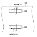
ところで、実施の形態のボトムケーシング52の少なくともリニアモータ40の移動磁界の作用するエリアは、図5、図6の如く錫と親和性のないシリカガラス繊維を主材とした不織布(絶縁材)56により電気的に相互に絶縁された複数のオーステナイト系のステンレス製のケーシング片58、58…を配列して構成されている。したがって、図7の如く、一体構造のケーシング部材によってボトムケーシング100を構成したものと比較し、誘導電流を抑制できるので、図6に示したボトムケーシング52では昇温温度を抑制できる。これにより、ボトム煉瓦50の目地に浸透していた錫の溶融を阻止でき、溶け出した溶融錫との反応によるボトムケーシング52の浸食を阻止できる。また、本発明では、誘導電流によるロスが減少されるため、溶融錫16への駆動力も向上する。なお、水路54は、リニアモータ40の上方に位置するケーシング片58毎に形成されている。
By the way, at least the area of the
図7の一体構造のケーシング部材によって構成されたボトムケーシング100では、大きな誘導電流が発生するため、リニアモータ102に与える電流に制限があったが、実施の形態のボトムケーシング52(図5、図6参照)の誘導電流低減により、リニアモータ40に与える電流を増加させることができ、溶融錫16への駆動力を更に増大させることができる。また、リニアモータ40のパワーをある程度落としても、従来同様の駆動力を得ることができるので、省エネルギ化も図ることができる。
In the
更にまた、短冊状のケーシング片58は図5に示すように、その短辺寸法をW(mm)とし、リニアモータ40のポールピッチをτ(mm)とした際に、誘導電流を十分抑えるためにW≦2τとなる短辺寸法に形成される。また、ケーシング片58は全体形状が短冊状に形成され、図5の太矢印のリニアモータ40による移動磁界の移動方向に対して長辺を略平行に並べて配置されている。
Furthermore, as shown in FIG. 5, the strip-shaped
ケーシング片58の短辺寸法(W)と、リニアモータ40によるケーシング片58の発熱量(kW)とは略比例関係にある。このため、短辺寸法(W)を小さくすればするほど発熱量(kW)を抑えることができるので有利であるが、短辺寸法(W)を小さくするに従ってボトムケーシング52の強度及び施工性が低下する。このため、ケーシング片58の短辺寸法は、W≧80mmが好ましい。
The short side dimension (W) of the
図8は、短辺寸法(W)/ポールピッチ(τ)に対する発熱比の関係を示したグラフであり、この発熱比は、従来の一体型のボトムケーシングでの発熱量を1とした場合における比である。 FIG. 8 is a graph showing the relationship of the heat generation ratio with respect to the short side dimension (W) / pole pitch (τ). This heat generation ratio is obtained when the heat generation amount in the conventional integrated bottom casing is 1. Is the ratio.
図8のグラフによりW/τ≦2とすると、従来と比較し発熱量を70%以下に抑えることが可能となる。好ましくはW/τ≦1、より好ましくはW/τ≦0.5、更に好ましくはW/τ≦0.3である。ここで、ボトムケーシング52の強度及び施工性を考慮すると、Wは80〜150mm、より好ましくは90〜110mmが好適である。例えばW=100mm、τ=348mmの場合、発熱比は従来の一体型のボトムケーシングと比較して約6%となり、またW=100mm、τ=261mmの場合、約10%となる。以上の結果により、ボトムケーシング52の発熱量を大幅に抑えることができる。ケーシング片58の板自体の板厚は3〜10mmが好適である。
If W / τ ≦ 2 in the graph of FIG. 8, the amount of heat generation can be suppressed to 70% or less as compared with the conventional case. Preferably W / τ ≦ 1, more preferably W / τ ≦ 0.5, and still more preferably W / τ ≦ 0.3. Here, considering the strength and workability of the
なお、実施の形態の板ガラス製造装置10では、ボトムケーシング52に水路54が形成された冷却構造を付与し、かつボトムケーシング52を複数のケーシング片58、58…によって構成したが、冷却構造とケーシング片58による分割構造とを個別に構成しても、ボトム煉瓦の目地に浸透していた金属の溶融を阻止でき、溶け出した溶融錫との反応によるボトムケーシングの浸食を阻止できる、と言う同様の効果を達成できる。
In the plate
また、実施の形態では、リニアモータ40の磁界により溶融錫16の浴面24に凹部26を形成し、凹部26に溶融ガラスリボン20の両側エッジ22、22を流入させて板ガラスを製造する製造装置10を例示したが、これに限定されるものではない。すなわち、本発明のフロートガラスの製造装置は、溶融錫が湛えられたフロート法において、ボトムケーシングの下部にリニアモータが設けられた製造装置であれば適用できる。なお、FPD用板ガラスとして要求される板厚、平坦度のガラスを安定して生産するためには、前述した凹部26に両側エッジ22、22を流入させて保持する製造装置10を採択することが好ましい。
Moreover, in embodiment, the recessed
10…板ガラス製造装置、12…樋状体、14…浴槽、16…溶融錫、18…供給口、20…溶融ガラスリボン、22…エッジ、24…浴面、26…凹部、28…入口、30…縦方向流路、32…出口、34…横方向流路、36…貫通孔、38…循環用流路、40…リニアモータ、50…ボトム煉瓦、52…ボトムケーシング、54…水路、56…不織布、58…ケーシング片
DESCRIPTION OF
Claims (7)
前記ボトムケーシングの少なくともリニアモータの移動磁界の作用するエリアは、非磁性体製のボトムケーシングであり、該ボトムケーシングは冷却構造を有することを特徴とするフロートガラスの製造装置。 Bathtub with molten metal, bottom brick of bathtub hearth, bottom casing covering bottom brick on bottom brick, float glass with linear motor for driving molten metal by magnetic field at bottom of bottom casing Manufacturing equipment,
An apparatus for producing float glass, wherein at least an area of the bottom casing on which a moving magnetic field of a linear motor acts is a bottom casing made of a non-magnetic material, and the bottom casing has a cooling structure.
前記ボトムケーシングの少なくともリニアモータの移動磁界の作用するエリアが、絶縁材により電気的に相互に絶縁された複数の非磁性体製のケーシング片によって構成されていることを特徴とするフロートガラスの製造装置。 Bathtub with molten metal, bottom brick of bathtub hearth, bottom casing covering bottom brick on bottom brick, float glass with linear motor for driving molten metal by magnetic field at bottom of bottom casing Manufacturing equipment,
Float glass manufacturing characterized in that at least the area where the moving magnetic field of the linear motor acts on the bottom casing is constituted by a plurality of non-magnetic casing pieces electrically insulated from each other by an insulating material. apparatus.
前記ボトムケーシングの少なくともリニアモータの移動磁界の作用するエリアは、水冷管を有する冷却構造を備えるとともに、絶縁材により電気的に相互に絶縁された複数の非磁性のステンレス製のケーシング片によって構成されていることを特徴とするフロートガラスの製造装置。 Bathtub with molten metal, bottom brick of bathtub hearth, bottom casing covering bottom brick on bottom brick, float glass with linear motor for driving molten metal by magnetic field at bottom of bottom casing Manufacturing equipment,
At least the area where the moving magnetic field of the linear motor acts on the bottom casing is provided with a cooling structure having a water cooling pipe and is composed of a plurality of nonmagnetic stainless steel casing pieces electrically insulated from each other by an insulating material. An apparatus for producing float glass.
Priority Applications (5)
| Application Number | Priority Date | Filing Date | Title |
|---|---|---|---|
| JP2005340131A JP4900773B2 (en) | 2005-11-25 | 2005-11-25 | Float glass manufacturing apparatus and method |
| KR1020087008053A KR100954310B1 (en) | 2005-11-25 | 2006-10-25 | Apparatus for producing float glass and process therefor |
| PCT/JP2006/321301 WO2007060809A1 (en) | 2005-11-25 | 2006-10-25 | Apparatus for producing float glass and process therefor |
| TW095140275A TW200728217A (en) | 2005-11-25 | 2006-10-31 | Apparatus and method for manufacturing float glass |
| US12/124,662 US20080223079A1 (en) | 2005-11-25 | 2008-05-21 | Apparatus and process for producing a float glass |
Applications Claiming Priority (1)
| Application Number | Priority Date | Filing Date | Title |
|---|---|---|---|
| JP2005340131A JP4900773B2 (en) | 2005-11-25 | 2005-11-25 | Float glass manufacturing apparatus and method |
Publications (2)
| Publication Number | Publication Date |
|---|---|
| JP2007145623A JP2007145623A (en) | 2007-06-14 |
| JP4900773B2 true JP4900773B2 (en) | 2012-03-21 |
Family
ID=38067047
Family Applications (1)
| Application Number | Title | Priority Date | Filing Date |
|---|---|---|---|
| JP2005340131A Expired - Fee Related JP4900773B2 (en) | 2005-11-25 | 2005-11-25 | Float glass manufacturing apparatus and method |
Country Status (5)
| Country | Link |
|---|---|
| US (1) | US20080223079A1 (en) |
| JP (1) | JP4900773B2 (en) |
| KR (1) | KR100954310B1 (en) |
| TW (1) | TW200728217A (en) |
| WO (1) | WO2007060809A1 (en) |
Families Citing this family (8)
| Publication number | Priority date | Publication date | Assignee | Title |
|---|---|---|---|---|
| JP2009107914A (en) * | 2007-11-01 | 2009-05-21 | Central Glass Co Ltd | Process for producing float plate glass |
| KR101347774B1 (en) * | 2009-03-03 | 2014-01-07 | 주식회사 엘지화학 | Float bath system for manufacturing glass & cooling method of the same |
| KR101347775B1 (en) * | 2009-03-03 | 2014-01-07 | 주식회사 엘지화학 | Float bath system for manufacturing glass |
| CN102612498B (en) * | 2009-11-16 | 2015-01-07 | 旭硝子株式会社 | Molten glass supply device |
| KR101383605B1 (en) * | 2010-08-11 | 2014-04-11 | 주식회사 엘지화학 | Float bath for manufacturing float glass & cooling method of the same |
| KR101383604B1 (en) * | 2010-08-12 | 2014-04-11 | 주식회사 엘지화학 | Float bath for manufacturing float glass & cooling method of the same |
| CN103635437B (en) * | 2011-08-16 | 2016-07-20 | 旭硝子株式会社 | Float glass manufacturing device and use the float glass making process of this manufacture device |
| CN104114505B (en) * | 2012-02-08 | 2017-04-12 | 旭硝子株式会社 | Plate glass production device, and plate glass production method |
Family Cites Families (14)
| Publication number | Priority date | Publication date | Assignee | Title |
|---|---|---|---|---|
| NL289568A (en) * | 1962-03-01 | 1900-01-01 | ||
| US3393061A (en) * | 1965-10-19 | 1968-07-16 | Ford Motor Co | Method and apparatus for preventing bubbles in float glass apparatus |
| US3486876A (en) * | 1967-05-17 | 1969-12-30 | Ford Motor Co | Composite tweel for chamber utilized in the manufacture of float glass |
| US4197106A (en) * | 1978-09-11 | 1980-04-08 | Ppg Industries, Inc. | Method and apparatus for asymmetric cooling in a glass sheet forming chamber |
| US4415349A (en) * | 1982-04-15 | 1983-11-15 | Owens-Illinois, Inc. | Method and apparatus for cooling glass furnace forehearth |
| US4565557A (en) * | 1983-08-26 | 1986-01-21 | The United States Of America As Represented By The Administrator Of The National Aeronautics And Space Administration | Containerless high purity pulling process and apparatus for glass fiber |
| US5007950A (en) * | 1989-12-22 | 1991-04-16 | Ppg Industries, Inc. | Compressed, wedged float glass bottom structure |
| JP3845935B2 (en) * | 1996-02-29 | 2006-11-15 | 旭硝子株式会社 | Method for holding edge of molten glass flow, glass ribbon forming apparatus and glass plate manufacturing method |
| US5948133A (en) * | 1996-02-29 | 1999-09-07 | Asahi Glass Company Ltd. | Method for holding an edge of a molten glass flow |
| JP3844164B2 (en) * | 1996-12-26 | 2006-11-08 | 旭硝子株式会社 | Sheet glass manufacturing method and manufacturing apparatus |
| US6003337A (en) * | 1996-12-26 | 1999-12-21 | Asahi Glass Company Ltd. | Method and apparatus for producing a sheet glass |
| JP3846026B2 (en) * | 1998-04-27 | 2006-11-15 | 旭硝子株式会社 | Sheet glass manufacturing method and apparatus used for the method |
| JP4174855B2 (en) * | 1998-06-29 | 2008-11-05 | 旭硝子株式会社 | Float plate glass manufacturing apparatus and float plate glass manufacturing method |
| WO2005021450A1 (en) * | 2003-08-29 | 2005-03-10 | Nippon Sheet Glass Company, Limited | Glass melting device and glass melting method |
-
2005
- 2005-11-25 JP JP2005340131A patent/JP4900773B2/en not_active Expired - Fee Related
-
2006
- 2006-10-25 WO PCT/JP2006/321301 patent/WO2007060809A1/en active Application Filing
- 2006-10-25 KR KR1020087008053A patent/KR100954310B1/en not_active IP Right Cessation
- 2006-10-31 TW TW095140275A patent/TW200728217A/en not_active IP Right Cessation
-
2008
- 2008-05-21 US US12/124,662 patent/US20080223079A1/en not_active Abandoned
Also Published As
| Publication number | Publication date |
|---|---|
| KR20080050464A (en) | 2008-06-05 |
| TW200728217A (en) | 2007-08-01 |
| US20080223079A1 (en) | 2008-09-18 |
| KR100954310B1 (en) | 2010-04-21 |
| JP2007145623A (en) | 2007-06-14 |
| TWI377180B (en) | 2012-11-21 |
| WO2007060809A1 (en) | 2007-05-31 |
Similar Documents
| Publication | Publication Date | Title |
|---|---|---|
| JP4900773B2 (en) | Float glass manufacturing apparatus and method | |
| CN105307989A (en) | Float glass production method and float glass production device | |
| JP4725153B2 (en) | Float plate glass manufacturing method and apparatus | |
| JP2007131525A (en) | Process for producing flat glass, particularly float glass easy to become glass ceramic | |
| JP4581877B2 (en) | Method of energizing and heating a depressurization defoaming tank of a depressurization defoaming device, method of energizing and heating a depressurization defoaming device, and depressurization defoaming method, glass manufacturing method, and depressurization defoaming device using them | |
| US20070209395A1 (en) | Method for manufacturing float glass and device therefor | |
| KR100434570B1 (en) | Method for holding an edge of a melt glass flow and a device for forming a glass ribbon | |
| JP5409693B2 (en) | Float tank for glass plate production, method for forming float glass using the same, and method for constructing a barrier in the float tank | |
| JP4339949B2 (en) | Float type glass sheet manufacturing method and apparatus for manufacturing the same | |
| JP4924979B2 (en) | Float plate glass manufacturing apparatus and manufacturing method | |
| JP2006315937A (en) | Sheet glass and method for producing sheet glass | |
| WO2021117618A1 (en) | Melted glass transport device, glass article manufacturing device, and glass article manufacturing method | |
| CN116213692A (en) | Single-flow arc-shaped channel air curtain retaining wall induction heating tundish and pouring method | |
| US3941576A (en) | Method and apparatus for making molten glass with batch guiding means | |
| JP2017014059A (en) | Molten glass supply apparatus, production apparatus of glass sheet, and production methods of glass sheet | |
| JP5267315B2 (en) | Tundish for continuous casting and continuous casting method | |
| JP2019094245A (en) | Float glass production method and float glass | |
| JP2012082107A (en) | Plate glass forming apparatus and method of forming glass sheet | |
| JP4766303B2 (en) | Float plate glass manufacturing apparatus and float plate glass manufacturing method | |
| KR20060123615A (en) | Structure, float sheet glass manufacturing apparatus, bubble floating suppressing method, and float sheet glass manufacturing method | |
| CN105624419A (en) | Vacuum arc remelting furnace | |
| US3941577A (en) | Method and apparatus for making molten glass | |
| JP2007308331A (en) | Float bath | |
| KR20050064935A (en) | Apparatus for rising temperature and damping vortex for molten steel in tundish, and method thereof | |
| JP2000271706A (en) | Twin roll type continuous casting method and device thereof |
Legal Events
| Date | Code | Title | Description |
|---|---|---|---|
| A521 | Request for written amendment filed |
Free format text: JAPANESE INTERMEDIATE CODE: A523 Effective date: 20061024 |
|
| A621 | Written request for application examination |
Free format text: JAPANESE INTERMEDIATE CODE: A621 Effective date: 20081017 |
|
| TRDD | Decision of grant or rejection written | ||
| A01 | Written decision to grant a patent or to grant a registration (utility model) |
Free format text: JAPANESE INTERMEDIATE CODE: A01 Effective date: 20111209 |
|
| A01 | Written decision to grant a patent or to grant a registration (utility model) |
Free format text: JAPANESE INTERMEDIATE CODE: A01 |
|
| A61 | First payment of annual fees (during grant procedure) |
Free format text: JAPANESE INTERMEDIATE CODE: A61 Effective date: 20111222 |
|
| FPAY | Renewal fee payment (event date is renewal date of database) |
Free format text: PAYMENT UNTIL: 20150113 Year of fee payment: 3 |
|
| LAPS | Cancellation because of no payment of annual fees |