JP4898804B2 - Method for detecting device activity in a network of distributed stations and network station for carrying out this method - Google Patents
Method for detecting device activity in a network of distributed stations and network station for carrying out this method Download PDFInfo
- Publication number
- JP4898804B2 JP4898804B2 JP2008520818A JP2008520818A JP4898804B2 JP 4898804 B2 JP4898804 B2 JP 4898804B2 JP 2008520818 A JP2008520818 A JP 2008520818A JP 2008520818 A JP2008520818 A JP 2008520818A JP 4898804 B2 JP4898804 B2 JP 4898804B2
- Authority
- JP
- Japan
- Prior art keywords
- network
- network station
- protocol
- search request
- station
- Prior art date
- Legal status (The legal status is an assumption and is not a legal conclusion. Google has not performed a legal analysis and makes no representation as to the accuracy of the status listed.)
- Expired - Fee Related
Links
Images


Classifications
-
- H—ELECTRICITY
- H04—ELECTRIC COMMUNICATION TECHNIQUE
- H04L—TRANSMISSION OF DIGITAL INFORMATION, e.g. TELEGRAPHIC COMMUNICATION
- H04L12/00—Data switching networks
- H04L12/28—Data switching networks characterised by path configuration, e.g. LAN [Local Area Networks] or WAN [Wide Area Networks]
-
- H—ELECTRICITY
- H04—ELECTRIC COMMUNICATION TECHNIQUE
- H04L—TRANSMISSION OF DIGITAL INFORMATION, e.g. TELEGRAPHIC COMMUNICATION
- H04L12/00—Data switching networks
- H04L12/28—Data switching networks characterised by path configuration, e.g. LAN [Local Area Networks] or WAN [Wide Area Networks]
- H04L12/2803—Home automation networks
- H04L12/2807—Exchanging configuration information on appliance services in a home automation network
-
- H—ELECTRICITY
- H04—ELECTRIC COMMUNICATION TECHNIQUE
- H04L—TRANSMISSION OF DIGITAL INFORMATION, e.g. TELEGRAPHIC COMMUNICATION
- H04L69/00—Network arrangements, protocols or services independent of the application payload and not provided for in the other groups of this subclass
- H04L69/40—Network arrangements, protocols or services independent of the application payload and not provided for in the other groups of this subclass for recovering from a failure of a protocol instance or entity, e.g. service redundancy protocols, protocol state redundancy or protocol service redirection
-
- H—ELECTRICITY
- H04—ELECTRIC COMMUNICATION TECHNIQUE
- H04L—TRANSMISSION OF DIGITAL INFORMATION, e.g. TELEGRAPHIC COMMUNICATION
- H04L67/00—Network arrangements or protocols for supporting network services or applications
- H04L67/01—Protocols
- H04L67/02—Protocols based on web technology, e.g. hypertext transfer protocol [HTTP]
-
- H—ELECTRICITY
- H04—ELECTRIC COMMUNICATION TECHNIQUE
- H04L—TRANSMISSION OF DIGITAL INFORMATION, e.g. TELEGRAPHIC COMMUNICATION
- H04L67/00—Network arrangements or protocols for supporting network services or applications
- H04L67/50—Network services
- H04L67/51—Discovery or management thereof, e.g. service location protocol [SLP] or web services
Landscapes
- Engineering & Computer Science (AREA)
- Computer Networks & Wireless Communication (AREA)
- Signal Processing (AREA)
- Automation & Control Theory (AREA)
- Computer Security & Cryptography (AREA)
- Small-Scale Networks (AREA)
- Computer And Data Communications (AREA)
- Data Exchanges In Wide-Area Networks (AREA)
- Maintenance And Management Of Digital Transmission (AREA)
Abstract
Description
本発明は、ローカルエリアネットワークの技術分野に関し、特にドメスティックネットワーク(domestic network)の技術分野に関する。 The present invention relates to the technical field of a local area network, and more particularly to the technical field of a domestic network.
ドメスティック領域での装置のネットワーキングのために、様々なドメスティックネットワーク標準が利用可能である。Microsoftにより主導される企業(特にコンピュータ業界の企業)の1つのコンソーシアムは、既存のインターネットプロトコル(IP:Internet Protocol)に基づいて、ネットワーク制御ソフトウェアの仕様のイニシアチブを開始している。このネットワークシステムは、略語UPnP(Universal Plug and Play)で知られている。UPnPシステムは、一連の標準的なネットワークプロトコル及びデータフォーマットに基づき、異なる製造者からの装置(PC、ルータ、プリンタ、スキャナ、家庭用娯楽電子装置、白物家電及びビル制御システムの分野での家庭用装置のようなコンピュータ業界からの典型的な装置を含む)を制御するために使用される。“レジデンシャルゲートウェイ(residential gateway)”による中央監視で又は中央監視なしに、装置はIP型ネットワークを介してネットワーク接続される。この場合、ネットワークシステムは、プラグアンドプレイシステムの形式であり、すなわち、ネットワークはユーザとの相互作用なしに構成される。コントロールポイントに対応するコントロールポイント装置は、ネットワークの装置を自発的に見つけることができる。IP通信をサポートする全ての形式の媒体は、例えば、Ethernet(登録商標)、Firewire、Bluetooth及び無線LAN等のような無線伝送システムにより、物理伝送媒体として使用可能である。IP、UDP(ユーザ・データグラム・プロトコルに対応する)、マルチキャスト、TCP(伝送制御プロトコルに対応する)、HTTP(ハイパーテキスト転送プロトコルに対応する)、XML(拡張可能マークアップ言語に対応する)、SOAP(シンプル・オブジェクト・アクセス・プロトコルに対応する)、SSDP(シンプル・サービス・ディスカバリ・プロトコルに対応する)のような標準技術が使用される。 Various domestic network standards are available for networking devices in the domestic domain. One consortium of companies led by Microsoft (especially those in the computer industry) has begun an initiative to specify network control software based on the existing Internet Protocol (IP). This network system is known by the abbreviation UPnP (Universal Plug and Play). UPnP systems are based on a series of standard network protocols and data formats, and are based on devices from different manufacturers (PCs, routers, printers, scanners, home entertainment electronics, home appliances in the field of home appliances and building control systems. Used to control typical equipment from the computer industry, such as industrial equipment). With or without central monitoring by a “residential gateway”, the devices are networked via an IP network. In this case, the network system is in the form of a plug and play system, i.e. the network is configured without interaction with the user. A control point device corresponding to the control point can spontaneously find a device on the network. All types of media that support IP communication can be used as physical transmission media by wireless transmission systems such as Ethernet (registered trademark), Firewire, Bluetooth, and wireless LAN. IP, UDP (corresponding to user datagram protocol), multicast, TCP (corresponding to transmission control protocol), HTTP (corresponding to hypertext transfer protocol), XML (corresponding to extensible markup language), Standard technologies such as SOAP (corresponding to the Simple Object Access Protocol), SSDP (corresponding to the Simple Service Discovery Protocol) are used.
UPnP仕様は、UPnP標準に基づいてどのように装置が設定され、どのように装置が監視可能であるかを記載する。この仕様の基本的な概念の1つは、標準的なウェブブラウザを介して如何なるUPnP装置をも動作することができるという点にある。このため、各UPnP装置は、装置の動作についてのHTMLページ(いわゆるプレゼンテーションページ)が格納されるウェブサーバを有する。 The UPnP specification describes how a device is configured and how the device can be monitored based on the UPnP standard. One of the basic concepts of this specification is that any UPnP device can be operated via a standard web browser. For this reason, each UPnP device has a web server in which an HTML page (so-called presentation page) about the operation of the device is stored.
UPnPネットワークシステムでは、ネットワークの新規の局がログオンしなければならず、切断される局がネットワークからログオフしなければならないという確認処理が実行される。これは、SSDPプロトコルによる特別のメッセージを用いて行われる。UPnP標準は、活動状態を定期的に通知することを個々のネットワーク局に提供する。これは、ネットワーク局が少なくとも1800秒毎に送信しなければならないSSDPメッセージ(特に“ssdp:alive”)を用いて行われる。これは30分の最小セッション期間に対応する。 In the UPnP network system, a confirmation process is executed in which a new station on the network must log on and a station to be disconnected must log off from the network. This is done using special messages according to the SSDP protocol. The UPnP standard provides individual network stations with periodic notification of activity status. This is done using SSDP messages (especially “ssdp: alive”) that the network station must send at least every 1800 seconds. This corresponds to a minimum session duration of 30 minutes.
装置がネットワークを離れると、“ssdp:byebye”という形式のログオフメッセージを送信すべきである。ログオフメッセージが送信されると、コントロールポイント装置は、UPnP装置がネットワークを離れたことを迅速に確認するためにこれを使用することができる。更に、コントロールポイント装置はまた、対応するネットワーク局が非活動状態に切り替わったことを特定するために、所定の繰り返し間隔の後に何らかの活動状態確認メッセージのないことを使用してもよい。実際に、装置が電源オフになるとき、従って、依然として接続されていても基本的にはもはやネットワークに存在しないときに、ssdp:byebyeメッセージを送信することは可能である。しかし、ケーブルを抜くことによりネットワークから切断されると、物理的な理由で前述のログオフメッセージを送信することは不可能である。しかし、監視される最小の期間は30分でかなり長いため、これはユーザにとって予期しない反応を有し得る。特に、ある時間にもはや活動状態ではなくなるように切り替わったが、活動状態確認メッセージが最大許容期間の間にまだ存在しない装置をユーザが使用しようとすると、ネットワークは理想的には応答しない。これは、仮に存在する装置にアクセスするとすぐに、もはや活動状態でないことを検出し、急にユーザメニューから消滅するため、ユーザを混乱させる可能性があるからである。 When a device leaves the network, it should send a logoff message of the form “ssdp: byebye”. Once the logoff message is sent, the control point device can use it to quickly confirm that the UPnP device has left the network. In addition, the control point device may also use the absence of any activity confirmation message after a predetermined repetition interval to identify that the corresponding network station has switched to the inactive state. In fact, it is possible to send an ssdp: byebye message when the device is powered off, and therefore is still connected but basically no longer in the network. However, once disconnected from the network by unplugging the cable, it is impossible to send the logoff message described above for physical reasons. However, this may have an unexpected response for the user, as the minimum period to be monitored is quite long at 30 minutes. In particular, if a user attempts to use a device that has been switched so that it is no longer active at some time, but the activity confirmation message does not yet exist during the maximum allowed period, the network will not ideally respond. This is because, as soon as an existing device is accessed, it is detected that it is no longer active and suddenly disappears from the user menu, which may confuse the user.
本発明の目的は、未確認の装置ログオフメッセージの場合にユーザフレンドリーな応答を提供することにある。 It is an object of the present invention to provide a user friendly response in the case of unconfirmed device logoff messages.
本発明による対策は、コントロールポイント装置が検索要求をネットワーク局に短い時間間隔で定期的に送信することに基づく。これは、UPnP仕様に従って許容され、このような検索要求に最小の時間間隔は存在しない。一例として、検索要求は5秒、10秒又は15秒毎に送信され得る。指定されたネットワーク局は、このような検索要求に応答しなければならない。個々の装置から応答が存在しない場合、コントロールポイント装置は、どの装置がネットワークを離れたかを見つけることができる。 The measure according to the invention is based on the fact that the control point device periodically sends a search request to the network station at short time intervals. This is allowed according to the UPnP specification and there is no minimum time interval for such a search request. As an example, the search request may be sent every 5 seconds, 10 seconds or 15 seconds. The designated network station must respond to such a search request. If there is no response from the individual device, the control point device can find out which device has left the network.
しかし、これに関して、検索要求及び関連する応答の双方はUDPパケットとして送信されることを思い出さなければならない。すなわち、パケットが実際に受信者に到達するという確信はない。UDPは、保護されていないデータ伝送プロトコルである。これは、特に個々の装置が無線リンクを介してネットワークと通信するときに問題になる。この問題は、検索要求への単一の応答のないことは装置が非活動状態であるという仮定を生じず、この仮定は2つ以上の応答のない後でのみ行われるという手法により確かに解決可能である。しかし、次に、このことは、装置が実際にネットワークからログオフしたか否かを特定するのに長い時間を必要とするという欠点を有する。 In this regard, however, it must be remembered that both the search request and the associated response are sent as UDP packets. That is, there is no certainty that the packet will actually reach the recipient. UDP is an unprotected data transmission protocol. This is particularly problematic when individual devices communicate with the network via a wireless link. This problem is certainly solved by the approach that the absence of a single response to a search request does not result in the assumption that the device is inactive, and this assumption is made only after no more than one response. Is possible. However, this in turn has the disadvantage that it takes a long time to determine whether the device has actually logged off the network.
この更なる問題を解決するため、本発明は、検索要求への応答のない場合に、装置が依然として活動状態であるか否かを検査するために誤り保護された伝送プロトコルが更に使用されることを提供する。SSDPプロトコル及びUPnP仕様による装置認識の全章は、確かにこの手段をサポートしておらず、UPnP仕様内で簡単な方法で装置の存在を検査する機能が存在する。仕様によれば、各UPnP装置は、装置に関する情報がアクセス可能なウェブサーバを有する。例えば、この情報は、いわゆる装置記述及びサービス記述を有する。これらは双方共にXMLファイルである。これらのファイルは、専らHTTPプロトコルによりアクセスされる。HTTPプロトコルはTCPプロトコルに基づくため、誤り保護されたプロトコルである。いずれの場合でも、コントロールポイント装置は、UPnP装置の装置記述のURL(ユニフォーム・リソース・ロケータに対応する)を認識している。この理由は、装置がログオンしたときに、これが全てのネットワーク局に送信されるからである。従って、コントロールポイント装置は、検索要求への前述の応答がない場合に、装置記述又は他の既存のファイルへのHTTPアクセスを使用し、装置がネットワークで依然として活動状態であるか否かを決定することができる。代替として、制御要求はまた、制御される装置に送信されてもよく、これもHTTPを介して送信される。HTTPリンクを設定することが可能である場合、装置は依然として活動状態であるが、これがもはや可能でない場合、ネットワークから削除されている。 To solve this further problem, the present invention further uses an error-protected transmission protocol to check whether the device is still active in the absence of a response to a search request. I will provide a. All chapters on device recognition according to the SSDP protocol and UPnP specification certainly do not support this means, and there is a function to check for the presence of the device in a simple way within the UPnP specification. According to the specification, each UPnP device has a web server to which information about the device can be accessed. For example, this information includes so-called device descriptions and service descriptions. Both of these are XML files. These files are accessed exclusively by the HTTP protocol. Since the HTTP protocol is based on the TCP protocol, it is an error-protected protocol. In any case, the control point device recognizes the device description URL (corresponding to the uniform resource locator) of the UPnP device. This is because when a device logs on, it is sent to all network stations. Thus, if there is no such response to the search request, the control point device uses HTTP access to the device description or other existing file to determine whether the device is still active on the network. be able to. Alternatively, the control request may also be sent to the controlled device, which is also sent via HTTP. If it is possible to set up an HTTP link, the device is still active, but if this is no longer possible, it has been removed from the network.
従って、このことは、前述のユーザフレンドリーな応答を克服する。 This thus overcomes the aforementioned user-friendly response.
本発明による方法及び本発明による装置の有利な発展及び改善は、従属項に記載の手段を用いて可能である。 Advantageous developments and improvements of the method according to the invention and the device according to the invention are possible with the measures described in the dependent claims.
HTTPヘッド(head)アクセスがデータアクセスに使用される場合、最小量のデータのみが転送されればよいという利点を有する。活動状態の検査が制御要求を送信することにより実行される場合、HTTPポストメッセージを使用することが有利である。この場合、制御要求が指定された装置の状態を変更しないことも有利である。 When HTTP head access is used for data access, it has the advantage that only a minimum amount of data needs to be transferred. If the activity check is performed by sending a control request, it is advantageous to use an HTTP post message. In this case, it is also advantageous not to change the state of the device for which the control request is specified.
以下の説明で本発明の例示的な実施例を詳細に説明し、また図面に示す。 In the following description, exemplary embodiments of the invention are described in detail and shown in the drawings.
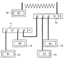
図1は、5つのネットワーク局12-16と、2つのネットワーク接続切り替えユニット10、11とを有するドメスティックネットワークの例を示している。ネットワーク接続切り替えユニット10、11とネットワーク局12-15との間のバス接続はEthernet(登録商標)技術に基づき、特に100Base/TX Ethernet(登録商標)に基づく。ネットワーク局16は、有線を使用せずに、例えばIEEE802.11bに従って無線LANを介してネットワーク接続切り替えユニット10に接続される。2つのネットワーク接続切り替えユニット10及び11の間の接続もまたEthernet(登録商標)技術に基づく。4つのネットワーク接続点(ポートとも呼ばれる)がネットワーク接続切り替えユニット10、11毎に図示されている。図面は、個々のネットワーク局のEthernet(登録商標)インタフェース又はネットワーク接続切り替えユニットのEthernet(登録商標)インタフェースを図示していない。
FIG. 1 shows an example of a domestic network having five network stations 12-16 and two network
導入部で前述したEthernet(登録商標)バスシステムの100Base/TXの変形は、ネットワークでのデータ伝送用の伝送システムとして使用される。この変形は、選択された用途に適していると考えられているが、他の用途では異なる変形が伝送システムとして使用可能である。一例として、いわゆる100Base/T又は1000Base/SX若しくは1000Base/LXが高データレート用に利用可能である。最後の2つの変形は、この場合に光ファイバ技術に基づく。図1に示すネットワークはUPnP型であり、すなわち、個々のネットワーク局はUPnP標準に従って設計される。 The 100Base / TX variant of the Ethernet (registered trademark) bus system described above in the introduction section is used as a transmission system for data transmission in a network. This variant is considered suitable for the chosen application, but different variants can be used for the transmission system in other applications. As an example, so-called 100Base / T or 1000Base / SX or 1000Base / LX can be used for high data rates. The last two variants are based on fiber optic technology in this case. The network shown in FIG. 1 is of the UPnP type, i.e. individual network stations are designed according to the UPnP standard.
Ethernet(登録商標)バスシステムは、伝送フレームが失われる可能性があるため、上位プロトコルレイヤに保護されたリンクを提供しない。このことは、大量のユーザデータの伝送には適していない。そのため、伝送は、上位プロトコルレイヤを用いてしばしば保護される。UPnPネットワークシステムでは、IPプロトコルが次に上位のプロトコルレベルとして提供され、データ通信用のOSIレイヤモデルのネットワークレイヤレベルでのインターネットプロトコルに対応する。データリンクレイヤはTCPプロトコルのみによって実装され、TCPプロトコルはこれを基礎とする。双方のプロトコルレベルに特有の標準が存在し、これらはもはやEthernet(登録商標)標準の構成要素ではなく、本発明の開示に関して言及される。 The Ethernet bus system does not provide a protected link to the upper protocol layer because transmission frames can be lost. This is not suitable for transmitting a large amount of user data. As such, transmissions are often protected using higher protocol layers. In the UPnP network system, the IP protocol is provided as the next higher protocol level and corresponds to the Internet protocol at the network layer level of the OSI layer model for data communication. The data link layer is implemented only by the TCP protocol, which is based on it. There are standards specific to both protocol levels, which are no longer a component of the Ethernet standard, but are mentioned with respect to the present disclosure.
改良したプロトコルスタックが、UPnPネットワークを使用する通信の個々のネットワーク局に必要になる。このプロトコルスタックは図2に図示されている。2つのEthernet(登録商標)プロトコルレベル(Ethernet(登録商標) PHY及びEthernet(登録商標) MAC)が最も下位のレベルに配置される。前述したプロトコルレベルIPがこの上にある。UDPプロトコルもトランスポートレイヤレベルに配置され、装置識別(装置ディスカバリ)に関連する全てのメッセージの伝送に使用される。特別版のHTTPプロトコルがこの上に存在する。これはHTTPMUプロトコル(HTTP Multicast Over UDP)である。このようなHTTPメッセージは、下位のUDP及びIPプロトコルレベルを介して比例配分で(pro rata basis)渡されて指定される。 An improved protocol stack is required for individual network stations for communications using UPnP networks. This protocol stack is illustrated in FIG. Two Ethernet® protocol levels (Ethernet® PHY and Ethernet® MAC) are placed at the lowest level. This is the protocol level IP mentioned above. The UDP protocol is also arranged at the transport layer level and is used for transmission of all messages related to device identification (device discovery). A special version of the HTTP protocol exists on top of this. This is the HTTPMU protocol (HTTP Multicast Over UDP). Such HTTP messages are passed and specified on a pro rata basis via lower UDP and IP protocol levels.
SSDPプロトコルもHTTPMUプロトコルレベルの上に提供される。UDPプロトコルに加えて、TCPプロトコルも使用される。TCPプロトコルは、装置制御及びイベント伝達のための全ての他のUPnPメッセージ(特に装置及びサービス記述)の伝送を目的としている。HTTPプロトコルがこの上にあり、SOAPプロトコルがこの上のSSDPプロトコルレベルにある。SOAPプロトコルは、これまでにシンプル・オブジェクト・アクセス・プロトコルと呼ばれている。これは、他の装置の関数呼び出し(遠隔手続き呼び出し(RPC:remote procedure call)に対応する)を実行するために使用可能である。更に、GENAプロトコル(General Event Notification Architectureに対応する)も実装され、これは、他のネットワーク局でのイベントメッセージの登録を可能にする。 The SSDP protocol is also provided on top of the HTTPMU protocol level. In addition to the UDP protocol, the TCP protocol is also used. The TCP protocol is intended for the transmission of all other UPnP messages (especially device and service descriptions) for device control and event transmission. The HTTP protocol is above this, and the SOAP protocol is above the SSDP protocol level. The SOAP protocol has been called the simple object access protocol. This can be used to execute other device function calls (corresponding to remote procedure calls (RPC)). In addition, the GENA protocol (corresponding to General Event Notification Architecture) is also implemented, which allows event messages to be registered with other network stations.
UPnPネットワークシステムで使用される完全なプロトコルアーキテクチャは、UPnP仕様に見つかり得る(www.upnp.orgを介して取得可能である)。 The complete protocol architecture used in the UPnP network system can be found in the UPnP specification (available via www.upnp.org).
UPnPの標準化の過程で、ネットワーク加入者局の間でAVデータ(オーディオ/ビデオデータ)の伝送のための仕様もまた行われており、これは2002年6月に完了している。この仕様の正確な題名は、2002年6月12日のUPnP-AV-Architecture:0.83である。この仕様では、AVデータの伝送のために3つの異なる種類の装置が規定されている。第1に、いわゆるメディアサーバであり、すなわち、AVデータのソースとして選択された装置である。第2に、メディアレンダラ装置形式が存在し、AVデータのデータシンクとして使用される装置を表す。第3に、コントロールポイント形式も特定の装置形式として提供され、以下の本文ではコントロールポイント装置と呼ばれる。通常では、例えばAV装置用のユニバーサルリモコンがコントロールポイント装置として使用される。しかし、代替として、パーソナルコンピュータもネットワークでこのタスクを実行することができる。或いは、リモコンを有するTVも同様にコントロール装置として使用するのに適することがある。 In the process of UPnP standardization, specifications for the transmission of AV data (audio / video data) between network subscriber stations are also being made, which was completed in June 2002. The exact title of this specification is UPnP-AV-Architecture: 0.83 on June 12, 2002. In this specification, three different types of devices are defined for the transmission of AV data. First, it is a so-called media server, that is, a device selected as a source of AV data. Second, the media renderer device format exists and represents a device used as a data sink for AV data. Third, a control point format is also provided as a specific device format, referred to as a control point device in the text below. Usually, for example, a universal remote controller for an AV device is used as a control point device. However, alternatively, a personal computer can perform this task over the network. Alternatively, a TV with a remote control may be suitable for use as a control device as well.
コントロールポイント装置は、2つの更なるUPnP装置と通信する。2つの更なるUPnP装置は、所望のAVリンクのデータソース及びデータシンクとして使用可能である。コントロールポイント装置は、AVリンクの双方の装置を初期化して構成し、これにより、所望のデータストリームもそれを適用され得る。従って、コントロールポイント装置のタスクは、典型的には2つのネットワーク加入者の間のAVリンクを設定することであり、場合によっては2つの装置の設定を変更することである。また、所望のデータストリームが伝送されると、再びリンクを制限すること、すなわち、そのリンクを特徴付けるデータを削除するようにAVリンクの2つの装置に要求することである。 The control point device communicates with two further UPnP devices. Two additional UPnP devices can be used as the data source and data sink for the desired AV link. The control point device initializes and configures both devices of the AV link so that the desired data stream can be applied as well. Thus, the task of the control point device is typically to set up an AV link between two network subscribers, and in some cases to change the settings of the two devices. Also, once the desired data stream is transmitted, it is to restrict the link again, i.e. to request the two devices of the AV link to delete the data characterizing the link.
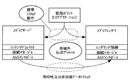
図3は、AVリンクに必要なネットワーク局の基本的な分析を示している。メディアサーバ装置は、例えばローカルに格納されたAVデータストリーム又は外部から受信したAVデータストリームを保持又はアクセスする。メディアサーバ装置は、AVデータにアクセスし、ネットワークを介して他のネットワーク局に関連するAVデータストリームを伝送することができる。この場合に、AVデータストリームは、ネットワークで使用される伝送媒体に適した伝送プロトコルを使用して送信される。メディアサーバによりサポートされるデータ伝送フォーマットは、可能なリソース毎にコンテンツディレクトリサービスに明示的に規定されている。典型的には、メディアサーバ装置形式は以下の装置のうち1つに関連し得る。すなわち、デジタルビデオレコーダ、CD/DVDプレイヤ、カメラ、ビデオカメラ、PC、セットトップボックス、衛星受信機、カセットレコーダ等である。通常では、コンテンツディレクトリ用のモジュールは、UPnP標準に従って特定のAVコンテンツを選択するメディアサーバに実装される。更に、接続マネージャと呼ばれるモジュールも存在し、制御ポイント装置は、リンクを設定する間に、この接続マネージャを用いてメディアレンダラと通信する。 FIG. 3 shows a basic analysis of the network stations required for the AV link. The media server device holds or accesses, for example, a locally stored AV data stream or an externally received AV data stream. The media server device can access AV data and transmit AV data streams related to other network stations via the network. In this case, the AV data stream is transmitted using a transmission protocol suitable for a transmission medium used in the network. The data transmission format supported by the media server is explicitly defined in the content directory service for each possible resource. Typically, the media server device type may be associated with one of the following devices: That is, a digital video recorder, a CD / DVD player, a camera, a video camera, a PC, a set top box, a satellite receiver, a cassette recorder, and the like. Normally, a module for a content directory is mounted on a media server that selects specific AV content according to the UPnP standard. There is also a module called a connection manager, and the control point device uses this connection manager to communicate with the media renderer while setting up the link.
メディアレンダラ装置は、メディアサーバから送信されたAVデータストリームを受信し、ビデオ情報又はオーディオ情報としてこれを出力する。同様に、メディアレンダラ装置は、リンクを設定するときに、コントロールポイント装置と通信する接続マネージャモジュールの実装を有する。レンダリング制御のモジュールもメディアレンダラ装置に実装される。このモジュールは、音量、音質、画像鮮明度、コントラスト、輝度、色度等のような再生特性を調整するコマンドを受信し、これらを実施する。TV、ステレオアンプ及びMP3プレイヤが、ドメスティックネットワークでメディアレンダラ装置形式が割り当てられる装置の例として言及される。実装される伝送フォーマットに応じて、メディアサーバ又はメディアレンダラもAVトランスポートサービスを有する。AVトランスポートサービスは、データ伝送及び再生(例えば、再生、停止、早送り等)を制御するために使用される。コントロールポイント装置は、メディアサーバとメディアレンダラとの間のデータ伝送を調整する。同様に、これは、オペレータによる制御コマンドを実施し、これらをAVリンクの適切な装置に渡すために使用される。この例は、特に、再生、停止、一時停止、早送り、巻き戻しのようなコマンドを含む。導入部で前述したように、コントロールポイント装置も、標準UPnP装置を見つけて制御するように設計される。このことについて以下の本文で詳細に説明する。まず、UPnP装置の標準ソフトウェアコンポーネントについて図4を参照して説明する。参照符号35は、プロトコルスタックを示しており、Ethernet(登録商標)、IP及びTCPのプロトコルスタックを有する。参照符号31は、UPnP装置記述がUPnP装置記述に従って格納されるソフトウェアコンポーネントに対応する。参照符号32は、イベントメッセージが管理され、UPnPイベントに対応するソフトウェアコンポーネントを示す。UPnP装置の1つの標準的な構成要素はまた、ウェブサーバ33である。参照符号34は、UPnPディスカバリユニットを示す。これにより、以下に詳細に説明するように、UPnPコントロールポイント装置がネットワークの他の装置を特定することが可能になる。UPnPアプリケーションプログラムもこれらのブロックの上の参照符号30により示される。全てのこれらのユニットはUPnP装置の標準構成要素であり、UPnP仕様に詳細に記載されている。
The media renderer receives the AV data stream transmitted from the media server and outputs it as video information or audio information. Similarly, the media renderer device has an implementation of a connection manager module that communicates with the control point device when setting up a link. A rendering control module is also implemented in the media renderer device. This module receives and implements commands to adjust playback characteristics such as volume, sound quality, image definition, contrast, brightness, chromaticity, etc. TVs, stereo amplifiers and MP3 players are mentioned as examples of devices to which the media renderer device type is assigned in a domestic network. Depending on the implemented transmission format, the media server or media renderer also has an AV transport service. AV transport services are used to control data transmission and playback (eg, playback, stop, fast forward, etc.). The control point device coordinates data transmission between the media server and the media renderer. Similarly, it is used to implement control commands by the operator and pass them to the appropriate device on the AV link. This example includes commands such as play, stop, pause, fast forward, rewind, among others. As mentioned earlier in the introduction, the control point device is also designed to find and control standard UPnP devices. This will be explained in detail in the following text. First, standard software components of the UPnP apparatus will be described with reference to FIG.
UPnPディスカバリユニットは、UPnP装置が見つけられた場合にのみ制御されることが可能になるため、UPnP装置がネットワークで見つけられることを可能にするために使用される。基本的には、このユニットは以下のように動作する。 The UPnP discovery unit is used to allow UPnP devices to be found on the network because it can only be controlled if a UPnP device is found. Basically, this unit operates as follows.
装置は、いわゆるマルチキャストUDPパケットとして“ディスカバリメッセージ”を送信する。前述のHTTPMUプロトコルがこの目的に使用される。マルチキャストデータパケットは、基本的にはネットワークの全ての装置に送信されるという点で区別される。個々のネットワーク局は、このようなマルチキャストパケットの受信用の特定のアドレスを登録することができる。基本的には、2つの種類のディスカバリメッセージが存在する。
1.いわゆる広告メッセージ。装置がネットワークに連結されるとすぐに、広告メッセージを送信する。SSDPプロトコルによれば、これは“ssdp:alive”メッセージである。これは、この装置がネットワークで現在活動状態であることをネットワークの他の装置に通知する。しかし、装置がネットワークで自分を紹介すると、これらの広告メッセージを定期的に送信する。コントロールポイント装置は、その装置がネットワークから削除されたことを特定するために、広告メッセージのないことを使用し得る。広告メッセージの繰り返し送信の最大セッション期間は1800秒であり、すなわち、30分である。
2.装置を検索するための検索メッセージ。コントロールポイント装置は、検索要求を送信することができる。SSDPプロトコルに従って“ssdp:discover”メッセージがこの目的に使用される。このようなメッセージを受信したUPnP装置は、これに応答しなければならず、これにより、存在することを送信者に通知する。
3.最後に、第3の種類の広告メッセージについても言及される。いわゆるログオフメッセージである。ログオフメッセージは、SSDPプロトコルに従って“sddp:byebye”と呼ばれる。これらは、ネットワークから削除されているときに、装置により送信されることを目的とする。実際に、装置は、通常の方法で電源オフされたときに、これを行うことができる。ネットワークケーブルを抜くことによりネットワークから切断された場合には、物理的な理由でログオフメッセージを送信することはできない。
The device transmits a “discovery message” as a so-called multicast UDP packet. The HTTPMU protocol described above is used for this purpose. A multicast data packet is basically distinguished in that it is transmitted to all devices in the network. Each network station can register a specific address for receiving such multicast packets. Basically, there are two types of discovery messages.
1. So-called advertising message. As soon as the device is connected to the network, it sends an advertising message. According to the SSDP protocol, this is an “ssdp: alive” message. This notifies other devices in the network that this device is currently active in the network. However, when the device introduces itself on the network, it periodically sends these advertising messages. The control point device may use no advertisement message to identify that the device has been removed from the network. The maximum session duration for repeated transmission of advertising messages is 1800 seconds,
2. Search message to search for devices. The control point device can transmit a search request. The “ssdp: discover” message is used for this purpose according to the SSDP protocol. A UPnP device that receives such a message must respond to this, thereby notifying the sender that it exists.
3. Finally, a third type of advertising message is also mentioned. This is a so-called logoff message. The logoff message is called “sddp: byebye” according to the SSDP protocol. These are intended to be sent by the device when it is deleted from the network. In fact, the device can do this when it is powered off in the normal way. When disconnected from the network by disconnecting the network cable, the logoff message cannot be transmitted for physical reasons.
分散局のネットワークで装置の活動状態を検出するための本発明による方法の一実施例について、図5を参照して説明する。 One embodiment of the method according to the invention for detecting device activity in a network of distributed stations is described with reference to FIG.
図5は、この目的でコントロールポイント装置で動作するプログラムのフローチャートを示している。プログラムの開始は、参照符号50で提供される。参照符号51は、検査を示し、ssdp:byebyeメッセージがテストされる装置に既に到達しているか否かに関する検査が実行される。到達している場合には、更なる処理ステップ52〜55は実行される必要が無く、プログラムは直接ステップ56にジャンプする。ステップ56において、当該装置がネットワークからログオフしたものとして分類される。プログラムはプログラムのステップ58で終了する。当該装置のログオフメッセージが検査51で見つからなかった場合、プログラムのステップ52において、当該装置の検索要求が続く。このため、コントロールポイント装置は、ssdp:discoverメッセージを当該装置に送信する。検索要求が指定されたネットワーク局により特定の期間内に応答されたか否かの質問53が検査される。応答された場合、プログラムのステップ57において、ネットワーク局は活動状態のネットワーク局であると宣言される。この場合、適切なエントリがネットワーク局のテーブルに設定され得る。プログラムは、プログラムのステップ58で再び終了する。
FIG. 5 shows a flowchart of a program operating on the control point device for this purpose. The start of the program is provided with
質問53において、検索要求への応答が受信されないことが検出されると、プログラムのステップ54において、当該ネットワーク局の装置記述でXMLドキュメントへのHTTPアクセスが行われる。このファイルのURLは、そのネットワーク局がログオンしたときに通知されているため、コントロールポイント装置は、関連のテーブルのみからこの情報を取得することができる。HTTPヘッド呼び出しの例は以下のように構成される。
Head /upnp/device_description.xml HTTP/1.1
Host:ローカルIPアドレス 局3
代替として、HTTP get呼び出しが行われてもよい。
If it is detected in
Head /upnp/device_description.xml HTTP / 1.1
Host: Local IP address Station 3
Alternatively, an HTTP get call may be made.
一例として、UPnPコマンド取得状態は、制御要求として、HTTPポストアクセスによりネットワーク局に送信され得る。質問55は、所望のファイルが返信されたか否かを検査する。当該局が非活動状態である場合、それに対してTCPリンクを設定することは不可能である。当該ネットワーク局は、このことからHTTPアクセスが失敗したことをまさに特定する。次に、プログラムのステップ56において、ネットワーク局がネットワークからログオフしたという事実又はネットワークで非活動状態になったという事実を通知するために、ネットワーク局のテーブルのエントリにより後続される。この後に、プログラムはプログラムのステップ58で再び終了する。
As an example, the UPnP command acquisition state can be transmitted to the network station by HTTP post access as a control request.
Claims (17)
1つのネットワーク局の活動状態は、パケットロスに対して保護されていない伝送プロトコルを用いてネットワーク局への検索要求により検査され、
パケットの配信が保証される少なくとも1つの安全な伝送プロトコルがデータアクセス及び/又はネットワーク局の制御のために利用可能になり、
調べられるネットワーク局が前記検索要求に応答しない場合、このネットワーク局へのデータアクセス及び/又は制御要求が、前記安全な伝送プロトコルを用いて更に行われ、
前記データアクセス及び/又は前記制御要求が失敗したという事実が前記安全な伝送プロトコルを介して伝達された場合に、指定されたネットワーク局の非活動状態が確認されることを特徴とする方法。A method for detecting device activity in a network of distributed stations, comprising:
The activity status of one network station is checked by a search request to the network station using a transmission protocol that is not protected against packet loss ,
At least one secure transmission protocol that guarantees the delivery of packets is available for data access and / or control of network stations;
If the network station being examined does not respond to the search request, a data access and / or control request to this network station is further made using the secure transmission protocol,
A method wherein the inactive state of a designated network station is confirmed when the fact that the data access and / or the control request has failed is communicated via the secure transmission protocol.
前記データアクセスは、そのネットワーク局に利用可能になっている情報ファイルに対して行われる、請求項1に記載の方法。 Control function of the network stations controlled is available in the form of one or more information files,
The method of claim 1, wherein the data access is to an information file made available to the network station.
通信インタフェースを有し、
分散局のネットワークで更なるネットワーク局の活動状態を検査する活動状態検査手段を有し、
前記活動状態検査手段は、分散局のネットワークで前記更なるネットワーク局の検索要求を生成し、これをパケットロスに対して保護されていない伝送プロトコルを用いて送信する検索要求手段を有し、
データアクセス及び/又は前記更なるネットワーク局の制御のためにパケットの配信が保証される少なくとも1つの安全な伝送プロトコルを利用可能にする通信手段が提供され、
前記活動状態検査手段は、前記検索要求への応答が存在しない場合に、前記通信手段を使用し、前記更なるネットワーク局のデータアクセス及び/又は制御要求を試み、
前記活動状態検査手段は、前記データアクセス及び/又は前記制御要求への反応を評価し、前記データアクセス及び/又は前記制御要求が失敗したという事実が前記安全な伝送プロトコルを介して伝達された場合に、前記指定された更なるネットワーク局の非活動状態を確認する評価手段を有することを特徴とするネットワーク局。A network station for performing the method according to any one of claims 1 to 11, comprising:
A communication interface,
An active state inspection means for inspecting the active state of further network stations in the network of distributed stations;
The activity state checking means includes search request means for generating a search request for the further network station in a network of distributed stations and transmitting the request using a transmission protocol that is not protected against packet loss ,
A communication means is provided that makes available at least one secure transmission protocol that ensures delivery of packets for data access and / or control of said further network station;
The activity checking means, when there is no response to the search request, uses the communication means to attempt a data access and / or control request of the further network station;
The activity checking means evaluates the response to the data access and / or the control request, and the fact that the data access and / or the control request has failed is communicated via the secure transmission protocol The network station further comprises evaluation means for confirming the inactive state of the designated additional network station.
Applications Claiming Priority (3)
| Application Number | Priority Date | Filing Date | Title |
|---|---|---|---|
| DE102005033211A DE102005033211A1 (en) | 2005-07-13 | 2005-07-13 | Method for determining the activity of a device in a network of distributed stations and network station for carrying out the method |
| DE102005033211.0 | 2005-07-13 | ||
| PCT/EP2006/062879 WO2007006611A1 (en) | 2005-07-13 | 2006-06-02 | Method for detection of the activity of a device in a network of distributed stations, as well as a network station for carrying out the method |
Publications (3)
| Publication Number | Publication Date |
|---|---|
| JP2009501371A JP2009501371A (en) | 2009-01-15 |
| JP2009501371A5 JP2009501371A5 (en) | 2009-07-16 |
| JP4898804B2 true JP4898804B2 (en) | 2012-03-21 |
Family
ID=36790911
Family Applications (1)
| Application Number | Title | Priority Date | Filing Date |
|---|---|---|---|
| JP2008520818A Expired - Fee Related JP4898804B2 (en) | 2005-07-13 | 2006-06-02 | Method for detecting device activity in a network of distributed stations and network station for carrying out this method |
Country Status (8)
| Country | Link |
|---|---|
| US (1) | US8335818B2 (en) |
| EP (1) | EP1902569B1 (en) |
| JP (1) | JP4898804B2 (en) |
| KR (1) | KR101271261B1 (en) |
| CN (1) | CN101218805B (en) |
| AT (1) | ATE422780T1 (en) |
| DE (2) | DE102005033211A1 (en) |
| WO (1) | WO2007006611A1 (en) |
Families Citing this family (13)
| Publication number | Priority date | Publication date | Assignee | Title |
|---|---|---|---|---|
| US20070162755A1 (en) * | 2006-01-09 | 2007-07-12 | Nokia Corporation | Enhancements for discovering device owners in a UPnP searching service |
| US8788888B2 (en) * | 2008-03-14 | 2014-07-22 | Telefonaktiebolaget L M Ericsson (Publ) | Method and apparatus for providing end user notification in a UPnP network |
| KR101718889B1 (en) * | 2008-12-26 | 2017-03-22 | 삼성전자주식회사 | Method and apparatus for providing a device with remote application in home network |
| US8060560B2 (en) * | 2009-08-27 | 2011-11-15 | Net Power And Light, Inc. | System and method for pervasive computing |
| KR101702417B1 (en) | 2009-11-09 | 2017-02-06 | 삼성전자주식회사 | Method and apparatus for monopolizing call session of transmitting/receiving call system using universal plug and play |
| WO2012007665A1 (en) * | 2010-07-15 | 2012-01-19 | France Telecom | DETECTION OF A UPnP CONTROL MODULE |
| US10620797B2 (en) | 2012-06-29 | 2020-04-14 | Spotify Ab | Systems and methods for multi-context media control and playback |
| US9195383B2 (en) * | 2012-06-29 | 2015-11-24 | Spotify Ab | Systems and methods for multi-path control signals for media presentation devices |
| US9628542B2 (en) * | 2012-08-24 | 2017-04-18 | Akamai Technologies, Inc. | Hybrid HTTP and UDP content delivery |
| US9853875B1 (en) * | 2013-06-25 | 2017-12-26 | Google Inc. | Methods, systems, and media for detecting the presence of a digital media device on a network |
| CN104038480B (en) * | 2014-05-20 | 2017-11-10 | 北京奇艺世纪科技有限公司 | Method for discovering equipment and system in a kind of UPnP systems |
| US10237320B2 (en) | 2015-05-15 | 2019-03-19 | Spotify Ab | Playback of an unencrypted portion of an audio stream |
| CN115277477B (en) * | 2022-07-24 | 2024-03-01 | 杭州迪普科技股份有限公司 | Flow detection method and device based on simple object access protocol |
Citations (3)
| Publication number | Priority date | Publication date | Assignee | Title |
|---|---|---|---|---|
| JP2002152204A (en) * | 2000-11-15 | 2002-05-24 | Hitachi Information Systems Ltd | Network supervisory device and method and network supervisory program |
| JP2002330191A (en) * | 2001-05-01 | 2002-11-15 | Ntt Docomo Inc | Method and system for detecting abnormality |
| JP2003067264A (en) * | 2001-08-23 | 2003-03-07 | Hitachi Ltd | Monitor interval control method for network system |
Family Cites Families (17)
| Publication number | Priority date | Publication date | Assignee | Title |
|---|---|---|---|---|
| DK1145541T3 (en) * | 1998-11-24 | 2013-03-11 | Niksun Inc | Apparatus and method for collecting and analyzing communication data |
| FI110226B (en) * | 1999-10-28 | 2002-12-13 | Nokia Corp | subscriber information |
| US6708239B1 (en) * | 2000-12-08 | 2004-03-16 | The Boeing Company | Network device interface for digitally interfacing data channels to a controller via a network |
| US20020078161A1 (en) | 2000-12-19 | 2002-06-20 | Philips Electronics North America Corporation | UPnP enabling device for heterogeneous networks of slave devices |
| US7092999B2 (en) | 2002-06-10 | 2006-08-15 | Gutman Levitan | Data broadcast network for congestion-free internet access |
| US20040073609A1 (en) * | 2002-07-03 | 2004-04-15 | Brother Kogyo Kabushiki Kaisha | Information output system |
| DE10250102A1 (en) * | 2002-10-28 | 2004-07-15 | Deutsche Thomson-Brandt Gmbh | Procedure for the management of established logical connections in a network of distributed stations and network station |
| US7295119B2 (en) * | 2003-01-22 | 2007-11-13 | Wireless Valley Communications, Inc. | System and method for indicating the presence or physical location of persons or devices in a site specific representation of a physical environment |
| KR100533667B1 (en) * | 2003-04-15 | 2005-12-05 | 삼성전자주식회사 | Efficient home network management system and method |
| KR100493898B1 (en) * | 2003-04-16 | 2005-06-10 | 삼성전자주식회사 | Network device, system and method for providing list of controlled device |
| FI20031260A (en) * | 2003-09-04 | 2005-03-05 | Nokia Corp | Streaming media from a server to a customer device |
| KR20050040166A (en) * | 2003-10-27 | 2005-05-03 | 삼성전자주식회사 | Proxy for controlling device of home-network and method thereof |
| US20050108331A1 (en) | 2003-10-31 | 2005-05-19 | Osterman Lawrence W. | Presence tracking for datagram based protocols with search |
| JP4125223B2 (en) * | 2003-12-09 | 2008-07-30 | キヤノン株式会社 | COMMUNICATION DEVICE, IMAGING DEVICE, ITS CONTROL METHOD, AND NETWORK SYSTEM |
| US7647385B2 (en) * | 2003-12-19 | 2010-01-12 | Microsoft Corporation | Techniques for limiting network access |
| US7668939B2 (en) * | 2003-12-19 | 2010-02-23 | Microsoft Corporation | Routing of resource information in a network |
| US8548482B2 (en) * | 2007-10-22 | 2013-10-01 | Intel Mobile Communications GmbH | Radio communication device and method for controlling frequency selection |
-
2005
- 2005-07-13 DE DE102005033211A patent/DE102005033211A1/en not_active Withdrawn
-
2006
- 2006-06-02 US US11/988,777 patent/US8335818B2/en active Active
- 2006-06-02 DE DE602006005155T patent/DE602006005155D1/en active Active
- 2006-06-02 WO PCT/EP2006/062879 patent/WO2007006611A1/en not_active Application Discontinuation
- 2006-06-02 CN CN2006800249164A patent/CN101218805B/en not_active Expired - Fee Related
- 2006-06-02 EP EP06763494A patent/EP1902569B1/en not_active Not-in-force
- 2006-06-02 AT AT06763494T patent/ATE422780T1/en not_active IP Right Cessation
- 2006-06-02 KR KR1020077029443A patent/KR101271261B1/en active IP Right Grant
- 2006-06-02 JP JP2008520818A patent/JP4898804B2/en not_active Expired - Fee Related
Patent Citations (3)
| Publication number | Priority date | Publication date | Assignee | Title |
|---|---|---|---|---|
| JP2002152204A (en) * | 2000-11-15 | 2002-05-24 | Hitachi Information Systems Ltd | Network supervisory device and method and network supervisory program |
| JP2002330191A (en) * | 2001-05-01 | 2002-11-15 | Ntt Docomo Inc | Method and system for detecting abnormality |
| JP2003067264A (en) * | 2001-08-23 | 2003-03-07 | Hitachi Ltd | Monitor interval control method for network system |
Also Published As
| Publication number | Publication date |
|---|---|
| WO2007006611A1 (en) | 2007-01-18 |
| US20090210525A1 (en) | 2009-08-20 |
| KR20080031865A (en) | 2008-04-11 |
| JP2009501371A (en) | 2009-01-15 |
| CN101218805A (en) | 2008-07-09 |
| KR101271261B1 (en) | 2013-06-07 |
| US8335818B2 (en) | 2012-12-18 |
| DE602006005155D1 (en) | 2009-03-26 |
| CN101218805B (en) | 2012-04-25 |
| EP1902569B1 (en) | 2009-02-11 |
| EP1902569A1 (en) | 2008-03-26 |
| DE102005033211A1 (en) | 2007-01-18 |
| ATE422780T1 (en) | 2009-02-15 |
Similar Documents
| Publication | Publication Date | Title |
|---|---|---|
| JP4898804B2 (en) | Method for detecting device activity in a network of distributed stations and network station for carrying out this method | |
| JP4041118B2 (en) | Gateway device, network system, communication program, and communication method | |
| US8774183B2 (en) | Relay device and method for connecting client apparatus with server | |
| US20040120344A1 (en) | Device discovery application interface | |
| KR101037941B1 (en) | Apparatus and method for sharing contents inter-home using a homenetwork devcie | |
| KR20070117505A (en) | A method and system for remotely accessing devices in a network | |
| US20040133896A1 (en) | Network device application interface | |
| US20090254671A1 (en) | Remote control of a device by a terminal | |
| KR101052032B1 (en) | How to manage logical connections in a network of network stations and distributed stations | |
| JP5142216B2 (en) | Content transmission method and system for transmitting content from terminal in home network to wide area network | |
| KR20050078541A (en) | Protocol for monitoring and control of home network devices | |
| JP2005301913A (en) | Communication system, information processing terminal and communication method | |
| EP1528749B1 (en) | Method, apparatus, and system for transmitting information | |
| KR101434202B1 (en) | Method of Receiving/Transmitting Event Message, Controlled Device, and Control Point | |
| KR100455123B1 (en) | Control message multicasting method and apparatus for universal plug and play network system | |
| EP2559197B1 (en) | Method for controlling functions of device included in home network | |
| US20080320491A1 (en) | Method of receiving/transmitting event message, controlled device, and controlled point | |
| JP4900169B2 (en) | Network system, relay device, and relay program | |
| KR101696795B1 (en) | Method and system for providing remote access service to upnp devices using port forwarding | |
| KR20050035038A (en) | Method for setting internet protocol address for network based universal plug and play | |
| JP2003022225A (en) | Equipment controller and equipment control method | |
| KR20040039043A (en) | Control message transmission method for universal plug and play network system | |
| WO2015118589A1 (en) | Information processing device, information processing method, and program | |
| Shutao et al. | Study of Digital Media Adapter on-UPnP-Based |
Legal Events
| Date | Code | Title | Description |
|---|---|---|---|
| A521 | Request for written amendment filed |
Free format text: JAPANESE INTERMEDIATE CODE: A523 Effective date: 20090601 |
|
| A621 | Written request for application examination |
Free format text: JAPANESE INTERMEDIATE CODE: A621 Effective date: 20090601 |
|
| A977 | Report on retrieval |
Free format text: JAPANESE INTERMEDIATE CODE: A971007 Effective date: 20110519 |
|
| A131 | Notification of reasons for refusal |
Free format text: JAPANESE INTERMEDIATE CODE: A131 Effective date: 20110524 |
|
| A601 | Written request for extension of time |
Free format text: JAPANESE INTERMEDIATE CODE: A601 Effective date: 20110823 |
|
| A602 | Written permission of extension of time |
Free format text: JAPANESE INTERMEDIATE CODE: A602 Effective date: 20110830 |
|
| A521 | Request for written amendment filed |
Free format text: JAPANESE INTERMEDIATE CODE: A523 Effective date: 20111122 |
|
| TRDD | Decision of grant or rejection written | ||
| A01 | Written decision to grant a patent or to grant a registration (utility model) |
Free format text: JAPANESE INTERMEDIATE CODE: A01 Effective date: 20111220 |
|
| A01 | Written decision to grant a patent or to grant a registration (utility model) |
Free format text: JAPANESE INTERMEDIATE CODE: A01 |
|
| A61 | First payment of annual fees (during grant procedure) |
Free format text: JAPANESE INTERMEDIATE CODE: A61 Effective date: 20111226 |
|
| R150 | Certificate of patent or registration of utility model |
Ref document number: 4898804 Country of ref document: JP Free format text: JAPANESE INTERMEDIATE CODE: R150 Free format text: JAPANESE INTERMEDIATE CODE: R150 |
|
| FPAY | Renewal fee payment (event date is renewal date of database) |
Free format text: PAYMENT UNTIL: 20150106 Year of fee payment: 3 |
|
| R250 | Receipt of annual fees |
Free format text: JAPANESE INTERMEDIATE CODE: R250 |
|
| S111 | Request for change of ownership or part of ownership |
Free format text: JAPANESE INTERMEDIATE CODE: R313113 |
|
| S531 | Written request for registration of change of domicile |
Free format text: JAPANESE INTERMEDIATE CODE: R313531 |
|
| R350 | Written notification of registration of transfer |
Free format text: JAPANESE INTERMEDIATE CODE: R350 |
|
| R250 | Receipt of annual fees |
Free format text: JAPANESE INTERMEDIATE CODE: R250 |
|
| R250 | Receipt of annual fees |
Free format text: JAPANESE INTERMEDIATE CODE: R250 |
|
| LAPS | Cancellation because of no payment of annual fees |