JP4897449B2 - Laser frequency stabilization device, laser frequency stabilization method, and laser frequency stabilization program - Google Patents
Laser frequency stabilization device, laser frequency stabilization method, and laser frequency stabilization program Download PDFInfo
- Publication number
- JP4897449B2 JP4897449B2 JP2006327218A JP2006327218A JP4897449B2 JP 4897449 B2 JP4897449 B2 JP 4897449B2 JP 2006327218 A JP2006327218 A JP 2006327218A JP 2006327218 A JP2006327218 A JP 2006327218A JP 4897449 B2 JP4897449 B2 JP 4897449B2
- Authority
- JP
- Japan
- Prior art keywords
- saturated absorption
- absorption line
- laser
- frequency
- oscillation frequency
- Prior art date
- Legal status (The legal status is an assumption and is not a legal conclusion. Google has not performed a legal analysis and makes no representation as to the accuracy of the status listed.)
- Active
Links
Images


Classifications
-
- H—ELECTRICITY
- H01—ELECTRIC ELEMENTS
- H01S—DEVICES USING THE PROCESS OF LIGHT AMPLIFICATION BY STIMULATED EMISSION OF RADIATION [LASER] TO AMPLIFY OR GENERATE LIGHT; DEVICES USING STIMULATED EMISSION OF ELECTROMAGNETIC RADIATION IN WAVE RANGES OTHER THAN OPTICAL
- H01S3/00—Lasers, i.e. devices using stimulated emission of electromagnetic radiation in the infrared, visible or ultraviolet wave range
- H01S3/10—Controlling the intensity, frequency, phase, polarisation or direction of the emitted radiation, e.g. switching, gating, modulating or demodulating
- H01S3/13—Stabilisation of laser output parameters, e.g. frequency or amplitude
- H01S3/139—Stabilisation of laser output parameters, e.g. frequency or amplitude by controlling the mutual position or the reflecting properties of the reflectors of the cavity, e.g. by controlling the cavity length
- H01S3/1392—Stabilisation of laser output parameters, e.g. frequency or amplitude by controlling the mutual position or the reflecting properties of the reflectors of the cavity, e.g. by controlling the cavity length by using a passive reference, e.g. absorption cell
-
- H—ELECTRICITY
- H01—ELECTRIC ELEMENTS
- H01S—DEVICES USING THE PROCESS OF LIGHT AMPLIFICATION BY STIMULATED EMISSION OF RADIATION [LASER] TO AMPLIFY OR GENERATE LIGHT; DEVICES USING STIMULATED EMISSION OF ELECTROMAGNETIC RADIATION IN WAVE RANGES OTHER THAN OPTICAL
- H01S3/00—Lasers, i.e. devices using stimulated emission of electromagnetic radiation in the infrared, visible or ultraviolet wave range
- H01S3/09—Processes or apparatus for excitation, e.g. pumping
- H01S3/091—Processes or apparatus for excitation, e.g. pumping using optical pumping
- H01S3/094—Processes or apparatus for excitation, e.g. pumping using optical pumping by coherent light
- H01S3/0941—Processes or apparatus for excitation, e.g. pumping using optical pumping by coherent light of a laser diode
- H01S3/09415—Processes or apparatus for excitation, e.g. pumping using optical pumping by coherent light of a laser diode the pumping beam being parallel to the lasing mode of the pumped medium, e.g. end-pumping
-
- H—ELECTRICITY
- H01—ELECTRIC ELEMENTS
- H01S—DEVICES USING THE PROCESS OF LIGHT AMPLIFICATION BY STIMULATED EMISSION OF RADIATION [LASER] TO AMPLIFY OR GENERATE LIGHT; DEVICES USING STIMULATED EMISSION OF ELECTROMAGNETIC RADIATION IN WAVE RANGES OTHER THAN OPTICAL
- H01S3/00—Lasers, i.e. devices using stimulated emission of electromagnetic radiation in the infrared, visible or ultraviolet wave range
- H01S3/10—Controlling the intensity, frequency, phase, polarisation or direction of the emitted radiation, e.g. switching, gating, modulating or demodulating
- H01S3/10069—Memorized or pre-programmed characteristics, e.g. look-up table [LUT]
-
- H—ELECTRICITY
- H01—ELECTRIC ELEMENTS
- H01S—DEVICES USING THE PROCESS OF LIGHT AMPLIFICATION BY STIMULATED EMISSION OF RADIATION [LASER] TO AMPLIFY OR GENERATE LIGHT; DEVICES USING STIMULATED EMISSION OF ELECTROMAGNETIC RADIATION IN WAVE RANGES OTHER THAN OPTICAL
- H01S3/00—Lasers, i.e. devices using stimulated emission of electromagnetic radiation in the infrared, visible or ultraviolet wave range
- H01S3/10—Controlling the intensity, frequency, phase, polarisation or direction of the emitted radiation, e.g. switching, gating, modulating or demodulating
- H01S3/106—Controlling the intensity, frequency, phase, polarisation or direction of the emitted radiation, e.g. switching, gating, modulating or demodulating by controlling devices placed within the cavity
- H01S3/108—Controlling the intensity, frequency, phase, polarisation or direction of the emitted radiation, e.g. switching, gating, modulating or demodulating by controlling devices placed within the cavity using non-linear optical devices, e.g. exhibiting Brillouin or Raman scattering
- H01S3/109—Frequency multiplication, e.g. harmonic generation
-
- H—ELECTRICITY
- H01—ELECTRIC ELEMENTS
- H01S—DEVICES USING THE PROCESS OF LIGHT AMPLIFICATION BY STIMULATED EMISSION OF RADIATION [LASER] TO AMPLIFY OR GENERATE LIGHT; DEVICES USING STIMULATED EMISSION OF ELECTROMAGNETIC RADIATION IN WAVE RANGES OTHER THAN OPTICAL
- H01S3/00—Lasers, i.e. devices using stimulated emission of electromagnetic radiation in the infrared, visible or ultraviolet wave range
- H01S3/10—Controlling the intensity, frequency, phase, polarisation or direction of the emitted radiation, e.g. switching, gating, modulating or demodulating
- H01S3/13—Stabilisation of laser output parameters, e.g. frequency or amplitude
- H01S3/1305—Feedback control systems
-
- H—ELECTRICITY
- H01—ELECTRIC ELEMENTS
- H01S—DEVICES USING THE PROCESS OF LIGHT AMPLIFICATION BY STIMULATED EMISSION OF RADIATION [LASER] TO AMPLIFY OR GENERATE LIGHT; DEVICES USING STIMULATED EMISSION OF ELECTROMAGNETIC RADIATION IN WAVE RANGES OTHER THAN OPTICAL
- H01S3/00—Lasers, i.e. devices using stimulated emission of electromagnetic radiation in the infrared, visible or ultraviolet wave range
- H01S3/10—Controlling the intensity, frequency, phase, polarisation or direction of the emitted radiation, e.g. switching, gating, modulating or demodulating
- H01S3/13—Stabilisation of laser output parameters, e.g. frequency or amplitude
- H01S3/139—Stabilisation of laser output parameters, e.g. frequency or amplitude by controlling the mutual position or the reflecting properties of the reflectors of the cavity, e.g. by controlling the cavity length
- H01S3/1398—Stabilisation of laser output parameters, e.g. frequency or amplitude by controlling the mutual position or the reflecting properties of the reflectors of the cavity, e.g. by controlling the cavity length by using a supplementary modulation of the output
-
- H—ELECTRICITY
- H01—ELECTRIC ELEMENTS
- H01S—DEVICES USING THE PROCESS OF LIGHT AMPLIFICATION BY STIMULATED EMISSION OF RADIATION [LASER] TO AMPLIFY OR GENERATE LIGHT; DEVICES USING STIMULATED EMISSION OF ELECTROMAGNETIC RADIATION IN WAVE RANGES OTHER THAN OPTICAL
- H01S3/00—Lasers, i.e. devices using stimulated emission of electromagnetic radiation in the infrared, visible or ultraviolet wave range
- H01S3/14—Lasers, i.e. devices using stimulated emission of electromagnetic radiation in the infrared, visible or ultraviolet wave range characterised by the material used as the active medium
- H01S3/16—Solid materials
- H01S3/1601—Solid materials characterised by an active (lasing) ion
- H01S3/1603—Solid materials characterised by an active (lasing) ion rare earth
- H01S3/1611—Solid materials characterised by an active (lasing) ion rare earth neodymium
-
- H—ELECTRICITY
- H01—ELECTRIC ELEMENTS
- H01S—DEVICES USING THE PROCESS OF LIGHT AMPLIFICATION BY STIMULATED EMISSION OF RADIATION [LASER] TO AMPLIFY OR GENERATE LIGHT; DEVICES USING STIMULATED EMISSION OF ELECTROMAGNETIC RADIATION IN WAVE RANGES OTHER THAN OPTICAL
- H01S3/00—Lasers, i.e. devices using stimulated emission of electromagnetic radiation in the infrared, visible or ultraviolet wave range
- H01S3/14—Lasers, i.e. devices using stimulated emission of electromagnetic radiation in the infrared, visible or ultraviolet wave range characterised by the material used as the active medium
- H01S3/16—Solid materials
- H01S3/163—Solid materials characterised by a crystal matrix
- H01S3/1671—Solid materials characterised by a crystal matrix vanadate, niobate, tantalate
- H01S3/1673—YVO4 [YVO]
Description
本発明は、光出力信号に基づき共振器長を変化させレーザ光の発振周波数を安定化させるレーザ周波数安定化装置、レーザ周波数安定化方法、及びレーザ周波数安定化プログラムに関するものである。 The present invention relates to a laser frequency stabilizing device, a laser frequency stabilizing method, and a laser frequency stabilizing program for changing a resonator length based on an optical output signal and stabilizing an oscillation frequency of laser light.
半導体レーザにより励起するNd:YAG結晶などを利得媒体として用いた連続波発振の532nm領域の固体レーザの波長は、長さの標準として用いられる。実際に、レーザ光の波長を用いて測長を行うためには、レーザ光が単一周波数、すなわち単一縦モードで発振する必要がある。さらに、原子あるいは分子吸収線の分光技術を用いてレーザ光の周波数を安定化させるためには、発振周波数が任意に選択可能でなければならない。 The wavelength of a solid-state laser in the 532 nm region of continuous wave oscillation using an Nd: YAG crystal or the like excited by a semiconductor laser as a gain medium is used as a length standard. Actually, in order to perform length measurement using the wavelength of the laser beam, the laser beam needs to oscillate at a single frequency, that is, a single longitudinal mode. Furthermore, in order to stabilize the frequency of the laser beam using atomic or molecular absorption line spectroscopy, the oscillation frequency must be arbitrarily selectable.
レーザ光の波長を用いて測長を行う場合、測長の不確かさを低減するには、レーザ光の周波数安定度を高くする必要がある。ヨウ素分子の吸収線の分光技術を用いたヨウ素安定化レーザでは、飽和吸収信号の中心に発振周波数を制御することで、高い周波数安定度のレーザ光を得ることができる(特許文献1,2,3)。
When length measurement is performed using the wavelength of the laser beam, it is necessary to increase the frequency stability of the laser beam in order to reduce the measurement uncertainty. In an iodine stabilized laser using a spectroscopic technique of iodine molecular absorption lines, laser light with high frequency stability can be obtained by controlling the oscillation frequency at the center of the saturated absorption signal (
通常、ヨウ素分子飽和吸収線は複数本存在し、ヨウ素安定化レーザでは、複数本のヨウ素分子飽和吸収線から希望する任意の飽和吸収線を探索し、発振周波数を固定(ロック)しなければならない。 Usually, there are multiple iodine molecular saturated absorption lines, and with an iodine stabilized laser, the desired saturated absorption line must be searched from the multiple iodine molecular saturated absorption lines, and the oscillation frequency must be fixed (locked). .
このような必要性から、希望する任意の飽和吸収線へ発振周波数をロックする動作を自動で行う方法として、特許文献1には、飽和吸収線の間隔から飽和吸収線の特定を行う構成が開示されている。
しかしながら、上記特許文献1の方式では、飽和吸収線の間隔を計測するので、その計測を可能とする計測手段が必要である。簡易的に、アクチュエータ(ピエゾ素子等)の指令値(ピエゾ素子への印可電圧)を用いることも可能だが、その場合には、アクチュエータのリニアリティが飽和吸収線の間隔測定に対して十分な精度を持たなければならない。すなわち、特許文献1のような方式を用いれば、その装置に高い測定精度が求められ、高価なものとなると共にその実現は困難であった。また、特許文献1のような方式で経時変化が大きなアクチュエータを用いた装置であれば、その経時変化に発振周波数の固定を、十分に追従させることはできなかった。
However, since the method of
そこで、本発明は、このような問題を鑑みてなされたものであって、飽和吸収線の間隔を測定する精度を必要とせず、経時変化の大きなアクチュエータを用いても、その経時変化に発振周波数の固定を十分に追従させるレーザ周波数安定化装置、レーザ周波数安定化方法、及びレーザ周波数安定化プログラムを提供することを目的とする。 Therefore, the present invention has been made in view of such problems, and does not require the accuracy of measuring the interval between the saturated absorption lines, and even if an actuator having a large change over time is used, the oscillation frequency is not affected by the change over time. An object of the present invention is to provide a laser frequency stabilizing device, a laser frequency stabilizing method, and a laser frequency stabilizing program that sufficiently follow the fixation of the laser beam.
本発明に係るレーザ周波数安定化装置は、対向する位置に一対のミラーを配置してなる共振器により励起光を共振させてレーザ光を生成し、該レーザ光を吸収セルに照射して得られる光出力信号に含まれる飽和吸収線に基づき前記共振器長を変化させ前記レーザ光の発振周波数を固定し、安定化するレーザ周波数安定化装置であって、前記共振器に設けられた所定の周波数を選択する周波数フィルタと、前記光出力信号を検出する光検出部と、前記共振器長を変化させるアクチュエータと、前記アクチュエータを駆動させる駆動部と、前記駆動部によって前記アクチュエータを駆動して前記共振器長を変化させて発振周波数を走査したときに得られる前記光出力信号の微分信号を検出する微分信号検出部と、前記微分信号に基づき前記駆動部を制御する制御部とを備え、前記制御部は、前記共振器長が最大及び最小のいずれか一方から他方に変化するように前記駆動部を制御して、周期的に繰り返す複数の飽和吸収線からなる複数の飽和吸収線群を検出し、前記複数の飽和吸収線群の一つを選択して、前記選択された飽和吸収線群の中の特定の飽和吸収線を前記選択された飽和吸収線群の発振周波数軸に沿って現れる飽和吸収線の本数により選定し、該選定した特定の飽和吸収線に前記レーザ光の発振周波数を固定することを特徴とする。 The laser frequency stabilizing device according to the present invention is obtained by resonating excitation light with a resonator having a pair of mirrors arranged at opposing positions to generate laser light and irradiating the absorption cell with the laser light. A laser frequency stabilization device that stabilizes and stabilizes the oscillation frequency of the laser beam by changing the resonator length based on a saturated absorption line included in an optical output signal, and a predetermined frequency provided in the resonator a frequency filter for selecting a light detector for detecting the optical output signal, and an actuator for changing the pre-Symbol cavity length, and a drive unit for driving the actuator, the driving of the actuator by the driver a differential signal detecting section for detecting a differential signal of the optical output signal obtained when varying the resonator length was scanned oscillation frequency, the drive unit on the basis of the differential signal And a control unit for controlling, the control unit, the cavity length and controls the driving unit so as to change from either the maximum and minimum to the other, a plurality of the saturated absorption lines periodically repeated Detecting a plurality of saturated absorption line groups, selecting one of the plurality of saturated absorption line groups, and selecting a specific saturated absorption line in the selected saturated absorption line group as the selected saturated absorption line. It is selected according to the number of saturated absorption lines appearing along the oscillation frequency axis of the group, and the oscillation frequency of the laser beam is fixed to the selected specific saturated absorption line.
このような構成により、本発明に係るレーザ周波数安定化装置は、飽和吸収線の本数を識別可能な測定精度であればよいので、容易に実現可能であると共に安価に製造可能である。また、このような構成により、経時変化の大きなアクチュエータを用いても、その経時変化に十分に追従して発振周波数を固定することが可能である。 With such a configuration, the laser frequency stabilizing device according to the present invention only needs to have a measurement accuracy capable of identifying the number of saturated absorption lines, and thus can be easily realized and manufactured at low cost. Further, with such a configuration, even if an actuator having a large change with time is used, the oscillation frequency can be fixed sufficiently following the change with time.
また、前記制御部は、隣接する飽和吸収線について当該飽和吸収線を得た駆動部制御電圧の間隔が所定の閾値内であれば前記隣接する飽和吸収線が同一の飽和吸収線群に含まれるものとして飽和吸収線群を定めることで飽和吸収線の組み合わせを検出する構成としてもよい。 Moreover, the said control part will be contained in the same saturated absorption line group, if the space | interval of the drive part control voltage which acquired the said saturated absorption line about the adjacent saturated absorption line is within a predetermined threshold value. It is good also as a structure which detects the combination of a saturated absorption line by defining a saturated absorption line group as a thing.
また、前記制御部は、前記飽和吸収線の組み合わせに基づき、前記アクチュエータの中心電圧近傍の組み合わせに含まれる前記飽和吸収線のいずれかを特定の飽和吸収線に選定する構成としてもよい。このような構成とすることにより、モードホップを特定することなく、特定の飽和吸収線を選定することが可能となる。さらには、特定の飽和吸収線は、アクチュエータの中心電圧近傍にて選定されるので、温度変化に対してさらにロバストとなる。 The controller may be configured to select one of the saturated absorption lines included in a combination near the center voltage of the actuator as a specific saturated absorption line based on the combination of the saturated absorption lines. By setting it as such a structure, it becomes possible to select a specific saturated absorption line, without specifying a mode hop. Furthermore, since the specific saturated absorption line is selected in the vicinity of the center voltage of the actuator, it is more robust against temperature changes.
また、前記アクチュエータは、ピエゾ素子としてもよい。 The actuator may be a piezo element.
また、前記飽和吸収線は、ヨウ素分子に基づくものとしてもよい。 The saturated absorption line may be based on iodine molecules.
また、前記微分信号は、前記光出力信号の2次微分信号或いは3次微分信号である構成としてもよい。 The differential signal may be a secondary differential signal or a tertiary differential signal of the optical output signal.
本発明に係るレーザ周波数安定化方法は、対向する位置に一対のミラーを配置してなる共振器により励起光を共振させてレーザ光を生成し、前記共振器長を変化させて発振周波数を走査しながら前記レーザ光を吸収セルに照射して得られる光出力信号の微分信号に含まれる飽和吸収線に基づき前記共振器長を変化させ前記レーザ光の発振周波数を固定し、安定化するレーザ周波数安定化方法であって、前記共振器に所定の周波数を選択する周波数フィルタを設け、前記共振器長が最大及び最小のいずれか一方から他方に変化するようにして、周期的に繰り返す複数の飽和吸収線からなる複数の飽和吸収線群を検出し、前記複数の飽和吸収線群の一つを選択し、前記選択された飽和吸収線群の中の特定の飽和吸収線を前記選択された飽和吸収線群の発振周波数軸に沿って現れる飽和吸収線の本数により選定する飽和吸収線選定ステップと、該選定した特定の飽和吸収線に前記レーザ光の発振周波数を固定する発振周波数固定ステップとを有することを特徴とする。 In the laser frequency stabilization method according to the present invention, laser light is generated by resonating excitation light by a resonator having a pair of mirrors arranged at opposite positions, and the oscillation length is scanned by changing the resonator length. While changing the resonator length based on the saturated absorption line included in the differential signal of the optical output signal obtained by irradiating the absorption beam with the laser beam, the laser frequency is stabilized by fixing the oscillation frequency of the laser beam A stabilization method, wherein a frequency filter that selects a predetermined frequency is provided in the resonator, and a plurality of saturations that are periodically repeated so that the resonator length changes from one of the maximum and the minimum to the other Detecting a plurality of saturated absorption line groups composed of absorption lines, selecting one of the plurality of saturated absorption line groups, and selecting a specific saturated absorption line in the selected saturated absorption line group as the selected saturation line Absorption line Saturated absorption line selection step of selecting the number of saturated absorption lines appear along the oscillation frequency axis, to have an oscillation frequency fixing step of fixing the oscillation frequency of the laser light to a specific saturated absorption line by the selected Features.
本発明に係るレーザ周波数安定化プログラムは、対向する位置に一対のミラーを配置してなる共振器により励起光を共振させてレーザ光を生成し、前記共振器長を変化させて発振周波数を走査しながら前記レーザ光を吸収セルに照射して得られる光出力信号の微分信号に含まれる飽和吸収線に基づき前記共振器長を変化させ前記レーザ光の発振周波数を固定することで安定化させるためのレーザ周波数安定化プログラムであって、前記共振器に所定の周波数を選択する周波数フィルタを設け、コンピュータに、前記共振器長が最大及び最小のいずれか一方から他方に変化するようにして、周期的に繰り返す複数の飽和吸収線からなる複数の飽和吸収線群を検出し、前記複数の飽和吸収線群の一つを選択し、前記選択された飽和吸収線群の中の特定の飽和吸収線を前記選択された飽和吸収線群の発振周波数軸に沿って現れる飽和吸収線の本数により選定する飽和吸収線選定ステップと、該選定した特定の飽和吸収線に前記レーザ光の発振周波数を固定する発振周波数固定ステップとを実行させるためのものである。 The laser frequency stabilization program according to the present invention generates a laser beam by resonating excitation light by a resonator having a pair of mirrors arranged at opposite positions, and scans the oscillation frequency by changing the resonator length. In order to stabilize the laser light by changing the resonator length based on the saturated absorption line included in the differential signal of the optical output signal obtained by irradiating the absorption cell with the laser light while fixing the oscillation frequency of the laser light A frequency filter for selecting a predetermined frequency in the resonator, and causing the computer to change the resonator length from one of the maximum and the minimum to the other, detecting a plurality of saturated absorption line group including a plurality of the saturated absorption lines repeated manner, select one of the plurality of the saturated absorption line group, in the selected saturated absorption line group Saturated absorption line selection step of selecting the number of saturated absorption lines appear along the constant saturated absorption line on the oscillation frequency axis of the selected saturated absorption line groups, of the laser beam to a specific saturated absorption line by the selected This is for executing an oscillation frequency fixing step for fixing the oscillation frequency.
本発明によれば、飽和吸収線の間隔を測定する精度を必要とせず、経時変化の大きなアクチュエータを用いても、その経時変化に発振周波数の固定を十分に追従させるレーザ周波数安定化装置、レーザ周波数安定化方法、及びレーザ周波数安定化プログラムを提供できる。 According to the present invention, a laser frequency stabilizing device and a laser that do not require the accuracy of measuring the interval between saturated absorption lines and that can sufficiently follow the fixing of the oscillation frequency with the change over time even when using an actuator with a large change over time. A frequency stabilization method and a laser frequency stabilization program can be provided.
以下、図面を参照して、本発明の一実施形態係るレーザ周波数安定化装置について説明する。 Hereinafter, a laser frequency stabilizing device according to an embodiment of the present invention will be described with reference to the drawings.
[第1実施形態]
本発明の第1実施形態に係るレーザ周波数安定化装置の構成を説明する。
[First Embodiment]
The configuration of the laser frequency stabilization device according to the first embodiment of the present invention will be described.
(レーザ周波数安定化装置の構成)
図1は、本発明の第1実施形態に係るレーザ周波数安定化装置の構成概略図である。図1に示すように、レーザ周波数安定化装置はレーザ発生部1、レーザ光検出部2、駆動制御部3を備える。
(Configuration of laser frequency stabilization device)
FIG. 1 is a schematic configuration diagram of a laser frequency stabilization device according to a first embodiment of the present invention. As shown in FIG. 1, the laser frequency stabilization device includes a
レーザ発生部1は、励起用半導体レーザ10、複数の光学部材により構成された集光系11、特定波長の共振波を生成する共振波生成部12を備える。
The
レーザ発生部1において、励起用半導体レーザ10に所定電流を与えることにより波長808nmのレーザ光L1が放出される。この放出されたレーザ光L1は集光系11により集光され、共振波生成部12に導光される。
In the
共振波生成部12のレーザ光入射側(図1の共振波生成部12の左側部)には、Nd:YVO4結晶121a、KTP結晶(非線形光学結晶)122aが配置されている。
An Nd:
Nd:YVO4結晶121aは、ダイオードレーザ励起固体であり、レーザ光L1の照射により、Nd原子が励起され、誘導輻射から波長1064nmの光を発光する。また、このNd:YVO4結晶121aの集光系11の側の面は、波長1064nmの光を反射するようコーティングがなされている。
The Nd:
KTP結晶122aは、非線形光学結晶であり、誘導輻射による波長1064nmの光の一部を2次高調波である532nmの光とする。ここで、波長1064nmの光が単一縦モードであれば、第二高調波の波長532nmの光も単一縦モードである。
The
これらNd:YVO4結晶121aとKTP結晶122aは、それぞれ比較的に線膨張率の大きな黄銅製のNd:YVO4結晶ホルダ121bとKTP結晶ホルダ122bに取り付けられている。
The Nd:
共振波生成部12のレーザ光出射側には、反射鏡123、アクチュエータ124が備えられている。なお、Nd:YVO4結晶121a〜アクチュエータ124はレーザ共振器筐体125内に格納される。
A
反射鏡123は、波長1064nmの光を反射し、波長532nmの光を透過するようにコーティングがなされている。したがって、波長1064nmの光に対してのみ、Nd:YVO4結晶121aと反射鏡123によって共振器が構成される。
The reflecting
アクチュエータ124は、ピエゾ素子であって、電圧を印加されることにより、変形し、反射鏡123の位置を変化させることが可能である。
The
上記の光学系の構成から、Nd:YVO4結晶121a、KTP結晶122aを透過した光は、532nm、808nm、1064nmの波長を含む光L2となる。そして、共振器により光L2が、増幅および波長選択されることにより、波長1064nmと532nmの単一縦モードのレーザ光L3が得られる。
From the configuration of the optical system described above, the light transmitted through the Nd:
また、たとえNd:YVO4結晶121aのKTP結晶122a側およびKTP結晶122aの両面に反射防止コーティングが施されていたとしても、これらは周波数フィルタとして働き、これらを透過するのは特定周波数の光のみとなる。
Even if antireflection coatings are applied to the
次に、レーザ光検出部2について説明する。
Next, the laser
レーザ発生部1より発生したレーザ光L3は、レーザ光検出部2により分光され、レーザ光L8として、検出される。レーザ光検出部2は、高調波分離器21、λ/2板22a、λ/4板22b、二つの偏光ビームスプリッタ23a、23b、ヨウ素セル24、反射板25、光検出装置26を備える。
The laser beam L3 generated from the
この高調波分離器21は、波長1064nmと波長532nmのレーザ光L3を分光し、波長1064nmのレーザ光L4、波長532nmのレーザ光L5が得られる。
The
波長532nmのレーザ光L5は、λ/2板22aで偏向の向きが調整される。その後、p偏光の光L6は、偏光ビームスプリッタ23a、23b、λ/4板22b、ヨウ素セル24を通過して反射板25により反射され、再びヨウ素セル24、λ/4板22bを通過して偏光ビームスプリッタ23bに達する。
The direction of deflection of the laser beam L5 having a wavelength of 532 nm is adjusted by the λ / 2
s偏光の光L7は、偏光ビームスプリッタ23aにより反射され、測長などに使用される。上記光学系の構成から、p偏光のレーザ光L6は、ヨウ素セル24において特定波長が吸収され、λ/4板22bを2度通過し、p偏光からs偏光に偏光される。このs偏光に偏光されたレーザ光L8は、偏光ビームスプリッタ23bにより反射され、光検出装置26により光電変換され、光出力信号S1として読み取られる。この光出力信号S1は、周波数安定化制御の参照用に使用される。
The s-polarized light L7 is reflected by the
次に、駆動制御部3について説明する。
Next, the
駆動制御部3は、アクチュエータ制御部31、変復調用信号発生部32、アクチュエータ駆動部33、2次微分用ロックインアンプ34、3次微分用ロックインアンプ35、コンピュータ36を備える。なお、コンピュータ36は、自動ロック部36aと、メモリ36bを有する。自動ロック部36aは、例えばCPU等であり、メモリ36bに格納された制御プログラムに従って動作することで、レーザ光の発振周波数を固定する機能を有している。
The
アクチュエータ制御部31は、出力電圧S4を出力し、アクチュエータ駆動部33の制御を開始する。
The
変復調用信号発生器32は、周波数1fHzの信号をアクチュエータ駆動部33に出力し、周波数2fHzの信号を2次微分用ロックインアンプ34に出力し、周波数3fHzの信号を3次微分用ロックインアンプ35に出力する。
The modulation /
アクチュエータ駆動部33は、変復調用信号発生器32から入力された周波数1fHzの信号に基づき、アクチュエータ制御部31より出力された出力電圧S4により、アクチュエータ124を駆動させ、レーザ光L3を変調する。
The
2次微分用ロックインアンプ34は、1fHzの信号に基づき変調されたレーザ光L3の励起により得られる光出力信号S1を周波数2fHzで復調し、2次微分信号S2をコンピュータ36(自動ロック部36a)に入力する。
The secondary differential lock-in
3次微分用ロックインアンプ35は、1fHzの信号に基づき変調されたレーザ光L3の励起により得られる光出力信号S1を周波数3fHzで復調し、3次微分信号S3をアクチュエータ制御部31、及びコンピュータ36(自動ロック部36a)に入力する。
The third-order differential lock-in
自動ロック部36aは、光出力信号S1の2次微分信号S2、3次微分信号S3に基づいてアクチュエータ制御部31に制御信号を出力する。アクチュエータ制御部31は、自動ロック部36aからの制御信号により、出力電圧S5を増加或いは減少させる動作、または、ロック動作のいずれかを行う。
The
メモリ36bは、自動ロック部36aにより得られた2次微分信号S2及び3次微分信号S3の情報を格納する。
The
(レーザ周波数安定化装置の発振周波数を固定する制御)
次に、本発明の一実施形態に係るレーザ周波数安定化装置の発振周波数を固定する制御について、図2〜図9を参照して説明する。
(Control to fix the oscillation frequency of the laser frequency stabilizer)
Next, control for fixing the oscillation frequency of the laser frequency stabilizer according to the embodiment of the present invention will be described with reference to FIGS.
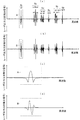
図2は、第1実施形態に係るレーザ周波数安定化装置により共振器長を変化させて、発振周波数を走査したときに得られる光出力信号S1の2次微分信号S2及び3次微分信号S3の波形の一例を示す図である。ここで、図2(a)は、2次微分信号S2の波形、図2(b)は、3次微分信号S3の波形を示す図である。また、図2(c)は、2次微分信号S2の領域Aを拡大した波形図、図2(d)は、3次微分信号S3の領域Bを拡大した波形図である。図2(a)に示すように、2次微分信号には、飽和吸収線が束になった飽和吸収線群が6群(符号N1〜N6)みられ、それぞれの飽和吸収線の本数及びその組み合わせは、低い発振周波数から順に1本(符号a1)、4本(符号a2〜a5)、4本(符号a6〜a9)、1本(符号a10)、4本(符号a11〜a14)、1本(符号a15)となっている。また、図2(b)に示すように3次微分信号においても、2次微分信号と略同様の特徴を有する信号が観測される。 FIG. 2 shows the second derivative signal S2 and the third derivative signal S3 of the optical output signal S1 obtained when the oscillation frequency is scanned by changing the resonator length by the laser frequency stabilizer according to the first embodiment. It is a figure which shows an example of a waveform. Here, FIG. 2A shows the waveform of the secondary differential signal S2, and FIG. 2B shows the waveform of the tertiary differential signal S3. FIG. 2C is a waveform diagram in which the region A of the secondary differential signal S2 is enlarged, and FIG. 2D is a waveform diagram in which the region B of the tertiary differential signal S3 is enlarged. As shown in FIG. 2A, in the secondary differential signal, there are 6 groups (symbols N 1 to N 6 ) of saturated absorption lines in which saturated absorption lines are bundled, and the number of each saturated absorption line. And the combination is one (symbol a 1 ), four (symbol a 2 to a 5 ), four (symbol a 6 to a 9 ), one (symbol a 10 ), four in order from the lowest oscillation frequency. (sign a 11 ~a 14), has a single (reference numeral a 15). As shown in FIG. 2B, a signal having substantially the same characteristics as the secondary differential signal is also observed in the tertiary differential signal.
図3は、アクチュエータ124をフルストローク動作(可動範囲全域に動作)させた時の2次微分信号S2、及びその2次微分信号S2の拡大図を示している。
FIG. 3 shows an enlarged view of the secondary differential signal S2 and the secondary differential signal S2 when the
ここで、共振器長Lとレーザ波長λの関係を以下に示す。 Here, the relationship between the resonator length L and the laser wavelength λ is shown below.

本発明の第1実施形態に係るレーザ周波数安定化装置は、これら飽和吸収線群(符号N1〜N6)、飽和吸収線(符号a1〜a15)、及びモードホップCを用いて、発振周波数を安定化させるものである。 The laser frequency stabilization device according to the first embodiment of the present invention uses these saturated absorption line groups (reference numerals N 1 to N 6 ), saturated absorption lines (reference signs a 1 to a 15 ), and mode hops C, It stabilizes the oscillation frequency.
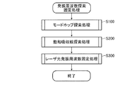
以下、図3〜図9を参照して、飽和吸収線を探索して、当該飽和吸収線にレーザ光L3の発振周波数を固定する処理を説明する。図4に示すように、先ず、自動ロック部36aは、モードホップCを探索し、当該モードホップCの周波数にレーザ光L8の発振周波数が重なるように、アクチュエータ制御部31からの出力電圧S4を制御する(ステップS100)。次に、自動ロック部36aは、出力電圧S4を制御し、2次微分信号S2に基づき、飽和吸収線を探索する(ステップS200)。そして、自動ロック部36aは、探索した飽和吸収線の中から、所望の飽和吸収線にレーザ光L8の発振周波数を固定する(ステップS300)。以下において、ステップS100の処理をモードホップ探索処理、ステップS200の処理を飽和吸収線探索処理、ステップS300の処理をレーザ光発振周波数固定処理と呼ぶ。
Hereinafter, a process for searching for a saturated absorption line and fixing the oscillation frequency of the laser beam L3 to the saturated absorption line will be described with reference to FIGS. As shown in FIG. 4, first, the
次に、上記ステップS100の処理(モードホップ探索処理)について、図5を参照して、詳細に説明する。図5に示すように、まず、自動ロック部36aは、アクチュエータ駆動部33からの出力電圧S5がアクチュエータ124の中心電圧となるように、出力電圧S4を増減させる(ステップS101)。なお、アクチュエータ124の中心電圧とは、アクチュエータ124を全駆動範囲の中心の状態とさせる電圧である。
Next, the process in step S100 (mode hop search process) will be described in detail with reference to FIG. As shown in FIG. 5, first, the
次に、自動ロック部36aは、出力電圧S4を所定値減少させる(ステップS102)。つづいて、自動ロック部36aは、出力電圧S4が、最小値になっているか否かを判断する(ステップS103)。ここで、自動ロック部36aが、出力電圧S4は最小値であると判断すると(ステップS103,Y)、後述するエラー検出処理が実行される(ステップS400)。一方、自動ロック部36aは、出力電圧S4が、最小値でないと判断すると(ステップS103,N)、2次微分信号S2及び3次微分信号S3の電圧を監視し、その電圧がモードホップ閾値V1以上であるか否かを判断する(ステップS104)。
Next, the
ここで、自動ロック部36aは、2次微分信号S2或いは3次微分信号S3の電圧がモードホップ閾値V1未満であると判断すると(ステップS104,N)、再度ステップS102からの処理を実行し、出力電圧S4を減少させる。一方、自動ロック部36aは、2次微分信号S2或いは3次微分信号S3の電圧がモードホップ閾値V1以上であると判断すると(ステップS104,Y)、上記処理を終了する。
When the
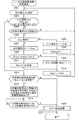
次に、図6を参照して、上記ステップS200の処理(飽和吸収線探索処理)について詳細に説明する。まず、自動ロック部36aは、出力電圧S4を増加させる(ステップS201)。次に、自動ロック部36aは、予め設定された所定条件の飽和吸収線を探索したか否かを判断する(ステップS202)。ここで、自動ロック部36aは、所定条件の飽和吸収線を探索したと判断すると(ステップS202,Y)、本フローを終了する。
Next, with reference to FIG. 6, the process of step S200 (saturated absorption line search process) will be described in detail. First, the
一方、自動ロック部36aが、所定条件の飽和吸収線を探索していないと判断すると(ステップS202,N)、次の処理に移行する。つづいて、自動ロック部36aは、出力電圧S4が最大値であるか否かを判断する(ステップS203)。ここで、自動ロック部36aは、出力電圧S4が、最大値であると判断すると(ステップS203,Y)、後述するエラー検出処理を実行する(ステップS400)。
On the other hand, when the
一方、自動ロック部36aは、出力電圧S4が、最大値でないと判断すると(ステップS203,N)、つづいて、2次微分信号S2の電圧が閾値V2以上であるか否かを判断する(ステップS204)。つまり、自動ロック部36aは、ステップS204にて、飽和吸収線と認定するか否かの判断を行う。ここで、自動ロック部36aは、2次微分信号S2の電圧が閾値V2未満であると判断すると(ステップS204,N)、再び、ステップ201からの処理を実行し、出力電圧S4を増加させる。
On the other hand, when the
一方、自動ロック部36aは、2次微分信号S2の電圧が閾値V2以上であると判断すると(ステップS204,Y)、つづいて、メモリ36bに後述するVoldが格納されているか否かを判断する(ステップS205)。
On the other hand, when the
ここで、自動ロック部36aが、メモリ36bにVoldが格納されていないと判断すると(ステップS205,N)、その出力電圧S4をVoldとしてメモリ36bに格納する(ステップS206)。続いて、自動ロック部36aは、その電圧Voldに関連づけて”N(N1)=1”との情報を格納する(ステップS207)。なお、ここで”N(N1)=1”の表記において、”N1”は、アクチュエータ制御部31の低出力電圧側から電圧を上げ、一番目に観測される飽和吸収線群であることを示し、”N(N1)=1”は、その飽和吸収線群に含まれる飽和吸収線の数を示す。続いて、自動ロック部36aは、ステップ201からの処理を繰り返し実行する。
If the
一方、ステップS205において、自動ロック部36aが、メモリ36bにVoldが格納されていると判断すると(ステップS205,Y)、その出力電圧S4をVnewとしてメモリ36bに格納する(ステップS208)。つづいて、自動ロック部36aは、以下に示す(式2)の関係が満たされるか否かを判断する(ステップS209)。
On the other hand, when the
![]()
![]()
![]()
![]()
続いて、自動ロック部36aは、VnewをVoldに変更し(ステップS211)、再びステップS201からの処理を実行する。
Subsequently, the
一方、自動ロック部36aは、上記(式2)が満たされていないと判断すると(ステップS209,N)、kに1を加算し、N(Nk)を1とする(ステップS212)。例えば、N(N2)=4であれば、N(N3)=1とする。換言すると、認定した飽和吸収線を新しい飽和吸収線群に含まれるものとする。続いて、自動ロック部36aは、上述したステップS211の処理を実行する。そして、上述したように、自動ロック部36aは、出力電圧S4を増加させ、所定条件の飽和吸収線の探索を終了したと判断すると(ステップS202,Y)、本フローを終了する。なお、上記処理を換言すると、自動ロック部36aは、ステップS205〜S212において、飽和吸収線群(飽和吸収線の組み合わせ)の認定を行っている。
On the other hand, when the
次に、図7を参照して、上記ステップS300の処理(レーザ光発振周波数固定処理)について詳細に説明する。まず、自動ロック部36aは、出力電圧S4を減少させる(ステップS301)。次に、自動ロック部36aは、Vold’がメモリ36bに格納されており、k=k2であり、且つVold’−出力電圧S4>ΔVの条件を満たすか否かを判断する(ステップS302)。ここで、自動ロック部36aは、ステップS302における条件を満たさないと判断した場合(ステップS302、N)、2次微分信号S2が閾値V2以上であるか否かを判断する(ステップS303)。ここで、自動ロック部36aは、2次微分信号S2が閾値V2未満であると判断すると(ステップS303,N)、再びステップS301から処理を繰り返し実行する。
Next, with reference to FIG. 7, the process (laser light oscillation frequency fixing process) in step S300 will be described in detail. First, the
一方、自動ロック部36aは、2次微分信号S2が閾値V2以上であると判断すると(ステップS303,Y)、Vold’がメモリ36bに格納されているか否かを判断する(ステップS304)。ここで、自動ロック部36aは、メモリ36bにVold’が格納されていないと判断すると(ステップS304,N)、出力電圧S4をVold’としてメモリ36bに格納する(ステップS305)。つづいて、自動ロック部36aは、飽和吸収線探索処理(ステップS200)にて得られたアクチュエータ制御部31の最も高い出力電圧側の飽和吸収線群Nkmaxの飽和吸収線数N(Nkmax)を1として(ステップS306)、再びステップS301からの処理を繰り返し実行する。
On the other hand, when the
一方、自動ロック部36aは、メモリ36bにVold’が格納されていると判断すると(ステップS303,Y)、出力電圧S4をVnew’としてメモリ36bに格納する(ステップS307)。
On the other hand, when determining that Vold 'is stored in the
つづいて、自動ロック部36aは、以下に示す(式4)の関係が満たされるか否かを判断する(ステップS308)。
Subsequently, the
一方、自動ロック部36aは、上記(式3)の関係を満たしている場合(ステップS308、Y)、N(Nk)に1を加算し(ステップ311)、上述したステップS310の処理を実行する。
On the other hand, if the relationship of (Expression 3) is satisfied (step S308, Y), the
一方、自動ロック部36aは、上述したステップS302において、Vold’が格納されており、k=k2であり、且つVold’−出力電圧S4>ΔVの条件を満たすと判断した場合(ステップS302、Y)、飽和吸収線探索処理(ステップS200)において探索した所定数の飽和吸収線群(Nmax〜Nk2)を再び探索したか否かを判断する(ステップS312)。なお、符号Nk2は、希望する飽和吸収線に応じた定数である。ここで、自動ロック部36aは、所定数の飽和吸収線群を探索したと判断すると(ステップS312,Y)、2次微分信号S2が閾値V2を所定回数超えるまで、出力電圧S4を増加、或いは減少させる(ステップS313)。すなわち、ステップS313において、レーザ光L8の発振周波数は、所望の飽和吸収線にロックされる。
On the other hand, when the
この飽和吸収線のロックに際して、例えば、メモリ36bには、図8に示すような各種パラメータが格納されている。図8に示す例であれば、ロックする飽和吸収線の名称(a1〜a15)、k2の値(2〜6)、ステップS313における出力電圧S4の増減方向(減少或いは増加)、ステップS313における2次微分信号S2の閾値V2を越える所定回数(1或いは2)が、パラメータとして格納されている。なお、図8に示すパラメータ以外でも、希望する飽和吸収線を探索し、ロックできれば、パラメータはどのように設定してもよい。例えば、飽和吸収線a7にロックする場合、k2を4、増減方向を減少、所定回数を3としてもよい。
When locking the saturated absorption line, for example, various parameters as shown in FIG. 8 are stored in the
ロック動作(ステップS313)後、自動ロック部36aは、2次微分信号S2と3次微分信号S3とを観測し、2次微分信号S2が閾値電圧V2未満であるか否か、または、3次微分信号S3が零近傍からずれているか否かを判断する(ステップS314)。ここで、自動ロック部36aは、2次微分信号S2が閾値電圧V2未満、または、3次微分信号S3が零近傍からずれていると判断すると(ステップS314,Y)、ロックが外れたとしてエラーメッセージ等を出力し、エラー検出処理を実行する(ステップS400)。また、自動ロック部36aは、ステップS312において、所定数の飽和吸収線を探索していないと判断すると(ステップS312,N)、エラー検出処理を実行する(ステップS400)。なお、上記処理を換言すると、自動ロック部36aは、ステップS301〜S313において、選定した飽和吸収線の特定を行っている。
After the locking operation (step S313), the
次に、図9を参照して、上記エラー検出処理を実行するステップ400について詳細に説明する。図9に示すように、先ず、自動ロック部36aは、エラー回数Errに1を加算する(ステップS401)。次に、自動ロック部36aは、加算したエラー回数Errが、エラー回数の閾値TErr以上であるか否かを判断する(ステップS402)。ここで、自動ロック部36aは、エラー回数Errが、閾値TErr未満であると判断すると(ステップS402,N)、モードホップ探索処理(ステップS100)を実行する。一方、自動ロック部36aは、エラー回数Errが、閾値TErr以上であると判断すると(ステップS402,Y)、レーザ光L8の異常であるとして、エラー検出処理を終了し、飽和吸収線探索処理(ステップS200)及びレーザ光発振周波数固定処理(ステップS300)を終了する。
Next, step 400 for executing the error detection process will be described in detail with reference to FIG. As shown in FIG. 9, first, the
以上のように本発明の第1実施形態に係るレーザ周波数安定化装置によれば、 飽和吸収線の本数を識別可能な測定精度であればよいので、容易に実現可能であると共に安価に製造可能である。また、このような構成により、経時変化の大きなアクチュエータを用いても、その経時変化に十分に追従して発振周波数を固定することが可能である。 As described above, according to the laser frequency stabilization device of the first embodiment of the present invention, any measurement accuracy that can identify the number of saturated absorption lines is sufficient, so that it can be easily realized and can be manufactured at low cost. It is. Further, with such a configuration, even if an actuator having a large change with time is used, the oscillation frequency can be fixed sufficiently following the change with time.
また、上述したように本発明の第1実施形態に係るレーザ周波数安定化装置は、飽和吸収線探索処理(ステップS200)にて、一度、飽和吸収線を測定し、レーザ光発振周波数固定処理(ステップS300)にて、再度飽和吸収線を測定して、発振周波数をロックする。つまり、レーザ周波数安定化装置は、再度測定することにより、間違いなくユーザの所望とする飽和吸収線にレーザ光の発振周波数をロックすることができ、さらには、その発振周波数の精度を向上させることができる。 Further, as described above, the laser frequency stabilizing device according to the first embodiment of the present invention measures the saturated absorption line once in the saturated absorption line search process (step S200), and performs the laser light oscillation frequency fixing process ( In step S300), the saturated absorption line is measured again to lock the oscillation frequency. In other words, the laser frequency stabilization device can definitely lock the oscillation frequency of the laser beam to the saturated absorption line desired by the user by measuring again, and further improve the accuracy of the oscillation frequency. Can do.
なお、上記第1実施形態においては、各飽和吸収線群の飽和吸収線の数、及びその組み合わせから飽和吸収線の特定を行っているが、単に、全体の飽和吸収線の数(例えば、図3においては、15本)から所望とする飽和吸収線を特定する構成であってもよい。 In the first embodiment, the saturated absorption lines are identified from the number of saturated absorption lines of each saturated absorption line group and the combination thereof. 3 may be configured to specify a desired saturated absorption line from 15).
また、図3において、飽和吸収線a3と飽和吸収線a4、飽和吸収線a11と飽和吸収線a12、飽和吸収線a13と飽和吸収線a14はそれぞれ発生する周波数が略等しい為、本来2本ある飽和吸収線が1本しか検出できない場合がある。この場合に備えて、飽和吸収線群の判断基準をN(N1)=1、3≦N(N2)≦4、N(N3)=4、N(N4)=1、2≦N(N5)≦4、かつ、N(N6)=1としてもよい。 Further, in FIG. 3, the saturated absorption line a3 and the saturated absorption line a4, the saturated absorption line a11 and the saturated absorption line a12, and the saturated absorption line a13 and the saturated absorption line a14 are generated at substantially the same frequency. In some cases, only one absorption line can be detected. In preparation for this case, the criteria for determining the saturated absorption line group are N (N 1 ) = 1, 3 ≦ N (N 2 ) ≦ 4, N (N 3 ) = 4, N (N 4 ) = 1, 2 ≦ N (N 5 ) ≦ 4 and N (N 6 ) = 1 may be set.
また、自動ロック部36aは、飽和吸収線の認定を2次微分信号から行っているが、これは3次微分信号から検出することも可能である。
Moreover, although the automatic lock |
[第2実施形態]
次に、本発明の第2実施形態に係るレーザ周波数安定化装置の構成を説明する。
第2実施形態に係るレーザ周波数安定化装置は、図1に示す第1実施形態と略同様の構成を有する。第2実施形態に係るレーザ周波数安定化装置においては、アクチュエータ制御部31、及びアクチュエータ駆動部33によるアクチュエータ124の駆動可能な範囲が第1実施形態と異なる。また、コンピュータ36(自動ロック部36a)の機能が第1実施形態と異なる。また、共振器に設けられた希望の周波数を選択するための周波数フィルタが第1実施形態と異なる。なお、以下の第2実施形態の説明において、第1実施形態と同一の構成及び処理には、同一符号を付し、その説明を省略する。
[Second Embodiment]
Next, the configuration of the laser frequency stabilization device according to the second embodiment of the present invention will be described.
The laser frequency stabilizing device according to the second embodiment has substantially the same configuration as that of the first embodiment shown in FIG. In the laser frequency stabilizing device according to the second embodiment, the range in which the
まず、図10を参照して、第2実施形態に係るレーザ周波数安定化装置の制御時に検出する2次微分信号及び光出力信号を説明する。ここで、図10は、本発明の第2実施形態に係るレーザ周波数安定化装置の制御時に検出する2次微分信号及び光出力信号を示す図である。図10(a)は、2次微分信号及び光出力信号を示し、図10(b)は、図10(a)の領域Dを拡大した2次微分信号を示す図である。 First, with reference to FIG. 10, the secondary differential signal and the optical output signal detected during the control of the laser frequency stabilizer according to the second embodiment will be described. Here, FIG. 10 is a diagram showing a second-order differential signal and an optical output signal detected during control of the laser frequency stabilizer according to the second embodiment of the present invention. 10A shows the secondary differential signal and the optical output signal, and FIG. 10B shows the secondary differential signal obtained by enlarging the region D of FIG. 10A.
図10(a)に示すように、第2実施形態に係るレーザ周波数安定化装置は、第1実施形態(図3)と比較して、レーザ光を幅広い出力電圧S4により制御可能である。このように、幅広く出力電圧S4を走査すると、周期的に繰り返して、光出力信号S1の吸収線の観測される電圧に、飽和吸収線群(飽和吸収線)が束となって観測されることがわかる。すなわち、図10に示す走査範囲内にて、4つの吸収線M1〜M4に属する飽和吸収線が観測されている。ここで、吸収線M1と吸収線M3は、同一の吸収線であり、吸収線M2と吸収線M4は、同一の吸収線である。 As shown in FIG. 10A, the laser frequency stabilizing device according to the second embodiment can control the laser beam with a wider output voltage S4 than in the first embodiment (FIG. 3). As described above, when the output voltage S4 is scanned widely, the saturated absorption line group (saturated absorption line) is observed as a bundle in the voltage observed on the absorption line of the optical output signal S1 periodically and repeatedly. I understand. That is, saturated absorption lines belonging to the four absorption lines M 1 to M 4 are observed within the scanning range shown in FIG. Here, the absorption line M 1 and the absorption line M 3 are, the same absorption line, the absorption line M 2 absorption line M 4 is the same absorption line.
また、図10(a)に示すように、モードホップEが観測されている。この第2実施形態において、モードホップEは、第1実施形態よりもその変動幅が小さい。つまり、飽和吸収線よりもその変動幅が小さいので、第1実施形態のように、モードホップ閾値V1を設けてモードホップEを特定することはできない。そこで、第2実施形態においては、モードホップEを検索することなく、レーザ光の発振周波数を固定する処理を行う構成となっている。なお、モードホップEの変動幅及びその形状は、第2実施形態の共振器内に設けた第1実施形態と異なる周波数フィルタの影響を受けている。 Further, as shown in FIG. 10A, a mode hop E is observed. In the second embodiment, the mode hop E has a smaller fluctuation range than the first embodiment. That is, since the fluctuation range is smaller than that of the saturated absorption line, the mode hop E cannot be specified by providing the mode hop threshold V1 as in the first embodiment. Therefore, the second embodiment is configured to perform processing for fixing the oscillation frequency of the laser light without searching for the mode hop E. Note that the fluctuation range and the shape of the mode hop E are affected by a frequency filter different from that of the first embodiment provided in the resonator of the second embodiment.
次に、図11を参照して、第2実施形態に係るレーザ周波数安定化装置による発振周波数を固定する制御について説明する。図11は、第2実施形態に係るレーザ周波数安定化装置の発振周波数探索固定処理を示すフローチャートである。図11に示すように、先ず、自動ロック部36aは、飽和吸収線を探索する飽和吸収線探索処理を行う(ステップS500)。その後、自動ロック部36aは、第1実施形態と同様のレーザ光発振周波数固定処理(ステップS300)を実行する。
Next, control for fixing the oscillation frequency by the laser frequency stabilizing device according to the second embodiment will be described with reference to FIG. FIG. 11 is a flowchart showing an oscillation frequency search / fixing process of the laser frequency stabilizer according to the second embodiment. As shown in FIG. 11, first, the
次に、図12及び図13を参照して、第2実施形態における飽和吸収線探索処理(ステップS500)を説明する。図12に示すように、まず、自動ロック部36aは、アクチュエータ駆動部33からの出力電圧S5がアクチュエータ124の最大電圧となるように、出力電圧S4を増加させる(ステップS501)。なお、アクチュエータ124の最大電圧とは、アクチュエータ124を駆動範囲の最大の状態とさせる電圧である。つづいて、自動ロック部36aは、出力電圧S4を減少させる(ステップS502)。そして、自動ロック部36aは、メモリ36bにVold’’が格納されており、Vold’’−出力電圧S4>ΔV’、且つN(Mk)=iの条件を満たすか否かを判断する(ステップS503)。ここで”N(Mk)=i”の表記において、”Mk”は、アクチュエータ制御部31の高出力電圧側から電圧を下げ、k番目に観測される吸収線に属する飽和吸収線であることを示し、”N(Mk)=i”は、その吸収線に属する飽和吸収線がi本存在することを示す。
Next, the saturated absorption line search process (step S500) in the second embodiment will be described with reference to FIGS. As shown in FIG. 12, first, the
ステップS503において、自動ロック部36aは、ステップS503の条件を満たすと判断する場合(ステップS503、Y)、出力電圧S4をVgとしてメモリ36bに格納する(ステップS504)。続いて、自動ロック部36aは、出力電圧S4が最小値であるか否かを判断する(ステップS505)。なお、自動ロック部36aは、上記ステップS503において、条件を満たさないと判断した場合(ステップS503、N)、ステップS504を省略し、ステップS505の判断を行う。
In step S503, when the
ここで、自動ロック部36aは、出力電圧S4が最小値でないと判断すると(ステップS505,N)、2次微分信号S2が閾値V2以上であるか否かを判断する(ステップS506)。ここで、自動ロック部36aは、2次微分信号S2が閾値V2未満であると判断すると(ステップS506,N)、再びステップS502からの処理を繰り返し実行する。
When the
一方、自動ロック部36aは、2次微分信号S2が閾値V2以上であると判断すると(ステップS506,Y)、メモリ36bに後述するVold’’が格納されているか否かを判断する(ステップS507)。ここで、自動ロック部36aは、Vold’’がメモリ36bに格納されていないと判断すると(ステップS507,N)、出力電圧S4をVold’’として格納する(ステップS508)。続いて、自動ロック部36aは、その電圧Vold’’に関連づけて”N(M1)=1”との情報を格納する(ステップS509)。続いて、自動ロック部36aは、ステップS502からの処理を繰り返して実行する。
On the other hand, when the
一方、ステップS507にて、自動ロック部36aは、Vold’’がメモリ36bに格納されていると判断すると(ステップS507,Y)、出力電圧S4をVnew’’としてメモリ36bに格納する(ステップS510)。つづいて、自動ロック部36aは、以下に示す(式5)の関係が満たされるか否かを判断する(ステップS511)。
On the other hand, in step S507, when the
![]()
![]()
![]()
![]()
一方、自動ロック部36aは、上記(式6)が満たされていないと判断すると(ステップS511,N)、kに1を加算し、N(Mk)を1とする(ステップS513)。例えば、N(M2)=4であれば、N(M3)=1とする。換言すると、認定した飽和吸収線を異なる吸収線に含まれるものとする。ステップS512或いはステップS513に続き、自動ロック部36aは、Vnew’’をVold’’とし(ステップS514)、ステップS502からの処理を繰り返して実行する。
On the other hand, when the
また、自動ロック部36aは、ステップS505において、出力電圧S4が最小電圧であると判断すると(ステップS503,Y)、メモリ36bにVgが格納されているか否かを判断する(ステップS515)。ここで、自動ロック部36aは、メモリ36bにVgが格納されていると判断すると(ステップS515,Y)、出力電圧S5がアクチュエータ124の中心電圧近傍のVgになるように出力電圧S4を増加させる(ステップS516)。例えば、図10(a)に示す例においては、15本の飽和吸収線を有する吸収線に対象に設定している場合、2つの同一の吸収線M2と吸収線M4が観測されるが、アクチュエータ124の中心電圧近傍である吸収線M2のVgに合わせるように出力電圧S4を増加させる。
Further, when the
つづいて、自動ロック部36aは、図13に示すステップS517〜S528の処理を実行する。なお、ステップS517〜S528の処理は、第1実施形態における飽和吸収線探索処理(ステップS200)のステップS201〜S212の処理と同様であるため、その説明を省略する。
Subsequently, the
一方、自動ロック部36aは、メモリ36bにVgが格納されていないと判断すると(ステップS515,N)、第1実施形態と同様のエラー検出処理を実行する(ステップS400)。
On the other hand, when the
つまり、第2実施形態における飽和吸収線探索処理において、ステップS501〜S516にて飽和吸収線間の出力電圧S4を閾値V’で判断することにより飽和吸収線の属する吸収線を判断する。また、ステップS517〜ステップS530にて飽和吸収線間の出力電圧S4を閾値Vで判断することにより飽和吸収線の含まれる飽和吸収線群を判断する。 That is, in the saturated absorption line search process in the second embodiment, the absorption line to which the saturated absorption line belongs is determined by determining the output voltage S4 between the saturated absorption lines based on the threshold value V ′ in steps S501 to S516. In step S517 to step S530, the saturated absorption line group including the saturated absorption line is determined by determining the output voltage S4 between the saturated absorption lines with the threshold value V.
以上のように、第2実施形態に係るレーザ周波数安定化装置によれば、第1実施形態と同様の効果を得ることができる。また、第2実施形態に係るレーザ周波数安定化装置によれば、装置の個体差によるモードホップの波形の違いを考慮しなくとも良い。また、共振器長の全領域内で、希望する飽和吸収線が複数存在する場合、よりアクチュエータの中心電圧に近い飽和吸収線を選択するため、温度変化に対してよりロバストになる。つまり、共振器長の可動範囲の狭い飽和吸収線を選択してしまい、ロックが外れてしまう等の恐れはない。 As described above, according to the laser frequency stabilization device of the second embodiment, the same effect as that of the first embodiment can be obtained. In addition, according to the laser frequency stabilizing device according to the second embodiment, it is not necessary to consider the difference in mode hop waveform due to individual differences between devices. Further, when there are a plurality of desired saturated absorption lines in the entire region of the resonator length, a saturated absorption line closer to the center voltage of the actuator is selected, so that it is more robust to temperature changes. That is, there is no fear that the saturated absorption line having a narrow movable range of the resonator length is selected and the lock is released.
1…レーザ発生部、10…励起用半導体レーザ、11…集光系、12…共振波生成部、121a…Nd:YVO4結晶、121b…Nd:YVO4結晶ホルダ、122a…KTP結晶(非線形光学結晶)、122b…KTP結晶ホルダ(非線形光学結晶格納部)、123…反射鏡、124…アクチュエータ、125…レーザ共振器筐体、2…レーザ光検出部、21…高調波分離器、22a…λ/2板、22b…λ/4板、23a、23b…偏光ビームスプリッタ、24…ヨウ素セル、25…反射板、26…光検出装置、3…駆動制御部、31…アクチュエータ制御部、32…変復調用信号発生部、33…アクチュエータ駆動部、34…2次微分用ロックインアンプ、35…3次微分用ロックインアンプ、36…コンピュータ、36a…自動ロック部、36b…メモリ。
DESCRIPTION OF
Claims (8)
前記共振器に設けられた所定の周波数を選択する周波数フィルタと、
前記光出力信号を検出する光検出部と、
前記共振器長を変化させるアクチュエータと、
前記アクチュエータを駆動させる駆動部と、
前記駆動部によって前記アクチュエータを駆動して前記共振器長を変化させて発振周波数を走査したときに得られる前記光出力信号の微分信号を検出する微分信号検出部と、
前記微分信号に基づき前記駆動部を制御する制御部とを備え、
前記制御部は、前記共振器長が最大及び最小のいずれか一方から他方に変化するように前記駆動部を制御して、周期的に繰り返す複数の飽和吸収線からなる複数の飽和吸収線群を検出し、前記複数の飽和吸収線群の一つを選択して、前記選択された飽和吸収線群の中の特定の飽和吸収線を前記選択された飽和吸収線群の発振周波数軸に沿って現れる飽和吸収線の本数により選定し、該選定した特定の飽和吸収線に前記レーザ光の発振周波数を固定する
ことを特徴とするレーザ周波数安定化装置。 Based on a saturated absorption line included in an optical output signal obtained by resonating excitation light with a resonator comprising a pair of mirrors at opposite positions to generate laser light and irradiating the absorption light to the absorption cell. A laser frequency stabilizing device that changes the resonator length to fix and stabilize the oscillation frequency of the laser beam,
A frequency filter for selecting a predetermined frequency provided in the resonator;
A light detector for detecting the light output signal ;
An actuator for changing the pre-Symbol cavity length,
A drive unit for driving the actuator;
A differential signal detection unit that detects a differential signal of the optical output signal obtained by driving the actuator by the drive unit and changing the resonator length to scan the oscillation frequency ;
A control unit for controlling the drive unit based on the differential signal,
The control unit controls the driving unit so that the resonator length changes from one of the maximum and the minimum to the other, and includes a plurality of saturated absorption lines that are periodically repeated. Detecting and selecting one of the plurality of saturated absorption line groups, and selecting a specific saturated absorption line in the selected saturated absorption line group along the oscillation frequency axis of the selected saturated absorption line group A laser frequency stabilizing device, characterized in that the laser frequency is selected based on the number of saturated absorption lines that appear , and the oscillation frequency of the laser light is fixed to the selected specific saturated absorption line.
ことを特徴とする請求項1記載のレーザ周波数安定化装置。 The control unit is identified as interval saturated absorption line driver control voltage obtained the saturated absorption lines for adjacent said adjacent saturated absorption lines, if a predetermined threshold is included in the same saturated absorption line group The laser frequency stabilizing device according to claim 1, wherein:
ことを特徴とする請求項1又は2記載のレーザ周波数安定化装置。 The said control part selects the saturated absorption line group which appears in the said drive control voltage close | similar to the center voltage of the maximum value of the said drive control voltage, and the minimum value among these saturated absorption line groups. 3. The laser frequency stabilizing device according to 1 or 2.
前記共振器に所定の周波数を選択する周波数フィルタを設け、
前記共振器長が最大及び最小のいずれか一方から他方に変化するようにして、周期的に繰り返す複数の飽和吸収線からなる複数の飽和吸収線群を検出し、前記複数の飽和吸収線群の一つを選択し、前記選択された飽和吸収線群の中の特定の飽和吸収線を前記選択された飽和吸収線群の発振周波数軸に沿って現れる飽和吸収線の本数により選定する飽和吸収線選定ステップと、
該選定した特定の飽和吸収線に前記レーザ光の発振周波数を固定する発振周波数固定ステップと
を有することを特徴とするレーザ周波数安定化方法。 A laser beam is generated by resonating excitation light with a resonator having a pair of mirrors arranged at opposite positions, and the laser beam is irradiated to the absorption cell while scanning the oscillation frequency by changing the resonator length. A laser frequency stabilization method for changing the resonator length based on a saturated absorption line included in a differential signal of an optical output signal obtained by fixing the oscillation frequency of the laser light and stabilizing the laser beam,
A frequency filter for selecting a predetermined frequency is provided in the resonator,
A plurality of saturated absorption line groups consisting of a plurality of saturated absorption lines that are periodically repeated are detected such that the resonator length changes from one of the maximum and the minimum to the other. A saturated absorption line is selected by selecting one and selecting a specific saturated absorption line in the selected saturated absorption line group according to the number of saturated absorption lines appearing along the oscillation frequency axis of the selected saturated absorption line group. A selection step;
An oscillation frequency fixing step of fixing the oscillation frequency of the laser beam to the selected specific saturated absorption line.
前記共振器に所定の周波数を選択する周波数フィルタを設け、
コンピュータに、
前記共振器長が最大及び最小のいずれか一方から他方に変化するようにして、周期的に繰り返す複数の飽和吸収線からなる複数の飽和吸収線群を検出し、前記複数の飽和吸収線群の一つを選択し、前記選択された飽和吸収線群の中の特定の飽和吸収線を前記選択された飽和吸収線群の発振周波数軸に沿って現れる飽和吸収線の本数により選定する飽和吸収線選定ステップと、
該選定した特定の飽和吸収線に前記レーザ光の発振周波数を固定する発振周波数固定ステップと
を実行させるためのレーザ周波数安定化プログラム。 A laser beam is generated by resonating excitation light with a resonator having a pair of mirrors arranged at opposite positions, and the laser beam is irradiated to the absorption cell while scanning the oscillation frequency by changing the resonator length. A laser frequency stabilization program for stabilizing by changing the resonator length based on a saturated absorption line included in a differential signal of an optical output signal obtained in the above manner and fixing the oscillation frequency of the laser beam,
A frequency filter for selecting a predetermined frequency is provided in the resonator,
On the computer,
A plurality of saturated absorption line groups consisting of a plurality of saturated absorption lines that are periodically repeated are detected such that the resonator length changes from one of the maximum and the minimum to the other. A saturated absorption line is selected by selecting one and selecting a specific saturated absorption line in the selected saturated absorption line group according to the number of saturated absorption lines appearing along the oscillation frequency axis of the selected saturated absorption line group. A selection step;
A laser frequency stabilization program for executing the oscillation frequency fixing step of fixing the oscillation frequency of the laser light to the selected specific saturated absorption line.
Priority Applications (3)
| Application Number | Priority Date | Filing Date | Title |
|---|---|---|---|
| JP2006327218A JP4897449B2 (en) | 2006-12-04 | 2006-12-04 | Laser frequency stabilization device, laser frequency stabilization method, and laser frequency stabilization program |
| US11/987,507 US7613216B2 (en) | 2006-12-04 | 2007-11-30 | Laser frequency stabilizing apparatus, method and computer program product for stabilizing laser frequency |
| EP07122027.1A EP1930998B1 (en) | 2006-12-04 | 2007-11-30 | Laser frequency stabilizing apparatus, method and computer program product for stabilizing laser frequency |
Applications Claiming Priority (1)
| Application Number | Priority Date | Filing Date | Title |
|---|---|---|---|
| JP2006327218A JP4897449B2 (en) | 2006-12-04 | 2006-12-04 | Laser frequency stabilization device, laser frequency stabilization method, and laser frequency stabilization program |
Publications (2)
| Publication Number | Publication Date |
|---|---|
| JP2008141054A JP2008141054A (en) | 2008-06-19 |
| JP4897449B2 true JP4897449B2 (en) | 2012-03-14 |
Family
ID=39126213
Family Applications (1)
| Application Number | Title | Priority Date | Filing Date |
|---|---|---|---|
| JP2006327218A Active JP4897449B2 (en) | 2006-12-04 | 2006-12-04 | Laser frequency stabilization device, laser frequency stabilization method, and laser frequency stabilization program |
Country Status (3)
| Country | Link |
|---|---|
| US (1) | US7613216B2 (en) |
| EP (1) | EP1930998B1 (en) |
| JP (1) | JP4897449B2 (en) |
Families Citing this family (20)
| Publication number | Priority date | Publication date | Assignee | Title |
|---|---|---|---|---|
| JP5042781B2 (en) * | 2007-11-06 | 2012-10-03 | 株式会社ミツトヨ | Frequency stabilized laser device and laser frequency stabilizing method |
| JP2009218488A (en) * | 2008-03-12 | 2009-09-24 | Mitsutoyo Corp | Device, method and program for stabilizing laser frequency |
| JP5706680B2 (en) * | 2010-12-22 | 2015-04-22 | 株式会社ミツトヨ | Stabilization discriminator, laser frequency stabilization device, and stabilization discrimination method |
| JP5695426B2 (en) * | 2011-01-07 | 2015-04-08 | 株式会社ミツトヨ | Absolute distance measuring method for laser interferometer and laser interferometer |
| JP5763451B2 (en) * | 2011-07-05 | 2015-08-12 | 株式会社ミツトヨ | Saturated absorption line determination method and laser frequency stabilization device |
| JP5859793B2 (en) | 2011-09-28 | 2016-02-16 | 株式会社ミツトヨ | Optical output signal stabilization determination method and laser frequency stabilization device |
| JP2013152146A (en) | 2012-01-25 | 2013-08-08 | Techno Echo Kk | Water quality inspection device and water quality inspection method |
| JP6027316B2 (en) * | 2012-01-26 | 2016-11-16 | 株式会社ミツトヨ | Saturated absorption line determination method and laser frequency stabilization device |
| US9077354B2 (en) * | 2012-04-10 | 2015-07-07 | Honeywell International Inc. | Low power reduction of biases in a micro primary frequency standard |
| JP6154657B2 (en) * | 2013-05-02 | 2017-06-28 | 株式会社ミツトヨ | Laser equipment |
| US10925515B2 (en) | 2014-05-22 | 2021-02-23 | Picomole Inc. | Alveolar breath collection apparatus |
| JP6469472B2 (en) * | 2015-02-17 | 2019-02-13 | 株式会社ミツトヨ | Laser frequency stabilization device and laser frequency stabilization method |
| JP6934748B2 (en) * | 2016-06-14 | 2021-09-15 | 株式会社ミツトヨ | Laser device and frequency shift amount identification method |
| US10666012B2 (en) * | 2017-03-13 | 2020-05-26 | Picomole Inc. | Apparatus and method of optimizing laser system |
| JP2019087550A (en) | 2017-11-01 | 2019-06-06 | 株式会社ミツトヨ | Laser device and laser stabilization method |
| JP2019149400A (en) | 2018-02-26 | 2019-09-05 | 株式会社ミツトヨ | Laser light source device and laser light adjustment method |
| US11035789B2 (en) | 2019-04-03 | 2021-06-15 | Picomole Inc. | Cavity ring-down spectroscopy system and method of modulating a light beam therein |
| JP7376280B2 (en) | 2019-08-21 | 2023-11-08 | 株式会社ミツトヨ | Laser device and laser stabilization method |
| US11782049B2 (en) | 2020-02-28 | 2023-10-10 | Picomole Inc. | Apparatus and method for collecting a breath sample using a container with controllable volume |
| US11957450B2 (en) | 2020-02-28 | 2024-04-16 | Picomole Inc. | Apparatus and method for collecting a breath sample using an air circulation system |
Family Cites Families (10)
| Publication number | Priority date | Publication date | Assignee | Title |
|---|---|---|---|---|
| JP2761505B2 (en) * | 1990-09-26 | 1998-06-04 | 日本電信電話株式会社 | Wavelength stabilized laser device |
| JPH0786668A (en) * | 1993-09-10 | 1995-03-31 | Hitachi Metals Ltd | Semiconductor laser excited solid-state laser device |
| JPH10163549A (en) * | 1996-12-03 | 1998-06-19 | Nikon Corp | Laser light source device and support structure thereof |
| US6009111A (en) * | 1997-04-17 | 1999-12-28 | University Technology Corporation | System and a method for frequency-stabilizing a diode laser |
| US5978391A (en) * | 1997-07-18 | 1999-11-02 | Cymer, Inc. | Wavelength reference for excimer laser |
| JP3950570B2 (en) * | 1999-03-09 | 2007-08-01 | アンリツ株式会社 | Frequency stabilized light source |
| JP2001274483A (en) * | 2000-03-27 | 2001-10-05 | Neoark Corp | Modulation control method and calibration method for laser device |
| JP2001274495A (en) * | 2000-03-27 | 2001-10-05 | Neoark Corp | Autolock method for laser beam oscillation frequency |
| JP4389451B2 (en) * | 2003-02-24 | 2009-12-24 | オムロン株式会社 | Semiconductor laser pumped solid state laser device and operation method thereof |
| JP2007019361A (en) * | 2005-07-11 | 2007-01-25 | Mitsutoyo Corp | Frequency stabilization laser |
-
2006
- 2006-12-04 JP JP2006327218A patent/JP4897449B2/en active Active
-
2007
- 2007-11-30 EP EP07122027.1A patent/EP1930998B1/en active Active
- 2007-11-30 US US11/987,507 patent/US7613216B2/en active Active
Also Published As
| Publication number | Publication date |
|---|---|
| US20080130694A1 (en) | 2008-06-05 |
| US7613216B2 (en) | 2009-11-03 |
| EP1930998B1 (en) | 2017-07-05 |
| JP2008141054A (en) | 2008-06-19 |
| EP1930998A1 (en) | 2008-06-11 |
Similar Documents
| Publication | Publication Date | Title |
|---|---|---|
| JP4897449B2 (en) | Laser frequency stabilization device, laser frequency stabilization method, and laser frequency stabilization program | |
| JP2007019361A (en) | Frequency stabilization laser | |
| JP5042781B2 (en) | Frequency stabilized laser device and laser frequency stabilizing method | |
| US20070268568A1 (en) | Laser module and method of controlling wavelength of external cavity laser | |
| US10505336B2 (en) | Laser adjustment method and laser source device | |
| US7978737B2 (en) | Laser device, control device of laser device, method of controlling laser device, method of tuning wavelength of laser device and control data of laser device | |
| JP6469472B2 (en) | Laser frequency stabilization device and laser frequency stabilization method | |
| JP6250762B2 (en) | Optimization of the laser operating point of a laser absorption spectrometer. | |
| US7103075B2 (en) | Solid laser apparatus | |
| JP6027316B2 (en) | Saturated absorption line determination method and laser frequency stabilization device | |
| JP5324332B2 (en) | Optical frequency comb stabilized light source | |
| JP2008130848A (en) | Laser frequency stabilizing apparatus, and laser frequency stabilizing method | |
| JP5557601B2 (en) | Laser light source adjustment system | |
| US10630046B2 (en) | Laser light source device and laser light adjusting method | |
| JP2000208849A (en) | Semiconductor laser exciting solid-state laser device | |
| Teng | Frequency Control and Stabilization of a Laser System | |
| JP2017224806A (en) | Laser device and frequency shift amount specification method | |
| US20220102933A1 (en) | Laser apparatus | |
| Bhatia et al. | Precisely tunable, narrow-band pulsed dye laser | |
| Sturner | Development of a 780 nm External Cavity Diode Laser for Rubidium Spectroscopy | |
| JP2008058918A (en) | Terahertz electromagnetic wave generation method and spectroscopy/imaging measuring device | |
| JP2011515014A (en) | Frequency stabilized laser device and laser frequency stabilizing method | |
| JP2001267672A (en) | Laser device | |
| JP2011100812A (en) | Laser light source device, and adjustment system of laser light source | |
| JP2006032882A (en) | Solid-state laser apparatus |
Legal Events
| Date | Code | Title | Description |
|---|---|---|---|
| A621 | Written request for application examination |
Free format text: JAPANESE INTERMEDIATE CODE: A621 Effective date: 20091029 |
|
| A131 | Notification of reasons for refusal |
Free format text: JAPANESE INTERMEDIATE CODE: A131 Effective date: 20110830 |
|
| A977 | Report on retrieval |
Free format text: JAPANESE INTERMEDIATE CODE: A971007 Effective date: 20110831 |
|
| A521 | Written amendment |
Free format text: JAPANESE INTERMEDIATE CODE: A523 Effective date: 20111028 |
|
| TRDD | Decision of grant or rejection written | ||
| A01 | Written decision to grant a patent or to grant a registration (utility model) |
Free format text: JAPANESE INTERMEDIATE CODE: A01 Effective date: 20111206 |
|
| A01 | Written decision to grant a patent or to grant a registration (utility model) |
Free format text: JAPANESE INTERMEDIATE CODE: A01 |
|
| A61 | First payment of annual fees (during grant procedure) |
Free format text: JAPANESE INTERMEDIATE CODE: A61 Effective date: 20111222 |
|
| R150 | Certificate of patent or registration of utility model |
Ref document number: 4897449 Country of ref document: JP Free format text: JAPANESE INTERMEDIATE CODE: R150 Free format text: JAPANESE INTERMEDIATE CODE: R150 |
|
| FPAY | Renewal fee payment (event date is renewal date of database) |
Free format text: PAYMENT UNTIL: 20150106 Year of fee payment: 3 |
|
| R250 | Receipt of annual fees |
Free format text: JAPANESE INTERMEDIATE CODE: R250 |
|
| R250 | Receipt of annual fees |
Free format text: JAPANESE INTERMEDIATE CODE: R250 |
|
| R250 | Receipt of annual fees |
Free format text: JAPANESE INTERMEDIATE CODE: R250 |