JP4893747B2 - Wireless communication system - Google Patents
Wireless communication systemInfo
- Publication number
- JP4893747B2 JP4893747B2 JP2008542979A JP2008542979A JP4893747B2 JP 4893747 B2 JP4893747 B2 JP 4893747B2 JP 2008542979 A JP2008542979 A JP 2008542979A JP 2008542979 A JP2008542979 A JP 2008542979A JP 4893747 B2 JP4893747 B2 JP 4893747B2
- Authority
- JP
- Japan
- Prior art keywords
- frequency
- terminal
- unit
- information
- bandwidth
- Prior art date
- Legal status (The legal status is an assumption and is not a legal conclusion. Google has not performed a legal analysis and makes no representation as to the accuracy of the status listed.)
- Active
Links
Images


Classifications
-
- H—ELECTRICITY
- H04—ELECTRIC COMMUNICATION TECHNIQUE
- H04W—WIRELESS COMMUNICATION NETWORKS
- H04W8/00—Network data management
- H04W8/22—Processing or transfer of terminal data, e.g. status or physical capabilities
-
- H—ELECTRICITY
- H04—ELECTRIC COMMUNICATION TECHNIQUE
- H04W—WIRELESS COMMUNICATION NETWORKS
- H04W72/00—Local resource management
- H04W72/02—Selection of wireless resources by user or terminal
-
- H—ELECTRICITY
- H04—ELECTRIC COMMUNICATION TECHNIQUE
- H04W—WIRELESS COMMUNICATION NETWORKS
- H04W72/00—Local resource management
- H04W72/04—Wireless resource allocation
- H04W72/044—Wireless resource allocation based on the type of the allocated resource
- H04W72/0453—Resources in frequency domain, e.g. a carrier in FDMA
-
- H—ELECTRICITY
- H04—ELECTRIC COMMUNICATION TECHNIQUE
- H04W—WIRELESS COMMUNICATION NETWORKS
- H04W72/00—Local resource management
- H04W72/20—Control channels or signalling for resource management
-
- H—ELECTRICITY
- H04—ELECTRIC COMMUNICATION TECHNIQUE
- H04W—WIRELESS COMMUNICATION NETWORKS
- H04W72/00—Local resource management
- H04W72/50—Allocation or scheduling criteria for wireless resources
- H04W72/51—Allocation or scheduling criteria for wireless resources based on terminal or device properties
-
- H—ELECTRICITY
- H04—ELECTRIC COMMUNICATION TECHNIQUE
- H04W—WIRELESS COMMUNICATION NETWORKS
- H04W8/00—Network data management
- H04W8/22—Processing or transfer of terminal data, e.g. status or physical capabilities
- H04W8/24—Transfer of terminal data
Landscapes
- Engineering & Computer Science (AREA)
- Computer Networks & Wireless Communication (AREA)
- Signal Processing (AREA)
- Databases & Information Systems (AREA)
- Mobile Radio Communication Systems (AREA)
Description
本発明は、上りに使用する第1の周波数帯域幅及びその中心周波数、並びに下りに使用する第2の周波数帯域幅及びその中心周波数の両者または一方が可変である端末装置を用いた無線通信技術に関する。 The present invention relates to a radio communication technique using a terminal device in which both or one of the first frequency bandwidth and its center frequency used for uplink and the second frequency bandwidth and its center frequency used for downlink are variable. About.
近年、無線通信ではより高速な通信速度が要求されるようになっており、例えば携帯電話等の移動通信サービスでは、高速化の要求により、高速広帯域通信方式の検討が進められている。その一つの通信方式としてW−CDMA(Wideband-Code Division Multiple Access)方式が、3GPP(3rd Generation Partnership Project)において、検討され標準化が進められている。 In recent years, higher communication speeds have been required for wireless communication. For example, in mobile communication services such as mobile phones, high-speed broadband communication systems have been studied in response to demands for higher speeds. As one of the communication systems, a W-CDMA (Wideband-Code Division Multiple Access) system has been studied and standardized in 3GPP (3rd Generation Partnership Project).
以下、W−CDMA方式を例として説明する。W−CDMAシステムでは、携帯電話機や自動車電話機などの端末装置(UE:User Equipment)と、端末装置(以後「端末」と略す)と通信を行う基地局(Node B)及び複数の無線基地局(以後「基地局」と略す)を制御する無線制御装置(RNC:Radio Network Controller)で構成される(図5)。 Hereinafter, the W-CDMA system will be described as an example. In the W-CDMA system, a terminal device (UE: User Equipment) such as a mobile phone or a car phone, a base station (Node B) that communicates with a terminal device (hereinafter abbreviated as “terminal”), and a plurality of radio base stations ( It is comprised by the radio | wireless control apparatus (RNC: Radio Network Controller) which controls (it abbreviates a "base station" hereafter) (FIG. 5).
上記W−CDMA方式では、FDD(Frequency Division Duplex)またはTDD(Time Division Duplex)を用いより高速な通信速度を広帯域化によって実現させており、FDDモードでは上り/下りリンクに独立の周波数資源を割り当てている。上りリンク(uplink)に使用可能な周波数帯域(上り周波数帯域)、及び下りリンク(downlink)に使用可能な周波数帯域(下り周波数帯域)は法令(電波法等)によって規定されている。例えば、日本においてサービスが提供されている2GHz帯の場合、それらの帯域幅は共に5.0MHz一定であり、上りと下りの帯域の周波数差は190MHzで一定である。このため、W−CDMA方式を採用した無線通信システムでは、上り及び下り周波数帯域のうちの一方を選択すると、周波数差から他方を決定することができる。すなわち、端末には、下り周波数(帯域)を決定し通知すれば良い。 In the W-CDMA system, a higher communication speed is realized by widening using FDD (Frequency Division Duplex) or TDD (Time Division Duplex), and independent frequency resources are allocated to uplink / downlink in FDD mode. ing. The frequency band (uplink frequency band) that can be used for the uplink and the frequency band (downlink frequency band) that can be used for the downlink are defined by laws and regulations (Radio Law, etc.). For example, in the case of a 2 GHz band where a service is provided in Japan, both of the bandwidths are constant at 5.0 MHz, and the frequency difference between the upstream and downstream bands is constant at 190 MHz. For this reason, in a wireless communication system employing the W-CDMA system, when one of the uplink and downlink frequency bands is selected, the other can be determined from the frequency difference. That is, the terminal may be determined and notified of the downlink frequency (band).
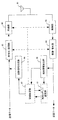
図1は、W−CDMAシステムの仕様の一つである非特許文献3で規定されている基地局と端末間で送受信される周波数情報を説明する図である。図1に示すように、FDDモードにおいて、下り周波数情報(図中「UARFCN downlink(Nd)」と表記。UARFCNはUTRA Absolute Radio Frequency Channel Numberの略記である)の移動通信装置への通知は必須(MP)とされ、上り周波数情報(図中「UARFCN uplink(Nu)」と表記)はオプション(OP)とされている。周波数差が一定(固定)でない場合には、上り周波数情報の通知は必須(MP)となる。下り周波数は、無線制御装置が決定し、基地局を介して端末に通知される。
FIG. 1 is a diagram for explaining frequency information transmitted and received between a base station and a terminal defined in
上り周波数を示す情報をNu、下り周波数を示す情報をNdと表し、設定範囲が0から16383であることから、これを表現するためには14ビット必要である。よって、14ビットの制御信号として端末に通知される。 Information indicating the upstream frequency is represented as Nu, information representing the downstream frequency is represented as Nd, and the setting range is from 0 to 16383, so 14 bits are required to represent this. Therefore, it is notified to the terminal as a 14-bit control signal.
これらの周波数情報Nu、Ndは、非特許文献1で規定され以下の式で作成される。
Nu=5×(FUL−FUL_offset) (1)
Nd=5×(FDL−FDL_offset) (2)
ここで、FUL、及びFDLはそれぞれ決定された周波数、FUL_offset及びFDL_offsetは図2にて規定されるオフセット周波数を表している。このため、図2は、周波数バンド毎の周波数差を説明する図であり、非特許文献1記載の表に、上り及び下り帯域の中心周波数と上りと下り周波数差の欄を追加したものである。These frequency information Nu and Nd are defined in
Nu = 5 × (F UL −F UL_offset ) (1)
Nd = 5 × (F DL −F DL_offset ) (2)
Here, F UL and F DL represent the determined frequencies, and F UL_offset and F DL_offset represent the offset frequencies defined in FIG. For this reason, FIG. 2 is a diagram for explaining the frequency difference for each frequency band. In the table described in
図2に表記の「i」〜「ix」はそれぞれ周波数バンド番号を表している。それにより図2は、周波数バンド毎に、アップリンク(UL:端末(UE)から基地局(Node B)に送信されるリンク)、ダウンリンク(DL:端末に基地局から送信されるリンク)にそれぞれ割り当てられた帯域、及びそれら帯域間の周波数差を示している。 In FIG. 2, “i” to “ix” represent frequency band numbers, respectively. Accordingly, FIG. 2 shows, for each frequency band, uplink (UL: a link transmitted from the terminal (UE) to the base station (Node B)) and downlink (DL: link transmitted from the base station to the terminal). Each assigned band and the frequency difference between these bands are shown.
上式を用いて、上り周波数が1922.4MHz、下り周波数が2112.4MHzの場合の周波数情報Nu、Nd算出すると以下となる。
Nu=5×(FUL−FUL_offset)=5×(1922.4−0)=9612 (3)
Nd=5×(FDL−FDL_offset)=5×(2112.4−0)=10562 (4)
W−CDMA方式では、端末の性能(端末性能)をカテゴリで分けている。ここで端末性能とは、同時通信可能な無線チャネル数など通信を行う上で必須の情報である。この情報を用いて複数のカテゴリに分類することにより、簡易に管理することを目的としている。例えば、図3は非特許文献3に記載されたHSDPA(High-Speed Downlink Packet Access)方式における従来のカテゴリ分けを説明する図、図4は非特許文献3に記載されたHSUPA(High-Speed Uplink Packet Access)方式におけるカテゴリ分けを説明する図である。HSDPA、及びHSUPAは共に、W−CDMAをより高速化させたものである。図3では、カテゴリ毎に、一度に受信可能な最大のHS−DSCH(High-Speed Downlink Shared CHannel)数、間欠受信する最小の伝送時間間隔(Minimum inter-TTI interval)、HS−DSCH送信ブロックの最大ビット数、ソフトチャネルの総ビット数が定められていることを示している。図4では、カテゴリ毎に、一度に送信可能な最大のE−DCH(Enhanced-Dedicated CHannel)数、最小SF(Spreading Factor)、サポートするE−DCHの伝送時間間隔(TTI)(TTIは10、及び2ms)、10msのTTIで送信されるE−DCH送信ブロックの最大ビット数、2msのTTIで送信されるE−DCH送信ブロックの最大ビット数が定められていることを示している。Using the above equation, frequency information Nu and Nd when the upstream frequency is 1922.4 MHz and the downstream frequency is 212.4 MHz are calculated as follows.
Nu = 5 × (F UL -F UL_offset) = 5 × (1922.4-0) = 9612 (3)
Nd = 5 × (F DL −F DL_offset ) = 5 × (2112.4-0) = 10562 (4)
In the W-CDMA system, terminal performance (terminal performance) is divided into categories. Here, the terminal performance is essential information for communication such as the number of radio channels that can be simultaneously communicated. This information is used for easy management by classifying into a plurality of categories. For example, FIG. 3 is a diagram for explaining conventional categorization in the HSDPA (High-Speed Downlink Packet Access) system described in Non-Patent
上記のようにカテゴリは、基地局と端末間の通信を適切に行うために必要不可欠な情報である。このため、カテゴリ情報(例えばカテゴリ番号)または端末性能情報は端末から基地局側に通知される。その通知は、送信相手を選択し送信方法を決定するスケジューリングに反映される。 As described above, the category is indispensable information for appropriately performing communication between the base station and the terminal. For this reason, category information (for example, category number) or terminal performance information is notified from the terminal to the base station side. The notification is reflected in scheduling for selecting a transmission partner and determining a transmission method.
最近では、実際に使用する上り周波数帯域幅(以降「上り帯域幅」)と下り周波数帯域幅(以降「下り帯域幅」)は異なるだけでなく、端末性能によっては可変とする通信システムが提案されている。例えば3GPPにおいて仕様化が検討されているE3G(Evolved 3G。S3G(Super 3G)とも称される)システムを挙げることができる。 Recently, a communication system has been proposed in which the uplink frequency bandwidth actually used (hereinafter “uplink bandwidth”) and the downlink frequency bandwidth (hereinafter “downlink bandwidth”) are not only different but also variable depending on the terminal performance. ing. For example, an E3G (Evolved 3G, also referred to as S3G (Super 3G)) system whose specification is being studied in 3GPP can be cited.
このE3Gシステムにおける、上りと下りの周波数差は、各帯域幅の割り当てや、各帯域の中心周波数に依存して変化する。そのため、従来のW−CDMAシステムとは異なり、下り周波数の選択により上り周波数を自動的に選択できない。即ち、上り周波数、下り周波数の設定を別々に実施しなければならないため、必要な制御情報が多くなって制御がより複雑化し、基地局側は上り周波数、下り周波数の各制御情報を端末に通知しなければならない。 In this E3G system, the frequency difference between upstream and downstream varies depending on the allocation of each bandwidth and the center frequency of each band. Therefore, unlike the conventional W-CDMA system, the uplink frequency cannot be automatically selected by selecting the downlink frequency. That is, since the uplink frequency and downlink frequency must be set separately, more control information is required and the control becomes more complicated, and the base station notifies each terminal of the control information of the uplink frequency and the downlink frequency. Must.
上記周波数設定は、伝搬環境やスケジューリング等により通信中でも変更される可能性があるため、周波数設定を高速に行う必要がある。周波数設定を高速に行うためには、送受信する制御情報の数をより少なくする、周波数情報(制御情報)はより少ないビット数で通知する、及び制御をより簡単化する、のうちの少なくとも一方を実現させることが重要と考えられる。従来では、(1)、(2)式により得られる周波数情報Nu、Ndの通知にはそれぞれ14ビット必要であることから、より少ないビット数でそれらの周波数情報Nu、Ndを端末側に通知できるようにすることも重要視すべきと考えられる。
本発明は、無線通信(移動通信)における周波数設定を高速に行えるようにするための技術を提供することを目的とする。
本発明の第1、及び第2の無線通信システムは共に、無線端末装置(以下「端末」)との間で通信を行うためのものであり、それぞれ以下の手段を具備する。An object of this invention is to provide the technique for enabling the frequency setting in radio | wireless communication (mobile communication) to be performed at high speed.
Both the first and second wireless communication systems of the present invention are for communicating with a wireless terminal device (hereinafter referred to as “terminal”), and each includes the following means.
第1の態様の無線通信システムは、無線基地局装置と無線端末装置との間で使用可能な送信周波数帯域幅及び受信周波数帯域幅の少なくとも一方を用いて端末カテゴリを特定するカテゴリ特定手段を具備する。 The wireless communication system according to the first aspect includes category specifying means for specifying a terminal category using at least one of a transmission frequency bandwidth and a reception frequency bandwidth that can be used between the wireless base station device and the wireless terminal device. To do.
第2の態様の無線通信システムは、無線基地局装置と無線端末装置との間で使用可能な送信周波数と受信周波数との差を用いて端末カテゴリを特定するカテゴリ特定手段を具備する。 The wireless communication system according to the second aspect includes category specifying means for specifying a terminal category using a difference between a transmission frequency and a reception frequency that can be used between the wireless base station device and the wireless terminal device .
本発明では、端末から端末カテゴリと関連付けた端末性能情報を送信させることにより、無線通信システム側で端末カテゴリを特定し、特定した端末カテゴリに基づいて、端末との間の回線設定を行うと共に、その回線設定に応じた制御信号(情報)をその端末に送信させる。その回線設定(無線通信における周波数設定)は、端末カテゴリと関連付けた1つ以上の設定項目での設定可能範囲を限定させた形で行わせる。そのように限定させることで、周波数設定はより簡易化される。そのため、周波数設定自体、より高速に行えるようになる。これは、スケジューリングの実施に伴う周波数設定を行う場合も同様である。端末性能情報は、上記設定項目のうちの少なくとも一つの内容を示す情報であり、例えば端末が受信可能な周波数帯域幅(送信周波数帯域幅)、及び端末が送信可能な周波数帯域幅(受信周波数帯域幅)の少なくとも一方、或いは端末が送受信可能な周波数の差(送信周波数と受信周波数の差)を採用することができる。 In the present invention, by transmitting the terminal capability information which associates a terminal category from the terminal to identify the terminal category in a wireless communication system side, based on the specified terminal category, performs line setting between the terminal Then, a control signal (information) corresponding to the line setting is transmitted to the terminal. The line setting (frequency setting in wireless communication) is performed in a form that limits the settable range in one or more setting items associated with the terminal category. By so limiting, the frequency setting is further simplified. Therefore, the frequency setting itself can be performed at a higher speed. The same applies to the case where the frequency setting associated with the scheduling is performed. The terminal performance information is information indicating the content of at least one of the setting items. For example, the frequency bandwidth that can be received by the terminal (transmission frequency bandwidth) and the frequency bandwidth that can be transmitted by the terminal (reception frequency band) Width) or a frequency difference (a difference between a transmission frequency and a reception frequency) that can be transmitted and received by the terminal can be employed.
以下、本発明の実施の形態について、図面を参照しながら詳細に説明する。
<第1の実施の形態>
図5は、第1の実施の形態による無線通信システムの構成を示す図である。その無線通信システムは、例えばE3Gに対応、つまりOFDMA(Orthogonal Frequency Division Multiple Access)に対応の移動通信サービスを実現させるためのものである。図5に示すように、移動端末装置(UE:User Equipment。以降「端末」と略記)52と通信を行う無線基地局(Node B。以降「基地局」と略記)51が複数、配置され、複数の基地局51を無線制御装置(RNC:Radio Network Controller)53により制御するようになっている。Hereinafter, embodiments of the present invention will be described in detail with reference to the drawings.
<First Embodiment>
FIG. 5 is a diagram illustrating a configuration of the wireless communication system according to the first embodiment. The wireless communication system is for realizing a mobile communication service compatible with, for example, E3G, that is, OFDMA (Orthogonal Frequency Division Multiple Access). As shown in FIG. 5, a plurality of radio base stations (Node B, hereinafter abbreviated as “base station”) 51 that communicate with a mobile terminal apparatus (UE: User Equipment; hereinafter abbreviated as “terminal”) 52 are arranged, A plurality of
図6は、上記端末に搭載された無線通信装置の構成図である。無線通信装置は図6に示すように、アンテナ61、2つの無線部62、及び63、符号化・変調部64、復調・復号部65、端末性能情報を格納した端末性能情報記憶部66、端末情報信号作成部67、制御信号抽出部68、及び装置設定制御部69、を備えている。以降は、端末性能情報にも格納先を明確にするために「66」を付して表記する。
FIG. 6 is a configuration diagram of a wireless communication apparatus mounted on the terminal. As shown in FIG. 6, the wireless communication apparatus includes an
送信の対象となる送信データは、符号化・変調部64によって符号化され、変調される。変調によって得られたRF信号が無線部62を介してアンテナ61から送信される。
一方、アンテナ61によって受信されたRF信号は、無線部63によって、選択された周波数帯域幅の信号分のみ抽出され、復調・復号部65に送られる。復調・復号部65は、無線部63からのRF信号を復調し、復号し、得られたデータを受信データとして出力する。Transmission data to be transmitted is encoded and modulated by the encoder /
On the other hand, the RF signal received by the
図7は、上記装置設定制御部の構成図である。図7に示すように、装置制御部69は、変復調方法・符号化復号方法算出部71、送受信周波数算出部72、送受信帯域幅算出部73、復調方法・復号方法設定部74、受信使用周波数設定部75、受信使用帯域幅設定部76、送信使用帯域幅設定部77、送信使用周波数設定部78、及び変調方法・符号化方法設定部79を備えている。
FIG. 7 is a configuration diagram of the device setting control unit. As shown in FIG. 7, the
図8は、上記基地局に搭載される無線通信装置の構成図である。図8に示すように、通信装置は、アンテナ81、2つの無線部82、及び83、復調・復号部85、符号化・変調部84、端末情報抽出部86、及び制御信号作成部88、を備えている。回線設定部87、及び端末カテゴリ設定部101は、基地局51側(無線通信システム側)に用意されるが、基地局51、及び無線制御装置52の何れに搭載されていても良いものである。本実施の形態による無線通信システムは、図8に示す無線通信装置を用意することで実現される。
FIG. 8 is a configuration diagram of a wireless communication apparatus mounted on the base station. As shown in FIG. 8, the communication apparatus includes an
送信の対象となる送信データは、符号化・変調部85によって符号化され、変調される。変調によって得られたRF信号が無線部83を介してアンテナ81から送信される。
一方、アンテナ81によって受信されたRF信号は、無線部83によって、選択された周波数帯域幅毎に抽出され、復調・復号部84に送られる。復調・復号部84は、無線部84からのRF信号を復調し、復号する。それによって得られたデータを受信データとして出力する。Transmission data to be transmitted is encoded and modulated by the encoder /
On the other hand, the RF signal received by the
図9は、上記回線設定部の構成図である。図9に示すように、その回線設定部87は、変復調方法・符号化復号方法算出部91、送受信周波数算出部92、送受信帯域幅算出部93、復調方法・復号方法設定部94、送信使用周波数設定部95、送信使用帯域幅設定部96、受信使用帯域幅設定部97、受信使用周波数設定部98、及び復調方法・復号方法設定部99を備えている。
FIG. 9 is a configuration diagram of the line setting unit. As shown in FIG. 9, the
上記端末52はE3Gに対応の端末カテゴリにより分類されるものである。実際に使用する上り周波数帯域幅(以降「上り帯域幅」)と下り周波数帯域幅(以降「下り帯域幅」)を別々に設定可能である。上り周波数帯域、下り周波数帯域はそれらの帯域幅に依存して変化することから、各帯域幅の情報の他に、帯域毎にその帯域を示す情報が必須となる。結果、各帯域幅が一定の場合と比較して、必要な制御情報は多くなり、制御は複雑化する。本実施の形態では、その制御の複雑化を以下のようにして抑えている。帯域を示す情報として、ここでは便宜的に、その帯域の中心周波数を想定することとする。その情報は、周波数帯域を特定可能であれば別のもの、例えば最小、或いは最大の周波数であっても良い。 The terminal 52 is classified according to a terminal category corresponding to E3G. The actually used uplink frequency bandwidth (hereinafter “uplink bandwidth”) and downlink frequency bandwidth (hereinafter “downlink bandwidth”) can be set separately. Since the upstream frequency band and the downstream frequency band change depending on their bandwidth, in addition to the information on each bandwidth, information indicating the bandwidth is essential for each bandwidth. As a result, compared with the case where each bandwidth is constant, more control information is required and the control is complicated. In the present embodiment, the complexity of the control is suppressed as follows. Here, for convenience, the center frequency of the band is assumed as information indicating the band. The information may be another one as long as the frequency band can be specified, for example, the minimum or maximum frequency.
図10は、本実施の形態における端末カテゴリに関連付けした端末性能情報を説明する図である。
本実施の形態では、図10に示すように、端末カテゴリに関連付けて、変調方式、下り帯域幅、上り帯域幅、及びそれら帯域間の最大周波数差を定めている。端末52には、変調方式、上り帯域幅、下り帯域幅、及び最大周波数差のうちの少なくとも一つを端末性能情報66として用意し、その情報66を端末情報信号作成部67により送信データ(端末情報信号)に変換して、予め定めたチャネルを用いて基地局51に送信する。ここでは便宜的に、図10に示す情報を総合端末カテゴリ情報と呼ぶことにする。FIG. 10 is a diagram illustrating terminal performance information associated with a terminal category in the present embodiment.
In this embodiment, as shown in FIG. 10, a modulation scheme, a downlink bandwidth, an uplink bandwidth, and a maximum frequency difference between these bands are determined in association with a terminal category. The terminal 52 prepares at least one of a modulation scheme, an uplink bandwidth, a downlink bandwidth, and a maximum frequency difference as
図10に示すように関連付けた各情報の内容数は、変調方式では2つ、上り/下り帯域幅、及び最大周波数差ではそれぞれ3つである。このため、変調方式の端末性能情報66は1ビットの情報として送信することが可能である。他の情報では、それぞれ2ビットの情報として送信することが可能である。
As shown in FIG. 10, the number of contents of each piece of information associated with each other is two for the modulation scheme, and three for the uplink / downlink bandwidth and the maximum frequency difference. For this reason, the
図7に示すように、復調・復号部65は、復調部65a、及び復号部65bを備え、符号化・変調部64は、変調部64a、及び符号化部64bを備えている。端末性能情報66は、装置設定制御部69を構成する各算出部71〜3に送られる。それにより、変復調方法・符号化復号方法算出部71は、端末性能情報66から、復調方法、復号方法を決定し、復調方法・復号方法設定部74を介して復調部65a、及び復号部65bを制御すると共に、変調方法、符号化方法を決定し、変調方法・符号化方法設定部79を介して変調部64a、符号化部64bを制御する。同様に、送受信周波数算出部72は、下り周波数(受信使用周波数(使用する下り周波数帯域の中心周波数))、及び上り周波数(送信使用周波数(使用する上り周波数帯域の中心周波数))を算出する。下り周波数算出結果を基に受信使用周波数設定部75において、受信無線部63内部にあるローカル発振器の発振周波数の設定信号を作成し、受信無線部63を制御する。同様に上り周波数算出結果を基に、送信使用周波数設定部78において、送信無線部62内部にあるローカル発振器の発振周波数の設定信号を作成し、無線部62を制御する。送受信帯域幅算出部73は、制御信号から、下り帯域幅、及び上り帯域幅を算出する。算出した受信帯域幅を基に、受信使用帯域幅設定部76は、受信無線部63内部のフィルタ及び復調部65a内部のフィルタの設定信号を算出し、受信無線部63と復調部65aの制御を行う。更に、復調部内部65a内部のFFTの設定信号を算出し、復調部65aの制御を行う。同様に算出した送信帯域幅を基に、送信使用帯域幅設定部78において、送信無線部62内部のフィルタ及び変調部64a内部のフィルタの設定信号を算出し送信無線部62と変調部64aの制御を行う。更に、変調部64a内部のFFT部の設定信号を算出し、変調部64aの制御を行う。
As shown in FIG. 7, the demodulation /
図8に示すように、端末情報信号作成部67を介して基地局51に送信された端末性能情報66は、受信されて復調・復号され、復調・復号部84から受信データとして出力される。端末情報抽出部86は、その受信データ中に存在する端末性能情報66を抽出し、端末カテゴリ設定部101に送る。その設定部101は、例えば図10に示すような総合端末カテゴリ情報を格納した記憶部を備えている。このため、抽出された端末性能情報66を用いて総合端末カテゴリ情報を参照することにより、その端末性能情報66を送信した端末52が属する端末カテゴリを特定し、その結果を回線設定部87に通知する。回線設定部87は、通知された端末カテゴリに従って、その端末52を対象とした回線設定を行うと共に、その端末52に送信すべき制御情報を制御信号作成部88に通知することにより、制御信号を作成させて送信させる。
As shown in FIG. 8, the
図9に示すように、符号化・変調部85は、変調部85a、及び符号化部85bを備え、復調・復号部84は、復調部84a、及び復号部84bを備えている。回線設定部87は、基本的には図7に示す装置設定制御部69と同様の構成となっている。端末カテゴリ設定部101が特定した端末カテゴリは、回線設定部87を構成する各算出部91〜3に送られる。それにより、変復調方法・符号化復号方法算出部91は、端末カテゴリから、変調方法、符号化方法を決定し、変調方法・符号化方法設定部94を介して符号化部85a、及び変調部85bを制御すると共に、復調方法、復号方法を決定し、復調方法・復号方法設定部99を介して復調部84a、復号部84bを制御する。同様に、送受信周波数算出部92は、下り周波数(受信使用周波数(使用する下り周波数帯域の中心周波数))、及び上り周波数(送信使用周波数(使用する上り周波数帯域の中心周波数))をそれぞれ決定することにより、送信使用周波数設定部95を介して無線部83を制御し、受信使用周波数設定部98を介して無線部82を制御する。送受信帯域幅算出部93は、下り帯域幅、及び上り帯域幅をそれぞれ決定することにより、送信使用帯域幅設定部96を介して無線部93及び変調部85aを制御し、受信使用帯域幅設定部97を介して無線部82及び復調部84aを制御する。
As shown in FIG. 9, the encoding / modulating
各算出部91〜3はそれぞれ、決定した内容を示す情報を制御情報として制御信号作成部88に通知する。それにより、通信に必要な制御情報を端末52に送信する。
図7に示すように、基地局51から送信された制御情報は、受信されて復調・復号され、復調・復号部65から受信データとして出力される。制御信号抽出部68は、その受信データ中に存在する制御情報を抽出し、装置設定制御部69に送る。それにより、制御情報を受信した以降、装置設定制御部69は、その制御情報に従って各部を制御する。Each of the
As shown in FIG. 7, the control information transmitted from the
以上のように本実施の形態では、端末カテゴリに、本来、含まれていない情報を関連付け、関連付けた情報を回線設定に反映させている。関連付ける情報の内容は、端末カテゴリによる分類を逸脱しないものに限定している。このため、端末の管理はより容易化し、その制御はより簡単化される。この結果、回線設定等の周波数設定もより高速に行える。 As described above, in the present embodiment, information that is not originally included is associated with the terminal category, and the associated information is reflected in the line setting. The contents of the associated information are limited to those that do not deviate from the classification by the terminal category. For this reason, the management of the terminal becomes easier and the control thereof becomes easier. As a result, frequency setting such as line setting can be performed at higher speed.
なお、本実施の形態では、端末性能情報66を基地局51に送信しているが、端末性能情報66の代わりに端末カテゴリを通知しても良い。その通知は、例えば図11に示すように、端末性能情報66から端末カテゴリを特定・設定する端末カテゴリ設定部111を用意し、その設定部111に端末情報信号作成部67、及び装置設定制御部69を対応させることで実現できる。
In this embodiment, the
ところで、上り/下りの帯域幅の組み合わせは多数、存在する。例えば、上り帯域幅として1.25MHz、2.5MHz、及び5.0MHzを想定し、下り帯域幅として5.0MHz、10MHz、及び20MHzを想定し、システム全体の帯域幅を下り20MHz、上り5MHzと想定した場合2GHz帯では、組み合わせ数は以下のように63通りとなる。 By the way, there are many combinations of upstream and downstream bandwidths. For example, assuming 1.25 MHz, 2.5 MHz, and 5.0 MHz as the upstream bandwidth, assuming 5.0 MHz, 10 MHz, and 20 MHz as the downstream bandwidth, the bandwidth of the entire system is 20 MHz downstream, and 5 MHz upstream. Assuming that in the 2 GHz band, the number of combinations is 63 as follows.
4×(4+2+1)+2×(4+2+1)+1×(4+2+1)=9×7=63
日本では、図2に示すように、使用可能周波数帯域が3つある。このため、帯域数を考慮すると、組み合わせ数は189(=63×3)通りとなる。全ての組み合わせを認識できるようにカテゴリ分けを行うと、カテゴリ数が非常に多くなり、その管理も煩雑となり、必要な制御情報の数の増大を招くことになる。これを回避するために、本実施の形態では図10に示すようなカテゴリ分けに抑えている。なお、上記の式における「4」「2」及び「1」はそれぞれ、例えば上り帯域幅では1.25MHzでは4つの位置、2.5MHzでは2つの位置、及び5.0MHzでは1つの位置を取ることが可能なことを意味している。4 × (4 + 2 + 1) + 2 × (4 + 2 + 1) + 1 × (4 + 2 + 1) = 9 × 7 = 63
In Japan, as shown in FIG. 2, there are three usable frequency bands. For this reason, in consideration of the number of bands, the number of combinations is 189 (= 63 × 3). If category classification is performed so that all combinations can be recognized, the number of categories becomes very large, management thereof becomes complicated, and the number of necessary control information increases. In order to avoid this, in this embodiment, the categorization as shown in FIG. 10 is suppressed. Note that “4”, “2”, and “1” in the above formula take, for example, four positions in the upstream bandwidth at 1.25 MHz, two positions at 2.5 MHz, and one position at 5.0 MHz. It means that it is possible.
無線技術の一つにMIMOがある。そのMIMOは「Multiple Input Multiple Output」の略称であり、複数のアンテナでデータの送信/受信を行うものである。このことから、端末カテゴリに関連付ける情報として、図18に示すように、MIMOを用いた送信が可能か否かを示すMIMO送信情報、MIMOを用いた受信が可能か否かを示すMIMO受信情報のうちの少なくとも一方をMIMO情報として加えても良い。或いは他の情報の代わりとして加えても良い。
<第2の実施の形態>
移動体通信では、移動体(端末)が異なる基地局がカバーするエリアに移動することがある。そのような移動に対応するためにハンドオーバが実施される。ハンドオーバ実施時には、周波数資源、つまり上り/下り周波数、それらの帯域幅のうちの少なくとも一つの割り当てを変更する場合がある。第2の実施の形態は、そのハンドオーバ実施時における周波数資源の割り当てを変更するために送受信する制御情報のビット数をより抑えるようにしたものである。One wireless technology is MIMO. The MIMO is an abbreviation of “Multiple Input Multiple Output”, and data is transmitted / received by a plurality of antennas. Therefore, as information associated with the terminal category, as shown in FIG. 18, MIMO transmission information indicating whether transmission using MIMO is possible, and MIMO reception information indicating whether reception using MIMO are possible. At least one of them may be added as MIMO information. Alternatively, it may be added as a substitute for other information.
<Second Embodiment>
In mobile communication, a mobile body (terminal) may move to an area covered by a different base station. A handover is implemented to accommodate such movement. When a handover is performed, there is a case where the allocation of frequency resources, that is, uplink / downlink frequencies and at least one of those bandwidths is changed. In the second embodiment, the number of bits of control information transmitted / received to change the allocation of frequency resources at the time of handover is further suppressed.
ハンドオーバ実施時には、端末は既に1つ以上の基地局と通信を行っている。つまり上り/下りの周波数や、それらの帯域幅が既に割り当てられている。第2の実施の形態は、そのことに着目し、制御情報に必要なビット数を削減して、その送信に要する時間をより短縮するようにしたものである。 At the time of handover, the terminal is already communicating with one or more base stations. That is, uplink / downlink frequencies and their bandwidths are already allocated. In the second embodiment, paying attention to this, the number of bits required for the control information is reduced, and the time required for the transmission is further reduced.
第2の実施の形態における端末、及び基地局の構成は基本的に第1の実施の形態と同じである。このため、第1の実施の形態と同じ、或いは基本的に同じものには第1の実施の形態で付した符号をそのまま用いて、第1の実施の形態から異なる部分にのみ着目する形で説明する。 The configurations of the terminal and the base station in the second embodiment are basically the same as those in the first embodiment. For this reason, the same or basically the same components as those in the first embodiment are used as they are, and the same reference numerals used in the first embodiment are used as they are, and only the portions different from those in the first embodiment are noted. explain.
図12は、第2の実施の形態における端末に搭載される無線通信装置の構成図である。図12に示すように、第1の実施の形態における構成に加えて、基地局51毎に受信データから受信電界強度を測定する受信電界強度測定部121、及びその測定部121による測定結果を基地局51側に通知するための受信電界強度情報作成部122を更に備えている。その作成部122により、測定結果が受信電界強度情報として基地局51に送信される。第2の実施の形態による無線端末装置は、端末52に図12に示す無線通信装置を搭載させることによって実現されている。これは後述する他の実施の形態でも同様である。
FIG. 12 is a configuration diagram of a wireless communication device mounted on a terminal according to the second embodiment. As shown in FIG. 12, in addition to the configuration in the first embodiment, the received electric field
一方、基地局51側は、図13に示すように、第1の実施の形態における構成に加えて、端末52から受信した受信電界強度情報を受信データ中から抽出するための受信電界強度情報抽出部131、及びその抽出部131が抽出した受信電界強度情報によりハンドオーバ実施の必要性を判断するハンドオーバ制御部132を備えている。
On the other hand, as shown in FIG. 13, the
ハンドオーバ制御部132は、基地局51、或いは無線制御装置53に用意されるものである。端末52から基地局51毎に送信された受信電界強度情報を参照することで、ハンドオーバの必要性を判断し、その判断結果を回線設定部87に通知する。通知を基に受信電界強度が最も大きい基地局51に端末52との通信を行わせる。このことから回線設定部87は、ハンドオーバの必要性が通知された場合に、通信を行うべき端末52との回線設定を行う。その端末52の端末性能情報66を用いて端末カテゴリを特定し回線を設定する。その回線設定の内容が前のものと異なれば、端末52に送信すべき制御情報を制御信号作成部88に送り、制御信号を送信する。
The
その制御信号としては、以下を送信させる。
下り周波数を示す情報をNdとすると、その下り周波数情報Ndは前述の(2)の式により作成する。The following is transmitted as the control signal.
Assuming that the information indicating the downlink frequency is Nd, the downlink frequency information Nd is created by the equation (2) described above.
同様に、上り周波数を示す情報をNuとすると、その上り周波数情報Nuは、下り周波数FDL、及び決定された上り周波数FULを用いて次式により作成する。
Nu=5×(FDL−FUL) (5)
下り周波数情報Ndは、上述したように14ビット必要である。しかし、上り周波数情報Nuは、図2中、上り/下りの周波数差が最大の490MHzとなる周波数バンド番号ivのUMTS 1.7/2.1の場合でも、
Nu=5×490=2450
となることから、12ビットで表現することができる。このため、上り周波数情報Nuを(2)式により作成する場合と比較して、ビット数を削減することができる。その削減により、回線設定等に伴う周波数設定もより高速に行えるようになる。それらの周波数情報Nu、Ndは、送受信周波数算出部92が算出する。Similarly, if the information indicating the uplink frequency is Nu, the uplink frequency information Nu is created by the following equation using the downlink frequency F DL and the determined uplink frequency F UL .
Nu = 5 × (F DL -F UL ) (5)
The downlink frequency information Nd requires 14 bits as described above. However, the uplink frequency information Nu is the UMTS 1.7 / 2.1 of the frequency band number iv having the maximum uplink / downlink frequency difference of 490 MHz in FIG.
Nu = 5 × 490 = 2450
Therefore, it can be expressed by 12 bits. For this reason, the number of bits can be reduced as compared with the case where the uplink frequency information Nu is created by the expression (2). By the reduction, the frequency setting accompanying the line setting or the like can be performed at a higher speed. The transmission / reception
上り/下り周波数情報Nu、Ndは、制御信号として端末52に送信され、制御信号抽出部68によって抽出される。装置設定制御部69は、上り/下り周波数情報Nu、Ndから上り周波数FULを算出し、その算出後に、下り周波数FDLを算出する。それにより、基地局51から送信された制御信号に従った設定を行う。それら周波数FUL、FDLの算出は、図7の送受信周波数算出部72が行う。The uplink / downlink frequency information Nu and Nd is transmitted as a control signal to the terminal 52 and extracted by the control
なお、本実施の形態では、下り周波数情報Ndとして、(5)式により作成される情報を上り周波数情報Nuと共に送信するようにしているが、その逆としても良い。つまり上り周波数情報Nuを(2)式と類似の式を用いて作成し、下り周波数情報Ndを(5)式と類似の式を用いて作成するようにしても良い。また、基地局側が上り/下り周波数のうちの一方を決定して端末52に通知し、端末52が他方を図10に示すような総合端末カテゴリ情報を参照して決定し通知するようにさせても良い。
<第3の実施の形態>
上記第1、及び第2の実施の形態では、上り及び下り周波数のうちの少なくとも一方を直接的に基地局51から端末52に通知するようにしている。これに対し第3の実施の形態は、予め基準として上り及び下り周波数のうちの少なくとも一方を定め、その定めた基準の周波数を用いて上り及び下り周波数を通知するようにして、制御情報(信号)の送信に必要なビット数をより削減するようにしたものである。In the present embodiment, as the downlink frequency information Nd, the information created by the equation (5) is transmitted together with the uplink frequency information Nu, but the reverse is also possible. That is, the uplink frequency information Nu may be created using a formula similar to the formula (2), and the downlink frequency information Nd may be created using a formula similar to the formula (5). Further, the base station side determines one of the uplink / downlink frequencies and notifies the terminal 52, and the terminal 52 determines and notifies the other with reference to the comprehensive terminal category information as shown in FIG. Also good.
<Third Embodiment>
In the first and second embodiments, at least one of the uplink and downlink frequencies is directly notified from the
第3の実施の形態における端末、及び基地局の構成は基本的に第1の実施の形態と同じである。このため、第1の実施の形態と同じ、或いは基本的に同じものには第1の実施の形態で付した符号をそのまま用いて、第1の実施の形態から異なる部分にのみ着目する形で説明する。ここでは、図2に示すように上り/下りの各周波数帯域、及び帯域間の周波数差が定められている場合を例にとって説明する。 The configurations of the terminal and base station in the third embodiment are basically the same as those in the first embodiment. For this reason, the same or basically the same components as those in the first embodiment are used as they are, and the same reference numerals used in the first embodiment are used as they are, and only the portions different from those in the first embodiment are noted. explain. Here, a case will be described as an example where each frequency band of uplink / downlink and the frequency difference between the bands are determined as shown in FIG.
基地局51側の回線設定部87では、回線使用状況等を考慮して、端末52に割り当てる下り周波数を決定する。この際、予め定められた周波数バンド番号、或いはその中心周波数と、その中心周波数と実際に決定された上り及び下り周波数との間の差のうちの少なくとも一方と、を用いて制御信号を作成する。その中心周波数は基準として用いられるものであることから以降「基準周波数」と呼ぶことにする。
The
1〜9の周波数バンド番号は4ビットで表現可能である。基準周波数と上り周波数との間の差は、最大システム帯域幅として70MHzを想定したとしても、8ビットで表現可能である。これは、例えば基準周波数をfS_DL、決定された下り周波数をfDL、その差を示す下り周波数情報をNdとし、その周波数情報Ndを次式により作成するような場合である。The
Nd=2×(fS_DL−fDL) (6)
このようなことから、下り周波数を示す制御情報は合計12ビットで表現することができる。このため、その制御情報をより少ないビット数で送信することができる。その結果、周波数設定もより高速に行えることとなる。Nd = 2 × (f S — DL −f DL ) (6)
For this reason, control information indicating the downlink frequency can be expressed by a total of 12 bits. Therefore, the control information can be transmitted with a smaller number of bits. As a result, the frequency can be set faster.
実際には、UMTS 800(周波数バンド番号vi)を基準にし、877.5MHzを中心周波数とする下り周波数帯域を決定した場合、基準周波数は中心周波数の880MHzとし、877.5MHzとの差分である2.5MHzを用いて制御情報を作成すると、バンド番号が6は“0110”と表現でき、2.5MHzは(6)式より“000000101”となるから、“0110000000101”となる。
Actually, when a downlink frequency band having a center frequency of 877.5 MHz is determined with reference to UMTS 800 (frequency band number vi), the reference frequency is set to 880 MHz of the center frequency, which is a difference from 877.5 MHz. When the control information is created using .5 MHz, the
なお、本実施の形態では、バンド番号+基準周波数の差、により制御情報を作成するようにしているが、その順序は逆としても良い。また、その差は、基準周波数と下り周波数の間の差としているが、基準周波数と上り周波数の間の差としても良い。その差は、周波数情報をNu、上りの基準周波数をfS_UL、決定された上り周波数をfULとすると、例えば
Nu=2×(fS_UL−fUL) (7)
により作成すれば良い。そのような周波数情報Nd、Nuは何れも必要とするビット数をより削減できることから、何れを送信させても良い。基準とする周波数バンドの番号、或いは基準周波数については、記憶装置に予め格納させるようにしても良い。
<第4の実施の形態>
移動体(無線)通信では、送信相手を選択し送信方法を決定するスケジューリングが行われるのが普通である。第4の実施の形態は、そのスケジューリングに対応するようにしたものである。In the present embodiment, the control information is created based on the difference between the band number and the reference frequency, but the order may be reversed. The difference is a difference between the reference frequency and the downlink frequency, but may be a difference between the reference frequency and the uplink frequency. The difference is, for example, Nu = 2 × (f S_UL −f UL ) (7) where Nu is the frequency information, f S_UL is the uplink reference frequency, and f UL is the determined uplink frequency.
Should be created. Since such frequency information Nd and Nu can both reduce the number of bits required, any of them may be transmitted. The reference frequency band number or reference frequency may be stored in advance in the storage device.
<Fourth embodiment>
In mobile (wireless) communication, scheduling for selecting a transmission partner and determining a transmission method is usually performed. The fourth embodiment corresponds to the scheduling.
第4の実施の形態における端末、及び基地局の構成は基本的に第1の実施の形態と同じである。このため、上記第2及び第3の実施の形態と同様に、第1の実施の形態と同じ、或いは基本的に同じものには第1の実施の形態で付した符号をそのまま用いて、第1の実施の形態から異なる部分にのみ着目する形で説明する。 The configurations of the terminal and base station in the fourth embodiment are basically the same as those in the first embodiment. For this reason, as in the second and third embodiments, the same or basically the same components as those in the first embodiment are used as they are. A description will be given in a manner that focuses only on portions that differ from the first embodiment.
図14は、第4の実施の形態における端末に搭載される無線通信装置の構成図である。図14に示すように、第1の実施の形態における構成に加えて、基地局51から送信されるパイロット信号の受信により、送信電力及び干渉電力を測定し、SIRを算出してCQI(Channel Quality Indicator)を測定するCQI測定部141、及びその測定結果を基地局51に送信するためのCQI作成部142を更に備えている。その作成部142により、CQIの測定結果がCQI情報として基地局51に送信される。その送信は、HS−DPCCH (Dedicated Physical Control CHannel(uplink) for HS-DSCH)上で行われる。
FIG. 14 is a configuration diagram of a wireless communication device mounted on a terminal according to the fourth embodiment. As shown in FIG. 14, in addition to the configuration in the first embodiment, the transmission power and the interference power are measured by receiving the pilot signal transmitted from the
一方、基地局51側は、図15に示すように、第1の実施の形態における構成に加えて、端末52から受信したCQI情報を受信データ中から抽出するためのCQI情報抽出部151、及びその抽出部151が抽出したCQI情報を用いてスケジューリングを行うスケジューラ部152を更に備えている。
On the other hand, the
スケジューラ部152は、CQI情報抽出部151が端末52毎に抽出したCQI情報を参照して、送信対象とする端末52を選択すると共に、変調方式、符号化率、データ長、帯域幅、使用周波数を端末カテゴリから選択する。その端末カテゴリは、端末52から端末情報信号として基地局51側に通知されるか、或いは端末52が送信した端末性能情報66により端末カテゴリ設定部101から通知される。その選択結果を制御信号作成部88に伝達することにより、制御信号として対応する端末52に送信する。そのように端末カテゴリ(端末性能情報66)により端末52を管理するため、第1の実施の形態と同様に、制御は簡易化される。その簡易化により、周波数設定もより高速に行えるようになる。
<第5の実施の形態>
OFDMAでは、周知のように、すべてのサブキャリアを全ユーザ(端末52)が共有し、各ユーザにとって伝送特性のよいサブキャリアを割り当てることにより、周波数利用効率を改善することができる。第5の実施の形態は、サブキャリアに着目して制御情報の作成を行うようにしたものである。The
<Fifth embodiment>
In OFDMA, as is well known, all users (terminal 52) share all subcarriers, and frequency utilization efficiency can be improved by assigning subcarriers with good transmission characteristics for each user. In the fifth embodiment, control information is generated by paying attention to subcarriers.
第5の実施の形態における端末、及び基地局の構成は基本的に第1の実施の形態と同じである。このため、上記第2〜第4の実施の形態と同様に、第1の実施の形態と同じ、或いは基本的に同じものには第1の実施の形態で付した符号をそのまま用いて、第1の実施の形態から異なる部分にのみ着目する形で説明する。 The configurations of the terminal and the base station in the fifth embodiment are basically the same as those in the first embodiment. For this reason, as in the second to fourth embodiments, the same or basically the same components as those in the first embodiment are used as they are. A description will be given in a manner that focuses only on portions that differ from the first embodiment.
図16は、サブキャリアに対するナンバリング例を示す図である。本実施の形態では、図16に示すように、周波数が低くなる程、小さい数の番号をサブキャリアに割り当てている。周波数が最低のサブキャリアに割り当てる番号は1である。ここでは、基地局51側、及び端末52はサブキャリア番号、その番号が割り当てられたサブキャリアの周波数、及びサブキャリア帯域幅は予め共有していることを前提としている。
FIG. 16 is a diagram illustrating an example of numbering for subcarriers. In the present embodiment, as shown in FIG. 16, a smaller number is assigned to a subcarrier as the frequency is lower. The number assigned to the subcarrier with the lowest frequency is 1. Here, it is assumed that the
基地局51側の回線設定部87は、例えば端末52から受信した端末性能情報66により特定される端末カテゴリを用いて総合端末カテゴリ情報(図10)を参照し、割り当てる上り及び下り帯域幅、上り及び下り周波数等、つまりグループを決定する。この際、例えば決定した下り周波数からグループの中心に位置するサブキャリアの番号を特定し、下り帯域幅からサブキャリア数を特定する。サブキャリア番号、及びサブキャリア数の特定は、上り周波数、及び上り帯域幅のときも同様に行われる。そのようにして特定されるサブキャリア番号、及びサブキャリア数を制御情報として制御信号作成部88に通知し送信させる。サブキャリア番号の特定は、送受信周波数算出部92が行い、サブキャリア数の特定は、送受信帯域幅算出部93が行う。
The
一方、端末52の制御信号抽出部68は、基地局51から受信した制御情報(信号)を受信データ中から抽出して装置設定制御部69に通知する。その制御信号中のサブキャリア番号、及びサブキャリア数はそれぞれ送受信周波数算出部72、及び送受信帯域幅算出部73に送られる。それにより、送受信周波数算出部72は、サブキャリア番号に対応する周波数を算出し、送受信帯域幅算出部73は、サブキャリア数に対応する帯域幅を算出する。
On the other hand, the control
このようなサブキャリア番号、及びサブキャリア数を制御情報(信号)として採用することにより、サブキャリア単位の資源の割り当てを任意に行うことができる。サブキャリア番号、及びサブキャリア数の表現に必要なビット数は全サブキャリア数に依存する。しかし、サブキャリア番号、及びサブキャリア数により周波数、帯域幅を個別に管理可能なことから、制御は簡単なものとすることができる。それにより、周波数設定もより高速に行えることとなる。 By employing such a subcarrier number and the number of subcarriers as control information (signal), it is possible to arbitrarily allocate resources in units of subcarriers. The number of bits necessary for expressing the subcarrier number and the number of subcarriers depends on the total number of subcarriers. However, since the frequency and bandwidth can be individually managed by the subcarrier number and the number of subcarriers, the control can be simplified. As a result, the frequency can be set faster.
なお、本実施の形態では、サブキャリア番号とサブキャリア数の組み合わせを制御信号として送信するようにしているが、別の組み合わせとしても良い。例えばサブキャリア番号の代わりにその周波数を採用しても良い。或いは、第3の実施の形態のように、基準周波数を予め定め、その基準周波数との差を採用しても良い。他には、図17に示すように、複数のサブキャリアをグルーピングし、各グループに固有の番号を割り当て、例えばサブキャリア番号とグループ番号の組み合わせを制御信号として送信するようにしても良い。各グループに割り当てた周波数帯域幅、及びその周波数軸上の位置は普通、固有のものであるから、グループ番号のみを制御信号として送信させても良い。そのグループ番号のみを通知したとしても、グループ毎に周波数帯域幅、及びその位置を特定するための情報を端末52側に用意することにより、端末52はグループ情報から対応する周波数帯域幅、及びその位置を特定することができる。このようなことから、制御信号として採用する情報は各種の変形を行うことができる。その制御信号の送信は、回線設定時に行っても良いが、スケジューリングによって送信する端末が決まった場合に行うようにしても良い。
<第6の実施の形態>
移動体通信では、回線設定時やハンドオーバ時のセル選択、及び待受時の同期は、基地局で使用可能な帯域幅の中心周波数を用いて行う場合がある。この際、基地局から共通パイロット信号を伝送するCPICH(Common Pilot Channel)、同期信号を伝送するSCH(Synchronization CHannel)、待受信号を伝送するPCH(Paging CHannel)、システム情報を伝送するBCH(Broadcast CHannel)、及び端末に対して着信の有無を通知するPICH(Paging Indicator CHannel)には予め定められた周波数(例えばシステム周波数バンドの中心周波数。以降「初期使用周波数」)が用いられる。基地局から端末への送信は予め定められた帯域幅(以降「初期使用帯域幅」)が用いられる。第6の実施の形態は、このことに着目して、制御情報の作成を行うようにしたものである。In this embodiment, the combination of the subcarrier number and the number of subcarriers is transmitted as a control signal, but another combination may be used. For example, the frequency may be adopted instead of the subcarrier number. Alternatively, as in the third embodiment, a reference frequency may be determined in advance and a difference from the reference frequency may be employed. Alternatively, as shown in FIG. 17, a plurality of subcarriers may be grouped, a unique number is assigned to each group, and for example, a combination of a subcarrier number and a group number may be transmitted as a control signal. Since the frequency bandwidth assigned to each group and its position on the frequency axis are usually unique, only the group number may be transmitted as a control signal. Even if only the group number is notified, by preparing information for specifying the frequency bandwidth and the position of each group on the terminal 52 side, the terminal 52 can detect the corresponding frequency bandwidth from the group information and The position can be specified. For this reason, the information employed as the control signal can be variously modified. The control signal may be transmitted at the time of line setting, but may be transmitted when a terminal to be transmitted is determined by scheduling.
<Sixth Embodiment>
In mobile communication, cell selection during line setup or handover, and synchronization during standby may be performed using the center frequency of the bandwidth that can be used by the base station. At this time, CPICH (Common Pilot Channel) for transmitting a common pilot signal from the base station, SCH (Synchronization CHannel) for transmitting a synchronization signal, PCH (Paging CHannel) for transmitting a standby signal, BCH (Broadcast for transmitting system information) A predetermined frequency (for example, the center frequency of the system frequency band; hereinafter referred to as “initial use frequency”) is used for the PICH (Paging Indicator CHannel) that notifies the terminal of the presence or absence of an incoming call. Transmission from the base station to the terminal uses a predetermined bandwidth (hereinafter referred to as “initial use bandwidth”). In the sixth embodiment, attention is paid to this point, and control information is created.
第6の実施の形態における端末、及び基地局の構成は基本的に第1の実施の形態と同じである。このため、上記第2〜第5の実施の形態と同様に、第1の実施の形態と同じ、或いは基本的に同じものには第1の実施の形態で付した符号をそのまま用いて、第1の実施の形態から異なる部分にのみ着目する形で説明する。 The configurations of the terminal and the base station in the sixth embodiment are basically the same as those in the first embodiment. For this reason, as in the second to fifth embodiments, the same or fundamentally the same as the first embodiment is used without changing the reference numerals given in the first embodiment. A description will be given in a manner that focuses only on portions that differ from the first embodiment.
上記各信号の送信に用いられる周波数、及び帯域幅は、基地局51から端末52にPCH等を用いて伝送される。その伝送は、例えば第2の実施の形態で説明したような制御信号を作成して行われる。なお、初期使用周波数、及び初期使用帯域幅については、端末側に予め記憶させておいても良い。
The frequency and bandwidth used for transmitting each signal are transmitted from the
無線回線を確立した後に周波数帯域を移動させる場合、その移動前に行われる上記信号の送信には周波数バンドの中心周波数が用いられる。第6の実施の形態では、その中心周波数を基準周波数として、第3の実施の形態のように制御信号を作成し送信する。また、使用する帯域幅を示す制御信号を作成して送信する。それにより、制御信号に必要なビット数をより削減できるようにして、周波数設定の高速化をより容易とさせている。図19は、使用周波数帯域を移動させる様子を説明する図である。 When a frequency band is moved after establishing a wireless line, the center frequency of the frequency band is used for transmission of the signal performed before the movement. In the sixth embodiment, a control signal is created and transmitted as in the third embodiment with the center frequency as a reference frequency. In addition, a control signal indicating the bandwidth to be used is created and transmitted. Thereby, the number of bits required for the control signal can be further reduced, and the frequency setting can be made faster. FIG. 19 is a diagram for explaining how to move the used frequency band.
なお、本実施の形態(第1〜第6の実施の形態)では、基地局51側(無線通信システム側)の回線設定部87、及びスケジューラ部152、並びに端末52の装置設定制御部69は何れも、プログラムを実行するCPU、或いはDSP等によって実現される。既存の無線通信システム、或いは端末の構成によっては、CPU、或いはDSP等に実行させるプログラムの変更により、本発明を適用させることが可能である。このことから、本発明による無線通信システム、或いは端末を実現させるためのプログラムを用意し、そのプログラムをフラッシュメモリ、或いはCD−ROM等の記録媒体に記録して配布するようにしても良い。或いは通信ネットワークを介して配信できるようにしても良い。
In the present embodiment (first to sixth embodiments), the
Claims (2)
無線基地局装置と無線端末装置との間で使用可能な送信周波数帯域幅及び受信周波数帯域幅の少なくとも一方を用いて端末カテゴリを特定するカテゴリ特定手段を
具備することを特徴とする無線通信システム。In a wireless communication system,
Wireless communication system characterized by having a category specifying means for specifying the terminal category using at least one of available transmit frequency bandwidth and receiving frequency bandwidth between a wireless base station apparatus and the wireless terminal device .
無線基地局装置と無線端末装置との間で使用可能な送信周波数と受信周波数との差を用いて端末カテゴリを特定するカテゴリ特定手段を
具備することを特徴とする無線通信システム。In a wireless communication system,
Wireless communication system characterized by having a category specifying means for specifying a terminal category using a difference between the reception frequency and available transmit frequencies between the radio base station apparatus and the wireless terminal device.
Applications Claiming Priority (1)
| Application Number | Priority Date | Filing Date | Title |
|---|---|---|---|
| PCT/JP2006/322494 WO2008056425A1 (en) | 2006-11-10 | 2006-11-10 | Wireless communication system and wireless terminal device |
Related Child Applications (1)
| Application Number | Title | Priority Date | Filing Date |
|---|---|---|---|
| JP2011239338A Division JP5392341B2 (en) | 2011-10-31 | 2011-10-31 | Wireless communication system |
Publications (2)
| Publication Number | Publication Date |
|---|---|
| JPWO2008056425A1 JPWO2008056425A1 (en) | 2010-02-25 |
| JP4893747B2 true JP4893747B2 (en) | 2012-03-07 |
Family
ID=39364254
Family Applications (1)
| Application Number | Title | Priority Date | Filing Date |
|---|---|---|---|
| JP2008542979A Active JP4893747B2 (en) | 2006-11-10 | 2006-11-10 | Wireless communication system |
Country Status (11)
| Country | Link |
|---|---|
| US (5) | US8923213B2 (en) |
| EP (2) | EP2903318B1 (en) |
| JP (1) | JP4893747B2 (en) |
| KR (3) | KR101323899B1 (en) |
| CN (1) | CN101536386B (en) |
| AU (3) | AU2006350677B2 (en) |
| CA (1) | CA2668705C (en) |
| ES (2) | ES2661677T3 (en) |
| IN (2) | IN2014KN01987A (en) |
| RU (5) | RU2427980C2 (en) |
| WO (1) | WO2008056425A1 (en) |
Families Citing this family (37)
| Publication number | Priority date | Publication date | Assignee | Title |
|---|---|---|---|---|
| EP2903318B1 (en) * | 2006-11-10 | 2017-10-18 | Fujitsu Limited | Wireless communication system and wireless terminal device |
| US20100086082A1 (en) * | 2007-04-26 | 2010-04-08 | Panasonic Corporation | Radio communication terminal device, radio communication base station device, and radio communication method |
| US8520559B2 (en) * | 2008-04-02 | 2013-08-27 | Alcatel Lucent | Method for routing via access terminals |
| CN102577555B (en) * | 2009-10-02 | 2015-09-16 | 富士通株式会社 | Wireless communications method in wireless communication system, base station apparatus, terminal installation and wireless communication system |
| CN102577455B (en) * | 2009-10-06 | 2015-08-19 | 株式会社Ntt都科摩 | Base station apparatus and user's set |
| JP4740365B2 (en) | 2009-10-26 | 2011-08-03 | シャープ株式会社 | Mobile station apparatus, base station apparatus, radio communication system, communication control method, communication control program, and processor |
| CA2783499C (en) * | 2009-12-07 | 2017-01-17 | Lg Electronics Inc. | Method and apparatus for transmitting and receiving a signal in a wireless communication system that supports plural component carriers |
| JP5094896B2 (en) | 2010-02-26 | 2012-12-12 | シャープ株式会社 | Mobile station apparatus, base station apparatus, communication control method, and integrated circuit |
| US8779901B2 (en) * | 2010-04-13 | 2014-07-15 | Sunrise Micro Devices, Inc. | Asymmetric RTT ranging with multipath correction |
| JP5342601B2 (en) * | 2011-05-02 | 2013-11-13 | 株式会社エヌ・ティ・ティ・ドコモ | Wireless base station, mobile device, communication control apparatus, and communication control method |
| EP2705711B1 (en) * | 2011-05-03 | 2020-05-20 | Telefonaktiebolaget LM Ericsson (publ) | Method and network nodes in a telecommunication system |
| US9491738B2 (en) * | 2012-02-03 | 2016-11-08 | Qualcomm Incorporated | Managing downlink and uplink resources for low cost user equipments |
| GB2500392B (en) * | 2012-03-19 | 2014-05-14 | Broadcom Corp | Filtering |
| CN103686754B (en) * | 2012-09-17 | 2019-04-23 | 中兴通讯股份有限公司 | A kind of band spreading capability reporting and the method and apparatus issued |
| GB2506403B (en) * | 2012-09-28 | 2018-01-03 | Sony Corp | Assigning mode of virtual channel operation to mobile terminal |
| KR20150082451A (en) * | 2012-12-03 | 2015-07-15 | 후지쯔 가부시끼가이샤 | Machine-type communication resource configuration method and device |
| GB2510138A (en) | 2013-01-24 | 2014-07-30 | Sony Corp | Allocating communications resources within different frequency ranges according to the relative capability of a communications device |
| JP5623595B2 (en) * | 2013-05-31 | 2014-11-12 | シャープ株式会社 | Mobile station apparatus, processor, wireless communication system, communication control method, communication control program, and base station apparatus |
| JP6253263B2 (en) * | 2013-05-31 | 2017-12-27 | 株式会社Nttドコモ | User device, base station, user device type information notification method, and user device type information reception method |
| JP6191324B2 (en) * | 2013-08-07 | 2017-09-06 | 富士通株式会社 | Signal analysis apparatus, signal analysis program, and signal analysis method |
| KR20160111991A (en) * | 2014-01-24 | 2016-09-27 | 후아웨이 테크놀러지 컴퍼니 리미티드 | Method, device and apparatus for determining downlink parameter |
| KR102230149B1 (en) | 2014-05-19 | 2021-03-22 | 에스케이텔레콤 주식회사 | Method and apparatus for determining frequency band |
| JP5954908B2 (en) * | 2014-09-22 | 2016-07-20 | シャープ株式会社 | Mobile station apparatus, communication control method, and base station apparatus |
| EP3297351B1 (en) | 2015-05-13 | 2023-09-20 | Fujitsu Limited | Radio communication system, base station, communication terminal, and radio communication system control method |
| WO2016185530A1 (en) * | 2015-05-15 | 2016-11-24 | 富士通株式会社 | Wireless communication system, wireless base station device, terminal device, and wireless communication method |
| KR20190035610A (en) * | 2016-07-26 | 2019-04-03 | 광동 오포 모바일 텔레커뮤니케이션즈 코포레이션 리미티드 | Signal transmission method and apparatus |
| US10827478B2 (en) * | 2016-08-10 | 2020-11-03 | Ntt Docomo, Inc. | User terminal and radio communication method |
| JP7084871B2 (en) * | 2016-09-29 | 2022-06-15 | 株式会社Nttドコモ | Terminals, base stations, wireless communication systems, and communication methods |
| KR102149630B1 (en) | 2016-11-05 | 2020-08-28 | 애플 인크. | Asymmetric bandwidth support and dynamic bandwidth adjustment |
| US10575182B2 (en) | 2016-11-08 | 2020-02-25 | Phazr, Inc. | Methods and systems for channel mapping in a communication network |
| KR20190100243A (en) | 2016-12-30 | 2019-08-28 | 광동 오포 모바일 텔레커뮤니케이션즈 코포레이션 리미티드 | Data transmission method and device |
| CN108633046B (en) * | 2017-03-24 | 2023-08-22 | 华为技术有限公司 | Method and device for transmitting signals |
| US10637445B2 (en) * | 2017-10-18 | 2020-04-28 | Phazr, Inc. | Signaling methods for communication systems with widely spaced downlink and uplink frequency channels |
| JP6714029B2 (en) * | 2018-03-22 | 2020-06-24 | 日本電信電話株式会社 | Interference power estimation method, interference power estimation device and program |
| JP7344870B2 (en) * | 2018-06-29 | 2023-09-14 | 株式会社Nttドコモ | Communication devices, communication methods, and systems |
| US11233559B2 (en) | 2018-12-07 | 2022-01-25 | Qualcomm Incorporated | Frequency offset adjustment for beam switching in wireless communications |
| US11368185B2 (en) * | 2019-07-17 | 2022-06-21 | Qualcomm Incorporated | Sharing frequency generator settings in networks |
Citations (3)
| Publication number | Priority date | Publication date | Assignee | Title |
|---|---|---|---|---|
| JP2004537875A (en) * | 2000-12-15 | 2004-12-16 | ブロードストーム テレコミュニケイションズ インコーポレイテッド | Multi-carrier communication with group-based subcarrier allocation |
| JP2006217173A (en) * | 2005-02-02 | 2006-08-17 | Matsushita Electric Ind Co Ltd | Base station device and resource allocating method |
| JP2006287754A (en) * | 2005-04-01 | 2006-10-19 | Ntt Docomo Inc | Radio communication apparatus and method |
Family Cites Families (161)
| Publication number | Priority date | Publication date | Assignee | Title |
|---|---|---|---|---|
| JP3480760B2 (en) * | 1995-03-30 | 2003-12-22 | 株式会社東芝 | Mobile communication system |
| US6356607B1 (en) * | 1995-06-05 | 2002-03-12 | Omnipoint Corporation | Preamble code structure and detection method and apparatus |
| JP3603529B2 (en) * | 1997-03-13 | 2004-12-22 | 株式会社日立製作所 | Communication method and wideband digital wireless communication terminal in wideband digital wireless system |
| US5914950A (en) * | 1997-04-08 | 1999-06-22 | Qualcomm Incorporated | Method and apparatus for reverse link rate scheduling |
| FI104135B (en) * | 1997-06-24 | 1999-11-15 | Nokia Mobile Phones Ltd | Time division multiple access radio systems |
| US5940391A (en) * | 1997-11-25 | 1999-08-17 | International Business Machines Corporation | Method and apparatus for reconfigurable and adaptive stream multicast |
| US6307867B1 (en) * | 1998-05-14 | 2001-10-23 | Telefonaktiebolaget Lm Ericsson (Publ) | Data transmission over a communications link with variable transmission rates |
| JP3422692B2 (en) | 1998-08-24 | 2003-06-30 | 日本電信電話株式会社 | Radio resource allocation control method |
| FI105250B (en) * | 1998-09-01 | 2000-06-30 | Nokia Networks Oy | A method for controlling the load on a telecommunications system |
| JP3417320B2 (en) | 1998-09-30 | 2003-06-16 | 三菱マテリアル株式会社 | Base wireless device, mobile wireless device, wireless communication method, and recording medium |
| EP1135964B1 (en) * | 1998-12-09 | 2005-05-25 | BRITISH TELECOMMUNICATIONS public limited company | Communications network |
| CN1124769C (en) * | 1999-03-08 | 2003-10-15 | 诺基亚网络有限公司 | Method for establishing a communication between a user equipment and a radio network |
| US6757270B1 (en) * | 1999-06-11 | 2004-06-29 | Lucent Technologies Inc. | Low back haul reactivation delay for high-speed packet data services in CDMA systems |
| RU2263409C2 (en) * | 1999-07-23 | 2005-10-27 | Каналь+Сосьетэ Аноним | Methods and device for data exchange |
| US6389068B1 (en) * | 2000-05-15 | 2002-05-14 | Motorola, Inc. | Sliced bandwidth distortion prediction |
| JP3662473B2 (en) * | 2000-05-12 | 2005-06-22 | 株式会社エヌ・ティ・ティ・ドコモ | Multicast service providing method and information distribution apparatus |
| JP2002077229A (en) | 2000-09-04 | 2002-03-15 | Matsushita Electric Ind Co Ltd | Information transmission method |
| US6947748B2 (en) * | 2000-12-15 | 2005-09-20 | Adaptix, Inc. | OFDMA with adaptive subcarrier-cluster configuration and selective loading |
| US7263063B2 (en) * | 2001-07-06 | 2007-08-28 | Sri International | Per hop behavior for differentiated services in mobile ad hoc wireless networks |
| JP2003030072A (en) * | 2001-07-18 | 2003-01-31 | Matsushita Electric Ind Co Ltd | Method and device for substituting remote control |
| US6614308B2 (en) * | 2001-10-22 | 2003-09-02 | Infineon Technologies Ag | Multi-stage, high frequency, high power signal amplifier |
| AU2002339751A1 (en) | 2001-11-09 | 2003-05-19 | Matsushita Electric Industrial Co., Ltd. | Methods for ensuring medium access in a wireless network |
| KR100413222B1 (en) * | 2001-12-27 | 2004-01-03 | 한국전자통신연구원 | Transmit method of request information for bandwidth allocation and mobile terminal using the same transmit method, and dynamic slot allocation method and base station of mobile communication system using the same allocation method |
| KR100832117B1 (en) * | 2002-02-17 | 2008-05-27 | 삼성전자주식회사 | Apparatus for transmitting/receiving uplink power offset in communication system using high speed downlink packet access scheme |
| US7720023B2 (en) * | 2002-05-07 | 2010-05-18 | Nokia Corporation | Telecommunication system and method for transmitting video data between a mobile terminal and internet |
| US7158810B2 (en) * | 2002-06-27 | 2007-01-02 | Nokia Corporation | Indication of user equipment capabilities before radio resource control connection |
| US9065537B2 (en) * | 2002-09-03 | 2015-06-23 | Broadcom Corporation | Method and system for calibrating a multi-mode, multi-standard transmitter and receiver |
| US7277694B2 (en) * | 2002-10-22 | 2007-10-02 | Qualcomm Incorporated | Method and apparatus for commencing shared or individual transmission of broadcast content in a wireless telephone network |
| US8249615B2 (en) * | 2002-10-25 | 2012-08-21 | At&T Mobility Ii Llc | Delivery of network services |
| JP2004193676A (en) * | 2002-12-06 | 2004-07-08 | Ntt Docomo Inc | Communication system, communication method, and mobile station |
| KR101028687B1 (en) * | 2002-12-26 | 2011-04-12 | 오끼 덴끼 고오교 가부시끼가이샤 | Voice communications system |
| JP4255276B2 (en) * | 2002-12-26 | 2009-04-15 | 沖電気工業株式会社 | Voice communication device, telephone and voice communication system |
| GB2398455B (en) * | 2003-02-11 | 2007-09-26 | Ipwireless Inc | Method, base station and mobile station for TDD operation in a communication system |
| JP2004254239A (en) * | 2003-02-21 | 2004-09-09 | Fujitsu Ltd | Line quality characteristic evaluating system |
| JP2004254243A (en) * | 2003-02-21 | 2004-09-09 | Fujitsu Ltd | Interference measurement evaluating system |
| KR100513177B1 (en) * | 2003-03-07 | 2005-09-07 | 주식회사 케이티프리텔 | A frequency band conversion relay apparatus and method thereof same |
| KR100665425B1 (en) | 2003-03-08 | 2007-01-04 | 삼성전자주식회사 | System and method for performing handover operation in a mobile communication system |
| OA13218A (en) * | 2003-07-10 | 2006-12-13 | Ari Kahn | Services and transactions in a telephony network. |
| KR101133632B1 (en) * | 2003-07-31 | 2012-04-10 | 파나소닉 주식회사 | Radio transmitter apparatus and modulation scheme selecting method |
| US20050043030A1 (en) * | 2003-08-22 | 2005-02-24 | Mojtaba Shariat | Wireless communications system |
| KR20050029112A (en) * | 2003-09-20 | 2005-03-24 | 삼성전자주식회사 | Method for uplink bandwidth request and allocation based on quality of service class in a broadband wireless access communication system |
| US7092353B2 (en) * | 2003-10-17 | 2006-08-15 | Qualcomm Incorporated | Carrier search methods and apparatus |
| US7599339B2 (en) * | 2003-11-12 | 2009-10-06 | Interdigital Technology Corporation | Method and system for transferring wireless transmit/receive unit-specific information |
| ATE390773T1 (en) * | 2004-01-22 | 2008-04-15 | Matsushita Electric Ind Co Ltd | METHOD FOR HARQ REPEAT TIME CONTROL |
| WO2005086403A1 (en) * | 2004-02-27 | 2005-09-15 | Telefonaktiebolaget L M Ericsson | Optimising resource usage in a packet switched network |
| EP1753179B1 (en) * | 2004-05-10 | 2015-09-23 | NTT DoCoMo, Inc. | Packet transmission control device |
| US8125946B2 (en) * | 2004-05-21 | 2012-02-28 | Samsung Electronics Co., Ltd. | Wireless network and mobile stations for implementing variable bandwidth service on demand |
| JP2005341432A (en) | 2004-05-28 | 2005-12-08 | Ntt Docomo Inc | Frequency selecting apparatus, mobile communication system and multi-band control method |
| KR100584336B1 (en) * | 2004-06-24 | 2006-05-26 | 삼성전자주식회사 | System and method for connection identification allocation in a broadband wireless access communication system |
| KR100675134B1 (en) * | 2004-09-02 | 2007-01-29 | 엘지노텔 주식회사 | Apparatus and method for scheduling variable data exchange of trunk in mobile communication system |
| GB2418105A (en) * | 2004-09-13 | 2006-03-15 | Fujitsu Ltd | Relative indicators used for scheduling of uplink transmissions |
| JP2006094003A (en) * | 2004-09-22 | 2006-04-06 | Ntt Docomo Inc | Mobile communication system, apparatus and method for allocating frequency band |
| JP4447416B2 (en) * | 2004-09-22 | 2010-04-07 | 株式会社エヌ・ティ・ティ・ドコモ | Multiband mobile communication system and transmitter |
| US8009752B2 (en) * | 2004-10-01 | 2011-08-30 | Qualcomm Incorporated | Multi-carrier incremental redundancy for packet-based wireless communications |
| WO2006046889A1 (en) * | 2004-10-25 | 2006-05-04 | Telefonaktiebolaget Lm Ericsson (Publ) | Radio quality based channel resource management |
| US7444165B2 (en) * | 2004-12-13 | 2008-10-28 | Broadcom Corporation | Method and system for providing broadcast services through a cellular and/or wireless network to a plurality of mobile devices via service provider integration |
| US7483716B2 (en) * | 2004-12-13 | 2009-01-27 | Broadcom Corporation | Method and system for mobile receiver architecture for US band cellular and VHF/UHF broadcasting |
| US7620396B2 (en) * | 2005-02-08 | 2009-11-17 | Cisco Technology, Inc. | Monitoring for radio frequency activity violations in a licensed frequency band |
| US7697896B2 (en) * | 2005-03-16 | 2010-04-13 | Sony Computer Entertainment Inc. | Communication apparatus preventing communication interference |
| JP4527067B2 (en) | 2005-03-31 | 2010-08-18 | 株式会社エヌ・ティ・ティ・ドコモ | Mobile station, transmission method, and mobile communication system |
| EP1869929B1 (en) * | 2005-04-13 | 2015-11-11 | Vringo Infrastructure Inc. | Techniques for radio link resource management in wireless networks carrying packet traffic |
| US7961700B2 (en) * | 2005-04-28 | 2011-06-14 | Qualcomm Incorporated | Multi-carrier operation in data transmission systems |
| GB2418806B (en) * | 2005-08-19 | 2006-09-27 | Ipwireless Inc | Duplex operation in a cellular communication system |
| WO2007035134A1 (en) * | 2005-09-19 | 2007-03-29 | Telefonaktiebolaget Lm Ericsson (Publ) | Method for setting power levels for user equipments |
| FI20055512A0 (en) * | 2005-09-27 | 2005-09-27 | Nokia Corp | Transmission control in a radio communication system |
| US8320359B2 (en) * | 2005-10-11 | 2012-11-27 | Telefonaktiebolaget L M Ericsson (Publ) | Synchronization channel scheme for super 3G |
| JP2007124578A (en) * | 2005-10-31 | 2007-05-17 | Ntt Docomo Inc | Transmission/reception bandwidth setting method in wireless communication system defining multiple signal bandwidths, mobile terminal, and base station |
| CN100551119C (en) | 2005-11-11 | 2009-10-14 | 上海贝尔阿尔卡特股份有限公司 | The method and the base station that are used for allocated bandwidth in the wireless single-hop self-return network |
| JP4607191B2 (en) * | 2005-12-14 | 2011-01-05 | 三菱電機株式会社 | Scheduling method, base station and terminal |
| ES2698362T3 (en) * | 2006-02-03 | 2019-02-04 | Guangdong Oppo Mobile Telecommunications Corp Ltd | Assignment of uplink resources in a mobile communication system |
| KR101358469B1 (en) * | 2006-02-07 | 2014-02-06 | 엘지전자 주식회사 | Method for selection and signaling of downlink and uplink bandwidth in wireless networks |
| US9258833B2 (en) * | 2006-02-09 | 2016-02-09 | Altair Semiconductor Ltd. | LTE/Wi-Fi coexistence |
| US20070191041A1 (en) * | 2006-02-16 | 2007-08-16 | Chapin John M | Frequency Allocation |
| US20090318087A1 (en) * | 2006-02-20 | 2009-12-24 | Mattila Heikki O | Method and Device for Preventing Interference at a Radio Receiver Device Caused by Several Radio Transmitter Devices |
| US8131306B2 (en) * | 2006-03-20 | 2012-03-06 | Intel Corporation | Wireless access network and method for allocating data subcarriers within a downlink subframe based on grouping of user stations |
| WO2007111540A1 (en) * | 2006-03-24 | 2007-10-04 | Telefonaktiebolaget L M Ericsson | Method and arrangement for managing a reference signal for uplink channel estimation in a communications system |
| US7680215B2 (en) * | 2006-04-06 | 2010-03-16 | Telefonaktiebolaget L M Ericsson (Publ) | Apparatus and method for efficient inter radio access technology operation |
| US7746956B2 (en) * | 2006-04-19 | 2010-06-29 | Broadcom Corporation | Method and system for bandwidth calibration for a phase locked loop (PLL) |
| EP2012551B1 (en) * | 2006-04-26 | 2015-09-02 | Mitsubishi Denki Kabushiki Kaisha | Wireless communication system and wireless communication apparatus |
| US7711373B2 (en) * | 2006-05-11 | 2010-05-04 | Nokia Corporation | Multiradio control interface |
| AU2007252473C1 (en) * | 2006-05-23 | 2010-12-16 | Sharp Kabushiki Kaisha | Mobile communication method, mobile station device, base station device, and mobile communication system |
| US7916675B2 (en) * | 2006-06-20 | 2011-03-29 | Nokia Corporation | Method and system for providing interim discontinuous reception/transmission |
| US8130705B2 (en) * | 2006-09-15 | 2012-03-06 | Qualcomm Incorporated | Method and apparatus for service capability modification |
| US20080109851A1 (en) * | 2006-10-23 | 2008-05-08 | Ashley Heather | Method and system for providing interactive video |
| US20080109841A1 (en) * | 2006-10-23 | 2008-05-08 | Ashley Heather | Product information display and product linking |
| ES2603090T3 (en) * | 2006-11-01 | 2017-02-23 | Fujitsu Limited | Wireless communications system |
| EP2903318B1 (en) * | 2006-11-10 | 2017-10-18 | Fujitsu Limited | Wireless communication system and wireless terminal device |
| CN102752814B (en) * | 2007-02-05 | 2016-06-01 | 日本电气株式会社 | Base station-to-base station handover method, radio communication system, DRX control method, base station and communication terminal |
| US8204036B2 (en) * | 2007-02-28 | 2012-06-19 | Motorola Mobility, Inc. | Method and apparatus for coexistence |
| US8009630B2 (en) * | 2007-03-05 | 2011-08-30 | Nokia Corporation | Apparatus, method and computer program product providing neighbor discovery, handover procedure and relay zone configuration for relay stations in a multi-hop network |
| US8213374B2 (en) * | 2007-04-24 | 2012-07-03 | Ntt Docomo, Inc. | Mobile communication method, radio base station, mobile station, and processor |
| GB2452022B (en) * | 2007-07-24 | 2012-03-28 | Nec Corp | DRX configuration |
| US8315234B2 (en) * | 2007-09-24 | 2012-11-20 | Wi-Lan, Inc. | Time multiplexing for coexistence within multiple communication systems |
| US7907572B2 (en) * | 2007-09-28 | 2011-03-15 | Intel Corporation | Collocated radio coexistence method |
| KR101420879B1 (en) * | 2007-11-29 | 2014-07-17 | 엘지전자 주식회사 | Method for Transmitting Data regarding Scheduling Information |
| IL190659A0 (en) * | 2008-04-07 | 2008-12-29 | Mariana Goldhamer | Wireless communication network with relay stations |
| JP4413975B2 (en) * | 2008-04-28 | 2010-02-10 | 株式会社エヌ・ティ・ティ・ドコモ | Mobile communication system, mobile communication method, mobile station, radio access network apparatus, and core network apparatus |
| US8489950B2 (en) * | 2008-08-06 | 2013-07-16 | Nokia Siemens Networks Oy | Discontinuous reception retransmission timer and method |
| TWI399115B (en) * | 2008-08-08 | 2013-06-11 | Innovative Sonic Ltd | Method and apparatus for improving drx functionality |
| US20100069112A1 (en) * | 2008-09-15 | 2010-03-18 | Texas Instruments Incorporated | Scheduling transmissions in coexisting wireless networks |
| US9042479B2 (en) * | 2008-10-16 | 2015-05-26 | Qualcomm Incorporated | Method and apparatus for avoiding interference between coexisting wireless systems |
| JP5069670B2 (en) * | 2008-10-31 | 2012-11-07 | 株式会社エヌ・ティ・ティ・ドコモ | Mobile communication system |
| ES2439867T3 (en) * | 2008-12-17 | 2014-01-27 | Telefonaktiebolaget L M Ericsson (Publ) | Control of the radio emission of a mobile terminal in a critical area |
| KR101255467B1 (en) * | 2008-12-24 | 2013-04-16 | 후지쯔 가부시끼가이샤 | Network device, communication device, communication control method, and communication control system |
| US8855570B2 (en) * | 2009-02-05 | 2014-10-07 | Telefonaktiebolaget L M Ericsson (Publ) | Coexistence of plural wireless communication transceivers in close proximity |
| JP2012519998A (en) * | 2009-03-04 | 2012-08-30 | センター オブ エクセレンス イン ワイアレス テクノロジー | Pilot assisted data transmission and reception including interference mitigation in wireless systems |
| KR101638911B1 (en) * | 2009-03-06 | 2016-07-12 | 엘지전자 주식회사 | Dual mode mobile terminal in mino wireless communication system and controlling method therefor |
| JP5268777B2 (en) * | 2009-05-19 | 2013-08-21 | 株式会社日立製作所 | Transceiver |
| US8787468B2 (en) * | 2009-06-19 | 2014-07-22 | Motorola Mobility Llc | Method and apparatus for multi-radio coexistence |
| US8886126B2 (en) * | 2009-07-09 | 2014-11-11 | Qualcomm Incorporated | Resolution algorithms for multi-radio coexistence |
| US8284725B2 (en) * | 2009-10-30 | 2012-10-09 | Intel Corporation | Techniques to negotiate capabilities between networked devices |
| CN102577555B (en) * | 2009-10-02 | 2015-09-16 | 富士通株式会社 | Wireless communications method in wireless communication system, base station apparatus, terminal installation and wireless communication system |
| CN102577455B (en) * | 2009-10-06 | 2015-08-19 | 株式会社Ntt都科摩 | Base station apparatus and user's set |
| JP4740365B2 (en) * | 2009-10-26 | 2011-08-03 | シャープ株式会社 | Mobile station apparatus, base station apparatus, radio communication system, communication control method, communication control program, and processor |
| US8942633B2 (en) * | 2009-10-26 | 2015-01-27 | Mediatek Inc. | Systems and methods for activity coordination in multi-radio terminals |
| US8462622B2 (en) * | 2009-12-08 | 2013-06-11 | Qualcomm Incorporated | Detection of co-located interference in a multi-radio coexistence environment |
| CN102118860B (en) * | 2009-12-31 | 2014-11-05 | 中兴通讯股份有限公司 | Duplex communication method as well as terminal scheduling method and system |
| WO2011087415A1 (en) * | 2010-01-14 | 2011-07-21 | Telefonaktiebolaget L M Ericsson (Publ) | Method and apparatus for providing access to public packet networks from a local environment |
| US8559323B2 (en) * | 2010-03-10 | 2013-10-15 | Cisco Technology, Inc. | Downlink OFDMA for service sets with mixed client types |
| US9420599B2 (en) * | 2010-03-24 | 2016-08-16 | Mediatek Inc. | Synchronized activity bitmap generation method for co-located coexistence (CLC) devices |
| US9282462B2 (en) * | 2010-03-31 | 2016-03-08 | Qualcomm Incorporated | Method and apparatus to facilitate support for multi-radio coexistence |
| US10911961B2 (en) * | 2010-03-31 | 2021-02-02 | Qualcomm Incorporated | Method and apparatus to facilitate support for multi-radio coexistence |
| US8838046B2 (en) * | 2010-06-18 | 2014-09-16 | Mediatek Inc. | System and method of hybrid FDM/TDM coexistence interference avoidance |
| US9924412B2 (en) * | 2010-06-18 | 2018-03-20 | Acer Incorporated | Method of handling buffer status report and communication device thereof |
| WO2011157235A1 (en) * | 2010-06-18 | 2011-12-22 | Mediatek Inc. | System and method for coordinating multiple radio transceivers within the same device platform |
| US8842546B2 (en) * | 2010-07-22 | 2014-09-23 | Mediatek Inc. | Method for wireless communication in a device with co-existence radio |
| US9497636B2 (en) * | 2010-07-26 | 2016-11-15 | Nokia Technologies Oy | Apparatus and method to reduce interference between disparate communication systems |
| US9246603B2 (en) * | 2010-08-12 | 2016-01-26 | Mediatek Inc. | Method of in-device interference mitigation for cellular, bluetooth, WiFi, and satellite systems coexistence |
| EP2604085B1 (en) * | 2010-08-13 | 2015-01-21 | InterDigital Patent Holdings, Inc. | In-device interference mitigation |
| WO2012023734A2 (en) * | 2010-08-16 | 2012-02-23 | 엘지전자 주식회사 | Method of avoiding idc interference in a wireless communication system and apparatus for same |
| US8886239B2 (en) * | 2010-09-21 | 2014-11-11 | Qualcomm Incorporated | Buffer status report control for creating transmission gaps |
| US8897220B2 (en) * | 2010-09-22 | 2014-11-25 | Qualcomm Incorporated | Multi-radio coexistence |
| WO2012042627A1 (en) * | 2010-09-30 | 2012-04-05 | 富士通株式会社 | Wireless communication device, wireless communication system, and wireless communication method |
| US8780880B2 (en) * | 2010-10-01 | 2014-07-15 | Mediatek Singapore Pte, Ltd. | Method of TDM in-device coexistence interference avoidance |
| WO2012061765A1 (en) * | 2010-11-05 | 2012-05-10 | Interdigital Patent Holdings, Inc. | Wtru measurements handling to mitigate in-device interference |
| US9113416B2 (en) * | 2010-11-10 | 2015-08-18 | Qualcomm Incorporated | System and method for reducing overhead of searcher tasks for discontinuous reception |
| US20130265984A1 (en) * | 2011-03-07 | 2013-10-10 | Honggang Li | Grouped machine-to-machine communications |
| CN103535071B (en) * | 2011-04-02 | 2017-02-15 | 高通股份有限公司 | Systems and methods for inter-radio access technology (RAT) mobility |
| WO2013006193A1 (en) * | 2011-07-01 | 2013-01-10 | Intel Corporation | Layer shifting in open loop multiple-input, multiple-output communications |
| US8725101B2 (en) * | 2011-07-06 | 2014-05-13 | Broadcom Corporation | Wireless device and method of operation |
| CN103947249B (en) * | 2011-09-30 | 2018-04-27 | 英特尔公司 | The method that internet service is simultaneously transmitted by multiple wireless networks |
| WO2013049768A1 (en) * | 2011-09-30 | 2013-04-04 | Interdigital Patent Holdings, Inc. | Device communication using a reduced channel bandwidth |
| US20130114571A1 (en) * | 2011-11-07 | 2013-05-09 | Qualcomm Incorporated | Coordinated forward link blanking and power boosting for flexible bandwidth systems |
| EP2603030B1 (en) * | 2011-12-09 | 2014-12-24 | Fujitsu Limited | Interference management in wireless communication networks |
| US9214977B2 (en) * | 2011-12-28 | 2015-12-15 | Empire Technology Development Llc | Reduction of cephalic absorption of radiation from mobile communication devices |
| US9055453B2 (en) * | 2012-02-03 | 2015-06-09 | Telefonaktiebolaget L M Ericsson (Publ) | Node and method for adapting parallel measurements with respect to an enhanced receiver |
| US8983448B2 (en) * | 2012-02-06 | 2015-03-17 | Samsung Electronics Co., Ltd. | In-device coexistence interference report control method and apparatus of network in mobile communication system |
| US9374829B2 (en) * | 2012-02-08 | 2016-06-21 | Qualcomm Incorporated | Multi-radio coexistence system to select ISM communications frequency bands to avoid cellular communications interference |
| US20130201883A1 (en) * | 2012-02-08 | 2013-08-08 | Qualcomm Incorporated | Multi-radio coexistence |
| US20130225068A1 (en) * | 2012-02-24 | 2013-08-29 | Nokia Corporation | Method, apparatus, and computer program product for coexistence-aware communication mechanism for multi-radios |
| US9433003B2 (en) * | 2012-03-07 | 2016-08-30 | Qualcomm Incorporated | Multi-radio coexistence via timing controls for radios using the same radio access technology |
| US20130242780A1 (en) * | 2012-03-16 | 2013-09-19 | Qualcomm Incorporated | Virtual gap patterns with multi-radio coexistence for protected measurements |
| US9363766B2 (en) * | 2012-03-29 | 2016-06-07 | Intel Deutschland Gmbh | Wireless communication interference mitigation |
| US9681382B2 (en) * | 2012-05-11 | 2017-06-13 | Intel Corporation | Radio coexistence in wireless networks |
| GB2502275B (en) * | 2012-05-21 | 2017-04-19 | Sony Corp | Telecommunications systems and methods |
| US9131522B2 (en) * | 2012-08-22 | 2015-09-08 | Qualcomm Incorporated | Time-frequency scheduling to improve multi-radio coexistence |
| US9131523B2 (en) * | 2012-08-22 | 2015-09-08 | Qualcomm Incorporated | Coexistence management using A-priori time domain information |
| GB2506176A (en) * | 2012-09-24 | 2014-03-26 | Nec Corp | Device to device (D2D) communication in a wireless communications network |
| EP2915355B1 (en) * | 2012-11-02 | 2019-07-31 | Telefonaktiebolaget LM Ericsson (publ) | Flexible spectrum support in cellular wireless communications |
| CN104349514B (en) * | 2013-07-26 | 2019-03-19 | 华为技术有限公司 | Multi-module radio terminal |
| GB2530198B (en) * | 2013-08-29 | 2016-06-22 | Nec Corp | Radio measurement reporting |
-
2006
- 2006-11-10 EP EP15159042.9A patent/EP2903318B1/en active Active
- 2006-11-10 ES ES06823316.2T patent/ES2661677T3/en active Active
- 2006-11-10 AU AU2006350677A patent/AU2006350677B2/en active Active
- 2006-11-10 KR KR1020117008335A patent/KR101323899B1/en active IP Right Grant
- 2006-11-10 KR KR1020097010883A patent/KR101089448B1/en active IP Right Grant
- 2006-11-10 KR KR1020127014258A patent/KR20120081226A/en active Search and Examination
- 2006-11-10 CA CA2668705A patent/CA2668705C/en active Active
- 2006-11-10 ES ES15159042.9T patent/ES2656130T3/en active Active
- 2006-11-10 WO PCT/JP2006/322494 patent/WO2008056425A1/en active Application Filing
- 2006-11-10 RU RU2009117329/09A patent/RU2427980C2/en active
- 2006-11-10 JP JP2008542979A patent/JP4893747B2/en active Active
- 2006-11-10 EP EP06823316.2A patent/EP2081395B1/en active Active
- 2006-11-10 CN CN2006800563221A patent/CN101536386B/en active Active
-
2009
- 2009-05-08 US US12/437,827 patent/US8923213B2/en active Active
-
2011
- 2011-01-17 RU RU2011101563/07A patent/RU2477013C2/en active
- 2011-04-19 AU AU2011201791A patent/AU2011201791B2/en active Active
- 2011-05-18 AU AU2011202315A patent/AU2011202315C1/en active Active
-
2012
- 2012-01-23 US US13/356,171 patent/US9326128B2/en active Active
- 2012-01-23 US US13/356,186 patent/US20120120897A1/en not_active Abandoned
- 2012-01-23 US US13/356,195 patent/US9549314B2/en active Active
- 2012-04-02 RU RU2012112837/08A patent/RU2496255C1/en active
- 2012-11-28 RU RU2012151154/07A patent/RU2545099C2/en active
-
2013
- 2013-08-01 RU RU2013136171/08A patent/RU2556467C2/en active
-
2014
- 2014-09-16 IN IN1987KON2014 patent/IN2014KN01987A/en unknown
- 2014-09-16 IN IN1986KON2014 patent/IN2014KN01986A/en unknown
-
2016
- 2016-07-25 US US15/218,433 patent/US10003961B2/en active Active
Patent Citations (3)
| Publication number | Priority date | Publication date | Assignee | Title |
|---|---|---|---|---|
| JP2004537875A (en) * | 2000-12-15 | 2004-12-16 | ブロードストーム テレコミュニケイションズ インコーポレイテッド | Multi-carrier communication with group-based subcarrier allocation |
| JP2006217173A (en) * | 2005-02-02 | 2006-08-17 | Matsushita Electric Ind Co Ltd | Base station device and resource allocating method |
| JP2006287754A (en) * | 2005-04-01 | 2006-10-19 | Ntt Docomo Inc | Radio communication apparatus and method |
Also Published As
Similar Documents
| Publication | Publication Date | Title |
|---|---|---|
| JP4893747B2 (en) | Wireless communication system | |
| JP5392341B2 (en) | Wireless communication system | |
| CA2787127C (en) | Wireless communication system and wireless terminal device | |
| AU2015243028B2 (en) | Wireless communication system and wireless terminal device | |
| CN102196416B (en) | Wireless communication system and wireless terminal device | |
| AU2011201686B2 (en) | Wireless communication system and wireless terminal device | |
| AU2014204545B2 (en) | Wireless communication system and wireless terminal device | |
| AU2012202258B2 (en) | Wireless communication system and wireless terminal device | |
| CN104270742B (en) | Wireless communication system and wireless terminal device |
Legal Events
| Date | Code | Title | Description |
|---|---|---|---|
| A131 | Notification of reasons for refusal |
Free format text: JAPANESE INTERMEDIATE CODE: A131 Effective date: 20110118 |
|
| A131 | Notification of reasons for refusal |
Free format text: JAPANESE INTERMEDIATE CODE: A131 Effective date: 20110830 |
|
| A521 | Request for written amendment filed |
Free format text: JAPANESE INTERMEDIATE CODE: A523 Effective date: 20111031 |
|
| TRDD | Decision of grant or rejection written | ||
| A01 | Written decision to grant a patent or to grant a registration (utility model) |
Free format text: JAPANESE INTERMEDIATE CODE: A01 Effective date: 20111122 |
|
| A01 | Written decision to grant a patent or to grant a registration (utility model) |
Free format text: JAPANESE INTERMEDIATE CODE: A01 |
|
| A61 | First payment of annual fees (during grant procedure) |
Free format text: JAPANESE INTERMEDIATE CODE: A61 Effective date: 20111205 |
|
| R150 | Certificate of patent or registration of utility model |
Ref document number: 4893747 Country of ref document: JP Free format text: JAPANESE INTERMEDIATE CODE: R150 Free format text: JAPANESE INTERMEDIATE CODE: R150 |
|
| FPAY | Renewal fee payment (event date is renewal date of database) |
Free format text: PAYMENT UNTIL: 20150106 Year of fee payment: 3 |