JP4891911B2 - Line-free cardiac stimulation system - Google Patents
Line-free cardiac stimulation system Download PDFInfo
- Publication number
- JP4891911B2 JP4891911B2 JP2007538089A JP2007538089A JP4891911B2 JP 4891911 B2 JP4891911 B2 JP 4891911B2 JP 2007538089 A JP2007538089 A JP 2007538089A JP 2007538089 A JP2007538089 A JP 2007538089A JP 4891911 B2 JP4891911 B2 JP 4891911B2
- Authority
- JP
- Japan
- Prior art keywords
- seed
- electrode assembly
- myocardium
- pacing
- tines
- Prior art date
- Legal status (The legal status is an assumption and is not a legal conclusion. Google has not performed a legal analysis and makes no representation as to the accuracy of the status listed.)
- Expired - Fee Related
Links
Images


Classifications
-
- A—HUMAN NECESSITIES
- A61—MEDICAL OR VETERINARY SCIENCE; HYGIENE
- A61N—ELECTROTHERAPY; MAGNETOTHERAPY; RADIATION THERAPY; ULTRASOUND THERAPY
- A61N1/00—Electrotherapy; Circuits therefor
- A61N1/02—Details
- A61N1/04—Electrodes
- A61N1/05—Electrodes for implantation or insertion into the body, e.g. heart electrode
- A61N1/0587—Epicardial electrode systems; Endocardial electrodes piercing the pericardium
- A61N1/059—Anchoring means
-
- A—HUMAN NECESSITIES
- A61—MEDICAL OR VETERINARY SCIENCE; HYGIENE
- A61N—ELECTROTHERAPY; MAGNETOTHERAPY; RADIATION THERAPY; ULTRASOUND THERAPY
- A61N1/00—Electrotherapy; Circuits therefor
- A61N1/18—Applying electric currents by contact electrodes
- A61N1/32—Applying electric currents by contact electrodes alternating or intermittent currents
- A61N1/36—Applying electric currents by contact electrodes alternating or intermittent currents for stimulation
- A61N1/362—Heart stimulators
- A61N1/365—Heart stimulators controlled by a physiological parameter, e.g. heart potential
-
- A—HUMAN NECESSITIES
- A61—MEDICAL OR VETERINARY SCIENCE; HYGIENE
- A61N—ELECTROTHERAPY; MAGNETOTHERAPY; RADIATION THERAPY; ULTRASOUND THERAPY
- A61N1/00—Electrotherapy; Circuits therefor
- A61N1/18—Applying electric currents by contact electrodes
- A61N1/32—Applying electric currents by contact electrodes alternating or intermittent currents
- A61N1/36—Applying electric currents by contact electrodes alternating or intermittent currents for stimulation
- A61N1/372—Arrangements in connection with the implantation of stimulators
- A61N1/37205—Microstimulators, e.g. implantable through a cannula
-
- A—HUMAN NECESSITIES
- A61—MEDICAL OR VETERINARY SCIENCE; HYGIENE
- A61N—ELECTROTHERAPY; MAGNETOTHERAPY; RADIATION THERAPY; ULTRASOUND THERAPY
- A61N1/00—Electrotherapy; Circuits therefor
- A61N1/18—Applying electric currents by contact electrodes
- A61N1/32—Applying electric currents by contact electrodes alternating or intermittent currents
- A61N1/36—Applying electric currents by contact electrodes alternating or intermittent currents for stimulation
- A61N1/372—Arrangements in connection with the implantation of stimulators
- A61N1/37211—Means for communicating with stimulators
- A61N1/37217—Means for communicating with stimulators characterised by the communication link, e.g. acoustic or tactile
- A61N1/37223—Circuits for electromagnetic coupling
-
- A—HUMAN NECESSITIES
- A61—MEDICAL OR VETERINARY SCIENCE; HYGIENE
- A61N—ELECTROTHERAPY; MAGNETOTHERAPY; RADIATION THERAPY; ULTRASOUND THERAPY
- A61N1/00—Electrotherapy; Circuits therefor
- A61N1/18—Applying electric currents by contact electrodes
- A61N1/32—Applying electric currents by contact electrodes alternating or intermittent currents
- A61N1/36—Applying electric currents by contact electrodes alternating or intermittent currents for stimulation
- A61N1/372—Arrangements in connection with the implantation of stimulators
- A61N1/37211—Means for communicating with stimulators
- A61N1/37235—Aspects of the external programmer
- A61N1/37241—Aspects of the external programmer providing test stimulations
-
- A—HUMAN NECESSITIES
- A61—MEDICAL OR VETERINARY SCIENCE; HYGIENE
- A61N—ELECTROTHERAPY; MAGNETOTHERAPY; RADIATION THERAPY; ULTRASOUND THERAPY
- A61N1/00—Electrotherapy; Circuits therefor
- A61N1/18—Applying electric currents by contact electrodes
- A61N1/32—Applying electric currents by contact electrodes alternating or intermittent currents
- A61N1/36—Applying electric currents by contact electrodes alternating or intermittent currents for stimulation
- A61N1/372—Arrangements in connection with the implantation of stimulators
- A61N1/37211—Means for communicating with stimulators
- A61N1/37252—Details of algorithms or data aspects of communication system, e.g. handshaking, transmitting specific data or segmenting data
- A61N1/37288—Communication to several implantable medical devices within one patient
-
- A—HUMAN NECESSITIES
- A61—MEDICAL OR VETERINARY SCIENCE; HYGIENE
- A61N—ELECTROTHERAPY; MAGNETOTHERAPY; RADIATION THERAPY; ULTRASOUND THERAPY
- A61N1/00—Electrotherapy; Circuits therefor
- A61N1/18—Applying electric currents by contact electrodes
- A61N1/32—Applying electric currents by contact electrodes alternating or intermittent currents
- A61N1/36—Applying electric currents by contact electrodes alternating or intermittent currents for stimulation
- A61N1/372—Arrangements in connection with the implantation of stimulators
- A61N1/375—Constructional arrangements, e.g. casings
- A61N1/37512—Pacemakers
-
- A—HUMAN NECESSITIES
- A61—MEDICAL OR VETERINARY SCIENCE; HYGIENE
- A61N—ELECTROTHERAPY; MAGNETOTHERAPY; RADIATION THERAPY; ULTRASOUND THERAPY
- A61N1/00—Electrotherapy; Circuits therefor
- A61N1/18—Applying electric currents by contact electrodes
- A61N1/32—Applying electric currents by contact electrodes alternating or intermittent currents
- A61N1/36—Applying electric currents by contact electrodes alternating or intermittent currents for stimulation
- A61N1/372—Arrangements in connection with the implantation of stimulators
- A61N1/375—Constructional arrangements, e.g. casings
- A61N1/3756—Casings with electrodes thereon, e.g. leadless stimulators
-
- A—HUMAN NECESSITIES
- A61—MEDICAL OR VETERINARY SCIENCE; HYGIENE
- A61N—ELECTROTHERAPY; MAGNETOTHERAPY; RADIATION THERAPY; ULTRASOUND THERAPY
- A61N1/00—Electrotherapy; Circuits therefor
- A61N1/18—Applying electric currents by contact electrodes
- A61N1/32—Applying electric currents by contact electrodes alternating or intermittent currents
- A61N1/36—Applying electric currents by contact electrodes alternating or intermittent currents for stimulation
- A61N1/372—Arrangements in connection with the implantation of stimulators
- A61N1/378—Electrical supply
- A61N1/3787—Electrical supply from an external energy source
-
- A—HUMAN NECESSITIES
- A61—MEDICAL OR VETERINARY SCIENCE; HYGIENE
- A61N—ELECTROTHERAPY; MAGNETOTHERAPY; RADIATION THERAPY; ULTRASOUND THERAPY
- A61N1/00—Electrotherapy; Circuits therefor
- A61N1/18—Applying electric currents by contact electrodes
- A61N1/32—Applying electric currents by contact electrodes alternating or intermittent currents
- A61N1/36—Applying electric currents by contact electrodes alternating or intermittent currents for stimulation
- A61N1/362—Heart stimulators
- A61N1/3627—Heart stimulators for treating a mechanical deficiency of the heart, e.g. congestive heart failure or cardiomyopathy
-
- A—HUMAN NECESSITIES
- A61—MEDICAL OR VETERINARY SCIENCE; HYGIENE
- A61N—ELECTROTHERAPY; MAGNETOTHERAPY; RADIATION THERAPY; ULTRASOUND THERAPY
- A61N1/00—Electrotherapy; Circuits therefor
- A61N1/18—Applying electric currents by contact electrodes
- A61N1/32—Applying electric currents by contact electrodes alternating or intermittent currents
- A61N1/36—Applying electric currents by contact electrodes alternating or intermittent currents for stimulation
- A61N1/372—Arrangements in connection with the implantation of stimulators
- A61N1/37211—Means for communicating with stimulators
- A61N1/37217—Means for communicating with stimulators characterised by the communication link, e.g. acoustic or tactile
- A61N1/37223—Circuits for electromagnetic coupling
- A61N1/37229—Shape or location of the implanted or external antenna
Landscapes
- Health & Medical Sciences (AREA)
- Life Sciences & Earth Sciences (AREA)
- Animal Behavior & Ethology (AREA)
- General Health & Medical Sciences (AREA)
- Biomedical Technology (AREA)
- Nuclear Medicine, Radiotherapy & Molecular Imaging (AREA)
- Radiology & Medical Imaging (AREA)
- Veterinary Medicine (AREA)
- Public Health (AREA)
- Engineering & Computer Science (AREA)
- Heart & Thoracic Surgery (AREA)
- Cardiology (AREA)
- Physics & Mathematics (AREA)
- Acoustics & Sound (AREA)
- Biophysics (AREA)
- Electromagnetism (AREA)
- Physiology (AREA)
- Electrotherapy Devices (AREA)
Abstract
Description
本出願は、参照により本明細書に組み込まれる、2004年10月20日に出願された米国特許出願第10/971,550号の一部継続出願である。
本明細書は、心臓または他の組織を電気的に刺激し、しかも、心臓または他の周辺組織または器官内に延ばされたリード(線、導線)を使用することなくそれを行うシステム、さらにはそのような刺激する手段を導入するためのシステムおよび方法に関する。
This application is a continuation-in-part of US patent application Ser. No. 10 / 971,550 filed Oct. 20, 2004, which is incorporated herein by reference.
The present specification provides a system for electrically stimulating a heart or other tissue, and for doing so without using a lead (wire, lead) extended into the heart or other surrounding tissue or organ, Relates to systems and methods for introducing such stimulating means.
ペースメーカーは、心臓組織に電気的刺激を与えて、心臓を収縮させ、そうして血液を送り出す。従来、ペースメーカーは、典型的には患者の胸部の皮膚真下に埋め込まれたパルス発生器を含む。1つまたは複数のリードが、パルス発生器から延びて心室内に、通常は右心室と右心房に入るが、ときには、左心室の上の静脈にも入る。電極は、リードの遠端にあって心臓組織と電気的に接触し、パルス発生器により発生され、リードを通じて電極に送られる電気パルスを与える。 The pacemaker applies electrical stimulation to the heart tissue to cause the heart to contract and thus pump blood. Traditionally, pacemakers typically include a pulse generator implanted directly under the skin of the patient's chest. One or more leads extend from the pulse generator into the ventricle, usually into the right and right ventricles, but sometimes into the vein above the left ventricle. The electrode is at the distal end of the lead and is in electrical contact with the heart tissue and provides an electrical pulse generated by a pulse generator and delivered to the electrode through the lead.
パルス発生器から延びて、心室に入るリードを使用する従来のやり方には、さまざまな欠点がある。例えば、リードは、その遠端に、医師がリードの位置を決める組織領域にリードを固定するための尖叉または「J字型フック」などの機構を備える。時間が経つうちに、心臓組織は、リードを適所に保持するためにリードと絡み合う。これは、医師によって選択された組織領域が確実に、患者退院後もペーシング(整調)される領域であり続けるという点で都合がよいが、リードに不具合が出た場合、または最初に選択された組織領域と異なる箇所をペーシングしたほうが望ましいと後から判明した場合には、不都合でもある。不具合の生じたリードは、感染、血栓症、弁機能障害などを含む、リードが心臓機能に及ぼす可能性のある潜在的有害反応を生じるため、患者体内に常に残すことはできない。したがって、異なるリード取り出し手順が、ときに使用されなければならない。 The conventional approach of using a lead extending from the pulse generator and entering the ventricle has various drawbacks. For example, the lead includes a mechanism at its distal end, such as a tines or “J-hook” for securing the lead to a tissue region where the physician positions the lead. Over time, the heart tissue entangles with the lead to hold the lead in place. This is convenient in that it ensures that the tissue area selected by the physician remains the area that is paced after the patient is discharged, but if the lead fails or was selected first It is also inconvenient if it is later discovered that pacing at a location different from the tissue area is desirable. A failed lead cannot always be left in the patient because it causes potential adverse reactions that the lead can have on cardiac function, including infection, thrombosis, valve dysfunction, and the like. Therefore, different lead removal procedures must sometimes be used.
リードの従来の使用では、さらに、電気エネルギーを送ることができる心臓組織の部位の数も制限される。リードの使用が制限となる理由は、リードは通常、心静脈内に配置されるということである。図17に示されているように、最大3本のリード2、3、および4が、心臓1の複数部位ペーシングを実行する従来のペーシングシステム内に埋め込まれ、これらのリードは上大静脈6を介して右心房5から出ている。複数のリードで、ペースメーカーインプラントに至る大静脈および分岐静脈の断面の臨床的に有意な部分が塞がる場合がある。
The conventional use of leads also limits the number of cardiac tissue sites that can deliver electrical energy. The reason the use of the lead is limited is that the lead is usually placed in the cardiac vein. As shown in FIG. 17, up to three leads 2, 3, and 4 are implanted in a conventional pacing system that performs multi-site pacing of the
心臓の左側の心室で使用することについては、市販のペーシングリードは指示されていなかった。これは、心臓の左側にかかる高いポンプ圧が、リードまたは電極上に形成した血栓または血餅を末梢動脈内に押し込んで、決定組織を送り、脳卒中または他の塞栓性損傷を引き起こす可能性があるからである。そのため、心臓の左側をペーシングするように設計されている、図17に示されているような従来のシステムは、ペーシングリード2を、右心房5内に配置されている、冠静脈洞入口部7に通し、また冠状静脈系8に通し、左側でペーシングされる部位上の静脈内の位置9に入れる。単一のリードは左心上をまたぐ静脈を局所的に塞ぐ可能性があるが、これは、他の静脈は、閉塞を代償し、心臓に送る血液量を増やすことができるという事実により解消される。しかしながら、複数のリードが静脈内に配置された場合、特に複数のリードを隣り合わせに並べることを必要とする冠静脈洞などの静脈内に著しい閉塞が生じる。
Commercial pacing leads were not indicated for use in the left ventricle of the heart. This can lead to high pump pressure on the left side of the heart pushing the thrombus or blood clot that forms on the lead or electrode into the peripheral arteries, sending the decisive tissue and causing a stroke or other embolic injury Because. Thus, a conventional system, such as that shown in FIG. 17, designed to pace the left side of the heart, has a
心臓組織の複数の部位におけるペーシングが有効な心臓の病気がいくつかある。このような病気の1つに、鬱血性心不全(CHF)がある。CHF患者に対しては、両心室ペーシング、つまり、時間的関係における左心室と右心室の両方のペーシングが有効であることが判明している。このような療法は、ここでは「再同期療法」と呼ばれている。左心室と右心室の複数の部位が同期ペーシングできれば、さらに多くの患者たちが恩恵を受けられると考えられる。それに加えて、複数の部位でのペーシングは、電気的エネルギーが伝搬して通らなければならない心臓組織が損なわれているか、または機能不全に陥っており、その状態がその心臓組織を通る電気的信号の伝搬を停止または変化させる場合に有効なことがある。これらの場合、複数部位ペーシングは、死んだ組織または病気の組織の領域のすぐ下流のところで電気的信号の伝搬を再開始する場合に有用である。心臓の複数部位での同期ペーシングは、緩徐または変行伝導から生じる細動の開始を阻害することができ、そのため、埋め込まれた、または外部除細動器の必要性が減じる。不整脈は、心室の緩徐伝導または拡張から生じうる。これらの疾病では、心室の周りで長いおよび/または遅い経路をとった脱分極波は、その組織が再分極する時間が経過した後、開始地点に戻ることができる。この方法で、決して終わることのない「レーストラック」または「サーカス」波が、正常な洞律動と同期しない1つまたは複数の心室内に存在しうる。一般的な、命に関わる状態である、心房細動は、このような伝導異常に関連することが多い。1つまたは複数の心室、例えば心房における十分な数の部位でペーシングを行うことで、同期方式ですべての組織の脱分極を強制的に行わせ、細動を引き起こすレーストラックおよびサーカス律動を防止することができる。 There are several heart conditions that are effective for pacing at multiple sites of heart tissue. One such disease is congestive heart failure (CHF). For CHF patients, biventricular pacing, that is, pacing both the left and right ventricles in a temporal relationship has been found to be effective. Such therapy is referred to herein as “resynchronization therapy”. More patients can benefit from synchronized pacing of multiple parts of the left and right ventricles. In addition, pacing at multiple sites is a compromised or dysfunctional heart tissue through which electrical energy must propagate and pass through, and the condition is an electrical signal that passes through the heart tissue. This may be useful when stopping or changing the propagation of In these cases, multi-site pacing is useful when reinitiating electrical signal propagation just downstream of the area of dead or diseased tissue. Synchronous pacing at multiple parts of the heart can inhibit the onset of fibrillation resulting from slow or inductive conduction, thus reducing the need for implanted or external defibrillators. Arrhythmias can result from slow conduction or dilatation of the ventricles. In these diseases, a depolarized wave that takes a long and / or slow path around the ventricle can return to the starting point after the time for the tissue to repolarize. In this way, a never-ending “race track” or “circus” wave may exist in one or more ventricles that are not synchronized with normal sinus rhythm. Atrial fibrillation, a common life-threatening condition, is often associated with such conduction abnormalities. Pacing at a sufficient number of sites in one or more ventricles, such as the atrium, forces all tissues to depolarize in a synchronized manner, preventing racetrack and circus rhythms that cause fibrillation be able to.
心臓組織を刺激するために心臓の心外膜面に取り付けられる、線無し(無線の)電極を使用するシステムは、停止を引き起こす制限を解消する一手段として提案されている。提案されているシステムでは、線無し電極は、中央ペーシング制御装置に取り付けられた高周波(RF)アンテナへの電極内のコイルを誘導結合を介してペーシング電気パルスを発生させるためのエネルギーを受け取る。線無し電極は、心臓壁の外面内にねじ込まれる。 Systems using wireless (wireless) electrodes that are attached to the epicardial surface of the heart to stimulate heart tissue have been proposed as a means of overcoming the limitations that cause arrest. In the proposed system, a wireless electrode receives energy to generate a pacing electrical pulse via inductive coupling of a coil in the electrode to a radio frequency (RF) antenna attached to a central pacing controller. The wireless electrode is screwed into the outer surface of the heart wall.
本発明は、線無し電極を使用してペーシング療法を行い、商業的に実施可能な、システムのさまざまな構成を対象とする。発明者らが得た研究成果の1つは、商業的に実施可能なシステムを実現する際に考慮すべき重要な問題点は埋め込まれたシステムの総合エネルギー効率であるということである。例えば、2つの誘導結合コイルのエネルギー伝達効率は、コイル間の距離が増えるとともに劇的に減少する。そのため、例えば、通常の上側胸部内に埋め込まれた送信機コイルは、無視できるくらい小さなエネルギーを心臓内に配置されている小型シード電極コイルに結合することしかできない。 The present invention is directed to various configurations of systems that can be paced using a wireless electrode and commercially implemented. One of the research results obtained by the inventors is that an important issue to consider when implementing a commercially viable system is the overall energy efficiency of the embedded system. For example, the energy transfer efficiency of two inductively coupled coils decreases dramatically as the distance between the coils increases. So, for example, a transmitter coil implanted in the normal upper chest can only couple negligible energy to a small seed electrode coil placed in the heart.
本発明の一態様は、線無し電極組立体の少なくとも一部を心内膜の組織に通して、心筋の組織内に埋め込むためのカテーテル送達システムを含むことができる。カテーテル送達システムは、近位端および遠位端を持ち、中を通る管腔を定める第1の細長い部材を備えることができる。システムは、さらに、近位端および遠位端を持つ第2の細長い部材を備えることもできる。システムは、さらに、第2の細長い部材の遠位端に取付け可能な線無し電極組立体を備えることができる。電極組立体が第2の細長い部材に取り付けられるときに、第2の細長い部材は、管腔に通すことが可能であり、それにより、電極組立体の少なくとも一部を心内膜に通し、心筋に送達することができる。 One aspect of the present invention can include a catheter delivery system for passing at least a portion of a wireless electrode assembly through endocardial tissue and into the myocardial tissue. The catheter delivery system can include a first elongate member having a proximal end and a distal end and defining a lumen therethrough. The system can further comprise a second elongate member having a proximal end and a distal end. The system can further comprise a wireless electrode assembly attachable to the distal end of the second elongate member. When the electrode assembly is attached to the second elongate member, the second elongate member can be passed through the lumen, thereby passing at least a portion of the electrode assembly through the endocardium and the myocardium. Can be delivered to.
いくつかの実施形態では、電極組立体は、心内膜を貫通し、心筋内に入る少なくとも1つの留め具を持つ取付け機構を備えることができる。この取付け機構は、電極組立体の少なくとも一部を心筋に固定するように動作可能である。いくつかの場合において、取付け機構は、少なくとも1つのらせん状尖叉および少なくとも1つの渦巻き状尖叉を備えることができる。例えば、取付け機構は、心内膜を貫通し、心筋に入る遠位に延びるらせん状尖叉および複数の放射状に延びる渦巻き状尖叉を備えることができる。他の場合には、取付け機構の留め具は、尖叉、ネジ、釣り針、またはフックを含むことができる。 In some embodiments, the electrode assembly can include an attachment mechanism having at least one fastener that penetrates the endocardium and enters the myocardium. The attachment mechanism is operable to secure at least a portion of the electrode assembly to the myocardium. In some cases, the attachment mechanism can comprise at least one helical tin and at least one spiral tin. For example, the attachment mechanism can comprise a distally extending helical tines and a plurality of radially extending spiral tines that penetrate the endocardium and enter the myocardium. In other cases, attachment mechanism fasteners may include tines, screws, fishhooks, or hooks.
他の実施形態では、第2の細長い部材は、電極組立体を心筋に送達した後、第2の細長い部材から電極組立体を外すため遠位端に脱離機構を備えることができる。いくつかの場合において、脱離機構は、電極組立体の一部と解放可能なように係合するネジ付き部材を備えることができる。他の場合において、脱離機構は、電極組立体の一部と解放可能なように係合する調節可能固定部材を備えることができる。 In other embodiments, the second elongate member can include a detachment mechanism at the distal end to disengage the electrode assembly from the second elongate member after delivering the electrode assembly to the myocardium. In some cases, the detachment mechanism can comprise a threaded member that releasably engages a portion of the electrode assembly. In other cases, the detachment mechanism can include an adjustable securing member that releasably engages a portion of the electrode assembly.
いくつかの実施形態では、第1の細長い部材は、第1の細長い部材の遠位端を心内膜に近い選択された部位に導くための操縦機構を備える。第1の細長い部材は、心内膜に近い選択された部位のところで局所心電図を感知するため遠位端に電極を備えることができる。 In some embodiments, the first elongate member comprises a steering mechanism for directing the distal end of the first elongate member to a selected site near the endocardium. The first elongate member can include an electrode at the distal end for sensing a local electrocardiogram at a selected site near the endocardium.
いくつかの実施形態では、このシステムは、近位端および遠位端を持つ、中を通る管腔を備える、アクセスカテーテルも備える。第1の細長い部材は、アクセスカテーテルの管腔を通ることができる送達カテーテルであってよい。画像装置を、アクセスカテーテルの遠位端近くに配置することができる。画像装置は、アクセスカテーテルの遠位にある選択された部位の視覚化を行うための超音波装置を含むことができる。 In some embodiments, the system also includes an access catheter comprising a lumen therethrough having a proximal end and a distal end. The first elongate member may be a delivery catheter that can pass through the lumen of the access catheter. An imaging device can be placed near the distal end of the access catheter. The imaging device can include an ultrasound device for visualizing selected sites distal to the access catheter.
他の態様では、埋め込み可能な線無し電極組立体は、ペーシング電気パルスを放出する第1の電極を備えることができる。この組立体は、心内膜組織を貫通し、心筋組織内に入る少なくとも1つの留め具を持つ取付け機構を備えることもできる。取付け機構の少なくとも一部は、留め具が心内膜を貫通し、心筋内に入るときに、電極が心筋の近くに位置するように電極の近くに配置することができる。 In other aspects, the implantable wireless electrode assembly can comprise a first electrode that emits a pacing electrical pulse. The assembly can also include an attachment mechanism having at least one fastener that penetrates the endocardial tissue and enters the myocardial tissue. At least a portion of the attachment mechanism can be positioned near the electrode so that the electrode is positioned near the myocardium as the fastener penetrates the endocardium and enters the myocardium.
いくつかの実施形態では、線無し電極組立体は、第2の電極も含む。第2の電極は、留め具が心内膜を貫通し、心筋に入るときに、第2の電極が内部心室内の血液に曝されている間に、第1の電極が心筋に近いところに位置決めされるように、第1の電極から相隔てて並べることができる。 In some embodiments, the lineless electrode assembly also includes a second electrode. The second electrode is positioned near the myocardium while the fastener penetrates the endocardium and enters the myocardium while the second electrode is exposed to blood in the internal ventricle. The first electrode can be spaced apart so that it is positioned.
他の実施形態では、線無し電極組立体は、さらに、外部エネルギー発生源から電磁エネルギーを受け取る誘導装置を備えることもできる。第1の電極は、ペーシング電気パルスが、誘導装置に届く電磁エネルギーの少なくとも一部から発生されるように回路に電気的に接続することができる。回路は、誘導装置に届く電磁エネルギーを蓄積するためのエネルギー蓄積要素を備えることができる。エネルギー蓄積要素は、電気エネルギーを周期的に電極に放出するように動作することが可能である。 In other embodiments, the wireless electrode assembly may further comprise an inductive device that receives electromagnetic energy from an external energy source. The first electrode can be electrically connected to the circuit such that pacing electrical pulses are generated from at least a portion of the electromagnetic energy that reaches the induction device. The circuit may comprise an energy storage element for storing electromagnetic energy that reaches the induction device. The energy storage element is operable to periodically release electrical energy to the electrode.
いくつかの実施形態では、線無し電極組立体は、外部エネルギー発生源に誘導結合されたコイルを備える誘導装置を備えることができる。
いくつかの実施形態では、線無し電極組立体は、少なくとも1つのらせん状尖叉および少なくとも1つの渦巻き状尖叉を備える取付け機構を備えることができる。取付け機構は、心内膜を貫通し、心筋に入る遠位に延びるらせん状尖叉を含み、またらせん状尖叉が心筋に貫通した後、心内膜または心筋内にカールして入るように適合された複数の放射状に延びる尖叉を含むことができる。
In some embodiments, the wireless electrode assembly can include an induction device that includes a coil inductively coupled to an external energy source.
In some embodiments, the wireless electrode assembly can include an attachment mechanism that includes at least one helical tine and at least one spiral tine. The attachment mechanism includes a distally extending spiral tine that penetrates the endocardium and enters the myocardium so that the spiral tine penetrates the myocardium and then curls into the endocardium or myocardium. A plurality of adapted radially extending tines can be included.
他の実施形態では、線無し電極組立体は、尖叉、ネジ、釣り針、またはフックを含む取付け機構を備えることができる。
他の実施形態では、線無し電極組立体は、さらに、取付け機構の留め具から相隔てて並ぶ脱離機構も備える。脱離機構は、ネジ付き部材を含み、留め具が心内膜を貫通して心筋内に入った後、線無し電極組立体を送達システムから解放するように動作可能なものとすることができる。
In other embodiments, the wireless electrode assembly can include an attachment mechanism that includes a tines, screws, fishhooks, or hooks.
In other embodiments, the wireless electrode assembly further includes a detachment mechanism that is spaced apart from a fastener of the attachment mechanism. The detachment mechanism can include a threaded member and can be operable to release the wireless electrode assembly from the delivery system after the fastener has penetrated the endocardium into the myocardium. .
さらに他の態様は、線無し電極組立体を内部心室内に送り、心筋に近づける方法を含むことができる。この方法は、第1の細長い部材の遠位端を内部心室内に導くことを含むことができる。第1の細長い部材は、遠位端、近位端、およびその中を通る管腔を備えることができる。この方法は、さらに、線無し電極組立体を第1の細長い部材の管腔に通し、第1の細長い部材の遠位端へと導くことも含むことができる。この方法は、さらに、線無し電極組立体の少なくとも一部を心内膜の組織に貫通させて、心筋内に入れることを含むことができる。 Yet another aspect can include a method of delivering a wireless electrode assembly into the internal ventricle and approaching the myocardium. The method can include directing the distal end of the first elongate member into the inner ventricle. The first elongate member can comprise a distal end, a proximal end, and a lumen therethrough. The method can further include directing the wireless electrode assembly through the lumen of the first elongate member to the distal end of the first elongate member. The method may further include penetrating at least a portion of the wireless electrode assembly through the endocardial tissue into the myocardium.
いくつかの実施形態では、この方法は、さらに、第2の細長い部材の遠位端に取り付けられた線無し電極組立体を使用することができる。第2の細長い部材は、第1の細長い部材の管腔に通すことができる場合がある。このような場合、この方法は、さらに、線無し電極組立体を第1の細長い部材から解放する脱離機構を動作させることを含むこともできる。さらに、この方法は、第2の細長い部材および第1の細長い部材を心内膜から引き出して離すことも含むことができる。 In some embodiments, the method can further use a wireless electrode assembly attached to the distal end of the second elongate member. The second elongate member may be able to pass through the lumen of the first elongate member. In such cases, the method may further include operating a detachment mechanism that releases the wireless electrode assembly from the first elongate member. Further, the method can include withdrawing and releasing the second elongate member and the first elongate member from the endocardium.
いくつかの実施形態では、この方法は、さらに、線無し電極組立体の少なくとも一部が心内膜を貫通した後に、第1の細長い部材の遠位端にあるセンサで局所心電図を測定することを含むことができる。このような場合、この方法は、さらに、局所心電図を測定した後に、線無し電極組立体の1つまたは複数の調節可能尖叉を配置することを含むこともできる。いくつかの状況では、この方法は、局所心電図を測定した後に線無し電極組立体を心筋から引き出して、線無し電極組立体の少なくとも一部を心内膜の異なる部分に貫通させ、心筋の異なる部分の中に入れることを含むことができる。 In some embodiments, the method further comprises measuring a local electrocardiogram with a sensor at the distal end of the first elongate member after at least a portion of the wireless electrode assembly has penetrated the endocardium. Can be included. In such a case, the method may further include placing one or more adjustable tines of the wireless electrode assembly after measuring the local electrocardiogram. In some situations, this method can be used to withdraw a wireless electrode assembly from the myocardium after measuring a local electrocardiogram and penetrate at least a portion of the wireless electrode assembly into different portions of the endocardium, resulting in different myocardium. Can be included in the part.
いくつかの実施形態では、線無し電極組立体の少なくとも一部を心内膜組織に貫通させる動作は、電極組立体の取付け機構を心内膜に貫通させることを含む。
本発明の1つまたは複数の実施形態の詳細は、付属の図面および以下の説明で述べられる。本発明の他の特徴、目的、および利点は、説明および図面、ならびに請求項から明白になるであろう。
In some embodiments, the act of penetrating at least a portion of the wireless electrode assembly through the endocardial tissue comprises penetrating the electrode assembly attachment mechanism through the endocardium.
The details of one or more embodiments of the invention are set forth in the accompanying drawings and the description below. Other features, objects, and advantages of the invention will be apparent from the description and drawings, and from the claims.
さまざまな図面の中の類似の参照番号は、類似の要素を示す。
本明細書は、線無し(リード無し)の電極を使用してペーシング療法または他の組織励起を行い、商業的に実施可能な、システムのさまざまな構成を説明する。発明者らが得た研究成果の1つは、商業的に実施可能なシステムを実現する際に考慮すべき重要な問題点は埋め込まれたシステムの総合エネルギー効率であるということである。例えば、2つの誘導結合コイルのエネルギー伝達効率は、コイル間の距離が増えるとともに劇的に減少する。そのため、例えば、通常の上側胸部内に埋め込まれた送信機コイルは、無視できるくらい小さなエネルギーを心臓内に配置されている小型シード電極コイルに結合することしかできない。
Like reference numbers in the various drawings indicate like elements.
This document describes various configurations of systems that can be implemented commercially using pacing therapy or other tissue excitation using wireless (no leads) electrodes. One of the research results obtained by the inventors is that an important issue to consider when implementing a commercially viable system is the overall energy efficiency of the embedded system. For example, the energy transfer efficiency of two inductively coupled coils decreases dramatically as the distance between the coils increases. So, for example, a transmitter coil implanted in the normal upper chest can only couple negligible energy to a small seed electrode coil placed in the heart.
図1は、このようなシステム10および外部プログラミング装置70の一般的な図である。システム10は、本明細書では「シード(種状部材)」と単に呼ばれる、多数の線無し電極組立体20を備える。シード20は、心臓30の心室内に埋め込まれる。この実施例では、8個のシード20があり、左心房32に1つ、左心室34に3つ、右心房36に1つ、右心室38に3つ、埋め込まれている。一実施形態では、シード20は、それぞれ、外部電源コイルと誘導結合され、シード20内に収められた電荷蓄積装置を充電する内部コイルを有し、また蓄積された電荷を隣接する心臓組織に送達するトリガ機構も有する。
FIG. 1 is a general view of such a
他の実施形態では、シードのうちの1つまたは複数は、電池またはコンデンサなどのエネルギー蓄積装置を有しない。このような状況では、それぞれのシードは、例えば、亜鈴型形状をなすように、各端のところにキャップがあり、リング電極がキャップを取り囲む形のフェライトコアで構成することができる。何巻きもの細い絶縁線をコアの中心部に巻き付けて、整形された駆動信号により生成され、電極を活性化するように設計された磁場からエネルギーを受け取るようにできる。このような構成は、以下で、図18Aから図18Cを参照しつつさらに詳しく説明される。 In other embodiments, one or more of the seeds do not have an energy storage device such as a battery or a capacitor. In such a situation, each seed can be composed of a ferrite core having a cap at each end and a ring electrode surrounding the cap, for example, in a dumbbell shape. A number of thin insulated wires can be wrapped around the center of the core to receive energy from a magnetic field generated by the shaped drive signal and designed to activate the electrodes. Such a configuration is described in more detail below with reference to FIGS. 18A-18C.
図1を参照すると、システム10は、さらに、ペーシング制御装置40およびシード20との通信用のアンテナ60を駆動する送信機50も備える。一般に、ペーシング制御装置40は、心臓の電気的活動を感知、分析し、ペーシング電気パルスを送出する必要があるか、いつすべきか、どのシード20を使ってするかを決定する回路を備える。感知機能は、ペーシング制御装置40の物理的組立体内に含まれる感知電極を備えることにより可能になりうる。それとは別に、従来の単一または二重のリードペースメーカー(図1には示されていないが、図2Bを参照のこと)では、局所心電図(ECG)を感知し、シード発射のタイミングを決定する際に制御装置40により使用されるこの情報をアンテナ60に送信する。いずれの場合も、シード20は、感知機能を備える必要はなく、またシード20は、ペーシング制御装置40との通信機能を備える必要もない(例えば、感知された電気的事象に関する情報を伝達するために)。他の実施形態では、シードは、感知された情報を互いに、および/または制御装置40とやり取りすることができる。
Referring to FIG. 1, the
送信機50(ペーシング制御装置40と通信しており、ペーシング制御装置40により制御される)は、RF信号をアンテナ60に送る。一実施形態では、送信機50は、1)誘導結合によりシード20内に収められた電荷蓄積装置を充電する充電信号、および2)蓄積された電荷を隣接組織に送達するようにそのソードに指令を送る、複数のシード20のうちの選択された1つまたは複数に伝達される、ペーシングトリガ信号などの情報信号の両方を供給する。
The transmitter 50 (which is in communication with and controlled by the pacing controller 40) sends an RF signal to the
システム10の設計の駆動源であるシード20の重要なパラメータは、心室のペーシングを行うのに必要な最大エネルギーである。このエネルギー要件は、心室心筋のペーシングに主要な標準値を含むことができるが、さらに、時間の経過とともに電極と組織との間の接触が低下する要因となるマージンを含むこともできる。それぞれのシードは、最大ペーシング閾値エネルギーを必要としてもよいと仮定される。この閾値エネルギーは、外部高周波発生器(埋め込むことも可能である)、または体内に埋め込むことができる他の好適なエネルギー源により心拍と心拍の間にシードに供給される。標準値は、以下のとおりである。
An important parameter of the
閾値ペーシング電圧=2.5ボルト
標準リードインピーダンス=600オーム
標準パルス持続時間=0.4ミリ秒
求められた閾値エネルギー=4マイクロジュール
Threshold pacing voltage = 2.5 volts Standard lead impedance = 600 ohms Standard pulse duration = 0.4 milliseconds Required threshold energy = 4 microjoules
約100kHzよりも高い周波数のRF場は、身体の電気的伝導性により減衰されるため、また任意の周波数の電場は、体内で減衰されるため、身体へのエネルギー透過は、約20〜100kHzの磁場を介して(またはこの範囲内の主要周波数成分を含む磁場パルスにより)、また好ましくは、透過が比較的導電性の高い血液および心筋を通るときに20〜30kHzの範囲内の磁場の透過により、実施されうる。 Since RF fields with frequencies higher than about 100 kHz are attenuated by the electrical conductivity of the body, and electric fields of any frequency are attenuated in the body, energy transmission to the body is about 20-100 kHz. Via a magnetic field (or by a magnetic field pulse containing a main frequency component in this range) and preferably by transmission of a magnetic field in the range of 20-30 kHz when the transmission passes through relatively conductive blood and myocardium Can be implemented.
システム10の具体的に説明されている構成のいくつかにおいて後で示されるように、ペーシング制御装置40および送信機50は、患者体内埋め込み可能な単一封入体(エンクロージャ)内に収納することができる。このような構成では、単一封入体装置は、充電可能か、または充電可能でない単一エネルギー源(電池)を備えることができる。他の構成では、ペーシング制御装置40および送信機50は、物理的に別々の構成要素であってもよい。このような構成の一実施例として、ペーシング制御装置50は、例えば、従来のペースメーカー構成で埋め込み可能とすることができるが、送信機50(アンテナ60とともに)は、患者が着用するハーネスなど、外部装置として身につけるように適合することができる。後者の実施例では、ペーシング制御装置40は、専用のエネルギー源(電池)を備え、そのエネルギーは、シード20を帯電できる送信機50のエネルギー要件と比べてペーシング制御装置40のエネルギー要件が比較的小さい場合に充電可能なエネルギーではない。この場合、ペーシング制御装置40は、従来のペーシングリードを通じて局所心臓ECG信号を感知し、感知された情報を外部制御装置に送信する。ここでもまた、情報の伝送は、ペーシングエネルギーとは反対に、電力要件が比較的低く、したがって従来のペースメーカー封入体および電池で十分であろう。
As will be shown later in some of the specifically described configurations of
外部プログラム装置(プログラマー)70は、ペーシング制御装置40が埋め込まれた後も含めて、ペーシング制御装置40と通信するために使用される。外部プログラム装置70は、心臓のある種の感知された電気的活動に関する刺激パルスのタイミング、刺激パルスのエネルギーレベル、刺激パルスの持続時間(つまり、パルス幅)などのパラメータをプログラムするために使用することができる。プログラム装置70は、例えばRF信号を使用して、ペーシング制御装置40と通信するためのアンテナ75を備える。したがって、埋め込み可能ペーシング制御装置40は、例えばRF信号を使用して、外部プログラム装置70と通信するために備えられる。アンテナ60は、このような通信を行うために使用することができるか、またはそれとは別に、ペーシング制御装置40は、プログラム装置70と外部通信するために、また送信機50およびアンテナ60が制御装置40とは別に収納される実施形態では、送信機50と通信するために、追加のアンテナ(図1には示されていない)を備えることができる。
The external programming device (programmer) 70 is used to communicate with the
図2Aは、図1に示されているタイプの例示的なシステム200を示している。システム200は、患者に埋め込まれたものとして示されており、それに加えて、患者の外部にあるプログラム装置270も示されている。図に示されているように、システム200は、丸ごと埋め込み可能であるタイプである。システム200は、複数のシード電極組立体220を備え、4つのこのような組立体は図2Aの心臓230内に埋め込まれているものとして示されている。システム200は、さらに、例えばシード220との通信用のアンテナ260を持つ埋め込み可能型複合ペーシング制御装置および送信機装置240も備える。制御装置/送信機装置240は、一般に細長く、わずかに湾曲した形状であり、これにより、患者の2本の肋骨の間、または場合によっては2本以上の肋骨の間に固定することができる。一実施例では、制御装置/送信機装置240は、長さ2から20cm、直径1から10セントメートル(cm)、好ましくは長さ5から10cm、直径3から6cmである。制御装置/送信機装置240のこのような形状では、装置240を肋骨に固定することができ、したがって、従来のペースメーカーよりも大きく、重い封入体を利用することができ、またより多くのエネルギーを蓄積する大型の電池を備えることができる。他のサイズおよび構成も実用的である限り使用することができる。
FIG. 2A shows an
図2Aの実施例のアンテナ260は、両端270および272が制御装置/送信機装置240の一端280のところで制御装置/送信機装置240のハウジングから外へ延びている長い電線からなるループアンテナである。ループアンテナ260の反対端270および272は、制御装置/送信機装置240内に収められている電子回路間に電気的に接続され、この回路は、RF電流のパルスをアンテナに送出し、アンテナの周囲の空間内に磁場を発生させてシードを帯電させ、さらにRF制御磁場信号を発生させてシードに放電させる指令を出す。ループアンテナ260は、アンテナ260と埋め込まれているシード220内のコイルとの間の改善された誘導結合を実現する構成内に埋め込んだときに医師が操作できるように柔軟な導電材料で作ることができる。一実施例では、ループアンテナ260は、長さ2から22cm、幅1から11cm、好ましくは長さ5から11cm、幅3から7cmである。肋骨上にアンテナを置くことで、RFエネルギーをペーシングシードに結合する際の効率を改善した比較的大きなアンテナを製作することができる。
The
図2Aでは、ループアンテナ260は、制御装置/送信機装置240のハウジングの周辺に一般的に延びるように構成されている。特に、ループアンテナ260は、第1の端270(制御装置/送信機装置240の第1の端280に配置されている)から外方向へ、次いで一般に、細長い形状の制御装置/送信機装置240と平行にへ延び、制御装置/送信機装置240の第2の端282に入る。そこから、ループアンテナ260は外方向へ、ここでもまた、一般に、送信機/制御装置装置240の反対側にも関わらず、制御装置/送信機装置240に平行に延び、制御装置/送信機装置240の第1の端280に戻る。そのようなものとして、ループアンテナ260は、制御装置/送信機装置240のように、患者の肋骨に固定することができる。
In FIG. 2A, the
この構成では、ループアンテナ260の中心とシード電極組立体220との間の距離は、典型的には、平均すると、約7.62cm(3インチ)となる。後で示されるように、このような距離だと、制御装置/送信機装置240において大きな電力が必要とされ、したがって、制御装置/送信機装置240内に備えられる内蔵電池は、充電可能である必要があると思われる。しかし、いくつかの実施形態では、制御装置/送信機装置240は、充電可能でない場合がある。ループアンテナ260は、より大きなアンテナ面積を持つか、より大きな組織体積を捕捉するための複数のアンテナローブを備え、図2に示されているものよりも複雑な形状を有する場合がある。アンテナは、2つまたはそれ以上の電線ループからなり、例えば、1つは、患者の胸郭の正面に、もう1つは、背中に配置し、より大きな組織領域に磁場を接近させることができる。
In this configuration, the distance between the center of the
図2Bを参照すると、図2Aに示されているような一実施形態が示されているが、これは、さらに、従来のペースメーカー、またはパルス発生器290および関連する電線リード295を備え、これらは、パルス発生器290から延びて、心室600内に入る。そのようなものとして、パルス発生器290は、内部ECGを感知するために使用することができ、また、すでに説明されているように制御装置/送信機240と通信することもできる。
Referring to FIG. 2B, an embodiment as shown in FIG. 2A is shown, which further comprises a conventional pacemaker, or
図3を参照すると、制御装置/送信機240および関連するループアンテナ260の一実施形態は、ブロック図形式で示されている。ペーシング制御装置240内に含まれるのは、アンテナ260を介して身体の外にある供給源からRFエネルギーを受信することにより充電することができる電池302と、ECG感知電極304および関連する感知回路306と、発射コマンドを埋め込まれているシードに送信し、ステータス情報を外部プログラム装置に送信し、外部プログラム装置から制御命令を受信し、電池を充電する電力を受け取るための回路308と、ペーシング制御インプラントの機能全体を制御するようにプログラムされる制御装置またはコンピュータ310とである。他の実施形態では、アンテナ260は、それぞれのシードの部位における局所ECGに関する情報を含む信号を個々のシード220から受信し、および/またはアンテナ260は、心臓の右側に埋め込まれている1つまたは複数の従来のリードの部位におけるECG信号に関する信号をさらに古くからある従来の埋め込まれているペースメーカーから受信することができる。
Referring to FIG. 3, one embodiment of controller /
図4は、図1または図2A〜Bのいずれかに示されているようにシード20または220として使用することができる、例示的な線無し電極組立体、またはシード420の略図である。シード420は、まず、図1に示されている送信機50およびアンテナ60により発生するような、コイル410の位置に時間変動磁場を発生する磁場源に誘導結合することができる受信機コイル410を備える。外部アンテナ中のRF電流は、パルス交流(AC)またはパルスDC電流とすることができ、したがって、受信機コイル410を通じて誘導される電流も、同様に、ACまたはパルスDC電流である。コイル410内に誘導される電流は、外部RF電流源によりコイル410の部位に発生する磁場の時間変化率に比例する。受信機コイル410内に誘導されるACまたはパルスDC電流を整流するために、4ダイオードブリッジ整流器415が受信機コイル410間に接続される。三位置スイッチ装置418は、スイッチ装置418が第1の位置にあるときに、整流器415がコンデンサ405間に与えられる整流された出力を発生するように接続される。そのようなものとして、スイッチ装置418が位置1にある場合(図4の場合のように)、コンデンサ405は、誘導された電気エネルギーを蓄積する。
FIG. 4 is a schematic diagram of an exemplary lineless electrode assembly, or
スイッチ装置418は、この実施例では、電圧制御装置であり、コンデンサ405間の電圧を感知し、いつコンデンサ405が指定されたペーシング閾値電圧レベルまで十分に充電されたかを判定するように接続される。コンデンサ405が指定されたペーシング閾値レベルに達したことが感知されると、電圧制御スイッチ装置418は位置2に移動し、コンデンサ405をコイル510から切断する。スイッチ装置418が位置2にある場合、コンデンサ405は、電気的に絶縁され、帯電したままとなり、こうして放電可能な状態になる。電圧制御スイッチ装置418は、電界効果トランジスタなどの固体スイッチで構成することができ、そのゲートはコンデンサ405上の電圧と基準電圧とを比較する電圧比較器の出力に接続されている。基準電圧は、工場設定とすることができるか、または医師プログラム装置ユニットから送信され、コイル410により受信され、図4に示されていない回路により処理される信号を介して埋め込み後に離れた場所で調整することができる。電圧制御スイッチを含む、シード内に収められている電子回路は、消費電力がごくわずかである構成要素、例えばCMOSにより製作される。このような回路用の電力は、シード内に収められているマイクロ電池から取り出されるか、またはコンデンサ405から少量の電荷を抜き取ることにより供給される。
狭帯域通過フィルタ装置425は、さらに、コイル410の間にも接続され、また三位置スイッチ装置418にも接続される。帯域通過フィルタ装置425は、コイル410内に誘導された通信信号の単一周波数のみを通過させる。フィルタ装置425により通される通信信号の単一周波数は、他の埋め込まれるシードと比べて特定のシード20について一意的である。受信機コイル410が、この特定の周波数の短い磁場バーストを受け取ると、フィルタ装置425は、スイッチ装置418に電圧を通過させ、次いで、位置3に移動する。
The narrow band
スイッチ装置が位置3にある場合、コンデンサ405は、2つの双極電極430および435を通して直列に、刺激される組織に接続される。そのようなものとして、コンデンサ405に蓄積される電荷の少なくとも一部は、組織を通して放電される。これが生じた場合、組織は電気的に脱分極する。後から詳しく説明される例示的な一実施形態では、刺激パルスが供給される双極電極430および435は、シード420の反対端に物理的に配置される。所定の、またはプログラムされた期間が経過した後、スイッチは位置1に戻り、コンデンサ405は、元の選択された閾値レベルまで充電されることができる。
When the switch device is in
わかりやすくするために、図4の略図は、エネルギー蓄積およびスイッチング用のシード電気的構成要素のみを示していることに留意されたい。組織に送られるペーシングパルスを調節するための電子回路は図に示されていないが、この回路は、当業者には知られているであろう。パルスのいくつかの態様、例えばパルス幅および振幅は、シード420のフィルタ装置425を通して受信される符号化された信号を介して遠隔プログラム可能とすることができる。この点に関して、フィルタ425は、周波数が特定のシードに固有の単純帯域通過フィルタとすることができ、また受信信号は、プログラミング情報とともに変調することができる。それとは別に、フィルタ425は、コイル410内の外部供給源により誘導されたアナログまたはデジタル情報を受け取る任意のタイプの復調器または復号器で構成することができる。受信された情報は、放電パルスの発射の閾値電圧、持続時間、および形状などの放電パラメータを制御するより詳しい命令とともに、コンデンサ405の放電を指令するためのそれぞれのシードに固有の符号を含むことができる。
Note that for the sake of clarity, the schematic of FIG. 4 shows only the seed electrical components for energy storage and switching. The electronic circuit for adjusting the pacing pulses delivered to the tissue is not shown in the figure, but this circuit will be known to those skilled in the art. Some aspects of the pulse, such as pulse width and amplitude, may be remotely programmable via an encoded signal received through the
図4に示されているタイプのシードを使用することで、埋め込まれているシードすべてを、送信機アンテナ60からのRF帯電場の単一バーストにより同時に充電することができる。アンテナ60上の小さなシードの逆反応は小さいため、送信機50(図1)の損失は、主に、送信バースト時の送信用アンテナ60のオーム加熱、受信コイル410のオーム加熱、および印加されたRF磁場により組織内に誘導される渦電流により導電性生体組織のオーム加熱によるものである。比較することにより、8個のシードが埋め込まれ、それぞれが充電について独立に扱われる場合、送信機50は、8倍長くONにされ、ほとんど8倍の送信電力をさらに必要とし、追加エネルギーは、主に、送信用アンテナ60と導電性生体組織の加熱で失われる。しかし、図4のシード420の場合、埋め込まれているシードはすべて、アンテナ260内のRF電流のバーストと同時に充電され、生体組織加熱は、このような単一の短いバーストに必要な時間の間のみ発生する。それぞれのシードは、ペーシングのトリガのため、フィルタ装置425を通して独立に扱われる。送信トリガフィールドは、かなり小さな振幅であってよく、したがって、送信充電パルスに比べて、オーム加熱に対する失われるエネルギーはかなり少ない。
By using a seed of the type shown in FIG. 4, all embedded seeds can be charged simultaneously with a single burst of RF charging field from the
図5は、すべての埋め込まれているシード20を同時に充電し、それぞれのシード20の放電を独立にトリガするそのような動作モードを示すペーシングサイクルの流れ図である。この方法は、シードすべてを同時に充電する充電パルスの開始とともに工程510から始まる。ペーシング閾値電圧に達するか、または超えた場合、工程520で、シードはスタンバイモードに切り替わる(例えば、シード420内のスイッチ418は位置2に移動する)。次に、工程530において、適切な時刻に、図2に示されている装置240などの制御装置/送信機装置は、発射されるシード(例えば、シード1)内の帯域通過フィルタ(フィルタ装置425など)を通過する特定の周波数(f1)でトリガパルスを送信する。次いで、工程540において、そのシード、つまりシード1は、帯域通過フィルタを通してトリガパルスを受け取り、その後、スイッチを作動させて組織のペーシングを行う。このプロセスは、工程550に示されているように、埋め込まれている個数Nのシードのそれぞれについて繰り返すことができ、充電済みの、発射されるべきシードがまだある場合に工程530に戻る。次に、工程560では、次の心臓拡張期まで遅延が行われ、その後、プロセスは工程510から新たに開始する。第1のシードの発射の正確な時間は、図3の感知電極304により測定されたECG信号特徴に関して、またはペーシングシード自体により制御装置240に送信されるECG情報に関して、または従来の埋め込まれているペースメーカーにより制御装置240に送信されるペーシング情報に関して、または制御装置240との埋め込まれているハード配線接続を通じて従来の埋め込まれているペースメーカーから受信されるペーシング情報に関して医師によりプログラムされることができる。それぞれの追加シードの発射の後続のタイミングは、埋め込み時に医師がプログラムすることができる。シードは、放電しないようにプログラムすることができることに留意されたい。例えば、シードのアレイを埋め込むことができるが、部分集合のみ、制御装置240から発射コマンドを受信するようにプログラムすることができる。
FIG. 5 is a pacing cycle flow diagram illustrating such an operating mode that charges all embedded
図2Aおよび他の類似の実施形態の場合、制御装置/送信機装置240および関連するアンテナ260は、最初に、指定された場所の皮下に埋め込まれると考えられる(例えば、図2Aの実施形態の場合には肋骨の間)。次いで、医師は、従来の方法でプログラム装置270を使用して皮膚を通じて遠隔測定信号を送ることにより制御装置/送信機240をプログラムすることができるが、このプログラミングは、少なくとも一部は、埋め込む前に行うこともできる。調節可能パラメータの1つは、それぞれのシード220の発射のタイミングであり、これは、特定のシード220に対する周波数の電流の短いバーストがアンテナ260に送られる時間により決定される。制御装置/送信機装置240は、その表面上に一対の感知電極を備え、皮下心電図(ECG)を検出することができるか、または複数の電極を備え、心臓から電気的活動のより詳細なマップを形成することができる。制御装置/送信機装置240により感知されたこの局所的ECG信号は、患者が機能している洞結節を有する場合にシードペーシングの開始をトリガするために使用することができる。いずれにせよ、制御装置/送信機装置240により感知された信号は、ペーシングされている心臓からのECG信号を監視するために使用される。いくつかの場合において、これらのECG信号、または他の生理学的センサ入力信号は、ペーシングシード220の発射のタイミングを調節または適合するために使用されることができる。
In the case of FIG. 2A and other similar embodiments, the controller /
それとは別に、制御装置240は、RFリンクを通じて、図2Bに示されているように、患者の胸部に埋め込まれた従来のペースメーカー290から局所ECGまたはペーシング情報を受信することができる。これは、従来のペースメーカーをすでに持っている患者において望ましいか、または従来の心房または右心室心尖部ペーシング部位からの局所ECGデータが埋め込まれたシード220の発射のタイミングを調整するために望まれている場合に望ましい。最後に、シード220は、それ自体、それらの部位で測定された局所双極ECGに関する情報を制御装置240に送信することが可能である。それとは別に、シード220は、この局所データに基づいて局所ECGおよび放電を感知することが可能で、その際に、制御装置240からの発射命令は不要であるか、またはシード220は、シード220からの情報をその放電の局所ECGおよび開始に関係するシードに送信することが可能である。上記の実施形態はすべて、組合せも、部分集合も、本発明で実装可能である。
Alternatively, the
例示的な一実施形態では、シード220は、後でさらに詳しく説明されるように、カテーテルを介して心静脈内、心臓壁内、または心臓の心外膜面上のそれぞれの部位に送達される。カテーテルの遠位部分、または先端は、単一の電極または一対の電極を含むことができ、それぞれカテーテルの近位端に延びるリードを介して信号記録装置に接続されている。そのようなものとして、カテーテル遠位先端のところで単極または双極ECGを得ることが可能である。医師は、カテーテルを使用して感知されたECG信号の特徴に基づき埋め込み部位を選択する。次いで、シードは、カテーテル先端から延びている針を通じて注入されるか、または組織内に押し込まれ、次いでカテーテルから外されるようにできる。カテーテル先端への流体圧力の解放または追加を含む、多くの機構が、シード解放に使用することができる。
In one exemplary embodiment,
埋め込まれた後、シード220は、充電され、次いで、発射され、それにより、カテーテル先端の位置にあるシードの近くの変更された心電図を観察することができる。医師は、制御装置/送信機装置240をプログラムすることによりシードの発射のタイミングを調節することができる。局所および制御装置/送信機装置240の心電図が満足のゆくものであれば、カテーテル(またはカテーテル内に配置されているシード送達機構)は取り除かれ、次のペーシングシードを含む新しい送達機構が挿入され、次のペーシング部位へナビゲートできる。シードは、任意の順序で発射できるか、または全く発射できないため、医師はシードを任意の順序で送ることができる。心臓が同調して鼓動しているとみなされる場合、さらにシードを埋め込む必要はない。それとは別に、シードが十分に小さく、局部組織機能を実質的に損なうことがないと判定された場合、シードのアレイが静脈および/または心臓壁に送り込まれ、医師は、心臓のポンプ効率を最適化する順序でシードの部分集合を発射させるようにプログラムすることができる。駆出分画および心拍出量が測定され、これによりポンプ効率を決定することができる。与えられた心拍において、シードの一部または全部が発射する。制御装置240は、シードを順次発射させるようにプログラムできるか、または一部のシードは同時に発射できる。
After implantation, the
図6〜10は、シード電極組立体および例示的なシード送達装置の機械的設計および方法の一実施例を示している。まず図6を参照すると、3つのシード電極組立体220が心臓600の組織内に、特に心臓600の心筋壁605内に埋め込まれた図2に示されているタイプのシステムが示されている。それに加えて、患者の皮膚610の下に埋め込まれた制御装置/送信機装置240が示されている。アンテナ260は、装置240の一端のところで制御装置/送信機装置240内から延びて、次いで、すでに説明されているように、装置240の周囲に延びる。外部プログラミング装置270も示されており、これは、埋め込まれた制御装置/送信機240と通信するために使用される。
6-10 illustrate one example of a mechanical design and method for a seed electrode assembly and an exemplary seed delivery device. Referring first to FIG. 6, a system of the type shown in FIG. 2 is shown in which three
2つのシード送達カテーテル615の遠位部分が図6に示されており、それぞれ心臓600の心室内から延びて、シード220の1つが配置されている場所近くの部位に延びる。一般に、送達カテーテル615を使用することにより、シード220を配置することができ、またカテーテル先端電極625を通じて送達カテーテル615の遠位先端のところで電気的活動を感知することができ、これにより、医師は、その場所がシード220の埋め込みに適した候補地であるかどうかを判定することができる。その場所が適切な候補地であれば、シード220は、図9に示されているように組織内に部分的に挿入することができる。シード220がまだ引き線735Aに繋留されている場合に、シード220は、充電され、次いで、組織内に放電できるが、その間に医師は、電極625から生じる局所心電図および引き線735Aを通して取られた遠位シード電極からの心電図を含む、心電図を観察する。シードを発射した後、医師は、それが心拍出量を最適化する適切な場所でないと判断した場合、シード220は、その部位から取り除かれ、どこか他の場所に配置されることができる。適切な場所であれば、シード220は、その場所を保持するようにシード220を組織内に恒久的に埋め込むように作動させることができる固定機構を備える。
The distal portions of the two
カテーテル615はそれぞれ、下大静脈(右心室入口の)または大動脈弁(左心室入口の)などの心臓入口血管620を通して心臓600内に延びるように、図6に示されている。送達カテーテル615の遠位部分625は、シード220を埋め込める組織部位のところで電気的活動を感知する感知電極を備える。
Each of the
図7は、線無し電極組立体、つまりシード220の多数の可能な実施形態のうちの1つを示している。シード220は、図7では、シード送達カテーテル615の遠位部分内にあるように示されている。シード220は、この実施例では、弾丸型の本体702を持ち、2つの双極電極705および710を有する。これらの電極の1つ、つまり電極705は、弾丸型シード本体702の遠位先端に配置され、他の電極710は、シード本体702の近位端に配置される。シード本体702の弾丸型により、後の図に例示されているように、心筋壁605などの組織内に延ばすことができる。他の実施形態では、シード本体702の「鼻」、つまり遠位先端は、図7に示されている実施形態よりも円錐により近い形状とすることができる。遠位および近位の電極705および710は、シード自体の上にあるように示されているが、他の場所も可能であり、遠位および近位の電極705および710を取付け用尖叉の末端に配置し、電極間の距離を最大にする。
FIG. 7 illustrates one of many possible embodiments of a lineless electrode assembly, or
シード送達カテーテル615は、その全長にわたって延びる主管腔712を持つ細長い管からなる。カテーテル615は、シード220を送達カテーテル615から解放できるように、その遠位端に開口部713を持つ。カテーテル615は、さらに、図に示されているように遠位開口部713の周囲に延びる、すでに説明されている電極625も備える。導電性リード716は、電極625に取り付けられ、カテーテル管腔712の全長にわたって近位に延びるか、またはカテーテルの壁を抜けて延び、本体の外に出る(図7には示されていない)。リード716は、導電性材料で作られており、そのため、遠位電極625に現れる局所心電図(ECG)を与える。そのようなものとして、遠位シード電極705の位置に現れる電気的活動は、患者の外部にあるものとみなされ、それがシード220を埋め込む適切な位置であるかどうかを判定することができる。
例えば、シード送達カテーテル615の主管腔712は、約2.5ミリメートルの内径を持つことができ、シード送達カテーテル615は、それよりもわずかに大きい外径を持つことができる。この場合、シード本体702は、例えば、幅約2ミリメートル、長さ約5から10ミリメートルとすることができる。これにより、シード220は、心筋壁605内に完全に埋め込むことができ、例えば、左心室内で厚さ約20ミリメートルとすることができる。
For example, the
シード220は、それぞれ共通接合点725から延びている一対の前端尖叉715および720を持つ。尖叉715および720のそれぞれの長さは、例えば、約3から8ミリメートルとすることができる。シード本体702は、さらに、シード本体702の中心を通り縦方向に延びる中心ボア730を持つ。図7では、まだ埋め込まれていないシード220が示されており、前端尖叉の1つ、つまり尖叉720は、ボア730内に近位に延びているが、他の前端尖叉715は、遠位に延びて、組織を貫通することができる。後でさらに詳しく説明されるように、尖叉715および720に対する接合点725は、シード220本体の前方に押しやることができ、制約された尖叉720が中心ボア730を空けると、尖叉720および715は偏倚され、後の図に示される横方向形状にはめ込まれる。接合点725は、中心ボア730の直径よりも物理的に大きく、したがって、引き抜きワイヤ735を引っ張ることによりシード220を近位方向に引き込むことができる。
シード引き抜きワイヤ735は、接合点725に取り付けられ、シード中心ボア730の全長にわたって近位に延び、そこから引き続き近位に送達カテーテル615を通り、本体の外に出る(図7には示されていない)。ワイヤ735は、導電性材料で作られ、ワイヤ735の遠位端に現れる電気信号を感知することができるため、引き抜きプルワイヤとして、また遠位電極705の一時的ECGリードとして使用される。これは、シード220を恒久的に埋め込む前に提案された埋め込み部位のところで双極心電図を感知し、電極705を(リード線735とともに)第1の電極として使用し、カテーテル電極625およびリード716を第2の電極として使用する手段である。
A
引き抜きワイヤ735は、患者の身体の外へ延びるため、医師は、ワイヤ735を引っ張り、接合点725が大きすぎてシード本体中心ボア730内に引き込めない場合には、ワイヤ735を引っ張って、シード220を送達カテーテル615内で近位に引く。引き抜きワイヤ735は、さらに、ワイヤ735が十分に堅く前方に押しやることで接合点725をシード220本体の前方に延ばし、そこで、前端尖叉720を制約中心ボア730から解放できるような材料で作られ、そのような直径を持つ。ワイヤ735は、シード220本体の近くの位置でワイヤ735に取り付けられているストッパー装置740を備える。接合点725のようなストッパー装置740は、シード本体中心ボア730よりも大きく、リード接合点725をシード本体702の前方に延ばせる距離を制約する。ストッパー装置740は、シード本体702の後端から十分に離れた位置でワイヤ735上に配置され、したがってワイヤ735は、制約されている尖叉720をシード本体中心ボア730から解放できるよう十分遠位に押しやることができる。
Because the
引き抜きワイヤ735は、ストッパー装置740のすぐ遠位の位置でワイヤ735上に配置されている脱離機構745を備える。医師が脱離機構745を作動させることにより、脱離機構745の近位にあるワイヤ735の部分を外すことができる。脱離機構745には、さまざまな脱離機構が使用可能である。例えば、脱離機構745は、患者の外部の一地点まで近位に延び、指定された量の電流を導線に注入することにより加熱され、取り外せる導線の高抵抗部分とすることができる。この場合、ワイヤ735は、最適な心臓再同期を行えない場所からシード220を引き抜くこと、先端電極705 ECG信号を体外の記憶装置に伝達すること、電流のバーストを導通し、比較的高い電気抵抗を持つ地点745で外れるようにすること、という3つの目的に使用できる。脱離機構745の他の実施例は、リード735の近位脱離可能部分をリード735の残り部分から逆にねじって外せるか、またはリード735を押し込んで、ある方向に回し、リード735の残り部分から近位部分の脱離を行わせることができる機械的構成である。代わりに、地点745において薄く切る、または剪断する機械的手段(図に示されていない)が適用可能である。
The
シード220は、さらに、シード本体702の後端から延びる一対の尖叉750および755を持つ。図に示されている実施例では、2つのこのような尖叉750および755があるが、尖叉の個数は2つよりも多くてもよいし、単一の尖叉でもよいことは理解されるであろう。尖叉750および755は、心筋収縮の繰り返し応力下でシードが移動するのを防止するために、心筋壁605の所望の位置など、組織内の所望の位置にシード220を固定するのを助ける。この実施例の尖叉750および755は、電極710の周囲の近くにある後端電極710に取り付けられ、その取付け点から、シード本体702の長手方向軸から約45度をなす方向に延びる。しかし、図7に示されているように、尖叉750および75の後遠端は、カテーテル管腔712の外壁により制約され、カテーテル615の長手方向軸に向かって曲がる。シード220がカテーテル615の遠位端から外に押し出されると、尖叉750および755はバネで外に向かい、通常位置に入る(図7には示されていない)。
カテーテル615内で縦方向に移動可能な管760は、シード220をカテーテル615内で近位に押し、カテーテル遠位開口部713から外へ出すために使用される。管は、ワイヤ735が管管腔765を通して延びるようにその全長にわたって縦方向に延びる管腔765を備える。プッシャ管760の断面直径は、例えば、カテーテル管腔712の約半分とすることができる。そのようなものとして、カテーテル管腔712の直径は、約2.5mmである場合、管断面直径は、約1.25mmとすることができる。
A
図8では、シード220が中に含まれるシード送達カテーテル615が、心筋壁605に押し付けられている円形遠位電極625とともに示されている。図に示されている構成では、心筋壁605のその部位で生じる電気的活動をリード716の近位端で監視し、シード220を埋め込むのに適切な候補部位かどうかを判別することが可能である。
In FIG. 8, a
次に図9を参照すると、2つのシード220Aおよび220Bが示されている。第1のシード220Aは、シード送達カテーテル615の助けを借りて、心筋壁605内にシード220Aを埋め込むプロセスに入っていることが示されている。第2のシード220Bは、心筋壁605内にすでに恒久的に埋め込まれているものとして示されている。
Referring now to FIG. 9, two
第1のシード220Aは、心筋壁605内にほぼ丸ごと押し込まれているものとして示されている。これは、医師がプッシュチューブ760をシード送達カテーテル615内に押し込み、シード220Aをカテーテルの遠位開口部713から押し出すことにより行われた。前方に延びる遠位尖叉715は、心筋壁615に孔をあけ、壁615内への埋め込みを可能にするために使用された。
The
図9に示されている位置では、シードの後端尖叉750Aおよび755Aは、まだ部分的にシード送達カテーテル615内にあり、したがって、シード本体の長手方向軸から外に向かって延びるのを制約される。そのようなものとして、それでも、医師が、シード引き抜きワイヤ735Aを引っ張ることによりこの位置からシード220Aを引き戻すことが可能である。近位尖叉750Aおよび755Aが延びるようにシード220Aが少し遠くに押されたとすると、シード220Aを引き戻すことは可能でないと思われる。すでに説明されているように、シード220Aは、充電され、放電する指令を受けることができ、その間、ワイヤ735は、シード220Aの前端での電気的活動を監視するリードとして使用される。医師は、現在の位置設定が適切でないと判断する場合があり、そこで、ワイヤ735は、シードを引き抜くために引かれ、次いで、他の位置に移動させることができる。
In the position shown in FIG. 9, the
また図9に示されている位置では、ワイヤ735は、遠位尖叉715Aおよび720A(750Aは図9に示されていない)を配置するようにまだ手間に押されていない。遠位尖叉715Aおよび720Aの配置は、以下のように行われる。まず、プッシュチューブ760が、シード220Aを押すために使用され、第1に、近位尖叉750Aおよび755Aが送達カテーテル615から解放され、これにより外へ延び、第2に、シードの遠位尖叉接合点725Aがシードの遠位に延び、好ましくは心筋壁605に完全に通される。特に、接合点725A、および前端尖叉715のうちの1つは、両方とも、図9では、心筋壁605の外に位置付けられている。次に、ワイヤ735Aが、遠位に押しやられ、リードストッパー装置740が近位シード電極710Aと同一の平面上に来る。これが行われたら、制約された尖叉720Aは、シード本体中心ボアから取り外され、これにより、2つの遠位尖叉715Aおよび720Aが飛び出て横方向位置に入る。シード220Bは、配置された位置にあるように示されており、近位尖叉750Bおよび755Bは、延びているように示され、2つの遠位尖叉715Bおよび720Bは、心筋壁605の外にあり、接合点725Bから横方向に延びる。
Also, in the position shown in FIG. 9, the
次に図10を参照すると、カテーテル615または他の類似の送達装置を使用してシード220を送達する方法を説明する流れ図が示されている。この方法は工程1010から始まり、カテーテル615を経皮経管的に心室に送達する。これは、以下の方法で実行可能である。まず、例えば、大腿静脈または動脈(シード220がどこに送達されるかに応じて)への進入のために、導入装置が使用される。次いで、カテーテル615が挿入され、その遠位端は、例えば、下大静脈内を蛇のようにくねって進み、右心房内に入る。シード220は、こうして、右心房内に送達できる。カテーテル615の遠位端は、さらに、右心房から、三尖弁を通り、右心室内に移動し、そこにシード220を送達することができる。カテーテルの遠位端は、さらに、左心室内にシード220を入れるために、右心房中隔上でアクセスされる、卵円窩内に押し通すこともできる。それとは別に、カテーテル615の遠位端は、大腿動脈および下行大動脈内をくねって進み、大動脈弁を通り、左心室に入り、次に左心室から、僧帽弁を通り、左心房内に移動することができる。カテーテル615をナビゲートするには、カテーテル615が、電気生理学カテーテルとともに一般に使用されるプッシュワイヤおよびプルワイヤなどのある種のナビゲーション機能を備える必要がある場合がある。
Referring now to FIG. 10, a flow diagram illustrating a method for delivering
次に、工程1020で、サンプルECG信号を心臓内壁のいくつかの部位で取り出すことができる。これは、例えば、図8に示されているような位置にあるカテーテル615を使用して実行できる。工程1030で、医師は、シード220を送達する先の部位を選択する。次いで、工程1040で、医師は、シード220を、図9のシード220Aとともに示されているような心筋壁組織内に送達する。このときに、シード220は、まだ、リード735Aにより繋留されており、シードは、必要ならば、送達カテーテル615内に引き戻すことができる。さらに、工程1040で、この部位の応答を検査するために、検査ペースが実行される。これは、図6に示されているプログラム装置270を使用することで、充電信号を送信し、次いで特定のシード220にトリガ信号を送信するように制御装置/送信機装置240に指令することにより行うことができる。
Next, at
ペーシング応答が、工程1050で、許容できないものであると判明した場合、シード220は、取り除くことができ、工程1020から再び始まるプロセスを実行することができる。他方、ペーシング応答が許容可能であると判明した場合、工程1060で、シード220の固定手段は、例えば、シード220をカテーテル615から完全に外に移動させ、近位尖叉750および755をカテーテル615の制約から解放し、リード735を押して遠位尖叉715および720を外すことにより、作動させることができる。さらに工程1060では、シード220のテザーは、例えば、脱離機構745を使用して外すことができる。シードの埋め込みを完了した後、今度は、工程1070で、次のシード220の配置を開始することが可能である。
If the pacing response is found to be unacceptable at
前述のように、シード220はそれぞれ、特定の周波数の信号を通過させることができるフィルタ425(図4を参照)を備えることができる。そのため、例えば、8個のシード220が埋め込まれている場合、シード220はそれぞれ、異なる中心周波数の帯域通過フィルタ425を備えることができる。これを可能にするために、シード220は、16個の異なる帯域通過周波数のうちの1つを有するものとして製造することができる。こうして、最大16個のシード220は、それぞれのシードが別々に制御可能なように埋め込むことができる。特定の通過周波数に対する符号をラベルに表記して、シード220自体に直接貼ることができるか、またはそれとは別に、シード220のパッケージングに貼り付けることができる。そのようなものとして、プログラム装置270を使用してシステム200をプログラムする場合、それぞれのシード220に対する特定の帯域通過周波数は、ペーシング制御装置240に伝達される。
As described above, each
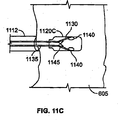
シード送達および脱離については、さまざまな他の実施形態が考えられる。例えば、図11Aは、遠位にあるバネ1105A、つまり「コークスクリュー」で心筋605内に固定されるシード1120Aを示している。送達カテーテル1112が備える送達ロッド1110は、ロッド1110を回して、バネを組織内に係合し、さらにネジ付き遠位ロッド部1115をシード1120Aから逆にねじって外すことによりシード1120Aから脱離される。図11Bでは、遠位にあるバネ1105Bは、シード1120Bの時計回り回転を使用して心筋605内にねじ込まれ、これはさらに、送達ロッドを逆にねじってシードから外す。送達ロッドを取り外した後、近位にあるバネ1125は、心筋605に曝される。時計回りバネ1105Bおよび反時計回りバネ1125は、一緒になって、シードが回転し、心筋内を平行移動することを防止する。バネを外す仕組みは、図に示されていない。送達ロッドおよびシードを通過する小さなプッシュロッドを使用して、遠位にあるバネをシードから押して、固定位置にすることが可能である。薄い鞘で、近位にあるバネ1125を覆うことが可能である。薄い鞘は、送達ロッドとともに引き込む。送達ロッドを脱離する他の手段は、ロッドの高抵抗部分のオーム加熱、および機械的剪断を含む。図11C〜Dでは、送達カテーテル1112の主管腔を通して用意されるプッシュロッド1135を使用して、尖叉1130が、シード1120Cの中心部から、溝1140を通して外に押し出され、心筋605内に入り、これにより、尖叉1130は、シード1120C本体から横方向に延び(図11Dに示されているように)、シード1120Cは、組織内に固定される。プッシュロッド1135は、取付け点のところで、尖叉1130の近位端接合点1145から取り外し可能である。プッシュロッド1135を近位端接合点1145から取り外す、つまり脱離するためにさまざまな機構が、図7の実施形態に関してすでに説明されているように、使用可能である。
Various other embodiments are contemplated for seed delivery and desorption. For example, FIG. 11A shows a
今度は図11E〜Kを参照すると、シード送達および脱離について考察されているいくつかの実施形態は、らせん状尖叉1105Eおよびシード1120Eを心筋605に固定する1つまたは複数の調節可能尖叉1110Eを備えるシード1120Eを含む。このような実施形態では、脱離機構1145Eおよび1165Eは、シード1120Eが心筋605に固定された後、細長いシャフト1160Eからシード1120Eを外すために使用することができる。
Referring now to FIGS. 11E-K, some embodiments discussed for seed delivery and detachment include one or more adjustable tines that fix the
図11Eを参照すると、シード1120Eは、シード送達カテーテル615の遠位部分内にあるように示されている。シード1120Eは、この実施例では、先端部1123Eが遠位端にある円筒型の本体1122Eを持つ。シード1120Eは、電気パルスを放出することができる2本の双極電極1135Eおよび1136Eを備えることができる。電極1135Eは、シード本体1122Eの遠位端に配置され、他の電極1136Eは、シード本体1122Eの近位端に配置される。この実施形態では、シード本体1122Eの先端部1123Eは、修正された円錐形状を有し、後の図で例示されるように、シード1120Eの遠位端を心筋壁605などの組織内に送達しやすくなっている。先端部1123Eは、先端部1123Eから延びる調節可能尖叉1110Eの張力のがし機構として使用することができる。さらに、先端部1123Eは、シード/心筋界面のところの線維性組織の形成を最小限に抑えるためにステロイド溶出を行わせることもできる。遠位および近位の電極1135Eおよび1136Eは、シード本体自体の上にあるように示されているが、他の場所も可能である。例えば、遠位電極1135Eは、電極間の分離距離が最大となるようにらせん状尖叉1105Eの末端に配置することができるか、または尖叉全体とすることもできる。他の実施例では、シード本体1122E上の先端部1123Eの表面は、遠位電極1135Eとして機能することもでき、これにより、シード本体1122Eが実質的に比較的小さなサイズの場合に、空間をより効率的に利用できる場合がある。さらに、先端部1123Eの表面を使用して遠位電極1135Eとして機能させることは、先端部1123Eのみが心内膜または心筋組織に接触する状況において望ましいと思われる(以下でさらに詳しく説明する)。
Referring to FIG. 11E, the
すでに説明されているように、シード送達カテーテル615は、その全長にわたって延びる主管腔712を持つ細長い管を含む。カテーテル615は、シード1120Eを送達カテーテル615の遠位端から解放できるように、その遠位端に開口部713を持つ。いくつかの状況では、シード1120Eの全部または一部は、シード1120Eが心臓組織に固定される前に送達カテーテル615から延びることができる。これらの場合には、主管腔712は、そのまま、細長いシャフトとスライドする形で係合するようにサイズを設定することができる。カテーテル615は、さらに、導電性リード716、および遠位開口部713の周りに延び、すでに説明されているような局所ECG情報を供給することができる電極625を備えることもできる。いくつかの実施形態では、シード配置の際にカテーテル615の先端を心臓組織に固定する必要がある場合もある。例えば、カテーテル615の遠位端は、カテーテル615を心臓組織に一時的に固定するためのネジ機構を備えることができる(図13に関して以下でさらに詳しく説明される)。
As previously described, the
この実施形態では、シード1120Eは、それぞれ共通接合部材1112Eから延びている複数の調節可能尖叉1110Eを持つ。図11Eに示されているように、調節可能尖叉1110Eはそれぞれに、一般的に、接合部材1112Eからシード本体1122Eの中心ボア1130Eを通って延びる。図11Eは、シード1120Eがまだ埋め込まれていない状態を示しており、らせん状尖叉1105Eのみが調節可能尖叉1110Eが中心ボア1130E内に配置されている間にシード本体1122Eから延びている。後でさらに詳しく説明されるが、接合部材1112Eは、作動ロッド1170Eにより遠位方向に押され、それにより、調節可能尖叉1110Eを中心ボア1130Eの遠位端から押しやることができる。制約された尖叉1110Eが中心ボア1130Eから延びる場合、尖叉1110Eは、渦巻き形状またはフック形状で延びるように偏倚される。接合部材1112Eは、中心ボア1130Eの直径よりも物理的に大きい場合があり、調節可能尖叉1110Eの作動のための停止点とすることができる。
In this embodiment, the
さらに図11Eを参照すると、細長いシャフト1160Eは、シード1120Eの脱離機構1145Eを係合/解放することができる脱離機構1165Eを遠位端に備える。この実施形態では、脱離機構1165Eは、シードの脱離機構1145E上の相補的ネジ付き部材と係合するネジ付き部材を備える。脱離機構1165Eと1145Eとの間のねじ山による係合は、シード1120Eがらせん状尖叉1105Eの回転により組織内に進んでゆくときにねじ山が外れないように配列することができる。
Still referring to FIG. 11E, the
脱離機構1165Eから、細長いシャフト1160Eは、引き続き送達カテーテル615を通して近位に入り、患者身体の外に出る(図11Eには示されていない)。細長いシャフト1160Eは患者身体の外側に延びることから、医師は、シード本体1122Eを(それに結合されている細長いシャフト1160Eを介して)導き送達カテーテル615の管腔712に通すことができる。(図11Iに関して以下でさらに詳しく説明されるように、送達カテーテル615は、アクセスカテーテルまたは他の操縦可能な鞘を通して埋め込み部位にナビゲートすることができる。アクセスカテーテルは、弁への外傷を減らし、複数のシードを心室壁内に埋め込みやすくすることができる、安定した弁交差を維持することができる。)細長いシャフト1160Eは、らせん状尖叉1105Eを心筋組織と係合させる目的として主管腔内で十分な剛性を保って回転できるような材質およびサイズ、ならびに設計で製作することができる。さらに、細長いシャフト1160Eは十分柔軟なものとし、細長いシャフト1160Eのナビゲーションおよびカテーテル615の埋め込み部位へのナビゲートを妨げないようにできる。
From the
作動ロッド1170Eは、細長いシャフト1160Eの管腔1162E内に配置することができる。差動ロッド1170Eは、接合部材1112Eと接触するように適合された係合表面1172Eを含む。係合表面1172Eから、作動ロッド1170Eは、細長いシャフト1160Eを通り近位へ移動し続け、患者身体の外に出ることができる。このような実施形態では、医師は、作動ロッド1170Eの近位端に力を加え、細長いシャフト1160E内でロッド1170Eをスライドさせることができる。細長いロッド1170Eのこのような動きにより、遠位の力を接合部材1112Eに加えることができる。作動ロッド1170Eは、接合部材1112Eに押し当てて、調節可能尖叉1110Eを強制的に中心ボア1130Eの遠位端から延ばせる十分な剛性を保つような材質、およびサイズのもので製作することができる。さらに、細長いロッド1170Eは、細長いシャフト1160Eの管腔1162E内に誘導して通せるように十分柔軟なものとすることができる。
The
次に図11F〜図11Hを参照すると、図11Eに示されているシード1120Eの少なくとも一部は、心筋605内に埋め込むことができる。図6に関してすでに説明されているように、送達カテーテル615は、心室(例えば、左心房32、左心室34、右心房36、または右心室38)内に誘導され、これにより、シード1120Eの少なくとも一部を心室から心筋605内に入れることができる。このような状況では、シードは、必ず、カテーテル615の遠位開口部713から、心臓壁の心地(例えば、心内膜606)を通り、心筋605内に入ることができる。図11F〜図11Hは、心筋605内に埋め込まれているシード1120Eを示しており、また心筋605にすでに固定されている隣接シード1120E(第1のシード1120Eの下の)も示している。
11F-11H, at least a portion of the
図11Fを参照すると、送達カテーテル615の管腔712内のシード1120Eは、細長いシャフト1160から力1167Eにより遠位端に向けて導くことができる。送達カテーテル615の遠位端は、シード1120Eが心臓壁の選択された部位に誘導されるように心室の内面に隣接する(または近い位置に配置される)ことができる。図11Eに示されているように、送達カテーテル615内のシード1120Eの調節可能尖叉1110Eは、中心ボア1130Eの遠位端から延びる作動位置にない(すでに埋め込まれている隣接シード1120Eの調節可能尖叉1110Eは、作動位置にあるように示されている)。らせん状尖叉1105Eは、以下でさらに詳しく説明されるように、心内膜606を貫通し、心筋605内に入るように構成される。
Referring to FIG. 11F, the
図11Gを参照すると、送達カテーテル615の管腔712内のシード1120Eは、細長いシャフト1160からねじり力1168Eにより回転されることができる。シード本体1122Eを長手方向軸に沿って回転させることにより、らせん状尖叉1105Eは、心臓壁内に「ねじ込む」ことができる。このような状況において、らせん状尖叉1105Eは、心内膜606を貫通し、心筋605内に入る。脱離機構1145Eがネジ付き部材を含むいくつかの実施形態では、細長いシャフト1160Eからのねじり力1168Eは、ネジによる係合を保持または締めるために使用することができる。
Referring to FIG. 11G, the
図11Gに示されている位置において、シードの調節可能尖叉1110Eは、中心ボア1130Eから延びていない(隣接するシードにより示されているとおり)。その結果、医師が、細長いシャフト1160Eを力1168Eの反対方向に回転させることによりこの位置からシード1110を引き戻すことがまだ可能であり、これにより、らせん状尖叉1105Eは、心筋組織から「逆にねじって外される」。シードの遠位電極1135Eは、心筋605と接触している。前述のように、シード1120Eは、送達カテーテル615上の電極625が選択された部位における電気的活動を監視している間に、ペーシング電気パルスを放出する指令を受け取ることができる。医師が、シード1120Eの現在の位置決めが満足のいくものではないと判断した場合、シード1120Eは、送達カテーテル管腔712内に引き込むことができ、次いで、他の位置に移動することができる。他の位置では、らせん状尖叉1105Eは、再び、心内膜を貫通し、心筋605内に入り、この場合、さらに電気的活動の監視を行うことができる。
In the position shown in FIG. 11G, the seed
図11Hを参照すると、シード1120Eが心臓壁に固定された後(例えば、らせん状尖叉1105Eの少なくとも一部およびおそらくはシード本体1122Eの一部が、心内膜内に貫通される)、また医師がシード1120Eの位置決めが適切であると判断した後、調節可能尖叉1110Eは、強制的に作動位置にすることができる。この実施形態では、細長いシャフト1160E内に配置されている作動ロッド1170Eは、接合部材1112E上に力を加えることができる。接合部材1112Eが強制的にシード本体1122Eへ向けられると、調節可能尖叉1110Eは、中心ボア1130Eの遠位端から延びる。この実施形態では、調節可能尖叉1110Eは、中心ボア1130Eにより制約されていない場合に渦巻き形状またはフック形状をとるように偏倚される。例えば、調節可能尖叉1110Eは、中心ボア1130E内で弾性的に変形された後、偏倚された形状に戻ることができる、ニチノールなどの形状記憶合金材料を含むことができる。調節可能尖叉1110Eは、心筋605内に埋め込まれ、補助的固定支持材となり、シード本体1122Eがさらに回転するのを実質的に阻止することができる。そのようなものとして、細長いシャフト1160Eは、シード本体1122Eに相対的に逆向きに回転され、これにより、脱離機構1165Eおよび1145Eのネジ付き部材は互いの係合を外す。この実施形態では、細長いシャフト1160Eは、シード1120Eを心筋605から引き抜くことなくシード本体1122Eに相対的に回転させることができるが、それは、らせん状尖叉1105Eが「逆にねじられて外される」のを調節可能尖叉1110Eが妨げるからである。シード1120Eが細長いシャフト1160Eから脱離された後、送達カテーテル615および細長いシャフト1160Eは、埋め込み部位から引き出されることができる。
Referring to FIG. 11H, after the
シード本体1122Eが心筋605内で実質的に回転するのを妨げるほかに、調節可能尖叉は、さらに、シード本体1122Eが心臓壁から引かれるか、または破られる可能性を小さくする。シード1120Eは、鼓動している心臓からのさまざまな力、および心室内の血液の乱流に曝されうる。いくつかの実施形態では、シード1120Eは、シード1120Eを心臓壁から取り外すのに必要なある閾値量の引張力が必要になるように、心臓壁に取り付けることができる。シード1120Eのいくつかの実施形態は、心臓壁からシード本体1122Eを取り外すのに必要な引張力が0.136kg(0.3lb)を超えるように心臓壁に固定することができる。いくつかの実施形態では、シード1120Eは、心臓壁からシード本体1122Eを取り外すのに必要な引張力が0.227kg(0.5lb)、好ましくは0.454kg(1.0lb)を超えるように心臓壁に固定することができる。
In addition to preventing the
一実施例では、らせん状尖叉1105Eおよび3つの調節可能尖叉1110Eを使用して、複数のシード1120Eがブタの心臓の心筋に固定された。ブタの心臓は、研究室に送られ、そこで、その一部が外科用メスで取り除かれ、心室内部が見えるようにされた。複数のシード1120Eは、心室内部からのブタ心臓壁に固定されたが、そのために、まず、らせん状尖叉1105Eを回転させて心筋内に入れ、次いで、実質的に心筋組織内にある渦巻き形状に合わせて調節可能尖叉1110Eを作動させた。シード1120Eはそれぞれ、心臓壁からシード本体1122Eを取り外すのに必要な引張力が0.136kg(0.3lb)、場合によっては0.454kg(1.0lb)を超えるように心臓壁に固定された。
In one example, a plurality of
次に図11Iを参照すると、らせん状尖叉1105Eおよび調節可能尖叉1110Eは、シード1120Eを心筋605に固定することができ、シード本体1122Eの少なくとも一部(例えば、先端部1123E)は心筋605内を貫通する。シード1120Eが心筋壁厚さよりも実質的に小さいいくつかの実施形態では、シード本体1122Eは、心筋組織内に完全に挿入されることができる。図11F〜図11Hに関して説明されている実施形態では、シード本体1122Eの遠位部分は、心筋605内に延び、その一方で、シード本体1122Eの近位部分は、心室(例えば、左心房32、左心室34、右心房36、または右心室38)に露出される。これらの図に示されているように、また図11Iに示されているように、シード本体1122Eは、遠位電極1135Eが心筋に接触し、その一方で、近位電極1136Eが心室(およびその中の血液)に曝されるように心筋605に固定することができる。いくつかの場合において、シード本体1122Eのこのような位置決めは、心筋壁の限られた厚さにより決められる。
Referring now to FIG. 11I, the
そのまま図11Iを参照すると、いくつかの場合において、シード本体1122Eは、心筋605内に完全には貫通できない。例えば、図11に示されている左心室34内に固定されている下側シード1120Eにより示されているように、シード1120Eの一部(例えば、らせん状尖叉1105Eおよび調節可能尖叉1110E)は、心内膜を貫通することができるが、シード本体1122Eの実質的部分は、心筋組織内に完全には貫通しない。このような状況では、先端部1123Eは、心内膜内に接触または貫通する(たぶん、部分的に心筋内に貫通する)ことができるが、シード本体1122Eの他の部分は、心臓壁内に貫通できない。しかしこの位置では、シード1120Eは、ペーシング電気パルスを近位心臓組織に与えることができる。ペーシング電気パルスの送出は、先端部1123Eの表面を使用して遠位電極1135Eとして機能させることにより容易にできる。
Still referring to FIG. 11I, in some cases, the
場合によっては、シード本体1122Eのこのような位置決めは、動作に関して利点を有する場合がある。例えば、遠位電極1135Eが一般に近くの組織細胞を脱分極するカソードである場合、また近位電極1136Eが近くの組織細胞を過分極化できるアノードである場合、図11F〜図11Iに示されているシード本体1122Eの位置によって、過分極化の効果が減じる可能性がある。この実施例では、アノードは、一般に、心室内の血液に曝されるため、心筋内の組織細胞は、必ずしもアノードにより過分極化されない。このような状況では、カソード、近くの心筋、心室内の近くの血液、およびアノードの間のペーシング電荷は、心筋組織内の局所領域の過分極化を減じる場合があり、ペーシングの有効性を制限する可能性のある一因である。
In some cases, such positioning of the
そのまま図11Iを参照すると、アクセスカテーテル675の遠位端676は、心室に誘導され、そこで、シード1120Eが送達される。アクセスカテーテル675は、近位端から遠位端676まで延びる管腔を備える。アクセスカテーテルは、さらに、心臓壁の近くにある選択された部位へ導かれるときに送達カテーテル615がスライドする形で通る遠位開口部を備える。いくつかの実施形態では、アクセスカテーテル675は、弁交差を確立し、保持するために使用することができる。このような状況では、送達カテーテル615は、第1のシード1120Eが正常に埋め込まれた後、患者体内から完全に引き出すことができるが、アクセスカテーテル675は、心室内のその位置を保持できる。次いで、新しい送達カテーテル615および細長いシャフト1160E(第2のシード1120Eが取り付けられている)は、アクセスカテーテル675に通して誘導され、心室内に入れられる。図11Iに示されているように、アクセスカテーテル675は、大動脈を通じて左心室34に接近することができる(例えば、大動脈弁を横切り、左心室34に入る)。標的とされる心室、患者の心臓血管内の状態、患者体内への進入点、および他の要因に応じて、他のアプローチも考えられる。例えば、アクセスカテーテル675は、下大静脈を通して、心房中隔内の穿刺を通じて、および左心室34に入る僧帽弁を通じて下へ、左心室34に接近することができる。
Still referring to FIG. 11I, the
すでに説明されているように、送達カテーテル615は、プッシュまたはプルワイヤなどの操縦機構を備え、心臓の壁の選択された部位に対しカテーテル615の遠位端を配置する作業を助けることができる。同様に、アクセスカテーテル675は、プッシュまたはプルワイヤなどの操縦機構を備え、選択された心室内の遠位端676の配置を助けることができる。この実施形態では、アクセスカテーテル675は、超音波プローブなどの画像装置685を、アクセスカテーテル675の遠位端676の近くに備える。画像装置685を使用することで、医師は心室内の埋め込み部位を視覚化することができる。心室の内面は、表面トポロジーも厚さもともに実質的にでこぼこしている可能性があるため、医師は、画像装置685を使用して、埋め込み部位を視覚化し、場合によってはその部位の心筋壁厚さを測定することができる。このような特徴は、活発に鼓動している心臓に手術を行う場合に特に有利であると考えられる。
As already described, the
次に、図11J〜図11Kを参照すると、シード1120Eの調節可能尖叉1110Eは、非作動位置(例えば、図11J)から作動位置(例えば、図11K)に強制的に移動することができる。すでに説明されているように、シード1120Eは、複数の調節可能尖叉1110Eを備えることができる。この実施形態では、シード1120Eは、それぞれ共通接合部材1112Eから延びている3つの調節可能尖叉1110Eを備える。図11Jに示されているように、調節可能尖叉1110Eが非作動位置にある場合、接合部材1112Eは、シード本体1122Eからオフセットされ、調節可能尖叉1110Eの少なくとも一部は、中心ボア1130E内で制約される。接合部材1112Eが、図11Kに示されているように、一般的にシード本体1122Eに向かう遠位方向に強制される場合、調節可能尖叉1110Eは、作動位置に移動される。すでに説明されているように、尖叉1110Eはそれぞれ、中心ボア1130Eから外された後、渦巻き形状またはフック形状で延びるように偏倚することができる。
11J-11K, the
次に図11L〜図11Nを参照すると、シードの他の実施形態は、シード本体の中心ボア内に配置されない調節可能尖叉を備えることができる。例えば、シード1120Lのいくつかの実施形態は、シード本体1122Lの周辺近くで縦方向に延びる非中心ボア1130L内に配置される複数の調節可能尖叉1110Lを備えることができる。シード1120Lの調節可能尖叉1110Lは、非作動位置(例えば、図11L)から作動位置(例えば、図11M)に強制的に移動することができる。この実施形態では、シード1120Lは、シード本体1122Lから遠位に延びるらせん状尖叉1105Lを備え、共通接合部材1112Lからそれぞれ延びる3つの調節可能尖叉1110Lを備える。図11Jに示されているように、調節可能尖叉1110Lが非作動位置にある場合、接合部材1112Lは、シード本体1122Lからオフセットされ、調節可能尖叉1110Lの少なくとも一部は、関連する中心ボア1130L内で制約される。接合部材1112Lが、図11Kに示されているように、一般的にシード本体1122Lに向かう遠位方向に強制される場合、調節可能尖叉1110Lは、作動位置に移動される。すでに説明されているように、尖叉1110Lはそれぞれ、中心ボア1130Lから外された後、渦巻き形状またはフック形状で延びるように偏倚することができる。尖叉1110Lは、さらに、電極1135Lなどを通じて、シード1120Lの側面から延びることができ、また、電極1135Lから組織内に励起信号を及ぼすように動作することも可能であろう。
Referring now to FIGS. 11L-11N, other embodiments of the seed can include adjustable tines that are not disposed within the central bore of the seed body. For example, some embodiments of the
図11Nを参照すると、シード1120Lのこの実施形態は、送達カテーテル615および細長いシャフト1160Lを使用して心臓壁の標的部位に導くことができる。細長いシャフト1160Lは、シード1120Lとの係合/係合解放を行う脱離機構1165Lを含むことができる。この実施形態では、脱離機構1165Lは、シードの脱離機構1145L上の相補的ネジ付き部材と係合するネジ付き部材を備える。すでに説明されているように、シード1120Lは、らせん状尖叉1105Lが心内膜606を貫通し、心筋605内に入るように回転させることができる。シード1120Lが適切に位置付けられている場合、作動ロッド1170Lからの力で、接合部材1112Lを、シード本体1122Lに向かう遠位方向に移動することができる。このような移動により、調節可能尖叉1110Lは、周辺ボア1130Lの遠位端から延び、それにより、調節可能尖叉1110Lおよびらせん状尖叉1105Lでシード1120Lを心筋605に固定する。調節可能尖叉1110Lが作動位置に移動された後、細長いシャフト1160Lは、脱離機構1145Lおよび1165Lでシード1120Lを解放するように回転され、これにより、送達カテーテル615および細長いシャフト1160Lを埋め込み部位から引き出すことができる。
Referring to FIG. 11N, this embodiment of
すでに説明されているように、シード本体は、尖叉、ネジ、釣り針、フック、または他の留め具を使用して心臓組織に固定することができる。図11P〜図11Uは、このような取付け機構の他の実施例を示している。図11Pを参照すると、シード1120Pのいくつかの実施形態は、本体ネジ1106Pおよび調節可能尖叉1110Pを備え、シード1120Pを心筋605に固定することができる。本体ネジ1106Pは、シード本体1122Pの回転で、シード本体1122Pの周りに巻き付けられたねじ山を備え、これにより心内膜606を貫通し心筋605に入るようにできる。ねじ山は、状況によっては、中断され、ねじられており、シード1120Pが組織から逆戻りしないように固定しやすくなっている。
As previously described, the seed body can be secured to the heart tissue using tines, screws, fishhooks, hooks, or other fasteners. 11P to 11U show another embodiment of such an attachment mechanism. Referring to FIG. 11P, some embodiments of the
調節可能尖叉1110Pは、接合部材1112Pがシード本体1122Pに向かう遠位方向に移動されたときに作動させることができる。図11Qを参照すると、シードのいくつかの実施形態は、単一の調節可能尖叉を備え、シードを心筋605に固定しやすくなっている。例えば、シード1120Qは、本体ネジ1106Q、および接合部材1112Qをシード本体1122Qの方へ移動させることにより作動される調節可能尖叉1110Qを備えることができる。
図11P〜図11Qの実施形態は、シード1120Pを組織内に進入させるのに役立つ場合がある。シード本体1122Pのテーパーがより大きく付いている端を用意し、本体ネジ1106Qをシード本体1122Pに接続することにより、シード1120Pは、シード本体1122Pが楽に組織内に入るための開口部を形成することができる。本体ネジ1106Qが使用されないいくつかの場合には、らせん状尖叉の遠位部分は、心臓壁組織内に入ることができるが、シード本体1122Pが組織に当たるとそれ以上先へ進むのを阻止することができる。また、ねじ山は図11P〜図11Qに、シード本体1122Pにきつく配置されているように示されているが、特にシード本体1122Pの前部テーパー付き部分の周りで、シード本体1122Pからわずかに離すことも可能であり、次いで、例えば、独りでに組織内に食い込むことができる薄いクモの巣状部により、シード本体1122Pに戻る形で接続することも可能である。シード本体が組織内に配置されることはすべての実施形態に必要なことではないが、組織の物理的構造を大きく破壊することなくシード本体1122が組織内に入ることができる他の適切な配列も使用することができる。
The embodiments of FIGS. 11P-11Q may help to penetrate
図11Rを参照すると、シードのいくつかの実施形態は、調節可能釣り針を備え、シードを心筋605に固定しやすくなっている。調節可能釣り針は、ボア内でもはや制約されなくなったときに外方向にシフトする偏倚された延長部を備えることができる。例えば、シード1120Rは、らせん状尖叉1105R内に移る本体ネジ1106R、および接合部材1112Rをシード本体1122Rの方へ移動させることにより作動される調節可能釣り針1111Rを備えることができる。図11Sを参照すると、シード1120Sのいくつかの実施形態は、らせん状尖叉1105Sおよび調節可能釣り針1111Sを備え、シード1120Sを心筋605に固定することができる。調節可能釣り針1111Sは、接合部材1112Sをシード本体1122Sの方へ移動することにより作動させることができる。図11Tを参照すると、シードのいくつかの実施形態は、1つまたは複数の本体釣り針1107Tを備え、シードを心筋605に固定しやすくなっている。本体釣り針1107Tは、シード本体1122Tから延びて、心筋605からの引き込みを防ぐフックとして働くことができる。例えば、シード1120Tは、心筋605内に完全に埋め込むことができ、本体釣り針1107T、および接合部材1112Tをシード本体1122Tの方へ移動させることにより作動させることができる調節可能尖叉1110Tを備えることができる。図11Uを参照すると、シード1120Uのいくつかの実施形態は、本体釣り針1107Uおよび調節可能釣り針1111Uを備え、シード1120Uを心筋605に固定することができる。調節可能釣り針1111Uは、接合部材1112Uをシード本体1122Uの方へ移動することにより作動させることができる。
Referring to FIG. 11R, some embodiments of the seed include an adjustable fishing hook to help secure the seed to the
次に図11V〜図11Wを参照すると、細長いシャフトとシードとの間の脱離機構のいくつかの実施形態は、係合位置(例えば、図11V)と係合解放位置(例えば、図11W)との間で移動可能な固定部材を備えることができる。このような実施形態では、細長いシャフトは、非円形の外側断面(正方形または六角形の断面外形)を有し、シード本体への回転運動の変換が楽に行える。 Referring now to FIGS. 11V-11W, some embodiments of the detachment mechanism between the elongate shaft and the seed are in an engaged position (eg, FIG. 11V) and an engaged release position (eg, FIG. 11W). And a fixing member movable between them. In such an embodiment, the elongate shaft has a non-circular outer cross-section (square or hexagonal cross-sectional profile) that facilitates conversion of rotational motion to the seed body.
図11Vを参照すると、シード1120Vは、前の実施形態で説明されているように、本体1122Vおよび電極1135Vおよび1136Vを備えることができる。さらに、シード1120Vは、すでに説明されているように尖叉、ネジ、釣り針、フック、または他の留め具(らせん状尖叉1105V、共通接合部材1112Vから延びる調節可能尖叉1110Vなど)を備えることができる。またはすでに説明されているように、シード1120Vは、細長いシャフト1160Vにより、送達カテーテル615の管腔712に通して誘導することができる。シード1120Vは、固定部材1166Vの少なくとも一部を受け入れる形状の空洞1146Vを持つ脱離機構1145Vを備えることができる。示されている実施形態では、空洞1146Vは、固定部材1166Vが空洞1146Vと係合する場合に、細長いシャフト1160がシード本体1122Vから引き込むことができないように小さな玉のような球状固定部材1166Vに合うように湾曲させることができる。
Referring to FIG. 11V, the
図11Wを参照すると、シード1120Vの少なくとも一部が心筋605内に適切に位置付けられる場合、力1177Vを作動ロッド1170Vから加え、接合部材1112Vをシード本体1122Vへ移動させることができる。接合部材1112Vのこのような移動により、調節可能尖叉1110Vは、シード本体1122Vから延び、これにより、シード1120Vを心筋605に固定することができる。さらに、作動ロッド1170Vの移動により、固定部材を係合解放位置に移動することができる。例えば、作動ロッド1170Vは、作動ロッド1170Vが尖叉1110Vを作動させるように接合部材1112Vを強制する場合に固定部材1166Vと実質的に揃う凹状表面1176Vを含むことができる。そのようなものとして、固定部材1166Vは、凹状表面1176Vの方へ移動し、空洞1146Vとの係合を外す。この係合解放により、シード1120Vの少なくとも一部が心筋605に固定されている状態で、作動ロッド1170V、細長いシャフト1160V、および送達カテーテル615をシード埋め込み部位から引き出すことができる。
Referring to FIG. 11W, when at least a portion of the
上述のもの以外の脱離機構も、適切な状況において使用することができる。例えば、上述のような複数の球状固定部材は、ハンダ付けなどによりワイヤの全長に沿って取り付けることができる。ワイヤは、カテーテルの先端に端と端を接して取り付けられる複数のシードの内部通路の下を通ることができる。それぞれの固定部材は、シードの内側の中心ボアから出て、シードの内面の対応する空洞に対し固定するように配置することができる。動作時に、また固定部材でそれぞれのシードを適所に保持しながら、最も遠位にあるシードを、シードを回転させることにより組織内に押し込むことができる。次いで、ワイヤを1つのシードの長さにわたって近位に引き出し、最も遠位になるシード内の固定部材が次に遠位にあるシードに引き戻され、他の固定部材がシード1つ分戻るようにすることができる。ワイヤをこのように制御しつつ引き出すには、例えば、外科医が取り扱うインデックス付きトリガ機構を使用する。次いで、第2のシード(最も遠位にあるシード)は、埋め込むことができ、ワイヤを再び引き出せる。このような方法で、複数のシードは、心室内への機構の単一導入から埋め込まれる。 Desorption mechanisms other than those described above can also be used in appropriate circumstances. For example, the plurality of spherical fixing members as described above can be attached along the entire length of the wire by soldering or the like. The wire can pass under a plurality of seed internal passages that are attached end-to-end to the tip of the catheter. Each securing member can be arranged to exit from the central bore inside the seed and to be secured to a corresponding cavity in the inner surface of the seed. In operation and while holding each seed in place with the securing member, the most distal seed can be pushed into the tissue by rotating the seed. The wire is then pulled proximally over the length of one seed, so that the fixation member in the most distal seed is then pulled back to the distal seed and the other fixation member is returned by one seed. can do. In order to pull out the wire in such a controlled manner, for example, an indexed trigger mechanism handled by a surgeon is used. The second seed (the most distal seed) can then be implanted and the wire can be withdrawn again. In this way, multiple seeds are implanted from a single introduction of the mechanism into the ventricle.
さらに、シードは、一次取付け機構が損傷したり、詰まったり、または他の何らかの形で使用不能になった場合などのために、取り外し用の代替え機構を備えることができる。例えば、近位の埋め込まれていない電極の周りに複数の溝を形成することができる。溝は、例えば、内向き延長部を持つ放射状に配列されたフィンガーを有するツールがそれらの延長部を電極の周りに配置できるように最初は浅く段々深くなってゆくようにできる。次いで、フィンガーの外側の周りで下にスライドするスリーブなどによりフィンガーを引き込め、延長部が溝の中に受け入れられるようにできる。次いで、ツールを回転させることで、延長部を溝の深い部分に入れることができ、シードを回転に係合させて、シードが組織から取り出せるようにできる。 In addition, the seed can include an alternative mechanism for removal, such as if the primary attachment mechanism is damaged, clogged, or otherwise becomes unusable. For example, multiple grooves can be formed around the proximal non-implanted electrode. The grooves can be initially shallow and progressively deeper, for example, so that tools having radially arranged fingers with inward extensions can place those extensions around the electrodes. The finger can then be retracted, such as by a sleeve that slides down around the outside of the finger, so that the extension is received in the groove. The tool can then be rotated to place the extension into the deep part of the groove and the seed can be engaged with the rotation so that the seed can be removed from the tissue.
図12は、横断する形の配置に加えて、またはそれに優先して、シード1220を心臓壁605に平行に配置できる可能性を示している。これは、例えば、瘢痕組織を含む心房または心室の領域内で、心臓壁が薄い場合に特に必要である。壁に平行に配置することは、壁厚さがシード長よりも小さい場合に特に必要である。カテーテル1212は、平行配置がしやすいように先端近くで湾曲させることができることに留意されたい。心臓壁605が心臓周期の間に移動しているため、シード配置の際にカテーテル1212の先端を心臓組織に固定する必要がある場合がある。この概念は、図13に例示されており、カテーテル1312を壁605に一時的に固定するコークスクリュー1350を示している。心臓内に貫通し、シード送出時にカテーテル先端を固定し安定化するためにカテーテルの遠位端から延びている尖叉も考えられる。尖叉は、シード配置の前に心臓壁内に延ばされ、シード配置の後、心臓壁から引き込められる。
FIG. 12 illustrates the possibility that the
図14Aおよび図14Bは、シードピックアップコイル1460がさらに遠位取付けとしての機能に使用され、心外膜空間1465内に延びるシード実施形態を示している。シードは、シード本体1402、遠位に延びるコイル1460、および近位尖叉1465を備える。コイル1460は、カテーテル1412が備える送達管1470内で下へ巻かれ、心外膜空間1465内に押し込められた後に、全直径まで膨張する。シードは、コイル1460を送達管1470内の遠位開口部から心外膜空間内に押し込むように動作するプッシュロッドまたはワイヤ1475を使用して押される。シード本体1402および近位尖叉は、心臓壁605内に残る。膨張したコイル1460は、直径が大きいためより多くの磁束を集められる、アンテナへの結合を高められる、ペーシングシステムの効率を高められるという利点を有する。図14A〜Bのシードは、比較的かさばるコイルを収めていないため、直径を小さくできる。シード本体1402は、図4の略図に示されているコンデンサおよび電子構成要素を収納している。近位尖叉1465は、追加固定のためシードに取り付けられているように示されている。
14A and 14B show a seed embodiment in which a
ここでもまた、近位電極と遠位電極との間の間隔を最大にし、不応性組織の最大体積を通じて伝導できるようにすることが望ましいことに留意されたい。例えば、図4の弾丸型シードは、線維性非不応性組織内に封じ込められるようにすることが可能であると思われる。この場合、線維性カプセルを囲む組織内の電流密度は、低すぎて、脱分極を引き起こせない。この問題の解決方法は、シードの最も遠い先端を電極として使用することである。例えば、尖叉715、720、750、および755(図7を参照)は、心外膜空間内に延びる電極として使用される好適な導電性材料でメッキすることができる。次いで、遠位尖叉と近位シード電極との間を通る電流は、不応性組織を通過する。さらに注意すべきこととして、近位尖叉750および755は、導電性材料でメッキすることが可能であり、近位電極710の延長部として使用されることである。遠位尖叉と近位尖叉との間を通る電流は、不応性組織に高確率で出会う。同様に、図14の心外膜コイルは、電気絶縁体により囲まれた中心導電コイルを含み、さらにこれは、導電性電極材料でコーティングされる。
Again, it should be noted that it is desirable to maximize the spacing between the proximal and distal electrodes so that they can conduct through the maximum volume of refractory tissue. For example, the bullet seed of FIG. 4 could be able to be contained within a fibrous non-refractory tissue. In this case, the current density in the tissue surrounding the fibrous capsule is too low to cause depolarization. The solution to this problem is to use the farthest tip of the seed as the electrode. For example,
完全を期すため、図15には、3つの直交するコイルが単一基板上に巻かれている他のシードコイル実施形態が示されている。基板は、透磁性材料から製作することができる。3つのコイルのそれぞれの中に誘導された電流は、整流され、単一のコンデンサに渡される。この実施形態では、送信アンテナに関するシードの向きは、重要でない。これが重要なのは、アンテナの平面に平行な軸を持つコイル間の結合がないからであり、アンテナの平面に垂直な軸でシードを埋め込むことは常に可能であるというわけではない。図15のシードは、3つの直交する方向のそれぞれで磁束を集め、最大磁束は、入射磁場の向きに関係なく集められる。 For completeness, FIG. 15 shows another seed coil embodiment in which three orthogonal coils are wound on a single substrate. The substrate can be made from a magnetically permeable material. The current induced in each of the three coils is rectified and passed to a single capacitor. In this embodiment, the seed orientation with respect to the transmit antenna is not important. This is important because there is no coupling between coils having an axis parallel to the plane of the antenna, and it is not always possible to embed the seed with an axis perpendicular to the plane of the antenna. The seed of FIG. 15 collects magnetic flux in each of three orthogonal directions, and the maximum magnetic flux is collected regardless of the direction of the incident magnetic field.
図4のシード回路内の電気的パラメータ、および図6のアンテナ260の幾何学的形状は、アンテナにより発生する磁場に対するシードの応答に関するコンピュータモデルを使用することにより最適化することができる。基本的要件は、充電が完了した後に図4のコンデンサ405に蓄積されるエネルギーが、シードの周りの組織に対するペーシング閾値エネルギーに等しいということである。例えば、従来のペースメーカー電極は、4マイクロジュール(E0=4μJ)のオーダーのエネルギーを送出し、心臓の鼓動毎に組織をペーシングする。この数値は、組織の種類、パルス形状、および電極幾何学的形状に依存するが、ここでは一実施例として使用される。次いで、N個の部位をペーシングするために必要な全エネルギーは、閾値エネルギーE0のN倍のオーダーである。例えば、10個のシードを使用して10個の部位がペーシングされる場合、全エネルギー要件は、心拍毎にNE0=40μJのオーダーである。心拍毎にアンテナ260により供給されなければならないエネルギーは、この最低ペーシングエネルギーに、アンテナからシードへのエネルギーの結合の全効率を掛けたものである。
The electrical parameters in the seed circuit of FIG. 4 and the geometry of the
充電時間τ内にそれぞれのシードに送出されるエネルギーは、所定のシード回路パラメータの集合、および注目しているシードの部位における時間に対する測定または計算された磁場について計算することができる。これは、コイル410内に誘導される電圧が、コイルをリンクする磁束の時間変化率に等しいことが知られているため可能である。所定のシードコンデンサに蓄積されるエネルギーを計算するのに必要な工程は以下のとおりである。
The energy delivered to each seed within the charging time τ can be calculated for a predetermined set of seed circuit parameters and a measured or calculated magnetic field against time at the site of the seed of interest. This is possible because the voltage induced in the
与えられたアンテナ形状、位置および向き、およびアンテナ電流波形I(t)について、
1)導電率および誘電率の現実的な周波数に依存する値を持つ組織媒質中にある、アンテナに関して所定の位置および所定の向きでシードコイル410をリンクする磁束を計算する。
2)コイル内に誘導される(およびコイル410と直列の電圧としてモデル化される)電圧を工程1)で計算された磁束の時間変化率として計算する。
3)スイッチ418を位置1にして、シード回路方程式を使用して、時間に対するコンデンサ405上の電荷、したがってコンデンサに蓄積されたエネルギー(405の容量を2倍した値で電荷の平方を除算した値に等しい)を計算する。
For a given antenna shape, position and orientation, and antenna current waveform I (t),
1) Calculate the magnetic flux that links the
2) Calculate the voltage induced in the coil (and modeled as a voltage in series with the coil 410) as the time rate of change of the magnetic flux calculated in step 1).
3) With
概して、磁場は、シードとアンテナとの間の分離距離が長くなるほど急速に低下する。これは、非常に大きなアンテナの場合には当てはまらない場合があるが、人体寸法がアンテナの実用的寸法を制限するシードの正確な配置(およびシードが3軸コイルを持たない場合の向き)は、アンテナの電流の大きさおよびそのシードを充電するのに要するON時間を決定する。次いで、アンテナからの最小の磁束をリンクするシードは、すべてのシードがペーシング用の閾値エネルギーを獲得することができなければならないため、これらのアンテナパラメータを決定する。このシードを「最弱リンク」と呼ぶことができ、単独で、最適なアンテナ電流波形および結合効率を計算するために使用される。 In general, the magnetic field decreases rapidly as the separation distance between the seed and the antenna increases. This may not be the case for very large antennas, but the exact placement of the seed (and the orientation when the seed does not have a triaxial coil) where the body dimensions limit the practical dimensions of the antenna is Determine the magnitude of the current in the antenna and the ON time required to charge its seed. The seed that links the minimum magnetic flux from the antenna then determines these antenna parameters because all seeds must be able to acquire threshold energy for pacing. This seed can be referred to as the “weakest link” and is used alone to calculate the optimal antenna current waveform and coupling efficiency.
エネルギー結合効率は、オン時間にアンテナにより失われるすべてのエネルギーの総和により割ったシードコンデンサに送られる全エネルギーNE0の割合として定義される。シミュレーションに入れることができるアンテナ損失は、以下のとおりである。 Energy coupling efficiency is defined as the fraction of total energy NE 0 sent to the seed capacitor divided by the sum of all energy lost by the antenna during the on-time. The antenna loss that can be included in the simulation is as follows.
・すべてのシードに送出されるエネルギー=NE0
・充電中にシード回路内で(オーム熱として)消費される電力
・充電中にアンテナ回路内で(オーム熱として)消費される電力
・導電性生体組織内に誘導される渦電流により(オーム熱として)消費される電力
-Energy sent to all seeds = NE 0
・ Power consumed in the seed circuit during charging (as ohmic heat) ・ Power consumed in the antenna circuit during charging (as ohmic heat) ・ Eddy current induced in conductive living tissue (ohmic heat) As consumed)
次いで、エネルギー結合効率は、NE0を、持続する充電時間にわたる上記の損失の総和で除算した値により与えられる。アンテナ回路内のオーム熱は、主に、アンテナ自体の中のI2R損失、およびアンテナ設計に含めることができる磁気材料中のヒステリシス損失によるものである。このことは、シード回路内のオーム加熱についても当てはまる。最弱リンクシードをペーシング閾値エネルギーまで充電するのに必要なアンテナ電流波形のパラメータが決定された後、これらの損失を計算することができる。アンテナ電流波形パラメータが決定された後、生体中のどれかの地点で発生する電場Eを計算することができる。次いで、アンテナの影響を受けるすべての身体部分の導電率がわかれば、身体の任意の地点における電流密度を、σをその地点における導電率として、J=σEと計算することができる。次いで、渦電流によるオーム加熱は、患者身体の体積について電力損失密度J・E=σ|E|2を積分することにより求められる。空間内の任意の地点におけるアンテナ波形により発生される磁場および電場は両方とも、磁気ベクトルポテンシャルから求められるため、以下の他の工程を使用して結合効率を計算することができる。 The energy coupling efficiency is then given by NE 0 divided by the sum of the above losses over a sustained charge time. The ohmic heat in the antenna circuit is mainly due to I 2 R losses in the antenna itself and hysteresis losses in the magnetic material that can be included in the antenna design. This is also true for ohmic heating in the seed circuit. Once the parameters of the antenna current waveform necessary to charge the weakest link seed to the pacing threshold energy are determined, these losses can be calculated. After the antenna current waveform parameter is determined, the electric field E generated at any point in the living body can be calculated. Then, if the conductivity of all body parts affected by the antenna is known, the current density at any point on the body can be calculated as J = σE, where σ is the conductivity at that point. The ohmic heating by eddy current is then determined by integrating the power loss density J · E = σ | E | 2 over the volume of the patient body. Since both the magnetic and electric fields generated by the antenna waveform at any point in space are determined from the magnetic vector potential, the following other steps can be used to calculate the coupling efficiency.
4)現実的な組織導電率および誘電率を使用して、シード媒質内の所定の電流波形から生じる、ベクトルポテンシャルAを計算する。
5)シードの部位における磁場をB=curl(A)で計算する
6)最弱リンクシードをペーシング閾値エネルギーまで充電するのに必要なアンテナ電流波形パラメータを5)から決定する
7)アンテナ回路損失を、6)で求められた電流波形について計算する
8)場に対するシードの配置および向きの与えられた集合が5)で計算されたとして、すべてのシード回路損失の総和を計算する
9)空間内の複数の地点における電場をE=−∂A/∂tで計算する
10)空間内の各点での導電率σに対する知られている、または推定された値を使用して患者身体全体にわたってσ|E|2を積分し、生体組織による吸収で失われるエネルギーを決定する
11)充電エネルギーに7)〜10)で計算された損失を加えた値で割ったシードに送出される充電エネルギーとして効率を計算する
シード設計、アンテナ設計、およびアンテナ回路波形の最適化は、工程1)〜11)を反復して実行され、結合効率の最大化が行われる。送信機の電池の寿命は、心拍毎にアンテナが結合効率で割った全ペーシングエネルギーNE0を供給しなければならないため、エネルギー結合効率から容易に計算される。電池に蓄積されている全エネルギーは、その体積にそのエネルギー密度を掛けたものである。次いで、システムがペーシングできる予想総心拍数は、全電池エネルギーにエネルギー結合効率を掛け心拍当たりのペーシングエネルギーNE0で割ったものである。平均心拍数、つまり毎分72拍を仮定すると、分単位の電池寿命が得られる。
4) Calculate the vector potential A resulting from the predetermined current waveform in the seed medium using realistic tissue conductivity and dielectric constant.
5) Calculate the magnetic field at the seed site with B = curl (A) 6) Determine the antenna current waveform parameter required to charge the weakest link seed to the pacing threshold energy from 5) 7) Antenna circuit loss 6) Calculate the current waveform obtained in 6) 8) Calculate the sum of all seed circuit losses assuming that the given set of seed placement and orientation relative to the field is calculated in 5) 9) In space Calculate the electric field at multiple points with E = −∂A / ∂t 10) Using the known or estimated value for the conductivity σ at each point in space, σ | E | 2 by integrating, Dispatched seeds divided by the calculated value obtained by adding a loss 7) to 10) to determine to 11) charges energy energy lost by absorption by body tissue Seed design to calculate the efficiency as a charging energy, antenna design, and optimization of antenna circuit waveforms, step 1) to 11) iteratively to be performed, maximizing coupling efficiency is performed. The battery life of the transmitter is easily calculated from the energy coupling efficiency because the antenna must supply the total pacing energy NE 0 divided by the coupling efficiency at every heartbeat. The total energy stored in the battery is its volume multiplied by its energy density. The expected total heart rate that the system can pace is then the total battery energy multiplied by the energy coupling efficiency and divided by the pacing energy NE 0 per heart beat. Assuming an average heart rate, ie 72 beats per minute, battery life in minutes is obtained.
一実施例の計算では、シードは、比誘電率が10に等しいコアに巻き付けた長さ3mm、直径2mmのコイルを備えていた。容量は、印加される磁場の周波数でコイルを共振させるように選択された。コイルのQ(共振ピークの幅で割った共振周波数)を10に等しくなるように選択することによりさらに制約を加えた。穏当なQの制約条件から、導電性組織による可能な周波数分散に対するマージン、および製造マージンが得られる。こうした仮定を置いて、コイルの軸に沿って向き付けられた磁場は、最小ペーシングエネルギー4μJを得るために約0.001テスラ(1mT)の大きさを持たなければならないことがわかった。この計算におけるアンテナモデルは、総重量100グラムの直径12.7cm(5インチ)の円形銅ループであった。使用される組織モデルは、導電率はほぼ同じである、心臓筋肉と血液を組み合わせたものであった。最弱リンクシードがアンテナの平面から7.62cm(3インチ)の距離のところに置かれた場合に、以下が決定された。最適なエネルギー結合は、効率が約0.5%でピークになる約30,000Hz(30kHz)の周波数で発生し、エネルギー密度720ジュール/グラムの100グラムの電池の寿命は、約2ヶ月であった。 In one example calculation, the seed comprised a 3 mm long and 2 mm diameter coil wound around a core having a relative dielectric constant equal to 10. The capacitance was selected to resonate the coil at the frequency of the applied magnetic field. Further constraints were added by selecting the coil Q (resonance frequency divided by the width of the resonance peak) to be equal to 10. The moderate Q constraint provides a margin for possible frequency dispersion by the conductive tissue and a manufacturing margin. With these assumptions, it has been found that the magnetic field directed along the axis of the coil must have a magnitude of approximately 0.001 Tesla (1 mT) to obtain a minimum pacing energy of 4 μJ. The antenna model in this calculation was a circular copper loop with a total weight of 100 grams and a diameter of 12.7 cm (5 inches). The tissue model used was a combination of heart muscle and blood, with approximately the same conductivity. The following was determined when the weakest link seed was placed at a distance of 3 inches from the plane of the antenna. Optimal energy coupling occurs at a frequency of about 30,000 Hz (30 kHz), where efficiency peaks at about 0.5%, and a 100 gram battery with an energy density of 720 joules / gram has a lifetime of about 2 months. It was.
効率は、シードとアンテナとの間の磁気結合を改善することにより改善することができる。これは、複数のアンテナ、例えば、心臓の前側の肋骨上で1つのループ、心臓の後側の肋骨上で1つのループを使用することにより実現できる。2つまたはそれ以上のアンテナループを使用すると、最弱リンクシードを上の実施例で使用された7.62cm(3インチ)よりもループに近くなるようにできる。アンテナループに対する他の場所は、心臓の右心室内に挿入され、通常の胸部埋め込み位置でペーシングされる制御装置に取り付けられるループとすることができる。このようなループは、特に、心臓が収縮するときの収縮期にアンテナが通電されるため、すべてのシードにより近い位置に置かれる。 Efficiency can be improved by improving the magnetic coupling between the seed and the antenna. This can be achieved by using multiple antennas, eg, one loop on the anterior rib of the heart and one loop on the posterior rib of the heart. If two or more antenna loops are used, the weakest link seed can be closer to the loop than the 3 inches used in the above example. Another location for the antenna loop can be a loop that is inserted into the right ventricle of the heart and attached to a controller that is paced at a normal chest implant location. Such a loop is placed closer to all seeds, especially because the antenna is energized during systole when the heart contracts.
電池寿命は、充電式電池を採用することにより無制限に延ばすことができる。電池は、アンテナ260への誘導結合により充電用のエネルギーを受け取ることができる。充電用の外部アンテナおよび送信機は、患者のベッドまたはイスの下もしくは周りに配置するか、または専用の衣服に組み込むことが可能である。充電式電池の代替えとして、図3のアンテナ、送信機、および電池を、衣類、または患者が着用する使い捨てパッチに組み込むことが可能である。シードペーシングを計時するために必要なECG信号は、右心房および右心室リードを有する従来のペースメーカーから誘導リンクを介して受信することが可能である。この場合、精緻なアンテナ設計を、専用衣類に組み込むことが可能である。例えば、アンテナは、心臓の許す範囲内で胸部を囲む部分を持つことが可能である。
Battery life can be extended indefinitely by employing rechargeable batteries. The battery can receive charging energy by inductive coupling to the
図16は、アンテナ260を通じて容量放電により供給される充電電流波形を持つアンテナ260、および電池1605により供給されるコンデンサ充電の略図を示している。コンデンサ1610について選択された値は、電流波形が単一ピークを持つか、または減衰正弦波形で電流リングがダウンするかどうかを決定する。通信用電子回路1615は、ペーシング放電信号をシードに送信するが、シードまたは従来のペースメーカーからECG信号を受信することもできる。充電用電子回路1620は、外部アンテナへの誘導リンクからアンテナを介してエネルギーを受け取り、電池を充電する。制御回路1625は、充電回路1620および通信用電子回路1615の動作を制御する。
FIG. 16 shows a schematic diagram of the
さらに、シード用の代替え電源も使用できることに留意されたい。例えば、鼓動する心臓の機械エネルギーは、シードをペーシングするのに必要なエネルギーよりも数桁大きい。シードの部位において、収縮期には心臓筋肉は厚くなり、心臓鼓に合わせて拡張期には薄くなる。心臓筋肉上に置かれた1mmの変換器は、心臓の収縮のため65μJのエネルギーを発生することが可能であり、これは、ペーシングに必要なエネルギーの10倍を超える。公称効率を有する単純な機械エネルギーから電気エネルギーへの変換器は、シードをペーシングするためのエネルギーを供給することが可能である。エネルギーの他の小型の局所源は、最近の文献で示唆されている。これらに含まれるのは、機械エネルギーを電気エネルギーに変換する圧電および電気活性高分子材料、生体熱および/または血流エネルギーを電気エネルギーに変換するバイオ電池、容易に遮蔽される短距離αまたはβ粒子を放出する少量の放射性物質である。 Furthermore, it should be noted that alternative power sources for seeds can be used. For example, the mechanical energy of the beating heart is several orders of magnitude greater than the energy required to pace the seed. At the seed site, the heart muscles become thicker during systole and thin during diastole to match the heartbeat. A 1 mm transducer placed on the heart muscle can generate 65 μJ of energy for heart contraction, which is more than 10 times the energy required for pacing. A simple mechanical to electrical energy converter with nominal efficiency can provide energy to pace the seed. Other small local sources of energy have been suggested in recent literature. These include piezoelectric and electroactive polymer materials that convert mechanical energy into electrical energy, biocells that convert biothermal and / or blood flow energy into electrical energy, easily shielded short-range α or β A small amount of radioactive material that emits particles.
それに加えて、図4のシード回路は、コンデンサおよび電圧制御スイッチを省くことにより簡素化することができる。つまり、シード回路は、組織と接触する電極間に接続されたコイルだけからなるようにできる。この場合、磁場パルスは、シードコイル内に電圧パルスを誘導し、誘導電圧は、直接、組織内に放電される。すべてのシードが同じであれば、すべてのシードのペーシングは同時である。しかし、誘導電圧の立ち上がり時間は、コイルパラメータの巻き数の調整、コア誘電率の調整、およびコイルと直列に接続される抵抗器の調整により調整することができる。そのため、立ち上がり時間の異なるシードの集合体は、シードの発射順序の同期を取るために使用することができる。制御装置は、単一の局所ECG、例えば、専用送信シード、またはデータを制御装置に送信する従来のペースメーカーの心房または右心室電極を感知することができる。次いで、アンテナ内への電流バーストは、それぞれの埋め込まれているシードの電気的特性により決定される正確な発射時間で、すべてのシードを発射させる。 In addition, the seed circuit of FIG. 4 can be simplified by omitting capacitors and voltage control switches. That is, the seed circuit can consist of only the coil connected between the electrodes in contact with the tissue. In this case, the magnetic field pulse induces a voltage pulse in the seed coil, and the induced voltage is discharged directly into the tissue. If all seeds are the same, all seed pacing is simultaneous. However, the rise time of the induced voltage can be adjusted by adjusting the number of turns of the coil parameter, adjusting the core dielectric constant, and adjusting a resistor connected in series with the coil. Therefore, a collection of seeds with different rise times can be used to synchronize the firing order of the seeds. The controller can sense a single local ECG, eg, a dedicated transmission seed, or a conventional pacemaker atrial or right ventricular electrode that transmits data to the controller. The current burst into the antenna then fires all seeds with an accurate firing time determined by the electrical characteristics of each embedded seed.
図18A〜図18Cは、心室の内側の心筋組織を含む、組織に刺激を送達するための簡素化されたシード1800の等価回路を示している端面図、側面図、および側面図である。図に示されているように、シードは、電池またはコンデンサなどのエネルギー蓄積構成要素を別に備えていない。代わりに、直径約1mm、長さ約3mmの円筒形とすることができるフェライトコア1805からなる。コア1805のそれぞれの端に、フェライトキャップ1810があり、これは、厚さ約1mm、直径約3mmの円板形態とすることができる。キャップ1810は、コア1805の末端に取り付けることができるか、コア1805を受け取る際に通る中心穴を備えることができるか、またはコア1805と一体形成することができる。リング電極1815は、それぞれのキャップの周囲に形成することができる。リング電極1815は、白金イリジウム合金などの適切な材料で形成することができる。リング電極1815は、医療グレードのエポキシ、シアノアクリレートなどを使用して、キャップ1810に接着することができる。電極および他の構成要素に対する他の配列も、使用することができ、構成要素の特定レイアウトおよび形状は、制限することではなく、例示することを目的として示されている。シードは、電池またはコンデンサなどの異なるエネルギー蓄積装置を持たないため、本明細書では、直接起動電極組立体または装置と呼ぶ。
18A-18C are end, side, and side views showing an equivalent circuit of a
シード1800は、コアの周りに巻かれたワイヤ1820の長いループを使用して信号を受信することができる。例えば、直径0.00508cm(0.002インチ)で、ポリウレタンナイロン絶縁体で覆われている99.99%の銀線を使用することができる。ワイヤ1820は、適切な方法でコア1805の周りに巻かれ、例えば、約900巻きの電線を含むことができる。一般に、コイル内に誘導される電圧は、電線の巻き数に比例する。直径の小さい電線は、電線がコア上の空体積を満たすときにより多くの巻き数となる(公称的に、外径3mm、内径1mmの長さ3mmのギャップ)。しかし、直径の小さい電線ほど、抵抗が高く、コイル抵抗がペーシングされる組織のインピーダンスに匹敵するようになる場合、組織に送られる正味エネルギーは減少する。一般に、電線の抵抗は、数百オームを超えてはならない。900巻きの電線1820の測定された抵抗は、約60オームである。
The
シード1800は、さらに、適宜カバーされ、シード1800内の材料を保護し、シード1800の周りの組織および体液から絶縁することができる。例えば、密封エポキシ層1830は、両方のキャップ1810の末端に塗布することができ、他の密封エポキシ層1825は、コイル線1820の外側の周りに塗布することができる。一般に、リング電極は、絶縁されないが、他の何らかの方法で処理することができ、シード1800の周りの組織に十分なエネルギーを送出することができる。コイル1105Eおよび/または尖叉1110Eの1つまたは複数、および/またはシード遠位湾曲面1123Eは、遠位電極1135Eの一部に電気的に接続することができる。それとは別に、1105E、1110E、および1123Eの1つまたは複数は、遠位電極としてリング1135Eの代わりに使用することができる。
The
一般に、シード1800は、9フレンチ送達カテーテルなどを通して、容易に送達できる十分な小ささでなければならない。このようなシードの例示的な寸法は、長さ5mm、直径3mmである。また、説明されたこのシードは、本明細書で先に説明されている送達および固定機構とともに組み込むことができる。シード1800に対する典型的なパラメータは、0.5ボルトよりも高い電圧パルス振幅(2ボルトが標準)、および約0.4ミリ秒のパルス持続時間である。それに加えて、電極の電荷を中和するために、シード1800が組織に送達する電気的波形は、一般に、反対極性の小さな振幅、長い持続時間のパルスが後に続く上述のペーシングパルス(遠位電極はカソードである)を持ち、時間についての波形の積分は0となる。
In general, the
都合のよいことに、説明されているシードは、極端に簡素化されており、したがって、1つまたは複数の特定の恩恵をもたらすことができる。第1に、単純な設計であるため、シードが取りうるフォームファクタは非常に小さい。小さなシードを使用すると、患者に与える組織外傷が少なくて済み、また例えば、上述のようにカテーテルの経皮経管的埋め込みを使用して、多くの場所に、容易に埋め込むことができる。このフォームファクタは、シード内で電気蓄積装置を使用するシステムに必要になるような、極端な小型化設計を行うことなく達成することができる。 Conveniently, the described seed is extremely simplified and can thus provide one or more specific benefits. First, because of the simple design, the form factor that the seed can take is very small. Using a small seed requires less tissue trauma to the patient and can be easily implanted in many locations using, for example, percutaneous transluminal implantation of a catheter as described above. This form factor can be achieved without the extreme miniaturization design required for systems that use electrical storage devices within the seed.
また単純な設計は、システムの部品が非常に少なく、磨耗したり、他の何らかの故障を起こすようなことも非常に少ないため、信頼性にも優れる可能性が高い。この単純な設計は、さらに、シードの製作がかなり単純で、そのため、安上がりであり、製造時の誤りも少ないため、製造性にも寄与する。それに加えて、説明されているアンテナ回路は、小さく、単純であり、埋め込みが簡単になり、コストが安くなり、同様の方法での製造性および信頼性が向上しうる。 Also, a simple design is likely to be highly reliable because it has very few system components and is very unlikely to wear out or cause some other failure. This simple design also contributes to manufacturability because the seed fabrication is fairly simple, so it is inexpensive and has few manufacturing errors. In addition, the described antenna circuit is small, simple, easy to embed, low cost, and can improve manufacturability and reliability in a similar manner.
この単純なシードは、さらに、運用の柔軟性もある。特に、ペーシング波形パラメータは、複数の埋め込まれている線無し電極のそれぞれと通信することなくアンテナ回路側で調節することができる。それに加えて、シードは、立ち上がり時間が極端に高速なものとすることができ(例えば、「瞬時ON」特性)、これにより、シード内の可能な電圧制限装置は、すべての電極に、ほぼ同じ立ち上がり時間で同じペーシングパルス振幅を与えることができる。 This simple seed also has operational flexibility. In particular, the pacing waveform parameters can be adjusted on the antenna circuit side without communicating with each of the plurality of embedded lineless electrodes. In addition, the seed can have an extremely fast rise time (eg, “instant on” characteristics), so that the possible voltage limiter in the seed is approximately the same for all electrodes. The same pacing pulse amplitude can be given at the rise time.
図18Cのシード1800に取り付けられている等価回路は、シード1800の周りの組織の特徴を表すように設計される。等価回路は、2つの並列インピーダンス1830、1835を含み、インピーダンス1830は抵抗器を持つ細胞外導電性流体を表し、インピーダンス1835は細胞内流体を表す抵抗器と直列の細胞容量による筋肉細胞インピーダンスを表す。等価回路は、候補線無し電極またはシード設計を検査し、特定の条件の下でどちらが最良の治療を行えるかを決定する際に有用である。等価回路は、さらに、シードを検査し、正常に動作していることを確認するために、設計段階の後、製造時に使用することもできる。例えば、製造されたシードは、埋め込まれたシステム内で使用されるのと実質的に同一の波形を持つ磁場内に置かれ、その反応を測定し、製造要件が満たされていることを確認することができる。この方法で、等価回路は、プロセスの2つの段階(設計および製造)において特に有用であると考えられる。
The equivalent circuit attached to the
シードの設計は、表面が時間変化磁場に垂直な面素の周囲に誘導される電圧に対する式から始めることにより数学的に表すことができる。 The seed design can be expressed mathematically by starting with an expression for the voltage induced around the surface element whose surface is perpendicular to the time-varying magnetic field.
Vind=−A(dB/dT) (1)
ただし、
Vind=誘導電圧(ボルト)
A=表面積(m2)
B=印加される磁場(テスラ)
V ind = −A (dB / dT) (1)
However,
V ind = induced voltage (volts)
A = surface area (m 2 )
B = Applied magnetic field (Tesla)
式(1)において、磁場は、表面の面積について空間内で一定していると仮定される。誘導電圧は、磁場の発生源の周囲の空間全体を通して存在する。電流は、時間変動磁場内に置かれている導電要素内に流れる。例えば、磁場の発生源は、上述のようにアンテナ内を流れる電流パルスとすることができる。外部磁場と位置を揃えたコイルでは、式(1)の電圧は、コイルのそれぞれの巻きにおいて誘導される。コイルが透磁性コア材料上に巻かれている場合、電圧は、コアの有効透磁率がさらに掛けられる。コイルが複数の層を持つ場合、式(1)の面積は、それぞれの連続する層についてさらに大きい。 In equation (1), the magnetic field is assumed to be constant in space for the surface area. The induced voltage exists throughout the space around the source of the magnetic field. Current flows in a conductive element that is placed in a time-varying magnetic field. For example, the source of the magnetic field can be a current pulse flowing through the antenna as described above. In a coil that is aligned with the external magnetic field, the voltage of equation (1) is induced at each turn of the coil. If the coil is wound on a permeable core material, the voltage is further multiplied by the effective permeability of the core. If the coil has multiple layers, the area of equation (1) is even greater for each successive layer.
これらの観察結果の下で、透磁性コア上に巻かれたコイル内に誘導される正味電圧は、以下のとおりである。 Under these observations, the net voltage induced in the coil wound on the permeable core is as follows:
Vind=−β(dB/dt) (2)
ただし、
β=μN(π/12)(Di 2+DiDo+Do 2)
μ=コアの有効透磁率(単位なし)
N=コイルの総巻き数
Di=コイルの内径(メートル)
Do=コイルの外径(メートル)
V ind = −β (dB / dt) (2)
However,
β = μN (π / 12) (D i 2 + D i D o + D o 2 )
μ = effective core permeability (no unit)
N = total number of turns of coil D i = inner diameter of coil (meter)
D o = coil outer diameter (meters)
磁場が、アンテナ内の電流パルスにより形成される場合、式(2)の誘導電圧の時間積分は0となるが、それは、磁場自体が、時刻0と、パルスが送出された後の両方において、0だからである。このようなシードは、時間に関する波形の積分が0となる上述の標準を満たす。
If the magnetic field is formed by a current pulse in the antenna, the time integral of the induced voltage in equation (2) is zero, which means that the magnetic field itself is both at
今度は円形ループアンテナにより発生する磁場の場合を考察するが、電流Iが流れる円形ループの中心から軸に沿って距離zのところにある磁場は、以下のとおりである。 Now consider the case of a magnetic field generated by a circular loop antenna. The magnetic field at a distance z along the axis from the center of the circular loop through which the current I flows is as follows.
B=(μ0NaI/D)[1+(2z/D)2]−3/2=γl (3)
ただし、
μ0=自由空間の透磁率=4π×10−7Weber/Amp−m
Na=アンテナの巻き線の数
D=アンテナ直径(メートル)
z=アンテナ中心からの軸に沿った距離(メートル)
γ=(μ0Na/D)[1+(2z/D)2]−3/2(テスラ/アンペア)
B = (μ 0 N a I / D) [1+ (2z / D) 2] -3/2 = γl (3)
However,
μ 0 = permeability of free space = 4π × 10 −7 Weber / Amp −m
N a = number of antenna windings D = antenna diameter (meters)
z = distance along the axis from the center of the antenna (meters)
γ = (μ 0 N a / D) [1+ (2z / D) 2 ] −3/2 (Tesla / Ampere)
アンテナを通る電流Iは、式(3)を式(2)内に挿入したときに時間微分により適切なペーシング波形が求められるパルスを発生することができる。図16に示されているような比較的単純な回路で、適切なパルスを発生させることができる。この図では、コンデンサ1610は、電池1605の電圧Vまで充電することができる。制御回路1625などのマイクロプロセッサ制御装置は、コンデンサ1610の近くにあるスイッチを動作させるように構成することができ、患者の心臓ECG内のp波を感知することができる。ECGは、例えば、制御装置埋め込みの部位近くで、または外部アンテナの場合には皮膚用パッチ電極を介して感知することができる。それとは別に、埋め込まれた感知リードまたは線無し電極は、ECG信号またはp波トリガを制御装置に送信することができる。図16の円形ループアンテナ間でコンデンサが切り替えられた場合、アンテナ内を流れる電流は、以下の式で与えられる。
The current I through the antenna can generate a pulse for which an appropriate pacing waveform is required by time differentiation when equation (3) is inserted into equation (2). Appropriate pulses can be generated with a relatively simple circuit as shown in FIG. In this figure,
I=(CVQ2/τS)[e−(1+S)t/(2τ)−e−(1−S)t/(2τ)] (4)
ただし、
C=容量(ファラッド)
V=印加される電圧(ボルト)
Q=線質係数(単位なし)=(1/R)(L/C)1/2
τ=L/R(時定数)(秒)
L=アンテナインダクタンス(ヘンリー)
R=アンテナおよびコンデンサの抵抗(オーム)
S=(1−[2Q]2)1/2
I = (CVQ 2 / τS) [e− (1 + S) t / (2τ) −e− (1−S) t / (2τ) ] (4)
However,
C = Capacity (Farad)
V = applied voltage (volts)
Q = quality factor (no unit) = (1 / R) (L / C) 1/2
τ = L / R (time constant) (seconds)
L = Antenna inductance (Henry)
R = antenna and capacitor resistance (ohms)
S = (1- [2Q] 2 ) 1/2
式(2)〜(4)を組み合わせると、線無し電極コイル内に誘導される電圧が得られる。 Combining equations (2)-(4) provides a voltage induced in the wireless electrode coil.
Vind=βγ(CVQ2/τ2S)[(1+S)e−(1+S)t/(2τ)−(1−S)e−(1−S)t/(2τ)] (5) V ind = βγ (CVQ 2 / τ 2 S) [(1 + S) e− (1 + S) t / (2τ) − (1−S) e− (1−S) t / (2τ) ] (5)
式(5)を数値評価することにより、波形は、Q>0.5のときに減衰正弦波形であり、Q<0.5のときにパルス波形であると判断できる。パルス波形は、ペーシングには適切であり、式(5)の数値評価により、パルスは、Q=0.5のときに最大の振幅を持つ。そのため、この理想化されたモデルでは、アンテナ構成要素は、Q=0.5となるように選択することができ、式(4)および(5)は(Q→0.5、S→0の極限において)以下のようになる。 By numerically evaluating Equation (5), it can be determined that the waveform is an attenuated sine waveform when Q> 0.5, and a pulse waveform when Q <0.5. The pulse waveform is appropriate for pacing, and according to the numerical evaluation of Equation (5), the pulse has the maximum amplitude when Q = 0.5. Therefore, in this idealized model, the antenna components can be selected such that Q = 0.5, and equations (4) and (5) are (Q → 0.5, S → 0 In the limit)
I=(CVt/4τ2)e−t/2τ (6)
Vind=βγ(CV/4τ2)(1−t/2τ)e−t/2τ (7)
I = (CVt / 4τ 2 ) e −t / 2τ (6)
V ind = βγ (CV / 4τ 2 ) (1−t / 2τ) e −t / 2τ (7)
式(7)の波形は、t=2tでゼロ交差するプラスのパルスを持ち、その後、浅いマイナスの波が時間に関して指数関数的に減少する。式(7)の波形は、上で望ましいものとして説明されているように、0まで積分する。0.4ミリ秒の所望のパルス幅について、τは、0.2ミリ秒と選択される。式(7)は、図19にプロットされ、時刻0における電圧は0.23ボルトとなっている。図の実線は、計算値を表しているが、三角形は、図18Aおよび18Bに示されているようなシードを使用する測定値を表している。特に、測定されたデータは、コア寸法が1mm、各端の末端フランジの厚さが1mmであるフェライトボビン上に巻かれたコイルを含む長さ5mmのシード電極本体で得られたもので、長さ3mm、内径1mm、外径3mmの電線のコイルは、0.00508cm(0.002インチ)の巻き数900巻きの絶縁銀線をフェライトボビンに巻いたものである。式(2)を使用すると、これらのパラメータから、値β=0.003m2が得られる。測定結果は、AWG#8銅線の4巻きで製作された直径17.78cm(7インチ)のアンテナを使用することで得た。
The waveform of equation (7) has a positive pulse that crosses zero at t = 2t, after which the shallow negative wave decreases exponentially with time. The waveform of equation (7) integrates to zero as described above as desirable. For a desired pulse width of 0.4 milliseconds, τ is selected as 0.2 milliseconds. Equation (7) is plotted in FIG. 19 and the voltage at
線無し電極は、円形アンテナの中心に置かれており、式(3)のパラメータから、γ=28×10−5テスラ/アンペアが得られる。アンテナ回路コンデンサは、C=0.02ファラッドであり、印加された電圧は、V=15ボルトであった。τ=0.2ミリ秒とすると、時刻0での電圧は、式(7)から計算され、これらのパラメータ値は、Vind=0.16ボルトであり、それに対し、図19の計算されたプロットではVind=0.23ボルトである。
The lineless electrode is placed at the center of the circular antenna, and γ = 28 × 10 −5 Tesla / ampere is obtained from the parameter of Equation (3). The antenna circuit capacitor was C = 0.02 Farad and the applied voltage was V = 15 volts. Assuming τ = 0.2 milliseconds, the voltage at
異なる厚さのエンドキャップを持つシードについてさらに試験を実施したが、コイルは1mmのフェライトコアに巻かれ、ギャップは巻かれた絶縁銀線で埋められた。誘導電圧が最高のシードは、厚さ1mmのエンドキャップを備え、それらの間の巻き線は3mmで、全直径は3mmであった。 Further tests were performed on seeds with different thickness end caps, but the coil was wound on a 1 mm ferrite core and the gap was filled with wound insulated silver wire. The seed with the highest induced voltage was equipped with a 1 mm thick end cap, the winding between them was 3 mm, and the total diameter was 3 mm.
このシードは、電極に取り付けられている図18Cの等価回路がある場合とない場合について試験された。図20は、上述の17.78cm(7インチ)円形ループアンテナの中心に置かれ、電圧はV=15ボルト、容量はC=0.02ファラッドのときのそのようなシード内に誘導される電圧のプロットを示している。図は、線無し電極が、組織インピーダンスにより著しく負荷低下せず、1ボルトを超えるペーシング電圧は、組織の存在下で容易に達成されることを示している。図の波形は、さらに、単純な小型線無し電極および単純なアンテナ回路を使用する心臓ペーシングにも適している。等価回路のない図20と図19とを比較すると、シードの有効透磁率は1.8/0.18=10であることがわかる(シードは同じ幾何学的形状および巻き数を持つため、ピーク誘導電圧の比に等しい)。 This seed was tested with and without the equivalent circuit of FIG. 18C attached to the electrode. FIG. 20 is centered on the above-mentioned 17.78 cm (7 inch) circular loop antenna, the voltage induced in such a seed when the voltage is V = 15 volts and the capacity is C = 0.02 Farad. The plot of is shown. The figure shows that the wireless electrode is not significantly unloaded by tissue impedance, and pacing voltages above 1 volt are easily achieved in the presence of tissue. The illustrated waveform is also suitable for cardiac pacing using simple miniature wireless electrodes and simple antenna circuitry. 20 and 19 without an equivalent circuit, it can be seen that the effective permeability of the seed is 1.8 / 0.18 = 10 (since the seed has the same geometric shape and number of turns, the peak Equal to the ratio of induced voltages).
ツェナーダイオードなどの受動電圧制限素子を、シードの刺激電極間に追加し、電圧パルス振幅を制御することができる。例えば、複数のシードがアンテナから複数の距離のところに配置される場合、印加される磁場の大きさは、式(3)に従って、シード毎に変わる。電圧制限素子は、制限電圧を発生するようにシードがアンテナに十分近い場合に、パルス振幅がすべてのシードおよびすべてのアンテナ構成について必ず同じになるようにすることができる。 A passive voltage limiting element such as a zener diode can be added between the seed stimulation electrodes to control the voltage pulse amplitude. For example, when multiple seeds are placed at multiple distances from the antenna, the magnitude of the applied magnetic field varies from seed to seed according to equation (3). The voltage limiting element can ensure that the pulse amplitude is the same for all seeds and all antenna configurations when the seed is close enough to the antenna to generate a limiting voltage.
本発明の多数の実施形態が説明された。しかしながら、本発明の範囲から逸脱することなくさまざまな修正を加えることができることは理解されるであろう。例えば、開示では、心臓組織に関して実施形態を説明しているが、本明細書で説明されているシステムおよび方法は、刺激して何らかの便益または結果を得ることができる他の細胞、組織、および器官の励起にも適用可能である。 A number of embodiments of the invention have been described. However, it will be understood that various modifications may be made without departing from the scope of the invention. For example, although the disclosure describes embodiments with respect to heart tissue, the systems and methods described herein are useful for other cells, tissues, and organs that can be stimulated to obtain some benefit or result. It can also be applied to excitation of.
いくつかの実施形態では、本明細書で説明されているシステムおよび方法は、ある種の神経学上の応用で使用することができる。例えば、線無し電極組立体および本明細書で説明されている関係するシステムは、痛みを制限し、筋肉の痙攣を制御し、発作を防止し、神経ホルモン疾患を治療するなどのために使用することができる。 In some embodiments, the systems and methods described herein can be used in certain neurological applications. For example, the wireless electrode assembly and related systems described herein are used to limit pain, control muscle spasms, prevent seizures, treat neurohormonal diseases, etc. be able to.
他の実施形態では、無リード電極組立体は、血管以外の他の導管を通して送達することができる。例えば、本明細書で説明されている線無し電極組立体は、食道を通して胃の内壁または消化管内の他の組織に送達することができる。電極組立体を使用して胃組織または消化管内の他の組織を電気的に刺激することにより、本明細書で説明されているシステムは、消化器疾患を治療するか、または空腹感を制御するために使用することができる。 In other embodiments, the leadless electrode assembly can be delivered through other conduits other than blood vessels. For example, the wireless electrode assembly described herein can be delivered through the esophagus to the stomach lining or other tissues in the gastrointestinal tract. By electrically stimulating stomach tissue or other tissues in the gastrointestinal tract using an electrode assembly, the system described herein treats digestive disorders or controls hunger Can be used for.
いくつかの実施形態では、本明細書で説明されている線無し電極組立体は、尿生殖路内に配置することができる。このような実施形態では、腹部内の器官組織は、腹膜腔を通じてカテーテルを介して経皮的にアクセスすることができる。 In some embodiments, the wireless electrode assembly described herein can be placed in the urogenital tract. In such embodiments, organ tissue within the abdomen can be accessed percutaneously through the catheter through the peritoneal cavity.
また、本明細書で説明されている、また組織の無リード刺激に関係する装置、システム、および方法は、他の種類のシードおよび/または関係する装置、システム、および方法の要素と組み合わせることができる。このような要素は、微小刺激装置とも呼ばれる、シード、およびそれぞれAdvanced Bionics Corporation社に譲渡され、それぞれ参照により本明細書に組み込まれている、同時係属の米国出願第10/607,963号、第10/609,449号、第11/034,190号、第11/043,642号、第10/607,962号、第11/043,404号、第10/609,452号、第10/609,457号、および第10/691,201号で説明されている装置、システム、および方法の関連する要素など、本明細書で説明されているもの以外とすることもできる。 Also, the devices, systems, and methods described herein and related to tissue-free lead stimulation may be combined with other types of seeds and / or elements of related devices, systems, and methods. it can. Such elements are also referred to as microstimulators, seeds, and co-pending US application Ser. No. 10 / 607,963, each assigned to Advanced Bionics Corporation, each incorporated herein by reference. No. 10 / 609,449, No. 11 / 034,190, No. 11 / 043,642, No. 10 / 607,962, No. 11 / 043,404, No. 10 / 609,452, No. 10 / It may be other than those described herein, such as the relevant elements of the devices, systems, and methods described in 609,457, and 10 / 691,201.
例えば、これらの出願で説明されている微小刺激装置は、シードとして使用することができ(適切な励起または刺激信号を送るように修正される)、本明細書で説明されている送達および取付けまたは固定機能を備えることができ、本明細書で説明されている装置および方法使用して埋め込むことができる。それとは別に、本明細書で説明されているようなシードに関係する装置、システム、および方法は、これらの組み込まれている出願において説明されている微小刺激装置に関係する装置、システム、および方法の少なくとも1つの要素を含むように修正することができる。このような少なくとも1つの要素は、埋め込みおよび/または外殖、定着および/または固定またはシードおよび/または微小刺激装置、シード、微小刺激装置、および他の埋め込まれたまたは外部電力分配および/またはデータ通信装置間の電力分配および/またはデータ通信、製造法、電子回路、密閉シードおよび/または微小刺激装置の機械的パッケージング、材料、および組み込まれているこれらの出願において説明されている装置、システム、および方法の他のすべての要素に関係しうる。 For example, the microstimulators described in these applications can be used as seeds (modified to deliver the appropriate excitation or stimulation signal), delivery and attachment described herein, or A fixation function can be provided and implanted using the apparatus and methods described herein. Alternatively, seed-related devices, systems, and methods as described herein are related to microstimulation devices described in these incorporated applications. Can be modified to include at least one element. Such at least one element may be implanted and / or explanted, settled and / or fixed or seeded and / or micro stimulator, seed, micro stimulator, and other implanted or external power distribution and / or data Power distribution and / or data communication between communication devices, manufacturing methods, electronic circuits, mechanical packaging of sealed seeds and / or micro stimulators, materials, and devices, systems described in these applications incorporated , And all other elements of the method.
Claims (7)
近位端と遠位端とを有するように構成されている経皮的な第2の血管内の細長い部材と、
前記第2の血管内の細長い部材の前記遠位端に機械的に結合するように構成されている無線電気刺激電極組立体と
を備えたシステムであって、
前記無線電気刺激電極組立体が前記第2の血管内の細長い部材に対して取り外し可能に機械的に結合されている場合に、前記第2の血管内の細長い部材および前記無線電気刺激電極組立体は、(1)前記管腔の中を通過することが可能な大きさおよび形状を有し、(2)前記無線電気刺激電極組立体の少なくとも一部を心内膜を通って心筋に経皮的に送達するように構成されており、
前記無線電気刺激電極組立体は、組織取付け機構を含み、前記組織取付け機構は、(1)心外膜壁を貫通することなく心内膜を貫通して心筋の中に入るように構成されている遠位に延びるらせん状尖叉と、(2)心外膜壁を貫通することなく心筋の中に入るように構成されている複数の放射状に延びる渦巻き状尖叉とを含む、システム。An elongate member in a percutaneous first blood vessel configured to have a proximal end and a distal end, the size and shape defining a lumen therethrough a first elongate member within the vessel and,
An elongate member in a percutaneous second blood vessel configured to have a proximal end and a distal end;
A wireless electrical stimulation electrode assembly configured to mechanically couple to the distal end of an elongate member in the second blood vessel ;
When the wireless electrostimulation electrode assembly removably is mechanically coupled to the elongated member of said second intravascular elongate member and the wireless electrostimulation electrode assembly of the second intravascular (1) has a size and shape that can pass through the said lumen, (2) through the myocardium I through the endocardium at least a portion of the wireless electrostimulation electrode assembly Configured to be delivered through the skin ,
The wireless electrical stimulation electrode assembly includes a tissue attachment mechanism that is configured to (1) penetrate the endocardium and enter the myocardium without penetrating the epicardial wall. And (2) a plurality of radially extending spiral tines configured to enter the myocardium without penetrating the epicardial wall .
Applications Claiming Priority (5)
| Application Number | Priority Date | Filing Date | Title |
|---|---|---|---|
| US10/971,550 | 2004-10-20 | ||
| US10/971,550 US7532933B2 (en) | 2004-10-20 | 2004-10-20 | Leadless cardiac stimulation systems |
| US11/075,376 | 2005-03-07 | ||
| US11/075,376 US7647109B2 (en) | 2004-10-20 | 2005-03-07 | Leadless cardiac stimulation systems |
| PCT/US2005/037979 WO2006045075A1 (en) | 2004-10-20 | 2005-10-19 | Leadless cardiac stimulation systems |
Publications (3)
| Publication Number | Publication Date |
|---|---|
| JP2008516741A JP2008516741A (en) | 2008-05-22 |
| JP2008516741A5 JP2008516741A5 (en) | 2008-12-04 |
| JP4891911B2 true JP4891911B2 (en) | 2012-03-07 |
Family
ID=35841939
Family Applications (2)
| Application Number | Title | Priority Date | Filing Date |
|---|---|---|---|
| JP2007538089A Expired - Fee Related JP4891911B2 (en) | 2004-10-20 | 2005-10-19 | Line-free cardiac stimulation system |
| JP2007538088A Expired - Fee Related JP4995090B2 (en) | 2004-10-20 | 2005-10-19 | Lead-free cardiac stimulation system |
Family Applications After (1)
| Application Number | Title | Priority Date | Filing Date |
|---|---|---|---|
| JP2007538088A Expired - Fee Related JP4995090B2 (en) | 2004-10-20 | 2005-10-19 | Lead-free cardiac stimulation system |
Country Status (5)
| Country | Link |
|---|---|
| US (7) | US7532933B2 (en) |
| EP (1) | EP1809372A2 (en) |
| JP (2) | JP4891911B2 (en) |
| CA (1) | CA2584648A1 (en) |
| WO (1) | WO2006045074A2 (en) |
Families Citing this family (291)
| Publication number | Priority date | Publication date | Assignee | Title |
|---|---|---|---|---|
| US20030036746A1 (en) | 2001-08-16 | 2003-02-20 | Avi Penner | Devices for intrabody delivery of molecules and systems and methods utilizing same |
| US7283874B2 (en) | 2000-10-16 | 2007-10-16 | Remon Medical Technologies Ltd. | Acoustically powered implantable stimulating device |
| US7024248B2 (en) * | 2000-10-16 | 2006-04-04 | Remon Medical Technologies Ltd | Systems and methods for communicating with implantable devices |
| US7198603B2 (en) * | 2003-04-14 | 2007-04-03 | Remon Medical Technologies, Inc. | Apparatus and methods using acoustic telemetry for intrabody communications |
| US6764446B2 (en) | 2000-10-16 | 2004-07-20 | Remon Medical Technologies Ltd | Implantable pressure sensors and methods for making and using them |
| US9308377B1 (en) * | 2000-12-15 | 2016-04-12 | Vortant Technologies, Llc | System and method for transmission of electrical signals in imperfectly-conducting media |
| US8301248B1 (en) | 2002-03-06 | 2012-10-30 | Boston Scientific Neuromodulation Corporation | Sequenced and simultaneous stimulation for treating congestive heart failure |
| AU2002952691A0 (en) | 2002-11-15 | 2002-11-28 | Sunshine Heart Company Pty Ltd | Heart assist device utilising aortic deformation |
| US8103358B2 (en) * | 2003-04-04 | 2012-01-24 | Medtronic, Inc. | Mapping guidelet |
| ES2561354T3 (en) | 2003-10-31 | 2016-02-25 | Sunshine Heart Company Pty Ltd | Synchronization control system |
| US9308382B2 (en) | 2004-06-10 | 2016-04-12 | Medtronic Urinary Solutions, Inc. | Implantable pulse generator systems and methods for providing functional and/or therapeutic stimulation of muscles and/or nerves and/or central nervous system tissue |
| US9205255B2 (en) | 2004-06-10 | 2015-12-08 | Medtronic Urinary Solutions, Inc. | Implantable pulse generator systems and methods for providing functional and/or therapeutic stimulation of muscles and/or nerves and/or central nervous system tissue |
| WO2005123181A2 (en) * | 2004-06-10 | 2005-12-29 | Ndi Medical, Llc | Implantable pulse generator for providing functional and/or therapeutic stimulation of muscles and/or nerves and/or central nervous system tissue |
| US20060064133A1 (en) | 2004-09-17 | 2006-03-23 | Cardiac Pacemakers, Inc. | System and method for deriving relative physiologic measurements using an external computing device |
| EP1812104B1 (en) | 2004-10-20 | 2012-11-21 | Boston Scientific Limited | Leadless cardiac stimulation systems |
| US7650186B2 (en) * | 2004-10-20 | 2010-01-19 | Boston Scientific Scimed, Inc. | Leadless cardiac stimulation systems |
| US7532933B2 (en) | 2004-10-20 | 2009-05-12 | Boston Scientific Scimed, Inc. | Leadless cardiac stimulation systems |
| US8175702B2 (en) | 2004-11-04 | 2012-05-08 | The Washington University | Method for low-voltage termination of cardiac arrhythmias by effectively unpinning anatomical reentries |
| US7813808B1 (en) | 2004-11-24 | 2010-10-12 | Remon Medical Technologies Ltd | Implanted sensor system with optimized operational and sensing parameters |
| US8818504B2 (en) * | 2004-12-16 | 2014-08-26 | Cardiac Pacemakers Inc | Leadless cardiac stimulation device employing distributed logic |
| US7558631B2 (en) * | 2004-12-21 | 2009-07-07 | Ebr Systems, Inc. | Leadless tissue stimulation systems and methods |
| EP1861160B1 (en) * | 2005-03-24 | 2011-11-16 | Metacure Limited | Wireless leads for gastrointestinal tract applications |
| US8391990B2 (en) | 2005-05-18 | 2013-03-05 | Cardiac Pacemakers, Inc. | Modular antitachyarrhythmia therapy system |
| AU2006262287A1 (en) | 2005-06-21 | 2007-01-04 | Cardiomems, Inc. | Method of manufacturing implantable wireless sensor for in vivo pressure measurement |
| US7742815B2 (en) | 2005-09-09 | 2010-06-22 | Cardiac Pacemakers, Inc. | Using implanted sensors for feedback control of implanted medical devices |
| US9168383B2 (en) | 2005-10-14 | 2015-10-27 | Pacesetter, Inc. | Leadless cardiac pacemaker with conducted communication |
| EP2471452B1 (en) * | 2005-10-14 | 2014-12-10 | Pacesetter, Inc. | Cardiac pacing system and method of conveying information therein |
| EP1957147B1 (en) * | 2005-12-09 | 2010-12-29 | Boston Scientific Scimed, Inc. | Cardiac stimulation system |
| US8050774B2 (en) | 2005-12-22 | 2011-11-01 | Boston Scientific Scimed, Inc. | Electrode apparatus, systems and methods |
| US8078278B2 (en) | 2006-01-10 | 2011-12-13 | Remon Medical Technologies Ltd. | Body attachable unit in wireless communication with implantable devices |
| US7937161B2 (en) * | 2006-03-31 | 2011-05-03 | Boston Scientific Scimed, Inc. | Cardiac stimulation electrodes, delivery devices, and implantation configurations |
| EP2029219B1 (en) * | 2006-05-17 | 2013-10-16 | Medtronic Urinary Solutions, Inc. | Implantable pulse generator systems |
| US9480846B2 (en) * | 2006-05-17 | 2016-11-01 | Medtronic Urinary Solutions, Inc. | Systems and methods for patient control of stimulation systems |
| US7955268B2 (en) | 2006-07-21 | 2011-06-07 | Cardiac Pacemakers, Inc. | Multiple sensor deployment |
| US7840281B2 (en) | 2006-07-21 | 2010-11-23 | Boston Scientific Scimed, Inc. | Delivery of cardiac stimulation devices |
| US8290600B2 (en) | 2006-07-21 | 2012-10-16 | Boston Scientific Scimed, Inc. | Electrical stimulation of body tissue using interconnected electrode assemblies |
| US7908334B2 (en) * | 2006-07-21 | 2011-03-15 | Cardiac Pacemakers, Inc. | System and method for addressing implantable devices |
| WO2008034005A2 (en) | 2006-09-13 | 2008-03-20 | Boston Scientific Scimed, Inc. | Cardiac stimulation using leadless electrode assemblies |
| US20080077184A1 (en) * | 2006-09-27 | 2008-03-27 | Stephen Denker | Intravascular Stimulation System With Wireless Power Supply |
| US20080088464A1 (en) * | 2006-09-29 | 2008-04-17 | Gutierrez Francisco M | Power System Architecture for Fluid Flow Measurement Systems |
| US8588904B2 (en) * | 2006-10-13 | 2013-11-19 | Lifescience Solutions Llc | Pacemaker |
| US7881806B2 (en) * | 2006-10-31 | 2011-02-01 | Medtronic, Inc. | Medical lead delivery device |
| US8532733B2 (en) * | 2006-10-31 | 2013-09-10 | Medtronic, Inc. | Mapping guidelet |
| WO2008078294A1 (en) * | 2006-12-22 | 2008-07-03 | Philips Intellectual Property & Standards Gmbh | Transmission line for use in magnetic resonance system |
| US8154389B2 (en) * | 2007-03-15 | 2012-04-10 | Endotronix, Inc. | Wireless sensor reader |
| US10003862B2 (en) | 2007-03-15 | 2018-06-19 | Endotronix, Inc. | Wireless sensor reader |
| EP2139556B1 (en) * | 2007-03-26 | 2014-04-23 | Remon Medical Technologies Ltd. | Biased acoustic switch for implantable medical device |
| US8644955B2 (en) * | 2007-03-30 | 2014-02-04 | Medtronic, Inc. | Controller for a medical lead delivery device |
| US8103359B2 (en) | 2007-05-17 | 2012-01-24 | Cardiac Pacemakers, Inc. | Systems and methods for fixating transvenously implanted medical devices |
| US8718773B2 (en) | 2007-05-23 | 2014-05-06 | Ebr Systems, Inc. | Optimizing energy transmission in a leadless tissue stimulation system |
| US20090035121A1 (en) * | 2007-07-31 | 2009-02-05 | Dresser, Inc. | Fluid Flow Modulation and Measurement |
| US8019419B1 (en) * | 2007-09-25 | 2011-09-13 | Dorin Panescu | Methods and apparatus for leadless, battery-less, wireless stimulation of tissue |
| US8209015B2 (en) * | 2007-10-09 | 2012-06-26 | Stealth Therapeutics, Inc. | Enhanced stability implantable medical device |
| US8874208B2 (en) | 2007-12-11 | 2014-10-28 | The Washington University | Methods and devices for three-stage ventricular therapy |
| US8560066B2 (en) | 2007-12-11 | 2013-10-15 | Washington University | Method and device for three-stage atrial cardioversion therapy |
| CN101939044B (en) * | 2007-12-11 | 2013-12-04 | 圣路易斯华盛顿大学 | Method and device for low-energy termination of atrial tachyarrhythmias |
| FR2924913B1 (en) * | 2007-12-18 | 2010-02-05 | Alain Telandro | SYSTEM FOR MEASURING OCULAR PRESSURE |
| US8041431B2 (en) * | 2008-01-07 | 2011-10-18 | Cardiac Pacemakers, Inc. | System and method for in situ trimming of oscillators in a pair of implantable medical devices |
| US8301262B2 (en) * | 2008-02-06 | 2012-10-30 | Cardiac Pacemakers, Inc. | Direct inductive/acoustic converter for implantable medical device |
| JP5153892B2 (en) * | 2008-02-07 | 2013-02-27 | カーディアック ペースメイカーズ, インコーポレイテッド | Wireless tissue electrical stimulation |
| JP5211177B2 (en) | 2008-02-11 | 2013-06-12 | カーディアック ペースメイカーズ, インコーポレイテッド | Hemodynamic monitoring method for rhythm discrimination in the heart |
| WO2009102640A1 (en) | 2008-02-12 | 2009-08-20 | Cardiac Pacemakers, Inc. | Systems and methods for controlling wireless signal transfers between ultrasound-enabled medical devices |
| WO2009120636A1 (en) * | 2008-03-25 | 2009-10-01 | Ebr Systems, Inc. | Temporary electrode connection for wireless pacing systems |
| US20090312650A1 (en) * | 2008-06-12 | 2009-12-17 | Cardiac Pacemakers, Inc. | Implantable pressure sensor with automatic measurement and storage capabilities |
| US8798761B2 (en) | 2008-06-27 | 2014-08-05 | Cardiac Pacemakers, Inc. | Systems and methods of monitoring the acoustic coupling of medical devices |
| WO2010011846A1 (en) * | 2008-07-23 | 2010-01-28 | St. Jude Medical, Inc. | Catheter radio frequency adapter for wireless communication |
| US20100191310A1 (en) * | 2008-07-29 | 2010-07-29 | Corventis, Inc. | Communication-Anchor Loop For Injectable Device |
| US8126566B2 (en) | 2008-08-14 | 2012-02-28 | Cardiac Pacemakers, Inc. | Performance assessment and adaptation of an acoustic communication link |
| US10695126B2 (en) | 2008-10-06 | 2020-06-30 | Santa Anna Tech Llc | Catheter with a double balloon structure to generate and apply a heated ablative zone to tissue |
| WO2010042291A1 (en) | 2008-10-10 | 2010-04-15 | Cardiac Pacemakers, Inc. | Systems and methods for determining cardiac output using pulmonary artery pressure measurements |
| US8593107B2 (en) * | 2008-10-27 | 2013-11-26 | Cardiac Pacemakers, Inc. | Methods and systems for recharging an implanted device by delivering a section of a charging device adjacent the implanted device within a body |
| WO2010059291A1 (en) | 2008-11-19 | 2010-05-27 | Cardiac Pacemakers, Inc. | Assessment of pulmonary vascular resistance via pulmonary artery pressure |
| US8527068B2 (en) | 2009-02-02 | 2013-09-03 | Nanostim, Inc. | Leadless cardiac pacemaker with secondary fixation capability |
| US9977100B2 (en) * | 2009-03-31 | 2018-05-22 | The University Of Queensland | Coil arrangement for use in a magnetic resonance imaging system |
| US8644927B2 (en) * | 2009-04-21 | 2014-02-04 | Incube Labs, Llc | Apparatus and method for the detection and treatment of atrial fibrillation |
| US8180456B2 (en) * | 2009-06-09 | 2012-05-15 | Pacesetter, Inc. | Systems and methods to configure a multi-electrode lead |
| US9409013B2 (en) * | 2009-10-20 | 2016-08-09 | Nyxoah SA | Method for controlling energy delivery as a function of degree of coupling |
| US8352028B2 (en) * | 2010-03-26 | 2013-01-08 | Medtronic, Inc. | Intravascular medical device |
| JP5918213B2 (en) | 2010-04-02 | 2016-05-18 | サンシャイン・ハート・カンパニー・ピーティーワイ・リミテッド | Composite cardiac assist system, method and apparatus |
| US8594806B2 (en) | 2010-04-30 | 2013-11-26 | Cyberonics, Inc. | Recharging and communication lead for an implantable device |
| WO2012004165A1 (en) * | 2010-07-08 | 2012-01-12 | Karolinska Institutet Innovations Ab | Novel endoluminal medical access device |
| US9610450B2 (en) | 2010-07-30 | 2017-04-04 | Medtronics, Inc. | Antenna for an implantable medical device |
| US9333365B2 (en) | 2010-07-30 | 2016-05-10 | Medtronic, Inc. | Antenna for an implantable medical device |
| EP2627403A4 (en) | 2010-10-12 | 2014-03-26 | Nanostim Inc | Temperature sensor for a leadless cardiac pacemaker |
| US9060692B2 (en) | 2010-10-12 | 2015-06-23 | Pacesetter, Inc. | Temperature sensor for a leadless cardiac pacemaker |
| US9020611B2 (en) | 2010-10-13 | 2015-04-28 | Pacesetter, Inc. | Leadless cardiac pacemaker with anti-unscrewing feature |
| US9457186B2 (en) | 2010-11-15 | 2016-10-04 | Bluewind Medical Ltd. | Bilateral feedback |
| WO2012082735A1 (en) | 2010-12-13 | 2012-06-21 | Nanostim, Inc. | Delivery catheter systems and methods |
| US9126032B2 (en) | 2010-12-13 | 2015-09-08 | Pacesetter, Inc. | Pacemaker retrieval systems and methods |
| EP2654889B1 (en) | 2010-12-20 | 2017-03-01 | Pacesetter, Inc. | Leadless pacemaker with radial fixation mechanism |
| MX340144B (en) | 2011-01-28 | 2016-06-15 | Stimwave Tech Inc | Neural stimulator system. |
| EP3586908A1 (en) | 2011-04-04 | 2020-01-01 | Micron Devices LLC | Implantable neural stimulator wireless lead |
| US9220897B2 (en) | 2011-04-04 | 2015-12-29 | Micron Devices Llc | Implantable lead |
| EP4356954A1 (en) | 2011-07-29 | 2024-04-24 | Curonix LLC | Remote control of power or polarity selection for a neural stimulator |
| US8758365B2 (en) | 2011-08-03 | 2014-06-24 | Medtronic, Inc. | Implant system including guiding accessory and methods of use |
| WO2013025632A1 (en) | 2011-08-12 | 2013-02-21 | Stimwave Technologies Incorporated | Microwave field stimulator |
| US9343224B2 (en) * | 2011-08-19 | 2016-05-17 | Leviticus Cardio Ltd. | Coplanar energy transfer |
| US9793579B2 (en) | 2013-11-08 | 2017-10-17 | Leviticus Cardio Ltd. | Batteries for use in implantable medical devices |
| US10543303B2 (en) | 2013-11-08 | 2020-01-28 | Leviticus Cardio Ltd. | Batteries for use in implantable medical devices |
| CA2848998A1 (en) | 2011-09-15 | 2013-03-21 | Stimwave Technologies Incorporated | Relay module for implant |
| US8945145B2 (en) | 2011-09-22 | 2015-02-03 | Medtronic, Inc. | Delivery system assemblies for implantable medical devices |
| US8945146B2 (en) * | 2011-10-24 | 2015-02-03 | Medtronic, Inc. | Delivery system assemblies and associated methods for implantable medical devices |
| US9017341B2 (en) * | 2011-10-31 | 2015-04-28 | Pacesetter, Inc. | Multi-piece dual-chamber leadless intra-cardiac medical device and method of implanting same |
| WO2013067496A2 (en) | 2011-11-04 | 2013-05-10 | Nanostim, Inc. | Leadless cardiac pacemaker with integral battery and redundant welds |
| US8721587B2 (en) * | 2011-11-17 | 2014-05-13 | Medtronic, Inc. | Delivery system assemblies and associated methods for implantable medical devices |
| US9216293B2 (en) | 2011-11-17 | 2015-12-22 | Medtronic, Inc. | Delivery system assemblies for implantable medical devices |
| US20140277231A1 (en) * | 2011-11-24 | 2014-09-18 | Laurent Berneman | Medical device involving muscle stimulation electrodes and an electromagnetic lead |
| US20150018728A1 (en) | 2012-01-26 | 2015-01-15 | Bluewind Medical Ltd. | Wireless neurostimulators |
| US9314399B2 (en) | 2012-03-06 | 2016-04-19 | Valencia Technologies Corporation | Implantable electroacupuncture system and method for treating dyslipidemia and obesity |
| US9327134B2 (en) * | 2012-03-12 | 2016-05-03 | Valencia Technologies Corporation | Implantable electroacupuncture device and method |
| EP2825251A4 (en) * | 2012-03-13 | 2015-02-25 | Sunshine Heart Co Pty Ltd | Methods, systems, and devices relating to wireless power transfer |
| GB2501077B (en) | 2012-04-10 | 2016-06-15 | Gloucestershire Hospitals Nhs Found Trust | Apparatus for artificial cardiac stimulation and method of using the same |
| WO2013177006A2 (en) | 2012-05-21 | 2013-11-28 | Stimwave Technologies, Incorporated | Methods and devices for modulating excitable tissue of the exiting spinal nerves |
| US9802054B2 (en) | 2012-08-01 | 2017-10-31 | Pacesetter, Inc. | Biostimulator circuit with flying cell |
| US9343923B2 (en) | 2012-08-23 | 2016-05-17 | Cyberonics, Inc. | Implantable medical device with backscatter signal based communication |
| EP3632303B1 (en) | 2012-09-14 | 2022-02-02 | Endotronix, Inc. | Pressure sensor, anchor, delivery system and method |
| US9935498B2 (en) | 2012-09-25 | 2018-04-03 | Cyberonics, Inc. | Communication efficiency with an implantable medical device using a circulator and a backscatter signal |
| US9861812B2 (en) | 2012-12-06 | 2018-01-09 | Blue Wind Medical Ltd. | Delivery of implantable neurostimulators |
| US8868178B2 (en) | 2012-12-11 | 2014-10-21 | Galvani, Ltd. | Arrhythmia electrotherapy device and method with provisions for mitigating patient discomfort |
| WO2014105973A1 (en) | 2012-12-26 | 2014-07-03 | Micron Devices, LLC | Wearable antenna assembly |
| KR20150143766A (en) * | 2013-04-15 | 2015-12-23 | 티앤더블유 엔지니어링 에이/에스 | Ecg monitor with an implantable part |
| US9592399B2 (en) | 2013-06-20 | 2017-03-14 | Cardiac Pacemakers, Inc. | Deployable multi-electrode leadless electrostimulator |
| US9333342B2 (en) | 2013-07-22 | 2016-05-10 | Cardiac Pacemakers, Inc. | System and methods for chronic fixation of medical devices |
| US10071243B2 (en) | 2013-07-31 | 2018-09-11 | Medtronic, Inc. | Fixation for implantable medical devices |
| EP3033141B1 (en) | 2013-08-16 | 2017-10-11 | Cardiac Pacemakers, Inc. | Leadless cardiac pacing devices |
| US9492674B2 (en) | 2013-08-16 | 2016-11-15 | Cardiac Pacemakers, Inc. | Leadless cardiac pacemaker with delivery and/or retrieval features |
| US9393427B2 (en) | 2013-08-16 | 2016-07-19 | Cardiac Pacemakers, Inc. | Leadless cardiac pacemaker with delivery and/or retrieval features |
| US10842993B2 (en) | 2013-08-16 | 2020-11-24 | Cardiac Pacemakers, Inc. | Leadless cardiac pacing devices |
| US10722723B2 (en) | 2013-08-16 | 2020-07-28 | Cardiac Pacemakers, Inc. | Delivery devices and methods for leadless cardiac devices |
| US9480850B2 (en) | 2013-08-16 | 2016-11-01 | Cardiac Pacemakers, Inc. | Leadless cardiac pacemaker and retrieval device |
| JP6182675B2 (en) | 2013-08-16 | 2017-08-16 | カーディアック ペースメイカーズ, インコーポレイテッド | Leadless cardiac pacemaker and collection device |
| ES2666373T3 (en) | 2013-08-16 | 2018-05-04 | Cardiac Pacemakers, Inc. | Management devices for wireless heart devices |
| JP6553623B2 (en) * | 2013-09-16 | 2019-07-31 | ザ ボード オブ トラスティーズ オブ ザ レランド スタンフォード ジュニア ユニバーシティー | Multi-element coupler for electromagnetic energy generation |
| GB2519302B (en) | 2013-10-15 | 2016-04-20 | Gloucestershire Hospitals Nhs Foundation Trust | Apparatus for artificial cardiac stimulation and method of using the same |
| US8831747B1 (en) | 2013-11-19 | 2014-09-09 | Pacesetter, Inc. | Leadless neurostimulation device and method including the same |
| EP3082953B1 (en) | 2013-12-20 | 2018-01-31 | Cardiac Pacemakers, Inc. | Leadless pacemaker with end-of-life protection |
| US9592391B2 (en) | 2014-01-10 | 2017-03-14 | Cardiac Pacemakers, Inc. | Systems and methods for detecting cardiac arrhythmias |
| WO2015106007A1 (en) | 2014-01-10 | 2015-07-16 | Cardiac Pacemakers, Inc. | Methods and systems for improved communication between medical devices |
| US10080887B2 (en) | 2014-04-29 | 2018-09-25 | Cardiac Pacemakers, Inc. | Leadless cardiac pacing devices including tissue engagement verification |
| WO2015168155A1 (en) | 2014-04-29 | 2015-11-05 | Cardiac Pacemakers, Inc. | Leadless cardiac pacemaker with retrieval features |
| CN106794339B (en) | 2014-05-12 | 2019-08-27 | 米克伦设备有限责任公司 | Remote RF power system with small size transmitting antenna |
| US9452293B2 (en) | 2014-06-19 | 2016-09-27 | Inspire Medical Systems, Inc. | Hybrid communication channel for communicating with an implantable medical device |
| US10390720B2 (en) | 2014-07-17 | 2019-08-27 | Medtronic, Inc. | Leadless pacing system including sensing extension |
| US9399140B2 (en) | 2014-07-25 | 2016-07-26 | Medtronic, Inc. | Atrial contraction detection by a ventricular leadless pacing device for atrio-synchronous ventricular pacing |
| US9694189B2 (en) | 2014-08-06 | 2017-07-04 | Cardiac Pacemakers, Inc. | Method and apparatus for communicating between medical devices |
| US9757570B2 (en) | 2014-08-06 | 2017-09-12 | Cardiac Pacemakers, Inc. | Communications in a medical device system |
| US9808631B2 (en) | 2014-08-06 | 2017-11-07 | Cardiac Pacemakers, Inc. | Communication between a plurality of medical devices using time delays between communication pulses to distinguish between symbols |
| US10478620B2 (en) | 2014-08-26 | 2019-11-19 | Medtronic, Inc. | Interventional medical systems, devices, and methods of use |
| US9526909B2 (en) | 2014-08-28 | 2016-12-27 | Cardiac Pacemakers, Inc. | Medical device with triggered blanking period |
| US9636505B2 (en) | 2014-11-24 | 2017-05-02 | AtaCor Medical, Inc. | Cardiac pacing sensing and control |
| EP3188793B1 (en) | 2014-09-04 | 2020-01-01 | Atacor Medical, Inc. | Receptacle for pacemaker lead |
| US10328268B2 (en) | 2014-09-04 | 2019-06-25 | AtaCor Medical, Inc. | Cardiac pacing |
| US10743960B2 (en) | 2014-09-04 | 2020-08-18 | AtaCor Medical, Inc. | Cardiac arrhythmia treatment devices and delivery |
| US10653859B2 (en) | 2014-10-07 | 2020-05-19 | Pacesetter, Inc. | Delivery catheter systems and methods |
| US9623234B2 (en) | 2014-11-11 | 2017-04-18 | Medtronic, Inc. | Leadless pacing device implantation |
| US9492669B2 (en) | 2014-11-11 | 2016-11-15 | Medtronic, Inc. | Mode switching by a ventricular leadless pacing device |
| US9492668B2 (en) | 2014-11-11 | 2016-11-15 | Medtronic, Inc. | Mode switching by a ventricular leadless pacing device |
| US9724519B2 (en) | 2014-11-11 | 2017-08-08 | Medtronic, Inc. | Ventricular leadless pacing device mode switching |
| US11097109B2 (en) | 2014-11-24 | 2021-08-24 | AtaCor Medical, Inc. | Cardiac pacing sensing and control |
| US10350417B2 (en) * | 2014-11-26 | 2019-07-16 | Medtronic, Inc. | Atrial synchronized ventricular pacing system using intracardiac pacemaker and extracardiac atrial sensing |
| US9289612B1 (en) | 2014-12-11 | 2016-03-22 | Medtronic Inc. | Coordination of ventricular pacing in a leadless pacing system |
| US10004896B2 (en) | 2015-01-21 | 2018-06-26 | Bluewind Medical Ltd. | Anchors and implant devices |
| WO2016126968A1 (en) | 2015-02-06 | 2016-08-11 | Cardiac Pacemakers, Inc. | Systems and methods for safe delivery of electrical stimulation therapy |
| EP3253450B1 (en) | 2015-02-06 | 2021-03-24 | Cardiac Pacemakers, Inc. | System for treating cardiac arrhythmias |
| US10046167B2 (en) | 2015-02-09 | 2018-08-14 | Cardiac Pacemakers, Inc. | Implantable medical device with radiopaque ID tag |
| CN107530002B (en) | 2015-03-04 | 2021-04-30 | 心脏起搏器股份公司 | System and method for treating cardiac arrhythmias |
| US10050700B2 (en) | 2015-03-18 | 2018-08-14 | Cardiac Pacemakers, Inc. | Communications in a medical device system with temporal optimization |
| WO2016149262A1 (en) | 2015-03-18 | 2016-09-22 | Cardiac Pacemakers, Inc. | Communications in a medical device system with link quality assessment |
| US10449354B2 (en) | 2015-04-23 | 2019-10-22 | Medtronics, Inc. | Intracardiac medical device |
| US9808618B2 (en) | 2015-04-23 | 2017-11-07 | Medtronic, Inc. | Dual chamber intracardiac medical device |
| US9757574B2 (en) | 2015-05-11 | 2017-09-12 | Rainbow Medical Ltd. | Dual chamber transvenous pacemaker |
| US9782589B2 (en) | 2015-06-10 | 2017-10-10 | Bluewind Medical Ltd. | Implantable electrostimulator for improving blood flow |
| CN108136187B (en) | 2015-08-20 | 2021-06-29 | 心脏起搏器股份公司 | System and method for communication between medical devices |
| US9853743B2 (en) | 2015-08-20 | 2017-12-26 | Cardiac Pacemakers, Inc. | Systems and methods for communication between medical devices |
| US9968787B2 (en) | 2015-08-27 | 2018-05-15 | Cardiac Pacemakers, Inc. | Spatial configuration of a motion sensor in an implantable medical device |
| US9956414B2 (en) | 2015-08-27 | 2018-05-01 | Cardiac Pacemakers, Inc. | Temporal configuration of a motion sensor in an implantable medical device |
| CN108136189B (en) | 2015-08-28 | 2021-10-15 | 心脏起搏器股份公司 | System for behavioral response signal detection and therapy delivery |
| US10226631B2 (en) | 2015-08-28 | 2019-03-12 | Cardiac Pacemakers, Inc. | Systems and methods for infarct detection |
| US10159842B2 (en) | 2015-08-28 | 2018-12-25 | Cardiac Pacemakers, Inc. | System and method for detecting tamponade |
| US10092760B2 (en) | 2015-09-11 | 2018-10-09 | Cardiac Pacemakers, Inc. | Arrhythmia detection and confirmation |
| CN108136185B (en) | 2015-10-08 | 2021-08-31 | 心脏起搏器股份公司 | Apparatus and method for adjusting pacing rate in an implantable medical device |
| US10105540B2 (en) | 2015-11-09 | 2018-10-23 | Bluewind Medical Ltd. | Optimization of application of current |
| US9713707B2 (en) | 2015-11-12 | 2017-07-25 | Bluewind Medical Ltd. | Inhibition of implant migration |
| WO2017106693A1 (en) | 2015-12-17 | 2017-06-22 | Cardiac Pacemakers, Inc. | Conducted communication in a medical device system |
| US10905886B2 (en) | 2015-12-28 | 2021-02-02 | Cardiac Pacemakers, Inc. | Implantable medical device for deployment across the atrioventricular septum |
| US10583303B2 (en) | 2016-01-19 | 2020-03-10 | Cardiac Pacemakers, Inc. | Devices and methods for wirelessly recharging a rechargeable battery of an implantable medical device |
| US10099050B2 (en) | 2016-01-21 | 2018-10-16 | Medtronic, Inc. | Interventional medical devices, device systems, and fixation components thereof |
| US10463853B2 (en) | 2016-01-21 | 2019-11-05 | Medtronic, Inc. | Interventional medical systems |
| WO2017136548A1 (en) | 2016-02-04 | 2017-08-10 | Cardiac Pacemakers, Inc. | Delivery system with force sensor for leadless cardiac device |
| US9731138B1 (en) | 2016-02-17 | 2017-08-15 | Medtronic, Inc. | System and method for cardiac pacing |
| JP6692920B2 (en) * | 2016-03-31 | 2020-05-13 | カーディアック ペースメイカーズ, インコーポレイテッド | Implantable medical device configured for deployment within a patient's heart chamber and implantable medical device configured for deployment within a patient's body |
| WO2017173275A1 (en) | 2016-03-31 | 2017-10-05 | Cardiac Pacemakers, Inc. | Implantable medical device with rechargeable battery |
| US9802055B2 (en) | 2016-04-04 | 2017-10-31 | Medtronic, Inc. | Ultrasound powered pulse delivery device |
| US10780280B2 (en) | 2016-04-26 | 2020-09-22 | Mayo Foundation For Medical Education And Research | Devices and methods for cardiac pacing and resynchronization |
| WO2019046205A1 (en) * | 2017-08-26 | 2019-03-07 | Macdonald, Stuart | Cardiac annuloplasty and pacing procedures, related devices and methods |
| US11039923B2 (en) | 2016-05-06 | 2021-06-22 | Transmural Systems Llc | Annuloplasty procedures, related devices and methods |
| US10328272B2 (en) | 2016-05-10 | 2019-06-25 | Cardiac Pacemakers, Inc. | Retrievability for implantable medical devices |
| US10668294B2 (en) | 2016-05-10 | 2020-06-02 | Cardiac Pacemakers, Inc. | Leadless cardiac pacemaker configured for over the wire delivery |
| US11331140B2 (en) | 2016-05-19 | 2022-05-17 | Aqua Heart, Inc. | Heated vapor ablation systems and methods for treating cardiac conditions |
| CN109414582B (en) | 2016-06-27 | 2022-10-28 | 心脏起搏器股份公司 | Cardiac therapy system for resynchronization pacing management using subcutaneous sensing of P-waves |
| US11207527B2 (en) | 2016-07-06 | 2021-12-28 | Cardiac Pacemakers, Inc. | Method and system for determining an atrial contraction timing fiducial in a leadless cardiac pacemaker system |
| WO2018009392A1 (en) | 2016-07-07 | 2018-01-11 | Cardiac Pacemakers, Inc. | Leadless pacemaker using pressure measurements for pacing capture verification |
| EP3487579B1 (en) | 2016-07-20 | 2020-11-25 | Cardiac Pacemakers, Inc. | System for utilizing an atrial contraction timing fiducial in a leadless cardiac pacemaker system |
| US20180042553A1 (en) * | 2016-08-10 | 2018-02-15 | Pacesetter, Inc. | Implantable Device with a Tail Extension Including Embedded Sensor and Antenna |
| CN109562269B (en) | 2016-08-19 | 2023-08-11 | 心脏起搏器股份公司 | Transseptal implantable medical device |
| US11071857B2 (en) | 2016-08-22 | 2021-07-27 | William Marsh Rice University | Systems and methods for wireless treatment of arrhythmias |
| EP3503799B1 (en) | 2016-08-24 | 2021-06-30 | Cardiac Pacemakers, Inc. | Integrated multi-device cardiac resynchronization therapy using p-wave to pace timing |
| EP3503970B1 (en) | 2016-08-24 | 2023-01-04 | Cardiac Pacemakers, Inc. | Cardiac resynchronization using fusion promotion for timing management |
| US10758737B2 (en) | 2016-09-21 | 2020-09-01 | Cardiac Pacemakers, Inc. | Using sensor data from an intracardially implanted medical device to influence operation of an extracardially implantable cardioverter |
| US10994145B2 (en) | 2016-09-21 | 2021-05-04 | Cardiac Pacemakers, Inc. | Implantable cardiac monitor |
| US10905889B2 (en) | 2016-09-21 | 2021-02-02 | Cardiac Pacemakers, Inc. | Leadless stimulation device with a housing that houses internal components of the leadless stimulation device and functions as the battery case and a terminal of an internal battery |
| WO2018081275A1 (en) | 2016-10-27 | 2018-05-03 | Cardiac Pacemakers, Inc. | Multi-device cardiac resynchronization therapy with timing enhancements |
| CN109890458B (en) | 2016-10-27 | 2023-08-11 | 心脏起搏器股份公司 | Implantable medical device with pressure sensor |
| EP3532159B1 (en) | 2016-10-27 | 2021-12-22 | Cardiac Pacemakers, Inc. | Implantable medical device delivery system with integrated sensor |
| US10434314B2 (en) | 2016-10-27 | 2019-10-08 | Cardiac Pacemakers, Inc. | Use of a separate device in managing the pace pulse energy of a cardiac pacemaker |
| US10561330B2 (en) | 2016-10-27 | 2020-02-18 | Cardiac Pacemakers, Inc. | Implantable medical device having a sense channel with performance adjustment |
| US10413733B2 (en) | 2016-10-27 | 2019-09-17 | Cardiac Pacemakers, Inc. | Implantable medical device with gyroscope |
| WO2018081344A2 (en) * | 2016-10-28 | 2018-05-03 | Covidien Lp | Electromagnetic navigation antenna assembly and electromagnetic navigation system including the same |
| JP6719024B2 (en) | 2016-10-31 | 2020-07-08 | カーディアック ペースメイカーズ, インコーポレイテッド | Implantable medical device for activity level pacing |
| JP6843235B2 (en) | 2016-10-31 | 2021-03-17 | カーディアック ペースメイカーズ, インコーポレイテッド | Systems and methods for activity level pacing |
| US10583301B2 (en) | 2016-11-08 | 2020-03-10 | Cardiac Pacemakers, Inc. | Implantable medical device for atrial deployment |
| WO2018089308A1 (en) | 2016-11-09 | 2018-05-17 | Cardiac Pacemakers, Inc. | Systems, devices, and methods for setting cardiac pacing pulse parameters for a cardiac pacing device |
| US10881869B2 (en) | 2016-11-21 | 2021-01-05 | Cardiac Pacemakers, Inc. | Wireless re-charge of an implantable medical device |
| CN109963618B (en) * | 2016-11-21 | 2023-07-04 | 心脏起搏器股份公司 | Leadless cardiac pacemaker with multi-mode communication |
| CN109996585B (en) | 2016-11-21 | 2023-06-13 | 心脏起搏器股份公司 | Implantable medical device with magnetically permeable housing and induction coil disposed around the housing |
| US10639486B2 (en) | 2016-11-21 | 2020-05-05 | Cardiac Pacemakers, Inc. | Implantable medical device with recharge coil |
| WO2018093605A1 (en) | 2016-11-21 | 2018-05-24 | Cardiac Pacemakers, Inc. | Leadless cardiac pacemaker providing cardiac resynchronization therapy |
| US10124178B2 (en) | 2016-11-23 | 2018-11-13 | Bluewind Medical Ltd. | Implant and delivery tool therefor |
| WO2018125791A1 (en) * | 2016-12-27 | 2018-07-05 | Cardiac Pacemakers, Inc. | Leadless delivery catheter with conductive pathway |
| US11207532B2 (en) | 2017-01-04 | 2021-12-28 | Cardiac Pacemakers, Inc. | Dynamic sensing updates using postural input in a multiple device cardiac rhythm management system |
| EP3573706A1 (en) | 2017-01-26 | 2019-12-04 | Cardiac Pacemakers, Inc. | Intra-body device communication with redundant message transmission |
| EP3573708B1 (en) | 2017-01-26 | 2021-03-10 | Cardiac Pacemakers, Inc. | Leadless implantable device with detachable fixation |
| US10029107B1 (en) | 2017-01-26 | 2018-07-24 | Cardiac Pacemakers, Inc. | Leadless device with overmolded components |
| US11615257B2 (en) | 2017-02-24 | 2023-03-28 | Endotronix, Inc. | Method for communicating with implant devices |
| CA3053497A1 (en) | 2017-02-24 | 2018-08-30 | Endotronix, Inc. | Wireless sensor reader assembly |
| WO2018175308A1 (en) * | 2017-03-20 | 2018-09-27 | Cardiac Pacemakers, Inc. | Leadless pacing device for treating cardiac arrhythmias |
| US10695572B2 (en) | 2017-04-03 | 2020-06-30 | Cardiac Pacemakers, Inc. | System for recharging a rechargeable implantable medical device including an implantable recharging bridge |
| US10821288B2 (en) | 2017-04-03 | 2020-11-03 | Cardiac Pacemakers, Inc. | Cardiac pacemaker with pacing pulse energy adjustment based on sensed heart rate |
| US10905872B2 (en) | 2017-04-03 | 2021-02-02 | Cardiac Pacemakers, Inc. | Implantable medical device with a movable electrode biased toward an extended position |
| AU2018254569B2 (en) | 2017-04-20 | 2022-05-12 | Endotronix, Inc. | Anchoring system for a catheter delivered device |
| US20180353764A1 (en) | 2017-06-13 | 2018-12-13 | Bluewind Medical Ltd. | Antenna configuration |
| DK3441111T3 (en) * | 2017-08-11 | 2020-10-26 | Oticon Medical As | IMPLANTABLE MEDICAL EQUIPMENT INCLUDING A WIRELESS TRANSCUTANE CONNECTION |
| WO2019036568A1 (en) | 2017-08-18 | 2019-02-21 | Cardiac Pacemakers, Inc. | Implantable medical device with a flux concentrator and a receiving coil disposed about the flux concentrator |
| CN111032148B (en) | 2017-08-18 | 2024-04-02 | 心脏起搏器股份公司 | Implantable medical device with pressure sensor |
| US11426578B2 (en) | 2017-09-15 | 2022-08-30 | Medtronic, Inc. | Electrodes for intra-cardiac pacemaker |
| US10758733B2 (en) | 2017-09-15 | 2020-09-01 | Medtronic, Inc. | Implantable medical device with retractable fixation sheath |
| CN111107899B (en) | 2017-09-20 | 2024-04-02 | 心脏起搏器股份公司 | Implantable medical device with multiple modes of operation |
| US11185703B2 (en) | 2017-11-07 | 2021-11-30 | Cardiac Pacemakers, Inc. | Leadless cardiac pacemaker for bundle of his pacing |
| US11071870B2 (en) | 2017-12-01 | 2021-07-27 | Cardiac Pacemakers, Inc. | Methods and systems for detecting atrial contraction timing fiducials and determining a cardiac interval from a ventricularly implanted leadless cardiac pacemaker |
| US11260216B2 (en) | 2017-12-01 | 2022-03-01 | Cardiac Pacemakers, Inc. | Methods and systems for detecting atrial contraction timing fiducials during ventricular filling from a ventricularly implanted leadless cardiac pacemaker |
| US11813463B2 (en) | 2017-12-01 | 2023-11-14 | Cardiac Pacemakers, Inc. | Leadless cardiac pacemaker with reversionary behavior |
| EP3717059A1 (en) | 2017-12-01 | 2020-10-07 | Cardiac Pacemakers, Inc. | Methods and systems for detecting atrial contraction timing fiducials within a search window from a ventricularly implanted leadless cardiac pacemaker |
| EP3735293B1 (en) | 2018-01-04 | 2022-03-09 | Cardiac Pacemakers, Inc. | Dual chamber pacing without beat-to-beat communication |
| US11529523B2 (en) | 2018-01-04 | 2022-12-20 | Cardiac Pacemakers, Inc. | Handheld bridge device for providing a communication bridge between an implanted medical device and a smartphone |
| CN108434600B (en) * | 2018-02-26 | 2021-11-02 | 郭成军 | Intracardiac implant, cardiac pacemaker, implant device |
| CN111787974A (en) | 2018-03-02 | 2020-10-16 | 美敦力公司 | Implantable medical-treatment electrode assemblies and devices |
| US11235159B2 (en) | 2018-03-23 | 2022-02-01 | Medtronic, Inc. | VFA cardiac resynchronization therapy |
| WO2019183514A1 (en) | 2018-03-23 | 2019-09-26 | Medtronic, Inc. | Vfa cardiac therapy for tachycardia |
| US11400296B2 (en) | 2018-03-23 | 2022-08-02 | Medtronic, Inc. | AV synchronous VfA cardiac therapy |
| CN108310652B (en) * | 2018-04-10 | 2021-09-28 | 创领心律管理医疗器械(上海)有限公司 | Heart implantation device and pacing system |
| US11179569B2 (en) | 2018-09-21 | 2021-11-23 | Cardiac Pacemakers, Inc. | Pacing method and system for cardioprotection during chemotherapy |
| JP2022501085A (en) | 2018-09-26 | 2022-01-06 | メドトロニック,インコーポレイテッド | Capturing in ventricular cardiac therapy from the atria |
| US11951313B2 (en) | 2018-11-17 | 2024-04-09 | Medtronic, Inc. | VFA delivery systems and methods |
| US11911625B2 (en) | 2018-11-20 | 2024-02-27 | The Regents Of The University Of California | Systems and methods for controlling wirelessly powered leadless pacemakers |
| US11679265B2 (en) | 2019-02-14 | 2023-06-20 | Medtronic, Inc. | Lead-in-lead systems and methods for cardiac therapy |
| US11759632B2 (en) | 2019-03-28 | 2023-09-19 | Medtronic, Inc. | Fixation components for implantable medical devices |
| US11697025B2 (en) | 2019-03-29 | 2023-07-11 | Medtronic, Inc. | Cardiac conduction system capture |
| US11213676B2 (en) | 2019-04-01 | 2022-01-04 | Medtronic, Inc. | Delivery systems for VfA cardiac therapy |
| CN109793989B (en) * | 2019-04-02 | 2021-08-13 | 创领心律管理医疗器械(上海)有限公司 | Leadless pacemaker and leadless pacemaker system |
| US11712188B2 (en) | 2019-05-07 | 2023-08-01 | Medtronic, Inc. | Posterior left bundle branch engagement |
| CA3141999A1 (en) | 2019-05-29 | 2020-12-03 | AtaCor Medical, Inc. | Implantable electrical leads and associated delivery systems |
| US11541232B2 (en) | 2019-06-18 | 2023-01-03 | Medtronic, Inc. | Electrode configuration for a medical device |
| US20220314008A1 (en) * | 2019-06-25 | 2022-10-06 | NeuSpera Medical Inc. | Wireless implantable device position validation in situ |
| US11524139B2 (en) | 2019-07-15 | 2022-12-13 | Medtronic, Inc. | Catheter with active return curve |
| US11524143B2 (en) | 2019-07-15 | 2022-12-13 | Medtronic, Inc. | Catheter with distal and proximal fixation members |
| US11684776B2 (en) | 2019-08-13 | 2023-06-27 | Medtronic, Inc. | Fixation component for multi-electrode implantable medical device |
| US11305127B2 (en) | 2019-08-26 | 2022-04-19 | Medtronic Inc. | VfA delivery and implant region detection |
| WO2021113486A1 (en) | 2019-12-03 | 2021-06-10 | Biovisics Medical, Inc. | Systems, implantable devices and methods for vision related stimulation |
| US11813466B2 (en) | 2020-01-27 | 2023-11-14 | Medtronic, Inc. | Atrioventricular nodal stimulation |
| WO2021174215A1 (en) | 2020-02-28 | 2021-09-02 | The Regents Of The University Of California | Integrated energy harvesting transceivers and transmitters with dual-antenna architecture for miniaturized implants and electrochemical sensors |
| US11975206B2 (en) | 2020-03-06 | 2024-05-07 | Medtronic, Inc. | Multi-electrode implantable medical device (IMD) |
| US11911168B2 (en) | 2020-04-03 | 2024-02-27 | Medtronic, Inc. | Cardiac conduction system therapy benefit determination |
| KR20210127836A (en) * | 2020-04-14 | 2021-10-25 | 삼성전자주식회사 | Wireless power receiver and object stimulator |
| US11666771B2 (en) | 2020-05-29 | 2023-06-06 | AtaCor Medical, Inc. | Implantable electrical leads and associated delivery systems |
| WO2021247490A1 (en) * | 2020-05-31 | 2021-12-09 | Maxwell Biomedical Inc. | Pacing and sensing devices and control system |
| US20220032071A1 (en) * | 2020-07-31 | 2022-02-03 | Medtronic, Inc. | Coronary sinus conduction system pacing and delivery |
| US11813464B2 (en) | 2020-07-31 | 2023-11-14 | Medtronic, Inc. | Cardiac conduction system evaluation |
| WO2023287859A1 (en) * | 2021-07-13 | 2023-01-19 | Maxwell Biomedical Inc. | Stimulation system |
| US11400299B1 (en) | 2021-09-14 | 2022-08-02 | Rainbow Medical Ltd. | Flexible antenna for stimulator |
| WO2024003649A1 (en) * | 2022-06-29 | 2024-01-04 | Cochlear Limited | Firmware independent reset |
| WO2024015555A1 (en) * | 2022-07-14 | 2024-01-18 | Maxwell Biomedical Inc. | Advanced pacing |
Citations (2)
| Publication number | Priority date | Publication date | Assignee | Title |
|---|---|---|---|---|
| JPH05245215A (en) * | 1992-03-03 | 1993-09-24 | Terumo Corp | Heart pace maker |
| US20020183791A1 (en) * | 2001-01-16 | 2002-12-05 | Stephen Denker | Implantable defibrillator with wireless vascular stent electrodes |
Family Cites Families (262)
| Publication number | Priority date | Publication date | Assignee | Title |
|---|---|---|---|---|
| US3057356A (en) | 1960-07-22 | 1962-10-09 | Wilson Greatbatch Inc | Medical cardiac pacemaker |
| US3357434A (en) | 1964-04-06 | 1967-12-12 | Avco Corp | Inductively linked receiver |
| US3667477A (en) | 1966-11-25 | 1972-06-06 | Canadian Patents Dev | Implantable vesical stimulator |
| US3596662A (en) | 1968-09-04 | 1971-08-03 | Medtronic Inc | Electrode for cardiac stimulator |
| US3713449A (en) | 1970-08-31 | 1973-01-30 | P Mulier | Cardiac pacer with externally controllable variable width output pulse |
| US3835864A (en) | 1970-09-21 | 1974-09-17 | Rasor Ass Inc | Intra-cardiac stimulator |
| US3943936A (en) | 1970-09-21 | 1976-03-16 | Rasor Associates, Inc. | Self powered pacers and stimulators |
| US3727616A (en) | 1971-06-15 | 1973-04-17 | Gen Dynamics Corp | Electronic system for the stimulation of biological systems |
| US3902501A (en) | 1973-06-21 | 1975-09-02 | Medtronic Inc | Endocardial electrode |
| US3942535A (en) * | 1973-09-27 | 1976-03-09 | G. D. Searle & Co. | Rechargeable tissue stimulating system |
| FR2300580A1 (en) * | 1975-02-14 | 1976-09-10 | Ethicon Inc | NEEDLE SURGICAL ELECTRODES IMPROVEMENT |
| SE7610696L (en) | 1976-09-28 | 1978-03-29 | Reenstierna Bertil | KIT AND DEVICE FOR INSERTING AND FIXING "PACEMAKER - ELECTROD" IN (HUMAN) HEART |
| US4256115A (en) | 1976-12-20 | 1981-03-17 | American Technology, Inc. | Leadless cardiac pacer |
| US4157720A (en) | 1977-09-16 | 1979-06-12 | Greatbatch W | Cardiac pacemaker |
| US4198991A (en) | 1978-05-17 | 1980-04-22 | Cordis Corporation | Cardiac pacer lead |
| US4721118A (en) | 1981-04-20 | 1988-01-26 | Cordis Leads, Inc. | Pervenous electrical pacing lead with foldable fins |
| US4441210A (en) | 1981-09-18 | 1984-04-03 | Hochmair Erwin S | Transcutaneous signal transmission system and methods |
| JPS5889075A (en) | 1981-11-24 | 1983-05-27 | Hitachi Ltd | Resonance type switching power source |
| US4543955A (en) | 1983-08-01 | 1985-10-01 | Cordis Corporation | System for controlling body implantable action device |
| DE3414072A1 (en) | 1984-04-13 | 1985-10-17 | Siemens AG, 1000 Berlin und 8000 München | ENDOCARDIAL ELECTRODE ARRANGEMENT |
| JPS61148261A (en) | 1984-12-21 | 1986-07-05 | Toray Ind Inc | Polyester resin composition |
| JPS61203730A (en) | 1985-03-07 | 1986-09-09 | Yanase & Assoc:Kk | Radio receiver |
| US4681111A (en) | 1985-04-05 | 1987-07-21 | Siemens-Pacesetter, Inc. | Analog and digital telemetry system for an implantable device |
| US4644957A (en) * | 1985-04-08 | 1987-02-24 | Ricciardelli Robert H | Applicator structure for biological needle probes employing spiral-shaped retaining coils |
| US4654664A (en) * | 1985-05-20 | 1987-03-31 | Rockwell International Corporation | Electronic null-seeking goniometer for ADF |
| US4860750A (en) * | 1986-04-17 | 1989-08-29 | Intermedics Inc. | Sidelock pacer lead connector |
| US4830006B1 (en) | 1986-06-17 | 1997-10-28 | Intermedics Inc | Implantable cardiac stimulator for detection and treatment of ventricular arrhythmias |
| IT1214738B (en) | 1986-11-11 | 1990-01-18 | Sbm Soc Brevetti Medicina | IMPROVEMENT IN CARDIAC STIMULATION SYSTEMS VIA PACEMAKER |
| US4858623A (en) | 1987-07-13 | 1989-08-22 | Intermedics, Inc. | Active fixation mechanism for lead assembly of an implantable cardiac stimulator |
| JPH02307481A (en) | 1989-05-08 | 1990-12-20 | Intermedics Inc | Positive fixing mechanism for lead assembly of buried cardiotonic device |
| US4953564A (en) | 1989-08-23 | 1990-09-04 | Medtronic, Inc. | Screw-in drug eluting lead |
| US4987897A (en) | 1989-09-18 | 1991-01-29 | Medtronic, Inc. | Body bus medical device communication system |
| US5143090A (en) | 1989-11-02 | 1992-09-01 | Possis Medical, Inc. | Cardiac lead |
| US5255693A (en) | 1989-11-02 | 1993-10-26 | Possis Medical, Inc. | Cardiac lead |
| US5178149A (en) | 1989-11-06 | 1993-01-12 | Michael Imburgia | Transesophageal probe having simultaneous pacing and echocardiographic capability, and method of diagnosing heart disease using same |
| US5314458A (en) * | 1990-06-01 | 1994-05-24 | University Of Michigan | Single channel microstimulator |
| US5113869A (en) * | 1990-08-21 | 1992-05-19 | Telectronics Pacing Systems, Inc. | Implantable ambulatory electrocardiogram monitor |
| US5170802A (en) | 1991-01-07 | 1992-12-15 | Medtronic, Inc. | Implantable electrode for location within a blood vessel |
| US5139033A (en) | 1991-03-04 | 1992-08-18 | Cardiac Pacemakers, Inc. | Sutureless myocardial lead implantation device |
| US5383915A (en) | 1991-04-10 | 1995-01-24 | Angeion Corporation | Wireless programmer/repeater system for an implanted medical device |
| US5674259A (en) | 1992-10-20 | 1997-10-07 | Gray; Noel Desmond | Multi-focal leadless apical cardiac pacemaker |
| US6144879A (en) | 1991-05-17 | 2000-11-07 | Gray; Noel Desmond | Heart pacemaker |
| US6044300A (en) * | 1991-05-17 | 2000-03-28 | Gray; Noel Desmond | Heart pacemaker |
| US5954757A (en) | 1991-05-17 | 1999-09-21 | Gray; Noel Desmond | Heart pacemaker |
| US5243977A (en) | 1991-06-26 | 1993-09-14 | Trabucco Hector O | Pacemaker |
| US5324325A (en) | 1991-06-27 | 1994-06-28 | Siemens Pacesetter, Inc. | Myocardial steroid releasing lead |
| US5335664A (en) | 1991-09-17 | 1994-08-09 | Casio Computer Co., Ltd. | Monitor system and biological signal transmitter therefor |
| JPH0576501A (en) | 1991-09-17 | 1993-03-30 | Casio Comput Co Ltd | Monitoring system and portable electronic equipment used for monitoring system |
| US5246014A (en) | 1991-11-08 | 1993-09-21 | Medtronic, Inc. | Implantable lead system |
| US5312439A (en) | 1991-12-12 | 1994-05-17 | Loeb Gerald E | Implantable device having an electrolytic storage electrode |
| US5234437A (en) | 1991-12-12 | 1993-08-10 | Target Therapeutics, Inc. | Detachable pusher-vasoocclusion coil assembly with threaded coupling |
| US5261916A (en) | 1991-12-12 | 1993-11-16 | Target Therapeutics | Detachable pusher-vasoocclusive coil assembly with interlocking ball and keyway coupling |
| CA2084524C (en) * | 1991-12-12 | 1996-07-23 | Robert H. Twyford, Jr. | Detachable pusher-vasoocclusive coil assembly with interlocking coupling |
| US5193539A (en) | 1991-12-18 | 1993-03-16 | Alfred E. Mann Foundation For Scientific Research | Implantable microstimulator |
| US5193540A (en) * | 1991-12-18 | 1993-03-16 | Alfred E. Mann Foundation For Scientific Research | Structure and method of manufacture of an implantable microstimulator |
| FR2691905B1 (en) | 1992-06-03 | 1998-10-16 | Jacques Brehier | EXTRACTIBLE CARDIAC PROBE AND METHOD FOR IMPLEMENTING SAME. |
| US5336252A (en) | 1992-06-22 | 1994-08-09 | Cohen Donald M | System and method for implanting cardiac electrical leads |
| US5447533A (en) | 1992-09-03 | 1995-09-05 | Pacesetter, Inc. | Implantable stimulation lead having an advanceable therapeutic drug delivery system |
| US5250071A (en) | 1992-09-22 | 1993-10-05 | Target Therapeutics, Inc. | Detachable embolic coil assembly using interlocking clasps and method of use |
| US5350397A (en) | 1992-11-13 | 1994-09-27 | Target Therapeutics, Inc. | Axially detachable embolic coil assembly |
| US5312415A (en) * | 1992-09-22 | 1994-05-17 | Target Therapeutics, Inc. | Assembly for placement of embolic coils using frictional placement |
| US5300107A (en) | 1992-10-22 | 1994-04-05 | Medtronic, Inc. | Universal tined myocardial pacing lead |
| US5622168A (en) | 1992-11-18 | 1997-04-22 | John L. Essmyer | Conductive hydrogels and physiological electrodes and electrode assemblies therefrom |
| WO1995010226A1 (en) | 1993-10-14 | 1995-04-20 | Ep Technologies, Inc. | Locating and ablating pathways in the heart |
| US5411537A (en) | 1993-10-29 | 1995-05-02 | Intermedics, Inc. | Rechargeable biomedical battery powered devices with recharging and control system therefor |
| US5800535A (en) | 1994-02-09 | 1998-09-01 | The University Of Iowa Research Foundation | Wireless prosthetic electrode for the brain |
| US5487760A (en) * | 1994-03-08 | 1996-01-30 | Ats Medical, Inc. | Heart valve prosthesis incorporating electronic sensing, monitoring and/or pacing circuitry |
| US5624316A (en) * | 1994-06-06 | 1997-04-29 | Catapult Entertainment Inc. | Video game enhancer with intergral modem and smart card interface |
| US5571148A (en) | 1994-08-10 | 1996-11-05 | Loeb; Gerald E. | Implantable multichannel stimulator |
| US5545207A (en) * | 1994-08-24 | 1996-08-13 | Medtronic, Inc. | Medical electrical lead having stable fixation system |
| US5628778A (en) | 1994-11-21 | 1997-05-13 | Medtronic Inc. | Single pass medical electrical lead |
| IL116561A0 (en) | 1994-12-30 | 1996-03-31 | Target Therapeutics Inc | Severable joint for detachable devices placed within the body |
| US5591217A (en) | 1995-01-04 | 1997-01-07 | Plexus, Inc. | Implantable stimulator with replenishable, high value capacitive power source and method therefor |
| DE69529893T2 (en) | 1995-08-16 | 2003-11-27 | Manuel A Villafana | Heart valve prosthesis with electronic monitoring and / or pacemaker circuit |
| US8321013B2 (en) | 1996-01-08 | 2012-11-27 | Impulse Dynamics, N.V. | Electrical muscle controller and pacing with hemodynamic enhancement |
| JP4175662B2 (en) * | 1996-01-08 | 2008-11-05 | インパルス ダイナミクス エヌ.ヴイ. | Electric muscle control device |
| ATE290905T1 (en) | 1996-01-08 | 2005-04-15 | Impulse Dynamics Nv | DEVICE FOR CONTROLLING HEART ACTIVITY USING NON-EXCITING PRE-STIMULATION |
| US6363279B1 (en) * | 1996-01-08 | 2002-03-26 | Impulse Dynamics N.V. | Electrical muscle controller |
| US7167748B2 (en) | 1996-01-08 | 2007-01-23 | Impulse Dynamics Nv | Electrical muscle controller |
| US9713723B2 (en) | 1996-01-11 | 2017-07-25 | Impulse Dynamics Nv | Signal delivery through the right ventricular septum |
| US5772693A (en) * | 1996-02-09 | 1998-06-30 | Cardiac Control Systems, Inc. | Single preformed catheter configuration for a dual-chamber pacemaker system |
| US5755764A (en) | 1996-09-10 | 1998-05-26 | Sulzer Intermedics Inc. | Implantable cardiac stimulation catheter |
| US5735887A (en) * | 1996-12-10 | 1998-04-07 | Exonix Corporation | Closed-loop, RF-coupled implanted medical device |
| US5814089A (en) | 1996-12-18 | 1998-09-29 | Medtronic, Inc. | Leadless multisite implantable stimulus and diagnostic system |
| JP4011631B2 (en) | 1997-01-03 | 2007-11-21 | バイオセンス・インコーポレイテッド | Pressure sensitive stent |
| US6208894B1 (en) | 1997-02-26 | 2001-03-27 | Alfred E. Mann Foundation For Scientific Research And Advanced Bionics | System of implantable devices for monitoring and/or affecting body parameters |
| US6164284A (en) * | 1997-02-26 | 2000-12-26 | Schulman; Joseph H. | System of implantable devices for monitoring and/or affecting body parameters |
| US6695885B2 (en) * | 1997-02-26 | 2004-02-24 | Alfred E. Mann Foundation For Scientific Research | Method and apparatus for coupling an implantable stimulator/sensor to a prosthetic device |
| US7114502B2 (en) | 1997-02-26 | 2006-10-03 | Alfred E. Mann Foundation For Scientific Research | Battery-powered patient implantable device |
| US6200303B1 (en) | 1997-04-30 | 2001-03-13 | Beth Israel Deaconess Medical Center, Inc. | Method and kit for transvenously accessing the pericardial space via the right atrium |
| US5871532A (en) | 1997-05-22 | 1999-02-16 | Sulzer Intermedics Inc. | Epicardial lead for minimally invasive implantation |
| US6381495B1 (en) | 1997-05-28 | 2002-04-30 | Transneuronix, Inc. | Medical device for use in laparoscopic surgery |
| IT1292016B1 (en) * | 1997-05-28 | 1999-01-25 | Valerio Cigaina | IMPLANT DEVICE PARTICULARLY FOR ELECTROSTIMULATION AND / OR ELECTRO-REGISTRATION OF ENDOABDOMINAL VISCERS |
| US5861019A (en) * | 1997-07-25 | 1999-01-19 | Medtronic Inc. | Implantable medical device microstrip telemetry antenna |
| US5779715A (en) | 1997-07-28 | 1998-07-14 | Irvine Biomedical, Inc. | Lead extraction system and methods thereof |
| US5876431A (en) | 1997-07-30 | 1999-03-02 | Sulzer Intermedics Inc. | Small cable endocardial lead with exposed guide tube |
| US5851227A (en) | 1997-07-30 | 1998-12-22 | Sulzer Intermedics Inc. | Cardiac pacemaker cable lead |
| US6409674B1 (en) | 1998-09-24 | 2002-06-25 | Data Sciences International, Inc. | Implantable sensor with wireless communication |
| US20060064135A1 (en) * | 1997-10-14 | 2006-03-23 | Transoma Medical, Inc. | Implantable pressure sensor with pacing capability |
| WO1999020339A1 (en) | 1997-10-17 | 1999-04-29 | Respironics, Inc. | Muscle stimulating device and method for diagnosing and treating a breathing disorder |
| US7031775B2 (en) | 1997-11-07 | 2006-04-18 | Medtronic, Inc. | Method and system for myocardial infarction repair |
| US6070100A (en) | 1997-12-15 | 2000-05-30 | Medtronic Inc. | Pacing system for optimizing cardiac output and determining heart condition |
| US6132456A (en) | 1998-03-10 | 2000-10-17 | Medtronic, Inc. | Arrangement for implanting an endocardial cardiac lead |
| JP2968511B2 (en) * | 1998-03-25 | 1999-10-25 | 株式会社コミュータヘリコプタ先進技術研究所 | Helicopter low-noise landing gear and low-noise landing system |
| ATE300975T1 (en) | 1998-05-08 | 2005-08-15 | Cardiac Pacemakers Inc | CARDIAC STIMULATION USING ADJUSTABLE ATRIO-VENTRICULAR DELAY INTERVALS |
| US6144880A (en) * | 1998-05-08 | 2000-11-07 | Cardiac Pacemakers, Inc. | Cardiac pacing using adjustable atrio-ventricular delays |
| SE9802104D0 (en) | 1998-06-12 | 1998-06-12 | Pacesetter Ab | Medical electrode device |
| US6537248B2 (en) | 1998-07-07 | 2003-03-25 | Medtronic, Inc. | Helical needle apparatus for creating a virtual electrode used for the ablation of tissue |
| US6141588A (en) | 1998-07-24 | 2000-10-31 | Intermedics Inc. | Cardiac simulation system having multiple stimulators for anti-arrhythmia therapy |
| WO2000007497A1 (en) | 1998-08-07 | 2000-02-17 | Infinite Biomedical Technologies, Incorporated | Implantable myocardial ischemia detection, indication and action technology |
| US6240316B1 (en) | 1998-08-14 | 2001-05-29 | Advanced Bionics Corporation | Implantable microstimulation system for treatment of sleep apnea |
| US6385472B1 (en) | 1999-09-10 | 2002-05-07 | Stereotaxis, Inc. | Magnetically navigable telescoping catheter and method of navigating telescoping catheter |
| US6035239A (en) * | 1998-11-10 | 2000-03-07 | Intermedics Inc. | Cardiac lead with reduced inner crimp sleeve |
| US7313444B2 (en) | 1998-11-20 | 2007-12-25 | Pacesetter, Inc. | Self-anchoring coronary sinus lead |
| US6336937B1 (en) * | 1998-12-09 | 2002-01-08 | Gore Enterprise Holdings, Inc. | Multi-stage expandable stent-graft |
| US6363938B2 (en) | 1998-12-22 | 2002-04-02 | Angiotrax, Inc. | Methods and apparatus for perfusing tissue and/or stimulating revascularization and tissue growth |
| US6161029A (en) | 1999-03-08 | 2000-12-12 | Medtronic, Inc. | Apparatus and method for fixing electrodes in a blood vessel |
| US7020530B1 (en) | 1999-03-30 | 2006-03-28 | The Uab Research Foundation | Method and apparatus for passive cardiac stimulation |
| US6647291B1 (en) * | 1999-04-05 | 2003-11-11 | Medtronic, Inc. | Method and apparatus for cardiac defibrillation |
| US6123724A (en) | 1999-04-14 | 2000-09-26 | Denker; Stephen | Heart assist method and apparatus employing magnetic repulsion force |
| US6266567B1 (en) * | 1999-06-01 | 2001-07-24 | Ball Semiconductor, Inc. | Implantable epicardial electrode |
| US6516227B1 (en) | 1999-07-27 | 2003-02-04 | Advanced Bionics Corporation | Rechargeable spinal cord stimulator system |
| US6970742B2 (en) | 2000-01-11 | 2005-11-29 | Savacor, Inc. | Method for detecting, diagnosing, and treating cardiovascular disease |
| US6582441B1 (en) | 2000-02-24 | 2003-06-24 | Advanced Bionics Corporation | Surgical insertion tool |
| US6370434B1 (en) | 2000-02-28 | 2002-04-09 | Cardiac Pacemakers, Inc. | Cardiac lead and method for lead implantation |
| DE10011572A1 (en) | 2000-03-02 | 2001-09-06 | Biotronik Mess & Therapieg | Electrode arrangement |
| US6441747B1 (en) | 2000-04-18 | 2002-08-27 | Motorola, Inc. | Wireless system protocol for telemetry monitoring |
| US6442413B1 (en) | 2000-05-15 | 2002-08-27 | James H. Silver | Implantable sensor |
| EP1166820B1 (en) | 2000-06-19 | 2009-09-30 | Medtronic, Inc. | Implantable medical device with external recharging coil |
| FR2810250B1 (en) | 2000-06-20 | 2002-08-02 | Rossignol Sa | SNOW SNOWBOARD WITH UPPER REINFORCEMENT |
| ES2395310T3 (en) * | 2000-07-19 | 2013-02-11 | Critical Perfusion Inc. | Catheter to monitor ischemic mucosal damage in hollow viscous organs |
| US6584362B1 (en) | 2000-08-30 | 2003-06-24 | Cardiac Pacemakers, Inc. | Leads for pacing and/or sensing the heart from within the coronary veins |
| US6895279B2 (en) | 2000-09-15 | 2005-05-17 | Alfred E. Mann Institute For Biomedical Engineering At The University Of Southern California | Method and apparatus to treat disorders of gastrointestinal peristalsis |
| US6721597B1 (en) * | 2000-09-18 | 2004-04-13 | Cameron Health, Inc. | Subcutaneous only implantable cardioverter defibrillator and optional pacer |
| US6647292B1 (en) | 2000-09-18 | 2003-11-11 | Cameron Health | Unitary subcutaneous only implantable cardioverter-defibrillator and optional pacer |
| US6988003B2 (en) * | 2000-09-18 | 2006-01-17 | Cameron Health, Inc. | Implantable cardioverter-defibrillator having two spaced apart shocking electrodes on housing |
| US7283874B2 (en) | 2000-10-16 | 2007-10-16 | Remon Medical Technologies Ltd. | Acoustically powered implantable stimulating device |
| DE10055686A1 (en) | 2000-11-03 | 2002-05-08 | Biotronik Mess & Therapieg | Device for influencing cell proliferation mechanisms in vessels of the human or animal body |
| US6611710B2 (en) | 2000-11-29 | 2003-08-26 | Pacesetter, Inc. | Double threaded stylet for extraction of leads with a threaded electrode |
| US6746404B2 (en) * | 2000-12-18 | 2004-06-08 | Biosense, Inc. | Method for anchoring a medical device between tissue |
| US6783499B2 (en) | 2000-12-18 | 2004-08-31 | Biosense, Inc. | Anchoring mechanism for implantable telemetric medical sensor |
| US6567704B2 (en) | 2000-12-20 | 2003-05-20 | Medtronic, Inc. | Medical electrical lead and method of use |
| US20020123785A1 (en) | 2001-03-02 | 2002-09-05 | Cardiac Pacemakers, Inc. | Cardiac lead permitting easy extraction |
| US20020188323A1 (en) | 2001-03-19 | 2002-12-12 | Remon Medical Technologies Ltd. | Methods, systems and devices for in vivo electrochemical production of therapeutic agents |
| US6535764B2 (en) | 2001-05-01 | 2003-03-18 | Intrapace, Inc. | Gastric treatment and diagnosis device and method |
| US7209783B2 (en) * | 2001-06-15 | 2007-04-24 | Cardiac Pacemakers, Inc. | Ablation stent for treating atrial fibrillation |
| US6675049B2 (en) | 2001-07-17 | 2004-01-06 | Medtronic, Inc. | Method and apparatus for automatic implantable medical lead recognition and configuration |
| US6456256B1 (en) | 2001-08-03 | 2002-09-24 | Cardiac Pacemakers, Inc. | Circumferential antenna for an implantable medical device |
| US7481759B2 (en) | 2001-08-03 | 2009-01-27 | Cardiac Pacemakers, Inc. | Systems and methods for treatment of coronary artery disease |
| US20050014995A1 (en) | 2001-11-09 | 2005-01-20 | David Amundson | Direct, real-time imaging guidance of cardiac catheterization |
| WO2003061335A1 (en) | 2002-01-02 | 2003-07-24 | Advanced Bionics Corporation | Wideband low-noise implantable microphone assembly |
| WO2003063951A1 (en) | 2002-01-29 | 2003-08-07 | Advanced Bionics Corporation | Lead assembly for implantable microstimulator |
| US8321036B2 (en) | 2002-02-15 | 2012-11-27 | Data Sciences International, Inc. | Cardiac rhythm management device |
| US20090088813A1 (en) * | 2004-03-12 | 2009-04-02 | Brockway Brian P | Cardiac Rhythm Management Device |
| US7236821B2 (en) | 2002-02-19 | 2007-06-26 | Cardiac Pacemakers, Inc. | Chronically-implanted device for sensing and therapy |
| US7236822B2 (en) | 2002-03-22 | 2007-06-26 | Leptos Biomedical, Inc. | Wireless electric modulation of sympathetic nervous system |
| US7239912B2 (en) | 2002-03-22 | 2007-07-03 | Leptos Biomedical, Inc. | Electric modulation of sympathetic nervous system |
| US20040147973A1 (en) | 2002-06-27 | 2004-07-29 | Hauser Robert G. | Intra cardiac pacer and method |
| US20040098068A1 (en) | 2002-06-28 | 2004-05-20 | Rafael Carbunaru | Chair pad charging and communication system for a battery-powered microstimulator |
| WO2004012810A1 (en) * | 2002-08-05 | 2004-02-12 | Japan As Represented By President Of National Cardiovascular Center | Subminiature integrated heart pace maker and dispersed heart pacing system |
| US7092765B2 (en) * | 2002-09-23 | 2006-08-15 | Medtronic, Inc. | Non-sheath based medical device delivery system |
| US7615010B1 (en) | 2002-10-03 | 2009-11-10 | Integrated Sensing Systems, Inc. | System for monitoring the physiologic parameters of patients with congestive heart failure |
| US20040106954A1 (en) | 2002-11-15 | 2004-06-03 | Whitehurst Todd K. | Treatment of congestive heart failure |
| US20040102830A1 (en) | 2002-11-22 | 2004-05-27 | Williams Terrell M. | System for coupling an implanatable medical device to an epicardial site |
| JP2004173790A (en) * | 2002-11-25 | 2004-06-24 | Terumo Corp | Heart treatment equipment |
| US6949168B2 (en) * | 2002-11-27 | 2005-09-27 | Kimberly-Clark Worldwide, Inc. | Soft paper product including beneficial agents |
| TWI235523B (en) | 2002-12-31 | 2005-07-01 | Ind Tech Res Inst | A radio transmitter and receiver of an implantable medical device |
| US20050025797A1 (en) | 2003-04-08 | 2005-02-03 | Xingwu Wang | Medical device with low magnetic susceptibility |
| US7016733B2 (en) | 2003-04-23 | 2006-03-21 | Medtronic, Inc. | Telemetry antenna for an implantable medical device |
| NZ526115A (en) | 2003-05-23 | 2006-10-27 | Auckland Uniservices Ltd | Methods and apparatus for detuning a pick-up of a contactless power supply |
| AU2004251673B2 (en) | 2003-06-04 | 2010-01-28 | Synecor Llc | Intravascular electrophysiological system and methods |
| US7006864B2 (en) * | 2003-06-17 | 2006-02-28 | Ebr Systems, Inc. | Methods and systems for vibrational treatment of cardiac arrhythmias |
| US7184830B2 (en) | 2003-08-18 | 2007-02-27 | Ebr Systems, Inc. | Methods and systems for treating arrhythmias using a combination of vibrational and electrical energy |
| US7289853B1 (en) | 2003-08-28 | 2007-10-30 | David Campbell | High frequency wireless pacemaker |
| US6917833B2 (en) * | 2003-09-16 | 2005-07-12 | Kenergy, Inc. | Omnidirectional antenna for wireless communication with implanted medical devices |
| US7003350B2 (en) | 2003-11-03 | 2006-02-21 | Kenergy, Inc. | Intravenous cardiac pacing system with wireless power supply |
| US7050849B2 (en) | 2003-11-06 | 2006-05-23 | Ebr Systems, Inc. | Vibrational therapy device used for resynchronization pacing in a treatment for heart failure |
| US7197362B2 (en) | 2003-12-11 | 2007-03-27 | Cardiac Pacemakers, Inc. | Cardiac lead having coated fixation arrangement |
| US20050149138A1 (en) | 2003-12-24 | 2005-07-07 | Xiaoyi Min | System and method for determining optimal pacing sites based on myocardial activation times |
| US7186214B2 (en) | 2004-02-12 | 2007-03-06 | Medtronic, Inc. | Instruments and methods for accessing an anatomic space |
| US20050182456A1 (en) | 2004-02-18 | 2005-08-18 | Ziobro John F. | Automated cortical mapping |
| US8412348B2 (en) | 2004-05-06 | 2013-04-02 | Boston Scientific Neuromodulation Corporation | Intravascular self-anchoring integrated tubular electrode body |
| US7162310B2 (en) | 2004-05-10 | 2007-01-09 | Pacesetter, Inc. | Flat wire helix electrode used in screw-in cardiac stimulation leads |
| US7260431B2 (en) | 2004-05-20 | 2007-08-21 | Cardiac Pacemakers, Inc. | Combined remodeling control therapy and anti-remodeling therapy by implantable cardiac device |
| EP1758642A2 (en) | 2004-06-01 | 2007-03-07 | Remon Medical Technologies Ltd. | System for evaluating heart performance |
| US20060020316A1 (en) * | 2004-06-03 | 2006-01-26 | Medtronic, Inc. | Implantable cardioversion and defibrillation system including intramural myocardial elecrtode |
| US20070106357A1 (en) * | 2005-11-04 | 2007-05-10 | Stephen Denker | Intravascular Electronics Carrier Electrode for a Transvascular Tissue Stimulation System |
| US7765001B2 (en) | 2005-08-31 | 2010-07-27 | Ebr Systems, Inc. | Methods and systems for heart failure prevention and treatments using ultrasound and leadless implantable devices |
| US7747333B2 (en) | 2004-08-16 | 2010-06-29 | Cardiac Pacemakers, Inc. | Lead assembly and methods including a push tube |
| US7200437B1 (en) * | 2004-10-13 | 2007-04-03 | Pacesetter, Inc. | Tissue contact for satellite cardiac pacemaker |
| US7650186B2 (en) | 2004-10-20 | 2010-01-19 | Boston Scientific Scimed, Inc. | Leadless cardiac stimulation systems |
| US7392243B2 (en) * | 2004-10-20 | 2008-06-24 | Microsoft Corporation | Using permanent identifiers in documents for change management |
| EP1812104B1 (en) | 2004-10-20 | 2012-11-21 | Boston Scientific Limited | Leadless cardiac stimulation systems |
| US7532933B2 (en) | 2004-10-20 | 2009-05-12 | Boston Scientific Scimed, Inc. | Leadless cardiac stimulation systems |
| US7522962B1 (en) * | 2004-12-03 | 2009-04-21 | Remon Medical Technologies, Ltd | Implantable medical device with integrated acoustic transducer |
| US7410497B2 (en) | 2004-12-14 | 2008-08-12 | Boston Scientific Scimed, Inc. | Stimulation of cell growth at implant surfaces |
| AR047851A1 (en) | 2004-12-20 | 2006-03-01 | Giniger Alberto German | A NEW MARCAPASOS THAT RESTORES OR PRESERVES THE PHYSIOLOGICAL ELECTRIC DRIVING OF THE HEART AND A METHOD OF APPLICATION |
| WO2006069327A2 (en) | 2004-12-21 | 2006-06-29 | Ebr Systems, Inc. | Implantable transducer devices |
| WO2006069215A2 (en) | 2004-12-21 | 2006-06-29 | Ebr Systems, Inc. | Leadless cardiac system for pacing and arrhythmia treatment |
| US7558631B2 (en) | 2004-12-21 | 2009-07-07 | Ebr Systems, Inc. | Leadless tissue stimulation systems and methods |
| US20060173504A1 (en) | 2005-01-28 | 2006-08-03 | Qingsheng Zhu | Electrical pacing therapy for treating mitral regurgitation |
| US20060173505A1 (en) | 2005-01-28 | 2006-08-03 | Salo Rodney W | Controlled delivery of electrical pacing therapy for treating mitral regurgitation |
| US7532932B2 (en) * | 2005-03-08 | 2009-05-12 | Kenergy, Inc. | Implantable medical apparatus having an omnidirectional antenna for receiving radio frequency signals |
| US7634313B1 (en) | 2005-04-11 | 2009-12-15 | Pacesetter, Inc. | Failsafe satellite pacemaker system |
| US7565195B1 (en) | 2005-04-11 | 2009-07-21 | Pacesetter, Inc. | Failsafe satellite pacemaker system |
| DE102005020071A1 (en) | 2005-04-22 | 2006-10-26 | Biotronik Crm Patent Ag | Pacemaker |
| NZ539770A (en) | 2005-04-29 | 2007-10-26 | Auckland Uniservices Ltd | Inductively coupled power transfer system |
| NZ539771A (en) | 2005-04-29 | 2007-10-26 | Auckland Uniservices Ltd | Tuning methods and apparatus for inductively coupled power transfer (ICPT) systems |
| WO2007028035A2 (en) | 2005-09-01 | 2007-03-08 | Proteus Biomedical, Inc. | Implantable zero-wire communications system |
| US7702392B2 (en) * | 2005-09-12 | 2010-04-20 | Ebr Systems, Inc. | Methods and apparatus for determining cardiac stimulation sites using hemodynamic data |
| US7749265B2 (en) * | 2005-10-05 | 2010-07-06 | Kenergy, Inc. | Radio frequency antenna for a wireless intravascular medical device |
| EP2471452B1 (en) * | 2005-10-14 | 2014-12-10 | Pacesetter, Inc. | Cardiac pacing system and method of conveying information therein |
| US9168383B2 (en) | 2005-10-14 | 2015-10-27 | Pacesetter, Inc. | Leadless cardiac pacemaker with conducted communication |
| EP1957147B1 (en) | 2005-12-09 | 2010-12-29 | Boston Scientific Scimed, Inc. | Cardiac stimulation system |
| US8050774B2 (en) | 2005-12-22 | 2011-11-01 | Boston Scientific Scimed, Inc. | Electrode apparatus, systems and methods |
| US8160722B2 (en) | 2006-02-28 | 2012-04-17 | Medtronic, Inc. | Subcutaneous lead fixation mechanisms |
| EP1998846B1 (en) | 2006-03-24 | 2012-07-25 | Medtronic, Inc. | Implantable medical device |
| US7937161B2 (en) | 2006-03-31 | 2011-05-03 | Boston Scientific Scimed, Inc. | Cardiac stimulation electrodes, delivery devices, and implantation configurations |
| US20070276444A1 (en) | 2006-05-24 | 2007-11-29 | Daniel Gelbart | Self-powered leadless pacemaker |
| US8116862B2 (en) | 2006-06-08 | 2012-02-14 | Greatbatch Ltd. | Tank filters placed in series with the lead wires or circuits of active medical devices to enhance MRI compatibility |
| US7894910B2 (en) * | 2006-06-20 | 2011-02-22 | Ebr Systems, Inc. | Systems and methods for implantable leadless cochlear stimulation |
| US7894907B2 (en) * | 2006-06-20 | 2011-02-22 | Ebr Systems, Inc. | Systems and methods for implantable leadless nerve stimulation |
| US7899542B2 (en) | 2006-06-20 | 2011-03-01 | Ebr Systems, Inc. | Systems and methods for implantable leadless spine stimulation |
| US7899541B2 (en) * | 2006-06-20 | 2011-03-01 | Ebr Systems, Inc. | Systems and methods for implantable leadless gastrointestinal tissue stimulation |
| US20070293904A1 (en) | 2006-06-20 | 2007-12-20 | Daniel Gelbart | Self-powered resonant leadless pacemaker |
| US7894904B2 (en) * | 2006-06-20 | 2011-02-22 | Ebr Systems, Inc. | Systems and methods for implantable leadless brain stimulation |
| US7877142B2 (en) * | 2006-07-05 | 2011-01-25 | Micardia Corporation | Methods and systems for cardiac remodeling via resynchronization |
| US7840281B2 (en) * | 2006-07-21 | 2010-11-23 | Boston Scientific Scimed, Inc. | Delivery of cardiac stimulation devices |
| US8290600B2 (en) * | 2006-07-21 | 2012-10-16 | Boston Scientific Scimed, Inc. | Electrical stimulation of body tissue using interconnected electrode assemblies |
| US20080039904A1 (en) * | 2006-08-08 | 2008-02-14 | Cherik Bulkes | Intravascular implant system |
| US7643879B2 (en) * | 2006-08-24 | 2010-01-05 | Cardiac Pacemakers, Inc. | Integrated cardiac rhythm management system with heart valve |
| WO2008034005A2 (en) | 2006-09-13 | 2008-03-20 | Boston Scientific Scimed, Inc. | Cardiac stimulation using leadless electrode assemblies |
| US20080077184A1 (en) * | 2006-09-27 | 2008-03-27 | Stephen Denker | Intravascular Stimulation System With Wireless Power Supply |
| US7899537B1 (en) * | 2006-10-27 | 2011-03-01 | Pacesetter, Inc. | Pericardial cardioverter defibrillator |
| US7792588B2 (en) * | 2007-01-26 | 2010-09-07 | Medtronic, Inc. | Radio frequency transponder based implantable medical system |
| WO2008101409A1 (en) * | 2007-02-16 | 2008-08-28 | Sun Medical-Scientific (Shanghai) Co., Ltd. | Non-electrode-lead ultra-thin micro multifunctional heart rate adjusting device |
| US7630982B2 (en) * | 2007-02-24 | 2009-12-08 | Trend Micro Incorporated | Fast identification of complex strings in a data stream |
| US8103359B2 (en) | 2007-05-17 | 2012-01-24 | Cardiac Pacemakers, Inc. | Systems and methods for fixating transvenously implanted medical devices |
| US20090082828A1 (en) * | 2007-09-20 | 2009-03-26 | Alan Ostroff | Leadless Cardiac Pacemaker with Secondary Fixation Capability |
| US8019419B1 (en) | 2007-09-25 | 2011-09-13 | Dorin Panescu | Methods and apparatus for leadless, battery-less, wireless stimulation of tissue |
| US20090082827A1 (en) * | 2007-09-26 | 2009-03-26 | Cardiac Pacemakers, Inc. | Hinged anchors for wireless pacing electrodes |
| US7877136B1 (en) * | 2007-09-28 | 2011-01-25 | Boston Scientific Neuromodulation Corporation | Enhancement of neural signal transmission through damaged neural tissue via hyperpolarizing electrical stimulation current |
| US8165694B2 (en) * | 2008-01-29 | 2012-04-24 | Boston Scientific Neuromodulation Corporation | Thermal management of implantable medical devices |
| JP5153892B2 (en) | 2008-02-07 | 2013-02-27 | カーディアック ペースメイカーズ, インコーポレイテッド | Wireless tissue electrical stimulation |
| WO2009120636A1 (en) | 2008-03-25 | 2009-10-01 | Ebr Systems, Inc. | Temporary electrode connection for wireless pacing systems |
| US20090275998A1 (en) | 2008-04-30 | 2009-11-05 | Medtronic, Inc. | Extra-cardiac implantable device with fusion pacing capability |
| US8527068B2 (en) | 2009-02-02 | 2013-09-03 | Nanostim, Inc. | Leadless cardiac pacemaker with secondary fixation capability |
| US20110077708A1 (en) * | 2009-09-28 | 2011-03-31 | Alan Ostroff | MRI Compatible Leadless Cardiac Pacemaker |
| US8478431B2 (en) | 2010-04-13 | 2013-07-02 | Medtronic, Inc. | Slidable fixation device for securing a medical implant |
| US8532790B2 (en) | 2010-04-13 | 2013-09-10 | Medtronic, Inc. | Slidable fixation device for securing a medical implant |
| US20110270339A1 (en) | 2010-04-30 | 2011-11-03 | Medtronic Vascular, Inc. | Two-Stage Delivery Systems and Methods for Fixing a Leadless Implant to Tissue |
| US20110270340A1 (en) | 2010-04-30 | 2011-11-03 | Medtronic Vascular,Inc. | Two-Stage Delivery Systems and Methods for Fixing a Leadless Implant to Tissue |
| EP2433675B1 (en) * | 2010-09-24 | 2013-01-09 | Sorin CRM SAS | Active implantable medical device including a means for wireless communication via electric pulses conducted by the interstitial tissue of the body |
| EP2627403A4 (en) * | 2010-10-12 | 2014-03-26 | Nanostim Inc | Temperature sensor for a leadless cardiac pacemaker |
| US20120095539A1 (en) * | 2010-10-13 | 2012-04-19 | Alexander Khairkhahan | Delivery Catheter Systems and Methods |
| US9020611B2 (en) | 2010-10-13 | 2015-04-28 | Pacesetter, Inc. | Leadless cardiac pacemaker with anti-unscrewing feature |
| US20120095521A1 (en) * | 2010-10-19 | 2012-04-19 | Medtronic, Inc. | Detection of heart rhythm using an accelerometer |
| US8666505B2 (en) * | 2010-10-26 | 2014-03-04 | Medtronic, Inc. | Wafer-scale package including power source |
| US8825170B2 (en) | 2010-10-29 | 2014-09-02 | Medtronic, Inc. | Low-power system clock calibration based on a high-accuracy reference clock |
| US9126032B2 (en) | 2010-12-13 | 2015-09-08 | Pacesetter, Inc. | Pacemaker retrieval systems and methods |
| EP2654889B1 (en) | 2010-12-20 | 2017-03-01 | Pacesetter, Inc. | Leadless pacemaker with radial fixation mechanism |
| US10112045B2 (en) | 2010-12-29 | 2018-10-30 | Medtronic, Inc. | Implantable medical device fixation |
-
2004
- 2004-10-20 US US10/971,550 patent/US7532933B2/en not_active Expired - Fee Related
-
2005
- 2005-10-19 JP JP2007538089A patent/JP4891911B2/en not_active Expired - Fee Related
- 2005-10-19 EP EP05815206A patent/EP1809372A2/en not_active Withdrawn
- 2005-10-19 WO PCT/US2005/037978 patent/WO2006045074A2/en active Application Filing
- 2005-10-19 CA CA002584648A patent/CA2584648A1/en not_active Abandoned
- 2005-10-19 JP JP2007538088A patent/JP4995090B2/en not_active Expired - Fee Related
-
2007
- 2007-03-08 US US11/683,584 patent/US8332036B2/en not_active Expired - Fee Related
- 2007-03-08 US US11/683,577 patent/US8478408B2/en not_active Expired - Fee Related
-
2013
- 2013-06-27 US US13/929,286 patent/US9072911B2/en active Active
-
2014
- 2014-02-05 US US14/173,265 patent/US20140155950A1/en not_active Abandoned
-
2016
- 2016-03-02 US US15/058,920 patent/US9925386B2/en active Active
-
2017
- 2017-11-20 US US15/818,378 patent/US10493288B2/en active Active
Patent Citations (2)
| Publication number | Priority date | Publication date | Assignee | Title |
|---|---|---|---|---|
| JPH05245215A (en) * | 1992-03-03 | 1993-09-24 | Terumo Corp | Heart pace maker |
| US20020183791A1 (en) * | 2001-01-16 | 2002-12-05 | Stephen Denker | Implantable defibrillator with wireless vascular stent electrodes |
Also Published As
| Publication number | Publication date |
|---|---|
| EP1809372A2 (en) | 2007-07-25 |
| US20060085039A1 (en) | 2006-04-20 |
| US7532933B2 (en) | 2009-05-12 |
| US9072911B2 (en) | 2015-07-07 |
| US8332036B2 (en) | 2012-12-11 |
| WO2006045074A2 (en) | 2006-04-27 |
| US9925386B2 (en) | 2018-03-27 |
| US20140155950A1 (en) | 2014-06-05 |
| JP4995090B2 (en) | 2012-08-08 |
| US20070150037A1 (en) | 2007-06-28 |
| US20140012344A1 (en) | 2014-01-09 |
| US20160175599A1 (en) | 2016-06-23 |
| US10493288B2 (en) | 2019-12-03 |
| US8478408B2 (en) | 2013-07-02 |
| WO2006045074A3 (en) | 2006-08-03 |
| US20070150038A1 (en) | 2007-06-28 |
| CA2584648A1 (en) | 2006-04-27 |
| US20180071539A1 (en) | 2018-03-15 |
| JP2008516740A (en) | 2008-05-22 |
| JP2008516741A (en) | 2008-05-22 |
Similar Documents
| Publication | Publication Date | Title |
|---|---|---|
| JP4891911B2 (en) | Line-free cardiac stimulation system | |
| US10850092B2 (en) | Leadless cardiac stimulation systems | |
| JP5074926B2 (en) | Lead-free cardiac stimulation system | |
| US10022538B2 (en) | Cardiac stimulation system |
Legal Events
| Date | Code | Title | Description |
|---|---|---|---|
| A521 | Written amendment |
Free format text: JAPANESE INTERMEDIATE CODE: A523 Effective date: 20081016 |
|
| A621 | Written request for application examination |
Free format text: JAPANESE INTERMEDIATE CODE: A621 Effective date: 20081016 |
|
| A521 | Written amendment |
Free format text: JAPANESE INTERMEDIATE CODE: A821 Effective date: 20090303 |
|
| RD02 | Notification of acceptance of power of attorney |
Free format text: JAPANESE INTERMEDIATE CODE: A7422 Effective date: 20090303 |
|
| RD04 | Notification of resignation of power of attorney |
Free format text: JAPANESE INTERMEDIATE CODE: A7424 Effective date: 20090309 |
|
| A131 | Notification of reasons for refusal |
Free format text: JAPANESE INTERMEDIATE CODE: A131 Effective date: 20110303 |
|
| A521 | Written amendment |
Free format text: JAPANESE INTERMEDIATE CODE: A523 Effective date: 20110525 |
|
| TRDD | Decision of grant or rejection written | ||
| A01 | Written decision to grant a patent or to grant a registration (utility model) |
Free format text: JAPANESE INTERMEDIATE CODE: A01 Effective date: 20111121 |
|
| A01 | Written decision to grant a patent or to grant a registration (utility model) |
Free format text: JAPANESE INTERMEDIATE CODE: A01 |
|
| A61 | First payment of annual fees (during grant procedure) |
Free format text: JAPANESE INTERMEDIATE CODE: A61 Effective date: 20111216 |
|
| R150 | Certificate of patent or registration of utility model |
Ref document number: 4891911 Country of ref document: JP Free format text: JAPANESE INTERMEDIATE CODE: R150 Free format text: JAPANESE INTERMEDIATE CODE: R150 |
|
| FPAY | Renewal fee payment (event date is renewal date of database) |
Free format text: PAYMENT UNTIL: 20141222 Year of fee payment: 3 |
|
| R250 | Receipt of annual fees |
Free format text: JAPANESE INTERMEDIATE CODE: R250 |
|
| R250 | Receipt of annual fees |
Free format text: JAPANESE INTERMEDIATE CODE: R250 |
|
| R250 | Receipt of annual fees |
Free format text: JAPANESE INTERMEDIATE CODE: R250 |
|
| R250 | Receipt of annual fees |
Free format text: JAPANESE INTERMEDIATE CODE: R250 |
|
| LAPS | Cancellation because of no payment of annual fees |