JP4891216B2 - Recording system, recording apparatus, and recording system preview method - Google Patents
Recording system, recording apparatus, and recording system preview method Download PDFInfo
- Publication number
- JP4891216B2 JP4891216B2 JP2007337666A JP2007337666A JP4891216B2 JP 4891216 B2 JP4891216 B2 JP 4891216B2 JP 2007337666 A JP2007337666 A JP 2007337666A JP 2007337666 A JP2007337666 A JP 2007337666A JP 4891216 B2 JP4891216 B2 JP 4891216B2
- Authority
- JP
- Japan
- Prior art keywords
- page
- size
- display
- display section
- width
- Prior art date
- Legal status (The legal status is an assumption and is not a legal conclusion. Google has not performed a legal analysis and makes no representation as to the accuracy of the status listed.)
- Active
Links
Images


Classifications
-
- G—PHYSICS
- G06—COMPUTING; CALCULATING OR COUNTING
- G06F—ELECTRIC DIGITAL DATA PROCESSING
- G06F3/00—Input arrangements for transferring data to be processed into a form capable of being handled by the computer; Output arrangements for transferring data from processing unit to output unit, e.g. interface arrangements
- G06F3/12—Digital output to print unit, e.g. line printer, chain printer
- G06F3/1201—Dedicated interfaces to print systems
- G06F3/1223—Dedicated interfaces to print systems specifically adapted to use a particular technique
- G06F3/1237—Print job management
- G06F3/1244—Job translation or job parsing, e.g. page banding
-
- G—PHYSICS
- G06—COMPUTING; CALCULATING OR COUNTING
- G06F—ELECTRIC DIGITAL DATA PROCESSING
- G06F3/00—Input arrangements for transferring data to be processed into a form capable of being handled by the computer; Output arrangements for transferring data from processing unit to output unit, e.g. interface arrangements
- G06F3/12—Digital output to print unit, e.g. line printer, chain printer
- G06F3/1201—Dedicated interfaces to print systems
- G06F3/1202—Dedicated interfaces to print systems specifically adapted to achieve a particular effect
- G06F3/1203—Improving or facilitating administration, e.g. print management
- G06F3/1207—Improving or facilitating administration, e.g. print management resulting in the user being informed about print result after a job submission
-
- G—PHYSICS
- G06—COMPUTING; CALCULATING OR COUNTING
- G06F—ELECTRIC DIGITAL DATA PROCESSING
- G06F3/00—Input arrangements for transferring data to be processed into a form capable of being handled by the computer; Output arrangements for transferring data from processing unit to output unit, e.g. interface arrangements
- G06F3/12—Digital output to print unit, e.g. line printer, chain printer
- G06F3/1201—Dedicated interfaces to print systems
- G06F3/1223—Dedicated interfaces to print systems specifically adapted to use a particular technique
- G06F3/1237—Print job management
- G06F3/1253—Configuration of print job parameters, e.g. using UI at the client
- G06F3/1256—User feedback, e.g. print preview, test print, proofing, pre-flight checks
-
- G—PHYSICS
- G06—COMPUTING; CALCULATING OR COUNTING
- G06F—ELECTRIC DIGITAL DATA PROCESSING
- G06F3/00—Input arrangements for transferring data to be processed into a form capable of being handled by the computer; Output arrangements for transferring data from processing unit to output unit, e.g. interface arrangements
- G06F3/12—Digital output to print unit, e.g. line printer, chain printer
- G06F3/1201—Dedicated interfaces to print systems
- G06F3/1278—Dedicated interfaces to print systems specifically adapted to adopt a particular infrastructure
- G06F3/1284—Local printer device
-
- G—PHYSICS
- G06—COMPUTING; CALCULATING OR COUNTING
- G06F—ELECTRIC DIGITAL DATA PROCESSING
- G06F3/00—Input arrangements for transferring data to be processed into a form capable of being handled by the computer; Output arrangements for transferring data from processing unit to output unit, e.g. interface arrangements
- G06F3/12—Digital output to print unit, e.g. line printer, chain printer
- G06F3/1201—Dedicated interfaces to print systems
- G06F3/1278—Dedicated interfaces to print systems specifically adapted to adopt a particular infrastructure
- G06F3/1285—Remote printer device, e.g. being remote from client or server
Landscapes
- Engineering & Computer Science (AREA)
- Theoretical Computer Science (AREA)
- Human Computer Interaction (AREA)
- Physics & Mathematics (AREA)
- General Engineering & Computer Science (AREA)
- General Physics & Mathematics (AREA)
- Editing Of Facsimile Originals (AREA)
- Processing Or Creating Images (AREA)
- User Interface Of Digital Computer (AREA)
- Record Information Processing For Printing (AREA)
- Image Processing (AREA)
Description
本発明は記録システム、記録装置、及び記録システムのプレビュー方法に関し、特に、文書を構成するページの一覧を縮小画像で表示する記録システム、記録装置、及び記録システムのプレビュー方法に関する。 The present invention relates to a recording system, a recording apparatus, and a preview method for the recording system, and more particularly to a recording system, a recording apparatus, and a recording system preview method for displaying a list of pages constituting a document as a reduced image.
従来から、文書のページ構成や個々のページの内容などをユーザが直感的に把握することができるユーザインタフェースを備えた表示システムが提案されている(例えば、特許文献1参照)。 2. Description of the Related Art Conventionally, a display system including a user interface that allows a user to intuitively understand the page configuration of a document, the contents of individual pages, and the like has been proposed (for example, see Patent Document 1).
これまで、多くの表示システムにおいて文書を表す画像データをページ単位で記憶し、その記憶された画像データを縮小表示用の区画内におさまるよう縮小し、対応するページの縮小画像を選択することにより、対応ページを表示することが提案されている。
しかしながら上記従来例では、次のような問題があった。その問題について図面を参照して説明する。 However, the above conventional example has the following problems. The problem will be described with reference to the drawings.
図25は長尺ページの縮小画像が線のようになり視認性が低下した例を示す図である。 FIG. 25 is a diagram showing an example in which a reduced image of a long page becomes a line and visibility is lowered.
図25に示されているように、従来は、文書を構成するページの一覧を縮小画像で表示する際、決められた区画を用意しておき、そこにページを拡大縮小させて割り当てる。そのため、長尺ページの縮小画像を表示する場合、縮小率が大きいと、長尺ページが線のようになってしまい、ページの内容がわからなくなってしまう。 As shown in FIG. 25, conventionally, when a list of pages constituting a document is displayed as a reduced image, a predetermined section is prepared, and the page is enlarged and assigned thereto. Therefore, when displaying a reduced image of a long page, if the reduction ratio is large, the long page becomes like a line, and the contents of the page cannot be understood.
図26はページのサイズが大きく異なる文書の縮小画像を表示した場合、サイズの小さいページの縮小画像の視認性が低下した例を示す図である。 FIG. 26 is a diagram illustrating an example in which the visibility of a reduced image of a small page is reduced when a reduced image of a document having a significantly different page size is displayed.
図26に示されているように、文書を構成するページの一覧を縮小画像で表示する際、例えば、A0サイズとA4サイズのように、ページのサイズが大きく異なると、サイズが小さいページの縮小画像が非常に小さくなってしまう。その結果、そのページの内容がわからなくなってしまう。 As shown in FIG. 26, when a list of pages constituting a document is displayed as a reduced image, for example, when the page size is greatly different, such as A0 size and A4 size, reduction of a page with a small size is reduced. The image becomes very small. As a result, the contents of the page cannot be understood.
図27は縦方向と横方向のいずれかに長いページが混在した縮小画像を表示した場合、いずれかの画像の縮小画像の視認性が低下した例を示す図である。 FIG. 27 is a diagram illustrating an example in which the visibility of a reduced image of any image is reduced when a reduced image in which long pages are mixed in either the vertical direction or the horizontal direction is displayed.
図27に示されているように、文書を構成するページの一覧を縮小画像で表示する際、縦方向と横方向のいずれかに長いページが混在する文書の縮小画像を表示する場合、いずれかの方向に長いページの縮小画像が小さくなってしまう。その結果、そのページの内容がわからなくなってしまう。 As shown in FIG. 27, when a list of pages constituting a document is displayed as a reduced image, either a reduced image of a document in which long pages are mixed in either the vertical direction or the horizontal direction is displayed. The reduced image of a page that is long in the direction becomes smaller. As a result, the contents of the page cannot be understood.
図28は縮小画像を表示する表示区画の間に余白がない場合の視認性低下の例を示す図である。 FIG. 28 is a diagram illustrating an example of a decrease in visibility when there is no margin between display sections for displaying reduced images.
また、図28に示すように、文書を構成するページの一覧を縮小画像で表示する際、表示区画と表示区画の間に余白がないと、縮小画像の視認性が悪くなってしまう。 Further, as shown in FIG. 28, when a list of pages constituting a document is displayed as a reduced image, if there is no margin between the display section and the display section, the visibility of the reduced image is deteriorated.
図29は長尺画像データの縮小画像を表示した場合、画像データの内容が視認できない例を示す図である。 FIG. 29 is a diagram showing an example in which the contents of image data cannot be visually recognized when a reduced image of long image data is displayed.
さらに、図29に示すように、従来は、画像データの一覧を縮小画像で表示する際、決められた区画を用意し、そこに画像データを拡大縮小させて割り当てるので、縮小画像では、画像データの内容がわからなくなってしまう。 Furthermore, as shown in FIG. 29, conventionally, when a list of image data is displayed as a reduced image, a predetermined section is prepared, and the image data is enlarged and assigned thereto, and therefore, the reduced image has the image data. The contents of will not be understood.
本発明は上記従来例に鑑みてなされたもので、プレビューとして縮小画像を表示する場合にもその画像の視認性を向上させた記録システム、記録装置、及び記録システムのプレビューを提供することを目的とする。 The present invention has been made in view of the above-described conventional example, and an object thereof is to provide a recording system, a recording apparatus, and a recording system preview in which the visibility of the image is improved even when a reduced image is displayed as a preview. And
上記目的を達成するために本発明の記録システムは、以下のような構成からなる。 In order to achieve the above object, the recording system of the present invention has the following configuration.
即ち、複数の異なるサイズを有するページで構成される文書の文書データを生成することが可能なホスト装置と、該ホスト装置から文書データを受信して記録媒体に前記文書データに基づく画像を記録する記録装置とからなる記録システムであって、前記文書を構成する各ページの一覧を表示するための表示区画の基準サイズとなる第1の表示区画のサイズを設定する区画サイズ設定手段と、前記文書データの各ページの幅と高さを取得する取得手段と、前記取得手段により取得した各ページの幅と高さの比を示す値が所定の値より小さい場合に、前記第1の表示区画のサイズから前記第1の表示区画のサイズよりも大きい表示区画を有する第2の表示区画のサイズを算出する算出手段と、前記第1または第2の表示区画に前記各ページが収まるように拡大縮小率を決定する決定手段と、前記決定手段により決定された拡大縮小率に基づいて、前記文書データの各ページを拡大又は縮小して、前記第1または第2の表示区画に表示することにより、前記文書を構成する各ページの一覧を表示する表示手段とを有することを特徴とする。 That is, a host device capable of generating document data of a document composed of a plurality of pages having different sizes , and receiving the document data from the host device and recording an image based on the document data on a recording medium a recording system comprising a recording apparatus, and the partition size setting means for setting a size of the first display section as a reference size of the display section for displaying a list of the pages constituting the document, the document when an acquisition unit configured to acquire the width and height of each page of data, a value indicating the ratio of the width and height of each page acquired by the acquisition unit is smaller than a predetermined value, said first pane calculation means for calculating the size of the second display section having a large display area than the size of the first display area from the size, each page yield in the first or second pane Determining means for determining a scaling factor in so that, on the basis of the scaling factor determined by the determination means, by enlarging or reducing each page of the document data, the first or second pane And display means for displaying a list of each page constituting the document.
本発明の別の側面からすれば、複数の異なるサイズを有するページで構成される文書の文書データを生成することが可能なホスト装置において生成された文書データを受信して記録媒体に前記文書データに基づく画像を記録する記録装置であって、前記文書を構成する各ページの一覧を表示するための表示区画の基準サイズとなる第1の表示区画のサイズを設定する区画サイズ設定手段と、前記受信した文書データの各ページの幅と高さを取得する取得手段と、前記取得手段により取得した各ページの幅と高さの比を示す値が所定の値より小さい場合に、前記第1の表示区画のサイズから前記第1の表示区画のサイズよりも大きい表示区画を有する第2の表示区画のサイズを算出する算出手段と、前記第1または第2の表示区画に前記各ページが収まるように拡大縮小率を決定する決定手段と、前記決定手段により決定された拡大縮小率に基づいて、前記文書データの各ページを拡大又は縮小して、前記第1または第2の表示区画に表示することにより、前記文書を構成する各ページの一覧を表示する表示手段とを有することを特徴とする記録装置を備える。 According to another aspect of the present invention , document data generated in a host device capable of generating document data of a document composed of a plurality of pages having different sizes is received and the document data is stored in a recording medium. a recording apparatus for recording an image based on the partition size setting means for setting a size of the first display section as a reference size of the display section for displaying a list of the pages constituting the document, the An acquisition unit that acquires the width and height of each page of the received document data; and a value indicating a ratio between the width and height of each page acquired by the acquisition unit is smaller than a predetermined value , the first calculation means for calculating the size of the second display section having a large display area than the size of the first display area from the size of the pane, each page in the first or second pane Determining means for determining a scaling factor as will fit on the basis of the scaling factor determined by the determination means, by enlarging or reducing each page of the document data, the first or second pane And a display means for displaying a list of each page constituting the document.
本発明のさらに別の側面からすれば、複数の異なるサイズを有するページで構成される文書の文書データを生成することが可能なホスト装置と、該ホスト装置から文書データを受信して記録媒体に前記文書データに基づく画像を記録する記録装置とからなる記録システムの前記ホスト装置におけるプレビュー方法であって、前記文書を構成する各ページの一覧を表示するための表示区画の基準サイズとなる第1の表示区画のサイズを設定する区画サイズ設定工程と、前記文書データの各ページの幅と高さを取得する取得工程と、前記取得工程において取得した各ページの幅と高さの比を示す値が所定の値より小さい場合に、前記第1の表示区画のサイズから前記第1の表示区画のサイズよりも大きい表示区画を有する第2の表示区画のサイズを算出する算出工程と、前記第1または第2の表示区画に前記各ページが収まるように拡大縮小率を決定する決定工程と、前記決定工程において決定された拡大縮小率に基づいて、前記文書データの各ページを拡大又は縮小して、前記第1または第2の表示区画に表示することにより、前記文書を構成する各ページの一覧を表示する表示工程とを有することを特徴とする記録システムのプレビュー方法を備える。 According to still another aspect of the present invention , a host device capable of generating document data of a document composed of a plurality of pages having different sizes , and receiving the document data from the host device and storing it on a recording medium. a preview method for the host device of a recording system comprising a recording apparatus for recording an image based on the document data, first as a reference size of the display section for displaying a list of the pages constituting the document A value indicating the ratio of the width and height of each page acquired in the acquisition step, a step of setting the size of the display section , an acquisition step of acquiring the width and height of each page of the document data If There smaller than a predetermined value, said second display area size of which has a larger display area than the first size from the size of the display section of the first pane A calculation step of calculating to, a determination step of determining a scaling factor the said first or second display area so that the pages will fit based on the scaling factor determined in said determining step, said document data enlarged or reduced each page of, by displaying on the first or second pane, the recording system characterized by having a display step for displaying a list of the pages constituting the document A preview method is provided.
本発明のまたさらに別の側面からすれば、上記構成の記録システムのプレビュー方法の各工程を、ホスト装置のコンピュータに実行させるプログラムを備える。 According to still another aspect of the present invention , there is provided a program for causing a computer of a host device to execute each step of the recording system preview method having the above configuration.
従って本発明によれば、長いページの縮小画像を表示する場合、縮小画像を表示する区画サイズは、ページの幅と高さの比により基準区画サイズの整数倍のサイズになるため、縮小率が大きくても長いページの縮小画像が線のようにならないという効果がある。 Therefore, according to the present invention, when displaying a reduced image of a long page, the partition size for displaying the reduced image is an integral multiple of the reference partition size depending on the ratio of the width and height of the page. Even if it is large, there is an effect that a reduced image of a long page does not become a line.
また、ページの内容が視認できなくなることがない。また、各ページにおいて縮小画像を表示する区画サイズと拡大縮小率を決定するため、ページのサイズが大きく異なる場合など、サイズが小さいページの縮小画像が小さくなってしまい、ページの内容が視認できなくなることがない。 Further, the contents of the page will not be visually recognized. In addition, since the section size and the enlargement / reduction ratio for displaying the reduced image on each page are determined, the reduced image of the page with a small size becomes small, such as when the page size is greatly different, and the contents of the page cannot be visually recognized. There is nothing.
また、表示の区画と区画との間に余白を挿入するため、縮小画像と縮小画像の区別がつきやすく、視認性が向上する。 Further, since a blank space is inserted between the display sections, the reduced image and the reduced image can be easily distinguished, and the visibility is improved.
さらに、例えば、縦方向に長いページと横方向に長いページが混在する文書の縮小画像を表示する場合、縮小画像を回転して表示するため、いずれかの方向に長いページの縮小画像が小さくなり、ページの内容がわからなくなることがない。 Furthermore, for example, when displaying a reduced image of a document having a mixture of long pages in the vertical direction and long pages in the horizontal direction, the reduced image is rotated and displayed, so the reduced image of the long page in either direction becomes smaller. , The contents of the page will not be lost.
従って、長いページの縮小画像を表示する場合や、ページサイズが大きく異なるサイズの縮小画像を表示する場合にも縮小画像の視認性を向上させることができる。 Accordingly, it is possible to improve the visibility of the reduced image even when displaying a reduced image of a long page or when displaying a reduced image having a greatly different page size.
以下添付図面を参照して本発明の好適な実施例について、さらに具体的かつ詳細に説明する。なお、既に説明した部分には同一符号を付し重複説明を省略する。 Hereinafter, preferred embodiments of the present invention will be described more specifically and in detail with reference to the accompanying drawings. In addition, the same code | symbol is attached | subjected to the already demonstrated part and duplication description is abbreviate | omitted.
なお、この明細書において、「記録」(「プリント」という場合もある)とは、文字、図形等有意の情報を形成する場合のみならず、有意無意を問わない。さらに人間が視覚で知覚し得るように顕在化したものであるか否かも問わず、広く記録媒体上に画像、模様、パターン等を形成する、または媒体の加工を行う場合も表すものとする。 In this specification, “recording” (sometimes referred to as “printing”) is not limited to the case of forming significant information such as characters and graphics, but may be significant. Furthermore, it also represents a case where an image, a pattern, a pattern, or the like is widely formed on a recording medium or a medium is processed regardless of whether or not it is manifested so that a human can perceive it visually.
また、「記録媒体」とは、一般的な記録装置で用いられる紙のみならず、広く、布、プラスチック・フィルム、金属板、ガラス、セラミックス、木材、皮革等、インクを受容可能なものも表すものとする。 “Recording medium” refers not only to paper used in general recording apparatuses but also widely to cloth, plastic film, metal plate, glass, ceramics, wood, leather, and the like that can accept ink. Shall.
さらに、「インク」(「液体」と言う場合もある)とは、上記「記録(プリント)」の定義と同様広く解釈されるべきものである。従って、記録媒体上に付与されることによって、画像、模様、パターン等の形成または記録媒体の加工、或いはインクの処理(例えば記録媒体に付与されるインク中の色剤の凝固または不溶化)に供され得る液体を表すものとする。 Further, “ink” (sometimes referred to as “liquid”) should be interpreted widely as in the definition of “recording (printing)”. Therefore, by being applied on the recording medium, it is used for formation of images, patterns, patterns, etc., processing of the recording medium, or ink processing (for example, solidification or insolubilization of the colorant in the ink applied to the recording medium). It shall represent a liquid that can be made.
またさらに、「記録要素」とは、特にことわらない限り吐出口ないしこれに連通する液路およびインク吐出に利用されるエネルギーを発生する素子を総括して言うものとする。 Furthermore, unless otherwise specified, the “recording element” collectively refers to an ejection port or a liquid path communicating with the ejection port and an element that generates energy used for ink ejection.
図1は、本発明の代表的な実施例である記録システムの概略構成を示すブロック図である。図1から分かるように、このシステムの構成図であり、パーソナルコンピュータ(PC)等のホスト装置1と、A0、B0などの大きなサイズの記録媒体に記録を行うプリンタ(記録装置)2とによって構成される。
FIG. 1 is a block diagram showing a schematic configuration of a recording system which is a typical embodiment of the present invention. As can be seen from FIG. 1, this system is configured by a
ホスト装置1には、オペレーティングシステム(以下、OS)203と、プリンタ2を制御するソフトウェアであるプリンタドライバ204と、各種文書を作成するアプリケーション205とがインストールされている。ホスト装置1では、アプリケーション205によって作成される各種のドキュメントを印刷するため、OS203とプリンタドライバ204とが動作する。
An operating system (hereinafter referred to as OS) 203, a
また、プリンタドライバ204は、以下の4つの機能部から構成される。
The
即ち、ユーザからの入力を受付るユーザインタフェース部206、プリンタに送信する印刷データを生成するグラフィックス処理部207、印刷レイアウト等を確認する印刷プレビューの制御を行う印刷プレビュー制御部208である。さらに、これらに加えて、プリンタに装着されているロール紙幅情報や現在のプリンタの状態など各種プリンタ情報を取得するプリンタ情報取得部209がある。
That is, a
以下説明する本発明の実施例の主要部分は、プリンタドライバ204の特に印刷プレビュー制御部208に含まれる。
The main part of the embodiment of the present invention described below is included in the print
図2はホスト装置1の構成を示すブロック図である。
FIG. 2 is a block diagram showing the configuration of the
図2において、CPU301はホスト装置全体の各種制御を行う。ROM302にはホスト装置の起動時にCPU301が実行する初期化プログラムや各種データが格納されている。RAM303はCPU301に対するメインメモリや作業領域として用いられる。
In FIG. 2, a
外部記憶装置305は、例えば、ハードディスク(HDD)等で構成され、各種プログラムが格納される。そして、RAM303には後述するフローチャートで示される処理を実現するためのプログラムが外部記憶装置(HDD)305よりロードされる。入力部306はキーボードやマウス等で構成され、CPU301に対して、各種指示入力を行う。LCDやCRTなどで構成される表示部307は、CPU301の制御によって各種表示を行う。通信インタフェース304によりプリンタ2等の周辺装置との通信を行う。
The
さて、プリンタ2は、ロール紙給紙ユニットを備え、プリンタドライバが許容する範囲内で、任意の長さの原稿を印刷することができる。また、カット紙用の給紙口を備えることにより、ロール紙のみならずカット紙に印刷を行うことも可能である。
The
図3はプリンタ(記録装置)2の代表的な実施例であるインクジェット記録装置の外観斜視図であり、図4は図3に示したインクジェット記録装置のアッパカバーを取り外した状態を示す斜視図である。 3 is an external perspective view of an ink jet recording apparatus which is a typical embodiment of the printer (recording apparatus) 2. FIG. 4 is a perspective view showing a state where an upper cover of the ink jet recording apparatus shown in FIG. 3 is removed. is there.
図3〜図4に示されるように、インクジェット記録装置(以下、記録装置)2の前面に手差し挿入口88が設けられ、その下部に前面へ開閉可能なロール紙カセット89が設けられている。記録紙等の記録媒体(以下、記録媒体)は手差し挿入口88又はロール紙カセット89から記録装置内部へと供給される。インクジェット記録装置は、2個の脚部93に支持された装置本体94、排紙された記録媒体を積載するスタッカ90、内部が透視可能な透明で開閉可能なアッパカバー91を備えている。また、装置本体94の右側には、操作パネル部12、インク供給ユニット8が配設されている。操作パネル部12の裏側には制御ユニット5が配設される。
As shown in FIGS. 3 to 4, a
このような構成の記録装置2はA0、B0などのポスタサイズの大きな画像を記録することができる。
The
図4に示されているように、記録装置2は、記録媒体を矢印B方向(副走査方向)に搬送するための搬送ローラ70と、記録媒体の幅方向(矢印A方向、主走査方向)に往復移動可能に案内支持されたキャリッジユニット(以下、キャリッジ)4を備えている。キャリッジ4にはキャリッジモータ(不図示)の駆動力がキャリッジベルト(以下、ベルト)270を介して伝えられ、矢印A方向に往復移動する。キャリッジ4にはインクジェット記録ヘッド(以下、記録ヘッド)11が装着される。記録ヘッド11の吐出口の目詰まりなどによるインク吐出不良は回復ユニット9により解消される。
As shown in FIG. 4, the
この記録装置の場合、キャリッジ4には、記録媒体にカラー記録を行うために、4つのカラーインクに対応して4つのヘッドからなる記録ヘッド11が装着されている。即ち、記録ヘッド11は、K(ブラック)インクを吐出するKヘッド、C(シアン)インクを吐出するCヘッド、M(マゼンタ)インクを吐出するMヘッド、Y(イエロ)インクを吐出するYヘッドで構成されている。このような構成のため、インク供給ユニット8にはKインク、Cインク、Mインク、Yインクを夫々収容する4つのインクタンクが含まれる。
In the case of this recording apparatus, a
以上の構成で記録媒体に記録を行う場合、まず、搬送ローラ70によって記録媒体を所定の記録開始位置まで搬送する。その後、キャリッジ4により記録ヘッド11を主走査方向に走査させる動作と、搬送ローラ70により記録媒体を副走査方向に搬送させる動作とを繰り返すことにより、記録媒体全体に対する記録が行われる。
When recording on a recording medium with the above configuration, first, the recording medium is transported to a predetermined recording start position by the
即ち、ベルト270およびキャリッジモータによってキャリッジ4が図4に示された矢印A方向に移動することにより、記録媒体に記録が行われる。キャリッジ4が走査される前の位置(ホームポジション)に戻されると、搬送ローラによって記録媒体が副走査方向に搬送され、その後、再び図4中の矢印A方向にキャリッジを走査することにより、記録媒体に対する画像や文字等の記録が行なわれる。上記の動作を繰り返し、記録媒体の1枚分の記録が終了すると、その記録媒体はスタッカ90内に排紙され、例えば、A0サイズ1枚分の記録が完了する。
In other words, the carriage 4 is moved in the direction of arrow A shown in FIG. 4 by the
次に、ユーザの操作に従う印刷プレビュー制御部208を利用した縮小画像表示手順について説明する。
Next, a reduced image display procedure using the print
初めにユーザはアプリケーション205にて任意のドキュメントを作成し、アプリケーション205の持つメニュー等から印刷指示を行い、印刷ダイアログを起動する。一般的に、アプリケーション205の持つ印刷ダイアログからは、プロパティボタン等を押下することにより、選択しているプリンタドライバの設定を確認、または変更を行うことができる。
First, the user creates an arbitrary document with the
図5はプリンタドライバの設定を確認、変更を行うユーザインタフェースの一例を示す図である。 FIG. 5 is a diagram illustrating an example of a user interface for confirming and changing printer driver settings.
図5において、401は“原稿サイズ”リストボックス、402は“用紙の向き”ラジオボタン、403は“給紙方法”リストボックス、404は“ロール紙幅”リストボックス、405は“印刷プレビューを行う”チェックボックスである。また、406は“キャンセル”ボタン、407は“OK”ボタンである。
In FIG. 5, 401 is an “original size” list box, 402 is a “paper orientation” radio button, 403 is a “paper feeding method” list box, 404 is a “roll paper width” list box, and 405 is “perform print preview”. It is a check box.
“原稿サイズ”リストボックス401により、ユーザは原稿のサイズを設定することができ、ここでは、原稿の大きさとしてA4を設定している。“用紙の向き”ラジオボタン402は用紙の向きを設定する。ここでは縦方向を設定している。
The “original size”
“給紙方法“リストボックス403は、印刷する際の給紙方法を設定する。ここでは、ロール紙給紙を設定している。“ロール紙幅”リストボックス404は、プリンタに装着されているロール紙幅を設定し、後述する印刷プレビュー制御部がプリンタ情報取得部からロール紙幅情報を取得できなかった場合にこの設定が用いられる。ここでは、17インチを設定している。
A “paper feeding method”
“印刷プレビューを行う”チェックボックス405は、印刷前に印刷プレビューを起動するか否かを設定する。ここで、設定をオンにすることにより、印刷前に印刷プレビュー処理が起動される。ここでは、設定をオンにしている。
A “print preview”
以上の設定がなされた状態で、“OK”ボタン407を押下することにより、設定が確定し、プリンタドライバのユーザインタフェース表示が終了する。
By pressing the “OK”
なお、“キャンセル”ボタン406を押下すると、変更した設定が有効にならず、プリンタドライバの持つ初期設定、或いは、以前に設定した内容が用いられ、プリンタドライバのユーザインタフェース表示が終了する。
If the “Cancel”
プリンタドライバの設定終了後、アプリケーションの印刷ダイアログから印刷開始ボタン等のコントロールを押下することにより、プリンタドライバに文書データが渡される。前述したように、現在、プリンタドライバの設定で、“印刷プレビューを行う”チェックボックス405をオンに設定したため、文書データは印刷プレビュー制御部208に渡されて、表示システムの起動処理が開始される。
After the setting of the printer driver is completed, the document data is passed to the printer driver by pressing a control such as a print start button from the print dialog of the application. As described above, since the “print preview”
図6は印刷プレビュー制御部208が縦方向に縮小画像を表示するユーザインタフェースの例を示す図である。
FIG. 6 is a diagram illustrating an example of a user interface in which the print
図6において、501は印刷プレビューダイアログであり、印刷プレビュー表示部502、設定表示・変更部504、縮小画像表示部509から構成される。
In FIG. 6, a
印刷プレビュー表示部502には用紙イメージ503が表示される。設定表示・変更部504は、給紙方法リストボックス505、ロール紙幅リストボックス506、プリンタ情報表示テキストボックス507、印刷ボタン508から構成される。
A
給紙方法リストボックス505で指定された給紙方法の用紙イメージが用紙イメージ503に表示される。ロール紙幅リストボックス506で指定されたロール紙幅の用紙イメージが用紙イメージ503に表示される。プリンタ情報表示テキストボックス507にはプリンタ情報取得部209で取得した各種プリンタ情報が表示される。
A paper image of the paper feeding method specified in the paper feeding
ユーザは印刷プレビュー表示部502に表示される印刷イメージを確認し、この内容で印刷を行いたい場合、印刷ボタン508を押すことにより印刷データをプリンタ2へ出力し印刷を行う。
When the user confirms the print image displayed on the print
510は表示区画であり、文書ページの縮小画像を表示するための区画である。
ここで、縮小画像表示部509は縦方向に縮小画像を表示する場合を示しており、横方向に縮小画像を表示する場合は、図7に示すユーザインタフェースを用いる。
Here, the reduced
図7は印刷プレビュー制御部が横方向に縮小画像を表示するユーザインタフェースの例を示す図である。 FIG. 7 is a diagram illustrating an example of a user interface in which the print preview control unit displays a reduced image in the horizontal direction.
図7において、601から608は図5の501から508と同じ機能であり、ここでは説明を省略する。609は横方向に縮小画像を表示する場合の縮小画像表示部である。610は横方向に縮小画像を表示する場合の表示区画であり、文書ページの縮小画像を表示するための区画である。
In FIG. 7,
次に、以上の構成の記録システムにおいて実行されるプレビュー処理のいくつかの実施例について説明する。 Next, some examples of preview processing executed in the recording system having the above-described configuration will be described.
図8はプレビュー処理の概要について説明するフローチャートである。 FIG. 8 is a flowchart for explaining the outline of the preview process.
ここでは、縦方向に縮小画像を表示するものとし、図6に示したユーザインタフェースを用いる。もし、横方向に縮小画像を表示する場合は、図7に示したユーザインタフェースが用いられる。 Here, the reduced image is displayed in the vertical direction, and the user interface shown in FIG. 6 is used. If the reduced image is displayed in the horizontal direction, the user interface shown in FIG. 7 is used.
まず、ステップS101において印刷プレビューダイアログ501を表示する。次にステップS102において、ユーザインタフェース部206からプリンタドライバの設定を取得する。取得した給紙方法を給紙方法リストボックス505にセットする。ここでは、“ロール紙”がセットされたものとする。
First, in step S101, a
次に、ステップS103において、プリンタ本体からプリンタ情報を取得可能かプリンタ情報取得部209に問い合わせる。
In step S103, the printer
ここで、取得可能な場合は、ステップS104においてロール紙幅情報等のプリンタ情報の取得を行う。これに対して、プリンタ本体から情報を取得できないと判定された場合は、ステップS102で取得したプリンタドライバの設定情報内にある“ロール紙幅”リストボックス404で設定されたロール紙幅情報を用いることとする。
If acquisition is possible, printer information such as roll paper width information is acquired in step S104. On the other hand, if it is determined that information cannot be acquired from the printer main body, the roll paper width information set in the “roll paper width”
取得したプリンタ情報に基づいて、プリンタの現在の状態をプリンタ情報表示テキストボックス507に表示する。次に、プリンタ本体から取得したロール紙幅情報またはプリンタドライバの設定情報内のロール紙幅情報をロール紙幅リストボックス506にセットする。ここでは、“17インチ”がセットされたものとする。
Based on the acquired printer information, the current status of the printer is displayed in a printer information
次に、ステップS105では、ページ一覧縮小画像表示処理を行う。 In step S105, page list reduced image display processing is performed.
この処理の詳細は後述する。 Details of this processing will be described later.
ステップS105におけるページ一覧縮小表示処理が終了すると、ステップS106において、印刷プレビュー表示処理を実行する。この処理により、給紙方法リストボックス505、ロール紙幅リストボックス506にセットされている給紙方法とロール紙幅を反映した用紙イメージ503を表示する。用紙イメージ503に901、904の文書がどう印刷されるかのプレビュー処理を行った後、このシステムの処理が終了する。
When the page list reduction display process in step S105 is completed, a print preview display process is executed in step S106. By this processing, a
以下にステップS105におけるページ一覧縮小表示処理について説明する。 The page list reduction display process in step S105 will be described below.
図9はページ一覧縮小画像表示処理の詳細を示すフローチャートである。 FIG. 9 is a flowchart showing details of the page list reduced image display process.
また、図10は図9のステップS705〜S707の変形例を示すフローチャートである。 FIG. 10 is a flowchart showing a modification of steps S705 to S707 in FIG.
図11は印刷プレビュー制御部に渡された文書を示した図である。 FIG. 11 is a diagram showing a document delivered to the print preview control unit.
図11において、901は1ページ目のデータを表しており、902は1ページ目の幅、903は1ページ目の高さである。904は2ページ目のデータを表しており、905は2ページ目の幅、906は2ページ目の高さである。 In FIG. 11, 901 represents the data of the first page, 902 is the width of the first page, and 903 is the height of the first page. Reference numeral 904 denotes data of the second page, 905 is the width of the second page, and 906 is the height of the second page.
図12は基準区画サイズを示す図である。 FIG. 12 is a diagram showing the reference section size.
図12に示すように、この実施例では、ユーザインタフェースにより表示区画サイズの基準の大きさとなる基準区画サイズが設定可能である。図12では基準区画サイズ1001の幅1002は90ピクセル、基準区画サイズの高さ1003は120ピクセルとしている。
As shown in FIG. 12, in this embodiment, it is possible to set a reference section size as a reference size of the display section size by the user interface. In FIG. 12, the
以下、図9〜図10に示すフローチャートを参照して、ページ一覧縮小画像表示処理の詳細を説明する。 Details of the page list reduced image display processing will be described below with reference to the flowcharts shown in FIGS.
まず、ステップS701では、基準区画サイズの決定を行う。ここでは、図12に示したサイズの通りとする。 First, in step S701, the reference section size is determined. Here, the size is as shown in FIG.
次に、ステップS702では、処理対象のページを文書の最初のページとする。ここでは、文書の1ページ目901が処理対象のページとなる。 In step S702, the page to be processed is the first page of the document. Here, the first page 901 of the document is the page to be processed.
ステップS703では、ページの幅と高さを取得する。ここでは、処理対象であるページ901の幅902と高さ903が取得された幅と高さであり、幅が2480ピクセル、高さが3508ピクセルとなる。
In step S703, the page width and height are acquired. Here, the
ステップS704では、ページの幅と高さの比を算出する。ここでは、ページの幅と高さの比は2480:3508となる。 In step S704, the ratio between the width and height of the page is calculated. Here, the ratio between the width and height of the page is 2480: 3508.
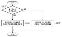
ステップS705では、算出したページの幅と高さの比より、基準区画サイズの整数倍となる表示領域を持つ表示区画サイズの算出を行う。ここでは、ページの幅と高さの比は1:4未満でないため、処理はステップS707へ進み、表示区画サイズは基準区画サイズと等倍のサイズとなる。 In step S705, the display section size having a display area that is an integral multiple of the reference section size is calculated from the calculated ratio between the width and height of the page. Here, since the ratio between the width and the height of the page is not less than 1: 4, the process proceeds to step S707, and the display partition size is the same size as the reference partition size.
ここで、横方向に縮小画像を表示する場合は、ステップS705〜ステップS707までの処理が図10に示すフローチャートのようになる。 Here, when displaying a reduced image in the horizontal direction, the processing from step S705 to step S707 is as shown in the flowchart of FIG.
即ち、ステップS705′で基準区画サイズの整数倍となる表示領域をもつ表示区画サイズの算出を行う。ここでは、ページの幅と高さの比が4:1以上かどうかで倍率を算出する。4:1以上である場合、処理はステップS706′へ進み、表示区画サイズは基準区画サイズの横に2倍に設定し、その後、処理はステップS708へ進む。これに対して、4:1以上でない場合、処理はステップS707′へ進み、表示区画サイズは基準区画サイズの等倍に設定し、その後処理はステップS708へ進む。 That is, in step S705 ′, the display section size having a display area that is an integral multiple of the reference section size is calculated. Here, the magnification is calculated based on whether the ratio of the page width to the height is 4: 1 or more. If it is 4: 1 or more, the process proceeds to step S706 ′, the display section size is set to be double the reference section size, and then the process proceeds to step S708. On the other hand, if it is not 4: 1 or more, the process proceeds to step S707 ′, the display section size is set to the same size as the reference section size, and the process proceeds to step S708.
次にステップS708において、表示区画サイズに内接する拡大縮小率を算出する。ここでは、幅が2480ピクセル、高さが3508ピクセルのページを幅が90ピクセル、高さが120ピクセルの表示区画に内接するようにするため、拡大縮小率は3.42%となる。ステップS709では、算出された拡大縮小率3.42%でページ901を縮小する。さらに、ステップS710で縮小したページを表示区画に表示する。 In step S708, the enlargement / reduction ratio inscribed in the display section size is calculated. Here, since the page having a width of 2480 pixels and a height of 3508 pixels is inscribed in a display section having a width of 90 pixels and a height of 120 pixels, the enlargement / reduction ratio is 3.42%. In step S709, the page 901 is reduced at the calculated enlargement / reduction ratio of 3.42%. Further, the page reduced in step S710 is displayed in the display area.
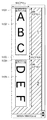
図13はページの縮小画像が表示された縮小画像表示部509である。
FIG. 13 shows a reduced
図13において、1101は1ページ目の文書の表示区画であり、そこに1ページ目の文書の縮小画像1102が表示される。
In FIG. 13,
次に、処理はステップS711において、現在処理対象のページが最終ページかどうかを判定する。ここでは、1ページ目の後に2ページ目904があるので、処理はステップS712へ進み、処理対象を文書の次のページである2ページ目904に設定する。次にステップS713では、次の表示区画の前に余白を挿入する。ここでは、1ページ目の文書の表示区画である1101の次に縦方向に20ピクセルの余白1103を挿入する。
Next, in step S711, the process determines whether the current processing target page is the last page. Here, since there is the second page 904 after the first page, the process advances to step S712 to set the processing target to the second page 904 that is the next page of the document. In step S713, a margin is inserted before the next display section. Here, a
その後、処理はステップS703に戻り、処理対象ページである2ページ目904の幅と高さを取得する。次に、ステップS704ではページの幅と高さの比を算出し、ステップS705において算出したページの幅と高さの比より、基準区画サイズの整数倍となる表示領域をもつ表示区画サイズの算出を行う。ここでは、ページの幅と高さの比は2480:10524であり、その比が1:4未満のため、処理はステップS706へ進む。ページの幅と高さの比の算出結果により、表示区画サイズは基準区画サイズの縦に整数倍した2倍のサイズとなる幅90ピクセル、高さ240ピクセルとなる。 Thereafter, the process returns to step S703, and the width and height of the second page 904 that is the processing target page are acquired. Next, in step S704, the ratio between the width and height of the page is calculated, and the display section size having a display area that is an integer multiple of the reference section size is calculated from the ratio between the page width and height calculated in step S705. I do. Here, since the ratio between the width and the height of the page is 2480: 10524 and the ratio is less than 1: 4, the process proceeds to step S706. Based on the calculation result of the ratio between the width and the height of the page, the display partition size is 90 pixels wide and 240 pixels high, which is twice as long as an integer multiple of the reference partition size.
図13の1104は表示区画サイズの算出結果により求まった2ページ目904の表示区画である。
次に、ステップS708において表示区画サイズに内接するように拡大縮小率2.28%が求まる。ステップS709では、算出した拡大縮小率2.28%でページ904を縮小する。図13における1005が縮小されたページであり、これを表示区画1104に表示する。
In step S708, an enlargement / reduction ratio of 2.28% is obtained so as to be inscribed in the display section size. In step S709, the page 904 is reduced at the calculated enlargement / reduction ratio of 2.28%. Reference numeral 1005 in FIG. 13 denotes a reduced page, which is displayed in the
再び処理はステップS711において、現在処理対象のページが最終ページかどうかを判定する。ここでは、現在処理対象の2ページ目904が文書の最終ページであるため、この処理を終了する。 In step S711, the process again determines whether the current page to be processed is the last page. Here, since the second page 904 to be processed is the last page of the document, this process ends.
この実施例に従うページ一覧縮小画像表示処理(ステップS105)により、ページの縮小画像を表示する区画サイズは、ページの幅と高さの比より基準区画サイズの整数倍となる。従って、長尺ページの縮小画像を表示する場合でも、視認性が損なわれることはない。 By the page list reduced image display processing according to this embodiment (step S105), the partition size for displaying the reduced image of the page is an integral multiple of the reference partition size from the ratio of the page width and height. Accordingly, even when a reduced image of a long page is displayed, the visibility is not impaired.
なお、ページとは画像ファイルそのものを示すこともあり、以降の実施例においても同様の意味で用いる。 Note that a page may indicate an image file itself, and is used in the same meaning in the following embodiments.
さて、縮小画像の一覧表示においては、図14に示すように視認性向上のために縮小画像と縮小画像との間に一律の余白幅を設けて一覧表示することが一般的である。このように縮小画像の表示区画サイズが全て同一の場合には、各縮小画像を表示する座標を予め定めておくことで、一律の余白幅を設けることができる。 In the list display of reduced images, as shown in FIG. 14, it is common to display a list with a uniform margin width between the reduced image and the reduced image in order to improve visibility. As described above, when the display area sizes of the reduced images are all the same, a uniform margin width can be provided by setting the coordinates for displaying each reduced image in advance.
しかしながら、図3〜図4に示すように記録媒体がロール紙を用いる構成のプリンタの場合には、1ページの長さが可変であり、縮小画像表示部には基準区画サイズの表示区画サイズと基準区画サイズの整数倍の表示区画サイズの縮小画像が混在して表示される。 However, as shown in FIGS. 3 to 4, in the case of a printer having a configuration in which the recording medium uses roll paper, the length of one page is variable, and the reduced image display portion has a display section size of the reference section size. Reduced images having a display section size that is an integral multiple of the reference section size are displayed together.
図15は縮小画像表示部の表示例を示す図である。 FIG. 15 is a diagram illustrating a display example of the reduced image display unit.
図15には比較のために、各縮小画像の座標の位置を固定にして表示を行なった場合を(a)に比較例として示されている。 For comparison, FIG. 15 shows, as a comparative example, a case where display is performed with the coordinate position of each reduced image fixed.
図15において、2701、2702、2703は同じピクセル数を持つ余白である。基準区画サイズを整数倍(この場合は2倍)した表示区画サイズの縮小画像の後ろには、図15(a)に示すように、整数倍−1個分(この場合は1個分)の余白2702が追加される。その結果、縮小画像と縮小画像の間の余白幅が一律ではなくなり視認性が低下する。
In FIG. 15, 2701, 2702, and 2703 are margins having the same number of pixels. As shown in FIG. 15A, behind the reduced image of the display section size obtained by multiplying the reference section size by an integer multiple (in this case, twice), an integer multiple minus one (in this case, one) A
これに対して、この実施例に従う縮小画像表示部では固定座標を使用した一覧表示は行わず、表示区画サイズが決定した後に、意図的に余白の挿入を行なっている(ステップS713)。これにより、図15(b)に示されているように、基準区画サイズと基準区画サイズを整数倍した表示区画サイズが混在した場合においても、一律の余白幅で一覧表示される。これにより、縮小画像の視認性が向上する。 On the other hand, the reduced image display unit according to this embodiment does not display a list using fixed coordinates, and intentionally inserts a blank after determining the display section size (step S713). As a result, as shown in FIG. 15B, even when the reference section size and the display section size obtained by multiplying the reference section size by an integer are mixed, a list is displayed with a uniform margin width. Thereby, the visibility of the reduced image is improved.
この実施例では、実施例1に基づいて文書の縮小画像を表示する場合に、縮小画像を表示する方向を切り替える動作について説明する。 In this embodiment, an operation for switching the display direction of a reduced image when a reduced image of a document is displayed based on the first embodiment will be described.
なお、実施例1で説明したのと共通の構成については説明を省略する。
Note that a description of the same configuration as that described in
図8で言及したフローチャートによれば、ステップS101では印刷プレビューダイアログを表示する。 According to the flowchart mentioned in FIG. 8, a print preview dialog is displayed in step S101.
図16は実施例2に従う印刷プレビューダイアログ表示処理の詳細を示すフローチャートである。 FIG. 16 is a flowchart showing details of the print preview dialog display process according to the second embodiment.
この実施例では、図16に示すフローチャートの処理に従って、印刷プレビューダイアログを表示する。 In this embodiment, a print preview dialog is displayed according to the processing of the flowchart shown in FIG.
まず、ステップS1201で文書の全ページの幅と高さを取得し、ステップS1202では全ページの幅と高さの比を算出し、ステップS1203ではページの幅と高さの比が3:1以上のページがあるかどうかを調べる。 First, the width and height of all pages of the document are acquired in step S1201, the ratio of the width and height of all pages is calculated in step S1202, and the ratio of page width and height is 3: 1 or more in step S1203. Check if there are any pages.
ここで、ページの幅と高さの比が3:1以上のページがない場合、処理はステップS1204へ進み、縮小画像の表示方向を縦方向に設定し、ステップS1205で縦方向に縮小画像を表示する印刷プレビューダイアログ501を表示する。
If there is no page having a page width / height ratio of 3: 1 or more, the process advances to step S1204 to set the display direction of the reduced image in the vertical direction, and in step S1205, the reduced image is displayed in the vertical direction. A
これに対して、ページの幅と高さの比が3:1以上のページがある場合、処理はステップS1206へ進み、縮小画像の表示方向を横方向に設定し、ステップS1207で横方向に縮小画像を表示する印刷プレビューダイアログ601を表示する。
On the other hand, if there is a page with a ratio of the page width to the height of 3: 1 or more, the process proceeds to step S1206, the reduced image display direction is set to the horizontal direction, and the horizontal direction is reduced in step S1207. A
この後、図8で言及したステップS102〜ステップS104を実行する。 Thereafter, steps S102 to S104 referred to in FIG. 8 are executed.
次に、ステップS105でページ一覧縮小画像表示処理を行う。 In step S105, page list reduced image display processing is performed.
ここで、縮小画像の表示方向が縦方向に設定された場合は、図9に示したフローチャートに基づき、縮小画像表示処理を行う。これに対して、縮小画像の表示方向が横方向に設定された場合は、図9〜図10に示したフローチャートに基づき、縮小画像表示処理を行う。この場合、図9のステップS705〜S707の処理は、ステップS705′〜S707′処理になる。なお、図9〜図10の処理についても実施例1と同じであるため、ここでは説明を省略する。 Here, when the display direction of the reduced image is set to the vertical direction, the reduced image display process is performed based on the flowchart shown in FIG. On the other hand, when the display direction of the reduced image is set to the horizontal direction, the reduced image display process is performed based on the flowcharts shown in FIGS. In this case, steps S705 to S707 in FIG. 9 are steps S705 ′ to S707 ′. Note that the processing in FIGS. 9 to 10 is the same as that in the first embodiment, and thus the description thereof is omitted here.
最後に、ステップS106で印刷プレビュー表示を行った後、処理を終了する。ステップS106についても実施例1と同じであるため、ここでは説明を省略する。 Finally, after the print preview display is performed in step S106, the process ends. Since step S106 is also the same as that in the first embodiment, the description thereof is omitted here.
従って以上説明した実施例に従えば、文書を構成するページの縮小画像を表示する方向を切り替えることが可能である。これにより、縮小画像表示部509で表示される縮小画像は基準区画サイズ、又はその縦または横に整数倍となる表示区画サイズ内に最大の大きさで表示することができる。
Therefore, according to the embodiment described above, it is possible to switch the direction in which the reduced image of the page constituting the document is displayed. As a result, the reduced image displayed on the reduced
この実施例では、実施例1に基づいて、向きが異なるページで構成されている文書の縮小画像を表示する場合に、縮小画像を回転させ表示する動作について説明する。 In this embodiment, an operation for rotating and displaying a reduced image when displaying a reduced image of a document composed of pages with different orientations will be described based on the first embodiment.
図17は実施例3に従うページ一覧縮小画像表示処理の詳細を示すフローチャートである。 FIG. 17 is a flowchart showing details of the page list reduced image display process according to the third embodiment.
図18は実施例3に従う印刷プレビュー制御部208に渡された文書を示す図である。
FIG. 18 is a diagram illustrating a document transferred to the print
図18において、1401は1ページ目のデータを表しており、1402は1ページ目の幅、1403は1ページ目の高さである。また、1404は2ページ目のデータを表しており、1405は2ページ目の幅、1406は2ページ目の高さである。 In FIG. 18, 1401 represents the data of the first page, 1402 represents the width of the first page, and 1403 represents the height of the first page. 1404 represents the data of the second page, 1405 is the width of the second page, and 1406 is the height of the second page.
図19は実施例3に従ってページの縮小画像が表示された縮小画像表示部を示す図である。 FIG. 19 is a diagram illustrating a reduced image display unit on which a reduced image of a page is displayed according to the third embodiment.
図19において、1501は1ページ目の文書の表示区画を表しており、1502は1ページ目の文書の縮小画像を表している。1503は1ページ目と2ページ目の表示区画の間に挿入した余白を、1504は1ページ目の文書の表示区画を、そして、1505は1ページ目の文書の縮小画像を表している。
In FIG. 19,
図20は実施例3に従って縮小画像を回転させ表示する動作を示した図である。 FIG. 20 is a diagram illustrating an operation of rotating and displaying a reduced image according to the third embodiment.
図20において、1601は回転前の表示区画、1602は回転前の縮小画像、1603は回転後の表示区画、1604は回転後の縮小画像を表している。
In FIG. 20,
なお、実施例1で説明したのと共通の構成については説明を省略する。
Note that a description of the same configuration as that described in
図8で言及したフローチャートに示されたステップS101〜S104、ステップS106をこの実施例でも実行するが、これらは実施例1と同じであり、ここでは説明を省略する。 Although steps S101 to S104 and step S106 shown in the flowchart referred to in FIG. 8 are also executed in this embodiment, these are the same as those in the first embodiment, and a description thereof will be omitted here.
図8によれば、次に、ステップS105でページ一覧縮小画像表示処理を行うが、これについては、図17を参照しながら説明する。 According to FIG. 8, next, the page list reduced image display process is performed in step S105, which will be described with reference to FIG.
まず、ステップS1301において、基準区画サイズの決定を行う。ここでは実施例1と同じ図12に示した基準区画を用い、基準区画サイズの幅1002を90ピクセル、基準区画サイズの高さ1003を120ピクセルとする。
First, in step S1301, the reference section size is determined. Here, the same reference section shown in FIG. 12 as in the first embodiment is used, the reference
次に、ステップS1302では処理対象のページを文書の最初のページ1401とし、ステップS1303では、このページの幅と高さを取得する。ここでは、処理対象であるページ1401の幅1402と高さ1403が取得された幅と高さであり、幅が2480ピクセル、高さが10524ピクセルとなる。
Next, in step S1302, the page to be processed is the first page 1401 of the document, and in step S1303, the width and height of this page are acquired. Here, the
ステップS1304では、ページの幅と高さの比を算出する。ここでは、ページの幅と高さの比は2480:10524となる。 In step S1304, the ratio between the page width and the height is calculated. Here, the ratio between the width and the height of the page is 2480: 10524.
ステップS1305では、算出したページの幅と高さの比より、基準区画サイズの整数倍となる表示領域をもつ表示区画サイズを算出する。ここで、ページの幅と高さの比は2480:10524であり、その比は1:4未満のため、処理はステップS1306へ進み、表示区画サイズは基準区画サイズの縦に2倍のサイズとなる。図19において、1501はこの算出により求まった1ページ目の表示区画を示し、幅90ピクセル、高さ240ピクセルである。
In step S1305, the display section size having a display area that is an integral multiple of the reference section size is calculated from the ratio of the calculated page width and height. Here, since the ratio between the width and the height of the page is 2480: 10524, and the ratio is less than 1: 4, the process proceeds to step S1306, and the display partition size is twice as large as the reference partition size. Become. In FIG. 19,
さらにステップS1309では、表示区画サイズに内接する拡大縮小率を算出する。幅が2480ピクセル、高さが10524ピクセルのページを幅が90ピクセル、高さが240ピクセルの表示区画に内接するような拡大縮小率は2.28%となる。ステップS1310では算出された拡大縮小率2.28%を用いてページ1401を縮小する。そして、ステップS1315で縮小したページを表示区画に表示する。その結果、図19に示す1ページ目の文書の表示区画1501に1ページ目の文書の縮小画像1502が表示される。
In step S1309, an enlargement / reduction ratio inscribed in the display section size is calculated. The enlargement / reduction ratio at which a page having a width of 2480 pixels and a height of 10524 pixels is inscribed in a display section having a width of 90 pixels and a height of 240 pixels is 2.28%. In step S1310, the page 1401 is reduced using the calculated enlargement / reduction ratio of 2.28%. Then, the page reduced in step S1315 is displayed in the display section. As a result, a
次に、処理はステップS1316において、現在処理対象のページが最終ページかどうかを判定する。ここでは、1ページ目の後に2ページ目1404があるので、処理はステップS1317へ進み、処理対象を文書の次のページである2ページ目1404に設定する。さらにステップS1318では、次の表示区画の前に余白を挿入する。ここでは、1ページ目の文書の表示区画1501の次に縦方向に20ピクセルの余白1503を挿入する。
Next, in step S1316, the process determines whether the current processing target page is the last page. Here, since there is a
その後、処理は再びステップS1303に戻り、処理対象ページである2ページ目1404の幅と高さを取得し、ステップS1304でページの幅と高さの比を算出する。ステップS1305では、算出したページの幅と高さの比より、基準区画サイズの整数倍となる表示領域をもつ表示区画サイズを算出する。ここでは、ページの幅と高さの比は10524:2048であり、その比は1:4未満ではないため、処理はステップS1307に進む。ステップS1307ではさらに、幅と高さの比が3:1以上かどうかで表示区画サイズの大きさを算出する。
Thereafter, the process returns to step S1303 again to acquire the width and height of the
ここで、その比は3:1以上であるため、処理はステップS1311へ進み、表示区画サイズは基準区画サイズの横に2倍のサイズとなる。これに対して、幅と高さの比が3:1以上でない場合、処理はステップS1308へ進み、表示区画サイズを基準区画サイズの等倍に設定する。図20において、1601はこの算出により求まった2ページ目1404の表示区画であり、幅240ピクセル、高さ90ピクセルとなる。
Here, since the ratio is 3: 1 or more, the process proceeds to step S1311, and the display section size is doubled to the side of the reference section size. On the other hand, if the ratio of width to height is not 3: 1 or more, the process advances to step S1308 to set the display section size to the same size as the reference section size. In FIG. 20,
次に、ステップS1312では、表示区画サイズに内接する拡大縮小率2.28%が求まる。ステップS1313では、算出された拡大縮小率2.28%を用いてページ1404を縮小する。図20において、1602が縮小されたページである。さらにステップS1314では表示区画1601と縮小したページ1602を右に90度回転させる。図20において、1603が回転後の表示区画であり、1604が回転後の縮小したページとなる。
Next, in step S1312, an enlargement / reduction ratio of 2.28% inscribed in the display section size is obtained. In step S1313, the
処理はステップS1315に進み、縮小したページを表示区画に表示する。縮小画像表示部509に表示された2ページ目の表示区画と2ページ目の縮小画像が図19における1504と1505である。
The process advances to step S1315 to display the reduced page in the display area. The display area of the second page and the reduced image of the second page displayed on the reduced
最後にステップS1316で現在処理対象のページが最終ページかどうかを判定する。ここでは、現在処理対象の2ページ目1404が文書の最終ページであるため、処理を終了する。
Finally, in step S1316, it is determined whether the current processing target page is the last page. Here, since the
これらの処理の後、図8に示すフローチャートによれば、ステップS106で印刷プレビュー表示処理を行い、その後処理が終了する。前述のとおりステップS106の処理は実施例1と同様のため、ここでは説明を省略する。 After these processes, according to the flowchart shown in FIG. 8, the print preview display process is performed in step S106, and then the process ends. As described above, since the process of step S106 is the same as that of the first embodiment, the description thereof is omitted here.
従って以上説明した実施例に従えば、表示区画と縮小したページを回転させて表示することができる。これにより、縦方向に長いページと横方向に長いページとが混在する文書の縮小画像を表示する場合でも、いずれかの方向に長いページの縮小画像が小さくなり、ページの内容が視認できなくなることがないという利点がある。 Therefore, according to the embodiment described above, the display section and the reduced page can be rotated and displayed. As a result, even when a reduced image of a document having a mixture of pages that are long in the vertical direction and long pages in the horizontal direction is displayed, the reduced image of the page that is long in either direction becomes smaller and the contents of the page cannot be visually recognized. There is an advantage that there is no.
ここでは、表示画面に表示される複数の縮小画像の間の余白が適切に設けられる例について説明する。 Here, an example in which margins between a plurality of reduced images displayed on the display screen are appropriately provided will be described.
実施例1で言及した図14に示されているように、複数の縮小画像を表示画面に表示する場合には、互いの間に余白がある。通常、図14に示すように、複数の縮小画像を表示する複数の基準区画1701〜1712は等間隔になるように余白が設けられる。
As shown in FIG. 14 referred to in the first embodiment, when a plurality of reduced images are displayed on the display screen, there is a space between them. Normally, as shown in FIG. 14, a plurality of
図21はこの実施例で用いる基準区画サイズを示した図であり、図14に示した基準区画1701〜1712は等間隔に配置される。
FIG. 21 is a diagram showing the reference section size used in this embodiment, and the
図21において、1801は基準区画サイズの幅、1802は基準区画サイズの高さ、1803は基準区画サイズ間の横方向の間隔、1804は基準区画サイズ間の縦方向の間隔である。また、1803と1804は基準区画サイズと基準区画サイズとの間の余白部分である。
In FIG. 21, 1801 is the width of the reference section size, 1802 is the height of the reference section size, 1803 is the horizontal distance between the reference section sizes, and 1804 is the vertical distance between the reference section sizes.
図22はこの記録システムで記録に用いる画像ファイルの一例を示す図である。 FIG. 22 is a diagram showing an example of an image file used for recording in this recording system.
図22において、1901から1906は画像ファイルのデータとその画像サイズを示している。ここに示す画像ファイルについては1901から1906までを順に処理するものとする。
In FIG. 22,
図23は図22に示した画像ファイルの縮小画像を表示したユーザインタフェースを示す図である。 FIG. 23 is a diagram showing a user interface displaying the reduced image of the image file shown in FIG.
次に、図22に示すような画像ファイルをプレビューする場合の、この実施例に従う縮小画像表示処理についてフローチャートを参照して説明する。 Next, reduced image display processing according to this embodiment when previewing an image file as shown in FIG. 22 will be described with reference to a flowchart.
図24は実施例4に従う縮小画像表示処理の詳細を示すフローチャートである。 FIG. 24 is a flowchart showing details of the reduced image display processing according to the fourth embodiment.
まず、ステップS2101では基準区画サイズを決定する。ここでは、基準区画サイズの幅1801を128ピクセル、基準区画サイズの高さ1802を96ピクセルとする。
First, in step S2101, the reference section size is determined. Here, the
次にステップS2102では、基準区画サイズを図14に示すようにに等間隔に配置する。具体的には、図21に示すように、基準区画サイズ間の横方向の間隔1803を26ピクセル、基準区画サイズ間の縦方向の間隔1408を26ピクセルとし、図14に示すように基準区画1701〜1712を配置する。以降、これらの基準区画に関して処理を行う場合は1701から1712までを順に処理するものとする。
Next, in step S2102, the reference section sizes are arranged at regular intervals as shown in FIG. Specifically, as shown in FIG. 21, the
ステップS2103では処理対象のファイルを最初の画像ファイル1901に設定し、ステップS2104では処理対象の基準区画を最初の基準区画1701に設定する。
In step S2103, the processing target file is set as the
さらにステップS2105では、画像データの幅と高さを取得する。ここでは、画像ファイル1901の幅と高さを取得する。取得した画像データの幅は640ピクセル、高さは480ピクセルとなる。ステップS2106では、取得した画像データの幅と高さの比を算出する。ここでは、640:480となる。
In step S2105, the width and height of the image data are acquired. Here, the width and height of the
そして、ステップS2107では算出した比が所定の比未満かどうかを計算する。ここでは、算出した比640:480は2:1未満となるため、処理はステップS2111に進む。ステップS2111では、表示区画を現在の基準区画1つに設定する。ここでは、表示区画を1701に設定する。次にステップS2112で表示区画に内接する拡大縮小率を求める。ここでは、表示区画1701に画像ファイル1901が内接する拡大縮小率を求める。表示区画1701のサイズは基準区画のサイズなので、基準区画の幅1801の128ピクセル、高さは96ピクセルとなり、この表示区画に幅640ピクセル、高さ480ピクセルの画像ファイル1901が内接する拡大縮小率は20.0%となる。
In step S2107, it is calculated whether the calculated ratio is less than a predetermined ratio. Here, since the calculated ratio 640: 480 is less than 2: 1, the process proceeds to step S2111. In step S2111, the display section is set to one current reference section. Here, the display section is set to 1701. In step S2112, an enlargement / reduction ratio inscribed in the display section is obtained. Here, the enlargement / reduction ratio at which the
次にステップS2113では、画像ファイル1901の画像データをステップS2112で算出した拡大縮小率20.0%を用いて縮小する。ステップS2114では、縮小した画像データを表示区画に表示する。ここでは、ステップS2113で縮小した画像データを基準区画1701に表示する。図23の2001が画像ファイル1901の縮小画像を表示する表示区画であり、2002が表示された縮小画像である。
In step S2113, the image data of the
さらに処理は、ステップS2115において現在の処理対象ファイルが最終ファイルかどうかを判定する。ここでは、画像ファイル1902〜1906が未処理であるので、処理はステップS2116に進む。ステップS2116では、処理対象ファイルを次のファイルである画像ファイル1902に設定する。ステップS2117では処理対象の基準区画を次の基準区画1702に設定する。
In step S2115, the process determines whether the current process target file is the last file. Here, since the image files 1902-1906 are unprocessed, the process proceeds to step S2116. In step S2116, the processing target file is set to an
その後、処理はステップS2105に戻り、次の画像ファイルの画像データの幅と高さを取得する。ここでは、画像ファイル1902の幅と高さを取得する。取得した画像データの幅は1280ピクセル、高さは480ピクセルとなる。ステップS2106では取得した画像データの幅と高さの比を算出する。ここでは、1280:480となる。ステップS2107で算出した比が所定の比未満かどうかを計算する。ここでは、算出した比1280:480は2:1未満ではないため、処理はステップS2108に進む。
Thereafter, the process returns to step S2105 to acquire the width and height of the image data of the next image file. Here, the width and height of the
ステップS2108では、現在の基準区画の右隣に基準区画があるかを判定する。ここでは、現在の基準区画1702の右隣に基準区画1703があるので、処理はステップS2110に進む。これに対して、現在の基準区画の右隣に基準区画がない場合は、処理はステップS2109へ進み、処理対象の基準区画を次の行にある左端の基準区画に設定して、その後、処理はステップS2110に進む。
In step S2108, it is determined whether there is a reference section to the right of the current reference section. Here, since there is a
ステップS2110では、表示区画を現在の基準区画と右隣の基準区画1つを含む領域に設定する。ここでは、現在の基準区画1702とその右隣の基準区画1703を含む領域を表示区画に設定する。表示区画の幅は、基準区画1702の幅1801と基準区画間の横方向の余白1803と基準区画1703の幅1801の和、即ち、282ピクセルとなる。表示区画の高さは基準区画の高さ1802の96ピクセルとなる。即ち、基準区画サイズを横にN倍拡大(Nは正の整数)する場合には、(N−1)×余白ピクセル分の幅を追加した表示区画サイズに設定する。
In step S2110, the display section is set to an area including the current reference section and one reference section on the right. Here, an area including the
次にステップS2112では、表示区画に内接する拡大縮小率を求める。ここでは、ステップS2110で設定した表示区画に画像ファイル1902が内接する拡大縮小率を求める。即ち、幅282ピクセル、高さは96ピクセルの表示区画に幅1280ピクセル、高さ480ピクセルの画像データが内接する拡大縮小率は20.0%となる。
In step S2112, an enlargement / reduction ratio inscribed in the display section is obtained. Here, the enlargement / reduction ratio at which the
ステップS2113では、画像ファイル1902の画像データをステップS2112で算出した拡大縮小率20.0%を用いて縮小する。ステップS2114では、縮小した画像データを表示区画に表示する。図23における2003が画像ファイル1902の縮小画像を表示する表示区画であり、2004が表示された縮小画像である。
In step S2113, the image data of the
ステップS2115では、現在の処理対象ファイルが最終ファイルであるかどうかを判定する。ここでは、画像ファイル1903〜1906が未処理であるので、処理はステップS2116に進む。ステップS2116では、処理対象ファイルを次の画像ファイル1903に設定する。ステップS2117では、処理対象の基準区画を次の基準区画1704に設定する。
In step S2115, it is determined whether the current process target file is the last file. Here, since the image files 1903 to 1906 are unprocessed, the process proceeds to step S2116. In step S2116, the processing target file is set to the
以降同様に画像ファイル1906までの縮小画像を表示し、その後処理を終了する。
Thereafter, similarly, the reduced image up to the
このように、この実施例では画像ファイル1901〜1906において、画像データの幅と高さの比が2:1未満の場合は基準区画1つを表示区画とし、2:1以上の場合は隣接する1つの基準区画を含む領域を表示区画とする。そして、この表示区画に画像ファイルのデータを内接するように縮小させて表示する。これにより、画像ファイル1902、1904、1906のようなパノラマ画像の縮小画像表示は表示区画が隣接する1つの基準区画を含む領域に対してなされる。 As described above, in this embodiment, in the image files 1901-1906, when the ratio of the width and height of the image data is less than 2: 1, one reference section is set as the display section, and when the ratio is 2: 1 or more, it is adjacent. An area including one reference section is set as a display section. Then, the data of the image file is reduced and displayed so as to be inscribed in this display section. Thereby, the reduced image display of the panoramic image such as the image files 1902, 1904, and 1906 is performed on an area including one reference section adjacent to the display section.
従って、この実施例に従えば、表示区画の規則性が保持されたまま、縮小画像が表示されるため視認性が向上する。 Therefore, according to this embodiment, the reduced image is displayed while maintaining the regularity of the display section, so that the visibility is improved.
なお、実施例4では図22に示す画像ファイル1901〜1906のように、画像データの幅の比が1:2である横向き画像で説明したが、必ずしもこのように幅や高さや向きが統一されていなくてもよい。 In the fourth embodiment, a horizontal image having a ratio of image data width of 1: 2 has been described as in the image files 1901 to 1906 shown in FIG. 22, but the width, height, and direction are not necessarily unified in this way. It does not have to be.
その場合、実施例1から3で説明した方法によって、図14に示す縮小画像表示ユーザインタフェースにページを一覧表示させることが可能である。即ち、必要に応じて画像を回転し、基準区画サイズまたは基準区画サイズの整数倍に余白サイズを考慮した表示区画サイズに内接する拡大縮小率を計算し、その計算した拡大縮小率に従って縮小した画像を表示させれば良い。 In that case, it is possible to display a list of pages on the reduced image display user interface shown in FIG. 14 by the method described in the first to third embodiments. In other words, the image is rotated as necessary, the enlargement / reduction ratio inscribed in the reference division size or the display area size taking the margin size into an integral multiple of the reference division size is calculated, and the image reduced according to the calculated enlargement / reduction ratio May be displayed.
また、以上説明した実施例では、このようなプレビュー処理はホスト装置によって実行されるものとしたが、本発明はこれによって限定されるものではない。例えば、図3〜図4に示す大判プリンタの操作パネル部12に設けられたLCDなどの表示ディスプレイと操作キーなどを用いてプレビューを行わせても良い。この場合、ホスト装置より文書データやプレビュー処理を行うのに必要なデータが送信されるものとする。
In the embodiment described above, such a preview process is executed by the host device, but the present invention is not limited thereto. For example, the preview may be performed using a display such as an LCD provided on the
また、本発明に従う記録システムの制御プログラムは、CD−ROMやフレキシブルディスク等の記憶媒体から、又は電子メールやパソコン通信等のネットワークを介して、ホスト装置(PC)やその装置と接続する記録装置等にロードされ、実行されてもよい。例えば、記録装置のメモリやPCのHDDにこのプログラムを格納することができる。そして、記録装置のCPU或いはホスト装置のCPUがそのプログラムを実行することにより本発明を実現する。 The control program for the recording system according to the present invention includes a host device (PC) and a recording device connected to the device from a storage medium such as a CD-ROM or a flexible disk, or via a network such as e-mail or personal computer communication. Etc. and may be executed. For example, this program can be stored in the memory of a recording device or the HDD of a PC. The present invention is realized by the CPU of the recording apparatus or the CPU of the host apparatus executing the program.
さらに加えて、本発明のインクジェット記録装置の形態としては、コンピュータ等の情報処理機器の画像出力装置として用いられるものの他、リーダ等と組合せた複写装置、さらには送受信機能を有するファクシミリ装置の形態を採るもの等であってもよい。 In addition, the ink jet recording apparatus according to the present invention may be used as an image output apparatus for information processing equipment such as a computer, a copying apparatus combined with a reader, or a facsimile apparatus having a transmission / reception function. It may be one taken.
1 ホスト装置(パーソナルコンピュータ:PC)
2 プリンタ(記録装置)
203 OS
204 プリンタドライバ
205 アプリケーション
206 ユーザインタフェース部
207 グラフィックス処理部
208 印刷プレビュー制御部
209 プリンタ情報取得部
301 CPU
302 ROM
303 RAM
304 通信インタフェース(HDD)
305 外部記憶装置
306 入力部
307 出力部
1 Host device (personal computer: PC)
2 Printer (recording device)
203 OS
204
302 ROM
303 RAM
304 Communication interface (HDD)
305
Claims (8)
前記文書を構成する各ページの一覧を表示するための表示区画の基準サイズとなる第1の表示区画のサイズを設定する区画サイズ設定手段と、
前記文書データの各ページの幅と高さを取得する取得手段と、
前記取得手段により取得した各ページの幅と高さの比を示す値が所定の値より小さい場合に、前記第1の表示区画のサイズから前記第1の表示区画のサイズよりも大きい表示区画を有する第2の表示区画のサイズを算出する算出手段と、
前記第1または第2の表示区画に前記各ページが収まるように拡大縮小率を決定する決定手段と、
前記決定手段により決定された拡大縮小率に基づいて、前記文書データの各ページを拡大又は縮小して、前記第1または第2の表示区画に表示することにより、前記文書を構成する各ページの一覧を表示する表示手段とを有することを特徴とする記録システム。 Host device capable of generating document data of a document composed of a plurality of pages having different sizes , and a recording device for receiving document data from the host device and recording an image based on the document data on a recording medium A recording system consisting of
A partition size setting means for setting a size of the first display section as a reference size of the display section for displaying a list of the pages constituting the document,
Obtaining means for obtaining the width and height of each page of the document data;
When the value indicating the ratio of the width and height of each page acquired by the acquisition unit is smaller than a predetermined value, a larger display area than the size of the first display area from the size of the first pane Calculating means for calculating the size of the second display section having ;
Determining means for determining an enlargement / reduction ratio so that each page fits in the first or second display section;
Based on the scaling factor determined by the determination means, by enlarging or reducing each page of the document data, by displaying on the first or second pane, of each page constituting the document A recording system comprising display means for displaying a list.
前記表示手段は、前記判定手段による判定の結果に従って、前記ページを回転させて表示することを特徴とする請求項1又は2に記載の記録システム。 From the ratio of the width and height ratio and each page width and height of the first or the size of the second display section, that displays to the page is rotated in the first or second display section A determination means for determining whether or not
The recording system according to claim 1 , wherein the display unit rotates and displays the page according to a result of determination by the determination unit.
前記文書を構成する各ページの一覧を表示するための表示区画の基準サイズとなる第1の表示区画のサイズを設定する区画サイズ設定手段と、
前記受信した文書データの各ページの幅と高さを取得する取得手段と、
前記取得手段により取得した各ページの幅と高さの比を示す値が所定の値より小さい場合に、前記第1の表示区画のサイズから前記第1の表示区画のサイズよりも大きい表示区画を有する第2の表示区画のサイズを算出する算出手段と、
前記第1または第2の表示区画に前記各ページが収まるように拡大縮小率を決定する決定手段と、
前記決定手段により決定された拡大縮小率に基づいて、前記文書データの各ページを拡大又は縮小して、前記第1または第2の表示区画に表示することにより、前記文書を構成する各ページの一覧を表示する表示手段とを有することを特徴とする記録装置。 A recording device that receives document data generated in a host device capable of generating document data of a document composed of a plurality of pages having different sizes and records an image based on the document data on a recording medium. And
A partition size setting means for setting a size of the first display section as a reference size of the display section for displaying a list of the pages constituting the document,
Obtaining means for obtaining the width and height of each page of the received document data;
When the value indicating the ratio of the width and height of each page acquired by the acquisition unit is smaller than a predetermined value, a larger display area than the size of the first display area from the size of the first pane Calculating means for calculating the size of the second display section having ;
Determining means for determining an enlargement / reduction ratio so that each page fits in the first or second display section;
Based on the scaling factor determined by the determination means, by enlarging or reducing each page of the document data, by displaying on the first or second pane, of each page constituting the document And a display unit for displaying a list.
前記文書を構成する各ページの一覧を表示するための表示区画の基準サイズとなる第1の表示区画のサイズを設定する区画サイズ設定工程と、
前記文書データの各ページの幅と高さを取得する取得工程と、
前記取得工程において取得した各ページの幅と高さの比を示す値が所定の値より小さい場合に、前記第1の表示区画のサイズから前記第1の表示区画のサイズよりも大きい表示区画を有する第2の表示区画のサイズを算出する算出工程と、
前記第1または第2の表示区画に前記各ページが収まるように拡大縮小率を決定する決定工程と、
前記決定工程において決定された拡大縮小率に基づいて、前記文書データの各ページを拡大又は縮小して、前記第1または第2の表示区画に表示することにより、前記文書を構成する各ページの一覧を表示する表示工程とを有することを特徴とする記録システムのプレビュー方法。 Host device capable of generating document data of a document composed of a plurality of pages having different sizes , and a recording device for receiving document data from the host device and recording an image based on the document data on a recording medium A preview method in the host device of the recording system comprising :
A partition size setting step of setting a size of the first display section as a reference size of the display section for displaying a list of the pages constituting the document,
An acquisition step of acquiring the width and height of each page of the document data;
When the value indicating the ratio of the width and height of each page acquired in the acquiring step is smaller than a predetermined value, a larger display area than the size of the first display area from the size of the first pane a calculation step of calculating the size of the second display section having,
A determination step of determining an enlargement / reduction ratio so that each page fits in the first or second display section;
Based on the scaling factor determined in the determination step, by enlarging or reducing the each page of the document data, by displaying on the first or second pane, of each page constituting the document A recording system preview method comprising: a display step of displaying a list.
Priority Applications (6)
| Application Number | Priority Date | Filing Date | Title |
|---|---|---|---|
| JP2007337666A JP4891216B2 (en) | 2007-12-27 | 2007-12-27 | Recording system, recording apparatus, and recording system preview method |
| EP08171177.2A EP2075687B1 (en) | 2007-12-27 | 2008-12-10 | Preview method for printing system |
| US12/338,831 US8098398B2 (en) | 2007-12-27 | 2008-12-18 | Printing system, printing apparatus, and preview method for printing system |
| KR1020080135016A KR101073310B1 (en) | 2007-12-27 | 2008-12-26 | Printing system, printing apparatus, and preview method for printing system |
| CN201210351034.6A CN102902495B (en) | 2007-12-27 | 2008-12-29 | The pre-viewing device of print system and the method for previewing of print system |
| CN200810189474XA CN101470592B (en) | 2007-12-27 | 2008-12-29 | Printing system, printing apparatus, and preview method for printing system |
Applications Claiming Priority (1)
| Application Number | Priority Date | Filing Date | Title |
|---|---|---|---|
| JP2007337666A JP4891216B2 (en) | 2007-12-27 | 2007-12-27 | Recording system, recording apparatus, and recording system preview method |
Publications (3)
| Publication Number | Publication Date |
|---|---|
| JP2009159498A JP2009159498A (en) | 2009-07-16 |
| JP2009159498A5 JP2009159498A5 (en) | 2011-02-10 |
| JP4891216B2 true JP4891216B2 (en) | 2012-03-07 |
Family
ID=40454479
Family Applications (1)
| Application Number | Title | Priority Date | Filing Date |
|---|---|---|---|
| JP2007337666A Active JP4891216B2 (en) | 2007-12-27 | 2007-12-27 | Recording system, recording apparatus, and recording system preview method |
Country Status (5)
| Country | Link |
|---|---|
| US (1) | US8098398B2 (en) |
| EP (1) | EP2075687B1 (en) |
| JP (1) | JP4891216B2 (en) |
| KR (1) | KR101073310B1 (en) |
| CN (2) | CN102902495B (en) |
Families Citing this family (10)
| Publication number | Priority date | Publication date | Assignee | Title |
|---|---|---|---|---|
| US8363237B1 (en) * | 2009-04-17 | 2013-01-29 | System Development, Inc. | Active printing system and method for printing based on image size |
| JP2012148450A (en) * | 2011-01-18 | 2012-08-09 | Canon Inc | Printing method and printing apparatus |
| JP5097288B2 (en) * | 2011-04-28 | 2012-12-12 | シャープ株式会社 | Image forming apparatus |
| CN102289497A (en) * | 2011-08-22 | 2011-12-21 | 上海梅花信息有限公司 | Document preview image generating system and method |
| US8749836B2 (en) | 2012-08-06 | 2014-06-10 | Hewlett-Packard Development Company, L.P. | Page image treatment |
| JP5995090B2 (en) * | 2013-02-14 | 2016-09-21 | 富士ゼロックス株式会社 | Display device, image forming apparatus, and program |
| DE102013214025B4 (en) * | 2013-07-17 | 2017-08-24 | Koenig & Bauer Ag | Method for printing a substrate |
| GB201513371D0 (en) * | 2015-07-29 | 2015-09-09 | Videojet Technologies Inc | A machine and method for its operation |
| JP7301630B2 (en) * | 2019-06-28 | 2023-07-03 | キヤノン株式会社 | Program, control device and control method |
| US11029895B2 (en) * | 2019-11-12 | 2021-06-08 | Cimpress Schweiz Gmbh | Technologies for positioning designs on virtual surfaces associated with product customization |
Family Cites Families (13)
| Publication number | Priority date | Publication date | Assignee | Title |
|---|---|---|---|---|
| US6256109B1 (en) * | 1996-05-29 | 2001-07-03 | Richard Rosenbaum | Image enlargement system |
| JP3769868B2 (en) | 1997-04-18 | 2006-04-26 | 富士ゼロックス株式会社 | Document management device |
| JP4328426B2 (en) * | 1999-11-02 | 2009-09-09 | キヤノン株式会社 | Printing control method and apparatus |
| JP2001186334A (en) * | 1999-12-27 | 2001-07-06 | Canon Inc | Device, system and method for picture processing, and storage medium |
| WO2003021475A1 (en) * | 2001-08-31 | 2003-03-13 | Brother Kogyo Kabushiki Kaisha | Character string edition apparatus and program |
| JP4409897B2 (en) * | 2003-09-19 | 2010-02-03 | 株式会社リコー | Image processing apparatus, image processing method, program, and information recording medium |
| JP4837248B2 (en) * | 2003-10-29 | 2011-12-14 | 京セラ株式会社 | Image display device and control method of image display device |
| JP2005208723A (en) * | 2004-01-20 | 2005-08-04 | Seiko Epson Corp | Printing apparatus and medium type setting method |
| KR100571788B1 (en) | 2004-01-20 | 2006-04-18 | 삼성전자주식회사 | The method of printing the appointed domain of document enlargeably |
| KR20050104022A (en) | 2004-04-27 | 2005-11-02 | 삼성전자주식회사 | Apparatus and method for enlarge and reduce printing |
| JP2006092185A (en) * | 2004-09-22 | 2006-04-06 | Fuji Xerox Co Ltd | Information processor and print control method therefor |
| JP4525405B2 (en) * | 2005-03-24 | 2010-08-18 | 富士ゼロックス株式会社 | Print image display device, print image display method, and print image display program |
| EP1821189B1 (en) * | 2006-02-15 | 2014-07-23 | Canon Kabushiki Kaisha | Host apparatus and printing control method |
-
2007
- 2007-12-27 JP JP2007337666A patent/JP4891216B2/en active Active
-
2008
- 2008-12-10 EP EP08171177.2A patent/EP2075687B1/en active Active
- 2008-12-18 US US12/338,831 patent/US8098398B2/en active Active
- 2008-12-26 KR KR1020080135016A patent/KR101073310B1/en active IP Right Grant
- 2008-12-29 CN CN201210351034.6A patent/CN102902495B/en not_active Expired - Fee Related
- 2008-12-29 CN CN200810189474XA patent/CN101470592B/en active Active
Also Published As
| Publication number | Publication date |
|---|---|
| EP2075687A1 (en) | 2009-07-01 |
| CN102902495A (en) | 2013-01-30 |
| US20090168081A1 (en) | 2009-07-02 |
| EP2075687B1 (en) | 2016-03-09 |
| KR20090071500A (en) | 2009-07-01 |
| JP2009159498A (en) | 2009-07-16 |
| CN102902495B (en) | 2015-10-21 |
| KR101073310B1 (en) | 2011-10-12 |
| US8098398B2 (en) | 2012-01-17 |
| CN101470592A (en) | 2009-07-01 |
| CN101470592B (en) | 2012-10-24 |
Similar Documents
| Publication | Publication Date | Title |
|---|---|---|
| JP4891216B2 (en) | Recording system, recording apparatus, and recording system preview method | |
| US8081342B2 (en) | Information processing apparatus, information processing method, and print control program | |
| US20040207859A1 (en) | Information processing apparatus and print preview display method | |
| JP2011203826A (en) | Apparatus and method for processing image, and program | |
| US7409169B2 (en) | Image forming apparatus and image forming system | |
| JP4630847B2 (en) | Information processing apparatus, information processing method, and program | |
| US20220129225A1 (en) | Control method, information processing apparatus, and print system | |
| JP2007233591A (en) | Printer driver and its test printing method and printer | |
| JP2004058651A (en) | Printing controller, method of controlling printing, printing control program, and memory medium containing the program | |
| US20120026541A1 (en) | Printing control apparatus, printing apparatus, and print preview method | |
| US20090303499A1 (en) | Image forming apparatus, image forming system and enlargement print processing method of printing data | |
| US8564824B2 (en) | System and printing method to generate printing data of an image to be printed over a plurality of recording pages | |
| US8976412B2 (en) | Method and system for recognizing tab sheets and displaying one or more sets of tabs sheets on a graphical user interface | |
| JP4665806B2 (en) | Printing apparatus, printing method, and printing program | |
| US20100165406A1 (en) | Split Large Image Printing | |
| JP2005280285A (en) | Recording device with internal storage means | |
| JP2004038778A (en) | Printing system, printer host, program, and printer driver | |
| KR100538241B1 (en) | Print option displaying and printing method | |
| JP2008273015A (en) | Image processor and image processing method | |
| JP2015115010A (en) | Print controller and print control method | |
| JP2009116736A (en) | Printing system | |
| JP2012108831A (en) | Printer driver, printing method and printing system | |
| JP2005108143A (en) | Print system, printing control unit, and printing support program |
Legal Events
| Date | Code | Title | Description |
|---|---|---|---|
| A521 | Request for written amendment filed |
Free format text: JAPANESE INTERMEDIATE CODE: A523 Effective date: 20101217 |
|
| A621 | Written request for application examination |
Free format text: JAPANESE INTERMEDIATE CODE: A621 Effective date: 20101217 |
|
| A977 | Report on retrieval |
Free format text: JAPANESE INTERMEDIATE CODE: A971007 Effective date: 20111110 |
|
| TRDD | Decision of grant or rejection written | ||
| A01 | Written decision to grant a patent or to grant a registration (utility model) |
Free format text: JAPANESE INTERMEDIATE CODE: A01 Effective date: 20111118 |
|
| A01 | Written decision to grant a patent or to grant a registration (utility model) |
Free format text: JAPANESE INTERMEDIATE CODE: A01 |
|
| A61 | First payment of annual fees (during grant procedure) |
Free format text: JAPANESE INTERMEDIATE CODE: A61 Effective date: 20111215 |
|
| R151 | Written notification of patent or utility model registration |
Ref document number: 4891216 Country of ref document: JP Free format text: JAPANESE INTERMEDIATE CODE: R151 |
|
| FPAY | Renewal fee payment (event date is renewal date of database) |
Free format text: PAYMENT UNTIL: 20141222 Year of fee payment: 3 |