JP4890974B2 - Image processing apparatus and image processing method - Google Patents
Image processing apparatus and image processing method Download PDFInfo
- Publication number
- JP4890974B2 JP4890974B2 JP2006180379A JP2006180379A JP4890974B2 JP 4890974 B2 JP4890974 B2 JP 4890974B2 JP 2006180379 A JP2006180379 A JP 2006180379A JP 2006180379 A JP2006180379 A JP 2006180379A JP 4890974 B2 JP4890974 B2 JP 4890974B2
- Authority
- JP
- Japan
- Prior art keywords
- pixel
- value
- colors
- image
- replacement
- Prior art date
- Legal status (The legal status is an assumption and is not a legal conclusion. Google has not performed a legal analysis and makes no representation as to the accuracy of the status listed.)
- Expired - Fee Related
Links
- 238000012545 processing Methods 0.000 title claims abstract description 141
- 238000003672 processing method Methods 0.000 title claims description 4
- 239000003086 colorant Substances 0.000 claims abstract description 28
- 238000000034 method Methods 0.000 claims abstract description 26
- 230000008569 process Effects 0.000 claims abstract description 10
- 238000012937 correction Methods 0.000 claims description 64
- 238000004364 calculation method Methods 0.000 claims description 16
- 230000001133 acceleration Effects 0.000 description 24
- 230000006870 function Effects 0.000 description 16
- 238000006243 chemical reaction Methods 0.000 description 11
- 230000008859 change Effects 0.000 description 8
- 238000010586 diagram Methods 0.000 description 8
- 230000000694 effects Effects 0.000 description 7
- 238000007639 printing Methods 0.000 description 7
- 238000009499 grossing Methods 0.000 description 4
- 230000003287 optical effect Effects 0.000 description 4
- 230000002093 peripheral effect Effects 0.000 description 3
- 238000004891 communication Methods 0.000 description 2
- 230000004069 differentiation Effects 0.000 description 2
- 238000009792 diffusion process Methods 0.000 description 2
- 238000000605 extraction Methods 0.000 description 2
- 239000011159 matrix material Substances 0.000 description 2
- 238000007788 roughening Methods 0.000 description 2
- 238000003705 background correction Methods 0.000 description 1
- 230000008901 benefit Effects 0.000 description 1
- 239000000470 constituent Substances 0.000 description 1
- 238000013461 design Methods 0.000 description 1
- 238000001514 detection method Methods 0.000 description 1
- 238000005516 engineering process Methods 0.000 description 1
- 230000002349 favourable effect Effects 0.000 description 1
- 238000007667 floating Methods 0.000 description 1
- 238000003702 image correction Methods 0.000 description 1
- 238000009434 installation Methods 0.000 description 1
- 239000004973 liquid crystal related substance Substances 0.000 description 1
- 238000013139 quantization Methods 0.000 description 1
- 230000009467 reduction Effects 0.000 description 1
- 238000006467 substitution reaction Methods 0.000 description 1
- 238000012546 transfer Methods 0.000 description 1
Images


Classifications
-
- H—ELECTRICITY
- H04—ELECTRIC COMMUNICATION TECHNIQUE
- H04N—PICTORIAL COMMUNICATION, e.g. TELEVISION
- H04N1/00—Scanning, transmission or reproduction of documents or the like, e.g. facsimile transmission; Details thereof
- H04N1/46—Colour picture communication systems
- H04N1/56—Processing of colour picture signals
- H04N1/58—Edge or detail enhancement; Noise or error suppression, e.g. colour misregistration correction
-
- G—PHYSICS
- G06—COMPUTING; CALCULATING OR COUNTING
- G06T—IMAGE DATA PROCESSING OR GENERATION, IN GENERAL
- G06T5/00—Image enhancement or restoration
- G06T5/20—Image enhancement or restoration using local operators
-
- G—PHYSICS
- G06—COMPUTING; CALCULATING OR COUNTING
- G06T—IMAGE DATA PROCESSING OR GENERATION, IN GENERAL
- G06T5/00—Image enhancement or restoration
- G06T5/73—Deblurring; Sharpening
-
- G—PHYSICS
- G06—COMPUTING; CALCULATING OR COUNTING
- G06T—IMAGE DATA PROCESSING OR GENERATION, IN GENERAL
- G06T2207/00—Indexing scheme for image analysis or image enhancement
- G06T2207/10—Image acquisition modality
- G06T2207/10004—Still image; Photographic image
- G06T2207/10008—Still image; Photographic image from scanner, fax or copier
-
- G—PHYSICS
- G06—COMPUTING; CALCULATING OR COUNTING
- G06T—IMAGE DATA PROCESSING OR GENERATION, IN GENERAL
- G06T2207/00—Indexing scheme for image analysis or image enhancement
- G06T2207/10—Image acquisition modality
- G06T2207/10024—Color image
-
- G—PHYSICS
- G06—COMPUTING; CALCULATING OR COUNTING
- G06T—IMAGE DATA PROCESSING OR GENERATION, IN GENERAL
- G06T2207/00—Indexing scheme for image analysis or image enhancement
- G06T2207/20—Special algorithmic details
- G06T2207/20004—Adaptive image processing
- G06T2207/20012—Locally adaptive
-
- G—PHYSICS
- G06—COMPUTING; CALCULATING OR COUNTING
- G06T—IMAGE DATA PROCESSING OR GENERATION, IN GENERAL
- G06T2207/00—Indexing scheme for image analysis or image enhancement
- G06T2207/20—Special algorithmic details
- G06T2207/20172—Image enhancement details
- G06T2207/20192—Edge enhancement; Edge preservation
-
- G—PHYSICS
- G06—COMPUTING; CALCULATING OR COUNTING
- G06T—IMAGE DATA PROCESSING OR GENERATION, IN GENERAL
- G06T2207/00—Indexing scheme for image analysis or image enhancement
- G06T2207/30—Subject of image; Context of image processing
- G06T2207/30176—Document
Landscapes
- Engineering & Computer Science (AREA)
- Physics & Mathematics (AREA)
- General Physics & Mathematics (AREA)
- Theoretical Computer Science (AREA)
- Multimedia (AREA)
- Signal Processing (AREA)
- Facsimile Image Signal Circuits (AREA)
- Image Processing (AREA)
- Color Image Communication Systems (AREA)
Abstract
Description
本発明は、画像に補正処理を施す画像処理装置、及び画像処理方法に関する。 The present invention relates to an image processing apparatus and an image processing method for performing correction processing on an image.
従来から、画像に補正処理を加える画像処理装置が知られている。例えば、複写機のスキャナで光学的に読み取った画像のエッジは、原稿画像のエッジに比べてなだらかになり、このまま記録媒体上に印刷を施すとシャープ感が損なわれた画像になる。また、シャープ感を出す目的で読み取り後にエッジ強調処理としてエッジ強調フィルタを実施すると、オーバシュートやアンダシュートと呼ばれる、文字の縁が強調されすぎて不自然な画像になってしまう。また、読み取り時に発生したノイズが強調されてしまうという問題が生じる。また読み取り時に発生するモアレが強調されてしまうという問題が生じる。そこで、これらの問題を解決するために、周辺の画素で注目画素を置き換えるという技術が提案されてきた(特許文献1参照)。
しかしながら、上記の従来技術では、複数色の画像信号がある場合に、適切な補正手段を提供できなかった。例えば、特許文献1に記載の技術では、複数色毎に独立して画像信号の分布形状による判別処理を行うと、カラー画像に適した画像強調信号を作成することができず、色ずれを起こしていた。
However, the above-described conventional technology cannot provide an appropriate correction means when there are a plurality of color image signals. For example, in the technique described in
さらに、画像信号の分布形状を調べる場合に、フィルタのサイズを大きくすると計算量が増加し、アンシャープ信号を作成するための処理が増加してしまうという課題があった。 Further, when examining the distribution shape of the image signal, there is a problem that if the size of the filter is increased, the amount of calculation increases and the processing for creating an unsharp signal increases.
本発明は、上記従来技術の課題を解決するためになされたもので、その目的は、複数色の画像信号からなる画像に対しても、適切な補正処理を行なうことにある。 The present invention has been made to solve the above-described problems of the prior art, and an object of the present invention is to perform an appropriate correction process even on an image composed of a plurality of color image signals.
上記目的を達成するため、本発明に係る画像処理装置は、複数色に対応した信号値を有する複数の画素毎に補正処理を行う画像処理装置であって、
処理対象画素を含む複数の画素に対応する画像領域を設定する設定手段と、
前記画像領域に含まれる画素毎に、前記複数色に対応した信号値から輝度値を生成する生成手段と、
前記画像領域に含まれる複数の画素間における、前記生成手段により生成された前記輝度値の相対的な大小関係に基づいて、前記処理対象画素の前記信号値と置換するための置換候補画素を、前記画像領域に含まれる複数の画素の中から決定する決定手段と、
前記処理対象画素の前記複数色に対応した信号値と、前記置換候補画素の前記複数色に対応した信号値とを用いて、前記処理対象画素の前記複数色に対応した信号値と前記置換候補画素の前記複数色に対応した信号値との間の値となるように、前記処理対象画素の信号値を置換するための置換信号値を算出する算出手段と、
前記算出手段により算出された前記置換信号値で、前記処理対象画素の信号値を置換する置換手段と、
を有することを特徴とする。
In order to achieve the above object, an image processing apparatus according to the present invention is an image processing apparatus that performs correction processing for each of a plurality of pixels having signal values corresponding to a plurality of colors,
Setting means for setting an image region corresponding to a plurality of pixels including a processing target pixel;
For each pixel contained in the image area, and generate unit that generates a luminance value from the signal values corresponding to the plurality of colors,
A replacement candidate pixel for replacing the signal value of the processing target pixel based on the relative magnitude relationship of the luminance value generated by the generation unit between a plurality of pixels included in the image region , Determining means for determining from among a plurality of pixels included in the image region;
Using the signal value corresponding to the plurality of colors of the processing target pixel and the signal value corresponding to the plurality of colors of the replacement candidate pixel, the signal value corresponding to the plurality of colors of the processing target pixel and the replacement candidate Calculating means for calculating a replacement signal value for replacing the signal value of the processing target pixel so as to be a value between signal values corresponding to the plurality of colors of the pixel ;
Replacement means for replacing the signal value of the processing target pixel with the replacement signal value calculated by the calculation means ;
It is characterized by having.
本発明によれば、複数色の画像信号からなる画像に対しても、適切な補正処理を行なうことができる。 According to the present invention, it is possible to perform an appropriate correction process even on an image composed of a plurality of color image signals.
以下に、図面を参照して、この発明の好適な実施の形態を例示的に詳しく説明する。ただし、この実施の形態に記載されている構成要素はあくまで例示であり、この発明の範囲をそれらのみに限定する趣旨のものではない。 Hereinafter, exemplary embodiments of the present invention will be described in detail with reference to the drawings. However, the constituent elements described in this embodiment are merely examples, and are not intended to limit the scope of the present invention only to them.
<MFPの構成>
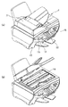
図1は、本発明の実施の形態に係るマルチファンクションプリンタ(以下、MFP)1の概観斜視図である。図1(a)は、MFP1のADF(オートドキュメントフィーダ)31部分を閉じた状態であり、図1(b)は、開いた状態である。
<Configuration of MFP>
FIG. 1 is a schematic perspective view of a multifunction printer (hereinafter, MFP) 1 according to an embodiment of the present invention. FIG. 1A shows a state where an ADF (auto document feeder) 31 portion of the
このMFP1は、基本的に、ホストコンピュータ(PC)からデータを受信してプリントするプリンタとしての機能及びスキャナとしての機能を有する。さらにMFP単体で動作する機能として、スキャナで読取った画像をプリンタで印刷するコピー機能、メモリカードなどの記憶媒体から画像データを読取って印刷する機能、或いはデジタルカメラからの画像データを受信して印刷する機能を備えている。
The
図1において、MFP1はフラットベットスキャナなどのスキャニングユニット14、インクジェット式や電子写真式などによるプリントユニット13を備えている。また、表示パネル等のディスプレイユニット19や各種キースイッチ等を備えるオペレーションユニット15を備えている。更に、MFP1の背面にはPCと通信するためのUSBポート(不図示)が設けられ、PCとの通信が行われる。各種メモリカードからデータを読み出すためのカードスロットを含むカードインタフェイス22やデジタルカメラとデータ通信を行うためのカメラポートを含むカメラインタフェイス23が設けられている。MFP1は、他にも、自動で原稿を原稿台にセットするためのADF31などを備えている。
In FIG. 1, the MFP 1 includes a
図2は、MFP1の内部構成を示すブロック図である。図2において、CPU11は、MFP1が備える様々な機能を制御し、オペレーションユニット15の所定の操作に従い、ROM16に記憶された画像処理のプログラムを実行する。プログラムを実行することにより、CPU11が処理対象画素を選択したり、処理対象画素を含む予め定められた大きさの画像領域を抽出したりできる。また、CPU11は、画像領域内に含まれる画素の信号値から、処理対象画素に関する変動量や変動回数や変動加速度を算出することもできる。ROM16には、画像処理に用いられる様々なテーブルや数式が格納されており、変動量や変動回数や変動加速度と様々な補正強度との対応関係を設定する設定手段として機能する。CCDを備えるスキャニングユニット14は、原稿画像を読取り、赤(R)、緑(G)および青(B)色のアナログ輝度データを出力する。なお、スキャニングユニット14は、CCDの代わりに密着型イメージセンサ(CIS)を備えてもよい。また、ADF31を備えれば、連続でオーダーシートを読取ることができ更に簡便である。
FIG. 2 is a block diagram showing the internal configuration of the
また、カードインターフェイス22は、例えばディジタルスチルカメラ(Digital Still Camere:以下DSC)で撮影され、メモリカードなどに記録された画像データを、オペレーションユニット15に対する操作に従い読み込む。なお、カードインターフェイス22を介して読み込まれた画像データの色空間は、必要ならば、画像処理部12により、DSCの色空間(例えばYCbCr)から標準的なRGB色空間(例えばNTSC−RGBやsRGB)に変換される。また、そのヘッダ情報に基づき、読み込まれた画像データは、有効な画素数への解像度変換など、アプリケーションに必要な様々な処理が必要に応じて施される。また、カメラインターフェイス23は、DSCに直接接続して画像データを読み込むためのものである。
In addition, the
画像処理部12においては、読取り信号値の変換、画像の補正・加工処理、輝度信号(RGB)から濃度信号(CMYK)への変換、スケーリング、ガンマ変換、誤差拡散等の画像処理が行われる。画像処理部12が行なう補正処理としては、エッジ強調処理、平滑化処理、置換処理、及び無彩色化処理などが含まれ、補正手段として機能する。画像処理部12での画像処理によって得られるデータは、RAM17に格納される。RAM17に格納された補正データが所定量に達すると、プリントユニット13による記録動作が実行される。
The image processing unit 12 performs image processing such as conversion of a read signal value, image correction / processing, conversion from a luminance signal (RGB) to a density signal (CMYK), scaling, gamma conversion, and error diffusion. The correction processing performed by the image processing unit 12 includes edge enhancement processing, smoothing processing, replacement processing, and achromatic processing, and functions as correction means. Data obtained by image processing in the image processing unit 12 is stored in the
不揮発性RAM18としては、バッテリバックアップされたSRAMなどを用いることができ、MFP1に固有のデータなどを記憶する。オペレーションユニット15は、記憶媒体(メモリカード)に記憶された画像データを選択し、記録をスタートするためのフォトダイレクトプリントスタートキーを備え、オーダーシートをプリントさせるキー、オーダーシートを読み込ますキー等を備える。また、モノクロコピー時やカラーコピー時におけるコピースタートキー、コピー解像度や画質などのモードを指定するモードキー、コピー動作などを停止するためのストップキー、並びに、コピー数を入力するテンキーや登録キーなどを備えてもよい。CPU11は、これらキーの押下状態を検出し、その状態に応じて各部を制御する。
As the
ディスプレイユニット19は、ドットマトリクスタイプの液晶表示部(LCD)およびLCDドライバを備え、CPU11の制御に基づき各種表示を行う。また、記憶媒体に記録されていた画像データのサムネイルを表示する。プリントユニット13は、インクジェット方式のインクジェットヘッド、汎用ICなどによって構成され、CPU11の制御により、RAM17に格納されている記録データを読み出し、ハードコピーとしてプリント出力する。
The
ドライブユニット21は、スキャニングユニット14およびプリントユニット13を動作させるため、給排紙ローラを駆動するステッピングモータ、ステッピングモータの駆動力を伝達するギヤ、および、ステッピングモータを制御するドライバ回路などを含む。
The drive unit 21 includes a stepping motor that drives the paper supply / discharge roller, a gear that transmits the driving force of the stepping motor, a driver circuit that controls the stepping motor, and the like in order to operate the
センサユニット20は、記録紙幅センサ、記録紙有無センサ、原稿幅センサ、原稿有無センサおよび記録媒体検知センサなどを含む。CPU11は、このセンサユニット20から得られる情報に基づき、原稿および記録紙の状態を検知する。
The
PCインターフェイス24はPCとのインターフェイスであり、MFP1はPCインターフェイス24を介してPCからのプリント、スキャンなどの動作を行う。コピー動作時は、スキャニングユニット14で読取った画像データをMFP内部でデータ処理し、プリントユニット13で印刷する。
The
オペレーションユニット15により、コピー動作が指示されると、スキャニングユニット14は原稿台に置かれた原稿を読取る。読取られたデータは画像処理部12に送られ、画像処理が施された後、プリントユニット13に送られ印刷が行われる。
When a copy operation is instructed by the
<画像処理>
図3はコピー時に実行される画像処理のフローチャートである。以下、各ステップについて説明を記述する。スキャニングユニット14で読取られ、AD変換された画像データに対し、撮像素子のばらつきを補正するために、STEP301において、シェーディング補正が施される。
<Image processing>
FIG. 3 is a flowchart of image processing executed at the time of copying. Hereinafter, description will be given for each step. In step 301, shading correction is performed on the image data read by the
その後、STEP302で、入力デバイス色変換が行われる。これによりデバイス固有であった信号データが標準的な色空間領域へと変換される。標準的な色空間領域としては、IEC(国際電気標準会議;International Electrotechnical Commission)により定められたsRGBがある。また、Adobe Systems社により提唱されているAdobeRGBでもよい。変換方法は、3x3や3x9のマトリクスによる演算方式や、変換規則を記載したテーブルに基づいて決定するルックアップテーブル方式などが挙げられる。 Thereafter, in STEP 302, input device color conversion is performed. As a result, the signal data unique to the device is converted into a standard color space region. As a standard color space region, there is sRGB defined by the IEC (International Electrotechnical Commission). Alternatively, AdobeRGB proposed by Adobe Systems may be used. Examples of the conversion method include a calculation method using a 3 × 3 or 3 × 9 matrix, a lookup table method that is determined based on a table in which conversion rules are described, and the like.
変換されたデータは、STEP303において、補正・加工の処理が施される。処理内容としては、読取りによるボケを補正するエッジ強調処理や、文字の判読性を向上させる文字加工処理、光照射による読取りで発生した裏写りを除去する処理などが挙げられる。 STEP304では、拡大縮小処理が実行され、ユーザにより変倍指定がされている場合や、2枚の原稿を一枚の紙に割り当てる割付けコピーなどで、所望の倍率に変換される。変換方法は、バイキュービックやニアレストネイバーなどの方法が一般的である。 The converted data is corrected and processed in STEP 303. Examples of processing contents include edge enhancement processing that corrects blurring due to reading, character processing processing that improves character readability, and processing that removes show-through caused by reading by light irradiation. In STEP 304, enlargement / reduction processing is executed, and the magnification is converted to a desired magnification, for example, when zooming is designated by the user, or by allocation copying in which two originals are assigned to one sheet of paper. As a conversion method, methods such as bicubic and nearest neighbor are common.
STEP305では、標準色な色空間上のデータを、出力デバイスに固有の信号データへと変換する。本実施の形態に係るMFPは、インクジェット方式であり、シアン、マゼンタ、イエロー、ブラックなどのインク色データへの変換処理が実行される。この変換もSTEP302と同様の方式を用いればよい。 In STEP 305, data in a standard color space is converted into signal data unique to the output device. The MFP according to the present embodiment is an inkjet method, and conversion processing into ink color data such as cyan, magenta, yellow, and black is executed. For this conversion, a method similar to STEP 302 may be used.
さらに、STEP306において、記録可能なレベル数への変換が行われる。例えば、インクドットを打つ/打たないの2値で表現する場合あれば、誤差拡散などの量子化方法において、2値化すればよい。これによりプリンタが記録可能なデータ形式となり、それに基づいて記録動作が実行され、画像が形成される。 Further, in STEP 306, conversion to the number of recordable levels is performed. For example, if the ink dot is expressed with a binary value of whether or not the ink dot is applied, it may be binarized in a quantization method such as error diffusion. As a result, a data format that can be recorded by the printer is obtained, and a recording operation is executed based on the data format to form an image.
<処理単位>
図4(a)は属性判定処理を実施する際の処理単位を説明する図である。図4(a)の○印の画素を注目画素(処理の対象となる画素)とすると、図4(a)の太線のように注目画素を含む7×7画素で構成される領域(7×7領域)を設定する。この設定した7×7領域内の画像信号を用いて注目画素に対する画像処理を実行する。注目画素の処理が実行された後は、例えば図4(b)の×印の画素のように注目画素に隣接する画素を次の注目画素と設定し、同様に7×7領域を設定して画像処理を実行する。以降、同様に順次注目画素を1画素ずつ移動し、その都度7×7領域を設定することによって対象の画素全てを補正する。
<Processing unit>
FIG. 4A is a diagram for explaining a processing unit when performing the attribute determination processing. If a pixel marked with a circle in FIG. 4A is a pixel of interest (a pixel to be processed), a region (7 × 7) including 7 × 7 pixels including the pixel of interest as indicated by a thick line in FIG. 7 areas). Image processing for the target pixel is executed using the image signal in the set 7 × 7 region. After the processing of the target pixel is executed, for example, a pixel adjacent to the target pixel is set as the next target pixel, such as a pixel marked with x in FIG. 4B, and a 7 × 7 region is similarly set. Perform image processing. Thereafter, similarly, the target pixel is sequentially moved one pixel at a time, and all the target pixels are corrected by setting a 7 × 7 area each time.
次に処理単位が領域単位の場合を説明する。図4(a)の○印の画素に対して7×7領域を設定し、○印に対して設定する補正強度を7×7領域内の複数画素、例えば全画素に適用する。次の処理は図4(c)の△印の画素に対して7×7領域を設定することで○印に対する7×7領域と△印に対する7×7領域とが隣接するように処理単位を移動する。 ただし、処理単位を画素単位とした方がより高い精度で補正強度を設定できる為、本実施の形態は、処理単位を画素単位として説明する。 Next, a case where the processing unit is an area unit will be described. The 7 × 7 area is set for the pixels marked with “◯” in FIG. 4A, and the correction strength set for the marks “◯” is applied to a plurality of pixels in the 7 × 7 area, for example, all pixels. In the next processing, by setting a 7 × 7 area for the pixel marked Δ in FIG. 4C, the processing unit is set so that the 7 × 7 area for the circle and the 7 × 7 area for the triangle are adjacent to each other. Moving. However, since the correction intensity can be set with higher accuracy when the processing unit is the pixel unit, the present embodiment will be described using the processing unit as the pixel unit.
図5は処理単位の移動フローを説明する図である。STEP501は処理対象設定である。START直後は、最初の処理対象を設定する。STEP505からSTEP501に戻った場合は、次の処理対象を設定する。 FIG. 5 is a diagram for explaining the movement flow of processing units. STEP 501 is a processing target setting. Immediately after START, the first processing target is set. When returning from STEP 505 to STEP 501, the next processing target is set.
STEP502は処理領域設定である。処理領域とは前記説明したように処理単位を含む複数画素(前記説明では7×7領域)で構成される領域である。
STEP503は補正強度設定である。処理単位に対する補正強度を設定する。
STEP504は補正実行である。STEP503で設定した補正強度を使って処理単位を補正する。
STEP505は最終補正対象判定である。処理単位が最後の処理単位であるか否かを判定する。最後の処理単位でなければ(NO)STEP501に戻る。最後の処理単位であれば(YES)ENDとなる。
STEP 502 is processing area setting. As described above, the processing area is an area composed of a plurality of pixels (7 × 7 area in the above description) including a processing unit.
STEP 503 is a correction intensity setting. Sets the correction strength for the processing unit.
STEP 504 is correction execution. The processing unit is corrected using the correction strength set in STEP 503.
STEP 505 is a final correction target determination. It is determined whether the processing unit is the last processing unit. If it is not the last processing unit (NO), return to STEP501. If it is the last processing unit (YES), it becomes END.
以下の実施の形態では処理領域を7×7領域として説明している。これはスキャニングユニット14で使っているCCDまたはCISの撮像素子1画素が読む原稿の画素範囲を6画素以内とするよう設計した為である。尚、6画素以内の設計と言っても、原稿台からの原稿の浮きや原稿の凹凸等によって、撮像素子に入射する原稿からの反射光は種々の影響を受ける。その為、実際には6画素を超える範囲を読み取る場合もある。以下の実施の形態において原稿を読み取った画像信号の説明図を複数示すが、これらの画像信号も必ずしも6画素以内の反射光とは限らない。
In the following embodiment, the processing area is described as a 7 × 7 area. This is because the pixel range of the original read by one pixel of the CCD or CIS image sensor used in the
図6は撮像素子1画素に入る原稿からの反射光範囲を簡易的に示している。本実施の形態で使用した撮像素子は、図6(a)に示すように撮像素子1画素に対して、原稿の7画素範囲から6画素以内の反射光が入射するよう設計している(前述したように場合によっては6画素を超える場合もある)。つまり、原稿の1画素の反射光は撮像素子7画素に影響している。これが背景技術で述べたエッジのボケを発生し、シャープ感を損なっている。 FIG. 6 simply shows the range of reflected light from a document entering one pixel of the image sensor. The image sensor used in the present embodiment is designed so that reflected light within 6 pixels from the 7 pixel range of the document is incident on one pixel of the image sensor as shown in FIG. In some cases, the number of pixels may exceed 6). That is, the reflected light of one pixel of the document affects the seven pixels of the image sensor. This causes the blurring of the edge described in the background art and impairs the sharpness.
以下の実施の形態はボケを低減することを目的の1つとしている。注目画素を置換候補画素で置換してエッジを強調する。よって、注目画素に対応する原稿画素の影響が少ない画素領域から置換候補を選択するとエッジ強調の効果は高い。そこで最低限、原稿画像の1画素の影響を受けている領域は処理領域として確保した。だから、7×7領域を処理領域と設定している。エッジ強調の効果をより高くする為、7×7を超える領域を参照領域とすることも有効である。また、図6(b)に示すように撮像素子1画素に対して、原稿の3画素範囲から反射光が入射する設計とした場合は、処理領域を3×3領域のように小さく設定してもよい。 The following embodiment is aimed at reducing blur. The target pixel is replaced with a replacement candidate pixel to enhance the edge. Therefore, when a replacement candidate is selected from a pixel area where the influence of the original pixel corresponding to the target pixel is small, the effect of edge enhancement is high. Therefore, at least, an area affected by one pixel of the original image is secured as a processing area. Therefore, the 7 × 7 area is set as the processing area. In order to further enhance the effect of edge enhancement, it is also effective to set a region exceeding 7 × 7 as a reference region. Also, as shown in FIG. 6B, when the reflected light is designed to be incident on one pixel of the image sensor from the three-pixel range of the document, the processing area is set as small as a 3 × 3 area. Also good.
また、より高速な処理を行なう目的で処理データ量を削減するために、有効画素を間引く、または隣あう画素を加算一体化処理をするなどして、撮像素子の解像度より低い読み取り解像度で読み取る場合がある。このような場合には7x7よりも小さい領域を参照領域とすることも有効である。反対に、より高解像度で読み込む場合には、処理領域を7x7より大きく設定することが有効である。 In addition, in order to reduce the amount of processing data for the purpose of higher-speed processing, when reading with a reading resolution lower than the resolution of the image sensor by thinning out effective pixels or adding and integrating adjacent pixels There is. In such a case, it is also effective to set an area smaller than 7 × 7 as a reference area. On the other hand, when reading at a higher resolution, it is effective to set the processing area to be larger than 7 × 7.
このように参照領域は原稿画像1画素が影響する撮像素子の画素数や、スポット径、ボケ画素数、Modulation Transfer Function(MTF)等の撮像素子の性能に応じて適宜設定すればよい。 As described above, the reference area may be set as appropriate according to the number of pixels of the image sensor affected by one pixel of the document image, the spot diameter, the number of blurred pixels, the modulation transfer function (MTF), and the like.
<言葉の定義>
以下に、本明細書中で用いられる言葉の定義について説明する。
変動量とは、処理対象画素を中心とする周辺画素群における、画素信号値の変動の大きさを表わす値である。本実施形態では、1画素の両側に隣接する2画素の輝度値の差分の絶対値(エッジ量)のうち、最大のものを変動量として説明するが、これに限定されるものではない。注目する画素の画像信号に関連する値の1次微分の絶対値等、変化の差分(大きさ)を表現する値、または注目する領域内の画像信号に関連する値の変化の差分(大きさ)を代表して表現する値であってもよい。
<Definition of words>
Hereinafter, the definition of terms used in this specification will be described.
The fluctuation amount is a value representing the magnitude of fluctuation of the pixel signal value in the peripheral pixel group centered on the processing target pixel. In the present embodiment, the maximum value among the absolute values (edge amounts) of the difference between the luminance values of two pixels adjacent to both sides of one pixel will be described as the variation amount, but the present invention is not limited to this. A value expressing a difference (magnitude) of change, such as an absolute value of a first derivative of a value related to an image signal of a pixel of interest, or a difference (magnitude) of a value relating to an image signal in a region of interest ) As a representative value.
変動回数とは、処理対象画素を中心とする周辺画素群における、画素信号値の変動の頻度を表わす値である。本実施形態では、画像領域内の1画素の両側に隣接する2画素の輝度値の差分の増減頻度(符号変化数(ゼロ交差点数))を変動回数として説明するが、これに限定されるものではない。画像領域内の画像信号に関連する値の1次微分の零交差点数や空間周波数、2値化後の黒白の変化数等、画像信号に関連する値の変化の頻度を表現する値であると定義する。 The number of changes is a value representing the frequency of change in pixel signal value in a peripheral pixel group centering on the pixel to be processed. In the present embodiment, the increase / decrease frequency (number of code changes (number of zero crossings)) of the difference between the luminance values of two pixels adjacent to both sides of one pixel in the image area will be described as the number of fluctuations, but the present invention is not limited to this. is not. It is a value that represents the frequency of change in values related to the image signal, such as the number of zero-crossing points of the first derivative of the value related to the image signal in the image area, the spatial frequency, the number of black and white changes after binarization, etc. Define.
変動加速度とは、処理対象画素を中心とする周辺画素群における、画素信号値の変動の加速度を表わす値である。以下の実施の形態では画像領域内の輝度の差分からさらに差をとった値として説明するが、これに限定されるものではない。注目する領域内の画像信号に関連する値の2次微分等、変化の加速度を表現する値であればよい。 The fluctuation acceleration is a value representing the acceleration of fluctuation of the pixel signal value in the peripheral pixel group centering on the processing target pixel. In the following embodiments, a value obtained by further taking a difference from the luminance difference in the image area will be described, but the present invention is not limited to this. Any value that expresses the acceleration of change, such as a second derivative of a value related to the image signal in the region of interest, may be used.
彩度とは、以下の実施の形態では注目する画素または領域における各色の画像信号差の内、最大絶対値として説明するが、これに限定されるものではない。度軸からの距離を表現する値であると定義する。 In the following embodiment, the saturation is described as the maximum absolute value among the image signal differences of each color in the pixel or region of interest, but is not limited to this. It is defined as a value that expresses the distance from the degree axis.
適応的に補正強度を設定するとは、定義した変動回数、変動量、変動加速度、彩度の夫々取り得る値領域の内、夫々少なくとも一部の値領域において、夫々の値毎に異なる補正強度を設定することであると定義する。 Setting the correction strength adaptively means that different correction strengths are set for each value in at least a part of the value range of the defined number of fluctuations, fluctuation amount, fluctuation acceleration, and saturation. Define that it is to be set.
以下、本実施の形態の画像処理の詳細を説明する。尚、画像信号の取り得る範囲を0〜255を例に説明するが、画像信号の範囲はこれに限るものではなく、MFP、画像処理に適するよう設定すればよい。 Details of the image processing according to the present embodiment will be described below. The range that the image signal can take will be described by taking 0 to 255 as an example. However, the range of the image signal is not limited to this, and may be set to be suitable for the MFP and image processing.
図14は本実施形態の補正強度設定のフローチャートである。フローチャートのステップに沿って補正強度設定を説明する。 FIG. 14 is a flowchart of correction intensity setting according to this embodiment. The correction intensity setting will be described along the steps of the flowchart.
<補正強度設定STEP2501:処理領域設定>
RGBの多値の画像信号で構成される画像において、処理対象となる注目画素を中心とした横7画素、縦7画素で構成される7×7領域の処理領域を抽出する。処理領域の各画素値R、G、Bから式(1)に従って代表信号値としての輝度Lを算出し、Lの7×7領域の処理領域を生成する。
L = (R+2×G+B)/4 ・・・式(1)
尚、本実施の形態は式(1)で算出した輝度Lを用いているが、別の輝度を適用してもよい。例えば、明度と色差成分を含む画像信号を対象にしても良く、均等色空間L*a*b*のL*を輝度としてもいい。また、YCbCrのYを輝度としてもよいし、RGBのGのみを取り出してこれをLとしてもよい。このように特定の色を全体の代表とすると演算量が少なくてすむため、実現回路が簡単になる。
<Correction intensity setting STEP 2501: Processing area setting>
In an image composed of RGB multi-valued image signals, a processing region of 7 × 7 regions composed of 7 horizontal pixels and 7 vertical pixels centering on the target pixel to be processed is extracted. A luminance L as a representative signal value is calculated from each pixel value R, G, B of the processing region according to the equation (1), and a processing region of 7 × 7 regions of L is generated.
L = (R + 2 × G + B) / 4 Formula (1)
Although the present embodiment uses the luminance L calculated by Equation (1), other luminance may be applied. For example, an image signal including brightness and color difference components may be targeted, and L * in the uniform color space L * a * b * may be used as the luminance. Further, Y of YCbCr may be set as luminance, or only G of RGB may be extracted and set as L. In this way, if a specific color is used as a representative of the whole, the amount of calculation can be reduced, and the implementation circuit becomes simple.
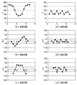
図7(a1)は白背景中の黒縦線を横方向に読み取った際の輝度を示している。図7(a2)は白背景中の横方向に並んだ網点を横方向に読み取った際の輝度を示している。 FIG. 7A1 shows the luminance when the black vertical line in the white background is read in the horizontal direction. FIG. 7A2 shows the luminance when the halftone dots arranged in the horizontal direction in the white background are read in the horizontal direction.
<補正強度設定STEP2502:4方向抽出>
STEP2501で生成したLの処理領域から図8に示すように横1方向、縦1方向、斜2方向の合計4方向の各7画素を抽出する。
<Correction intensity setting STEP2502: Extraction in 4 directions>
As shown in FIG. 8, 7 pixels in a total of 4 directions of 1 horizontal direction, 1 vertical direction, and 2 diagonal directions are extracted from the L processing region generated in STEP 2501.
<補正強度設定STEP2503:L差分算出>
STEP2502で抽出した4方向のLから、特徴量として各方向5画素のLの差分Grdを図9と式(2)に示すように算出する。ここで、画素L(i)の前画素をL(i−1)と後画素をL(i+1)とする。
Grd(i) = L(i+1)−L(i−1) ・・・式(2)
式(2)はデジタル信号値の一次微分をあらわしている。尚、L差分の算出方法はこれに限らず、隣接同士の差分でもよく、前記説明した前後画素より更に離れた画素同士の差分でもよい。図7(b1)と図7(b2)は夫々図7(a1)と図7(a2)のLに対して式(2)を適用して求めたGrdを示している。
<Correction intensity setting STEP 2503: L difference calculation>
From the L in the four directions extracted in STEP 2502, a difference Grd of L for five pixels in each direction is calculated as a feature amount as shown in FIG. 9 and Expression (2). Here, the front pixel of the pixel L (i) is L (i−1), and the rear pixel is L (i + 1).
Grd (i) = L (i + 1) −L (i−1) (2)
Equation (2) represents the first derivative of the digital signal value. The method of calculating the L difference is not limited to this, and may be a difference between adjacent pixels or a difference between pixels further away from the preceding and following pixels described above. FIGS. 7 (b1) and 7 (b2) show Grd obtained by applying equation (2) to L in FIGS. 7 (a1) and 7 (a2), respectively.
<補正強度設定STEP2504:エッジ方向判定>
STEP2503で算出した4方向のGrdにおいて、注目画素の4方向のGrd絶対値を求める。4方向のGrd絶対値の内、最大のGrd絶対値である方向を注目画素のエッジ方向と判定する。
<Correction Strength Setting STEP 2504: Edge Direction Determination>
In Grd in the four directions calculated in STEP 2503, the Grd absolute value in the four directions of the target pixel is obtained. Of the Grd absolute values in the four directions, the direction having the maximum Grd absolute value is determined as the edge direction of the target pixel.
<補正強度設定STEP2505:変動量算出>
STEP2504で判定したエッジ方向にならぶ7つの画素のうち、5画素についてSTEP2503でGrdを算出できる。その5画素のGrdを比較し、その最大絶対値を注目画素の変動量(エッジ量)として算出する。変動量が大きい程強いエッジであり、変動量が弱い程平坦に近いことを示す。
<Correction intensity setting STEP 2505: Calculation of fluctuation amount>
Of the seven pixels aligned in the edge direction determined in STEP 2504, Grd can be calculated in STEP 2503 for five pixels. The Grds of the five pixels are compared, and the maximum absolute value is calculated as the variation amount (edge amount) of the target pixel. The larger the fluctuation amount, the stronger the edge, and the weaker the fluctuation amount, the closer to the flatness.
<補正強度設定STEP2506:変動回数算出>
STEP2503で算出した4方向のGrdから4方向合計の変動回数を算出する。図10(a)に示すようにGrdの符号が+から−又は−から+に変化する回数、図10(b)に示すようにGrdの符号が+から0そして次の画素で−又は−から0そして次の画素で+に変化する回数を注目画素の変動回数(零交差点数)として算出する。
<Correction intensity setting STEP 2506: Calculation of the number of fluctuations>
The total number of changes in the four directions is calculated from the Grd in the four directions calculated in STEP 2503. As shown in FIG. 10 (a), the number of times the sign of Grd changes from + to − or − to +, as shown in FIG. 10 (b), the sign of Grd changes from + to 0, and from − or − in the next pixel. The number of times of changing to 0 and + in the next pixel is calculated as the number of fluctuations of the target pixel (the number of zero crossings).
尚、本実施形態では図10(c)に示すように複数画素の0を挟んで符号が変化する場合や図10(d)に示すように0にはなるが符号の変化がない場合には変動回数としてカウントしていない。複数画素の0を挟んだ場合や0にはなるが符合が変化しない場合は、太線の可能性があり、STEP2508とSTEP2703で述べるように太線に対しては図10(a)や図10(b)の細線とは別強度を設定できる利点があるからである。 In the present embodiment, when the sign changes as shown in FIG. 10C with a plurality of pixels sandwiching 0, or when the sign is 0 but there is no change in sign as shown in FIG. 10D. It is not counted as the number of fluctuations. When 0 of a plurality of pixels is sandwiched or when the sign is 0 but the sign does not change, there is a possibility of a thick line. As described in STEP 2508 and STEP 2703, for the thick line, FIG. 10A and FIG. This is because there is an advantage that it is possible to set a strength different from that of the thin line.
また、図7に示すように文字は網点に比べて変動回数が少ない傾向であるが、原稿の濃度均一性やシェーディング精度によっては、図11(a)に示すように文字の場合もGrdに振幅の小さい変化が多くなる場合がある。この場合、変動回数が網点のように多くなり、後述の補正強度設定を実施すると網点に近いエッジ強度が設定されてしまう弊害が起こる。そこで、STEP2505で算出した変動量が設定した閾値を超えるような比較的大きい場合は、小さいGrdを0に平滑化するとより精度の高いエッジ強度設定が可能である。具体的には、図11(b)に示すようにSTEP2505で算出した変動量を閾値(エッジ閾値)と比較し、変動量がエッジ閾値を超える場合は、平滑化閾値を設定する。平滑化閾値以下のGrd絶対値の場合は、図11(c)に示すようにGrdを0として変動回数をカウントする。これによって、文字の変動回数を少なく抑えることができてエッジ強度設定の精度を高くできる。 Further, as shown in FIG. 7, characters tend to have a smaller number of fluctuations than halftone dots. However, depending on the density uniformity and shading accuracy of a document, characters may also be Grd as shown in FIG. There may be many small changes in amplitude. In this case, the number of fluctuations increases like a halftone dot, and if the correction strength setting described later is performed, an edge strength close to the halftone dot is set. Therefore, when the fluctuation amount calculated in STEP 2505 is relatively large so as to exceed the set threshold value, it is possible to set edge strength with higher accuracy by smoothing small Grd to zero. Specifically, as shown in FIG. 11B, the fluctuation amount calculated in STEP 2505 is compared with a threshold value (edge threshold value), and when the fluctuation amount exceeds the edge threshold value, a smoothing threshold value is set. In the case of the Grd absolute value equal to or less than the smoothing threshold, the number of fluctuations is counted with Grd set to 0 as shown in FIG. As a result, the number of character fluctuations can be reduced and the edge strength setting accuracy can be increased.
<補正強度設定STEP2507:変動回数に基づくエッジ強度設定1>
STEP2506で算出した変動回数に応じて適応的にエッジ強度Fz1を設定する。図12(a)はSTEP2507におけるFz1設定を説明する図であり、横軸は変動回数、縦軸はFz1を示している。文字の可能性が高い第1閾値より小さい変動回数の場合は、エッジを強調する為にFz1を1に設定する。高線数でモアレ発生し易い網点の可能性が高い第2閾値より大きい変動回数の場合は、モアレを強調しない為にFz1を0に設定する。第1閾値以上且つ第2閾値以下の変動回数の場合は、変動回数=第1閾値のときFz1=1、変動回数=第2閾値のときFz1=0となるべく、変動回数に応じてFz1が漸次変化するように適応的に設定する。これにより、エッジ強調部分とそうでない部分との境界において処理の切り換えが目立ち難くなる。具体的には図12(a)の参照や以下の式(3)によって適応的に設定できる。
Fz1 = (第2閾値−変動回数)/(第2閾値−第1閾値) ・・・式(3)
<Correction Strength Setting STEP 2507:
The edge strength Fz1 is adaptively set according to the number of fluctuations calculated in STEP 2506. FIG. 12A is a diagram for explaining Fz1 setting in STEP 2507. The horizontal axis indicates the number of fluctuations, and the vertical axis indicates Fz1. In the case where the number of fluctuations is smaller than the first threshold value where the possibility of characters is high, Fz1 is set to 1 in order to emphasize the edge. In the case where the number of fluctuations is greater than the second threshold value and the possibility of a halftone dot that is likely to cause moiré is high, Fz1 is set to 0 in order not to emphasize the moiré. In the case of the number of fluctuations greater than or equal to the first threshold and less than or equal to the second threshold, Fz1 gradually increases according to the number of fluctuations so that Fz1 = 1 when the number of fluctuations = first threshold and Fz1 = 0 when the number of fluctuations = second threshold. Set adaptively to change. This makes it difficult to switch processing at the boundary between the edge-enhanced portion and the portion that is not. Specifically, it can be set adaptively by referring to FIG. 12A or the following equation (3).
Fz1 = (second threshold value−number of fluctuations) / (second threshold value−first threshold value) Expression (3)
<補正強度設定STEP2508:変動回数に基づくエッジ強度設定2>
STEP2506で算出した変動回数に応じて適応的にフィルタ強度Fz2を設定する。図12(b)はSTEP2508におけるFz2設定を説明する図であり、横軸は変動回数、縦軸はFz2を示しており、図12(a)と組み合わせたときに図12(c)となることを目的としている。STEP2506で述べたように変動回数が0の場合は太線の可能性が高い。太線を後述するエッジ強調フィルタを用いてエッジ強調すると、太線の縁部が濃くなる縁取りが発生する。もし縁取りをなしにしたい場合は、図12(b)のように太線の可能性が高い第3閾値より小さい変動回数の場合は、エッジ強調を抑える為にFz2を0に設定する。細線の可能性が高い第4閾値より大きい変動回数の場合は、エッジ強調する為にFz2を1に設定する。第3閾値以上且つ第4閾値以下の変動回数の場合は、変動回数=第3閾値のときFz2=0、変動回数=第4閾値のときFz2=1となるべく、変動回数に応じてFz2が漸次変化するように適応的に設定する。これにより、フィルタによるエッジ強調部分とそうでない部分との境界において処理の切り換えが目立ち難くなる。具体的には図12(b)の参照や以下の式(4)によって適応的に設定できる。
Fz2 = (変動回数−第3閾値)/(第4閾値−第3閾値) ・・・式(4)
Fz1×Fz2によって図12(c)のエッジ強度を実現できる。縁取りをありにしたい場合は、変動回数に関係なくFz2=1を設定すればよい。
<Correction Strength Setting STEP 2508:
The filter strength Fz2 is adaptively set according to the number of fluctuations calculated in STEP 2506. FIG. 12B is a diagram for explaining Fz2 setting in STEP 2508. The horizontal axis indicates the number of fluctuations, and the vertical axis indicates Fz2, and when combined with FIG. 12A, FIG. 12C is obtained. It is an object. As described in STEP 2506, when the number of fluctuations is 0, the possibility of a thick line is high. If the thick line is edge-enhanced using an edge emphasis filter which will be described later, an edge where the edge of the thick line becomes dark is generated. If it is desired to eliminate the border, Fz2 is set to 0 in order to suppress edge enhancement when the number of fluctuations is smaller than the third threshold value with a high possibility of a thick line as shown in FIG. In the case where the number of fluctuations is greater than the fourth threshold value where the possibility of a thin line is high, Fz2 is set to 1 for edge enhancement. When the number of fluctuations is greater than or equal to the third threshold and less than or equal to the fourth threshold, Fz2 is gradually increased according to the number of fluctuations so that Fz2 = 0 when the number of fluctuations = the third threshold and Fz2 = 1 when the number of fluctuations = the fourth threshold. Set adaptively to change. This makes it difficult to switch processing at the boundary between the edge-enhanced portion by the filter and the portion that is not. Specifically, it can be set adaptively by referring to FIG. 12B or the following equation (4).
Fz2 = (number of fluctuations−third threshold) / (fourth threshold−third threshold) Expression (4)
The edge strength shown in FIG. 12C can be realized by Fz1 × Fz2. If it is desired to have a border, Fz2 = 1 may be set regardless of the number of fluctuations.
<補正強度設定STEP2509:変動量に基づくエッジ強度設定>
STEP2505で算出した変動量に応じて適応的にエッジ強度Feを設定する。図12(d)はSTEP2509におけるFe設定を説明する図であり、横軸は変動量、縦軸はFeを示している。平坦の可能性が高い第5閾値より小さい変動量の場合は、小さい変動を強調して画像を荒らさない為にFe=0を設定する。エッジの可能性が高い第6閾値より大きい変動量の場合は、エッジ強調する為にFe=1を設定する。第5閾値以上且つ第6閾値以下の変動量の場合は、変動量=第5閾値のときFe=0、変動量=第6閾値のときFe=1となるべく、変動量が変化するに連れてFeが漸次変化するように適応的に設定する。これにより、エッジ強調部分とそうでない部分との境界において処理の切り換えが目立ち難くなる。具体的には図12(d)の参照や以下の式(5)によって適応的に設定できる。
Fe = (変動量−第5閾値)/(第6閾値−第5閾値) ・・・式(5)
<Correction Strength Setting STEP 2509: Edge Strength Setting Based on Variation>
The edge strength Fe is adaptively set according to the fluctuation amount calculated in STEP 2505. FIG. 12D is a diagram for explaining the setting of Fe in STEP 2509. The horizontal axis indicates the amount of variation, and the vertical axis indicates Fe. In the case of a fluctuation amount smaller than the fifth threshold value with a high possibility of flatness, Fe = 0 is set in order to emphasize a small fluctuation and not to roughen the image. If the amount of variation is greater than the sixth threshold value with a high possibility of an edge, Fe = 1 is set to enhance the edge. When the fluctuation amount is greater than or equal to the fifth threshold value and less than or equal to the sixth threshold value, the fluctuation amount changes as Fe = 0 when the fluctuation amount = the fifth threshold value, and Fe = 1 when the fluctuation amount = the sixth threshold value. It is set adaptively so that Fe changes gradually. This makes it difficult to switch processing at the boundary between the edge-enhanced portion and the portion that is not. Specifically, it can be adaptively set by referring to FIG. 12D or the following equation (5).
Fe = (variation amount−fifth threshold value) / (sixth threshold value−fifth threshold value) Expression (5)
<補正強度設定STEP2510:最大最小輝度位置判定>
STEP2504で判定したエッジ方向について、STEP2502で抽出した4方向の内、エッジ方向のLの7画素から最大Lと最小Lの画素位置を判定する。
<Correction Strength Setting STEP 2510: Maximum / Minimum Luminance Position Determination>
Regarding the edge direction determined in STEP 2504, the pixel positions of the maximum L and the minimum L are determined from the seven pixels of L in the edge direction among the four directions extracted in STEP 2502.
<補正強度設定STEP2511:変動加速度算出>
STEP2504で判定したエッジ方向について、STEP2503で算出したエッジ方向のGrdから、抽出された画像領域に関する特徴量として、3画素の変動加速度Lapを算出する。変動加速度の算出方法は式(15)である。但し、画素Grd(i)の前画素をGrd(i−1)と後画素Grd(i+1)とする。図7(c1)と図7(c2)は夫々図7(b1)と図7(b2)のGrdに対して式(15)を適用して求めたLapを示している。
Lap(i) = Grd(i+1) − Grd(i−1) ・・・式(15)
なお、変動加速度の算出方法はこれに限らず、Grdの隣接同士の差分でもよい。また、式(15)はデジタル信号値の二次微分をあらわしている。
<Correction intensity setting STEP 2511: Fluctuation acceleration calculation>
For the edge direction determined in STEP 2504, a three-pixel variation acceleration Lap is calculated as a feature amount related to the extracted image region from the edge direction Grd calculated in STEP 2503. The calculation method of the fluctuation acceleration is Expression (15). However, the front pixel of the pixel Grd (i) is Grd (i−1) and the rear pixel Grd (i + 1). FIGS. 7 (c1) and 7 (c2) show the Laps obtained by applying Equation (15) to Grd in FIGS. 7 (b1) and 7 (b2), respectively.
Lap (i) = Grd (i + 1) −Grd (i−1) (15)
The method for calculating the fluctuation acceleration is not limited to this, and a difference between adjacent Grds may be used. Equation (15) represents the second derivative of the digital signal value.
<補正強度設定STEP2512:置換画素位置判定>
STEP2510で判定した最大Lと最小Lの画素位置と、STEP2511で算出した変動加速度Lapから置換画素位置を判定する。図7のようにLapの符号が+の場合は注目画素のLは最大Lよりも最小Lに値の大きさが近く、Lapの符号が−の場合は注目画素のLは最小Lよりも最大Lに値の大きさが近い傾向がある。そこで、表1に示すようにLapの符号に対して置換画素位置を判定し、置換すれば、図13(a)に示す画像信号値を図13(c)のように補正することができる。
<Correction intensity setting STEP 2512: Replacement pixel position determination>
The replacement pixel position is determined from the maximum L and minimum L pixel positions determined in STEP 2510 and the fluctuation acceleration Lap calculated in STEP 2511. As shown in FIG. 7, when the sign of Lap is +, the value of the target pixel L is closer to the minimum L than the maximum L, and when the sign of Lap is −, the target pixel L is greater than the minimum L There is a tendency that the value is close to L. Therefore, if the replacement pixel position is determined and replaced with respect to the Lap code as shown in Table 1, the image signal value shown in FIG. 13A can be corrected as shown in FIG.
Lapが0の場合に常に最大値を選択すると、エッジは常に細くなり、常に最小値を選択するとエッジは常に太くなってしまうという問題がある。そこで前後の画素のLapを合計してその符号で置換候補画素を決定する。 When the maximum value is always selected when Lap is 0, there is a problem that the edge is always thin, and when the minimum value is always selected, the edge is always thick. Therefore, the replacement candidate pixels are determined by adding the laps of the preceding and succeeding pixels.

<補正強度設定STEP2513:変動加速度絶対値に基づく置換強度設定>
STEP2511で算出した変動加速度の絶対値に応じて適応的に置換強度Clを設定する。Clを変動加速度の絶対値によらず、Cl=1に設定することで、図13(c)を得ることができる。ただ、常にCl=1とするとジャギーが目立つ場合がある。そこで、ここではジャギーを抑えつつ、図13(b)よりもエッジを強調できる置換例を説明する。
<Correction Strength Setting STEP 2513: Replacement Strength Setting Based on Fluctuating Acceleration Absolute Value>
The replacement strength Cl is adaptively set according to the absolute value of the fluctuation acceleration calculated in STEP2511. FIG. 13C can be obtained by setting Cl = 1 regardless of the absolute value of the fluctuation acceleration. However, jaggies may be conspicuous if Cl = 1 is always set. Therefore, here, a description will be given of a replacement example in which the edge can be emphasized more than in FIG. 13B while suppressing jaggy.
図15(a)はSTEP2513におけるCl設定を説明する図であり、横軸は変動加速度絶対値、縦軸はClを示している。エッジ中心付近である第9閾値より小さい変動加速度の場合は、置換しない為にClを0に設定する。エッジ中心付近を置換しないように設定するのはジャギー発生を目立たなくする目的である。エッジ中心から離れた第10閾値より大きい変動加速度絶対値の場合は、置換する為にClを1に設定する。第9閾値以上且つ第10閾値以下の変動加速度絶対値の場合は、処理の切り換えを目立ち難くする為に変動加速度絶対値=第9閾値のときCl=0、変動加速度絶対値=第10閾値のときCl=1となるように変動加速度絶対値毎に異なるClを適応的に設定する。具体的には図15(a)の参照や以下の式(16)によって適応的に設定できる。
Cl = (変動加速度絶対値−第9閾値)/(第10閾値−第9閾値)・・・式(16)
FIG. 15A is a diagram for explaining the Cl setting in STEP 2513. The horizontal axis indicates the variable acceleration absolute value, and the vertical axis indicates Cl. In the case of a fluctuating acceleration smaller than the ninth threshold value near the edge center, Cl is set to 0 so as not to be replaced. Setting so as not to replace the vicinity of the edge center is intended to make the occurrence of jaggy inconspicuous. If the absolute value of the fluctuation acceleration is larger than the tenth threshold value away from the edge center, Cl is set to 1 for replacement. When the absolute value of the fluctuation acceleration is greater than or equal to the ninth threshold and less than or equal to the tenth threshold, Cl = 0 when the fluctuation acceleration absolute value = the ninth threshold, and the fluctuation acceleration absolute value = the tenth threshold. Different Cl is adaptively set for each variable acceleration absolute value so that Cl = 1. Specifically, it can be adaptively set by referring to FIG. 15A or the following equation (16).
Cl = (Fluctuation acceleration absolute value−9th threshold value) / (10th threshold value−9th threshold value) Expression (16)
<補正強度設定STEP2514:変動回数に基づく置換強度設定>
STEP2506で算出した変動回数に応じて適応的に置換強度Czを設定する。第11閾値と第12閾値を使い、STEP2507と同様に図15(b)の特性でCzを適応的に設定する。変動回数が第11閾値より小さい太線の場合はCz=1、第12閾値より大きい細線や網点の場合はCz=0、第11閾値以上且つ第12閾値以下の場合は式(17)によって適応的に設定できる。
Cz = (第12閾値−変動回数)/(第12閾値−第11閾値) ・・・式(17)
<Correction intensity setting STEP 2514: Replacement intensity setting based on the number of fluctuations>
The replacement strength Cz is adaptively set according to the number of fluctuations calculated in STEP 2506. Using the eleventh threshold value and the twelfth threshold value, Cz is adaptively set with the characteristics shown in FIG. When the number of fluctuations is thicker than the eleventh threshold, Cz = 1, when thin lines and halftone dots are larger than the twelfth threshold, Cz = 0, and when more than the eleventh threshold and not more than the twelfth threshold, the equation (17) is applied. Can be set automatically.
Cz = (12th threshold value−number of fluctuations) / (12th threshold value−11th threshold value) Expression (17)
<補正強度設定STEP2515:変動量に基づく置換強度設定>
STEP2505で算出した変動量に応じて適応的に置換強度Ceを設定する。第13閾値と第14閾値を使い、STEP2509と同様に図15(c)の特性でCeを適応的に設定する。変動量が第13閾値より小さいの場合はCe=0、第14閾値より大きい場合はCe=1、第13閾値以上且つ第14閾値以下の場合は式(18)によって適応的に設定できる。
Ce = (変動量−第13閾値)/(第14閾値−第13閾値) ・・・式(18)
図16は第1実施形態における補正処理のフローチャートを示しており、フローチャートのステップに沿って補正処理を説明する。
<Correction intensity setting STEP2515: Replacement intensity setting based on variation>
The replacement strength Ce is adaptively set according to the fluctuation amount calculated in STEP 2505. Using the thirteenth threshold value and the fourteenth threshold value, Ce is adaptively set with the characteristics shown in FIG. When the fluctuation amount is smaller than the thirteenth threshold, Ce = 0, when Ce is larger than the fourteenth threshold, Ce = 1, and when the fluctuation amount is equal to or larger than the thirteenth threshold and equal to or smaller than the fourteenth threshold, it can be adaptively set by Expression (18).
Ce = (variation amount−13th threshold value) / (14th threshold value−13th threshold value) Expression (18)
FIG. 16 shows a flowchart of the correction process in the first embodiment, and the correction process will be described along the steps of the flowchart.
<補正処理STEP2701:エッジ強調量算出>
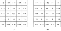
STEP2501で設定したRGBの7×7領域に対して、エッジ強調フィルタを掛けた際の注目画素値と掛ける前の注目画素値との差分(エッジ強調量)を各色毎に算出する。本実施の形態では、注目画素を中心として5×5エッジ強調フィルタを掛ける例で説明をするが、STEP2501で設定した処理領域サイズ以下のフィルタサイズであればよく、フィルタ係数値も適宜設定すればよい。図21(a)は5×5エッジ強調フィルタのフィルタ係数の一例である。注目画素値をN0とし、図21(a)のフィルタを掛けた結果の注目画素値をN1とし、エッジ強調量をΔFとすると、ΔFは式(24)を使って算出できる。
ΔF = N1−N0 ・・・式(24)
また、注目画素のフィルタ係数を図21(b)のように、図21(a)の注目画素位置のフィルタ係数から図21(a)のフィルタ合計値を引いた値とすることで、図21(b)を適用するだけでΔFを算出することができる。
<Correction Processing STEP 2701: Edge Enhancement Amount Calculation>
The difference (edge enhancement amount) between the pixel value of interest when the edge enhancement filter is applied to the pixel value of interest before being applied to the 7 × 7 RGB region set in STEP 2501 is calculated for each color. In this embodiment, an example in which a 5 × 5 edge enhancement filter is applied centering on the target pixel will be described. However, the filter size may be smaller than the processing region size set in STEP 2501, and the filter coefficient value may be set as appropriate. Good. FIG. 21A shows an example of the filter coefficient of the 5 × 5 edge enhancement filter. If the target pixel value is N0, the target pixel value obtained by applying the filter of FIG. 21A is N1, and the edge enhancement amount is ΔF, ΔF can be calculated using equation (24).
ΔF = N1-N0 (24)
Further, as shown in FIG. 21B, the filter coefficient of the target pixel is set to a value obtained by subtracting the filter total value in FIG. 21A from the filter coefficient at the target pixel position in FIG. ΔF can be calculated simply by applying (b).
<補正処理STEP2702:Fz1によるエッジ強調量補正>
STEP2701で算出したエッジ強調量ΔFをSTEP2507で設定したフィルタ強度Fz1で補正する。補正したエッジ強調量ΔFz1は式(25)を使って算出する。
ΔFz1 = Fz1×ΔF ・・・式(25)
STEP2702によって、変動回数が少ない文字に対しては比較的強くエッジ強調し、変動回数が多い網点に対しては比較的弱くエッジ強調を施すことが可能で、文字のシャープ感を増加することとモアレを強調しないことを両立することができる。
<Correction Processing STEP 2702: Edge Enhancement Amount Correction by Fz1>
The edge enhancement amount ΔF calculated in STEP 2701 is corrected with the filter strength Fz1 set in STEP 2507. The corrected edge enhancement amount ΔFz1 is calculated using Expression (25).
ΔFz1 = Fz1 × ΔF Equation (25)
According to STEP 2702, it is possible to perform edge enhancement relatively strongly for characters with a small number of fluctuations, and relatively weak edge enhancement for halftone dots with a large number of fluctuations, thereby increasing the sharpness of the characters. It is possible to balance not emphasizing moiré.
<補正処理STEP2703:Fz2によるエッジ強調量補正>
STEP2702で算出したエッジ強調量ΔFz1をSTEP2508で設定したフィルタ強度Fz2で補正する。補正したエッジ強調量ΔFz2は式(26)を使って算出する。
ΔFz2 = Fz2×ΔFz1 ・・・式(26)
図12(b)のようにFz2を設定した場合、STEP2703によって、太線は縁取りがでないようエッジ強調が施され、細線は太線より強くエッジ強調してシャープ感の増加と黒文字の濃度増加を施すことができる。
<Correction Processing STEP 2703: Edge Enhancement Amount Correction by Fz2>
The edge enhancement amount ΔFz1 calculated in STEP 2702 is corrected with the filter strength Fz2 set in STEP 2508. The corrected edge enhancement amount ΔFz2 is calculated using Expression (26).
ΔFz2 = Fz2 × ΔFz1 (26)
When Fz2 is set as shown in FIG. 12B, in STEP2703, edge emphasis is applied so that the thick line is not outlined, and the fine line is edge-enhanced stronger than the thick line to increase sharpness and increase the density of black characters. Can do.
<補正処理STEP2704:Feによるエッジ強調量補正>
STEP2703で算出したエッジ強調量ΔFz2をSTEP2509で設定したフィルタ強度Feで補正する。補正したエッジ強調量ΔFeは式(27)を使って算出する。
ΔFe = Fe×ΔFz2 ・・・式(27)
STEP2704によって、文字のようなエッジ部は比較的強くエッジ強調し、背景や写真のような平坦部は比較的弱くエッジ強調を施すことができる。これにより文字のシャープ感増加とモアレを強調しないこと、写真を荒らさないことを両立できる。
<Correction Processing STEP 2704: Edge Enhancement Correction by Fe>
The edge enhancement amount ΔFz2 calculated in STEP 2703 is corrected with the filter strength Fe set in STEP 2509. The corrected edge enhancement amount ΔFe is calculated using Expression (27).
ΔFe = Fe × ΔFz2 (27)
In STEP 2704, edge portions such as characters can be edge-enhanced relatively strongly, and flat portions such as backgrounds and photographs can be edge-enhanced relatively weakly. As a result, it is possible to achieve both an increase in the sharpness of the characters, no emphasis on moire and no roughening of the photograph.
<補正処理STEP2705:エッジ強調フィルタ処理完了>
STEP2704で算出したエッジ強調量ΔFeを式(28)に示すように注目画素値N0に加算することによって、エッジ強調フィルタ処理画素値Neを算出する。
Ne = N0+ΔFe ・・・式(28)
尚、Neを所望のレンジにクリップする処理を入れてもよい。
<Correction Processing STEP 2705: Edge Enhancement Filter Processing Complete>
The edge enhancement filter processing pixel value Ne is calculated by adding the edge enhancement amount ΔFe calculated in STEP 2704 to the target pixel value N0 as shown in Expression (28).
Ne = N0 + ΔFe (28)
In addition, you may put the process which clips Ne to a desired range.
<補正処理STEP2706:置換量算出>
STEP2512で判定した置換画素位置の画素値を用いて置換量を算出する。STEP2501で設定したRGBの7×7領域からSTEP2512で判定した置換画素位置のRGB値を抽出する。注目画素値をN0とし、置換画素位置の画素値をC0とし、置換量をΔCとすると、ΔCは式(19)を使って算出できる。
ΔC = C0−N0 ・・・式(19)
<Correction Process STEP 2706: Calculation of Replacement Amount>
The replacement amount is calculated using the pixel value at the replacement pixel position determined in STEP2512. The RGB value at the replacement pixel position determined in STEP 2512 is extracted from the RGB 7 × 7 region set in STEP 2501. If the target pixel value is N0, the pixel value at the replacement pixel position is C0, and the replacement amount is ΔC, ΔC can be calculated using Equation (19).
ΔC = C0−N0 (19)
<補正処理STEP2707:Clによる置換量補正>
STEP2706で算出した置換量ΔCをSTEP2513で設定した置換強度Clで補正する。補正した置換量ΔClは式(20)を使って算出する。
ΔCl = Cl×ΔC ・・・式(20)
STEP2707によって、ジャギー発生を抑えた置換が施される。
<Correction Process STEP 2707: Correction of Replacement Amount by Cl>
The replacement amount ΔC calculated in STEP 2706 is corrected by the replacement intensity Cl set in STEP 2513. The corrected replacement amount ΔCl is calculated using the equation (20).
ΔCl = Cl × ΔC (20)
In STEP 2707, replacement with reduced jaggies is performed.
<補正処理STEP2708:Czによる置換量補正>
STEP2707で算出した置換量ΔClをSTEP2514で設定した置換強度Czで補正する。補正した置換量ΔCzは式(21)を使って算出する。
ΔCz = Cz×ΔCl ・・・式(21)
STEP2708によって、太線は置換を強くし、細線は置換を弱くしてジャギー発生を抑えた置換を施すことができる。
<Correction Process STEP 2708: Replacement Amount Correction by Cz>
The replacement amount ΔCl calculated in STEP 2707 is corrected with the replacement intensity Cz set in STEP 2514. The corrected replacement amount ΔCz is calculated using equation (21).
ΔCz = Cz × ΔCl (21)
According to STEP 2708, the thick line can be replaced more strongly, and the thin line can be replaced more weakly to suppress the occurrence of jaggies.
<補正処理STEP2709:Ceによる置換量補正>
STEP2708で算出した置換量ΔCzをSTEP2515で設定した置換強度Ceで補正する。補正した置換量ΔCeは式(22)を使って算出する。
ΔCe = Ce×ΔCz ・・・式(22)
STEP2709によって、文字等のエッジ部は比較的強く置換することでシャープ感を向上し、平坦部は比較的弱く置換することで荒れを防止する。
<Correction Process STEP 2709: Correction of Replacement Amount by Ce>
The replacement amount ΔCz calculated in STEP 2708 is corrected with the replacement strength Ce set in STEP 2515. The corrected replacement amount ΔCe is calculated using equation (22).
ΔCe = Ce × ΔCz Expression (22)
According to STEP 2709, sharpness is improved by replacing edge portions of characters and the like relatively strongly, and roughening is prevented by replacing flat portions relatively weakly.
<補正処理STEP2710:置換処理完了>
STEP2709で算出した置換量ΔCeを式(23)に示すように注目画素のエッジ強調フィルタ値Neに加算することによって、本発明によるフィルタと置換によるエッジ強調した注目画素値Ncを算出する。
Nc = Ne+ΔCe ・・・式(23)
尚、Ncを所望のレンジにクリップする処理を入れてもよい。
<Correction Processing STEP 2710: Completion of Replacement Processing>
By adding the replacement amount ΔCe calculated in STEP 2709 to the edge emphasis filter value Ne of the target pixel as shown in Expression (23), the target pixel value Nc with edge enhancement by the filter and replacement according to the present invention is calculated.
Nc = Ne + ΔCe (23)
In addition, you may put the process which clips Nc to a desired range.
<実施の形態による効果>
本実施形態によれば、置換を用いて強調を行なうことで、エッジをたたせつつ、縁取りのない強調を実行できる。
<Effects of the embodiment>
According to the present embodiment, by performing emphasis using replacement, emphasis without bordering can be performed while applying an edge.
また、代表値の一次微分からエッジ方向を決めるため、常に正しいエッジ方向から置換候補画素を選択でき、エッジ強調が効果的に実行できる。また、二次微分の符号を使って置換画素位置を決定するため、周囲の輝度値Lに応じて適切な輝度の画素が選択でき、エッジ強調が効果的に実行できる。また、二次微分が0の場合に前後の画素の二次微分値を参照して置換候補画素位置を決定するため、エッジ強調が効果的に実行できる。また、4方向からエッジ方向を決定するため、4方向以外の画素を参照する必要がなく、処理が簡単になる。またこの効果は参照領域が大きいほど顕著に表れる。 Further, since the edge direction is determined from the primary differentiation of the representative value, the replacement candidate pixel can always be selected from the correct edge direction, and edge enhancement can be effectively performed. Further, since the replacement pixel position is determined using the sign of the second derivative, a pixel having an appropriate luminance can be selected according to the surrounding luminance value L, and edge enhancement can be effectively performed. Further, when the secondary differentiation is 0, the replacement candidate pixel position is determined with reference to the secondary differential values of the preceding and succeeding pixels, so that edge enhancement can be effectively performed. Further, since the edge direction is determined from the four directions, it is not necessary to refer to pixels other than the four directions, and the processing becomes simple. This effect becomes more prominent as the reference area is larger.
図20に表したように7x7では参照領域49画素に対して4方向に含まれる画素は25画素であるが、9x9では81画素に対して33画素、11x11では121画素に対して41画素である。つまり参照画素が(2n+1)x(2n+1)の場合、参照領域の画素数は(2n+1)x(2n+1)に対して、4方向に含まれる画素は(8n+1)であり、nが大きくなるほど4方向以外の画素を参照しないことによる処理の簡略化の効果が大きい。同じ光学系を使用して読み取りを行なう場合、解像度を高くするほどエッジのぼけ量が大きくなることが多いことから、参照領域を大きくする必要ある。よってこの効果は、高解像度を対象とする場合ほど効果が大きい。また、エッジ方向を決定してからエッジ方向のみの変動加速度を求めるため、エッジ方向以外の変動加速度を求める必要がなく、処理が簡単になる。 As shown in FIG. 20, in 7 × 7, 25 pixels are included in four directions with respect to the reference region 49 pixels, but 9 × 9 has 33 pixels for 81 pixels and 11 × 11 has 41 pixels for 121 pixels. . That is, when the reference pixel is (2n + 1) x (2n + 1), the number of pixels in the reference region is (8n + 1) with respect to (2n + 1) x (2n + 1), and the larger the n, the more the four directions The effect of simplification of processing by not referring to other pixels is great. When reading is performed using the same optical system, the amount of blurring of the edge often increases as the resolution is increased, and thus it is necessary to increase the reference area. Therefore, this effect is more effective as the target is high resolution. In addition, since the fluctuation acceleration only in the edge direction is obtained after the edge direction is determined, it is not necessary to obtain the fluctuation acceleration other than in the edge direction, and the processing becomes simple.
また、次のような効果もある。図17は左側が青色、右側が黄色のグラデーションになっている画像を現している。一つ一つの四角は画素をあらわし、その中の3つの数字がそれぞれR,G,Bの信号値を表している。例えば0,0,240はR=0、G=0、B=240という意味であり、青色の画素を示している。左側の青色から右側の黄色までの中間部分が、青色から黄色の中間色になっており、これは光学系的読み取りによってぼけている状態を模式的にあらわしたものである。 There are also the following effects. FIG. 17 shows an image with a blue gradation on the left side and a yellow gradation on the right side. Each square represents a pixel, and three numbers therein represent R, G, and B signal values, respectively. For example, 0, 0, and 240 mean R = 0, G = 0, and B = 240, and indicate blue pixels. The middle part from the blue on the left side to the yellow on the right side is an intermediate color from blue to yellow, and this is a schematic representation of a state blurred by optical system reading.
この画像に補正強度は常にCl=Cz=Ce=1として、本実施の形態を適用したものを図18に示す。左側が青色、右側が黄色になっており、中間色部分がなくなっている。これは、光学的読み取りによって生じたぼけが補正され、シャープ感が向上していることがわかる。 FIG. 18 shows a case where the correction strength is always set to Cl = Cz = Ce = 1 and this embodiment is applied to this image. The left side is blue and the right side is yellow. This shows that the blur caused by optical reading is corrected and the sharpness is improved.
次に補正強度は常にCl=Cz=Ce=1として、L信号を作成せずに、R信号、G信号、B信号にそれぞれ独立に置換画素位置の決定と置換を実行したものを図19に示す。左側が青色、右側が黄色になっているが、その中間部分にR=0,G=0,B=0、すなわち黒い部分が生じている。これはR,G,Bそれぞれに置換画素位置を決定したことによっておこる問題であって、本実施の形態のように輝度Lを算出してそれをもとに共通の置換画素位置を決定することによって解決できる。 Next, the correction intensity is always set to Cl = Cz = Ce = 1, and the L pixel, the G signal, and the B signal are determined and replaced independently for the R signal, the G signal, and the B signal without creating the L signal in FIG. Show. Although the left side is blue and the right side is yellow, R = 0, G = 0, B = 0, that is, a black portion is generated in the middle portion. This is a problem caused by determining the replacement pixel position for each of R, G, and B. The luminance L is calculated as in the present embodiment, and a common replacement pixel position is determined based on the calculated luminance L. Can be solved by.
以上のように、本実施の形態においては、STEP2501においてRGB信号から輝度Lを作成し、輝度Lに基づいてSTEP2512において、置換画素位置を決定する。これによって、RGBの各信号値の信号分布形状によらず、常にRGB共通のただ一箇所の置換画素位置が決定できる。このことによって、RGB信号ごとに別々の置換画素位置を定めることによる、色ずれが生じるという問題を起こすことのない補正が可能になる。 As described above, in this embodiment, the luminance L is created from the RGB signals in STEP 2501, and the replacement pixel position is determined in STEP 2512 based on the luminance L. Thus, only one replacement pixel position common to RGB can be determined regardless of the signal distribution shape of each RGB signal value. As a result, it is possible to perform correction without causing a problem of color misregistration by determining different replacement pixel positions for each RGB signal.
また本実施の形態のL信号を用いずに、G信号をL信号とした場合でも同様にRGB共通のただ一箇所の置換画素位置を決定できるのは明らかであり、色ずれが生じるという問題を起こすことのない補正が可能になる。 Further, even when the G signal is set to the L signal without using the L signal of the present embodiment, it is clear that only one replacement pixel position common to RGB can be determined, and there is a problem that color misregistration occurs. Corrections that do not occur are possible.
また本実施形態には、カラー画像に対して、置換候補画素に対する置換強度を連続的に変化させることにより、自然画の階調を維持でき、また文字の強調量を強く、網点の強調量を弱くすることでモアレのない、より好適な結果を得ることができる。 In the present embodiment, the tone of the natural image can be maintained by continuously changing the replacement intensity for the replacement candidate pixel with respect to the color image, the emphasis amount of the character is increased, and the emphasis amount of the halftone dot is increased. By reducing the value, a more favorable result without moire can be obtained.
代表値信号を用いずに個別にエッジ方向を検出した場合、RGBそれぞれで別のエッジ方向が検出される場合がある。この場合、RGBそれぞれで別々の置換画素位置を選択することがあるだけでなく、Grd、LapもRGBごとに それぞれ計算する必要がある。本実施形態を用いることで、Grd,Lapは代表値信号に対して一度だけ求めればよくRGB別々に求めるよりも処理が簡単になる。 When edge directions are individually detected without using a representative value signal, different edge directions may be detected for each of RGB. In this case, it is necessary not only to select different replacement pixel positions for RGB but also to calculate Grd and Lap for each RGB. By using this embodiment, Grd and Lap need only be obtained once for the representative value signal, and the processing is simpler than obtaining separately for RGB.
以上のように、本実施の形態では代表値信号からエッジ方向を検出するため、かならず同じ方向のエッジが検出できる。またそれによって、計算量が少なくなり、処理が簡単になる。 As described above, in this embodiment, since the edge direction is detected from the representative value signal, the edge in the same direction can always be detected. This also reduces the amount of computation and simplifies processing.
(他の実施形態)
以上、本発明の実施形態について詳述したが、本発明は、複数の機器から構成されるシステムに適用しても良いし、また、一つの機器からなる装置に適用しても良い。
(Other embodiments)
Although the embodiments of the present invention have been described in detail above, the present invention may be applied to a system constituted by a plurality of devices or may be applied to an apparatus constituted by one device.
なお、本発明は、前述した実施形態の機能を実現するプログラムを、システム或いは装置に直接或いは遠隔から供給し、そのシステム或いは装置が、供給されたプログラムコードを読み出して実行することによっても達成される。従って、本発明の機能処理をコンピュータで実現するために、コンピュータにインストールされるプログラムコード自体も本発明の技術的範囲に含まれる。 The present invention can also be achieved by supplying a program that realizes the functions of the above-described embodiments directly or remotely to a system or apparatus, and the system or apparatus reads and executes the supplied program code. The Accordingly, the program code itself installed in the computer in order to realize the functional processing of the present invention by the computer is also included in the technical scope of the present invention.
その場合、プログラムの機能を有していれば、オブジェクトコード、インタプリタにより実行されるプログラム、OSに供給するスクリプトデータ等、プログラムの形態を問わない。 In this case, the program may be in any form as long as it has a program function, such as an object code, a program executed by an interpreter, or script data supplied to the OS.
プログラムを供給するための記録媒体としては、例えば、フロッピー(登録商標)ディスク、ハードディスク、光ディスク、光磁気ディスクがある。また、MO、CD−ROM、CD−R、CD−RW、磁気テープ、不揮発性のメモリカード、ROM、DVD(DVD−ROM,DVD−R)などがある。 Examples of the recording medium for supplying the program include a floppy (registered trademark) disk, a hard disk, an optical disk, and a magneto-optical disk. Further, there are MO, CD-ROM, CD-R, CD-RW, magnetic tape, nonvolatile memory card, ROM, DVD (DVD-ROM, DVD-R) and the like.
その他、クライアントPCのブラウザを用いてインターネットサイトに接続し、本発明に係るプログラムそのもの、もしくは更に自動インストール機能を含むファイルをハードディスク等の記録媒体にダウンロードするという利用方法もある。また、本発明に係るプログラムを構成するプログラムコードを複数のファイルに分割し、それぞれのファイルを異なるホームページからダウンロードすることによっても実現可能である。つまり、本発明の機能処理をコンピュータで実現するためのプログラムを複数のユーザに対してダウンロードさせるWWWサーバも、本発明の範疇に含まれる。 また、本発明に係るプログラムを暗号化してCD−ROM等の記憶媒体に格納してユーザに配布してもよい。所定の条件をクリアしたユーザに対し、インターネットを介してホームページから暗号化を解く鍵情報をダウンロードさせ、その鍵情報を使用することにより暗号化されたプログラムを実行してコンピュータにインストールさせて実現することも可能である。 In addition, there is a usage method in which a client PC browser is used to connect to an Internet site and a program according to the present invention itself or a file including an automatic installation function is downloaded to a recording medium such as a hard disk. It can also be realized by dividing the program code constituting the program according to the present invention into a plurality of files and downloading each file from a different homepage. That is, a WWW server that allows a plurality of users to download a program for realizing the functional processing of the present invention on a computer is also included in the scope of the present invention. Further, the program according to the present invention may be encrypted and stored in a storage medium such as a CD-ROM and distributed to users. This is realized by having a user who has cleared a predetermined condition download key information to be decrypted from a homepage via the Internet, execute the encrypted program by using the key information, and install it on a computer. It is also possible.
また、プログラムの指示に基づき、コンピュータ上で稼動しているOSなどが、実際の処理の一部または全部を行ない、その処理によっても前述した実施形態の機能が実現され得る。 Further, the functions of the above-described embodiments can be realized by performing part or all of the actual processing by the OS running on the computer based on the instructions of the program.
さらに、PCの機能拡張ユニットに備わるメモリに本発明に係るプログラムが書き込まれ、そのプログラムに基づき、その機能拡張ユニットに備わるCPUなどが実際の処理の一部または全部を行なう場合も、本発明の範疇に含まれる。 Furthermore, when the program according to the present invention is written in the memory provided in the function expansion unit of the PC and the CPU or the like provided in the function expansion unit performs part or all of the actual processing based on the program, Included in the category.
1 MFP
31 オートドキュメントフィーダ
13 プリントユニット
14 スキャニングユニット
15 オペレーションパネル
19 ディスプレイパネル
42 カードスロット
43 カメラポート
11 CPU
12 画像処理部
16 ROM
17 RAM
18 不揮発性RAM
19 ディスプレイユニット
20 センサユニット
21 ドライブユニット
22 カードインターフェイス
23 カメラインターフェイス
24 PCインターフェイス
1 MFP
31
12
17 RAM
18 Nonvolatile RAM
19
Claims (12)
処理対象画素を含む複数の画素に対応する画像領域を設定する設定手段と、
前記画像領域に含まれる画素毎に、前記複数色に対応した信号値から輝度値を生成する生成手段と、
前記画像領域に含まれる複数の画素間における、前記生成手段により生成された前記輝度値の相対的な大小関係に基づいて、前記処理対象画素の前記信号値と置換するための置換候補画素を、前記画像領域に含まれる複数の画素の中から決定する決定手段と、
前記処理対象画素の前記複数色に対応した信号値と、前記置換候補画素の前記複数色に対応した信号値とを用いて、前記処理対象画素の前記複数色に対応した信号値と前記置換候補画素の前記複数色に対応した信号値との間の値となるように、前記処理対象画素の信号値を置換するための置換信号値を算出する算出手段と、
前記算出手段により算出された前記置換信号値で、前記処理対象画素の信号値を置換する置換手段と、
を有することを特徴とする画像処理装置。 An image processing apparatus that performs correction processing for each of a plurality of pixels having signal values corresponding to a plurality of colors,
Setting means for setting an image region corresponding to a plurality of pixels including a processing target pixel;
For each pixel contained in the image area, and generate unit that generates a luminance value from the signal values corresponding to the plurality of colors,
A replacement candidate pixel for replacing the signal value of the processing target pixel based on the relative magnitude relationship of the luminance value generated by the generation unit between a plurality of pixels included in the image region , Determining means for determining from among a plurality of pixels included in the image region;
Using the signal value corresponding to the plurality of colors of the processing target pixel and the signal value corresponding to the plurality of colors of the replacement candidate pixel, the signal value corresponding to the plurality of colors of the processing target pixel and the replacement candidate Calculating means for calculating a replacement signal value for replacing the signal value of the processing target pixel so as to be a value between signal values corresponding to the plurality of colors of the pixel ;
Replacement means for replacing the signal value of the processing target pixel with the replacement signal value calculated by the calculation means ;
An image processing apparatus comprising:
処理対象画素を含む複数の画素に対応する画像領域を設定する設定工程と、
前記画像領域に含まれる画素毎に、前記複数色に対応した信号値から輝度値を生成する生成工程と、
前記画像領域に含まれる複数の画素間における、前記生成工程において生成された前記輝度値の相対的な大小関係に基づいて、前記処理対象画素の前記信号値と置換するための置換候補画素を、前記画像領域に含まれる複数の画素の中から決定する決定工程と、
前記処理対象画素の前記複数色に対応した信号値と、前記置換候補画素の前記複数色に対応した信号値とを用いて、前記処理対象画素の前記複数色に対応した信号値と前記置換候補画素の前記複数色に対応した信号値との間の値となるように、前記処理対象画素の信号値を置換するための置換信号値を算出する算出工程と、
前記算出工程において算出された前記置換信号値で、前記処理対象画素の信号値を置換する置換工程と、
を有することを特徴とする画像処理方法。 An image processing method executed in an image processing apparatus that performs correction processing for each of a plurality of pixels having signal values corresponding to a plurality of colors,
A setting step for setting an image region corresponding to a plurality of pixels including the processing target pixel;
For each pixel contained in the image area, and generate process that generates a luminance value from the signal values corresponding to the plurality of colors,
Based on the relative magnitude relationship of the luminance value generated in the generation step between a plurality of pixels included in the image region, replacement candidate pixels for replacement with the signal value of the processing target pixel, A determination step of determining from among a plurality of pixels included in the image region;
Using the signal value corresponding to the plurality of colors of the processing target pixel and the signal value corresponding to the plurality of colors of the replacement candidate pixel, the signal value corresponding to the plurality of colors of the processing target pixel and the replacement candidate A calculation step of calculating a replacement signal value for replacing the signal value of the processing target pixel so as to be a value between the signal values corresponding to the plurality of colors of the pixel ;
A replacement step of replacing the signal value of the processing target pixel with the replacement signal value calculated in the calculation step ;
An image processing method comprising:
Priority Applications (3)
| Application Number | Priority Date | Filing Date | Title |
|---|---|---|---|
| JP2006180379A JP4890974B2 (en) | 2006-06-29 | 2006-06-29 | Image processing apparatus and image processing method |
| US11/769,801 US7912280B2 (en) | 2006-06-29 | 2007-06-28 | Image processing apparatus, image processing method, and image processing program |
| US13/019,253 US8139849B2 (en) | 2006-06-29 | 2011-02-01 | Image processing apparatus, image processing method, and image processing program |
Applications Claiming Priority (1)
| Application Number | Priority Date | Filing Date | Title |
|---|---|---|---|
| JP2006180379A JP4890974B2 (en) | 2006-06-29 | 2006-06-29 | Image processing apparatus and image processing method |
Publications (3)
| Publication Number | Publication Date |
|---|---|
| JP2008011269A JP2008011269A (en) | 2008-01-17 |
| JP2008011269A5 JP2008011269A5 (en) | 2011-05-19 |
| JP4890974B2 true JP4890974B2 (en) | 2012-03-07 |
Family
ID=38876721
Family Applications (1)
| Application Number | Title | Priority Date | Filing Date |
|---|---|---|---|
| JP2006180379A Expired - Fee Related JP4890974B2 (en) | 2006-06-29 | 2006-06-29 | Image processing apparatus and image processing method |
Country Status (2)
| Country | Link |
|---|---|
| US (2) | US7912280B2 (en) |
| JP (1) | JP4890974B2 (en) |
Families Citing this family (21)
| Publication number | Priority date | Publication date | Assignee | Title |
|---|---|---|---|---|
| JP4926568B2 (en) * | 2006-06-29 | 2012-05-09 | キヤノン株式会社 | Image processing apparatus, image processing method, and image processing program |
| JP4890973B2 (en) | 2006-06-29 | 2012-03-07 | キヤノン株式会社 | Image processing apparatus, image processing method, image processing program, and storage medium |
| JP4872508B2 (en) * | 2006-07-28 | 2012-02-08 | ソニー株式会社 | Image processing apparatus, image processing method, and program |
| JP4878572B2 (en) | 2007-03-30 | 2012-02-15 | キヤノン株式会社 | Image processing apparatus and image processing method |
| JP4883789B2 (en) * | 2007-03-30 | 2012-02-22 | キヤノン株式会社 | Image processing apparatus and image processing method |
| JP4891130B2 (en) * | 2007-03-30 | 2012-03-07 | キヤノン株式会社 | Image processing apparatus and image processing method |
| JP5210145B2 (en) * | 2008-12-22 | 2013-06-12 | キヤノン株式会社 | Image processing method and image processing apparatus |
| EP2569931A1 (en) * | 2010-05-10 | 2013-03-20 | OCE-Technologies B.V. | Method to restore edges in rasterized images |
| US9623671B2 (en) | 2010-05-24 | 2017-04-18 | Canon Kabushiki Kaisha | Image processor, printing apparatus, and image processing method |
| JP5479219B2 (en) | 2010-05-24 | 2014-04-23 | キヤノン株式会社 | Image processing apparatus and image processing method |
| US9694598B2 (en) | 2010-05-24 | 2017-07-04 | Canon Kabushiki Kaisha | Image processing apparatus, ink jet printing apparatus, and image processing method |
| JP5436389B2 (en) | 2010-10-05 | 2014-03-05 | キヤノン株式会社 | Image processing apparatus and image processing method |
| JP5541721B2 (en) | 2010-10-05 | 2014-07-09 | キヤノン株式会社 | Image processing apparatus and image processing method |
| JP5436388B2 (en) | 2010-10-05 | 2014-03-05 | キヤノン株式会社 | Image processing apparatus, image processing method, and image recording apparatus |
| JP5465145B2 (en) | 2010-10-05 | 2014-04-09 | キヤノン株式会社 | Image processing apparatus, image processing method, and image recording apparatus |
| TWI466063B (en) * | 2011-09-29 | 2014-12-21 | Altek Corp | Processing method for image interpolation |
| JP6234098B2 (en) | 2013-07-19 | 2017-11-22 | キヤノン株式会社 | Image processing apparatus, image processing method, and program |
| JP6821418B2 (en) | 2016-12-16 | 2021-01-27 | キヤノン株式会社 | Image processing equipment, image processing methods, and programs |
| JP7114910B2 (en) * | 2018-01-25 | 2022-08-09 | ブラザー工業株式会社 | Image reader |
| JP7433918B2 (en) * | 2020-01-09 | 2024-02-20 | キヤノン株式会社 | Image processing device and image processing method |
| KR20230055361A (en) | 2021-10-18 | 2023-04-25 | 캐논 가부시끼가이샤 | Image processing apparatus, image processing method, and storage medium storing program |
Family Cites Families (63)
| Publication number | Priority date | Publication date | Assignee | Title |
|---|---|---|---|---|
| US193679A (en) * | 1877-07-31 | Improvement in automatic tubular car-couplings | ||
| ATE21882T1 (en) | 1982-02-23 | 1986-09-15 | Dharamsi Morarji Chem Co | PROCESS FOR THE PRODUCTION OF PHOSPHORIC ACID AND GYPSUM IN COMMERCIAL FORM FROM PHOSPHATE ROCK. |
| US4577235A (en) | 1984-08-20 | 1986-03-18 | The Mead Corporation | Text/continuous tone image decision processor |
| JP2702928B2 (en) | 1987-06-19 | 1998-01-26 | 株式会社日立製作所 | Image input device |
| JP2620368B2 (en) | 1989-04-18 | 1997-06-11 | 富士写真フイルム株式会社 | Image signal processing method and apparatus |
| US5045952A (en) | 1989-08-21 | 1991-09-03 | Xerox Corporation | Method for edge enhanced error diffusion |
| EP0415648B1 (en) | 1989-08-31 | 1998-05-20 | Canon Kabushiki Kaisha | Image processing apparatus |
| JPH03215768A (en) | 1990-01-19 | 1991-09-20 | Hitachi Metals Ltd | Magnetic sensor |
| JP3184512B2 (en) * | 1990-06-20 | 2001-07-09 | キャノン株式会社 | Image processing apparatus and image processing method |
| US5394250A (en) * | 1991-03-10 | 1995-02-28 | Canon Kabushiki Kaisha | Image processing capable of handling multi-level image data without deterioration of image quality in highlight areas |
| EP0555674B1 (en) * | 1992-02-11 | 1999-04-21 | Eastman Kodak Company | Image rendering system and associated method for minimizing contours in a quantized digital color image |
| DE4232704C2 (en) * | 1992-09-30 | 1995-04-20 | Hell Ag Linotype | Method and circuit arrangement for the electronic retouching of images |
| US5960109A (en) * | 1993-09-07 | 1999-09-28 | Xerox Corporation | Single pass marker enclosed area detection system and method for a photocopier |
| US5717789A (en) * | 1993-09-08 | 1998-02-10 | California Institute Of Technology | Image enhancement by non-linear extrapolation in frequency space |
| US5914731A (en) | 1993-09-30 | 1999-06-22 | Canon Kabushiki Kaisha | Data recording using randomized variations to prevent visual artifacts due to non-uniformities in a printing apparatus |
| US6075894A (en) | 1993-11-30 | 2000-06-13 | Canon Kabushiki Kaisha | High-quality edge-smoothing based upon a determination of consecutive black dots |
| JP3215768B2 (en) | 1994-03-24 | 2001-10-09 | 株式会社東芝 | Image processing device |
| US5621868A (en) * | 1994-04-15 | 1997-04-15 | Sony Corporation | Generating imitation custom artwork by simulating brush strokes and enhancing edges |
| US5585944A (en) * | 1994-05-10 | 1996-12-17 | Kaleida Labs, Inc. | Method for compressing and decompressing images by subdividing pixel color distributions |
| US6714689B1 (en) | 1995-09-29 | 2004-03-30 | Canon Kabushiki Kaisha | Image synthesizing method |
| US6292621B1 (en) | 1996-02-05 | 2001-09-18 | Canon Kabushiki Kaisha | Recording apparatus for newly recording a second encoded data train on a recording medium on which an encoded data train is recorded |
| US5778158A (en) * | 1996-03-04 | 1998-07-07 | Hewlett-Packard Company | High speed system for image scaling |
| JPH1013697A (en) | 1996-06-18 | 1998-01-16 | Canon Inc | Image processor and image processing method |
| JP3755854B2 (en) | 1997-04-07 | 2006-03-15 | 理想科学工業株式会社 | Image processing apparatus and two-dimensional line feature amount calculation apparatus |
| US6075926A (en) * | 1997-04-21 | 2000-06-13 | Hewlett-Packard Company | Computerized method for improving data resolution |
| JP3472094B2 (en) | 1997-08-21 | 2003-12-02 | シャープ株式会社 | Area judgment device |
| US6480624B1 (en) * | 1997-09-30 | 2002-11-12 | Minolta Co., Ltd. | Color discrimination apparatus and method |
| DE69939055D1 (en) | 1998-03-05 | 2008-08-21 | Matsushita Electric Ind Co Ltd | PICTURE CODING METHOD, PICTURE ENCODING / DECODING METHOD, IMAGE CODING OR PICTURE RECORDING / REPRODUCTION DEVICE |
| JP3492202B2 (en) | 1998-06-24 | 2004-02-03 | キヤノン株式会社 | Image processing method, apparatus and recording medium |
| US6694051B1 (en) | 1998-06-24 | 2004-02-17 | Canon Kabushiki Kaisha | Image processing method, image processing apparatus and recording medium |
| US6278434B1 (en) * | 1998-10-07 | 2001-08-21 | Microsoft Corporation | Non-square scaling of image data to be mapped to pixel sub-components |
| EP1006482A3 (en) * | 1998-12-01 | 2005-08-10 | Canon Kabushiki Kaisha | Encoding separately image object and its boundary |
| JP2000244773A (en) * | 1999-02-24 | 2000-09-08 | Canon Inc | Contour correcting device |
| JP4046465B2 (en) * | 1999-09-17 | 2008-02-13 | 株式会社リコー | Image processing apparatus, image processing method, and image processing system |
| US7289154B2 (en) * | 2000-05-10 | 2007-10-30 | Eastman Kodak Company | Digital image processing method and apparatus for brightness adjustment of digital images |
| US6636646B1 (en) * | 2000-07-20 | 2003-10-21 | Eastman Kodak Company | Digital image processing method and for brightness adjustment of digital images |
| JP2002077623A (en) | 2000-08-25 | 2002-03-15 | Ricoh Co Ltd | Image processing apparatus |
| US6856704B1 (en) * | 2000-09-13 | 2005-02-15 | Eastman Kodak Company | Method for enhancing a digital image based upon pixel color |
| JP2002262124A (en) | 2000-11-30 | 2002-09-13 | Canon Inc | Image processor and method, and recording control method and device and printer driver |
| US6934412B2 (en) * | 2000-12-15 | 2005-08-23 | Xerox Corporation | Detecting small amounts of color in an image |
| JP2002209223A (en) * | 2001-01-09 | 2002-07-26 | Sony Corp | Image processing unit and method, and recording medium |
| US7251056B2 (en) | 2001-06-11 | 2007-07-31 | Ricoh Company, Ltd. | Image processing apparatus, image processing method and information recording medium |
| US7466319B1 (en) * | 2002-01-08 | 2008-12-16 | 3Dlabs | System and method for fast gradient pixel clears in graphics rendering |
| JP4011933B2 (en) | 2002-02-22 | 2007-11-21 | キヤノン株式会社 | Image processing apparatus and method |
| JP2003283873A (en) | 2002-03-20 | 2003-10-03 | Sanyo Electric Co Ltd | Contour enhancement circuit |
| JP3943981B2 (en) | 2002-04-10 | 2007-07-11 | キヤノン株式会社 | Image processing apparatus and method |
| US7622117B2 (en) | 2002-04-17 | 2009-11-24 | Dynamis Therapeutics, Inc. | 3-deoxyglucosone and skin |
| US8102558B2 (en) | 2002-08-05 | 2012-01-24 | Canon Kabushiki Kaisha | Image supply apparatus, control method therefor, and printing system |
| US7280703B2 (en) * | 2002-11-14 | 2007-10-09 | Eastman Kodak Company | Method of spatially filtering a digital image using chrominance information |
| US7432985B2 (en) | 2003-03-26 | 2008-10-07 | Canon Kabushiki Kaisha | Image processing method |
| KR100513784B1 (en) | 2004-01-15 | 2005-09-09 | 삼성전자주식회사 | The method and device of improving image |
| JP4831941B2 (en) | 2004-06-08 | 2011-12-07 | オリンパス株式会社 | Imaging processing system, program, and storage medium |
| US7308137B2 (en) * | 2004-06-08 | 2007-12-11 | Benq Corporation | Method of determining color composition of an image |
| US7570810B2 (en) * | 2005-02-24 | 2009-08-04 | Seiko Epson Corporation | Method and apparatus applying digital image filtering to color filter array data |
| US7426312B2 (en) * | 2005-07-05 | 2008-09-16 | Xerox Corporation | Contrast enhancement of images |
| JP4375322B2 (en) * | 2005-11-04 | 2009-12-02 | オムロン株式会社 | Image processing apparatus, image processing method, program thereof, and computer-readable recording medium recording the program |
| JP4926568B2 (en) | 2006-06-29 | 2012-05-09 | キヤノン株式会社 | Image processing apparatus, image processing method, and image processing program |
| JP4890973B2 (en) | 2006-06-29 | 2012-03-07 | キヤノン株式会社 | Image processing apparatus, image processing method, image processing program, and storage medium |
| JP4637063B2 (en) | 2006-07-04 | 2011-02-23 | キヤノン株式会社 | Image processing apparatus, image processing method, and program |
| JP4684959B2 (en) | 2006-07-04 | 2011-05-18 | キヤノン株式会社 | Image processing apparatus, image processing method, and program |
| JP4632452B2 (en) | 2006-07-07 | 2011-02-16 | キヤノン株式会社 | Image correction processing apparatus, image correction processing method, program, and storage medium |
| JP4683654B2 (en) | 2006-07-07 | 2011-05-18 | キヤノン株式会社 | Image processing apparatus, image processing apparatus control method, and program |
| KR20080006112A (en) | 2006-07-11 | 2008-01-16 | 삼성전자주식회사 | Halftoning method and apparatus to improve sharpness in boundary region |
-
2006
- 2006-06-29 JP JP2006180379A patent/JP4890974B2/en not_active Expired - Fee Related
-
2007
- 2007-06-28 US US11/769,801 patent/US7912280B2/en not_active Expired - Fee Related
-
2011
- 2011-02-01 US US13/019,253 patent/US8139849B2/en not_active Expired - Fee Related
Also Published As
| Publication number | Publication date |
|---|---|
| US8139849B2 (en) | 2012-03-20 |
| JP2008011269A (en) | 2008-01-17 |
| US20080002901A1 (en) | 2008-01-03 |
| US7912280B2 (en) | 2011-03-22 |
| US20110135201A1 (en) | 2011-06-09 |
Similar Documents
| Publication | Publication Date | Title |
|---|---|---|
| JP4890974B2 (en) | Image processing apparatus and image processing method | |
| JP4926568B2 (en) | Image processing apparatus, image processing method, and image processing program | |
| JP4632452B2 (en) | Image correction processing apparatus, image correction processing method, program, and storage medium | |
| JP4637063B2 (en) | Image processing apparatus, image processing method, and program | |
| JP4684959B2 (en) | Image processing apparatus, image processing method, and program | |
| JP4890973B2 (en) | Image processing apparatus, image processing method, image processing program, and storage medium | |
| WO2008004710A1 (en) | Image processing device, image processing method, and image processing program | |
| US8441701B2 (en) | Image processing apparatus, image processing method, image processing program, and storage medium | |
| JP4402090B2 (en) | Image forming apparatus, image forming method, program, and recording medium | |
| JP2010016628A (en) | Image processing device and image processing method | |
| JP5058695B2 (en) | Image processing apparatus, image processing method, and image processing program | |
| JP2009089266A (en) | Image processing device and pixel attribute identification method | |
| JP2008205967A (en) | Image processor | |
| JP4084537B2 (en) | Image processing apparatus, image processing method, recording medium, and image forming apparatus | |
| JP5057598B2 (en) | Image processing apparatus, image processing method, image processing program, and storage medium | |
| JP2014060681A (en) | Image processor, program, and image forming apparatus | |
| JP2010283416A (en) | Image processing apparatus, printing system, image processing method and computer program |
Legal Events
| Date | Code | Title | Description |
|---|---|---|---|
| A621 | Written request for application examination |
Free format text: JAPANESE INTERMEDIATE CODE: A621 Effective date: 20090629 |
|
| A521 | Request for written amendment filed |
Free format text: JAPANESE INTERMEDIATE CODE: A523 Effective date: 20090813 |
|
| A521 | Request for written amendment filed |
Free format text: JAPANESE INTERMEDIATE CODE: A523 Effective date: 20110405 |
|
| A131 | Notification of reasons for refusal |
Free format text: JAPANESE INTERMEDIATE CODE: A131 Effective date: 20110922 |
|
| A521 | Request for written amendment filed |
Free format text: JAPANESE INTERMEDIATE CODE: A523 Effective date: 20111121 |
|
| TRDD | Decision of grant or rejection written | ||
| A01 | Written decision to grant a patent or to grant a registration (utility model) |
Free format text: JAPANESE INTERMEDIATE CODE: A01 Effective date: 20111212 |
|
| A01 | Written decision to grant a patent or to grant a registration (utility model) |
Free format text: JAPANESE INTERMEDIATE CODE: A01 |
|
| A61 | First payment of annual fees (during grant procedure) |
Free format text: JAPANESE INTERMEDIATE CODE: A61 Effective date: 20111215 |
|
| R151 | Written notification of patent or utility model registration |
Ref document number: 4890974 Country of ref document: JP Free format text: JAPANESE INTERMEDIATE CODE: R151 |
|
| FPAY | Renewal fee payment (event date is renewal date of database) |
Free format text: PAYMENT UNTIL: 20141222 Year of fee payment: 3 |
|
| LAPS | Cancellation because of no payment of annual fees |