JP4881991B2 - Electric vehicle oil temperature rise control method and apparatus, and electric vehicle - Google Patents
Electric vehicle oil temperature rise control method and apparatus, and electric vehicle Download PDFInfo
- Publication number
- JP4881991B2 JP4881991B2 JP2009245516A JP2009245516A JP4881991B2 JP 4881991 B2 JP4881991 B2 JP 4881991B2 JP 2009245516 A JP2009245516 A JP 2009245516A JP 2009245516 A JP2009245516 A JP 2009245516A JP 4881991 B2 JP4881991 B2 JP 4881991B2
- Authority
- JP
- Japan
- Prior art keywords
- current
- electric vehicle
- advance angle
- motor
- oil temperature
- Prior art date
- Legal status (The legal status is an assumption and is not a legal conclusion. Google has not performed a legal analysis and makes no representation as to the accuracy of the status listed.)
- Expired - Fee Related
Links
Images


Classifications
-
- F—MECHANICAL ENGINEERING; LIGHTING; HEATING; WEAPONS; BLASTING
- F16—ENGINEERING ELEMENTS AND UNITS; GENERAL MEASURES FOR PRODUCING AND MAINTAINING EFFECTIVE FUNCTIONING OF MACHINES OR INSTALLATIONS; THERMAL INSULATION IN GENERAL
- F16H—GEARING
- F16H57/00—General details of gearing
- F16H57/04—Features relating to lubrication or cooling or heating
- F16H57/0412—Cooling or heating; Control of temperature
- F16H57/0413—Controlled cooling or heating of lubricant; Temperature control therefor
-
- B—PERFORMING OPERATIONS; TRANSPORTING
- B60—VEHICLES IN GENERAL
- B60L—PROPULSION OF ELECTRICALLY-PROPELLED VEHICLES; SUPPLYING ELECTRIC POWER FOR AUXILIARY EQUIPMENT OF ELECTRICALLY-PROPELLED VEHICLES; ELECTRODYNAMIC BRAKE SYSTEMS FOR VEHICLES IN GENERAL; MAGNETIC SUSPENSION OR LEVITATION FOR VEHICLES; MONITORING OPERATING VARIABLES OF ELECTRICALLY-PROPELLED VEHICLES; ELECTRIC SAFETY DEVICES FOR ELECTRICALLY-PROPELLED VEHICLES
- B60L1/00—Supplying electric power to auxiliary equipment of vehicles
- B60L1/02—Supplying electric power to auxiliary equipment of vehicles to electric heating circuits
- B60L1/04—Supplying electric power to auxiliary equipment of vehicles to electric heating circuits fed by the power supply line
- B60L1/06—Supplying electric power to auxiliary equipment of vehicles to electric heating circuits fed by the power supply line using only one supply
-
- B—PERFORMING OPERATIONS; TRANSPORTING
- B60—VEHICLES IN GENERAL
- B60L—PROPULSION OF ELECTRICALLY-PROPELLED VEHICLES; SUPPLYING ELECTRIC POWER FOR AUXILIARY EQUIPMENT OF ELECTRICALLY-PROPELLED VEHICLES; ELECTRODYNAMIC BRAKE SYSTEMS FOR VEHICLES IN GENERAL; MAGNETIC SUSPENSION OR LEVITATION FOR VEHICLES; MONITORING OPERATING VARIABLES OF ELECTRICALLY-PROPELLED VEHICLES; ELECTRIC SAFETY DEVICES FOR ELECTRICALLY-PROPELLED VEHICLES
- B60L15/00—Methods, circuits, or devices for controlling the traction-motor speed of electrically-propelled vehicles
- B60L15/20—Methods, circuits, or devices for controlling the traction-motor speed of electrically-propelled vehicles for control of the vehicle or its driving motor to achieve a desired performance, e.g. speed, torque, programmed variation of speed
-
- B—PERFORMING OPERATIONS; TRANSPORTING
- B60—VEHICLES IN GENERAL
- B60L—PROPULSION OF ELECTRICALLY-PROPELLED VEHICLES; SUPPLYING ELECTRIC POWER FOR AUXILIARY EQUIPMENT OF ELECTRICALLY-PROPELLED VEHICLES; ELECTRODYNAMIC BRAKE SYSTEMS FOR VEHICLES IN GENERAL; MAGNETIC SUSPENSION OR LEVITATION FOR VEHICLES; MONITORING OPERATING VARIABLES OF ELECTRICALLY-PROPELLED VEHICLES; ELECTRIC SAFETY DEVICES FOR ELECTRICALLY-PROPELLED VEHICLES
- B60L3/00—Electric devices on electrically-propelled vehicles for safety purposes; Monitoring operating variables, e.g. speed, deceleration or energy consumption
- B60L3/0023—Detecting, eliminating, remedying or compensating for drive train abnormalities, e.g. failures within the drive train
- B60L3/0061—Detecting, eliminating, remedying or compensating for drive train abnormalities, e.g. failures within the drive train relating to electrical machines
-
- B—PERFORMING OPERATIONS; TRANSPORTING
- B60—VEHICLES IN GENERAL
- B60L—PROPULSION OF ELECTRICALLY-PROPELLED VEHICLES; SUPPLYING ELECTRIC POWER FOR AUXILIARY EQUIPMENT OF ELECTRICALLY-PROPELLED VEHICLES; ELECTRODYNAMIC BRAKE SYSTEMS FOR VEHICLES IN GENERAL; MAGNETIC SUSPENSION OR LEVITATION FOR VEHICLES; MONITORING OPERATING VARIABLES OF ELECTRICALLY-PROPELLED VEHICLES; ELECTRIC SAFETY DEVICES FOR ELECTRICALLY-PROPELLED VEHICLES
- B60L50/00—Electric propulsion with power supplied within the vehicle
- B60L50/50—Electric propulsion with power supplied within the vehicle using propulsion power supplied by batteries or fuel cells
- B60L50/51—Electric propulsion with power supplied within the vehicle using propulsion power supplied by batteries or fuel cells characterised by AC-motors
-
- B—PERFORMING OPERATIONS; TRANSPORTING
- B60—VEHICLES IN GENERAL
- B60L—PROPULSION OF ELECTRICALLY-PROPELLED VEHICLES; SUPPLYING ELECTRIC POWER FOR AUXILIARY EQUIPMENT OF ELECTRICALLY-PROPELLED VEHICLES; ELECTRODYNAMIC BRAKE SYSTEMS FOR VEHICLES IN GENERAL; MAGNETIC SUSPENSION OR LEVITATION FOR VEHICLES; MONITORING OPERATING VARIABLES OF ELECTRICALLY-PROPELLED VEHICLES; ELECTRIC SAFETY DEVICES FOR ELECTRICALLY-PROPELLED VEHICLES
- B60L53/00—Methods of charging batteries, specially adapted for electric vehicles; Charging stations or on-board charging equipment therefor; Exchange of energy storage elements in electric vehicles
- B60L53/10—Methods of charging batteries, specially adapted for electric vehicles; Charging stations or on-board charging equipment therefor; Exchange of energy storage elements in electric vehicles characterised by the energy transfer between the charging station and the vehicle
- B60L53/14—Conductive energy transfer
-
- B—PERFORMING OPERATIONS; TRANSPORTING
- B60—VEHICLES IN GENERAL
- B60L—PROPULSION OF ELECTRICALLY-PROPELLED VEHICLES; SUPPLYING ELECTRIC POWER FOR AUXILIARY EQUIPMENT OF ELECTRICALLY-PROPELLED VEHICLES; ELECTRODYNAMIC BRAKE SYSTEMS FOR VEHICLES IN GENERAL; MAGNETIC SUSPENSION OR LEVITATION FOR VEHICLES; MONITORING OPERATING VARIABLES OF ELECTRICALLY-PROPELLED VEHICLES; ELECTRIC SAFETY DEVICES FOR ELECTRICALLY-PROPELLED VEHICLES
- B60L53/00—Methods of charging batteries, specially adapted for electric vehicles; Charging stations or on-board charging equipment therefor; Exchange of energy storage elements in electric vehicles
- B60L53/30—Constructional details of charging stations
- B60L53/305—Communication interfaces
-
- H—ELECTRICITY
- H02—GENERATION; CONVERSION OR DISTRIBUTION OF ELECTRIC POWER
- H02P—CONTROL OR REGULATION OF ELECTRIC MOTORS, ELECTRIC GENERATORS OR DYNAMO-ELECTRIC CONVERTERS; CONTROLLING TRANSFORMERS, REACTORS OR CHOKE COILS
- H02P29/00—Arrangements for regulating or controlling electric motors, appropriate for both AC and DC motors
- H02P29/60—Controlling or determining the temperature of the motor or of the drive
- H02P29/62—Controlling or determining the temperature of the motor or of the drive for raising the temperature of the motor
-
- B—PERFORMING OPERATIONS; TRANSPORTING
- B60—VEHICLES IN GENERAL
- B60L—PROPULSION OF ELECTRICALLY-PROPELLED VEHICLES; SUPPLYING ELECTRIC POWER FOR AUXILIARY EQUIPMENT OF ELECTRICALLY-PROPELLED VEHICLES; ELECTRODYNAMIC BRAKE SYSTEMS FOR VEHICLES IN GENERAL; MAGNETIC SUSPENSION OR LEVITATION FOR VEHICLES; MONITORING OPERATING VARIABLES OF ELECTRICALLY-PROPELLED VEHICLES; ELECTRIC SAFETY DEVICES FOR ELECTRICALLY-PROPELLED VEHICLES
- B60L2240/00—Control parameters of input or output; Target parameters
- B60L2240/10—Vehicle control parameters
- B60L2240/36—Temperature of vehicle components or parts
-
- B—PERFORMING OPERATIONS; TRANSPORTING
- B60—VEHICLES IN GENERAL
- B60L—PROPULSION OF ELECTRICALLY-PROPELLED VEHICLES; SUPPLYING ELECTRIC POWER FOR AUXILIARY EQUIPMENT OF ELECTRICALLY-PROPELLED VEHICLES; ELECTRODYNAMIC BRAKE SYSTEMS FOR VEHICLES IN GENERAL; MAGNETIC SUSPENSION OR LEVITATION FOR VEHICLES; MONITORING OPERATING VARIABLES OF ELECTRICALLY-PROPELLED VEHICLES; ELECTRIC SAFETY DEVICES FOR ELECTRICALLY-PROPELLED VEHICLES
- B60L2250/00—Driver interactions
- B60L2250/10—Driver interactions by alarm
-
- F—MECHANICAL ENGINEERING; LIGHTING; HEATING; WEAPONS; BLASTING
- F16—ENGINEERING ELEMENTS AND UNITS; GENERAL MEASURES FOR PRODUCING AND MAINTAINING EFFECTIVE FUNCTIONING OF MACHINES OR INSTALLATIONS; THERMAL INSULATION IN GENERAL
- F16H—GEARING
- F16H57/00—General details of gearing
- F16H57/04—Features relating to lubrication or cooling or heating
- F16H57/0467—Elements of gearings to be lubricated, cooled or heated
- F16H57/0476—Electric machines and gearing, i.e. joint lubrication or cooling or heating thereof
-
- Y—GENERAL TAGGING OF NEW TECHNOLOGICAL DEVELOPMENTS; GENERAL TAGGING OF CROSS-SECTIONAL TECHNOLOGIES SPANNING OVER SEVERAL SECTIONS OF THE IPC; TECHNICAL SUBJECTS COVERED BY FORMER USPC CROSS-REFERENCE ART COLLECTIONS [XRACs] AND DIGESTS
- Y02—TECHNOLOGIES OR APPLICATIONS FOR MITIGATION OR ADAPTATION AGAINST CLIMATE CHANGE
- Y02T—CLIMATE CHANGE MITIGATION TECHNOLOGIES RELATED TO TRANSPORTATION
- Y02T10/00—Road transport of goods or passengers
- Y02T10/60—Other road transportation technologies with climate change mitigation effect
- Y02T10/64—Electric machine technologies in electromobility
-
- Y—GENERAL TAGGING OF NEW TECHNOLOGICAL DEVELOPMENTS; GENERAL TAGGING OF CROSS-SECTIONAL TECHNOLOGIES SPANNING OVER SEVERAL SECTIONS OF THE IPC; TECHNICAL SUBJECTS COVERED BY FORMER USPC CROSS-REFERENCE ART COLLECTIONS [XRACs] AND DIGESTS
- Y02—TECHNOLOGIES OR APPLICATIONS FOR MITIGATION OR ADAPTATION AGAINST CLIMATE CHANGE
- Y02T—CLIMATE CHANGE MITIGATION TECHNOLOGIES RELATED TO TRANSPORTATION
- Y02T10/00—Road transport of goods or passengers
- Y02T10/60—Other road transportation technologies with climate change mitigation effect
- Y02T10/70—Energy storage systems for electromobility, e.g. batteries
-
- Y—GENERAL TAGGING OF NEW TECHNOLOGICAL DEVELOPMENTS; GENERAL TAGGING OF CROSS-SECTIONAL TECHNOLOGIES SPANNING OVER SEVERAL SECTIONS OF THE IPC; TECHNICAL SUBJECTS COVERED BY FORMER USPC CROSS-REFERENCE ART COLLECTIONS [XRACs] AND DIGESTS
- Y02—TECHNOLOGIES OR APPLICATIONS FOR MITIGATION OR ADAPTATION AGAINST CLIMATE CHANGE
- Y02T—CLIMATE CHANGE MITIGATION TECHNOLOGIES RELATED TO TRANSPORTATION
- Y02T10/00—Road transport of goods or passengers
- Y02T10/60—Other road transportation technologies with climate change mitigation effect
- Y02T10/7072—Electromobility specific charging systems or methods for batteries, ultracapacitors, supercapacitors or double-layer capacitors
-
- Y—GENERAL TAGGING OF NEW TECHNOLOGICAL DEVELOPMENTS; GENERAL TAGGING OF CROSS-SECTIONAL TECHNOLOGIES SPANNING OVER SEVERAL SECTIONS OF THE IPC; TECHNICAL SUBJECTS COVERED BY FORMER USPC CROSS-REFERENCE ART COLLECTIONS [XRACs] AND DIGESTS
- Y02—TECHNOLOGIES OR APPLICATIONS FOR MITIGATION OR ADAPTATION AGAINST CLIMATE CHANGE
- Y02T—CLIMATE CHANGE MITIGATION TECHNOLOGIES RELATED TO TRANSPORTATION
- Y02T10/00—Road transport of goods or passengers
- Y02T10/60—Other road transportation technologies with climate change mitigation effect
- Y02T10/72—Electric energy management in electromobility
-
- Y—GENERAL TAGGING OF NEW TECHNOLOGICAL DEVELOPMENTS; GENERAL TAGGING OF CROSS-SECTIONAL TECHNOLOGIES SPANNING OVER SEVERAL SECTIONS OF THE IPC; TECHNICAL SUBJECTS COVERED BY FORMER USPC CROSS-REFERENCE ART COLLECTIONS [XRACs] AND DIGESTS
- Y02—TECHNOLOGIES OR APPLICATIONS FOR MITIGATION OR ADAPTATION AGAINST CLIMATE CHANGE
- Y02T—CLIMATE CHANGE MITIGATION TECHNOLOGIES RELATED TO TRANSPORTATION
- Y02T90/00—Enabling technologies or technologies with a potential or indirect contribution to GHG emissions mitigation
- Y02T90/10—Technologies relating to charging of electric vehicles
- Y02T90/12—Electric charging stations
-
- Y—GENERAL TAGGING OF NEW TECHNOLOGICAL DEVELOPMENTS; GENERAL TAGGING OF CROSS-SECTIONAL TECHNOLOGIES SPANNING OVER SEVERAL SECTIONS OF THE IPC; TECHNICAL SUBJECTS COVERED BY FORMER USPC CROSS-REFERENCE ART COLLECTIONS [XRACs] AND DIGESTS
- Y02—TECHNOLOGIES OR APPLICATIONS FOR MITIGATION OR ADAPTATION AGAINST CLIMATE CHANGE
- Y02T—CLIMATE CHANGE MITIGATION TECHNOLOGIES RELATED TO TRANSPORTATION
- Y02T90/00—Enabling technologies or technologies with a potential or indirect contribution to GHG emissions mitigation
- Y02T90/10—Technologies relating to charging of electric vehicles
- Y02T90/14—Plug-in electric vehicles
-
- Y—GENERAL TAGGING OF NEW TECHNOLOGICAL DEVELOPMENTS; GENERAL TAGGING OF CROSS-SECTIONAL TECHNOLOGIES SPANNING OVER SEVERAL SECTIONS OF THE IPC; TECHNICAL SUBJECTS COVERED BY FORMER USPC CROSS-REFERENCE ART COLLECTIONS [XRACs] AND DIGESTS
- Y02—TECHNOLOGIES OR APPLICATIONS FOR MITIGATION OR ADAPTATION AGAINST CLIMATE CHANGE
- Y02T—CLIMATE CHANGE MITIGATION TECHNOLOGIES RELATED TO TRANSPORTATION
- Y02T90/00—Enabling technologies or technologies with a potential or indirect contribution to GHG emissions mitigation
- Y02T90/10—Technologies relating to charging of electric vehicles
- Y02T90/16—Information or communication technologies improving the operation of electric vehicles
Landscapes
- Engineering & Computer Science (AREA)
- Power Engineering (AREA)
- Mechanical Engineering (AREA)
- Transportation (AREA)
- Life Sciences & Earth Sciences (AREA)
- Sustainable Development (AREA)
- Sustainable Energy (AREA)
- General Engineering & Computer Science (AREA)
- Electric Propulsion And Braking For Vehicles (AREA)
- Motor Or Generator Cooling System (AREA)
- General Details Of Gearings (AREA)
Description
この発明は、電力により駆動される電動モータ(以下、モータという。)の回転トルクを、ギアを介して車輪に伝達することで走行する電気自動車に関し、特に、ギアの潤滑油とモータの冷却油を共用する電気自動車の油温上昇制御方法及びその装置、並びに電気自動車に関する。 The present invention relates to an electric vehicle that travels by transmitting rotational torque of an electric motor (hereinafter referred to as a motor) driven by electric power to wheels via a gear, and in particular, gear lubricating oil and motor cooling oil. TECHNICAL FIELD The present invention relates to an oil temperature rise control method and apparatus for an electric vehicle sharing the same, and an electric vehicle.
従来から、モータの回転トルクを、ギアトレインを介して車輪に伝達することで走行する電気自動車が市販されている。 2. Description of the Related Art Conventionally, an electric vehicle that travels by transmitting rotational torque of a motor to wheels via a gear train is commercially available.
この電気自動車では、モータとして、例えば永久磁石同期モータが採用され、この永久磁石同期モータは、ロータコア(鉄心)の周方向に複数の永久磁石が配設されたロータと、複数の前記永久磁石に対応してステータコア(鉄心)ティースにコイルが収納されたステータとから構成される。 In this electric vehicle, for example, a permanent magnet synchronous motor is employed as a motor, and this permanent magnet synchronous motor includes a rotor having a plurality of permanent magnets arranged in the circumferential direction of a rotor core (iron core) and a plurality of the permanent magnets. Correspondingly, a stator core (iron core) is configured with a stator in which a coil is housed.
この永久磁石同期モータでは、ロータの永久磁石の位置を磁極センサにより検出する一方、前記コイルに電流進角を考慮した三相交流を通電することでステータ側に回転磁界を形成し、前記ロータを回転させる。 In this permanent magnet synchronous motor, while the position of the permanent magnet of the rotor is detected by a magnetic pole sensor, a rotating magnetic field is formed on the stator side by energizing the coil with a three-phase alternating current in consideration of the current advance angle. Rotate.
電気自動車では、前記ロータに回転軸を係合させ、この回転軸の回転トルクがギアトレイン(パワートレイン)を介して車輪に伝達される。 In an electric vehicle, a rotary shaft is engaged with the rotor, and the rotational torque of the rotary shaft is transmitted to wheels via a gear train (power train).
この場合、電気自動車では、ギアトレインの一部とモータとが同一のケーシングに収納され、このケーシング内に油が封入されている。油はケーシング内の鉛直方向下方側に貯留されるが、回転されるギアにより掻き上げられて、ケーシング内の油必要部に供給される(特許文献1、特許文献2参照)。
In this case, in the electric vehicle, a part of the gear train and the motor are accommodated in the same casing, and oil is sealed in the casing. The oil is stored in the lower side in the vertical direction in the casing, but is scraped up by a rotating gear and supplied to the oil required portion in the casing (see
油必要部としては、ギア同士の噛み合い部分、軸受の摺動部分等が挙げられる。油が油必要部に供給されると、上述したギア同士の噛み合い部分、軸受の摺動部分等が油により潤滑乃至冷却される。 Examples of the oil required portion include a meshing portion between gears, a sliding portion of a bearing, and the like. When oil is supplied to the oil required portion, the meshing portion of the gears, the sliding portion of the bearing, and the like are lubricated or cooled by the oil.
油は、温度変化により粘度が変化する特性を有しており、温度低下に伴う粘度の上昇に伴い、ギアにより油を掻き上げる際のトルク(掻き上げトルクという。)が増加し、このギアに係合するモータの回転抵抗が増加する。この回転抵抗の増加に伴い、モータの効率(電力をモータの動力に変換する効率並びに電力を車輪の駆動力に変換する効率)が低下する。 Oil has a characteristic that its viscosity changes with temperature change. As the viscosity increases as the temperature decreases, the torque when the oil is scooped up by the gear (referred to as scooping torque) increases. The rotational resistance of the engaging motor increases. As the rotational resistance increases, the efficiency of the motor (the efficiency of converting electric power into the power of the motor and the efficiency of converting electric power into the driving force of the wheels) decreases.
そこで、特許文献1では、シフト位置がパーキング位置にあるとき、油の温度が所定温度未満である場合には、ステータのコイルに0トルク(0[N・m])となる通電電流を供給することで、コイルをジュール熱により発熱させ、油を暖め、油の粘性を低下させる技術が記載されている。
Therefore, in
ところで、モータを迅速に始動させるためには、油を急速に所定温度まで昇温できることが好ましい。 By the way, in order to start the motor quickly, it is preferable that the oil can be rapidly heated to a predetermined temperature.
しかしながら、上記の特許文献1に係る技術では、ステータのコイルに0トルク(0[N・m])となる通電電流を供給し、コイルの銅損に起因するジュール熱によりコイルを発熱させて油を暖めているが、コイルの耐熱温度はその絶縁被膜の耐熱温度(概ね200[℃]程度)により規制され、昇温速度を早く(昇温時間を短く)することには限界がある。すなわち、冷えた油を迅速に所定温度まで暖めることができない。特に、外気温が氷点下等の低温時における始動時等には、油を所定温度まで昇温するのに相当の時間がかかり改善の余地がある。
However, in the technique according to
この発明はこのような課題を考慮してなされたものであり、油の温度が所定温度以下のとき、油を迅速に暖めることを可能とする電気自動車の油温上昇制御方法及びその装置、並びに電気自動車を提供することを目的とする。この発明は、特に、外気温が氷点下等の低温時に適用して好適である。 The present invention has been made in consideration of such problems. When the oil temperature is equal to or lower than a predetermined temperature, the oil temperature rise control method and apparatus for an electric vehicle that can quickly warm the oil, and the apparatus, and The purpose is to provide an electric vehicle. The present invention is particularly suitable for application when the outside air temperature is low, such as below freezing point.
この発明に係る電気自動車の油温上昇制御方法は、ギアの潤滑油と三相駆動される永久磁石同期モータの冷却油を共用し、前記モータの回転トルクを、前記ギアを介して車輪に伝達する電気自動車の油温上昇制御方法であって、前記モータが始動前であるか否かを判定する判定ステップと、始動前であると判定したとき、0トルクとなる電流進角90゜での第1電流と、前記0トルクとなる前記第1電流とは異なる方向に磁束を発生させる電流進角270゜での第2電流とを交互に前記モータのコイルに通電させる通電ステップと、を備え、前記通電ステップでは、前記電流進角270゜での第2電流の電流値を、前記電流進角90゜での第1電流の電流値より大きな値とするか、前記電流進角270゜での第2電流の通電期間を、前記電流進角90゜での第1電流の通電期間より長い期間とすることを特徴とする。
An oil temperature rise control method for an electric vehicle according to the present invention uses gear lubricating oil and cooling oil for a three-phase driven permanent magnet synchronous motor, and transmits the rotational torque of the motor to wheels via the gear. a oil temperature rise control method of an electric vehicle which includes a determination step of determining whether or not the motor is before the start, when it is determined that the previous start-up, in the
この発明によれば、電気自動車の始動前に、0トルクとなる電流進角での第1電流と、前記0トルクとなる前記第1電流とは異なる方向に磁束を発生させる電流進角での第2電流とを交互に前記モータのコイルに通電させるようにしているので、コイルの銅損による発熱の他、コアの鉄損による発熱の相乗効果で油を暖めることが可能となり、油を迅速に暖めることができる。この発明は、特に、外気温が氷点下等の低温時に適用して好適である。 According to the present invention, before starting the electric vehicle, the first current at a current advance angle of 0 torque and the current advance angle that generates a magnetic flux in a direction different from the first current at 0 torque. Since the second current is alternately supplied to the coil of the motor, the oil can be warmed by the synergistic effect of the heat generated by the iron loss of the core in addition to the heat generated by the copper loss of the coil. Can be warmed up. The present invention is particularly suitable for application when the outside air temperature is low, such as below freezing point.
なお、電流進角90゜では、永久磁石により発生する磁束と逆方向に磁束が発生し永久磁石を減磁するので、永久磁石により発生する磁束と同方向に磁束が発生する前記電流進角270゜での第2電流の電流値を、前記電流進角90゜での第1電流の電流値より大きな値とするか、前記電流進角270゜での第2電流の通電期間を、前記電流進角90゜での第1電流の通電期間より長い期間とすることにより、永久磁石の減磁を防止することができる。 At a current advance angle of 90 °, a magnetic flux is generated in the opposite direction to the magnetic flux generated by the permanent magnet and demagnetizes the permanent magnet. Therefore, the current advance angle 270 at which the magnetic flux is generated in the same direction as the magnetic flux generated by the permanent magnet is generated. The current value of the second current at ° is greater than the current value of the first current at the current advance angle of 90 °, or the energization period of the second current at the current advance angle of 270 ° is defined as the current By making the period longer than the energization period of the first current at an advance angle of 90 °, demagnetization of the permanent magnet can be prevented.
また、前記モータが始動前であるか否かを判定するステップでは、駐車ブレーキが作動位置又はシフト位置がパーキング位置にあることを検出したとき、始動前であると判定することで、車両の確実な停止時に油温制御を行うことができる。 In the step of determining whether or not the motor is before starting, when the parking brake detects that the operating position or the shift position is in the parking position, it is determined that the motor is not starting, thereby The oil temperature can be controlled when the vehicle is stopped.
この場合、当該電気自動車の始動時点を設定可能なタイマをさらに設け、前記タイマにより次回の始動時点が設定されたとき、設定された始動時点において、前記油温が適正温度となるように通電制御を行うようにすることで、油温を上昇させるための電力を効率よく使用することができる。 In this case, a timer that can set the start time of the electric vehicle is further provided, and when the next start time is set by the timer, the energization control is performed so that the oil temperature becomes an appropriate temperature at the set start time. By doing so, the electric power for raising the oil temperature can be used efficiently.
なお、前記電気自動車は、始動前に外部充電器に接続され、前記外部充電器の電力により、0トルクとなる前記第1及び第2電流が前記モータに供給される前記通電制御が行われるよう構成することで、始動前に、モータを駆動する電気自動車搭載の蓄電装置を充電しながら始動時に油温を上昇させることができる。 The electric vehicle is connected to an external charger before starting, and the energization control is performed such that the first and second currents having zero torque are supplied to the motor by the electric power of the external charger. By configuring, the oil temperature can be raised at the start-up while charging the power storage device mounted on the electric vehicle that drives the motor before the start-up.
上記の電気自動車の油温上昇制御方法が適用された電気自動車も、この発明の範囲に含まれる。 An electric vehicle to which the above-described electric vehicle oil temperature rise control method is applied is also included in the scope of the present invention.
この発明に係る電気自動車の油温上昇制御装置は、ギアの潤滑油と三相駆動される永久磁石同期モータの冷却油を共用し、前記モータの回転トルクを、前記ギアを介して車輪に伝達する電気自動車の油温上昇制御装置であって、前記モータが始動前であるか否かを判定する判定器と、始動前であると判定したとき、0トルクとなる電流進角90゜での第1電流と、前記0トルクとなる前記第1電流とは異なる方向に磁束を発生させる電流進角270゜での第2電流とを交互に前記モータのコイルに通電させる通電制御器と、を備え、前記通電制御器は、前記電流進角270゜での第2電流の電流値を、前記電流進角90゜での第1電流の電流値より大きな値とするか、前記電流進角270゜での第2電流の通電期間を、前記電流進角90゜での第1電流の通電期間より長い期間とすることを特徴とする。
An oil temperature rise control device for an electric vehicle according to the present invention uses a lubricating oil for a gear and a cooling oil for a permanent magnet synchronous motor driven in three phases , and transmits the rotational torque of the motor to a wheel via the gear. to a oil temperature rise control apparatus for an electric vehicle, a determining unit whether the motor is before the start, when it is determined that the previous start-up, in the
この発明によれば、電気自動車の始動前に、0トルクとなる電流進角での第1電流と、前記0トルクとなる前記第1電流とは異なる方向に磁束を発生させる電流進角での第2電流とを交互にモータのコイルに通電させるようにしているので、コイルの銅損による発熱とコアの鉄損による発熱の相乗効果で油を暖めることが可能となり、油を迅速に暖めることができる。 According to the present invention, before starting the electric vehicle, the first current at a current advance angle of 0 torque and the current advance angle that generates a magnetic flux in a direction different from the first current at 0 torque. Since the second current and the coil of the motor are alternately energized, the oil can be warmed by the synergistic effect of the heat generated by the copper loss of the coil and the iron loss of the core. Can do.
この発明によれば、ギアの潤滑油とモータの冷却油を共用し、前記モータの回転を、前記ギアを介して車輪に伝達する電気自動車における油の温度が所定温度以下のとき、0トルクとなる電流進角での第1電流と、前記0トルクとなる前記第1電流とは異なる方向に磁束を発生させる電流進角での第2電流とを交互にモータのコイルに通電させるようにしているので、コイルの銅損による発熱の他、コアの鉄損による発熱の相乗効果で油を暖めることが可能となり、油を迅速に暖めることができる。特に、外気温が氷点下等の低温時においても始動を円滑に行うことができる。 According to this invention, when the lubricating oil for the gear and the cooling oil for the motor are shared, and the temperature of the oil in the electric vehicle that transmits the rotation of the motor to the wheels via the gear is equal to or lower than the predetermined temperature, A first current at a current advance angle and a second current at a current advance angle that generates a magnetic flux in a direction different from the first current at 0 torque are alternately supplied to the motor coil. Therefore, the oil can be warmed by the synergistic effect of the heat generated by the iron loss of the core in addition to the heat generated by the copper loss of the coil, and the oil can be quickly heated. In particular, starting can be performed smoothly even when the outside air temperature is low, such as below freezing.
以下、この発明に係る電気自動車の油温上昇制御方法、電気自動車の油温上昇制御装置並びに電気自動車の一実施形態について図面を参照して説明する。 Hereinafter, an embodiment of an oil temperature rise control method, an oil temperature rise control device for an electric vehicle, and an electric vehicle according to the present invention will be described with reference to the drawings.
図1は、この実施形態に係る、いわゆるプラグインタイプの電気自動車10と、外部充電ユニット12とから構成される電気自動車システム14の概略構成図であり、図2は、この電気自動車システム14の模式図である。
FIG. 1 is a schematic configuration diagram of an
電気自動車10は、車体19の前部下方にケーシング18を有し、このケーシング18内にモータ20とギアトレイン22とから構成されるモータ・ギアアセンブリ24が収容されている。なお、モータ・ギアアセンブリ24の機械的な詳細な構成並びに動作は、例えば、上述した特許文献2に記載されている。
The
モータ20は、永久磁石型同期モータであり、ロータコア(ロータ鉄心)の外周に永久磁石26が埋め込まれたロータ28と、三相の回転磁界等を発生するコイル30がステータコア(ステータ鉄心)に巻回されたステータ32とを備える。ロータ28は、中空の回転軸34(主軸)に固着されている。回転軸34の一端には、ロータ28の永久磁石26の磁極の位置を検出するレゾルバ36(磁極位置検出センサ)が設けられている。
The
回転軸34の他端には、1次減速用ドライブギア40が形成され、この1次減速用ドライブギア40に1次減速用ドリブンギア42が歯合する。1次減速用ドリブンギア42の回転軸44の他端には2次減速用ドライブギア46が固着され、2次減速用ドライブギア46には、2次減速用ドリブンギア48が歯合する。
A primary
2次減速用ドリブンギア48はデファレンシャルギア50を駆動する。デファレンシャルギア50は、左右のドライブシャフト52を通じて車輪16を回転させる。なお、一方のドライブシャフト52は、回転軸34を貫通して車輪16に係合されている。
The secondary reduction driven
1次減速用ドライブギア40には、トロコイドポンプ56が歯合する。トロコイドポンプ56の本体部と、図1中、下方側に描いているステータ32とが、ケーシング18の下方の油貯留室99に貯留する油100中に浸漬され、モータ20の回転軸34が回転すると、トロコイドポンプ56を通じて、油貯留室99からの油100が吸い上げられ、図示しない油通路を通じて、ケーシング18内のモータ20及び各ギアの歯合部並びに図示しない軸受に供給され、これらを潤滑乃至冷却して油貯留室99に戻される。
A
電気自動車10は、当該電気自動車10の全体を制御する電子制御ユニット(制御装置)であるECU60を有し、ECU60は、図示しないCPUの他、メモリ(記憶装置)62や計時装置としてのタイマ64、並びに各種駆動装置を備える。
The
ECU60に接続される通信線68には、図示しない駐車ブレーキレバーに係合する駐車ブレーキスイッチ70及び図示しないシフトレバーに係合するシフト位置検出スイッチ72が接続される。駐車ブレーキスイッチ70は、駐車ブレーキレバーがオン操作されると、これを検出する。このときECU60を通じて駐車ブレーキレバーアクチュエータ74が駆動され、車輪16に駐車ブレーキがかけられる。また、シフト位置検出スイッチ72は、シフトレバーのレンジ位置、ここでは、パーキングP位置、後退R位置、ニュートラルN位置、及びドライブ位置Dのいずれかを検出し、パーキング位置Pを検出したとき、上述した1次減速用ドリブンギア42の回転軸44と同時に回転するパーキングギア78の回転を、パーキングアクチュエータ76を通じて阻止する。
A
モータ20のコイル30には、インバータ80から三相の駆動電流(走行時)が供給され、インバータ80の直流入力端子には、リチウムイオン2次電池等のバッテリ82(蓄電装置)が接続されている。インバータ80の駆動端子には、ECU60から三相の駆動信号が供給されインバータ80が三相駆動されると、バッテリ82の直流電力がインバータ80により三相の高周波交流駆動電流に変換されコイル30(実際には、U相、V相、W相の3つのコイル)に供給されることとなる。
The
バッテリ82の入力端子には充電ECU84を介してコネクタ86の一端が接続され、着脱自在なコネクタ86の他端は、信号ケーブル90と一体化された電力ケーブル88を通じて外部充電ユニット12を構成するコンバータ92の出力端子に接続される。コンバータ92の入力端子は電力ケーブル94を通じてACプラグ96に接続され、ACプラグ96は、家庭や充電スタンド等の外部AC電源98に脱着可能である。この実施形態において、ACプラグ96は外部AC電源98に接続され、電気自動車10の(モータ20)の始動前であるものとする。
One end of a
外部充電ユニット12は、コンバータ92の他、始動時に油温を上昇させる暖機処理を行うかどうかを指示する暖機スイッチ102と、電気自動車10の始動予定時刻を設定するタイマ設定器104と、を備える。
The
コンバータ92の通電状態、暖機スイッチ102のオンオフ状態、タイマ設定器104による設定時刻は、それぞれ信号ケーブル90、コネクタ86、充電ECU84、及び通信線68を通じてECU60に取り込まれる。なお、外部充電ユニット12は、その一部又は全部を電気自動車10の内部に組み込んでも良い。
The energized state of the
この実施形態において、始動前に暖機スイッチ102がオン状態にされると、外部充電ユニット12の図示しないECUと充電ECU84並びにECU60とが通信し、ECU60により始動前から始動時までの間における油100の昇温制御が自動的に実行される。
In this embodiment, when the warm-
電気自動車10のモータ・ギアアセンブリ24が収容されるケーシング18の中には、油100の温度である油温Toを検出する油温センサ106と、コイル30の温度であるコイル温度Tcを検出するコイル温度センサ108とが設けられている。
In the
また、電気自動車10には、外気温Taを検出する外気温センサ114が設けられている。これら油温To、コイル温度Tc、及び外気温Taは、通信線68を通じてECU60に取り込まれる。
Further, the
基本的には以上のように構成され、かつ動作する電気自動車システム14の始動前から始動時までの間における油温上昇制御処理について、図3のフローチャートを参照しながら説明する。
The oil temperature increase control process between before and at the start of the
ECU60は、ステップS1において、コネクタ86が外部充電ユニット12に接続されたかどうかを、充電ECU84を通じて監視する。
In step S <b> 1, the
コンバータ92から供給される充電用電圧を検出する等によりコネクタ86が外部充電ユニット12に接続されたと判断したときには、ステップS2において、油温上昇制御処理開始のための暖機スイッチ102(油温上昇制御処理開始通知部)がオン状態にされたかどうかを監視する。
When it is determined that the
暖機スイッチ102がオン状態にされたと判断したときには、ステップS3において、タイマ設定器104により次回の始動予定時刻(始動予定日時、始動予定時点)が設定(入力)されたかどうかを判断する。この実施形態に係る油温上昇制御方法は、一例として、夕方あるいは夜に、電気自動車10の運転者等のユーザが電気自動車10に外部充電ユニット12を接続した場合、次の朝方の所望の始動予定時刻に油温Toが後述する所定温度Tpになっており、かつバッテリ82が満充電となっているように使用される。バッテリ82の充電動作については省略する。
If it is determined that the warm-
次回の始動予定時刻が設定されたことを検出したとき、ECU60のタイマ64にその時刻、換言すれば次回始動までの時間tnを設定し、次に、ステップ4において、ケーシング18内の油100の現在の温度である油温Toを油温センサ106により検出する。
When it is detected that the next scheduled start time is set, the
また、ステップS4では、油温Toを、油100の粘度が所定値以下となる所定温度Tpまで暖めるのに必要なコイル30に対する必要通電時間te(暖機時間)を算出する。なお、必要通電時間teは、通電の仕方(後述する。)を決めれば、現在の油温Toと所定温度Tpとの差から一意に求めることができる。油温Toと所定温度Tpとの差と必要通電時間teとの関係は、予めメモリ62にテーブル、マップあるいは演算式として記憶してある。このテーブルは、外気温度Taをパラメータとして複数持つようにすることが好ましい。
Further, in step S4, a necessary energization time te (warm-up time) for the
次いで、ステップS5において、算出した必要通電時間teが、タイマ設定器104により設定されメモリ62に記憶されている次回始動までの時間tnと同じ時間以下であった場合には、通電開始に先立ち、ステップS6において、駐車ブレーキスイッチ70がオン状態(駐車ブレーキレバーが作動状態)になっているかどうか、又はシフト位置検出スイッチ72がパーキングP位置を検出しているかどうかを判断する。
Next, in step S5, when the calculated required energization time te is equal to or less than the time tn until the next start that is set by the
駐車ブレーキスイッチ70がオン状態又はパーキング位置Pであったとき、さらにステップS7において、油温Toが所定温度Tp未満となっているか否か、かつコイル温度Tcがコイル上限温度Tcmax未満となっているか否かを監視し、コイル温度Tcがコイル上限温度Tcmax未満でかつ油温Toが所定温度Tp未満であるとき、ステップS8において、コイル30に対する後述する通電処理を行う。
When the
なお、上記ステップS1、S2、S3、S5、S6、S7の判定のいずれかが否定的であった場合には、ステップS9において、非通電状態にする。 If any of the determinations in steps S1, S2, S3, S5, S6, and S7 is negative, a non-energized state is set in step S9.
[第1実施例]
ステップS8の通電処理の第1実施例を図4、図5、図6、図7を参照して説明する。
[First embodiment]
A first embodiment of the energization process in step S8 will be described with reference to FIGS. 4, 5, 6, and 7. FIG.
図4、図5に示す状態では、レゾルバ36により検出されるロータ28の永久磁石26の位置が隣り合うスロット112の中央位置、換言すれば、ロータ28の回転トルクが0トルク(0[Nm])位置に保持され、この位置で、図6及び図4に示すように、所定周期Tpd(所定周波数)の1/2の期間で、隣り合うコイル30、30がそれぞれ巻回されているスロット112、112間のティース110部で永久磁石26の磁束φmとコイル磁束φcとが逆方向となり合成磁束φsが小さくなる一方の0トルクの電流進角90゜での電流値I1aを通電する。そして、さらに、図6及び図5に示すように、所定周期Tpdの残りの1/2期間で、隣り合うコイル30、30がそれぞれ巻回されているスロット112、112間のティース110部で永久磁石26の磁束φmとコイル磁束φcとが同方向となり合成磁束φsが大きくなる他方の0トルクの電流進角270゜(−90゜)での電流値I2aを通電する。この場合、合成磁束φsが大きくなる電流進角270゜での電流値I2aの大きさを合成磁束φsが小さくなる電流進角90゜での電流値I1aの大きさより大きい値(I2a>I1a)に設定している。
4 and 5, the position of the
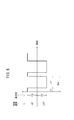
図7は、この電流進角90゜と電流進角270゜を連続的に切り替えている状態でのモータ20で発生する発熱量の変化のイメージを示している。
FIG. 7 shows an image of a change in the amount of heat generated in the
モータ20のステータ32に発生している合成磁束φsの変化(ステータコアを通過する合成磁束φsの向きの変化)によりステータ32に鉄損が発生し、この鉄損によりステータ32が発熱する。同時に、コイル30に通電される電流値I1a、I2aによりコイル30に銅損(ジュール熱)が発生し、この銅損によりコイル30が発熱する。
Iron loss occurs in the
また、電流進角270゜での電流値I2aの大きさを電流進角90゜での電流値I1aの大きさより大きい値に設定しているので銅損は、電流進角270゜での電流値I2aが通電している期間の方が、電流進角90゜での電流値I1aが通電している期間に比較して大きいことが分かる。合成発熱の発熱量は、図7に示すとおり、鉄損と銅損の和で表される。
Further, since the magnitude of the current value I2a at the current advance angle 270 ° is set to be larger than the magnitude of the current value I1a at the
以上説明したように、上述した実施形態の第1実施例によれば、電気自動車10の始動前に、0トルクとなる電流進角90゜での第1電流としての電流値I1aと、0トルクとなる電流進角270゜での第2電流としての電流値I2aとを交互にモータ20のコイル30に通電させるようにしているので、油100中に浸漬しているコイル30の銅損による発熱に加え、油100中に浸漬しているステータ32のコアの鉄損による発熱の相乗効果で油100を急速に暖めることが可能となり、油昇温効率が高くなり、油100を迅速に暖めることができる。通常、コイル30の耐熱温度は略200[℃]程度であるのに対し、コアの耐熱はこれ以上の温度であるため、コアを暖めた方がモータ20の保護・寿命の観点から好ましい。
As described above, according to the first example of the above-described embodiment, the current value I1a as the first current at the current advance angle of 90 ° and the zero torque before the start of the
この場合、電流進角90゜は、永久磁石26により発生する磁石磁束φmと逆方向にコイル磁束φcを発生させるので、永久磁石26により発生する磁石磁束φmと同方向にコイル磁束φcが発生する電流進角270゜(強め界磁位相)での第2電流の電流値I2aを、電流進角90゜での第1電流の電流値I1aより大きな値としているので永久磁石26の減磁を防止することができる。
In this case, since the current advance angle of 90 ° generates the coil magnetic flux φc in the direction opposite to the magnet magnetic flux φm generated by the
ここで、モータ20が始動前であるか否かを、ステップS6において、始動前であるか否かの判定器を兼用する駐車ブレーキスイッチ70及びシフト位置検出スイッチ72により駐車ブレーキが作動位置にあるか又はシフト位置がパーキング位置Pにあるかにより検出しているので、始動前であることを確実に判定でき、したがって、電気自動車10の確実な停止時に油温制御(油温昇温制御)を行うことができる。モータ20が始動前であるか否かの判定は、外部充電ユニット12(外部充電器)による充電中、又は回転磁界の非付与中等であるか否かにより判定することもできる。
Here, whether or not the
上記した電流進角90゜及び270゜の通電位相では、原理的に、0トルク(0[N・m]となりモータの回転トルクは発生しないが、ロータ28の磁極位置検出誤差等によるロータ28からみたときの位相ずれにより若干の回転トルクが発生してしまった場合においても、駐車ブレーキが作動位置にあるか又はシフト位置がパーキング位置Pにある場合には、車両の自走を回避することができる。 In the energization phase at the current advance angles of 90 ° and 270 °, in principle, the torque is 0 torque (0 [N · m] and no motor rotation torque is generated. Even if a slight rotational torque is generated due to a phase shift when viewed, if the parking brake is in the operating position or the shift position is in the parking position P, it is possible to avoid self-running of the vehicle. it can.
車両の前回使用時から間もない時点での使用などで、油温Toが所定温度Tp以上に保持されている場合には、昇温動作が行われないので、電力の消費を抑制することができる。 When the oil temperature To is maintained at a predetermined temperature Tp or higher, such as when the vehicle is used shortly after the previous use, the temperature raising operation is not performed, so that power consumption can be suppressed. it can.
また、油温To及びコイル温度Tcを監視しているので、モータ・ギアアセンブリ24の過熱を保護することができる。
Further, since the oil temperature To and the coil temperature Tc are monitored, overheating of the motor /
なお、電気自動車10の始動時点を設定可能なタイマ設定器104を設けており、タイマ設定器104により次回の始動予定時刻(始動時点)が設定されたとき、設定された始動予定時刻において、油温Toが所定温度Tpとなるように通電制御を行うようにしているので(ステップS7が肯定で通電を開始する。)、油温Toを上昇させるための電力を効率よく使用することができる。換言すれば、充電時に常に油温の昇温動作を行うのではなく、車両次回使用時の直前に昇温制御が終わるように制御されるので油温上昇制御のための電力を節約することができる。
Note that a
[第2実施例]
なお、図4に示したように、電流進角90゜では、永久磁石26により発生する磁石磁束φmと逆方向、すなわち永久磁石26を減磁する方向にコイル磁束φcが発生するので、第2実施例として、例えば、図8、図9に示すように、永久磁石26により発生する磁石磁束φmと同方向にコイル磁束φcが発生する電流進角270゜での第2電流の電流値I2bの通電期間T2を、電流進角90゜での第1電流の電流値I1b(この例では、I1b=I2b)の通電期間T1より長い通電期間T2とすることでも、永久磁石26の減磁を防止しながら、コアを鉄損により発熱させることができる。
[Second Embodiment]
As shown in FIG. 4, when the current advance angle is 90 °, the coil magnetic flux φc is generated in the direction opposite to the magnetic flux φm generated by the
上述した第1実施例及び第2実施例によれば、充電プラグ、この実施形態では、コネクタ86を外部充電ユニット12に接続して充電される電気自動車10において、外部から供給される電力によってモータ20に電流進角90゜と270゜を連続的に切り替えて通電することで、モータ20のコイル30の銅損による発熱に加え、モータ20のコアの鉄損により発熱させることができるので、相乗効果の発熱によりモータ・ギアアセンブリ24の潤滑油等として機能する油100を始動前に暖めておくことで、通常、油100が冷えている車両始動時から油100のフリクションを低減させることが可能となり、電気自動車10の走行電費を向上させることができる。
According to the first example and the second example described above, the charging plug, in this embodiment, the
この実施形態では、タイマ設定器104により次回の始動時点が設定されたとき、設定された始動時点において、油温Toが所定温度となる(かつ、バッテリ82が満充電状態となる)ように通電制御を行っているので、油温Toを上昇させるためのバッテリ82の電力(外部AC電源98が接続されている場合には、外部AC電源98の電力)を最小限の電力とすることができ、電力を効率よく使用することができる。
In this embodiment, when the next start time is set by the
なお、この発明は、上述の実施形態に限らず、この明細書の記載内容に基づき、種々の構成を採り得ることはもちろんである。 Note that the present invention is not limited to the above-described embodiment, and it is needless to say that various configurations can be adopted based on the contents described in this specification.
10…電気自動車 12…外部充電ユニット
14…電気自動車システム 18…ケーシング
20…モータ 22…ギアトレイン
24…モータ・ギアアセンブリ 26…永久磁石
28…ロータ 30…コイル
32…ステータ 34…回転軸
36…レゾルバ 60…ECU
99…油貯留室 100…油
DESCRIPTION OF
99 ... Oil storage chamber 100 ... Oil
Claims (6)
前記モータが始動前であるか否かを判定する判定ステップと、
始動前であると判定したとき、0トルクとなる電流進角90゜での第1電流と、前記0トルクとなる前記第1電流とは異なる方向に磁束を発生させる電流進角270゜での第2電流とを交互に前記モータのコイルに通電させる通電ステップと、を備え、
前記通電ステップでは、
前記電流進角270゜での第2電流の電流値を、前記電流進角90゜での第1電流の電流値より大きな値とするか、前記電流進角270゜での第2電流の通電期間を、前記電流進角90゜での第1電流の通電期間より長い期間とする
ことを特徴とする電気自動車の油温上昇制御方法。 An oil temperature rise control method for an electric vehicle that shares the lubricating oil of a gear and the cooling oil of a permanent magnet synchronous motor driven in three phases , and transmits the rotational torque of the motor to wheels through the gear,
A determination step of determining whether or not the motor is before starting;
When it is determined that the pre-start, a first current at a current advance angle 90 ° to be 0 torque, at a current advance angle 270 ° to generate a magnetic flux in a direction different from the first current serving as the 0 torque An energization step of energizing the coil of the motor alternately with a second current ,
In the energization step,
The current value of the second current at the current advance angle of 270 ° is set to be larger than the current value of the first current at the current advance angle of 90 °, or the second current is energized at the current advance angle of 270 °. period, the current advance angle 90 oil temperature rise control method of an electric vehicle, characterized in that shall be the longer period conduction period of the first current °.
前記モータが始動前であるか否かを判定するステップでは、
駐車ブレーキが作動位置又はシフト位置がパーキング位置にあることを検出したとき、始動前であると判定する
ことを特徴とする電気自動車の油温上昇制御方法。 In an oil temperature increase control method for an electric vehicle according to claim 1 Symbol placement,
In the step of determining whether or not the motor is before starting,
An oil temperature rise control method for an electric vehicle, characterized in that when the parking brake detects that the operating position or the shift position is in the parking position, it is determined that the vehicle is not started.
当該電気自動車の始動時点を設定可能なタイマをさらに設け、
前記通電ステップでは、
前記タイマにより次回の始動時点が設定されたとき、設定された始動時点において、前記油温が適正温度となるように通電制御を行う
ことを特徴とする電気自動車の油温上昇制御方法。 In the oil temperature rise control method of the electric vehicle according to claim 1 or 2 ,
A timer that can set the starting time of the electric vehicle is further provided,
In the energization step,
When the next start time is set by the timer, the energization control is performed so that the oil temperature becomes an appropriate temperature at the set start time.
前記電気自動車は、始動前に外部充電器に接続され、前記外部充電器の電力により、前記0トルクとなる前記第1及び第2電流が前記モータに供給される前記通電制御が行われる
ことを特徴とする電気自動車の油温上昇制御方法。 In the electric vehicle oil temperature rise control method according to claim 3 ,
The electric vehicle is connected to an external charger before starting, and the energization control is performed such that the first and second currents having the zero torque are supplied to the motor by the electric power of the external charger. An oil temperature rise control method for an electric vehicle, which is characterized.
前記モータが始動前であるか否かを判定する判定器と、
始動前であると判定したとき、0トルクとなる電流進角90゜での第1電流と、前記0トルクとなる前記第1電流とは異なる方向に磁束を発生させる電流進角270゜での第2電流とを交互に前記モータのコイルに通電させる通電制御器と、を備え、
前記通電制御器は、
前記電流進角270゜での第2電流の電流値を、前記電流進角90゜での第1電流の電流値より大きな値とするか、前記電流進角270゜での第2電流の通電期間を、前記電流進角90゜での第1電流の通電期間より長い期間とする
ことを特徴とする電気自動車の油温上昇制御装置。 An oil temperature rise control device for an electric vehicle that shares the lubricating oil of the gear and the cooling oil of the permanent magnet synchronous motor driven in three phases , and transmits the rotational torque of the motor to the wheels via the gear,
A determiner for determining whether or not the motor is before starting;
When it is determined that the pre-start, a first current at a current advance angle 90 ° to be 0 torque, at a current advance angle 270 ° to generate a magnetic flux in a direction different from the first current serving as the 0 torque An energization controller that alternately energizes the coil of the motor with a second current ,
The energization controller is
The current value of the second current at the current advance angle of 270 ° is set to be larger than the current value of the first current at the current advance angle of 90 °, or the second current is energized at the current advance angle of 270 °. period, the oil temperature rise control apparatus for an electric vehicle, characterized in that shall be the longer period conduction period of the first current of the current advance angle of 90 °.
Priority Applications (2)
| Application Number | Priority Date | Filing Date | Title |
|---|---|---|---|
| JP2009245516A JP4881991B2 (en) | 2009-10-26 | 2009-10-26 | Electric vehicle oil temperature rise control method and apparatus, and electric vehicle |
| US12/911,319 US8604738B2 (en) | 2009-10-26 | 2010-10-25 | Method of and apparatus for controlling oil temperature increase for electric vehicle and electric vehicle |
Applications Claiming Priority (1)
| Application Number | Priority Date | Filing Date | Title |
|---|---|---|---|
| JP2009245516A JP4881991B2 (en) | 2009-10-26 | 2009-10-26 | Electric vehicle oil temperature rise control method and apparatus, and electric vehicle |
Publications (2)
| Publication Number | Publication Date |
|---|---|
| JP2011089625A JP2011089625A (en) | 2011-05-06 |
| JP4881991B2 true JP4881991B2 (en) | 2012-02-22 |
Family
ID=43897842
Family Applications (1)
| Application Number | Title | Priority Date | Filing Date |
|---|---|---|---|
| JP2009245516A Expired - Fee Related JP4881991B2 (en) | 2009-10-26 | 2009-10-26 | Electric vehicle oil temperature rise control method and apparatus, and electric vehicle |
Country Status (2)
| Country | Link |
|---|---|
| US (1) | US8604738B2 (en) |
| JP (1) | JP4881991B2 (en) |
Families Citing this family (26)
| Publication number | Priority date | Publication date | Assignee | Title |
|---|---|---|---|---|
| JP5853708B2 (en) * | 2012-01-10 | 2016-02-09 | 日産自動車株式会社 | Charger |
| GB2503670B (en) * | 2012-07-03 | 2014-12-10 | Dyson Technology Ltd | Method of preheating a brushless motor |
| GB2503671B (en) * | 2012-07-03 | 2014-12-17 | Dyson Technology Ltd | Control of a brushless motor |
| JP5509289B2 (en) * | 2012-10-05 | 2014-06-04 | 本田技研工業株式会社 | Vehicle drive device |
| JP6192919B2 (en) | 2012-11-02 | 2017-09-06 | Ntn株式会社 | In-wheel motor drive device |
| JP6192921B2 (en) | 2012-11-08 | 2017-09-06 | Ntn株式会社 | Low-temperature drive control device for motor-equipped automobiles |
| JP5720664B2 (en) * | 2012-12-06 | 2015-05-20 | トヨタ自動車株式会社 | Electric vehicle and control method thereof |
| KR101592705B1 (en) * | 2014-06-11 | 2016-02-19 | 현대자동차주식회사 | Fuel cell system and contolling method thereof |
| US9242576B1 (en) * | 2014-07-25 | 2016-01-26 | GM Global Technology Operations LLC | Method and apparatus for controlling an electric machine |
| DE102014217959A1 (en) * | 2014-09-09 | 2016-03-10 | Bayerische Motoren Werke Aktiengesellschaft | Method and air conditioning device for air conditioning an interior of an electrically driven vehicle |
| EP3015677B1 (en) | 2014-10-28 | 2018-04-04 | Toyota Jidosha Kabushiki Kaisha | Control apparatus for internal combustion engine |
| US10493978B2 (en) * | 2016-03-18 | 2019-12-03 | Gkn Automotive Ltd. | Electric drive |
| JP2017189051A (en) * | 2016-04-07 | 2017-10-12 | 株式会社デンソー | Control apparatus of motor |
| DE102016206765B4 (en) * | 2016-04-21 | 2023-02-02 | Bayerische Motoren Werke Aktiengesellschaft | Device and method for controlling a synchronous machine arranged in a vehicle |
| DE102016207912A1 (en) | 2016-05-09 | 2017-11-09 | Audi Ag | Method for operating a motor vehicle and motor vehicle |
| EP3285392B1 (en) * | 2016-08-19 | 2022-05-11 | Melexis Technologies NV | Method and device for starting and/or driving a fan at low temperature |
| US9988955B1 (en) | 2016-11-28 | 2018-06-05 | GM Global Technology Operations LLC | Dry sump system warm up strategy |
| WO2019193749A1 (en) * | 2018-04-06 | 2019-10-10 | 三菱電機株式会社 | Ac rotating machine apparatus |
| JP6989539B2 (en) * | 2019-01-21 | 2022-01-05 | 本田技研工業株式会社 | vehicle |
| DE102019203342A1 (en) * | 2019-03-12 | 2020-09-17 | Robert Bosch Gmbh | Method for increasing the battery electric range of a vehicle |
| DE102019204369A1 (en) * | 2019-03-28 | 2020-10-01 | Zf Friedrichshafen Ag | Method for improving the low temperature behavior of an electric or hybrid vehicle |
| JP7367429B2 (en) * | 2019-09-27 | 2023-10-24 | ニデックパワートレインシステムズ株式会社 | Motor unit control device |
| CN112670620A (en) * | 2020-04-03 | 2021-04-16 | 长城汽车股份有限公司 | Vehicle and heating method and device of battery pack of vehicle |
| KR20210136237A (en) * | 2020-05-07 | 2021-11-17 | 현대자동차주식회사 | Oil tempertature rising system and method for vehicle |
| CN113939994B (en) * | 2021-06-29 | 2024-05-14 | 华为数字能源技术有限公司 | Heating control method and device, oil pump motor and heat exchange system |
| DE102021003612B4 (en) | 2021-07-13 | 2024-03-14 | Hochschule Offenburg (Körperschaft des öffentlichen Rechts) | Method for operating a battery-electric vehicle |
Family Cites Families (13)
| Publication number | Priority date | Publication date | Assignee | Title |
|---|---|---|---|---|
| JP3641871B2 (en) * | 1996-04-04 | 2005-04-27 | トヨタ自動車株式会社 | Control device for permanent magnet motor |
| JPH10164882A (en) * | 1996-11-25 | 1998-06-19 | Sanyo Denki Co Ltd | Method and apparatus for control of induction motor |
| JP2003199378A (en) * | 2001-12-25 | 2003-07-11 | Yaskawa Electric Corp | Spindle motor controller for machine tool |
| JP3918631B2 (en) * | 2002-05-20 | 2007-05-23 | トヨタ自動車株式会社 | Oil heating device |
| JP2004015892A (en) * | 2002-06-05 | 2004-01-15 | Toshiba Corp | Inverter controlling device and electric vehicle |
| JP4715675B2 (en) * | 2006-08-08 | 2011-07-06 | トヨタ自動車株式会社 | Method for raising the temperature of a permanent magnet provided on a vehicle and a rotor of a motor generator mounted on the vehicle |
| JP5082495B2 (en) * | 2007-02-21 | 2012-11-28 | トヨタ自動車株式会社 | Electric rotating machine power supply control device |
| JP2008278557A (en) * | 2007-04-25 | 2008-11-13 | Toyota Motor Corp | Controller of electric vehicle |
| US7782021B2 (en) * | 2007-07-18 | 2010-08-24 | Tesla Motors, Inc. | Battery charging based on cost and life |
| JP4485566B2 (en) | 2007-11-13 | 2010-06-23 | 本田技研工業株式会社 | Motor type power unit |
| JP5076990B2 (en) * | 2008-03-18 | 2012-11-21 | 株式会社デンソー | Battery warm-up system |
| JP2009254105A (en) * | 2008-04-04 | 2009-10-29 | Toyota Motor Corp | Rotary electric machine control system |
| JP5200991B2 (en) * | 2009-02-23 | 2013-06-05 | マツダ株式会社 | Motor control method and apparatus for electric vehicle |
-
2009
- 2009-10-26 JP JP2009245516A patent/JP4881991B2/en not_active Expired - Fee Related
-
2010
- 2010-10-25 US US12/911,319 patent/US8604738B2/en not_active Expired - Fee Related
Also Published As
| Publication number | Publication date |
|---|---|
| JP2011089625A (en) | 2011-05-06 |
| US8604738B2 (en) | 2013-12-10 |
| US20110095717A1 (en) | 2011-04-28 |
Similar Documents
| Publication | Publication Date | Title |
|---|---|---|
| JP4881991B2 (en) | Electric vehicle oil temperature rise control method and apparatus, and electric vehicle | |
| JP4876661B2 (en) | Electric generator for vehicle | |
| TW575718B (en) | Method of starting an electric brushless rotating machine for driving an internal combustion engine | |
| CN104753188A (en) | Motor, compressor and method for controlling motor or compressor | |
| CN107786144B (en) | Circuit and control method thereof | |
| JP3359321B2 (en) | Drive system and method for operating the drive system | |
| US20210111614A1 (en) | Rotary electrical machine with an optimised configuration | |
| JP2020043740A (en) | Motor generator control device | |
| JP2012186917A (en) | Motor controller and motor control method | |
| JP2016073039A (en) | Control device of electric vehicle | |
| JP2016178842A (en) | Motor oil temperature rise controller for electric vehicle | |
| KR100698218B1 (en) | Driving circuit of the hybrid induction motor | |
| JP2004187339A (en) | Controller for motor to be mounted on car and motor system for vehicle | |
| JP2005045927A (en) | Motor drive system and electric automobile | |
| JP2004320861A (en) | Controller for three-phase motor-generator for vehicle | |
| JP2007110781A (en) | Motor controller | |
| JP2016147577A (en) | Cooling device for vehicular rotating machine | |
| JP2019065791A (en) | Starting device for engine | |
| JP2023047854A (en) | Electric motor control device | |
| WO2017203479A1 (en) | Generator device of electrical energy with permanent magnets, particularly for the supply of electrical loads and/or batteries of vehicles | |
| JP2002191158A (en) | Vehicle motor-generator | |
| KR101537622B1 (en) | motor and the controlling method of the same | |
| JP2000104548A (en) | Water pump | |
| JP2016193681A (en) | Cooling device of rotary electric machine for vehicle | |
| JP2002191195A (en) | Motor-generator for vehicle |
Legal Events
| Date | Code | Title | Description |
|---|---|---|---|
| A977 | Report on retrieval |
Free format text: JAPANESE INTERMEDIATE CODE: A971007 Effective date: 20110818 |
|
| A131 | Notification of reasons for refusal |
Free format text: JAPANESE INTERMEDIATE CODE: A131 Effective date: 20110823 |
|
| A521 | Request for written amendment filed |
Free format text: JAPANESE INTERMEDIATE CODE: A523 Effective date: 20111021 |
|
| TRDD | Decision of grant or rejection written | ||
| A01 | Written decision to grant a patent or to grant a registration (utility model) |
Free format text: JAPANESE INTERMEDIATE CODE: A01 Effective date: 20111108 |
|
| A01 | Written decision to grant a patent or to grant a registration (utility model) |
Free format text: JAPANESE INTERMEDIATE CODE: A01 |
|
| A61 | First payment of annual fees (during grant procedure) |
Free format text: JAPANESE INTERMEDIATE CODE: A61 Effective date: 20111205 |
|
| R150 | Certificate of patent or registration of utility model |
Free format text: JAPANESE INTERMEDIATE CODE: R150 |
|
| FPAY | Renewal fee payment (event date is renewal date of database) |
Free format text: PAYMENT UNTIL: 20141209 Year of fee payment: 3 |
|
| LAPS | Cancellation because of no payment of annual fees |