JP4878545B2 - Bridged-LAN and communication node device - Google Patents
Bridged-LAN and communication node device Download PDFInfo
- Publication number
- JP4878545B2 JP4878545B2 JP2006330992A JP2006330992A JP4878545B2 JP 4878545 B2 JP4878545 B2 JP 4878545B2 JP 2006330992 A JP2006330992 A JP 2006330992A JP 2006330992 A JP2006330992 A JP 2006330992A JP 4878545 B2 JP4878545 B2 JP 4878545B2
- Authority
- JP
- Japan
- Prior art keywords
- lan
- cos
- mst
- vlan
- relay network
- Prior art date
- Legal status (The legal status is an assumption and is not a legal conclusion. Google has not performed a legal analysis and makes no representation as to the accuracy of the status listed.)
- Expired - Fee Related
Links
Images


Classifications
-
- H—ELECTRICITY
- H04—ELECTRIC COMMUNICATION TECHNIQUE
- H04L—TRANSMISSION OF DIGITAL INFORMATION, e.g. TELEGRAPHIC COMMUNICATION
- H04L12/00—Data switching networks
- H04L12/28—Data switching networks characterised by path configuration, e.g. LAN [Local Area Networks] or WAN [Wide Area Networks]
- H04L12/46—Interconnection of networks
- H04L12/4641—Virtual LANs, VLANs, e.g. virtual private networks [VPN]
-
- H—ELECTRICITY
- H04—ELECTRIC COMMUNICATION TECHNIQUE
- H04L—TRANSMISSION OF DIGITAL INFORMATION, e.g. TELEGRAPHIC COMMUNICATION
- H04L12/00—Data switching networks
- H04L12/28—Data switching networks characterised by path configuration, e.g. LAN [Local Area Networks] or WAN [Wide Area Networks]
- H04L12/46—Interconnection of networks
- H04L12/4604—LAN interconnection over a backbone network, e.g. Internet, Frame Relay
- H04L12/462—LAN interconnection over a bridge based backbone
-
- H—ELECTRICITY
- H04—ELECTRIC COMMUNICATION TECHNIQUE
- H04L—TRANSMISSION OF DIGITAL INFORMATION, e.g. TELEGRAPHIC COMMUNICATION
- H04L45/00—Routing or path finding of packets in data switching networks
-
- H—ELECTRICITY
- H04—ELECTRIC COMMUNICATION TECHNIQUE
- H04L—TRANSMISSION OF DIGITAL INFORMATION, e.g. TELEGRAPHIC COMMUNICATION
- H04L45/00—Routing or path finding of packets in data switching networks
- H04L45/02—Topology update or discovery
- H04L45/04—Interdomain routing, e.g. hierarchical routing
-
- H—ELECTRICITY
- H04—ELECTRIC COMMUNICATION TECHNIQUE
- H04L—TRANSMISSION OF DIGITAL INFORMATION, e.g. TELEGRAPHIC COMMUNICATION
- H04L45/00—Routing or path finding of packets in data switching networks
- H04L45/302—Route determination based on requested QoS
-
- H—ELECTRICITY
- H04—ELECTRIC COMMUNICATION TECHNIQUE
- H04L—TRANSMISSION OF DIGITAL INFORMATION, e.g. TELEGRAPHIC COMMUNICATION
- H04L45/00—Routing or path finding of packets in data switching networks
- H04L45/48—Routing tree calculation
-
- H—ELECTRICITY
- H04—ELECTRIC COMMUNICATION TECHNIQUE
- H04L—TRANSMISSION OF DIGITAL INFORMATION, e.g. TELEGRAPHIC COMMUNICATION
- H04L45/00—Routing or path finding of packets in data switching networks
- H04L45/76—Routing in software-defined topologies, e.g. routing between virtual machines
-
- H—ELECTRICITY
- H04—ELECTRIC COMMUNICATION TECHNIQUE
- H04L—TRANSMISSION OF DIGITAL INFORMATION, e.g. TELEGRAPHIC COMMUNICATION
- H04L69/00—Network arrangements, protocols or services independent of the application payload and not provided for in the other groups of this subclass
- H04L69/30—Definitions, standards or architectural aspects of layered protocol stacks
- H04L69/32—Architecture of open systems interconnection [OSI] 7-layer type protocol stacks, e.g. the interfaces between the data link level and the physical level
- H04L69/322—Intralayer communication protocols among peer entities or protocol data unit [PDU] definitions
- H04L69/326—Intralayer communication protocols among peer entities or protocol data unit [PDU] definitions in the transport layer [OSI layer 4]
Landscapes
- Engineering & Computer Science (AREA)
- Computer Networks & Wireless Communication (AREA)
- Signal Processing (AREA)
- Computer Security & Cryptography (AREA)
- Data Exchanges In Wide-Area Networks (AREA)
- Small-Scale Networks (AREA)
Description
本発明は、Bridged-LANに関し、更に詳しくは、VLANにスパニングツリーを適用したBridged-LANと、それに適用される通信ノード装置、端末装置およびゲートウェイ装置に関する。 The present invention relates to a bridged-LAN, and more particularly to a bridged-LAN in which a spanning tree is applied to a VLAN, and a communication node device, a terminal device, and a gateway device applied to the bridged-LAN.
近年、地理的に分散した企業内の複数のLAN(Local Area Network)を中継網、例えば、公衆網を介して接続したネットワーク形態が増加している。図18は、このようなネットワーク形態の1例を示す。ここでは、A社のLAN:#A1と#A2とが、中継網NWを介して接続されている。同様に、B社のLAN:#B1と#B2も、中継網NWを介して接続されている。例えば、A社のLAN:#A1に収容された端末装置(パーソナルコンピュータ)PC−A1は、中継網NWを通して、A社のLAN#A2に所属する端末装置(パーソナルコンピュータ)PC−A2とデータを送受信する。 In recent years, a network form in which a plurality of LANs (Local Area Networks) in geographically dispersed enterprises are connected via a relay network, for example, a public network, is increasing. FIG. 18 shows an example of such a network configuration. Here, LANs of company A: # A1 and # A2 are connected via a relay network NW. Similarly, the LANs of company B: # B1 and # B2 are also connected via the relay network NW. For example, a terminal device (personal computer) PC-A1 accommodated in LAN A of company A: # A1 receives data from a terminal device (personal computer) PC-A2 belonging to LAN # A2 of company A through the relay network NW. Send and receive.
中継網NWは、耐障害性を向上するために、一般的に、複数台のブリッジBR(図18ではBR1〜BR4)で、冗長化された複数のパスを形成したネットワーク構成となっている。このように、複数のLANがブリッジを介して接続された形態のネットワークを「Bridged−LAN」と呼ぶ。中継網NWにおいて、複数のブリッジがループ状に接続されると、例えば、ARP(Address Resolution Protocol)フレームのように、宛先アドレスとしてブロードキャスト・アドレスを持つフレームが、ブリッジからブリッジに転送され続け、所謂、ブロードキャスト・ストームが発生することがある。ブロードキャスト・ストームを回避するための技術として、IEEE802.1d(非特許文献1)で規定されたSTP(Spanning Tree Protocol)がある。 In order to improve fault tolerance, the relay network NW generally has a network configuration in which a plurality of redundant paths are formed by a plurality of bridges BR (BR1 to BR4 in FIG. 18). In this way, a network in which a plurality of LANs are connected via a bridge is referred to as “Bridged-LAN”. When a plurality of bridges are connected in a loop in the relay network NW, for example, a frame having a broadcast address as a destination address, such as an ARP (Address Resolution Protocol) frame, continues to be transferred from the bridge to the bridge. Broadcast storms may occur. As a technique for avoiding broadcast storm, there is STP (Spanning Tree Protocol) defined in IEEE 802.1d (Non-patent Document 1).
STPでは、このようなループ状のネットワークを論理的にツリー構造のネットワーク(スパニングツリー)として管理することによって、ブロードキャスト・ストームを回避している。具体的に言うと、STPでは、ブリッジIDの値によって、ループを形成している複数のブリッジのうちの1つをRootブリッジとして選択する。残りのブリッジでは、回線速度に基づいて算出されたコスト値が最小になるように、Rootブリッジ迄の経路を決定し、コスト値が最小でない経路を閉塞(ブロッキング)することによって、物理的にはループ状に接続されたネットワークを論理的なスパニングツリー・ネットワークとして管理する。 In STP, such a loop network is logically managed as a network having a tree structure (spanning tree), thereby avoiding a broadcast storm. More specifically, in the STP, one of a plurality of bridges forming a loop is selected as a root bridge according to the bridge ID value. In the remaining bridges, the route to the Root bridge is determined so that the cost value calculated based on the line speed is minimized, and the route whose cost value is not the minimum is blocked (blocked) physically. A network connected in a loop is managed as a logical spanning tree network.
各ブリッジは、Rootブリッジ方向に最小コストをもつ複数の経路(隣接ブリッジ)が存在していた場合、ブリッジIDの小さい隣接ブリッジを経由する経路を優先させる。STPでは、上述した経路決定過程において、ブリッジIDと、回線速度によって決まるコスト値とを搬送する「BPDU」と呼ばれるデータをブリッジ間でやりとりする。 When there are a plurality of paths (adjacent bridges) having a minimum cost in the root bridge direction, each bridge gives priority to a path that passes through an adjacent bridge with a small bridge ID. In the STP, data called “BPDU” that carries a bridge ID and a cost value determined by the line speed is exchanged between the bridges in the above-described route determination process.
図19は、STPを適用したBridged−LANのネットワーク構成の1例を示す。
図19では、4つのLAN:#1〜#4が、ループ状に接続されたブリッジBR1〜BR4を介して、相互接続されている。各LANは、複数のPCを収容できるが、ここでは簡略化して、各LANにPCが1台ずつ接続されている。
FIG. 19 shows an example of a bridged-LAN network configuration to which STP is applied.
In FIG. 19, four LANs: # 1 to # 4 are interconnected via bridges BR1 to BR4 connected in a loop. Each LAN can accommodate a plurality of PCs, but here, for simplicity, one PC is connected to each LAN.
ブリッジBR1〜BR4のうち、最小IDをもつBR1がRootブリッジとなる。RootブリッジBR1では、3つのEthernetポートP11、P12、P13のうち、ポートP11とP12を指定ポート(Designated Port)DPとしている。ブリッジBR2では、RootブリッジBR1に近いEthernetポートP21をルートポート(Root Port)RP、Rootブリッジから遠いEthernetポートP22を指定ポートDPとしている。 Of the bridges BR1 to BR4, BR1 having the minimum ID is a Root bridge. In the root bridge BR1, among the three Ethernet ports P11, P12, and P13, the ports P11 and P12 are designated ports (Designated Ports) DP. In the bridge BR2, the Ethernet port P21 close to the Root bridge BR1 is a root port (Root Port) RP, and the Ethernet port P22 far from the Root bridge is a designated port DP.
また、ブリッジBR4では、Rootブリッジに近いEthernetポートP41をルートポートRP、Rootブリッジから遠いEthernetポートP42を指定ポートDPとし、ブリッジBR3では、ブリッジBR2と接続されるEthernetポートP32をルートポートRP、ブリッジBR4と接続されるEthernetポートP31を非指定ポート(Non Designated Port)NDPとしている。これによって、ブリッジBR3とBR4との間の回線がブロッキングされている。このように、STPでは、Rootブリッジと、RP、DP、NDPを決定することによって、Rootブリッジを頂点とするスパニングツリーを構成できる。 In the bridge BR4, the Ethernet port P41 near the Root bridge is set as the root port RP, and the Ethernet port P42 far from the Root bridge is set as the designated port DP. In the bridge BR3, the Ethernet port P32 connected to the bridge BR2 is set as the root port RP and the bridge. The Ethernet port P31 connected to the BR4 is a non-designated port NDP. As a result, the line between the bridges BR3 and BR4 is blocked. Thus, in STP, a spanning tree having the Root bridge as a vertex can be configured by determining the Root bridge and RP, DP, and NDP.
近年では、ネットワークの大規模化に伴って、1つのLANを仮想的な複数のLANに分割したVLAN(Virtual Local Area Network)も運用されている。VLANについては、IEEE802.1q(非特許文献2)で規定されている。ネットワークを複数のVLANに分割すると、ARPなどのブロードキャストフレームの到達範囲(ブロードキャストドメイン)を縮小し、ネットワーク帯域の圧迫を回避することが可能となる。 In recent years, with an increase in the scale of a network, a VLAN (Virtual Local Area Network) in which one LAN is divided into a plurality of virtual LANs is also operated. The VLAN is defined in IEEE 802.1q (Non-Patent Document 2). When the network is divided into a plurality of VLANs, it is possible to reduce the reach range (broadcast domain) of a broadcast frame such as ARP and avoid the compression of the network bandwidth.
上述したVLAN上でSTPを実現する技術として、IEEE802.1(非特許文献3)で規定されたMST(Multiple Spanning Tree Protocol)がある。MSTでは、1つ或いは複数のVLANからなるMST instance毎にスパニングツリーが構成される。 As a technique for realizing STP on the VLAN described above, there is MST (Multiple Spanning Tree Protocol) defined by IEEE 802.1 (Non-patent Document 3). In MST, a spanning tree is configured for each MST instance including one or a plurality of VLANs.
図20は、MSTを適用したBridged−LANのネットワーク構成の1例を示す。
ここでは、LAN#1〜#4が、ループ状に接続されたブリッジBR1〜BR4を含む中継網NW介して、相互接続されている。LAN#1には、PC1−1〜PC1−3が収容され、LAN#2〜LAN#4には、それぞれPC2、PC3、PC4が接続されている。
FIG. 20 shows an example of a bridged-LAN network configuration to which MST is applied.
Here,
図20では、Bridged−LANに、実線で示したVLAN#1と、破線で示したVLAN#2の2つのVLANが形成されている。VLAN#1には、LAN#1に接続されたPC1−1と、LAN#3の全体とが所属し、VLAN#2には、LAN#1に接続されたPC1−2、PC1−3と、LAN#2、LAN#4の全体が所属している。
In FIG. 20, two VLANs,
ここでは、VLAN#1とVLAN#2とが、互いに異なったMST instanceに所属するものとし、それぞれのMST instanceを「MST instance #1」、「MST instance #2」と定義する。MSTでは、MST instance毎にRootブリッジRBを選択し、ブリッジ毎にRP、DP、NDPを決定している。以下の説明では、MST instance#1ではBR1が、MST instance #2ではBR3が、それぞれRootブリッジRBとして選択されたものと仮定する。
Here, it is assumed that
ブリッジBR1では、EthernetポートP11が、MST instance #1、#2の双方で指定ポートDPとなり、EthernetポートP12が、MST instance #1ではDP、MST instance #2ではNDPとなっている。また、ブリッジBR2では、EthernetポートP21が、MST instance #1でRP、MST instance #2でDPとなり、EthernetポートP22が、MST instance #1、#2の双方でDPとなっている。
In the bridge BR1, the Ethernet port P11 is the designated port DP in both
ブリッジBR3では、EthernetポートP31が、MST instance #1でNDP、MST instance #2でDPとなり、EthernetポートP32が、MST instance #1、#2の双方でRPとなっている。ブリッジBR4では、EthernetポートP41が、MST instance #1、#2の双方でRP、EthernetポートP42が、MST instance #1でDP、MST instance #2でRPとなっている。従って、MST instance #2では、ブリッジBR1とBR2との間、MST instance #1ではブリッジBR3とBR4との間が、それぞれブロッキングされている。
In the bridge BR3, the Ethernet port P31 is NDP in
このように、MSTによれば、複数のVLAN(図20ではVLAN#1とVLAN#2)に個別のスパニングツリーを構成でき、VLANの長所であるブロードキャストドメインの縮小と、STPの長所であるブロードキャスト・ストームの回避を同時に実現することが可能となる。
In this way, according to MST, individual spanning trees can be configured for a plurality of VLANs (
図20に示したBridged−LANにおいて、PC1−2がWEBサーバ、PC1−3がセッション管理用のSIP(Session Initiation Protocol)サーバとして機能し、PC2をWEBとSIPのクライアント、PC4をSIPのクライアントと仮定する。これらのPCは、何れもVLAN#2に所属している。WEBクライアントは、WEBサーバ(PC1−2)から、httpプロトコルに従ったWEBサービスを受けることができる。一方、SIPクライアント間では、SIPサーバ(PC1−3)を介してVoIP(Voice over IP)通信を行うことができる。
In the bridged-LAN shown in FIG. 20, PC1-2 functions as a WEB server, PC1-3 functions as a session management SIP (Session Initiation Protocol) server, PC2 functions as a WEB and SIP client, and PC4 functions as a SIP client. Assume. These PCs all belong to
VLAN#2では、ブリッジBR1のポートP12とブリッジBR2のポートP21との間がブロッキングされているため、PC2が、WEBサーバ(PC1−2)からWEBサービスを受ける場合、PC2は、ブリッジBR2、BR3、BR4、BR1を経由して、WEBサーバと通信することになる。また、SIPサーバ(PC1−3)を介してPC4とVoIP通信する場合も、PC2は、ブリッジBR2、BR3、BR4、BR1の順で経由した通信経路で、SIPサーバ(PC1−3)に接続される。
In
WEBサービスのように、厳密なリアルタイム伝送を必要としない通信サービスでは、通信フレームが経由するブリッジの個数は特に問題にはならないが、VoIPのような音声通信では、ネットワーク上でのデータ転送遅延が問題となるため、経由するブリッジの個数が少ない最小遅延経路で通信することが望まれる。 In a communication service that does not require strict real-time transmission, such as a WEB service, the number of bridges through which a communication frame passes is not particularly a problem, but in voice communication such as VoIP, there is a data transfer delay on the network. Since this is a problem, it is desirable to perform communication using a minimum delay path with a small number of bridges.
しかしながら、MSTでは、上述したようにVLAN毎にSTPが適用されており、中継網内にサービス毎に異なったスパニングツリーを構成することはできない。従って、図20において、例えば、VLAN#2に所属したPC2が、PC4とVoIP通信する場合に、BR2とBR1のみを経由する最短ルートで、SIPサーバ(PC1−3)をアクセスすることはできない。すなわち、既存のMSTでは、WEBサービスとVoIPのように、サービス種類によって異なったスパニングツリーを構成することができないという問題がある。
However, in MST, as described above, STP is applied to each VLAN, and a spanning tree different for each service cannot be configured in the relay network. Therefore, in FIG. 20, for example, when the
本発明の目的は、中継網内にサービス毎に異なったスパニングツリーを構成できるBridged-LANを提供することにある。
本発明の他の目的は、Bridged-LANの中継網内でサービス毎に異なったスパニングツリーを構成できる通信ノード装置を提供することにある。
本発明の更に他の目的は、Bridged-LANの中継網でサービス種別に適合した経路で転送可能な通信フレームを生成する通信端末装置およびゲートウェイ装置を提供することにある。
An object of the present invention is to provide a bridged-LAN in which a different spanning tree can be configured for each service in a relay network.
Another object of the present invention is to provide a communication node device capable of configuring a different spanning tree for each service in a bridged-LAN relay network.
Still another object of the present invention is to provide a communication terminal device and a gateway device that generate a communication frame that can be transferred through a route suitable for a service type in a bridged-LAN relay network.
上記目的を達成するため、本発明は、Bridged-LANの複数のLANを相互接続する中継網内に、VLAN−IDとサービスクラスとの組み合せで定義されたMST instance毎に、スパニングツリーを形成することを特徴とする。サービスクラスとしては、イーサネット(Ethernet:登録商標)フレームのヘッダ部に含まれるタグフィールドに定義されたCOS(Class Of Service)を使用できる。 To achieve the above object, the present invention forms a spanning tree for each MST instance defined by a combination of a VLAN-ID and a service class in a relay network that interconnects a plurality of bridged LANs. It is characterized by that. As the service class, COS (Class Of Service) defined in a tag field included in the header part of an Ethernet (registered trademark) frame can be used.
本発明において、Bridged-LANに接続される各端末装置(パーソナルコンピュータ)は、例えば、TCP/UDPポート番号とCOS値との対応関係を示す変換テーブルを参照して、ネットワークアプリケーションが利用するTCP/UDPポート番号と対応するCOS値を特定し、該COS値を所属VLANの識別子と共に送信フレームのヘッダ部に設定する。また、中継網を構成する各ブリッジは、VLAN−IDとCOS値との組み合わせとMST instance識別子との対応関係を示す変換テーブルを参照して、受信フレームのMST instance識別子を特定する。 In the present invention, each terminal device (personal computer) connected to the bridged-LAN refers to, for example, a TCP / UDP used by a network application with reference to a conversion table indicating a correspondence relationship between a TCP / UDP port number and a COS value. The COS value corresponding to the UDP port number is specified, and the COS value is set in the header part of the transmission frame together with the identifier of the belonging VLAN. In addition, each bridge configuring the relay network identifies the MST instance identifier of the received frame with reference to a conversion table indicating a correspondence relationship between the combination of the VLAN-ID and the COS value and the MST instance identifier.
更に詳述すると、本発明のBridged-LANは、複数のVLAN(Virtual LAN)が形成される中継網と、該中継網に接続された複数のLANとからなり、上記中継網内では、1つあるいは複数のVLANからなるMST(Multiple Spanning Tree Protocol)インスタンス毎に、論理的なスパニングツリーが形成され、上記中継網が、イーサネットフレームを送受信する複数のブリッジからなり、
各ブリッジが、VLAN識別子とサービスクラス(COS:Class of service)の値との組み合わせに対応してMSTインスタンスの識別子を定義した変換テーブルと、上記中継網内で、上記管理テーブルで定義されたMSTインスタンス識別子毎にスパニングツリーを形成するための手段とを有し、
上記各ブリッジが、受信フレームのヘッダからVLAN識別子とCOS値とを抽出し、上記変換テーブルによって、上記受信フレームのMSTインスタンス識別子を特定し、該MSTインスタンス識別子をもつスパニングツリーの経路に従って、上記受信フレームを転送することを特徴とする。
More specifically, the bridged-LAN of the present invention comprises a relay network in which a plurality of VLANs (Virtual LANs) are formed and a plurality of LANs connected to the relay network. Alternatively, a logical spanning tree is formed for each MST (Multiple Spanning Tree Protocol) instance including a plurality of VLANs, and the relay network includes a plurality of bridges that transmit and receive Ethernet frames.
Each bridge defines an MST instance identifier corresponding to a combination of a VLAN identifier and a class of service (COS) value, and an MST defined in the management table in the relay network. A means for forming a spanning tree for each instance identifier;
Each bridge extracts a VLAN identifier and a COS value from the header of the received frame, specifies the MST instance identifier of the received frame by the conversion table, and performs the reception according to the spanning tree path having the MST instance identifier. It is characterized by transferring a frame.
本発明は、MSTに従ってスパニングツリーが形成されるBridged-LANに適した通信ノード装置、端末装置およびゲートウェイを提供する。
本発明による通信ノード装置は、それぞれイーサネットフレームを送受信する複数のポートインタフェースと、VLAN識別子とサービスクラス(COS:Class of service)の値との組み合わせに対応してMSTインスタンス識別子を定義した変換テーブルと、上記中継網に、上記管理テーブルで定義されたMSTインスタンス識別子毎にスパニングツリーを形成するための手段と、上記各ポートインタフェースからイーサネットフレームを受信した時、上記変換テーブルによって、受信フレームのヘッダが示すVLAN識別子とCOSの値との組み合せに対応するMSTインスタンス識別子を特定し、該MSTインスタンス識別子をもつスパニングツリーの経路に従って、上記受信フレームを転送する経路制御部とを備えたことを特徴とする。
The present invention provides a communication node device, a terminal device, and a gateway suitable for a bridged-LAN in which a spanning tree is formed according to MST.
A communication node device according to the present invention includes a plurality of port interfaces that transmit and receive Ethernet frames, a conversion table that defines MST instance identifiers corresponding to combinations of VLAN identifiers and class of service (COS) values, and When receiving an Ethernet frame from each port interface and means for forming a spanning tree for each MST instance identifier defined in the management table in the relay network, a header of the received frame is received by the conversion table. A path control unit that identifies an MST instance identifier corresponding to a combination of a VLAN identifier and a COS value, and forwards the received frame according to a spanning tree path having the MST instance identifier. .
本発明による端末装置は、TCP/UDPポート番号とサービスクラス(COS:Class of service)の値との対応関係を示す変換テーブルと、ネットワークアプリケーションが使用するTCP/UDPポート番号に応じて、上記変換テーブルから、送信フレームに適用すべきCOS値を特定するための手段とを有し、該端末装置が所属するVLANの識別子と上記特定のCOS値とをヘッダ部に含むイーサネットフレームを上記Bridged-LANに送信することを特徴とする。 The terminal device according to the present invention converts the conversion according to the conversion table indicating the correspondence between the TCP / UDP port number and the value of class of service (COS), and the TCP / UDP port number used by the network application. Means for specifying a COS value to be applied to the transmission frame from the table, and an Ethernet frame including the identifier of the VLAN to which the terminal device belongs and the specific COS value in the header portion is the Bridged-LAN It is characterized by transmitting to.
イーサネットフレームへのCOS値の付与は、各端末装置に代わって、LANと中継網との間に位置したゲートウェイ装置で行ってもよい。本発明のゲートウェイ装置は、それぞれがポート番号によって識別される複数のポートインタフェースと、TCP/UDPポート番号とサービスクラス(COS:Class of service)の値との対応関係を示す変換テーブルと、ポート番号と対応してCOS値設定の要否を示すフラグ情報を記憶したCOS値設定テーブルと、上記各ポートインタフェースからイーサネットフレームを受信した時、上記COS値設定テーブルから、受信フレームの転送先となるポート番号と対応するフラグ情報を検索し、該フラグ情報がCOS値設定要を示す場合、上記変換テーブルから、上記受信フレームのTCP/UDPポート番号と対応するCOS値を検索し、該COS値を上記受信フレームのヘッダ部に設定して、受信フレームを上記転送先ポート番号で特定されるポートインタフェースに転送する経路制御手段とを備えたことを特徴とする。 The COS value may be assigned to the Ethernet frame by a gateway device located between the LAN and the relay network instead of each terminal device. The gateway device of the present invention includes a plurality of port interfaces each identified by a port number, a conversion table indicating a correspondence relationship between a TCP / UDP port number and a service class (COS) value, and a port number. And a COS value setting table that stores flag information indicating whether or not COS value setting is necessary, and when an Ethernet frame is received from each port interface, a port that is a transfer destination of the received frame from the COS value setting table. When the flag information corresponding to the number indicates that the COS value needs to be set, the COS value corresponding to the TCP / UDP port number of the received frame is searched from the conversion table, and the COS value is Set in the header part of the received frame and identify the received frame with the transfer destination port number And a path control means for transferring to the port interface.
本発明によれば、リアルタイム性を必要とする通信サービスに特定のCOS値を割り当てておき、特定COS値と対応づけられたスパニングツリーで予め最適な経路を確保しておくことによって、中継網内での転送遅延が少ない通信サービスを提供できる。 According to the present invention, a specific COS value is assigned to a communication service that requires real-time property, and an optimum route is secured in advance by a spanning tree associated with the specific COS value. Can provide communication services with low transfer delay.
尚、ネットワークアプリケーションの全てが、TCP/UDPを利用した通信サービスを実行するとは限らない。また、TCP/UDPを利用する通信サービスであっても、リアルタイム性に寛容な通信サービスのデータフレームは、最適経路を通す必要はない。従って、特に最適経路を必要としない通信サービスには、デフォルトのCOS値、例えば「0」を割り当てておき、デフォルトCOS値をもつ1つ、または複数のVLANをデフォルトのMST instance識別子と対応付けておくことによって、汎用的なスパニングツリーでデータフレームを転送してもよい。 Note that not all network applications execute a communication service using TCP / UDP. Even in a communication service using TCP / UDP, a data frame of a communication service that is tolerant of real-time properties does not need to pass through an optimum route. Therefore, a default COS value, for example, “0” is assigned to a communication service that does not require an optimum route, and one or more VLANs having the default COS value are associated with the default MST instance identifier. The data frame may be transferred by a general spanning tree.
本発明によれば、Bridged-LANの中継網内に、ネットワークアプリケーションが使用するサービスの種別に応じたスパニングツリーを形成できるため、同一のVLAN識別子をもつデータフレームであっても、リアルタイム性の高いデータフレームは、他のデータフレームとは異なる最適化された通信経路で転送することが可能となる。また、VLANの特徴であるブロードキャストドメインの分割効果と、STPの特長であるブロードキャストストームの抑制効果を生かすことができる。 According to the present invention, since a spanning tree corresponding to the type of service used by a network application can be formed in a bridged-LAN relay network, even a data frame having the same VLAN identifier has high real-time characteristics. The data frame can be transferred through an optimized communication path different from other data frames. In addition, it is possible to take advantage of the effect of dividing the broadcast domain, which is a feature of VLAN, and the effect of suppressing the broadcast storm, which is a feature of STP.
以下、本発明の実施例について、図面を参照して詳述する。 Hereinafter, embodiments of the present invention will be described in detail with reference to the drawings.
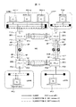
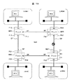
図1は、本発明が適用されるBridged−VLANのネットワーク構成例を示す。ここに例示したネットワークは、LAN#1〜LAN#4と、ループ状に接続されたブリッジBR1〜BR4を含む中継網NWとからなり、LAN#1〜LAN#4には、図20と同様、それぞれPC1−1〜PC1−3、PC2、PC3、PC4が接続されている。
FIG. 1 shows an example of a bridged-VLAN network configuration to which the present invention is applied. The network illustrated here is composed of
図1に示したBridged−LANには、実線で示したVLAN#1と、破線で示したVLAN#2の2つのVLANが形成され、図20と同様、VLAN#1には、LAN#1に接続されたPC1−1と、LAN#3全体が所属し、VLAN#2には、LAN#1に接続されたPC1−2、PC1−3と、LAN#2、LAN#4の全体が所属している。VLAN#2において、PC1−2はWEBサーバ、PC1−3はSIPサーバとして機能し、PC2は、WEBとSIPのクライアント、PC4は、SIPクライアントとなっている。
In the bridged-LAN shown in FIG. 1, two VLANs,
本実施例では、Ethernetヘッダのタグフィールドに含まれるサービスクラスCOS(Class of service)の値として、SIPサービス(TCPポート番号=「5060」)には特定値「3」を割り当て、WEBサービス(TCPポート番号=「80」)には、デフォルト値「0」を割り当てる。VLAN#1は、MST instance #1に所属する。一方、VLAN#2は、2つのスパニングツリーに分割し、COS=0のVLAN#2はMST instance#2に、COS=3のVLAN#2はMST instance#3に所属させる。
In this embodiment, a specific value “3” is assigned to the SIP service (TCP port number = “5060”) as the value of the service class COS (Class of service) included in the tag field of the Ethernet header, and the WEB service (TCP Port number = “80”) is assigned a default value “0”.
本実施例でも、MST instance毎に適当なブリッジをRootブリッジRBとし、ブリッジ毎にRP、DP、NDPを決定する。MST instance #1、MST instance #3では、BR1をRootブリッジRBとし、MST instance #2では、BR3をRootブリッジRBとする。これらのRootブリッジRBは、ネットワーク管理者によって指定される。RP、DP、NDPは、MSTによって自動的に決定される。
Also in the present embodiment, an appropriate bridge is set as a Root bridge RB for each MST instance, and RP, DP, and NDP are determined for each bridge. In
ブリッジBR1では、EthernetポートP11が、MST instance #1〜#3の全てにおいてDPとなり、EthernetポートP12が、MST instance#1、#3ではDP、MST instance#2ではNDPとなっている。ブリッジBR2では、EthernetポートP21が、MST instance#1と#3ではRP、MST instance#2ではDPとなり、EthernetポートP22が、MST instance#1〜#3の全てにおいてDPとなっている。
In the bridge BR1, the Ethernet port P11 is DP in all of
ブリッジBR3では、EthernetポートP31が、MST instance#1と#3ではNDP、MST instance#2ではDPとなっており、EthernetポートP32が、MST instance#1〜#3の全てにおいてRPとなっている。また、ブリッジBR4では、EthernetポートP41が、MST instance#1〜#3全てにおいてRPとなり、EthernetポートP42が、MST instance#1と#3ではDP、MST instance#2ではRPとなっている。
In the bridge BR3, the Ethernet port P31 is NDP in
従って、MST instance#1と#3では、BR3とBR4との間をブロッキングし、MST instance#2では、BR1とBR2との間をブロッキングして、それぞれ個別のスパニングツリーが形成される。
Therefore,
ここで、LAN#2に接続されたPC2が、WEBサーバ(PC1−2)からWEBサービスを享受する場合、PC2とWEBサーバ(PC1−2)との間では、COS=0の通信フレームが送受信される。COS=0のVLAN#2が所属するMST instance #2では、ブリッジBR1(EthernetポートP12)とブリッジBR2(EthernetポートP21)との間の回線がブロッキングされているため、PC2から送信されたフレームは、ブリッジBR2、BR3、BR4、BR1の順で通過する経路に沿って、WEBサーバ(PC1−2)に転送される。WEBサーバ(PC1−2)からPC2宛に送信されたフレームは、これとは逆順の経路で、PC2に転送される。
Here, when the
一方、PC2が、SIPサーバ(PC1−3)を介して、PC4とVoIP通信を行う場合、通信フレームのCOSの値は「3」となっている。COS=3のVLAN#2が所属するMST instance #3では、PC2とSIPサーバ(PC1−3)は、ブリッジBR2とBR1のみを経由する最短経路で交信できるため、データ転送遅延を最小にすることが可能となる。
On the other hand, when the
図2は、本発明のBridged−VLANに適用されるPCの1実施例を示す。
PCは、プロセッサ(CPU)21と、主メモリ22と、不揮発性メモリ23と、Ethernetポートインタフェース24と、これらの要素を相互接続する内部バス25とからなっている。不揮発性メモリ23には、本発明に関係するソフトウェアとして、アプリケーションソフトウェア100Mと、TCP/IPプロトコルスタック110Mと、COS値取得プログラム120Mと、TCP/UDPポート番号−COS変換テーブル130Mとが格納されている。PCの起動時には、これらのソフトウェアが、主メモリ22にロードされ(100〜130)、プロセッサ21によって実行、あるいは参照される。
FIG. 2 shows an embodiment of a PC applied to the bridged-VLAN of the present invention.
The PC includes a processor (CPU) 21, a
アプリケーションソフトウェア100(100M)としては、PCの機能に応じた適切なソフトウェアが用意される。例えば、PC4には、SIPクライアント・ソフトウェアが、PC2には、WEBクライアント・ソフトウェアとSIPクライアント・ソフトウェアが用意される。また、PC1−2には、WEBサーバ・ソフトウェア、PC1−3には、SIPサーバ・ソフトウェアが用意される。
As the application software 100 (100M), appropriate software corresponding to the function of the PC is prepared. For example, the
プロセッサ21は、アプリケーションソフトウェア100を実行し、TCP/IPプロトコルスタック110を利用して、ネットワークNWに接続された他のPCと通信する。
The
COS値取得プログラム120は、TCP/IPプロトコルスタック110によって呼び出される。COS値取得プログラム120は、TCP/UDPポート番号−COS変換テーブル130から、TCP/IPプロトコルスタック110が指定したTCP/UDPポート番号と対応するCOS値を検索し、これをTCP/IPプロトコルスタックに返答する。プロセッサ21は、送信フレームのEthernetヘッダに含まれるタグフィールドに上記COS値を設定し、Ethernetポートインタフェース24からLANに送信する。
The COS
図3は、本発明のBridged−VLANに適用されるブリッジBRの1実施例を示す。
ブリッジBRは、プロセッサ(CPU)31と、主メモリ32と、不揮発性メモリ33と、複数のEthernetポートインタフェース(INF)34−1〜34−Nと、これらの要素を相互接続する内部バス35とからなる。
FIG. 3 shows an embodiment of a bridge BR applied to the bridged-VLAN of the present invention.
The bridge BR includes a processor (CPU) 31, a
不揮発性メモリ33には、本発明に関係するソフトウェアとして、L2経路制御プログラム300Mと、MST instance取得プログラム310Mと、VLAN-ID・COS−MST instance変換テーブル350と、STP/MSTプロトコルのプログラム370Mが用意されている。ブリッジ起動時には、これらのソフトウェアが主メモリ32にロードされ(300〜370)、プロセッサ31によって実行、あるいは参照される。
The
Ethernetポートインタフェース34(34−1〜34−N)で受信された通信フレームは、L2経路制御プログラム300に従って処理される。L2経路制御プログラム300は、MST instance取得プログラム310を呼び出して、受信フレームのタグフィールドが示すCOS値と対応するMST instance識別子を特定し、このMST instance識別子で定義されたスパニングツリーの経路に従って、受信フレームを転送すべきEthernetポートインタフェースを決定する。
The communication frame received by the Ethernet port interface 34 (34-1 to 34-N) is processed according to the L2 path control
STPの経路は、STP/MSTプロトコルのプログラム370によって形成され、各ブリッジでは、MST instanceの識別子が特定されれば、スパニングツリーの構成情報から、受信フレームの転送先Ethernetポートインタフェースの識別子が判明するようになっている。
The STP path is formed by the
MST instance取得プログラム310は、VLAN-ID・COS−MST instance変換テーブル350から、L2経路制御プログラム300が指定したVLAN-IDおよびCOSと対応するMST instanceの識別子を検索し、これをL2経路制御プログラムに返す。
The MST
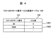
図4は、PCが備えるTCP/UDPポート番号−COS変換テーブル130の1例を示す。
TCP/UDPポート番号−COS変換テーブル130は、TCP/UDPポート番号131とCOS値132との対応関係を示す複数のテーブルエントリからなる。ここで、テーブルエントリ1301は、WEBサービス(TCPポート番号=80)のCOS値、テーブルエントリ1302は、SIPサービス(TCPポート番号=5060)のCOS値を定義している。
FIG. 4 shows an example of the TCP / UDP port number-COS conversion table 130 provided in the PC.
The TCP / UDP port number-COS conversion table 130 includes a plurality of table entries indicating the correspondence relationship between the TCP /
図5は、ブリッジBRが備えるVLAN ID・COS−MST instance変換テーブル350の1例を示す。
VLAN ID・COS−MST instance変換テーブル350は、VLAN−ID351とCOS値352との組み合わせと対応して、MST instanceの識別子353の値を示す複数のテーブルエントリからなっている。テーブルエントリ3501は、図1に示したMST instance#1、テーブルエントリ3502と3503は、それぞれMST instance#2とMST instance#3を定義している。
FIG. 5 shows an example of the VLAN ID / COS-MST instance conversion table 350 provided in the bridge BR.
The VLAN ID / COS-MST instance conversion table 350 includes a plurality of table entries indicating the value of the
図6は、PCとブリッジBRとの間、および中継網内のブリッジBR間で転送されるEthernetフレームのフォーマットを示す。
Ethernetフレーム60は、EthernetヘッダH1と、データ部62と、FCS(Frame Check Sequence)63とからなる。EthernetヘッダH1は、宛先MACアドレス611と、送信元MACアドレス612と、タグ(tag)フィールド613と、フレーム種別614からなり、tagフィールド613は、3ビットのCOSフィールド615と、1ビットのCFI(Canonical Format Indicator)フィールド616と、12ビットのVLAN−IDフィールド617とからなっている。
FIG. 6 shows a format of an Ethernet frame transferred between the PC and the bridge BR and between the bridges BR in the relay network.
The Ethernet frame 60 includes an
次に、図7〜図9を参照して、PCにおけるデータの送受信について説明する。
図7は、図2に示したPCの構成要素のうち、特にデータ送信に関係する部分を示している。
Next, transmission / reception of data in the PC will be described with reference to FIGS.
FIG. 7 shows a part related to data transmission among the components of the PC shown in FIG.
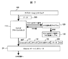
アプリケーションソフトウェア100で送信データ200が生成されると、プロセッサ21は、TCP/IPプロトコルスタック110によって、送信データ200にTCP/UDPヘッダH3、IPヘッダH2、EthernetヘッダH1を生成し、図6に示したEthernetフレームを形成する。この時、TCP/IPプロトコルスタック110は、TCP/UDPポート番号を引数として、COS値取得プログラム120を呼び出す。COS値取得プログラム120は、引数で指定されたTCP/UDPポート番号を検索キーとして、TCP/UDPポート番号−COS変換テーブル130からCOS値を取得し、これをTCP/IPプロトコルスタック110に返す。
When the
TCP/IPプロトコルスタック110は、上記COS値取得プログラム120によって特定されたCOS値をEthernetヘッダH1のタグフィールド613(COSフィールド615)に設定する。尚、送信フレームが、TCP/UDPフレームでなかった場合、TCP/IPプロトコルスタック110は、COS値取得プログラム120を呼び出すことなく、COSフィールド615に「0」を設定する。TCP/IPプロトコルスタック110で生成されたEthernetフレーム60Tは、Ethernetポートインタフェース24を介して、LAN回線に送信される。
The TCP /
図8は、COS値取得プログラム120のフローチャートを示す。
COS値取得プログラム120では、TCP/UDPポート番号−COS変換テーブル130から、引き数で指定されたTCP/UDPポート番号に該当するテーブルエントリを検索する(ステップ121)。検索結果を判定し(122)、検索キーに該当するテーブルエントリが見つかった場合は、このテーブルエントリが示すCOS値をTCP/IPプロトコルスタック110に返す(123)。検索キーに該当するテーブルエントリが見つからなかった場合は、COS値「0」をTCP/IPプロトコルスタック110に返す(124)
図9は、PCにおけるデータフレームの受信動作を示す。
Ethernetポートインタフェース24がLAN回線から受信したEthernetフレーム60Rは、TCP/IPプロトコルスタック110で処理される。TCP/IPプロトコルスタック110では、受信フレーム60RからEthernetヘッダH1、IPヘッダH2、TCP/UDPヘッダH3を除去し、データ部62の内容を受信データ201としてアプリケーションソフトウェア100に渡す。
FIG. 8 shows a flowchart of the COS
The COS
FIG. 9 shows a data frame reception operation in the PC.
The Ethernet frame 60R received from the LAN line by the
図10は、ブリッジにBRおけるEthernetフレームの転送動作を示す。
プロセッサ31は、各Ethernetポートインタフェース、例えば、34−jがLAN回線から受信したEthernetフレーム60Rを、L2経路制御プログラム300に従って処理する。L2経路制御プログラム300では、受信Ethernetフレーム60RのEthernetヘッダH1から、VLAN−ID617とCOS値615とを抽出し、これを引数としてMST instance取得プログラム310を呼び出す。
FIG. 10 shows the transfer operation of the Ethernet frame in the BR on the bridge.
The
MST instance取得プログラム310は、L2経路制御プログラム300が指定したVLAN-IDとCOS値とを検索キーとして、VLAN-ID・COS−MST instance変換テーブル350から、検索キーと対応するMST instanceの識別子353を検索し、これをL2経路制御プログラム300に返す。
The MST
L2経路制御プログラム300は、MST instance識別子353と対応するSTP経路に従って、受信フレームを転送すべきEthernetポートインタフェース34−kを決定し、このインタフェースからEthernetフレーム60Rを送信する。
The L2 path control
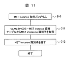
図11は、MST instance取得プログラム310のフローチャートを示す。
MST instance取得プログラム310では、L2経路制御プログラム300から与えられたVLAN−IDとCOSの値との組み合わせを検索キーとして、VLAN-ID・COS−MST instance変換テーブル350を参照し、検索キーに該当するMST instance識別子353を取得し(ステップ311)、取得したMST instance識別子をL2経路制御プログラム300に返す(312)。
FIG. 11 shows a flowchart of the MST
The MST
図12は、本発明が適用されるBridged−VLANの他のネットワーク構成例を示す。
図12のネットワークは、中継網NWに、ゲートウェイGW1を介して、別のLAN#5に接続されている点で、図1と異なる。図12では、ゲートウェイGW1が、LAN#2を介して中継網NWに接続されているが、ゲートウェイGW1は、ブリッジBR2のEthernetポートP23に直接的に接続されてもよい。
FIG. 12 shows another network configuration example of the bridged-VLAN to which the present invention is applied.
The network shown in FIG. 12 is different from that shown in FIG. 1 in that the network shown in FIG. 12 is connected to another
ゲートウェイGW1は、EthernetポートGP1でLAN#2に接続され、EthernetポートGP2でLAN#5と接続されて、LAN#5からの受信フレームをLAN#2に転送すると共に、LAN#2からの受信フレームをLAN#5に転送する。
The gateway GW1 is connected to the
本実施例のゲートウェイGW1は、LAN#5から通信フレームを受信すると、受信フレームが示すTCP/UDPポート番号に従ってCOS値を特定し、これをEthernetヘッダH1のタグフィールドに設定して、受信フレームをLAN#2に転送する。LAN#5には、パーソナルコンピュータPC5が接続されている。パーソナルコンピュータPC5は、SIPクライアントとなっており、SIPサーバで(PC1−3)を経由して、他のSIPクライアント、例えば、PC4と通信する。
When the gateway GW1 of this embodiment receives the communication frame from the
本実施例では、ゲートウェイGW1が、LAN#5からの受信フレームにCOS値を設定するようになっているため、パーソナルコンピュータPC5には、実施例1で説明したCOS値の設定機能、例えば、図2に示したCOS値取得プログラム120とTCP/UDPポート番号−COS変換テーブル130を備える必要はない。
In this embodiment, since the gateway GW1 sets the COS value in the received frame from the
図13は、ゲートウェイGW1の1実施例を示す。
ゲートウェイGW1は、プロセッサ(CPU)41と、主メモリ42と、不揮発性メモリ43と、複数のEthernetポートインタフェース44−1〜44−Nと、これらの要素を相互接続する内部バス45とからなる。不揮発性メモリ43には、本発明が関係するソフトウェアとして、ルーティングテーブル(図示せず)を備えたL3経路制御プログラム400Mと、COS値取得プログラム410Mと、COS値設定テーブル420Mと、TCP/UDPポート番号−COS変換テーブル430Mとが用意されている。ゲートウェイの起動時には、これらのソフトウェアが、主メモリ42にロードされ(400〜430)、プロセッサ41によって実行、あるいは参照される。
FIG. 13 shows an embodiment of the gateway GW1.
The gateway GW1 includes a processor (CPU) 41, a
L3経路制御プログラム400は、LAN#5からEthernetフレームを受信した時、受信フレームからTCP/UDPポート番号を抽出し、COS値取得プログラム410を使用して、TCP/UDPポート番号と対応するCOS値を特定し、このCOS値をEthernetヘッダH1のタグに設定する。L3経路制御プログラム400は、ルーティングテーブルによって、上記Ethernetフレームの出力ポート番号を特定し、受信フレームを出力ポート番号と対応した適切なEthernetポートインタフェースから送出する。
When the L3
COS値取得プログラム410は、COS設定テーブル420とTCP/UDPポート番号−COS変換テーブル430を参照して、L3経路制御プログラム400から指定されたTCP/UDPポート番号に対応するCOS値を取得し、これをL3経路制御プログラム400に返す。
The COS
図14は、COS値設定テーブル420の1例を示す。
COS設定判定テーブル420は、ゲートウェイGW1が備えるEthernetポートの識別番号421毎に、COS値設定の要否を示すフラグ422を示している。ここに示した例では、Ethernetポート番号#1のテーブルエントリで、フラグ422が「1」に設定してある。これは、EthernetポートGP1への転送フレームに対して、COS値を設定すべきことを意味している。
FIG. 14 shows an example of the COS value setting table 420.
The COS setting determination table 420 shows a
図15は、ゲートウェイGW1が備えるTCP/UDPポート番号−COS変換テーブルの430の1例を示す。
TCP/UDPポート番号−COS変換テーブル430は、第1実施例のPCが備えるTCP/UDPポート番号−COS変換テーブル130と同様、TCP/UDPポート番号431とCOS値432との対応関係を示している。
FIG. 15 shows an example of a TCP / UDP port number-COS conversion table 430 included in the gateway GW1.
The TCP / UDP port number-COS conversion table 430 shows the correspondence between the TCP /
図16は、ゲートウェイGW1におけるデータフレームの転送動作を示す。
プロセッサ41は、Ethernetポートインタフェース、例えば、i番目のインタフェース44−iが、Ethernetフレーム60Rを受信すると、受信フレームをL3経路制御プログラム400によって処理する。L3経路制御プログラム400では、受信フレームのヘッダをチェックし、受信フレームがTCP/UDPヘッダH2を持っていた場合、TCP/UDPポート番号を抽出する。また、ルーティングテーブルを参照して、受信フレームの転送先となるEthernetポート番号を特定する。
FIG. 16 shows a data frame transfer operation in the gateway GW1.
When the Ethernet port interface, for example, the i-th interface 44-i receives the Ethernet frame 60R, the processor 41 processes the received frame by the L3 path control
プロセッサ41は、TCP/UDPポート番号とEthernetポート番号を引数として、COS取得プログラム410を呼び出す。TCP/UDPポート番号が抽出されなかった場合、プロセッサ41は、COS取得プログラム410を呼び出すことなく、受信フレームをEthernetポート番号で特定されるEthernetポートインタフェース、例えば、インタフェース44−jから送出する。
The processor 41 calls the
COS取得プログラム410は、COS値設定テーブル420を参照し、指定されたEthernetポート番号と対応するCOS値設定フラグ422を判定する。もし、COS値設定フラグ422が「1」となっていた場合、COS取得プログラム410は、TCP/UDPポート番号−COS変換テーブル(13010)を参照し、指定されたTCP/UDPポート番号と対応するCOS値を取得して、これをL3経路制御プログラム400に返す。
The
L3経路制御プログラム400は、COS取得プログラム410から通知されたCOS値を受信フレームのEthernetヘッダH1(COSフィールド615)に設定し、これを転送先Ethernetポート番号で特定されたEthernetポートインタフェース、例えば、インタフェース44−jから送出する。
The L3 path control
図17は、COS値取得プログラム410のフローチャートを示す。
COS値取得プログラム410では、プロセッサ41は、COS値設定テーブル420から、指定された出力Ethernetポートと対応するCOS値設定フラグ422を読み出す(ステップ411)。COS値設定フラグを判定し(412)もし、フラグが「0」であれば、COS値=「0」をL3経路制御プログラム400に返して(415)、このプログラムを終了する。
FIG. 17 shows a flowchart of the COS
In the COS
COS設定フラグが「1」であれば、プロセッサ41は、TCP/UDPポート番号−COS変換テーブル430から、指定されたTCP/UDPポート番号と対応するテーブルエントリを検索し(413)、該テーブルエントリが示すCOS値432をL3経路制御プログラム400に返して(414)、このプログラムを終了する。 If the COS setting flag is “1”, the processor 41 searches the TCP / UDP port number-COS conversion table 430 for a table entry corresponding to the designated TCP / UDP port number (413). Is returned to the L3 path control program 400 (414), and this program is terminated.
本実施例によれば、パーソナルコンピュータPC5のように、ゲートウェイGW1を介して中継網NWに接続される端末装置には、MSTinstance特定用のCOS値設定機能を必要としないため、LAN#5に収容された複数の端末装置に対して、最適な経路で容易に通信サービスを提供することが可能となる。
According to the present embodiment, a terminal device connected to the relay network NW via the gateway GW1 as in the personal computer PC5 does not require a COS value setting function for specifying MSTinstance, and therefore is accommodated in
BR:ブリッジ、PC:パーソナルコンピュータ、GW:ゲートウェイ、NW:中継網、
21、31、41:プロセッサ、22、32、42:主メモリ、
23、33、43:不揮発性メモリ、
24、34、44:Ethernetポートインタフェース、
100、100M:アプリケーションソフトウェア、
110、110M:TCP/IPプロトコルスタック、
120、120M:COS値取得プログラム、
130:130M:TCP/UDPポート番号−COS変換テーブル、
300、300M:L2経路制御プログラム、
310、310M:MST instance取得プログラム、
350、350M:VLAN-ID・COS-MST instance変換テーブル、
400、400M:L3経路制御プログラム、
410、410M:COS値取得プログラム、
420、420M:COS値設定テーブル、
430、430M:TCP/UDPポート番号−COS変換テーブル。
BR: Bridge, PC: Personal computer, GW: Gateway, NW: Relay network
21, 31, 41: processor, 22, 32, 42: main memory,
23, 33, 43: non-volatile memory,
24, 34, 44: Ethernet port interface,
100, 100M: application software,
110, 110M: TCP / IP protocol stack,
120, 120M: COS value acquisition program,
130: 130M: TCP / UDP port number-COS conversion table,
300, 300M: L2 route control program,
310, 310M: MST instance acquisition program,
350, 350M: VLAN-ID / COS-MST instance conversion table,
400, 400M: L3 route control program,
410, 410M: COS value acquisition program,
420, 420M: COS value setting table,
430, 430M: TCP / UDP port number-COS conversion table.
Claims (8)
上記中継網が、イーサネットフレームを送受信する複数のブリッジからなり、
各ブリッジが、
VLAN識別子とサービスクラス(COS:Class of service)の値との組み合わせに対応してMSTインスタンスの識別子を定義した変換テーブルと、
上記中継網内で、上記変換テーブルで定義されたMSTインスタンス識別子毎にスパニングツリーを形成するための手段とを有し、
上記各ブリッジが、受信フレームのヘッダからVLAN識別子とCOS値とを抽出し、上記変換テーブルによって、上記受信フレームのMSTインスタンス識別子を特定し、該MSTインスタンス識別子をもつスパニングツリーの経路に従って、上記受信フレームを転送することを特徴とするBridged-LAN。 It consists of a relay network in which a plurality of VLANs (Virtual LANs) are formed and a plurality of LANs connected to the relay network. Within the relay network, MST (Multiple Spanning Tree Protocol) consisting of one or a plurality of VLANs In Bridged-LAN where a logical spanning tree is formed for each instance,
The relay network is composed of a plurality of bridges that transmit and receive Ethernet frames,
Each bridge
A conversion table in which identifiers of MST instances are defined corresponding to combinations of VLAN identifiers and service class (COS) values;
Means for forming a spanning tree for each MST instance identifier defined in the conversion table in the relay network,
Each bridge extracts a VLAN identifier and a COS value from the header of the received frame, specifies the MST instance identifier of the received frame by the conversion table, and performs the reception according to the spanning tree path having the MST instance identifier. Bridged-LAN, characterized by transferring frames.
それぞれイーサネットフレームを送受信する複数のポートインタフェースと、
VLAN識別子とサービスクラス(COS:Class of service)の値との組み合わせに対応してMSTインスタンス識別子を定義した変換テーブルと、
上記中継網に、上記変換テーブルで定義されたMSTインスタンス識別子毎にスパニングツリーを形成するための手段と、
上記各ポートインタフェースからイーサネットフレームを受信した時、上記変換テーブルによって、受信フレームのヘッダが示すVLAN識別子とCOSの値との組み合せに対応するMSTインスタンス識別子を特定し、該MSTインスタンス識別子をもつスパニングツリーの経路に従って、上記受信フレームを転送する経路制御部とを備えたことを特徴とする通信ノード装置。 A communication node device installed in a relay network that connects a plurality of LANs (Local Area Networks) by VLAN (Virtual LAN),
Multiple port interfaces each transmitting and receiving Ethernet frames;
A conversion table that defines MST instance identifiers corresponding to combinations of VLAN identifiers and service class (COS) values;
Means for forming a spanning tree for each MST instance identifier defined in the conversion table in the relay network;
When an Ethernet frame is received from each port interface, an MST instance identifier corresponding to a combination of a VLAN identifier and a COS value indicated by the header of the received frame is specified by the conversion table, and a spanning tree having the MST instance identifier A communication node apparatus comprising: a path control unit that forwards the received frame in accordance with the path.
TCP/UDPポート番号とサービスクラス(COS:Class of service)の値との対応関係を示す変換テーブルと、
ネットワークアプリケーションが使用するTCP/UDPポート番号に応じて、上記変換テーブルから、送信フレームに適用すべきCOS値を特定するための手段とを有し、
該端末装置が所属するVLANの識別子と上記特定のCOS値とをヘッダ部に含むイーサネットフレームを上記Bridged-LANに送信することを特徴とする端末装置。 It consists of a relay network in which a plurality of VLANs (Virtual LANs) are formed and a plurality of LANs connected to the relay network. Within the relay network, MST (Multiple Spanning Tree Protocol) consisting of one or a plurality of VLANs A terminal device connected to a bridged-LAN in which a logical spanning tree is formed for each instance,
A conversion table indicating a correspondence relationship between a TCP / UDP port number and a value of a class of service (COS);
Means for specifying a COS value to be applied to a transmission frame from the conversion table according to a TCP / UDP port number used by a network application;
A terminal device, characterized in that an Ethernet frame including a header part including an identifier of a VLAN to which the terminal device belongs and the specific COS value is transmitted to the Bridged-LAN.
それぞれがポート番号によって識別される複数のポートインタフェースと、
TCP/UDPポート番号とサービスクラス(COS:Class of service)の値との対応関係を示す変換テーブルと、
ポート番号と対応してCOS値設定の要否を示すフラグ情報を記憶したCOS値設定テーブルと、
上記各ポートインタフェースからイーサネットフレームを受信した時、上記COS値設定テーブルから、受信フレームの転送先となるポート番号と対応するフラグ情報を検索し、該フラグ情報がCOS値設定要を示す場合、上記変換テーブルから、上記受信フレームのTCP/UDPポート番号と対応するCOS値を検索し、該COS値を上記受信フレームのヘッダ部に設定して、受信フレームを上記転送先ポート番号で特定されるポートインタフェースに転送する経路制御手段とを備えたことを特徴とするゲートウェイ装置。 It consists of a relay network in which a plurality of VLANs (Virtual LANs) are formed and a plurality of LANs connected to the relay network. Within the relay network, MST (Multiple Spanning Tree Protocol) consisting of one or a plurality of VLANs A gateway device connected between a bridged-LAN in which a logical spanning tree is formed for each instance and at least one LAN,
Multiple port interfaces, each identified by a port number;
A conversion table indicating a correspondence relationship between a TCP / UDP port number and a value of a class of service (COS);
A COS value setting table storing flag information indicating the necessity of COS value setting corresponding to the port number;
When an Ethernet frame is received from each of the port interfaces, flag information corresponding to the port number that is the transfer destination of the received frame is searched from the COS value setting table, and when the flag information indicates that COS value setting is required, The COS value corresponding to the TCP / UDP port number of the received frame is searched from the conversion table, the COS value is set in the header portion of the received frame, and the received frame is specified by the transfer destination port number. A gateway apparatus comprising a path control means for transferring to an interface.
Priority Applications (3)
| Application Number | Priority Date | Filing Date | Title |
|---|---|---|---|
| JP2006330992A JP4878545B2 (en) | 2006-12-07 | 2006-12-07 | Bridged-LAN and communication node device |
| US11/780,070 US7710985B2 (en) | 2006-12-07 | 2007-07-19 | Bridged LAN and communication node therefor |
| CN2007101383932A CN101197751B (en) | 2006-12-07 | 2007-08-01 | Bridged LAN and communication node therefor |
Applications Claiming Priority (1)
| Application Number | Priority Date | Filing Date | Title |
|---|---|---|---|
| JP2006330992A JP4878545B2 (en) | 2006-12-07 | 2006-12-07 | Bridged-LAN and communication node device |
Publications (3)
| Publication Number | Publication Date |
|---|---|
| JP2008147882A JP2008147882A (en) | 2008-06-26 |
| JP2008147882A5 JP2008147882A5 (en) | 2009-07-09 |
| JP4878545B2 true JP4878545B2 (en) | 2012-02-15 |
Family
ID=39497888
Family Applications (1)
| Application Number | Title | Priority Date | Filing Date |
|---|---|---|---|
| JP2006330992A Expired - Fee Related JP4878545B2 (en) | 2006-12-07 | 2006-12-07 | Bridged-LAN and communication node device |
Country Status (3)
| Country | Link |
|---|---|
| US (1) | US7710985B2 (en) |
| JP (1) | JP4878545B2 (en) |
| CN (1) | CN101197751B (en) |
Families Citing this family (12)
| Publication number | Priority date | Publication date | Assignee | Title |
|---|---|---|---|---|
| JP4934116B2 (en) * | 2008-08-15 | 2012-05-16 | 日本電信電話株式会社 | Node, packet transfer method and program thereof |
| WO2011093882A1 (en) * | 2010-01-29 | 2011-08-04 | Hewlett-Packard Development Company, L.P. | Configuration of network links in a virtual connection environment |
| US8873431B1 (en) * | 2010-04-08 | 2014-10-28 | Adtran, Inc. | Communications system and method for maintaining topology in a VLAN environment |
| US8718071B2 (en) | 2010-09-10 | 2014-05-06 | Futurewei Technologies, Inc. | Method to pass virtual local area network information in virtual station interface discovery and configuration protocol |
| US9397900B2 (en) * | 2010-09-27 | 2016-07-19 | Coriant Operations, Inc. | Methods and apparatus for sharing counter resources between CoS/priority or/and between EVC/VLAN to support frame loss measurement |
| US9124524B2 (en) * | 2011-06-29 | 2015-09-01 | Broadcom Corporation | System and method for priority based flow control between nodes |
| CN102437963B (en) * | 2011-12-31 | 2014-11-19 | 华为技术有限公司 | Routing creation method and router |
| JP5910170B2 (en) * | 2012-03-01 | 2016-04-27 | 株式会社リコー | Network relay device and network topology construction method |
| CN103501274B (en) * | 2013-09-24 | 2017-09-12 | 神州数码网络(北京)有限公司 | Flow load sharing method and device in a kind of multilink transparent internet |
| WO2016018410A1 (en) * | 2014-07-31 | 2016-02-04 | Hewlett-Packard Development Company, Lp | Encapsulation packet with class of service encoding |
| DE102019114305A1 (en) * | 2019-05-28 | 2020-12-03 | Beckhoff Automation Gmbh | Data transfer method, data structure, automation network and unlocker |
| CN110932911B (en) * | 2019-12-12 | 2022-07-08 | 西安邮电大学 | Method for generating priority of switch in multiple spanning tree domains |
Family Cites Families (11)
| Publication number | Priority date | Publication date | Assignee | Title |
|---|---|---|---|---|
| US6801506B1 (en) * | 1999-03-31 | 2004-10-05 | Cisco Technology, Inc. | Method and apparatus for providing fast spanning tree re-starts |
| US6515969B1 (en) * | 1999-03-01 | 2003-02-04 | Cisco Technology, Inc. | Virtual local area network membership registration protocol for multiple spanning tree network environments |
| JP3614118B2 (en) * | 2001-05-23 | 2005-01-26 | 日本電気株式会社 | Node device of ring system, multi-spanning tree construction system using the same, and method thereof |
| JP4651244B2 (en) * | 2001-09-17 | 2011-03-16 | 富士通株式会社 | Switch and bridged network |
| US7212536B2 (en) * | 2001-12-27 | 2007-05-01 | Alcatel-Lucent Canada Inc. | User priority mapping in bridged VLANS |
| JP2004080323A (en) * | 2002-08-16 | 2004-03-11 | Fujitsu Ltd | Lan switching method and lan switch |
| WO2004075486A1 (en) * | 2003-02-19 | 2004-09-02 | Fujitsu Limited | Virtual lan building device |
| WO2005057863A1 (en) * | 2003-12-12 | 2005-06-23 | Fujitsu Limited | Data transmission apparatus |
| US8422500B2 (en) * | 2004-07-02 | 2013-04-16 | Rockstar Consortium Us Lp | VLAN support of differentiated services |
| US8194656B2 (en) * | 2005-04-28 | 2012-06-05 | Cisco Technology, Inc. | Metro ethernet network with scaled broadcast and service instance domains |
| US20080019385A1 (en) * | 2005-12-30 | 2008-01-24 | Huawei Technologies Co., Inc. (Usa) | System and method of mapping between local and global service instance identifiers in provider networks |
-
2006
- 2006-12-07 JP JP2006330992A patent/JP4878545B2/en not_active Expired - Fee Related
-
2007
- 2007-07-19 US US11/780,070 patent/US7710985B2/en active Active
- 2007-08-01 CN CN2007101383932A patent/CN101197751B/en not_active Expired - Fee Related
Also Published As
| Publication number | Publication date |
|---|---|
| CN101197751B (en) | 2011-02-02 |
| US7710985B2 (en) | 2010-05-04 |
| US20080137557A1 (en) | 2008-06-12 |
| CN101197751A (en) | 2008-06-11 |
| JP2008147882A (en) | 2008-06-26 |
Similar Documents
| Publication | Publication Date | Title |
|---|---|---|
| JP4878545B2 (en) | Bridged-LAN and communication node device | |
| CN109194660B (en) | Network access method and device of mobile terminal | |
| CN103200069B (en) | A kind of method and apparatus of Message processing | |
| US7664119B2 (en) | Method and apparatus to perform network routing | |
| KR102054338B1 (en) | Routing vlan tagged packets to far end addresses of virtual forwarding instances using separate administrations | |
| US7920548B2 (en) | Intelligent switching for secure and reliable voice-over-IP PBX service | |
| US8588081B2 (en) | Monitoring a flow set to detect faults | |
| CN101185296B (en) | Method for establishing multi-line between local network and remote network as well as relevant device | |
| WO2013145167A1 (en) | Lan multiplexer apparatus | |
| WO2018059284A1 (en) | Data transmission method and network equipment | |
| CN108574616A (en) | A kind of method, equipment and the system of processing routing | |
| WO2016054956A1 (en) | Load sharing method and device | |
| US8699492B2 (en) | Method and apparatus for simulating IP multinetting | |
| JP2008147882A5 (en) | ||
| WO2008046359A1 (en) | Method and apparatus for isolating the different virtual local area network services | |
| WO2020135381A1 (en) | Packet processing method, device, and system | |
| US20220385497A1 (en) | Method for network slices to share uplink port, apparatus, and storage medium | |
| KR20180104377A (en) | Method for inter-cloud virtual networking over packet optical transport network | |
| CN108259351B (en) | Data transmission method suitable for wide-band and narrow-band channel hybrid network | |
| WO2022160665A1 (en) | Packet forwarding method, packet processing method, and device | |
| US20110222541A1 (en) | Network System, Edge Node, and Relay Node | |
| RU2310994C2 (en) | Traffic division filter | |
| JP2002204252A (en) | System for converting overlapping private address | |
| JP2006279771A (en) | Method and program for packet transmission | |
| WO2006036463A2 (en) | A communication network, communication elements and methods of communicating data packets therefor |
Legal Events
| Date | Code | Title | Description |
|---|---|---|---|
| A521 | Request for written amendment filed |
Free format text: JAPANESE INTERMEDIATE CODE: A523 Effective date: 20090521 |
|
| A621 | Written request for application examination |
Free format text: JAPANESE INTERMEDIATE CODE: A621 Effective date: 20090521 |
|
| A711 | Notification of change in applicant |
Free format text: JAPANESE INTERMEDIATE CODE: A712 Effective date: 20100115 |
|
| TRDD | Decision of grant or rejection written | ||
| A01 | Written decision to grant a patent or to grant a registration (utility model) |
Free format text: JAPANESE INTERMEDIATE CODE: A01 Effective date: 20111122 |
|
| A01 | Written decision to grant a patent or to grant a registration (utility model) |
Free format text: JAPANESE INTERMEDIATE CODE: A01 |
|
| A61 | First payment of annual fees (during grant procedure) |
Free format text: JAPANESE INTERMEDIATE CODE: A61 Effective date: 20111128 |
|
| R150 | Certificate of patent or registration of utility model |
Ref document number: 4878545 Country of ref document: JP Free format text: JAPANESE INTERMEDIATE CODE: R150 Free format text: JAPANESE INTERMEDIATE CODE: R150 |
|
| FPAY | Renewal fee payment (event date is renewal date of database) |
Free format text: PAYMENT UNTIL: 20141209 Year of fee payment: 3 |
|
| LAPS | Cancellation because of no payment of annual fees |