JP4877550B2 - Device for detecting and characterizing living tissue - Google Patents
Device for detecting and characterizing living tissue Download PDFInfo
- Publication number
- JP4877550B2 JP4877550B2 JP2006521619A JP2006521619A JP4877550B2 JP 4877550 B2 JP4877550 B2 JP 4877550B2 JP 2006521619 A JP2006521619 A JP 2006521619A JP 2006521619 A JP2006521619 A JP 2006521619A JP 4877550 B2 JP4877550 B2 JP 4877550B2
- Authority
- JP
- Japan
- Prior art keywords
- pixel
- frequency band
- image
- green
- energy
- Prior art date
- Legal status (The legal status is an assumption and is not a legal conclusion. Google has not performed a legal analysis and makes no representation as to the accuracy of the status listed.)
- Active
Links
- 238000000034 method Methods 0.000 claims description 14
- 230000000295 complement effect Effects 0.000 claims description 10
- 239000000126 substance Substances 0.000 claims description 7
- 230000001678 irradiating effect Effects 0.000 claims description 6
- 230000003071 parasitic effect Effects 0.000 claims description 5
- 230000003595 spectral effect Effects 0.000 claims description 5
- 238000001228 spectrum Methods 0.000 claims description 5
- 229920006395 saturated elastomer Polymers 0.000 claims description 3
- 238000002189 fluorescence spectrum Methods 0.000 claims description 2
- 230000003321 amplification Effects 0.000 claims 2
- 238000003199 nucleic acid amplification method Methods 0.000 claims 2
- 238000005286 illumination Methods 0.000 claims 1
- 230000005855 radiation Effects 0.000 claims 1
- 210000001519 tissue Anatomy 0.000 description 40
- 210000003298 dental enamel Anatomy 0.000 description 8
- 238000004020 luminiscence type Methods 0.000 description 7
- 239000003086 colorant Substances 0.000 description 5
- 238000001514 detection method Methods 0.000 description 5
- 230000003902 lesion Effects 0.000 description 3
- 210000004400 mucous membrane Anatomy 0.000 description 3
- 208000006558 Dental Calculus Diseases 0.000 description 2
- 208000002925 dental caries Diseases 0.000 description 2
- 230000006866 deterioration Effects 0.000 description 2
- 238000001727 in vivo Methods 0.000 description 2
- 238000005259 measurement Methods 0.000 description 2
- 230000008354 tissue degradation Effects 0.000 description 2
- 229910052724 xenon Inorganic materials 0.000 description 2
- FHNFHKCVQCLJFQ-UHFFFAOYSA-N xenon atom Chemical compound [Xe] FHNFHKCVQCLJFQ-UHFFFAOYSA-N 0.000 description 2
- 201000009030 Carcinoma Diseases 0.000 description 1
- 206010028980 Neoplasm Diseases 0.000 description 1
- 208000004188 Tooth Wear Diseases 0.000 description 1
- 238000005299 abrasion Methods 0.000 description 1
- 238000010521 absorption reaction Methods 0.000 description 1
- 238000010171 animal model Methods 0.000 description 1
- 238000003556 assay Methods 0.000 description 1
- 230000002238 attenuated effect Effects 0.000 description 1
- 229960000074 biopharmaceutical Drugs 0.000 description 1
- 201000011510 cancer Diseases 0.000 description 1
- 230000006378 damage Effects 0.000 description 1
- 230000007547 defect Effects 0.000 description 1
- 238000003745 diagnosis Methods 0.000 description 1
- 238000010586 diagram Methods 0.000 description 1
- 239000000975 dye Substances 0.000 description 1
- 238000000295 emission spectrum Methods 0.000 description 1
- 238000002474 experimental method Methods 0.000 description 1
- 238000001917 fluorescence detection Methods 0.000 description 1
- 230000004054 inflammatory process Effects 0.000 description 1
- 229910052500 inorganic mineral Inorganic materials 0.000 description 1
- 239000011707 mineral Substances 0.000 description 1
- 210000002200 mouth mucosa Anatomy 0.000 description 1
- 230000003287 optical effect Effects 0.000 description 1
- 210000000496 pancreas Anatomy 0.000 description 1
- 230000001575 pathological effect Effects 0.000 description 1
- 102000004169 proteins and genes Human genes 0.000 description 1
- 108090000623 proteins and genes Proteins 0.000 description 1
- 230000035945 sensitivity Effects 0.000 description 1
- 238000000926 separation method Methods 0.000 description 1
- 210000004872 soft tissue Anatomy 0.000 description 1
- 210000002784 stomach Anatomy 0.000 description 1
Images
Classifications
-
- A—HUMAN NECESSITIES
- A61—MEDICAL OR VETERINARY SCIENCE; HYGIENE
- A61B—DIAGNOSIS; SURGERY; IDENTIFICATION
- A61B5/00—Measuring for diagnostic purposes; Identification of persons
- A61B5/0059—Measuring for diagnostic purposes; Identification of persons using light, e.g. diagnosis by transillumination, diascopy, fluorescence
- A61B5/0082—Measuring for diagnostic purposes; Identification of persons using light, e.g. diagnosis by transillumination, diascopy, fluorescence adapted for particular medical purposes
- A61B5/0088—Measuring for diagnostic purposes; Identification of persons using light, e.g. diagnosis by transillumination, diascopy, fluorescence adapted for particular medical purposes for oral or dental tissue
-
- A—HUMAN NECESSITIES
- A61—MEDICAL OR VETERINARY SCIENCE; HYGIENE
- A61B—DIAGNOSIS; SURGERY; IDENTIFICATION
- A61B5/00—Measuring for diagnostic purposes; Identification of persons
-
- A—HUMAN NECESSITIES
- A61—MEDICAL OR VETERINARY SCIENCE; HYGIENE
- A61K—PREPARATIONS FOR MEDICAL, DENTAL OR TOILETRY PURPOSES
- A61K49/00—Preparations for testing in vivo
-
- G—PHYSICS
- G06—COMPUTING; CALCULATING OR COUNTING
- G06T—IMAGE DATA PROCESSING OR GENERATION, IN GENERAL
- G06T5/00—Image enhancement or restoration
- G06T5/10—Image enhancement or restoration by non-spatial domain filtering
-
- G06T5/94—
-
- G—PHYSICS
- G06—COMPUTING; CALCULATING OR COUNTING
- G06T—IMAGE DATA PROCESSING OR GENERATION, IN GENERAL
- G06T7/00—Image analysis
- G06T7/0002—Inspection of images, e.g. flaw detection
- G06T7/0012—Biomedical image inspection
-
- G—PHYSICS
- G06—COMPUTING; CALCULATING OR COUNTING
- G06T—IMAGE DATA PROCESSING OR GENERATION, IN GENERAL
- G06T7/00—Image analysis
- G06T7/40—Analysis of texture
- G06T7/41—Analysis of texture based on statistical description of texture
- G06T7/42—Analysis of texture based on statistical description of texture using transform domain methods
-
- G—PHYSICS
- G06—COMPUTING; CALCULATING OR COUNTING
- G06T—IMAGE DATA PROCESSING OR GENERATION, IN GENERAL
- G06T2207/00—Indexing scheme for image analysis or image enhancement
- G06T2207/10—Image acquisition modality
- G06T2207/10016—Video; Image sequence
-
- G—PHYSICS
- G06—COMPUTING; CALCULATING OR COUNTING
- G06T—IMAGE DATA PROCESSING OR GENERATION, IN GENERAL
- G06T2207/00—Indexing scheme for image analysis or image enhancement
- G06T2207/10—Image acquisition modality
- G06T2207/10024—Color image
-
- G—PHYSICS
- G06—COMPUTING; CALCULATING OR COUNTING
- G06T—IMAGE DATA PROCESSING OR GENERATION, IN GENERAL
- G06T2207/00—Indexing scheme for image analysis or image enhancement
- G06T2207/30—Subject of image; Context of image processing
- G06T2207/30004—Biomedical image processing
- G06T2207/30036—Dental; Teeth
Description
この発明は、生体組織の密度、構造又は化学組成における相違を検知し、位置付けし、特徴づける方法とそのための装置に関するものである。 The present invention relates to a method and apparatus for detecting, locating and characterizing differences in density, structure or chemical composition of living tissue.
従来の技術においては、内因性発色団又は投与された染料又は外因性発色団を含む組織の自己蛍光を用いて、病理学的なものであると否とに拘らず、生理学的又は組織学的起源の組織の相違を検知し又は実証するための各種の方法が提案されている。 In the prior art, the autofluorescence of tissues containing endogenous chromophores or administered dyes or exogenous chromophores, whether or not pathological, is physiological or histological. Various methods have been proposed for detecting or demonstrating differences in tissue of origin.
これによって、観察された領域が健康であるか又はダメージを受けているかに基づく発色団コンテントの相違による原理に基づき、生体組織の蛍光をリアルタイムでのマッピングすることが可能になっている。 This makes it possible to map the fluorescence of living tissue in real time based on the principle of chromophore content differences based on whether the observed area is healthy or damaged.
前記方法は、歯のエナメル質のような硬い組織又は皮膚や口腔粘膜のような柔らかな組織におけるむしばまれたダメージを直接観察したり、又は、内視鏡ルートで胸部または胃の内部粘膜を観察するために使用されている。 The method directly observes injured damage in hard tissues such as tooth enamel or soft tissues such as skin and oral mucosa, or the internal mucous membrane of the chest or stomach with an endoscopic route. Used to observe.
また前記組織がきめられた波長のモノクロ光線により照射されて、この光線が異なる波長のルミネセンスによりフィードバックされるようにして、組織の相違を検知し、特徴づける各種の方法も提案されている。 Various methods have also been proposed for detecting and characterizing tissue differences by irradiating the tissue with a monochromatic light beam of a determined wavelength and feeding back the light beam with luminescence of a different wavelength.
この原理によれば、そして、一例ではあるが、歯の健康な部分と虫歯部分とにより放射されるルミネセンスの強度を、これら特定の波長それぞれを測定することにより、特に、算術計算を用いてこれら二つの強度における相違を計算することで、虫歯の存在をみつけたり、得られた値に関する組織の相違又は表面の悪化を明示することができる。 According to this principle, and by way of example, the intensity of the luminescence emitted by the healthy and carious parts of the tooth is measured by measuring each of these specific wavelengths, in particular using arithmetic calculations. By calculating the difference in these two intensities, the presence of caries can be found, or the difference in tissue or surface deterioration with respect to the value obtained can be demonstrated.
前記した方法は、また、動物をモデルにした膵臓の炎症プロセスの生体内検知にも使用されており、この検知にあっては、青色と赤色との間のスペクトルと明暗度を比較することで健康な組織といためられた組織とが顕著に識別される。 The method described above has also been used for in vivo detection of inflammatory processes of the pancreas using animal models, by comparing the spectrum and intensity between blue and red. Healthy tissue and stigmatized tissue are markedly distinguished.
文献においては、別の用途も分かっており、特に、気管−気管支構造の癌の生体内検知に適用されており、ここでは、組織が異常形成症状態から癌症状態へ変わるとき、気管支の自己蛍光がモディファイされるということが分かっている。このケースにおいては、病変部が約500nmの減衰した緑色蛍光発光になり、約600nmの赤色スペクトルバンドに増加することが分かっている。 In the literature, other uses are also known, in particular applied to the in vivo detection of cancer of the tracheo-bronchial structure, where bronchial autofluorescence when the tissue changes from an dysplastic state to a cancerous state. Is known to be modified. In this case, it has been found that the lesion has an attenuated green fluorescence emission of about 500 nm and increases to a red spectral band of about 600 nm.
これと同じ理屈が眼科学にも使用され、水晶体の透明度のアッセイに適用されて、蛍光発光により蛋白質が光酸化されたことが確認できるようになっている。 This same theory is used in ophthalmology and has been applied to the lens transparency assay to confirm that the protein has been photooxidized by fluorescence.
前記の適用用途は、スペクトル分離フィルター類をもつ通常の光学手段を使用する装置類に頼っている。 Such applications rely on equipment that uses conventional optical means with spectral separation filters.
前記フィルター類は、扱いにくく、脆弱で高価な装置類を必要とする欠点をもっている。光の照度を強くしなければならないために、シグナル対ノイズのレシオを損ね、関連するシグナルの検知をかくしてしまうようになる寄生的な蛍光発光が行われてしまうことになる。 The filters have the disadvantage of being cumbersome and requiring fragile and expensive equipment. Since the illuminance of the light must be increased, parasitic fluorescence is emitted that impairs the signal-to-noise ratio and thus uncovers the associated signal.
この発明の目的は、生体組織の構造的相違又は別の相違を検知し、位置決めし、特徴づけることを確実に行うことができる方法と装置を提供する点にあり、この装置は、簡単な構造、低価格であり、扱いやすく、組織表面に作用し、測定を乱す種々の不知の要因に関連する種々異なる人為構造をなくすことができるものである。 It is an object of the present invention to provide a method and apparatus that can reliably detect, position and characterize structural differences or other differences in living tissue, which apparatus has a simple structure. It is low cost, easy to handle, eliminates the various artifacts associated with various unknown factors that affect the tissue surface and disturb the measurement.
したがって、この発明の主題は、決定された第1の周波数帯域において照射を連続させることで、前記組織を蛍光発光。自己蛍光又は第2の周波数帯域におけるルミネセンスさせることができる生体組織の密度及び/又は構造及び/又は化学的組成における相違を検知し、かつ、位置決めするための方法であって、以下の工程を備えることを特徴とするものである: Therefore, the subject of the present invention is to fluoresce the tissue by continuously irradiating in the determined first frequency band. A method for detecting and locating differences in density and / or structure and / or chemical composition of biological tissue capable of autofluorescence or luminescence in a second frequency band, comprising the following steps: It is characterized by comprising:
−補色フィルター類を有する画素のモザイクをもつイメージセンサーを備えたカラービデオ手段を用いて、このようにして照射した生体組織のイメージを捕捉し、
−このようにして得られたイメージの各ポイントに対しては;
a)各画素により、受けられたエネルギーに関するデータを集め、生体組織のイメージを再構築し、
b)第2の周波数帯域で受けたエネルギーに相当するシグナルを増幅して、得られたイメージにおける生体組織の前記相違を特徴づけるか又は明らかになるようにする。
Using a color video means with an image sensor with a mosaic of pixels with complementary color filters, to capture an image of the irradiated biological tissue in this way,
-For each point of the image thus obtained;
a) Collect data on the energy received by each pixel, reconstruct the image of the living tissue,
b) Amplifying the signal corresponding to the energy received in the second frequency band so as to characterize or reveal the difference of the biological tissue in the obtained image.
この発明によれば、周波数の第2の帯域で集められたデータは、処理されて、この周波数の第2の帯域に相当するカラー以外のカラーで得られた構造上の相違を特徴づけるようになっている。 According to the present invention, the data collected in the second band of frequencies is processed so as characterizing the difference on which the structure obtained by the color other than the color to be equivalent to a second band of the frequency It has become.
この発明のさらなる主題は、生体組織の密度及び/又は構造及び/又は化学組成における相違を検知し、位置決めする装置であって、以下を備えることを特徴とする: A further subject matter of the invention is a device for detecting and locating differences in density and / or structure and / or chemical composition of living tissue, characterized in that it comprises:
−第1の決められた周波数帯域にある光線を生体組織に連続照射し、前記組織に第2の帯域の周波数における蛍光発光現象を生起させることができるようする手段、
−補色フィルター類が備えられた画素のモザイクをもつイメージセンサー類が備えられているカラービデオ手段、
−このようにして得られた各イメージポイントに対し、各画素により受けられたエネルギーに関連するカラーデータを集め、生体組織のイメージを再構築することができる捕捉及び計算手段、
−第2帯域の周波数で受けたエネルギーに相当するシグナルを増幅し、得られたイメージにおける生体組織の前記相違を特徴づけるか又は明らかにする手段。
Means for continuously irradiating a living tissue with a light beam in a first determined frequency band, and causing the tissue to cause a fluorescence emission phenomenon at a frequency in a second band;
Color video means provided with image sensors having a mosaic of pixels provided with complementary color filters;
-For each image point thus obtained, a capture and calculation means capable of collecting color data relating to the energy received by each pixel and reconstructing an image of living tissue;
Means for amplifying a signal corresponding to the energy received at the frequency of the second band and characterizing or revealing said differences in biological tissue in the obtained image;
この装置は、また、周波数の第2の帯域で集められたデータを処理して、この周波数の第2の帯域に相当するカラー以外のカラーで得られた構造上の相違を特徴づける手段を備えている。 The apparatus also processes the second data gathered in a band of frequencies, a means for characterizing the differences on the second band obtained in the phase equivalent to the non-color color structure of the frequency I have.
この発明のさらなる主題は、第1の決められた周波数帯域にある光線を生体組織に連続照射し、前記組織に第2の帯域において周波数蛍光発光、自己蛍光又はルミネセンス現象を生じさせて、生体組織の密度及び/又は構造及び/又は化学組成における相違を検知し、位置決めする方法であって、以下の工程を備えることを特徴とする: A further subject matter of the present invention is to continuously irradiate a living tissue with a light beam in a first determined frequency band, and cause the tissue to generate a frequency fluorescence emission, autofluorescence or luminescence phenomenon in a second band, A method for detecting and positioning differences in tissue density and / or structure and / or chemical composition, characterized in that it comprises the following steps:
−モノクロームイメージセンサー類、即ち、ルミネセンスセンサー及び少なくとも1つのセンサーで明らかにした相違を検知する間発光される蛍光のカラーに相当するカラーのフィルターを備えているセンサーからなるイメージ捕捉手段を用いて、このようにして照射した生体組織のイメージを捕捉し、
−このようにして得られたイメージの各ポイントに対しては;
a)各画素により受けられたエネルギーに関するデータを集め、生体組織のイメージを再構築し、
b)周波数の第2の帯域で受けたエネルギーに相当するシグナルを増幅して、得られたイメージにおける生体組織の前記相違を特徴づけるか又は明らかになるようにする。
Using monochrome image sensors, i.e. an image capturing means comprising a luminescence sensor and a sensor with a filter of a color corresponding to the color of the fluorescence emitted while detecting the difference revealed by the at least one sensor; , Capturing the image of the irradiated biological tissue in this way,
-For each point of the image thus obtained;
a) Collect data on the energy received by each pixel, reconstruct the image of living tissue,
b) amplifying the signals corresponding to the energy received in the second band of frequencies, resulting by the difference ing apparent or characterize the biological tissue in the image Unisuru.
この発明のさらなる主題は、生体組織の密度及び/又は構造及び/又は化学組成における相違を検知し、位置決めする装置であって、以下を備えることを特徴とする: A further subject matter of the invention is a device for detecting and locating differences in density and / or structure and / or chemical composition of living tissue, characterized in that it comprises:
−第1の決められた周波数帯域にある光線を生体組織に連続照射し、前記組織に第2の帯域の周波数における蛍光発光現象を生起させることができるようする手段、
−モノクロームイメージセンサー類、即ち、ルミネセンスセンサー及び少なくとも1つのセンサーで明らかにした相違を検知する間、発光される蛍光のカラーに相当するカラーのフィルターを備えているセンサーからなるイメージ捕捉手段、
−このようにして得られた各イメージポイントに対し、各画素により受けられたエネルギーに関連するカラーデータを集め、生体組織のイメージを再構築することができる捕捉及び計算手段、
−第2帯域の周波数で受けたエネルギーに相当するシグナルを増幅し、得られたイメージにおける生体組織の前記相違を特徴づけるか又は明らかにする手段。
Means for continuously irradiating a living tissue with a light beam in a first determined frequency band, and causing the tissue to cause a fluorescence emission phenomenon at a frequency in a second band;
An image capturing means comprising monochrome image sensors, i.e. sensors comprising a filter of a color corresponding to the color of the fluorescence emitted while detecting the difference revealed by the luminescence sensor and the at least one sensor;
-For each image point thus obtained, a capture and calculation means capable of collecting color data relating to the energy received by each pixel and reconstructing an image of living tissue;
Means for amplifying a signal corresponding to the energy received at the frequency of the second band and characterizing or revealing said differences in biological tissue in the obtained image;
この発明が特に興味をひく点は、従来の技術装置とは異なり、モノクローム光源に頼ることなく、第1に前記光源により供給されたエネルギーの大部分を使用し、ついで、可視範囲内の光線帯域を使用して、検査する組織のイメージ(歯科領域では歯のイメージ又は他の領域では、粘膜、皮膚、眼などのイメージ)を得る。 Of particular interest to this invention is that, unlike prior art devices, it does not rely on a monochrome light source, but first uses the majority of the energy supplied by the light source, and then the light band within the visible range. Is used to obtain an image of the tissue to be examined (a dental image in the dental region or an image of mucous membranes, skin, eyes, etc. in other regions).
この発明の一つの実施例において、そして、例えば、歯のエナメル質部分のような硬い組織を観察する事例の関連において、第2の周波数帯域が原色(この例では赤色)の中心にある場合、ビデオカラー手段のCCD(電荷結合素子)センサー類には、複数の画素のそれぞれにフィルターが設けられていて、これらフィルターのカラーは、補色、即ち、黄色、マゼンタおよびシアンの色が好ましい。前記補色のフィルター類を使用する事は、興味をひく点であって、これは、まず第1には、これらフィルターの吸収波長帯域の範囲、したがって、前記センサー類の感受性が、前記原色、即ち、前記補色のそれぞれに関連した原色よりも大きく、したがって、第2には、1つのシグナル、即ち、前記原色に関連したシグナルのみに作用するものではなく、2つのシグナル、即ち、各原色に関連した補色の2つのシグナルに作用させることが可能になり、したがって、使用されているフィルターの管理を改善することができる点である。 In one embodiment of the invention, and in the context of observing hard tissue such as, for example, the enamel portion of a tooth, if the second frequency band is centered on the primary color (red in this example) the CCD (charge coupled device) sensor over such video color means, have the filter is provided in each of a plurality of pixels, these filters colors are complementary colors, i.e., yellow, magenta and cyan colors are preferred. The use of complementary color filters is of interest because, first of all, the range of the absorption wavelength band of these filters, and thus the sensitivity of the sensors, is the primary color, i.e. , Larger than the primary color associated with each of the complementary colors, and therefore secondly, it does not affect only one signal, ie, the signal associated with the primary color, but two signals, ie, associated with each primary color It is possible to act on the two signals of the complementary colors, thus improving the management of the filters used.
この発明の実施例を添付の図面を参照しながら、限定されない実施例として、以下に記載する。 Embodiments of the present invention will be described below as non-limiting embodiments with reference to the accompanying drawings.
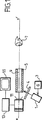
図1に図示の発明装置は、電流ゼネレータ3により電流が供給されるキセノンランプ1からなる。モノクロでなく、ランプ1により供給される光線は、前記ランプから発光されるとフィルタ4により濾光され、紫外線帯域から可視領域に近い帯域におよぶ光帯域を維持することができるようになっている。これらの光線は、導波管5を通り、生体組織、この場合には、患者の歯7を照射し続ける。導波管5は、カラービデオカメラ11が前記歯7を写すことができる軸xx’をもつ中央、長さ方向チャンネルがある。
The inventive device shown in FIG. 1 comprises a xenon lamp 1 to which a current is supplied by a current generator 3. A light beam supplied by the lamp 1 instead of monochrome is filtered by the filter 4 when emitted from the lamp, and can maintain a light band extending from the ultraviolet band to the band close to the visible region. . These rays continue to illuminate the biological tissue, in this case the patient's teeth 7, through the waveguide 5. The waveguide 5 has a central, longitudinal channel with an axis xx 'through which the
前記カメラ11は、シグナル処理手段13に接続し、これらの手段は、ビデオディスプレイ手段15に接続している。
The
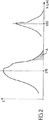
この実施例においては、フィルター4は、波長帯域の中心が約370nmとなる波長を透過し、この周波数帯域の一部は,図2に示すように可視範囲に位置する部分Aを備える。 In this embodiment, the filter 4 is transmitted through the wavelength center of a wavelength band of about 3 70 nm, a part of the frequency band has a portion A located in the visible range, as shown in FIG.
このような照射によって前記歯のミネラル成分、即ちエナメル質が緑色と青色範囲にある蛍光発光することが知られている。 It is known that such irradiation causes fluorescent emission of the tooth mineral component, that is, enamel, in the green and blue range.
また、歯の摩耗による部分的な劣化が進行しだした歯のエナメル質部分は、650nmの範囲で蛍光発光、換言すれば、赤色発光することも分かっている。 It has also been found that the enamel portion of the tooth where partial deterioration due to tooth wear has started to emit fluorescence in the range of 650 nm, in other words, red.
この発明によれば、カラービデオカメラ11を用いて、いくつかのスペクトル帯域で合成されたイメージを記録するものであり、該イメージは、即ち、以下のものである:
According to the present invention, a
−照射スペクトルの可視部分により歯に作られた照射から生じる歯のイメージ、
−照射スペクトルにより発生の紫外線領域における照射による歯のエナメル質から導き出される歯のイメージ、
−摩耗による歯のエナメル質の劣化部分から発光の蛍光発光イメージ(赤色、即ち、約650nmあたりのもの)。
-An image of the tooth resulting from the irradiation made on the tooth by the visible part of the irradiation spectrum,
The image of the tooth derived from the enamel of the tooth by irradiation in the ultraviolet region generated by the irradiation spectrum,
-Fluorescence emission image of red light emitted from the degraded part of the tooth enamel due to abrasion (red, ie around 650 nm).
この発明によれば、歯の劣化部分による赤色発光(約650nm)の蛍光発光シグナルは、増幅される。この目的のためにCCD(電荷結合素子)センサーの画素に補色カラー、即ち、黄色、マゼンタ及びシアンのフィルターにグリーンのフィルターを加えたものを装着させることが好ましい。これらの条件のもとに、例えば、黄色フィルターをもつ画素は、前記画素が光エネルギーを受けると、赤色光線とグリーン光線を送ることが理解される。この画素が光エネルギーを受けると、この光線が赤色光線か否かをきめる必要があり、この場合増幅しなければならず、又は、反対にグリーン光線であれば、増幅しなくてよい。この目的のために、隣接する画素をグリーンフィルターで調べ、それが飽和していれば、前記光線が全くのグリーンであり、したがって、この画像に対しては増幅すべき赤色光線は、存在しないことになる。逆の場合には、それは増幅させる赤色光線になる。 According to the present invention, the fluorescent light emission signal of red light emission (about 650 nm) due to the deteriorated portion of the tooth is amplified. Complementary color to the pixels of the CCD (charge coupled device) sensor over for this purpose, i.e., yellow, be fitted with a plus green filters filter Ma Ze printer and cyan preferred. Under these conditions, for example, it is understood that a pixel with a yellow filter will send red and green rays when the pixel receives light energy. When this pixel receives light energy, it is necessary to determine whether this ray is a red ray, and in this case it must be amplified or, conversely, if it is a green ray, it need not be amplified. For this purpose, the adjacent pixel is examined with a green filter and if it is saturated, the ray is totally green and therefore there is no red ray to be amplified for this image. become. In the opposite case, it becomes a red light to be amplified.
CCDセンサのすべての画素に対し、互いに隣接する画素間の関係に関し画素から画素へ次々に処理が続けられる。この操作モードは、ビデオモニター15の画面上に先ず最初歯のイメージ(上記したように先ず第1には可視光線の照射から得られたもの、そして、第2には、青色/緑色波長範囲内で得られたエナメル質の蛍光発光から得られたもの)を写し、ついで、検出した腐食部の赤色が重ねられたイメージを写すようになっている。 For all pixels of the CCD sensor , processing is continued from pixel to pixel with respect to the relationship between adjacent pixels . This mode of operation is based on the image of the first tooth on the screen of the video monitor 15 (firstly obtained from the first visible light irradiation as described above, and secondly in the blue / green wavelength range. (Obtained from the fluorescence emission of the enamel obtained in step 1), and then an image in which the red color of the detected corroded portion is superimposed.
この発明によれば、必要に応じ、続いて、検出された赤色光線を他のさらに好適なカラーの表示光線に変えることができる点が明らかである。 Obviously, according to the present invention, if necessary, the detected red light beam can be subsequently changed to another more suitable color display light beam.
この発明で、歯の欠陥領域を検知しやすくするために、所望の診断に役立つような例えば、歯石や歯垢のような又は以前に処置した充填もののような他のパラメータ又は他の生物学的要素により発生する近似したカラーの寄生的蛍光発光を前記ディスプレイから消すこともできる。 In this invention, other parameters or other biologicals, such as tartar and plaque, or other previously treated fillings, which are useful for the desired diagnosis, to facilitate detection of tooth defect areas, etc. The approximate color parasitic fluorescence emitted by the element can also be extinguished from the display.
実験で確認されていることは、波長範囲が400nmのオーダーにある照射スペクトルに照射を加えると、発生した蛍光発光スペクトルは、寄生的蛍光発光の蛍光帯域をシフトすることでモディファイできる。 What has been confirmed in the experiment is that when an irradiation spectrum having a wavelength range on the order of 400 nm is irradiated, the generated fluorescence emission spectrum can be modified by shifting the fluorescence band of the parasitic fluorescence emission.
放射スペクトルをモディファイすることで、測定を妨害し、歯のエナメル質の歯石や歯垢の存在に起因する寄生的蛍光発光の他の現象をなくすことができる。 Modifying the emission spectrum can interfere with the measurement and eliminate other phenomena of parasitic fluorescence due to the presence of dental enamel tartar and plaque.
また、この発明によれば、モノクローム・イメージセンサ、特にCCDタイプのものに依存してもできる。ついでイメージ捕捉手段は、第1には第1のルミネセンスセンサー、第2には、検知しようとする相違点を検知する間にわたって放射される蛍光発光のカラーに相当するカラーのフィルターを備えるセンサからなる。例えば、歯のカリエスを検知する場合、このフィルターは、650nmの光線が通るカラーをもち、形成異常症組織又は癌腫症組織を検知するときには、500nmの光線が通るカラーをもつ。明らかに、この場合、この発明の装置は、シングルタイプの異常を検知できるだけである。そして、明らかなことは、別のフィルー類を備えたモノクロームのセンサー類を提供し、追加の応用部分適用させることができる。 Further, according to the present invention, it is possible to depend on a monochrome image sensor, particularly a CCD type sensor. The image capture means then comprises a first luminescence sensor, and a second sensor comprising a color filter corresponding to the color of the fluorescent emission emitted during the detection of the difference to be detected. Become. For example, when detecting dental caries, the filter has a color through which 650 nm light passes, and when detecting dysplastic or carcinoma tissue, the filter has a color through which 500 nm light passes. Obviously, in this case, the device of the present invention can only detect single-type anomalies. And it is clear that monochrome sensors with different fills can be provided and applied for additional applications.
この発明の一つの特定の実施例においては、調べる領域を蛍光発光検知モード又は可視モードにして通常のビデオイメージを作ることができる手段をカメラ11に設けることができる。この目的のためには、前記レンズに発光光線を減衰させるフィルターを備えさせる。該カメラのハンドピースにスイッチを設けて、このスイッチにより通常のビデオイメージをつくるために蛍光発光モード又はこのモードにしない場合の専用フィルターが使用できるようにできる。蛍光発光モードにおいては、カラーフィルターをレンズの前面に配置して、コントラストを改善することもできる。
In one particular embodiment of the present invention, the
この発明の実行を専ら主として歯科領域における用途に関して説明したが、減衰したり、約600nmの赤色に増加したりするグリーン(約500nmあたり)の自己蛍光をもつ気管支粘膜の組織劣化のような組織劣化の検知と位置決めに適用できる。 Although the practice of this invention has been described primarily with respect to applications in the dental field, tissue degradation such as bronchial mucosal tissue degradation with green (about 500 nm) autofluorescence that attenuates or increases to about 600 nm red. It can be applied to detection and positioning.
同様に、CCDセンサー以外のセンサー類、特にCMOSセンサ類に頼ることもできる。 Similarly, it is possible to rely on sensors other than CCD sensors, in particular CMOS sensors.
また、中心が波長400nmの光線になる周波数帯域で照射されたとき、赤色蛍光発光(630nm)に著しく増加する膵臓の病変のような組織の病変を検知し、位置決めすることもできる。 It is also possible to detect and position a tissue lesion, such as a pancreatic lesion, that significantly increases to red fluorescence (630 nm) when irradiated in a frequency band where the center is a light beam having a wavelength of 400 nm.
1 キセノンランプ
3 電流ゼネレータ
4 フィルタ
5 導波管
7 歯
11 カラービデオカメラ
13 シグナル処理手段
15 ビデオディスプレイ
DESCRIPTION OF SYMBOLS 1 Xenon lamp 3 Current generator 4 Filter 5 Waveguide 7
Claims (6)
第1の決められた周波数帯域において、前記生体組織が歯であって、歯(7)への照射を連続させることで、前記歯を蛍光発光、自己蛍光又は第2の周波数帯域において発光させる方法であり、
シアン、マゼンタおよび黄色の補色のフィルターを備える画素のモザイクをもつイメージセンサーを備えたカラービデオ手段を用いて、前記連続照射によって得られた照射した歯のイメージを捕捉し、
これらの補色のフィルターは、原色のスペクトル波長帯域の範囲よりも広いスペクトル波長帯域の範囲を有しており、
前記画素のモザイクはさらにグリーンフィルターを備え、
このようにして得られたイメージの各ポイントに対しては;
a)各画素により受け取られたエネルギーに関するデータを集め、歯(7)のイメージを再構築し、
b)異なるカラーのフィルターを備える少なくとも2つの対応する隣接する画素によって受け取られるようにシグナルに作用することによって、第2の周波数帯域で受け取られたエネルギーに相当するシグナルを増幅して、その増幅がCCDセンサーの全ての画素に対して互いに隣接する画素間の関係に関し画素から画素へ次々に以下のように実現されており、得られたイメージにおける歯(7)の前記相違を特徴づけるようにすることを特徴とする方法:
黄色の画素が光エネルギーを受け取る場合には、隣接するグリーン画素を調べて、
前記グリーンの画素が飽和していれば、これは受け取る光エネルギーが全てグリーンで黄色の画素のために増幅すべき赤色光線は含まれていないので、増幅されないし、
前記対応する隣接する画素がグリーンと黄色のフィルターを備えていて、グリーン画素はエネルギーを受けていないが、隣接する黄色画素はエネルギーを受けているときには、その光エネルギーは赤色光線に相当し、黄色画素によって受けられたエネルギーは増幅されるように構成されている。A method for detecting and positioning differences in density and / or structure and / or chemical composition of biological tissue (7), comprising:
In the first determined frequency band, the living tissue is a tooth, and by continuously irradiating the tooth (7), the tooth is made to emit fluorescence, autofluorescence, or the second frequency band. And
Cyan, using color video means provided with image sensors with a mosaic of pixels provided with a complementary color filter of magenta and yellow, to capture an image of the irradiated teeth, obtained by the continuous irradiation,
These complementary color filters have a wider spectral wavelength band range than the primary spectral wavelength band range,
The pixel mosaic further comprises a green filter,
For each point in the image thus obtained:
a) Gather data about the energy received by each pixel and reconstruct the image of tooth (7)
b) amplifying the signal corresponding to the energy received in the second frequency band by acting on the signal to be received by at least two corresponding neighboring pixels with different color filters, the amplification being With respect to the relationship between adjacent pixels for all the pixels of the CCD sensor, it is realized from pixel to pixel one after another in order to characterize the difference of the teeth (7) in the resulting image. A method characterized by:
If the yellow pixel receives light energy, check the adjacent green pixel,
If the green pixel is saturated, it will not be amplified because the received light energy does not include red light to be amplified for all green and yellow pixels,
When the corresponding adjacent pixel has a green and yellow filter and the green pixel is not receiving energy, but the adjacent yellow pixel is receiving energy, the light energy corresponds to red light, The energy received by the pixel is configured to be amplified.
第1の決められた周波数帯域にある光線を生体組織に連続照射し、前記組織に第2の周波数帯域における蛍光発光現象を生起させることができるようする手段(1)と、
シアン、マゼンタおよび黄色の補色のフィルターが備えられた画素のモザイクをもつイメージセンサーが備えられているカラービデオ手段(11)であって、
これらのフィルターは、原色のリアクションの範囲よりも大きいリアクションの範囲を有しているものと、
前記画素のモザイクはさらにグリーンフィルターを備え、
このようにして得られた各イメージポイントに対し、生体組織(7)のイメージを再構築するために、各画素により受けられたエネルギーに関連したカラーデータを集めることができるようにした捕捉及び計算手段と、
得られたイメージにおける生体組織の前記相違を特徴づけるために、第2の周波数帯域で受けられたエネルギーに相当するシグナルを増幅する増幅手段とを備え、
第2の周波数帯域で受けられたエネルギーに相当するシグナルの増幅は、異なるカラーのフィルターを備える少なくとも2つの隣接する画素によって受け取られるようにシグナルに作用することによって行なわれるようになっており、CCDセンサーの全ての画素に対して互いに隣接する画素間の関係に関し画素から画素へ次々に以下のように実現されることを特徴とする装置:
黄色の画素が光エネルギーを受け取る場合には、隣接するグリーン画素を調べて、
前記グリーンの画素が飽和していれば、これは受け取る光エネルギーが全てグリーンで黄色の画素のために増幅すべき赤色光線は含まれていないので、増幅されないし、
前記対応する隣接する画素がグリーンと黄色のフィルターを備えていて、グリーン画素はエネルギーを受けていないが、隣接する黄色画素はエネルギーを受けているときには、その光エネルギーは赤色光線に相当し、黄色画素によって受けられたエネルギーは増幅されるように構成されている。A device for detecting and positioning differences in density and / or structure and / or chemical composition of biological tissue (7),
Means (1) for continuously irradiating a living tissue with a light beam in a first determined frequency band so as to cause the tissue to cause a fluorescence emission phenomenon in a second frequency band;
Cyan, a color video means is an image sensor with a mosaic of pixels provided with complementary color filters of magenta and yellow are provided (11),
These filters have a reaction range that is larger than the primary color reaction range,
The pixel mosaic further comprises a green filter,
For each image point thus obtained, capture and calculation that allows color data related to the energy received by each pixel to be collected to reconstruct the image of the biological tissue (7). Means,
Amplifying means for amplifying a signal corresponding to the energy received in the second frequency band in order to characterize the difference of the biological tissue in the obtained image;
The amplification of the signal corresponding to the energy received in the second frequency band is performed by acting on the signal to be received by at least two adjacent pixels with different color filters, A device characterized in that it is realized from pixel to pixel one after another with respect to the relationship between adjacent pixels for all pixels of the sensor:
If the yellow pixel receives light energy, check the adjacent green pixel,
If the green pixel is saturated, it will not be amplified because the received light energy does not include red light to be amplified for all green and yellow pixels,
When the corresponding adjacent pixel has a green and yellow filter and the green pixel is not receiving energy, but the adjacent yellow pixel is receiving energy, the light energy corresponds to red light, The energy received by the pixel is configured to be amplified.
Applications Claiming Priority (3)
| Application Number | Priority Date | Filing Date | Title |
|---|---|---|---|
| FR0309256 | 2003-07-28 | ||
| FR0309256A FR2858205B1 (en) | 2003-07-28 | 2003-07-28 | APPARATUS FOR DETECTING AND CHARACTERIZING BIOLOGICAL TISSUES |
| PCT/FR2004/002026 WO2005011486A1 (en) | 2003-07-28 | 2004-07-28 | Device for the detection and characterization of biological tissue |
Publications (2)
| Publication Number | Publication Date |
|---|---|
| JP2007500025A JP2007500025A (en) | 2007-01-11 |
| JP4877550B2 true JP4877550B2 (en) | 2012-02-15 |
Family
ID=34043604
Family Applications (1)
| Application Number | Title | Priority Date | Filing Date |
|---|---|---|---|
| JP2006521619A Active JP4877550B2 (en) | 2003-07-28 | 2004-07-28 | Device for detecting and characterizing living tissue |
Country Status (15)
| Country | Link |
|---|---|
| US (1) | US7613505B2 (en) |
| EP (1) | EP1648292B1 (en) |
| JP (1) | JP4877550B2 (en) |
| KR (1) | KR101154445B1 (en) |
| CN (1) | CN100443044C (en) |
| AT (1) | ATE468806T1 (en) |
| AU (1) | AU2004260853B2 (en) |
| BR (1) | BRPI0413061B8 (en) |
| DE (1) | DE602004027380D1 (en) |
| DK (1) | DK1648292T3 (en) |
| ES (1) | ES2345490T3 (en) |
| FR (1) | FR2858205B1 (en) |
| IL (1) | IL173288A (en) |
| RU (1) | RU2351276C2 (en) |
| WO (1) | WO2005011486A1 (en) |
Families Citing this family (15)
| Publication number | Priority date | Publication date | Assignee | Title |
|---|---|---|---|---|
| EP1585439A4 (en) * | 2002-12-13 | 2007-05-30 | Ietmed Ltd | Optical examination method and apparatus particularly useful for real-time discrimination of tumors from normal tissues during surgery |
| WO2007009234A1 (en) * | 2005-07-18 | 2007-01-25 | Andreas Mandelis | Method and apparatus using infrared photothermal radiometry (ptr) and modulated laser luminescence (lum) for diagnostics of defects in teeth |
| US8866894B2 (en) * | 2008-01-22 | 2014-10-21 | Carestream Health, Inc. | Method for real-time visualization of caries condition |
| PT2291640T (en) | 2008-05-20 | 2019-02-26 | Univ Health Network | Device and method for fluorescence-based imaging and monitoring |
| US8718340B2 (en) * | 2008-09-03 | 2014-05-06 | Trustees Of The University Of Pennsylvania | System and method for accurate and rapid identification of diseased regions on biological images with applications to disease diagnosis and prognosis |
| US8314377B2 (en) * | 2009-12-23 | 2012-11-20 | Mcneil-Ppc, Inc. | Device and method for detecting plaque in the oral cavity |
| CN103999923A (en) * | 2014-03-17 | 2014-08-27 | 北京易道博识科技有限公司 | Collecting device and method of pork laser burning codes |
| CA2955976A1 (en) | 2014-07-24 | 2016-01-28 | University Health Network | Collection and analysis of data for diagnostic purposes |
| EP3205261B1 (en) | 2016-02-10 | 2018-03-28 | Nokia Technologies Oy | Intra-oral imaging |
| CN105595951A (en) * | 2016-02-15 | 2016-05-25 | 成都格瑞思文化传播有限公司 | Tongue depressor for children |
| EP3210539B1 (en) | 2016-02-24 | 2019-09-11 | Nokia Technologies Oy | Intra-oral x-ray detection |
| CN106821529B (en) * | 2017-02-28 | 2018-12-11 | 厦门罗雅光科技有限公司 | Portable dental check device and its control method |
| CN108143396A (en) * | 2018-01-19 | 2018-06-12 | 苏州江奥光电科技有限公司 | A kind of portable early stage caries diagnostic device and diagnostic method based on fluorescence imaging |
| TWI708207B (en) * | 2018-08-30 | 2020-10-21 | 廣達電腦股份有限公司 | Image processing method and device for fluorescence region of teeth |
| EP4193905A1 (en) | 2021-12-07 | 2023-06-14 | Sopro SA | Intraoral scanner, intraoral scanning system, method for performing intraoral scans and computer program product |
Citations (6)
| Publication number | Priority date | Publication date | Assignee | Title |
|---|---|---|---|---|
| JP2001137174A (en) * | 1999-11-16 | 2001-05-22 | Fuji Photo Film Co Ltd | Method for displaying fluorescence image and equipment |
| JP2001178672A (en) * | 1999-12-24 | 2001-07-03 | Fuji Photo Film Co Ltd | Fluorescent image display device |
| JP2001190489A (en) * | 2000-01-17 | 2001-07-17 | Fuji Photo Film Co Ltd | Fluorescent image pickup device |
| JP2001212073A (en) * | 2000-02-07 | 2001-08-07 | Fuji Photo Film Co Ltd | Fluorescent imaging instrument |
| JP2002330919A (en) * | 2001-05-10 | 2002-11-19 | Asahi Optical Co Ltd | Endoscope system for fluorescent observation |
| JP2003018467A (en) * | 2001-07-04 | 2003-01-17 | Fuji Photo Film Co Ltd | Charge multiplier type solid-state electronic imaging apparatus and its control method |
Family Cites Families (11)
| Publication number | Priority date | Publication date | Assignee | Title |
|---|---|---|---|---|
| US5042494A (en) * | 1985-11-13 | 1991-08-27 | Alfano Robert R | Method and apparatus for detecting cancerous tissue using luminescence excitation spectra |
| CA2042075C (en) * | 1991-05-08 | 2001-01-23 | Branko Palcic | Endoscopic imaging system |
| US5926262A (en) * | 1997-07-01 | 1999-07-20 | Lj Laboratories, L.L.C. | Apparatus and method for measuring optical characteristics of an object |
| US5880826A (en) * | 1997-07-01 | 1999-03-09 | L J Laboratories, L.L.C. | Apparatus and method for measuring optical characteristics of teeth |
| JP3796635B2 (en) * | 1996-03-06 | 2006-07-12 | 富士写真フイルム株式会社 | Fluorescence detection device |
| US6571119B2 (en) * | 1996-03-06 | 2003-05-27 | Fuji Photo Film Co., Ltd. | Fluorescence detecting apparatus |
| WO1999013764A1 (en) * | 1997-09-12 | 1999-03-25 | Communaute Europeenne | Detecting and mapping inflamed zones in a living tissue |
| WO2000042910A1 (en) * | 1999-01-26 | 2000-07-27 | Newton Laboratories, Inc. | Autofluorescence imaging system for endoscopy |
| US6295322B1 (en) * | 1998-07-09 | 2001-09-25 | North Shore Laboratories, Inc. | Processing apparatus for synthetically extending the bandwidth of a spatially-sampled video image |
| US6593967B1 (en) * | 1998-12-16 | 2003-07-15 | Eastman Kodak Company | Electronic camera having dual clocked line memory |
| FR2825260B1 (en) * | 2001-06-01 | 2004-08-20 | Centre Nat Rech Scient | METHOD AND DEVICE FOR DETECTION OF DENTAL CARIES |
-
2003
- 2003-07-28 FR FR0309256A patent/FR2858205B1/en not_active Expired - Lifetime
-
2004
- 2004-07-28 KR KR1020067002191A patent/KR101154445B1/en active IP Right Grant
- 2004-07-28 AT AT04767807T patent/ATE468806T1/en active
- 2004-07-28 DK DK04767807.3T patent/DK1648292T3/en active
- 2004-07-28 US US10/565,589 patent/US7613505B2/en active Active
- 2004-07-28 WO PCT/FR2004/002026 patent/WO2005011486A1/en active Application Filing
- 2004-07-28 AU AU2004260853A patent/AU2004260853B2/en active Active
- 2004-07-28 ES ES04767807T patent/ES2345490T3/en active Active
- 2004-07-28 EP EP04767807A patent/EP1648292B1/en active Active
- 2004-07-28 JP JP2006521619A patent/JP4877550B2/en active Active
- 2004-07-28 CN CNB2004800217179A patent/CN100443044C/en active Active
- 2004-07-28 DE DE602004027380T patent/DE602004027380D1/en active Active
- 2004-07-28 BR BRPI0413061A patent/BRPI0413061B8/en active IP Right Grant
- 2004-07-28 RU RU2006106232/14A patent/RU2351276C2/en active
-
2006
- 2006-01-22 IL IL173288A patent/IL173288A/en active IP Right Grant
Patent Citations (6)
| Publication number | Priority date | Publication date | Assignee | Title |
|---|---|---|---|---|
| JP2001137174A (en) * | 1999-11-16 | 2001-05-22 | Fuji Photo Film Co Ltd | Method for displaying fluorescence image and equipment |
| JP2001178672A (en) * | 1999-12-24 | 2001-07-03 | Fuji Photo Film Co Ltd | Fluorescent image display device |
| JP2001190489A (en) * | 2000-01-17 | 2001-07-17 | Fuji Photo Film Co Ltd | Fluorescent image pickup device |
| JP2001212073A (en) * | 2000-02-07 | 2001-08-07 | Fuji Photo Film Co Ltd | Fluorescent imaging instrument |
| JP2002330919A (en) * | 2001-05-10 | 2002-11-19 | Asahi Optical Co Ltd | Endoscope system for fluorescent observation |
| JP2003018467A (en) * | 2001-07-04 | 2003-01-17 | Fuji Photo Film Co Ltd | Charge multiplier type solid-state electronic imaging apparatus and its control method |
Also Published As
| Publication number | Publication date |
|---|---|
| IL173288A0 (en) | 2006-06-11 |
| DE602004027380D1 (en) | 2010-07-08 |
| BRPI0413061B8 (en) | 2021-06-22 |
| BRPI0413061A (en) | 2006-10-17 |
| CN100443044C (en) | 2008-12-17 |
| CN1829470A (en) | 2006-09-06 |
| KR101154445B1 (en) | 2012-06-15 |
| JP2007500025A (en) | 2007-01-11 |
| AU2004260853B2 (en) | 2010-01-14 |
| ATE468806T1 (en) | 2010-06-15 |
| RU2351276C2 (en) | 2009-04-10 |
| AU2004260853A1 (en) | 2005-02-10 |
| IL173288A (en) | 2011-11-30 |
| EP1648292A1 (en) | 2006-04-26 |
| EP1648292B1 (en) | 2010-05-26 |
| FR2858205A1 (en) | 2005-02-04 |
| DK1648292T3 (en) | 2010-09-27 |
| US7613505B2 (en) | 2009-11-03 |
| RU2006106232A (en) | 2006-06-27 |
| WO2005011486A1 (en) | 2005-02-10 |
| FR2858205B1 (en) | 2005-09-16 |
| ES2345490T3 (en) | 2010-09-24 |
| US20060227216A1 (en) | 2006-10-12 |
| BRPI0413061B1 (en) | 2021-02-23 |
| KR20060090218A (en) | 2006-08-10 |
Similar Documents
| Publication | Publication Date | Title |
|---|---|---|
| JP6696912B2 (en) | Methods and means for multispectral imaging | |
| US6678398B2 (en) | Dual mode real-time screening and rapid full-area, selective-spectral, remote imaging and analysis device and process | |
| US10244972B2 (en) | Fluorescence observation device, endoscopic system, processor device, and operation method | |
| JP3962122B2 (en) | Endoscope device | |
| JP5073579B2 (en) | Imaging device | |
| IL173288A (en) | Method and device for the detection and characterization of biological tissue | |
| JP3683271B2 (en) | Apparatus and method for imaging an image of diseased tissue using integrated internal fluorescence | |
| JP5081720B2 (en) | Fluorescence endoscope apparatus and excitation light unit | |
| Zeng et al. | Real‐time endoscopic fluorescence imaging for early cancer detection in the gastrointestinal tract | |
| JP4855728B2 (en) | Illumination device and observation device | |
| JP5485191B2 (en) | Endoscope device | |
| JP5371858B2 (en) | Electronic endoscope device | |
| JP2006263044A (en) | Fluorescence detecting system | |
| JPH0654792A (en) | Image pickup device | |
| EP2347703B1 (en) | Cancerous or pre-cancerous tissue visualization method and device | |
| JP5191327B2 (en) | Image acquisition device and method of operating image acquisition device | |
| JPWO2018163570A1 (en) | Endoscope system and operation method thereof | |
| JP5152795B2 (en) | Fluorescence image acquisition device and method of operating fluorescence image acquisition device | |
| KR20180066645A (en) | Fluorescence endoscopy system |
Legal Events
| Date | Code | Title | Description |
|---|---|---|---|
| A621 | Written request for application examination |
Free format text: JAPANESE INTERMEDIATE CODE: A621 Effective date: 20070615 |
|
| A131 | Notification of reasons for refusal |
Free format text: JAPANESE INTERMEDIATE CODE: A131 Effective date: 20100223 |
|
| A521 | Request for written amendment filed |
Free format text: JAPANESE INTERMEDIATE CODE: A523 Effective date: 20100521 |
|
| A131 | Notification of reasons for refusal |
Free format text: JAPANESE INTERMEDIATE CODE: A131 Effective date: 20100615 |
|
| A601 | Written request for extension of time |
Free format text: JAPANESE INTERMEDIATE CODE: A601 Effective date: 20100901 |
|
| A602 | Written permission of extension of time |
Free format text: JAPANESE INTERMEDIATE CODE: A602 Effective date: 20100914 |
|
| A601 | Written request for extension of time |
Free format text: JAPANESE INTERMEDIATE CODE: A601 Effective date: 20101004 |
|
| A602 | Written permission of extension of time |
Free format text: JAPANESE INTERMEDIATE CODE: A602 Effective date: 20101012 |
|
| A601 | Written request for extension of time |
Free format text: JAPANESE INTERMEDIATE CODE: A601 Effective date: 20101105 |
|
| A602 | Written permission of extension of time |
Free format text: JAPANESE INTERMEDIATE CODE: A602 Effective date: 20101129 |
|
| A521 | Request for written amendment filed |
Free format text: JAPANESE INTERMEDIATE CODE: A523 Effective date: 20101215 |
|
| A131 | Notification of reasons for refusal |
Free format text: JAPANESE INTERMEDIATE CODE: A131 Effective date: 20110118 |
|
| A521 | Request for written amendment filed |
Free format text: JAPANESE INTERMEDIATE CODE: A523 Effective date: 20110307 |
|
| A131 | Notification of reasons for refusal |
Free format text: JAPANESE INTERMEDIATE CODE: A131 Effective date: 20110816 |
|
| A521 | Request for written amendment filed |
Free format text: JAPANESE INTERMEDIATE CODE: A523 Effective date: 20110930 |
|
| TRDD | Decision of grant or rejection written | ||
| A01 | Written decision to grant a patent or to grant a registration (utility model) |
Free format text: JAPANESE INTERMEDIATE CODE: A01 Effective date: 20111025 |
|
| A01 | Written decision to grant a patent or to grant a registration (utility model) |
Free format text: JAPANESE INTERMEDIATE CODE: A01 |
|
| A61 | First payment of annual fees (during grant procedure) |
Free format text: JAPANESE INTERMEDIATE CODE: A61 Effective date: 20111116 |
|
| R150 | Certificate of patent or registration of utility model |
Ref document number: 4877550 Country of ref document: JP Free format text: JAPANESE INTERMEDIATE CODE: R150 Free format text: JAPANESE INTERMEDIATE CODE: R150 |
|
| FPAY | Renewal fee payment (event date is renewal date of database) |
Free format text: PAYMENT UNTIL: 20141209 Year of fee payment: 3 |
|
| R250 | Receipt of annual fees |
Free format text: JAPANESE INTERMEDIATE CODE: R250 |
|
| R250 | Receipt of annual fees |
Free format text: JAPANESE INTERMEDIATE CODE: R250 |
|
| R250 | Receipt of annual fees |
Free format text: JAPANESE INTERMEDIATE CODE: R250 |
|
| R250 | Receipt of annual fees |
Free format text: JAPANESE INTERMEDIATE CODE: R250 |
|
| R250 | Receipt of annual fees |
Free format text: JAPANESE INTERMEDIATE CODE: R250 |
|
| R250 | Receipt of annual fees |
Free format text: JAPANESE INTERMEDIATE CODE: R250 |
|
| R250 | Receipt of annual fees |
Free format text: JAPANESE INTERMEDIATE CODE: R250 |
|
| R250 | Receipt of annual fees |
Free format text: JAPANESE INTERMEDIATE CODE: R250 |
|
| R250 | Receipt of annual fees |
Free format text: JAPANESE INTERMEDIATE CODE: R250 |
|
| R250 | Receipt of annual fees |
Free format text: JAPANESE INTERMEDIATE CODE: R250 |