JP4876010B2 - Sample analyzer and reagent aspiration method - Google Patents

Sample analyzer and reagent aspiration method Download PDF

Info

Publication number
JP4876010B2
JP4876010B2 JP2007089300A JP2007089300A JP4876010B2 JP 4876010 B2 JP4876010 B2 JP 4876010B2 JP 2007089300 A JP2007089300 A JP 2007089300A JP 2007089300 A JP2007089300 A JP 2007089300A JP 4876010 B2 JP4876010 B2 JP 4876010B2
Authority
JP
Japan
Prior art keywords
reagent
reagent container
rack
holding
unit
Prior art date
Legal status (The legal status is an assumption and is not a legal conclusion. Google has not performed a legal analysis and makes no representation as to the accuracy of the status listed.)
Active
Application number
JP2007089300A
Other languages
Japanese (ja)
Other versions
JP2008249414A (en
Inventor
直彦 松尾
裕之 藤野
貴道 内藤
信宏 喜多川
Current Assignee (The listed assignees may be inaccurate. Google has not performed a legal analysis and makes no representation or warranty as to the accuracy of the list.)
Sysmex Corp
Original Assignee
Sysmex Corp
Priority date (The priority date is an assumption and is not a legal conclusion. Google has not performed a legal analysis and makes no representation as to the accuracy of the date listed.)
Filing date
Publication date
Application filed by Sysmex Corp filed Critical Sysmex Corp
Priority to JP2007089300A priority Critical patent/JP4876010B2/en
Priority to EP08005574.2A priority patent/EP1975630A3/en
Priority to US12/079,789 priority patent/US8277729B2/en
Priority to CN2008100848960A priority patent/CN101275965B/en
Publication of JP2008249414A publication Critical patent/JP2008249414A/en
Application granted granted Critical
Publication of JP4876010B2 publication Critical patent/JP4876010B2/en
Active legal-status Critical Current
Anticipated expiration legal-status Critical

Links

Images

Classifications

    • GPHYSICS
    • G01MEASURING; TESTING
    • G01NINVESTIGATING OR ANALYSING MATERIALS BY DETERMINING THEIR CHEMICAL OR PHYSICAL PROPERTIES
    • G01N35/00Automatic analysis not limited to methods or materials provided for in any single one of groups G01N1/00 - G01N33/00; Handling materials therefor
    • G01N35/10Devices for transferring samples or any liquids to, in, or from, the analysis apparatus, e.g. suction devices, injection devices
    • G01N35/1002Reagent dispensers
    • GPHYSICS
    • G01MEASURING; TESTING
    • G01NINVESTIGATING OR ANALYSING MATERIALS BY DETERMINING THEIR CHEMICAL OR PHYSICAL PROPERTIES
    • G01N35/00Automatic analysis not limited to methods or materials provided for in any single one of groups G01N1/00 - G01N33/00; Handling materials therefor
    • G01N35/10Devices for transferring samples or any liquids to, in, or from, the analysis apparatus, e.g. suction devices, injection devices
    • G01N35/1009Characterised by arrangements for controlling the aspiration or dispense of liquids
    • YGENERAL TAGGING OF NEW TECHNOLOGICAL DEVELOPMENTS; GENERAL TAGGING OF CROSS-SECTIONAL TECHNOLOGIES SPANNING OVER SEVERAL SECTIONS OF THE IPC; TECHNICAL SUBJECTS COVERED BY FORMER USPC CROSS-REFERENCE ART COLLECTIONS [XRACs] AND DIGESTS
    • Y10TECHNICAL SUBJECTS COVERED BY FORMER USPC
    • Y10TTECHNICAL SUBJECTS COVERED BY FORMER US CLASSIFICATION
    • Y10T436/00Chemistry: analytical and immunological testing
    • Y10T436/11Automated chemical analysis
    • Y10T436/113332Automated chemical analysis with conveyance of sample along a test line in a container or rack
    • YGENERAL TAGGING OF NEW TECHNOLOGICAL DEVELOPMENTS; GENERAL TAGGING OF CROSS-SECTIONAL TECHNOLOGIES SPANNING OVER SEVERAL SECTIONS OF THE IPC; TECHNICAL SUBJECTS COVERED BY FORMER USPC CROSS-REFERENCE ART COLLECTIONS [XRACs] AND DIGESTS
    • Y10TECHNICAL SUBJECTS COVERED BY FORMER USPC
    • Y10TTECHNICAL SUBJECTS COVERED BY FORMER US CLASSIFICATION
    • Y10T436/00Chemistry: analytical and immunological testing
    • Y10T436/11Automated chemical analysis
    • Y10T436/119163Automated chemical analysis with aspirator of claimed structure
    • YGENERAL TAGGING OF NEW TECHNOLOGICAL DEVELOPMENTS; GENERAL TAGGING OF CROSS-SECTIONAL TECHNOLOGIES SPANNING OVER SEVERAL SECTIONS OF THE IPC; TECHNICAL SUBJECTS COVERED BY FORMER USPC CROSS-REFERENCE ART COLLECTIONS [XRACs] AND DIGESTS
    • Y10TECHNICAL SUBJECTS COVERED BY FORMER USPC
    • Y10TTECHNICAL SUBJECTS COVERED BY FORMER US CLASSIFICATION
    • Y10T436/00Chemistry: analytical and immunological testing
    • Y10T436/25Chemistry: analytical and immunological testing including sample preparation
    • Y10T436/2575Volumetric liquid transfer

Landscapes

  • Physics & Mathematics (AREA)
  • Health & Medical Sciences (AREA)
  • Life Sciences & Earth Sciences (AREA)
  • Chemical & Material Sciences (AREA)
  • Analytical Chemistry (AREA)
  • Biochemistry (AREA)
  • General Health & Medical Sciences (AREA)
  • General Physics & Mathematics (AREA)
  • Immunology (AREA)
  • Pathology (AREA)
  • Automatic Analysis And Handling Materials Therefor (AREA)

Description

本発明は、血液や血漿等の検体を所定の分析項目に応じた試薬を用いて分析する検体分析装置、および試薬を吸引する試薬吸引方法に関する。   The present invention relates to a sample analyzer for analyzing a sample such as blood or plasma using a reagent corresponding to a predetermined analysis item, and a reagent aspirating method for aspirating the reagent.

従来から、複数の試薬を用いて、血液や血漿等の検体を分析する検体分析装置が知られている。   Conventionally, a sample analyzer that analyzes a sample such as blood or plasma using a plurality of reagents is known.

そして、近年では、測定項目数の増加や処理速度の向上のために、検体分析装置の試薬配置部に配置される試薬容器の数や種類が増加する傾向にある。また、試薬の使用状況に応じて、多様なサイズの試薬容器を使いたいというユーザからのニーズもある。   In recent years, the number and types of reagent containers arranged in the reagent arrangement unit of the sample analyzer tend to increase in order to increase the number of measurement items and improve the processing speed. There is also a need from users who want to use reagent containers of various sizes according to the usage status of reagents.

しかしながら、単に試薬配置部に配置可能な試薬容器の数を増加させると、試薬配置部の機構が大型化し、装置を大型化させる必要が生じる。   However, simply increasing the number of reagent containers that can be placed in the reagent placement section increases the size of the mechanism of the reagent placement section, necessitating a larger apparatus.

特許文献1には、その図2や段落0015に示されるように、1つの測定項目用の2つの試薬容器が接続具で固定され、2つの試薬容器に収容された試薬の情報および2つの試薬容器のそれぞれの吸引位置の情報が記録されたバーコードラベルを備えた試薬カセットと、この試薬カセットと略同じ大きさの試薬容器とを用いる検体分析装置が記載されている。   In Patent Document 1, as shown in FIG. 2 and paragraph 0015, two reagent containers for one measurement item are fixed by a connecting tool, and information on reagents contained in the two reagent containers and two reagents are stored. There is described a sample analyzer using a reagent cassette provided with a bar code label in which information of each suction position of the container is recorded, and a reagent container having approximately the same size as the reagent cassette.

特開2005−121492号公報JP 2005-121492 A

しかしながら、特許文献1に記載の自動分析装置では、多項目の分析に対応しようとすると、予め複数の試薬容器が接続具で固定された試薬カセットを多数用意し、且つ、カセット化された試薬の種類やそれぞれの試薬容器の吸引位置の情報が記録されたバーコードラベルを用意する必要がある。このため多項目の分析を行う必要が生じた際に、直ちに対応することが困難であるという問題があった。   However, in the automatic analyzer described in Patent Document 1, in order to deal with multi-item analysis, a large number of reagent cassettes in which a plurality of reagent containers are fixed in advance by connecting tools are prepared, and the reagent in the cassette form is stored. It is necessary to prepare a bar code label in which information on the type and the suction position of each reagent container is recorded. For this reason, there is a problem that it is difficult to respond immediately when it becomes necessary to perform multi-item analysis.

本発明は、多項目の分析に対しても直ちに対応することが可能である検体分析装置および試薬吸引方法を提供することを目的とする。   An object of the present invention is to provide a sample analyzer and a reagent aspirating method that can immediately cope with multi-item analysis.

本発明の第1の局面の検体分析装置は、検体を所定の分析項目に応じた試薬を用いて分析する検体分析装置であって、複数の試薬容器ラックを保持するための環状のラック配置部を備えた回転テーブルと、ラック配置部に保持されたときに、第1の試薬吸引位置に対応した位置に、識別子が付された試薬容器を保持するための複数の試薬容器保持部を備え、識別子が付された第1試薬容器ラックと、第1試薬吸引位置とは異なる第2の試薬吸引位置に対応した位置に、識別子が付された試薬容器を保持するための複数の試薬容器保持部を備え、識別子が付された第2試薬容器ラックと、回転テーブルを回転駆動するための回転テーブル駆動手段と、第1および第2試薬容器ラックに付された識別子ならびに第1および第2試薬容器ラックに保持された各試薬容器に付された識別子から試薬容器ラックおよび試薬を特定する識別情報を取得する識別情報取得手段と、識別情報取得手段によって取得された識別情報に基づいて回転テーブル上の試薬容器位置情報を取得する位置情報取得手段と、識別情報取得手段によって取得された識別情報、および位置情報取得手段によって取得された試薬容器位置情報を格納する記憶手段と、第1試薬吸引位置および第2試薬吸引位置に移動可能に設けられており、試薬容器から試薬を吸引するための吸引部と、吸引部を移動させるための吸引部移動手段と、分析に用いる対象試薬が保持されたラックのラック識別情報および試薬容器位置情報を記憶手段から読み出して、対象試薬が保持されたラックが第1試薬容器ラックの場合は、第1試薬吸引位置に吸引部を移動させるように吸引部移動手段を制御すると共に対象試薬を第1試薬吸引位置に移動させるように回転テーブル駆動手段を制御し、対象試薬が保持されたラックが第2試薬容器ラックの場合は、第2試薬吸引位置に吸引部を移動させるように吸引部移動手段を制御すると共に対象試薬を第2試薬吸引位置に移動させるように回転テーブル駆動手段を制御する駆動制御部と、を備える。   A sample analyzer according to a first aspect of the present invention is a sample analyzer that analyzes a sample using a reagent according to a predetermined analysis item, and is an annular rack arrangement unit for holding a plurality of reagent container racks. And a plurality of reagent container holding parts for holding the reagent container with the identifier at a position corresponding to the first reagent suction position when held by the rack arrangement part, A plurality of reagent container holding portions for holding the reagent container with the identifier at a position corresponding to the first reagent container rack with the identifier and a second reagent suction position different from the first reagent suction position. A second reagent container rack to which an identifier is attached, a rotary table driving means for rotationally driving the rotary table, an identifier attached to the first and second reagent container racks, and the first and second reagent containers Keep in rack Identification information acquisition means for acquiring identification information for identifying the reagent container rack and the reagent from the identifiers attached to the respective reagent containers, and the position of the reagent container on the turntable based on the identification information acquired by the identification information acquisition means Position information acquisition means for acquiring information; identification information acquired by the identification information acquisition means; storage means for storing reagent container position information acquired by the position information acquisition means; first reagent aspiration position and second reagent Rack identification of a rack that is provided so as to be movable to the aspirating position, for aspirating the reagent from the reagent container, for aspirating part moving means for moving the aspirating part, and for the target reagent used for analysis Information and reagent container position information are read from the storage means, and the first reagent aspiration is performed when the rack holding the target reagent is the first reagent container rack The suction part moving means is controlled so as to move the suction part to the position, and the rotary table driving means is controlled so as to move the target reagent to the first reagent suction position, and the rack holding the target reagent is the second reagent container. In the case of a rack, a drive control unit that controls the aspirating unit moving means to move the aspirating unit to the second reagent aspirating position and controls the rotary table driving unit to move the target reagent to the second reagent aspirating position; .

また、本発明の第2の局面の試薬吸引方法は、ラック配置部に保持されたときに、第1の試薬吸引位置に対応した位置に、識別子が付された試薬容器を保持するための複数の試薬容器保持部を備え、識別子が付された第1試薬容器ラックと、第1試薬吸引位置とは異なる第2の試薬吸引位置に対応した位置に、識別子が付された試薬容器を保持するための複数の試薬容器保持部を備え、識別子が付された第2試薬容器ラックとを、複数の試薬容器ラックを保持するための環状のラック配置部を備えた回転テーブルに配置する工程と、第1および第2試薬容器ラックに付された識別子ならびに第1および第2試薬容器ラックに保持された各試薬容器に付された識別子から試薬容器ラックおよび試薬を特定する識別情報を取得する工程と、識別情報取得手段によって取得された識別情報に基づいて回転テーブル上の試薬容器位置情報を取得する工程と、識別情報取得手段によって取得された識別情報、および位置情報取得手段によって取得された試薬容器位置情報を記憶手段に記憶する工程と、吸引の対象試薬が保持されたラックのラック識別情報および試薬容器位置情報を記憶手段から読み出して、対象試薬が保持されたラックが第1試薬容器ラックの場合は、第1試薬吸引位置に吸引部を移動させると共に対象試薬を第1試薬吸引位置に移動させるように回転テーブルを回転させ、対象試薬が保持されたラックが第2試薬容器ラックの場合は、第2試薬吸引位置に吸引部を移動させると共に対象試薬を第2試薬吸引位置に移動させるように回転テーブルを回転させる工程と、を備える。   The reagent aspirating method according to the second aspect of the present invention includes a plurality of reagent containers for holding a reagent container with an identifier at a position corresponding to the first reagent aspirating position when held by the rack placement unit. The reagent container holding section is provided, and the reagent container with the identifier is held at a position corresponding to the first reagent container rack with the identifier and a second reagent suction position different from the first reagent suction position. Disposing a second reagent container rack having a plurality of reagent container holding portions for attaching an identifier to a rotary table having an annular rack placement portion for holding the plurality of reagent container racks; Obtaining identification information identifying the reagent container rack and the reagent from the identifier attached to the first and second reagent container racks and the identifier attached to each reagent container held in the first and second reagent container racks; , Identification The step of acquiring reagent container position information on the rotary table based on the identification information acquired by the acquisition means, the identification information acquired by the identification information acquisition means, and the reagent container position information acquired by the position information acquisition means The step of storing in the storage means, the rack identification information and the reagent container position information of the rack holding the target reagent to be aspirated are read from the storage means, and when the rack holding the target reagent is the first reagent container rack, If the rotary table is rotated so as to move the suction part to the first reagent suction position and the target reagent to the first reagent suction position, and the rack holding the target reagent is the second reagent container rack, the second And a step of rotating the rotary table so as to move the suction unit to the reagent suction position and to move the target reagent to the second reagent suction position. .

本発明によれば、多項目の分析の必要が生じた場合にも、所定の試薬容器ラックに必要な試薬容器を載置するだけで直ちに分析を行うことができる。   According to the present invention, even when it is necessary to analyze multiple items, it is possible to immediately perform an analysis simply by placing the necessary reagent containers on a predetermined reagent container rack.

以下、本発明の実施形態について、図面を参照して詳しく説明する。   Hereinafter, embodiments of the present invention will be described in detail with reference to the drawings.

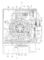
検体分析装置1は、血液の凝固・線溶機能に関連する特定の物質の量や活性の度合いを光学的に測定して分析するための装置であり、検体として血漿を用いる。検体分析装置1は、図1〜図5に示すように、測定機構部2と、測定機構部2の前面側に配置された搬送機構部3と、測定機構部2に電気的に接続された制御装置4とにより構成されている。   The sample analyzer 1 is a device for optically measuring and analyzing the amount and activity level of a specific substance related to blood coagulation / fibrinolysis function, and uses plasma as a sample. As shown in FIGS. 1 to 5, the sample analyzer 1 is electrically connected to the measurement mechanism unit 2, the transport mechanism unit 3 disposed on the front side of the measurement mechanism unit 2, and the measurement mechanism unit 2. It is comprised by the control apparatus 4.

搬送機構部3は、測定機構部2に検体を供給するために、検体を収容した複数(本実施形態では、10本)の試験管250が載置されたラック251を測定機構部2の吸引位置2a(図3参照)に搬送する機能を有している。   In order to supply the sample to the measurement mechanism unit 2, the transport mechanism unit 3 sucks the rack 251 on which a plurality of (in this embodiment, ten) test tubes 250 containing the sample are placed by the measurement mechanism unit 2. It has a function of conveying to position 2a (see FIG. 3).

制御装置4は、パーソナルコンピュータ401(PC)などからなり、図1に示すように、制御部4aと、表示部4bと、キーボード4cとを含んでいる。制御部4aは、後述する測定機構部2の制御部501に、測定機構部2および搬送機構部3の動作開始の信号を伝えるとともに、測定機構部2で得られた検体の光学的な情報を分析するための機能を有している。この制御部4aは、CPU、ROM、RAMなどからなる。また、表示部4bは、制御部4aで得られた分析結果などを表示するために設けられている。   The control device 4 includes a personal computer 401 (PC) or the like, and includes a control unit 4a, a display unit 4b, and a keyboard 4c as shown in FIG. The control unit 4a transmits operation start signals of the measurement mechanism unit 2 and the transport mechanism unit 3 to the control unit 501 of the measurement mechanism unit 2 described later, and optical information of the specimen obtained by the measurement mechanism unit 2 It has a function to analyze. The control unit 4a includes a CPU, a ROM, a RAM, and the like. The display unit 4b is provided for displaying the analysis result obtained by the control unit 4a.

次に、制御装置4の構成について詳細に説明する。制御部4aは、図6に示すように、CPU401aと、ROM401bと、RAM401cと、ハードディスク401dと、読出装置401eと、入出力インタフェース401fと、通信インタフェース401gと、画像出力インタフェース401hとから主として構成されている。CPU401a、ROM401b、RAM401c、ハードディスク401d、読出装置401e、入出力インタフェース401f、通信インタフェース401g、および画像出力インタフェース401hは、バス401iによって接続されている。   Next, the configuration of the control device 4 will be described in detail. As shown in FIG. 6, the control unit 4a mainly includes a CPU 401a, a ROM 401b, a RAM 401c, a hard disk 401d, a reading device 401e, an input / output interface 401f, a communication interface 401g, and an image output interface 401h. ing. The CPU 401a, ROM 401b, RAM 401c, hard disk 401d, reading device 401e, input / output interface 401f, communication interface 401g, and image output interface 401h are connected by a bus 401i.

CPU401aは、ROM401bに記憶されているコンピュータプログラムおよびRAM401cにロードされたコンピュータプログラムを実行することが可能である。そして、後述するようなアプリケーションプログラム404aをCPU401aが実行することにより、コンピュータ401が制御装置4として機能する。   The CPU 401a can execute computer programs stored in the ROM 401b and computer programs loaded in the RAM 401c. The computer 401 functions as the control device 4 when the CPU 401a executes an application program 404a as will be described later.

ROM401bは、マスクROM、PROM、EPROM、EEPROMなどによって構成されており、CPU401aに実行されるコンピュータプログラムおよびこれに用いるデータなどが記録されている。   The ROM 401b is configured by a mask ROM, PROM, EPROM, EEPROM, or the like, in which computer programs executed by the CPU 401a and data used for the same are recorded.

RAM401cは、SRAMまたはDRAMなどによって構成されている。RAM401cは、ROM401bおよびハードディスク401dに記録されているコンピュータプログラムの読み出しに用いられる。また、これらのコンピュータプログラムを実行するときに、CPU401aの作業領域として利用される。   The RAM 401c is configured by SRAM, DRAM, or the like. The RAM 401c is used to read out computer programs recorded in the ROM 401b and the hard disk 401d. Further, when these computer programs are executed, they are used as a work area of the CPU 401a.

ハードディスク401dは、オペレーティングシステムおよびアプリケーションプログラムなど、CPU401aに実行させるための種々のコンピュータプログラムおよびそのコンピュータプログラムの実行に用いるデータがインストールされている。また、本実施形態では、後述する試薬マスタ、試薬ロットマスタおよび容器マスタなどのテーブルは、このハードディスク401dに記憶されている。   The hard disc 401d is installed with various computer programs to be executed by the CPU 401a, such as an operating system and application programs, and data used for executing the computer programs. In the present embodiment, tables such as a later-described reagent master, reagent lot master, and container master are stored in the hard disk 401d.

読出装置401eは、フレキシブルディスクドライブ、CD−ROMドライブ、またはDVD−ROMドライブなどによって構成されており、可搬型記録媒体404に記録されたコンピュータプログラムまたはデータを読み出すことができる。また、可搬型記録媒体404には、本実施形態に係るアプリケーションプログラム404aが格納されており、コンピュータ401がその可搬型記録媒体404からアプリケーションプログラム404aを読み出し、そのアプリケーションプログラム404aをハードディスク401dにインストールすることが可能である。   The reading device 401e is configured by a flexible disk drive, a CD-ROM drive, a DVD-ROM drive, or the like, and can read a computer program or data recorded on the portable recording medium 404. The portable recording medium 404 stores an application program 404a according to the present embodiment, and the computer 401 reads the application program 404a from the portable recording medium 404 and installs the application program 404a on the hard disk 401d. It is possible.

なお、上記アプリケーションプログラム404aは、可搬型記録媒体404によって提供されるのみならず、電気通信回線(有線、無線を問わない)によってコンピュータ401と通信可能に接続された外部の機器から上記電気通信回線を通じて提供することも可能である。たとえば、上記アプリケーションプログラム404aがインターネット上のサーバコンピュータのハードディスク内に格納されており、このサーバコンピュータにコンピュータ401がアクセスして、そのアプリケーションプログラム404aをダウンロードし、これをハードディスク401dにインストールすることも可能である。   Note that the application program 404a is not only provided by the portable recording medium 404, but also from an external device communicatively connected to the computer 401 by an electric communication line (whether wired or wireless). It is also possible to provide through. For example, the application program 404a is stored in a hard disk of a server computer on the Internet, and the computer 401 can access the server computer to download the application program 404a and install it on the hard disk 401d. It is.

また、ハードディスク401dには、たとえば、米マイクロソフト社が製造販売するWindows(登録商標)などのグラフィカルユーザインタフェース環境を提供するオペレーティングシステムがインストールされている。以下の説明においては、本実施形態に係るアプリケーションプログラム404aは上記オペレーティングシステム上で動作するものとしている。   In addition, an operating system that provides a graphical user interface environment such as Windows (registered trademark) manufactured and sold by US Microsoft Corporation is installed in the hard disc 401d. In the following description, it is assumed that the application program 404a according to the present embodiment operates on the operating system.

入出力インタフェース401fは、たとえば、USB、IEEE1394、RS−232Cなどのシリアルインタフェース、SCSI、IDE、IEEE1284などのパラレルインタフェース、およびD/A変換器、A/D変換器などからなるアナログインタフェースなどから構成されている。入出力インタフェース401fには、キーボード4cが接続されており、ユーザがそのキーボード4cを使用することにより、コンピュータ401にデータを入力することが可能である。   The input / output interface 401f includes, for example, a serial interface such as USB, IEEE 1394, and RS-232C, a parallel interface such as SCSI, IDE, and IEEE1284, and an analog interface including a D / A converter and an A / D converter. Has been. A keyboard 4c is connected to the input / output interface 401f, and the user can input data to the computer 401 by using the keyboard 4c.

通信インタフェース401gは、たとえば、Ethernet(登録商標)インタフェースである。コンピュータ401は、その通信インタフェース401gにより、所定の通信プロトコルを使用して測定機構部2との間でデータの送受信が可能である。   The communication interface 401g is, for example, an Ethernet (registered trademark) interface. The computer 401 can transmit and receive data to and from the measurement mechanism unit 2 using a predetermined communication protocol through the communication interface 401g.

画像出力インタフェース401hは、LCDまたはCRTなどで構成された表示部4bに接続されており、CPU401aから与えられた画像データに応じた映像信号を表示部4bに出力するようになっている。表示部4bは、入力された映像信号にしたがって、画像(画面)を表示する。   The image output interface 401h is connected to a display unit 4b configured by an LCD or a CRT, and outputs a video signal corresponding to image data given from the CPU 401a to the display unit 4b. The display unit 4b displays an image (screen) according to the input video signal.

ここで、本実施形態では、表示部4bは、図7に示すように、後述する試薬保存部6の試薬の配置を表示する試薬配置画面410を表示することが可能である。試薬配置画面410は、試薬配置表示領域420と、試薬情報表示領域430と、コマンド表示領域440とを有する。また、試薬配置画面410には、検体分析装置1の測定を開始するための測定開始ボタン411と、測定を停止するための測定停止ボタン412とが設けられている。なお、表示部4bは、タッチパネル機能を有し、試薬配置画面410に表示されるボタンなどをユーザが直接触れることによって選択または操作可能である。   Here, in the present embodiment, as shown in FIG. 7, the display unit 4b can display a reagent arrangement screen 410 that displays the arrangement of reagents in the reagent storage unit 6 described later. The reagent arrangement screen 410 has a reagent arrangement display area 420, a reagent information display area 430, and a command display area 440. Further, the reagent arrangement screen 410 is provided with a measurement start button 411 for starting the measurement of the sample analyzer 1 and a measurement stop button 412 for stopping the measurement. The display unit 4b has a touch panel function, and can be selected or operated by a user directly touching a button or the like displayed on the reagent arrangement screen 410.

試薬配置表示領域420は、後述する第1試薬テーブル11に配置されている試薬が表示される複数の第1試薬表示領域421と、後述する第2試薬テーブル12に配置されている試薬が表示される複数の第2試薬表示領域422とを含む。第1試薬表示領域421は、試薬の位置を表示する位置表示部421aと、試薬名を表示する試薬名表示部421bと、試薬の残量を表示する残量表示部421cとを含む。また、第2試薬表示領域422は、試薬の位置を表示する位置表示部422aと、試薬名を表示する試薬名表示部422bと、試薬の残量を表示する残量表示部422cとを含む。試薬名表示部421aおよび422aに表示される試薬の位置は、後述する第1試薬容器ラック310のバーコード311b、312b(図8参照)、第2試薬容器ラック320のバーコード321b〜326b(図9参照)および第3試薬容器ラック330のバーコード331b〜338b(図13参照)を試薬バーコードリーダ350により読み取ることによって表示される。また、試薬名表示部421bおよび422bに表示される試薬名は、試薬容器300のバーコード300aを試薬バーコードリーダ350により読み取った値を元に、別途用意された一覧表を参照して表示される。また、残量表示部421cおよび422cに表示される試薬の残量は、試薬が収容される容器の種類およびその試薬が吸引された回数などから算出した値を元に表示される。   The reagent arrangement display area 420 displays a plurality of first reagent display areas 421 in which reagents arranged in the first reagent table 11 described later are displayed, and reagents arranged in the second reagent table 12 described later. And a plurality of second reagent display areas 422. The first reagent display area 421 includes a position display unit 421a that displays the position of the reagent, a reagent name display unit 421b that displays the reagent name, and a remaining amount display unit 421c that displays the remaining amount of the reagent. The second reagent display area 422 includes a position display unit 422a that displays the position of the reagent, a reagent name display unit 422b that displays the reagent name, and a remaining amount display unit 422c that displays the remaining amount of the reagent. The positions of the reagents displayed in the reagent name display units 421a and 422a are the barcodes 311b and 312b (see FIG. 8) of the first reagent container rack 310, which will be described later, and the barcodes 321b to 326b of the second reagent container rack 320 (see FIG. 9) and the barcodes 331b to 338b (see FIG. 13) of the third reagent container rack 330 are read by the reagent barcode reader 350. The reagent names displayed in the reagent name display units 421b and 422b are displayed with reference to a list prepared separately based on the value obtained by reading the barcode 300a of the reagent container 300 with the reagent barcode reader 350. The In addition, the remaining amount of the reagent displayed in the remaining amount display units 421c and 422c is displayed based on a value calculated from the type of container in which the reagent is stored, the number of times the reagent has been aspirated, and the like.

また、第1試薬表示領域421は、第1試薬テーブル11に配置される2つの試薬容器300を保持可能な5つの第1試薬容器ラック310に対応する領域毎に2つずつ分割されて表示される。また、第2試薬表示領域422は、第2試薬テーブル12に配置される6つの試薬容器300を保持可能な5つの第2試薬容器ラック320に対応する領域毎に6つずつ分割されて表示される。なお、図7には、第2試薬テーブル12に第2試薬容器ラック320が配置された場合しか示されていないが、第2試薬テーブル12に8つの試薬容器300を保持可能な第3試薬容器ラック330が配置された場合には、第2試薬表示領域422は、第3試薬容器ラック330に対応する領域毎に8つずつ分割されて表示される。これにより、試薬配置画面410では、どの試薬テーブル(第1試薬テーブル11または第2試薬テーブル12)の、どの試薬容器ラック(第1試薬容器ラック310、第2試薬容器ラック320または第3試薬容器ラック330)の、どの位置に試薬が配置されているかを確認することが可能である。   In addition, the first reagent display area 421 is displayed by being divided into two for each of the areas corresponding to the five first reagent container racks 310 that can hold the two reagent containers 300 arranged in the first reagent table 11. The In addition, the second reagent display area 422 is divided and displayed for each of the areas corresponding to the five second reagent container racks 320 that can hold the six reagent containers 300 arranged in the second reagent table 12. The FIG. 7 shows only the case where the second reagent container rack 320 is arranged on the second reagent table 12, but the third reagent container capable of holding eight reagent containers 300 on the second reagent table 12 is shown. When the rack 330 is arranged, the second reagent display area 422 is displayed by being divided into eight for each area corresponding to the third reagent container rack 330. As a result, on the reagent arrangement screen 410, which reagent table (first reagent table 11 or second reagent table 12), which reagent container rack (first reagent container rack 310, second reagent container rack 320 or third reagent container). It is possible to confirm in which position of the rack 330) the reagent is arranged.

また、第1試薬容器ラック310(図8)、第2試薬容器ラック320(図9)または第3試薬容器ラック330(図13)が第1試薬テーブル11または第2試薬テーブル12に配置されていない場合には、第1試薬表示領域421または第2試薬表示領域422には、何も表示されない。また、第1試薬容器ラック310、第2試薬容器ラック320または第3試薬容器ラック330が第1試薬テーブル11または第2試薬テーブル12に配置されており、試薬容器ラックに保持される試薬容器300がない場合には、第1試薬表示領域421または第2試薬表示領域422には、位置表示部421aまたは位置表示部422aのみに表示がなされる。この点については、後に詳細に説明する。   Further, the first reagent container rack 310 (FIG. 8), the second reagent container rack 320 (FIG. 9) or the third reagent container rack 330 (FIG. 13) is arranged on the first reagent table 11 or the second reagent table 12. If not, nothing is displayed in the first reagent display area 421 or the second reagent display area 422. Further, the first reagent container rack 310, the second reagent container rack 320, or the third reagent container rack 330 is disposed on the first reagent table 11 or the second reagent table 12, and the reagent container 300 held in the reagent container rack. If there is no, the first reagent display area 421 or the second reagent display area 422 is displayed only on the position display section 421a or the position display section 422a. This point will be described in detail later.

また、試薬情報表示領域430には、第1試薬表示領域421または第2試薬表示領域422において指定された試薬の属性情報(試薬名、使用順、使用可能な残量(使用可能量)、残りテスト数、攪拌の有無、ロット番号、試薬容器の種類、試薬の有効期限、セット日、セット時刻など)およびホルダ番号が表示される。この試薬の属性情報によって、ユーザは、試薬の交換時期を判断することが可能である。   In the reagent information display area 430, the attribute information of the reagent specified in the first reagent display area 421 or the second reagent display area 422 (reagent name, use order, usable remaining amount (usable amount), remaining amount) The number of tests, presence / absence of agitation, lot number, reagent container type, reagent expiration date, set date, set time, etc.) and holder number are displayed. Based on the reagent attribute information, the user can determine the replacement time of the reagent.

また、コマンド表示領域440には、試薬の交換または追加を指示するための交換・追加指示ボタン440aと、試薬情報の編集を行うための編集ボタン440bと、試薬ロットをマニュアルで入力するための試薬ロット設定ボタン440cとを含む。本実施形態では、試薬が指定された状態で、交換・追加指示ボタン440aが選択されることによって、指定された試薬が収容された試薬容器300を保持する第1試薬容器ラック310、第2試薬容器ラック320または第3試薬容器ラック330が、検体分析装置1から取り出し可能な取出位置に移動されるように構成されている。なお、試薬の追加が行われる場合には、試薬が配置されていない第1試薬表示領域421または第2試薬表示領域422が指定された状態で、交換・追加指示ボタン440aが選択される。これにより、試薬が収容されていない第1試薬容器ラック310、第2試薬容器ラック320または第3試薬容器ラック330が取出位置に移動される。   In the command display area 440, a replacement / addition instruction button 440a for instructing replacement or addition of a reagent, an editing button 440b for editing reagent information, and a reagent for manually inputting a reagent lot A lot setting button 440c. In the present embodiment, when the replacement / addition instruction button 440a is selected in a state in which the reagent is specified, the first reagent container rack 310 and the second reagent that hold the reagent container 300 in which the specified reagent is stored. The container rack 320 or the third reagent container rack 330 is configured to be moved to an extraction position where it can be extracted from the sample analyzer 1. When a reagent is added, the replacement / addition instruction button 440a is selected in a state where the first reagent display area 421 or the second reagent display area 422 where no reagent is arranged is specified. Accordingly, the first reagent container rack 310, the second reagent container rack 320, or the third reagent container rack 330 that does not contain the reagent is moved to the take-out position.

搬送機構部3は、図1〜図3に示すように、測定機構部2に検体を供給するために、検体を収容した複数(本実施形態では、10本)の試験管250が載置されたラック251を測定機構部2の吸引位置2a(図3参照)に搬送する機能を有している。また、搬送機構部3は、未処理の検体を収容した試験管250が収納されたラック251をセットするためのラックセット領域3aと、処理済みの検体を収容した試験管250が収納されたラック251を収容するためのラック収容領域3bとを有している。   As shown in FIGS. 1 to 3, the transport mechanism unit 3 is provided with a plurality of (in this embodiment, ten) test tubes 250 that contain samples in order to supply the sample to the measurement mechanism unit 2. The rack 251 is transported to the suction position 2a (see FIG. 3) of the measurement mechanism unit 2. In addition, the transport mechanism unit 3 includes a rack set region 3a for setting a rack 251 in which a test tube 250 that stores an unprocessed sample is stored, and a rack in which a test tube 250 that stores a processed sample is stored. And a rack accommodating area 3b for accommodating 251.

測定機構部2は、搬送機構部3から供給された検体に対して光学的な測定を行うことにより、供給された検体に関する光学的な情報を取得することが可能なように構成されている。本実施形態では、搬送機構部3のラック251に載置された試験管250から測定機構部2のキュベット200内に分注された検体に対して光学的な測定が行われる。また、測定機構部2は、図3に示すように、試薬を保存するための試薬保存部6と、試薬を交換または追加するための試薬交換部7とを含んでいる。   The measurement mechanism unit 2 is configured to be able to acquire optical information regarding the supplied sample by performing optical measurement on the sample supplied from the transport mechanism unit 3. In the present embodiment, optical measurement is performed on the sample dispensed from the test tube 250 placed on the rack 251 of the transport mechanism unit 3 into the cuvette 200 of the measurement mechanism unit 2. Further, as shown in FIG. 3, the measurement mechanism unit 2 includes a reagent storage unit 6 for storing the reagent and a reagent replacement unit 7 for replacing or adding the reagent.

測定機構部2は、図14に示すように、検体分注駆動部70aと、試薬分注駆動部120aと、第1駆動部502と、第2駆動部503と、第1ロック検知部504と、第2ロック検知部505と、試薬バーコードリーダ350と、検体バーコードリーダ3cと、光学的情報取得部130と、搬送機構部3などに電気的に接続される制御部501とを有している。   As shown in FIG. 14, the measurement mechanism unit 2 includes a sample dispensing drive unit 70a, a reagent dispensing drive unit 120a, a first drive unit 502, a second drive unit 503, and a first lock detection unit 504. A second lock detection unit 505, a reagent barcode reader 350, a sample barcode reader 3c, an optical information acquisition unit 130, and a control unit 501 electrically connected to the transport mechanism unit 3 and the like. ing.

検体分注駆動部70aは、後述する検体分注アーム70(図3および図5参照)を回転上下させる機能を有するステッピングモータ部70bと、ステッピングモータ部70bを駆動させるための駆動回路(図示せず)と、検体を吸引および分注するためのポンプ(図示せず)とを備えている。   The sample dispensing drive unit 70a includes a stepping motor unit 70b having a function of rotating and moving a sample dispensing arm 70 (see FIGS. 3 and 5), which will be described later, and a drive circuit (not shown) for driving the stepping motor unit 70b. And a pump (not shown) for aspirating and dispensing the sample.

試薬分注駆動部120aは、後述する試薬分注アーム120(図3および図5参照)を回転上下させる機能を有するステッピングモータ部120bと、ステッピングモータ部120bを駆動させるための駆動回路(図示せず)と、試薬を吸引および分注するためのポンプ(図示せず)とを備えている。   The reagent dispensing drive unit 120a includes a stepping motor unit 120b having a function of rotating and moving a reagent dispensing arm 120 (see FIGS. 3 and 5), which will be described later, and a drive circuit (not shown) for driving the stepping motor unit 120b. And a pump (not shown) for aspirating and dispensing the reagent.

第1駆動部502は、後述する第1試薬テーブル11(図5参照)を回転させる機能を有する第1ステッピングモータ(図示せず)と、第1ステッピングモータを駆動させるための駆動回路(図示せず)とを備えている。そして、第1試薬テーブル11は、制御部501から第1駆動部502に供給された駆動パルス信号のパルス数に応じた分だけ回転し、停止する。   The first drive unit 502 includes a first stepping motor (not shown) having a function of rotating a first reagent table 11 (see FIG. 5) described later, and a drive circuit (not shown) for driving the first stepping motor. )). Then, the first reagent table 11 rotates by an amount corresponding to the number of pulses of the drive pulse signal supplied from the control unit 501 to the first drive unit 502 and stops.

同様に、第2駆動部503は、後述する第2試薬テーブル12(図5参照)を回転させる機能を有する第2ステッピングモータ(図示せず)と、第2ステッピングモータを駆動させるための駆動回路(図示せず)とを備えている。そして、第2試薬テーブル12は、制御部501から第2駆動部503に供給された駆動パルス信号のパルス数に応じた分だけ回転し、停止する。   Similarly, the second drive unit 503 includes a second stepping motor (not shown) having a function of rotating a second reagent table 12 (see FIG. 5) described later, and a drive circuit for driving the second stepping motor. (Not shown). Then, the second reagent table 12 rotates by an amount corresponding to the number of pulses of the drive pulse signal supplied from the control unit 501 to the second drive unit 503 and stops.

なお、制御部501は、供給した駆動パルス信号のパルス数をカウントすることにより、第1試薬テーブル11および第2試薬テーブル12の原点位置からの各試薬テーブル11、12の回転移動量を決定し、各試薬テーブル11、12の回転移動を制御することが可能である。   The control unit 501 counts the number of pulses of the supplied drive pulse signal to determine the rotational movement amount of each reagent table 11, 12 from the origin position of the first reagent table 11 and the second reagent table 12. The rotational movement of the reagent tables 11 and 12 can be controlled.

第1ロック検知部504は、後述する第1蓋部30(図3参照)のロック状態を検知するとともに、ロックされたときにロック信号を制御部501に送信する機能を有している。   The first lock detection unit 504 has a function of detecting a lock state of a first lid 30 (see FIG. 3) described later and transmitting a lock signal to the control unit 501 when locked.

同様に、第2ロック検知部505は、後述する第2蓋部40(図3参照)のロック状態を検知するとともに、ロックされたときにロック信号を制御部501に送信する機能を有している。   Similarly, the second lock detection unit 505 has a function of detecting a lock state of a second lid unit 40 (see FIG. 3) described later and transmitting a lock signal to the control unit 501 when locked. Yes.

試薬バーコードリーダ350は、第1試薬テーブル11および第2試薬テーブル12上の各バーコードを読み取る機能を有しており、後述する試薬保存部6の側面21の近傍に、試薬保存部6と所定の距離を隔てて設けられている(図3〜図5参照)。この試薬バーコードリーダ350は、制御部501との間でデータの送受信を行うことが可能であるとともに、試薬バーコードリーダ350をON/OFF制御するための駆動回路(図示せず)を有している。なお、試薬バーコードリーダ350の位置は常に固定されている。   The reagent barcode reader 350 has a function of reading the barcodes on the first reagent table 11 and the second reagent table 12, and in the vicinity of the side surface 21 of the reagent storage unit 6 described later, They are provided at a predetermined distance (see FIGS. 3 to 5). The reagent barcode reader 350 can transmit / receive data to / from the control unit 501, and has a drive circuit (not shown) for ON / OFF control of the reagent barcode reader 350. ing. Note that the position of the reagent barcode reader 350 is always fixed.

検体バーコードリーダ3cは、搬送機構部3によって搬送されたラック251に載置された検体を収容した試験管250に貼付されたバーコードを読み取る機能を有しており、前述した測定機構部2の吸引位置2aの近傍に、搬送機構部3によって搬送されるラック251に対向するように設けられている(図3〜図5参照)。この検体バーコードリーダ3cは、制御部501との間でデータの送受信を行うことが可能であるとともに、検体バーコードリーダ3cをON/OFF制御するための駆動回路(図示せず)を有している。なお、検体バーコードリーダ3cの位置は常に固定されている。   The sample barcode reader 3c has a function of reading a barcode attached to the test tube 250 containing the sample placed on the rack 251 conveyed by the conveyance mechanism unit 3, and the measurement mechanism unit 2 described above. Is provided in the vicinity of the suction position 2a so as to face the rack 251 transported by the transport mechanism unit 3 (see FIGS. 3 to 5). The sample barcode reader 3c can transmit / receive data to / from the control unit 501, and has a drive circuit (not shown) for ON / OFF control of the sample barcode reader 3c. ing. The position of the specimen barcode reader 3c is always fixed.

光学情報取得部130(図3および図5参照)は、検体の光学的情報を取得するための機能を有しており、制御部501との間でデータの送受信を行うことが可能なように構成されている。光学情報取得部130の詳細については後述する。   The optical information acquisition unit 130 (see FIGS. 3 and 5) has a function for acquiring the optical information of the specimen so that data can be transmitted to and received from the control unit 501. It is configured. Details of the optical information acquisition unit 130 will be described later.

制御部501は、図15に示すように、CPU501aとROM501bと、RAM501cと、通信インタフェース501dとから主として構成されている。   As shown in FIG. 15, the control unit 501 mainly includes a CPU 501a, a ROM 501b, a RAM 501c, and a communication interface 501d.

CPU501aは、ROM501bに記憶されているコンピュータプログラムおよびRAM501cに読み出されたコンピュータプログラムを実行することが可能である。ROM501bは、CPU501aに実行させるためのコンピュータプログラム及び当該コンピュータプログラムの実行に用いるデータ等を記憶している。RAM501cは、ROM501bに記憶しているコンピュータプログラムの読み出しに用いられる。また、これらのコンピュータプログラムを実行するときに、CPU501aの作業領域として利用される。   The CPU 501a can execute a computer program stored in the ROM 501b and a computer program read into the RAM 501c. The ROM 501b stores a computer program to be executed by the CPU 501a, data used for executing the computer program, and the like. The RAM 501c is used for reading a computer program stored in the ROM 501b. Further, when these computer programs are executed, they are used as a work area of the CPU 501a.

通信インタフェース501dは、制御装置4に接続されており、検体の光学的な情報を制御装置4に送信するとともに、制御装置4の制御部4aからの信号を受信するための機能を果たす。また、通信インタフェース501dは、搬送機構部3および測定機構部2の各部を駆動するためのCPU501aからの指令を送信するための機能を有する。   The communication interface 501d is connected to the control device 4 and transmits optical information of the specimen to the control device 4 and functions to receive a signal from the control unit 4a of the control device 4. The communication interface 501d has a function for transmitting a command from the CPU 501a for driving each part of the transport mechanism unit 3 and the measurement mechanism unit 2.

また、測定機構部2は、図3に示すように、試薬を保存するための試薬保存部6と、試薬を交換または追加するための試薬交換部7とを含んでいる。   Further, as shown in FIG. 3, the measurement mechanism unit 2 includes a reagent storage unit 6 for storing the reagent and a reagent replacement unit 7 for replacing or adding the reagent.

試薬保存部6は、キュベット200内の検体に添加される試薬を収容した試薬容器300を、低温(約10℃)で冷蔵保存するとともに、回転方向に搬送するために設けられている。試薬を低温で保存することにより、試薬が変質することが抑制される。また、試薬保存部6は、図3〜図5に示すように、試薬の保持および回転搬送を行う試薬搬送部10(図4および図5参照)と、試薬搬送部10の周囲および上方を覆うように設けられた外壁部20(図3参照)とを含んでいる。また、試薬が保持される試薬搬送部10は、外壁部20と、後述する試薬交換部7の第1蓋部30および第2蓋部40とにより形成される冷蔵領域に配置される。   The reagent storage unit 6 is provided to refrigerate and store the reagent container 300 containing the reagent added to the specimen in the cuvette 200 at a low temperature (about 10 ° C.) and to transport it in the rotation direction. By storing the reagent at a low temperature, the reagent is prevented from being altered. As shown in FIGS. 3 to 5, the reagent storage unit 6 covers the reagent transport unit 10 (see FIGS. 4 and 5) that holds and rotates and transports the reagent, and the reagent transport unit 10. The outer wall part 20 (refer FIG. 3) provided in this way is included. In addition, the reagent transport unit 10 that holds the reagent is disposed in a refrigerated region formed by the outer wall 20 and a first lid 30 and a second lid 40 of the reagent replacement unit 7 described later.

この試薬搬送部10は、図5に示すように、円形状の第1試薬テーブル11と、円形状の第1試薬テーブル11の外側に、第1試薬テーブル11に対して同心円状に配置された円環形状の第2試薬テーブル12とを含む。また、第1試薬テーブル11は、試薬容器300を保持する第1試薬容器ラック310が着脱可能に配置されるように構成されており、第2試薬テーブル12は、試薬容器300を保持する第2試薬容器ラック320および第3試薬容器ラック330が着脱可能に配置されるように構成されている。また、外壁部20は、側面21(図4参照)と、側面21に固定されている上面22(図3参照)と、取り外し可能な蓋部23(図3参照)とにより構成されている。また、試薬保存部6の側面21(図4参照)の近傍には、試薬保存部6と所定の距離を隔てて試薬バーコードリーダ350が設けられている。   As shown in FIG. 5, the reagent transport unit 10 is arranged concentrically with the first reagent table 11 on the outer side of the circular first reagent table 11 and the circular first reagent table 11. And an annular second reagent table 12. The first reagent table 11 is configured such that the first reagent container rack 310 that holds the reagent container 300 is detachably disposed. The second reagent table 12 is a second reagent table that holds the reagent container 300. The reagent container rack 320 and the third reagent container rack 330 are configured to be detachable. Moreover, the outer wall part 20 is comprised by the side surface 21 (refer FIG. 4), the upper surface 22 (refer FIG. 3) fixed to the side surface 21, and the removable cover part 23 (refer FIG. 3). Further, a reagent barcode reader 350 is provided in the vicinity of the side surface 21 (see FIG. 4) of the reagent storage unit 6 with a predetermined distance from the reagent storage unit 6.

第1試薬テーブル11および第2試薬テーブル12は、それぞれ、時計回り方向および反時計回り方向の両方に回転可能で、かつ、各々のテーブルが互いに独立して回転可能なように構成されている。これにより、試薬が収容された試薬容器300を保持する第1試薬容器ラック310、第2試薬容器ラック320および第3試薬容器ラック330は、それぞれ、第1試薬テーブル11および第2試薬テーブル12によって回転方向に搬送される。また、試薬容器300を回転方向に搬送することによって、後述する試薬分注アーム120が試薬を分注する際に、分注対象の試薬を試薬分注アーム120の近傍に配置させることが可能である。   The first reagent table 11 and the second reagent table 12 are configured to be able to rotate both in the clockwise direction and in the counterclockwise direction, and to be able to rotate independently of each other. As a result, the first reagent container rack 310, the second reagent container rack 320, and the third reagent container rack 330 that hold the reagent containers 300 in which the reagents are stored are respectively separated by the first reagent table 11 and the second reagent table 12. It is conveyed in the direction of rotation. Further, by transporting the reagent container 300 in the rotation direction, it is possible to arrange the reagent to be dispensed in the vicinity of the reagent dispensing arm 120 when the reagent dispensing arm 120 described later dispenses the reagent. is there.

また、外壁部20の側面21には、断熱材(図示せず)が取り付けられており、試薬保存部6(冷蔵領域)内の冷気を逃がさないように構成されている。また、図4に示すように、外壁部20の側面21の試薬バーコードリーダ350と対向する位置には、開閉可能なシャッタ21aが設けられている。このシャッタ21aは、試薬バーコードリーダ350によって試薬容器300、第1試薬容器ラック310、第2試薬容器ラック320および第3試薬容器ラック330のバーコードを読み取る時にのみ開くように構成されている。これにより、試薬保存部6(冷蔵領域)内の冷気が外部に逃げることが抑制される。   Further, a heat insulating material (not shown) is attached to the side surface 21 of the outer wall portion 20 so that the cold air in the reagent storage portion 6 (refrigerated region) is not released. As shown in FIG. 4, an openable / closable shutter 21 a is provided at a position facing the reagent barcode reader 350 on the side surface 21 of the outer wall portion 20. The shutter 21a is configured to be opened only when the barcodes of the reagent container 300, the first reagent container rack 310, the second reagent container rack 320, and the third reagent container rack 330 are read by the reagent barcode reader 350. Thereby, it is suppressed that the cold in the reagent storage part 6 (refrigeration area | region) escapes outside.

また、図3に示すように、外壁部20の上面22は、4つの穴部22a、22b、22cおよび22dを含む。この4つの穴部22a、22b、22cおよび22dを介して、試薬分注アーム120により試薬保存部6に保存されている試薬の吸引が行われる。なお、穴部22a〜22cは、第2試薬容器ラック320および第3試薬容器ラック330に保持されている試薬容器300の上方に位置する。この穴部22a〜22cを介して、第2試薬容器ラック320および第3試薬容器ラック330に保持されている試薬容器300から試薬の吸引が行われる。また、穴部22dは、第1試薬容器ラック310に保持されている試薬容器300の上方に位置する。この穴部22dを介して、第1試薬容器ラック310に保持されている試薬容器300から試薬の吸引が行われる。   Moreover, as shown in FIG. 3, the upper surface 22 of the outer wall part 20 includes four holes 22a, 22b, 22c and 22d. The reagent stored in the reagent storage unit 6 is aspirated by the reagent dispensing arm 120 through the four holes 22a, 22b, 22c and 22d. The holes 22 a to 22 c are located above the reagent containers 300 held in the second reagent container rack 320 and the third reagent container rack 330. The reagent is aspirated from the reagent containers 300 held in the second reagent container rack 320 and the third reagent container rack 330 through the holes 22a to 22c. Further, the hole 22d is located above the reagent container 300 held in the first reagent container rack 310. The reagent is aspirated from the reagent container 300 held in the first reagent container rack 310 through the hole 22d.

また、蓋部23が後述する第1蓋部30および第2蓋部40とともに取り外されることによって、試薬保存部6(冷蔵領域)に半円形状の開口が形成される。この開口を介して、検体分析装置1において測定を開始する際に、試薬保存部6に第1試薬容器ラック310、第2試薬容器ラック320、および第3試薬容器ラック330が配置される。   Further, when the lid portion 23 is removed together with the first lid portion 30 and the second lid portion 40 which will be described later, a semicircular opening is formed in the reagent storage portion 6 (refrigerated region). The first reagent container rack 310, the second reagent container rack 320, and the third reagent container rack 330 are arranged in the reagent storage unit 6 when the measurement is started in the sample analyzer 1 through this opening.

また、図5に示すように、第1試薬容器ラック310は、第1試薬テーブル11に5つ配置可能である。この5つの第1試薬容器ラック310に、試薬容器300が円環状に配置される。第1試薬容器ラック310は、図8および図10に示すように、試薬容器300を保持するための2つの保持部311および312と、保持部311および312の前面側にそれぞれ設けられた切欠部311aおよび312aと、上方に突出するように設けられた1つの把持部313とを含む。また、図8に示すように、保持部311および312は、平面的に見て円形状に形成されており、円筒形状の試薬容器300が差し込まれることにより試薬容器300を保持可能である。また、アダプタ(図示せず)を保持部311または312に取り付けることにより、上記保持部311または312の内径よりも小さい外径を有する試薬容器300を保持部311または312に保持させることが可能である。また、保持部311および312の外側面の前面側には、それぞれ、バーコード311bおよび312bが設けられており、保持部311および312の内側面には、それぞれ、バーコード311cおよび312cが設けられている。   Further, as shown in FIG. 5, five first reagent container racks 310 can be arranged on the first reagent table 11. The reagent containers 300 are annularly arranged in the five first reagent container racks 310. As shown in FIGS. 8 and 10, the first reagent container rack 310 includes two holding parts 311 and 312 for holding the reagent container 300, and a notch provided on the front side of the holding parts 311 and 312. 311a and 312a and one grip part 313 provided so as to protrude upward. As shown in FIG. 8, the holding portions 311 and 312 are formed in a circular shape when seen in a plan view, and can hold the reagent container 300 when the cylindrical reagent container 300 is inserted. Further, by attaching an adapter (not shown) to the holding unit 311 or 312, the reagent container 300 having an outer diameter smaller than the inner diameter of the holding unit 311 or 312 can be held by the holding unit 311 or 312. is there. Further, barcodes 311b and 312b are provided on the front side of the outer surface of the holding portions 311 and 312 respectively, and barcodes 311c and 312c are provided on the inner side surfaces of the holding portions 311 and 312 respectively. ing.

2つの保持部311および312は、検体から測定用試料を調製する際に添加される種々の試薬を収容した複数の試薬容器300を1つずつ保持することが可能である。すなわち、第1試薬テーブル11には、最大10個(2×5=10)の試薬容器300が配置可能である。また、切欠部311aおよび312aは、それぞれ、バーコード311cおよび312cを試薬バーコードリーダ350(図5参照)によって読み取るために設けられている。また、把持部313は、第1試薬容器ラック310を試薬保存部6から取り出す時に把持される。   The two holding units 311 and 312 can hold a plurality of reagent containers 300 each containing various reagents added when preparing a measurement sample from a specimen. That is, a maximum of ten (2 × 5 = 10) reagent containers 300 can be arranged in the first reagent table 11. The notches 311a and 312a are provided to read the barcodes 311c and 312c with the reagent barcode reader 350 (see FIG. 5), respectively. In addition, the grip portion 313 is gripped when the first reagent container rack 310 is taken out from the reagent storage portion 6.

バーコード311bおよび312bには、それぞれ、保持部311および312の位置を識別するためのホルダ番号情報が含まれている。また、バーコード311cおよび312cには、保持部311および312に保持される試薬容器300は存在しないことを示す情報(試薬容器無し情報)が含まれている。また、試薬容器300のバーコード300aには、試薬容器300に収容されている試薬の詳細情報(試薬名、試薬容器の種類、ロット番号、試薬の有効期限などの情報)を特定するための情報が含まれている。   The barcodes 311b and 312b include holder number information for identifying the positions of the holding units 311 and 312 respectively. The barcodes 311c and 312c include information (reagent absence information) indicating that the reagent container 300 held in the holding units 311 and 312 does not exist. In addition, the barcode 300a of the reagent container 300 includes information for specifying detailed information (information such as reagent name, reagent container type, lot number, and reagent expiration date) stored in the reagent container 300. It is included.

なお、たとえば、試薬容器300が保持部311に保持されている場合には、バーコード311cは読み取られず、試薬容器300のバーコード300aが読み取られる。すなわち、試薬バーコードリーダ350によってバーコード311bを読み取った後にバーコード300aを読み取った場合は、制御部4aは、バーコード300aによる試薬情報を有する試薬が保持部311に保持されていると認識するように構成されている。そして、試薬管理画面410の試薬配置表示領域420において、保持部311に対応する位置に第1試薬マーク421が表示されるように構成されている。また、試薬バーコードリーダ350によってバーコード311bを読み取った後にバーコード311cを読み取った場合は、制御部4aは、保持部311に保持されている試薬容器300は存在しないと認識するように構成されている。そして、試薬管理画面410の試薬配置表示領域420において、保持部311に対応する位置に試薬未配置マーク427が表示されるように構成されている。また、試薬バーコードリーダ350によってバーコード311bを読み取った後にバーコード300aまたはバーコード311cのいずれも読み取らなかった場合(試薬容器300が横を向いている場合など)には、制御部4aは、読み取りエラーを認識するとともに、表示部4bにおいて、読み取りが失敗したことを表すバーコード読取エラーマークEが表示されるように構成されている。また、第1試薬テーブル11に第1試薬容器ラック自体が配置されていない場合には、試薬バーコードリーダ350は、第1試薬容器ラック310のバーコード311b、312b、311c、312cおよび試薬容器300のバーコード300aを読み取ることがないように構成されている。このため、試薬管理画面410の試薬配置表示領域420において、第1試薬容器ラック310が配置されていない部分に対応する第1ラックマーク424上には、ラック未配置マーク426が表示されるように構成されている。   For example, when the reagent container 300 is held by the holding unit 311, the barcode 311 c is not read, and the barcode 300 a of the reagent container 300 is read. That is, when the barcode 300a is read after the barcode 311b is read by the reagent barcode reader 350, the control unit 4a recognizes that the reagent having the reagent information by the barcode 300a is held in the holding unit 311. It is configured as follows. In the reagent arrangement display area 420 of the reagent management screen 410, the first reagent mark 421 is displayed at a position corresponding to the holding unit 311. When the barcode 311c is read after the barcode 311b is read by the reagent barcode reader 350, the control unit 4a is configured to recognize that the reagent container 300 held in the holding unit 311 does not exist. ing. In the reagent arrangement display area 420 of the reagent management screen 410, a reagent non-arrangement mark 427 is displayed at a position corresponding to the holding unit 311. When neither the barcode 300a nor the barcode 311c is read after the barcode 311b is read by the reagent barcode reader 350 (for example, when the reagent container 300 faces sideways), the control unit 4a In addition to recognizing a reading error, a bar code reading error mark E indicating that reading has failed is displayed on the display unit 4b. Further, when the first reagent container rack itself is not arranged on the first reagent table 11, the reagent barcode reader 350 displays the barcodes 311 b, 312 b, 311 c, 312 c of the first reagent container rack 310 and the reagent container 300. The barcode 300a is not read. Therefore, in the reagent arrangement display area 420 of the reagent management screen 410, the rack non-placement mark 426 is displayed on the first rack mark 424 corresponding to the portion where the first reagent container rack 310 is not placed. It is configured.

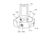
また、第2試薬容器ラック320は、図5に示すように、第2試薬テーブル12に5つ配置可能である。なお、第2試薬テーブル12には第2試薬容器ラック320以外に第3試薬容器ラック330(図13)も配置される。第2試薬容器ラック320の外形形状と第3試薬容器ラック330の外形形状は同じであるため、図示しないが、第3試薬容器ラック330も、第2試薬テーブル12に5つ配置可能である。この試薬容器ラック320および330に、試薬容器300が円環状に配置される。また、互いに隣接する第2試薬容器ラック320または第3試薬容器ラック330の5箇所の隙間のうち、1個所は、他の4箇所の隙間の間隔よりも大きい間隔を有する。この大きい間隔を有する隙間12aを介して、試薬保存部6の外部に位置する試薬バーコードリーダ350により、第2試薬テーブル12の内側に位置する第1試薬テーブル11に配置される第1試薬容器ラック310のバーコード311bおよび312bと、第1試薬容器ラック310に保持される試薬容器300のバーコード300aとが読み取られる。また、第2試薬容器ラック320は、図9、図11および図12に示すように、試薬容器300を保持するための6つの保持部321〜326と、保持部321〜326の前面側にそれぞれ設けられた切欠部321a〜326aと、上方に突出するように設けられた1つの把持部327とを含む。また、第2試薬容器ラック320の保持部321〜326は、第1試薬容器ラック310と同様に、平面的に見て円形状に形成されており、円筒形状の試薬容器300が差し込まれることにより試薬容器300を保持可能である。第2試薬容器ラック320には、第1試薬容器ラック310に配置された試薬と同じ試薬を配置することが可能に構成されている。   Further, five second reagent container racks 320 can be arranged on the second reagent table 12 as shown in FIG. In addition to the second reagent container rack 320, a third reagent container rack 330 (FIG. 13) is also arranged on the second reagent table 12. Although the outer shape of the second reagent container rack 320 and the outer shape of the third reagent container rack 330 are the same, five third reagent container racks 330 can be arranged on the second reagent table 12 although not shown. The reagent containers 300 are annularly arranged in the reagent container racks 320 and 330. In addition, one of the five gaps of the second reagent container rack 320 or the third reagent container rack 330 adjacent to each other has a gap larger than the gap of the other four gaps. The first reagent container disposed on the first reagent table 11 located inside the second reagent table 12 by the reagent barcode reader 350 located outside the reagent storage unit 6 through the gap 12a having a large interval. The barcodes 311b and 312b of the rack 310 and the barcode 300a of the reagent container 300 held in the first reagent container rack 310 are read. Further, as shown in FIGS. 9, 11, and 12, the second reagent container rack 320 has six holding portions 321 to 326 for holding the reagent container 300 and front sides of the holding portions 321 to 326, respectively. It includes notches 321a to 326a provided and one grip 327 provided so as to protrude upward. Further, the holding portions 321 to 326 of the second reagent container rack 320 are formed in a circular shape when seen in a plan view, like the first reagent container rack 310, and the cylindrical reagent container 300 is inserted. The reagent container 300 can be held. The second reagent container rack 320 is configured such that the same reagent as the reagent disposed in the first reagent container rack 310 can be disposed.

また、第2試薬容器ラック320の前列側の切欠部321aの両側には、バーコード321bと322bとが設けられている。また、同様に、切欠部323aの両側および切欠部325aの両側には、それぞれ、バーコード323bおよび324b、および、バーコード325bおよび326bが設けられている。また、保持部321〜326の内側面には、それぞれ、バーコード321c〜326cが設けられている。   Further, barcodes 321b and 322b are provided on both sides of the notch 321a on the front row side of the second reagent container rack 320. Similarly, barcodes 323b and 324b and barcodes 325b and 326b are provided on both sides of the notch 323a and on both sides of the notch 325a, respectively. In addition, barcodes 321c to 326c are provided on the inner side surfaces of the holding portions 321 to 326, respectively.

このバーコード321b〜326bには、それぞれ、保持部321〜326の位置を識別するためのホルダ番号情報が含まれている。また、バーコード321cおよび326cには、保持部321〜326に保持される試薬容器300は存在しないことを示す情報(試薬容器無し情報)が含まれている。   The bar codes 321b to 326b include holder number information for identifying the positions of the holding units 321 to 326, respectively. Further, the barcodes 321c and 326c include information (reagent absence information) indicating that the reagent container 300 held in the holding units 321 to 326 does not exist.

また、第3試薬容器ラック330は、図13に示すように、試薬容器300を保持するための8つの保持部331〜338を含み、保持部331〜338の前面側にそれぞれ設けられた切欠部(図示せず)の両側には、バーコード331b〜338bが設けられている。そして、このバーコード331b〜338bにも、それぞれ、保持部331〜338の位置を識別するためのホルダ番号情報が含まれている。     Further, as shown in FIG. 13, the third reagent container rack 330 includes eight holding parts 331 to 338 for holding the reagent container 300, and the notch parts provided on the front side of the holding parts 331 to 338, respectively. Bar codes 331b to 338b are provided on both sides (not shown). The barcodes 331b to 338b also include holder number information for identifying the positions of the holding units 331 to 338, respectively.

また、試薬バーコードリーダ350によって読み取られた試薬情報または試薬容器無し情報は、ホルダ番号情報と対応させて制御部4aのハードディスク401dに記憶されるように構成されている。また、ハードディスク401dに記憶された情報は、制御装置4の制御部4aにより表示部4bの試薬管理画面410に反映されるように構成されている。   The reagent information or the reagent container absence information read by the reagent barcode reader 350 is configured to be stored in the hard disk 401d of the control unit 4a in association with the holder number information. The information stored in the hard disc 401d is configured to be reflected on the reagent management screen 410 of the display unit 4b by the control unit 4a of the control device 4.

また、バーコード311b、312b、321b〜326bおよび331b〜338bは、4桁の値を示している。1桁目は、「A」または「B」の値をとり、「A」は、試薬容器300が第2試薬テーブル12に配置されていることを示し、「B」は、試薬容器300が第1試薬テーブル11に配置されていることを示す。また、2桁目は、「1」〜「3」の値をとり、「1」は、当該試薬容器ラックのタイプが第2試薬容器ラック320のタイプであることを示し、「2」は、当該試薬容器ラックのタイプが第3試薬容器ラック330のタイプであることを示し、「3」は、当該試薬容器ラックのタイプが第1試薬容器ラック310であることを示す。また、3桁目は、「0」〜「9」の値をとり、第1試薬容器ラック310、第2試薬容器ラック320または第3試薬容器ラック330の番号を示す。また、4桁目は、第1試薬容器ラック310のバーコード311bおよび312bでは、「1」または「2」の値をとり、「1」および「2」は、それぞれ、保持部311および312を示す。また、第2試薬容器ラック320のバーコード321b〜326bでは、「1」〜「6」の値をとり、「1」〜「6」は、それぞれ、保持部321〜326を示す。また、第3試薬容器ラック320のバーコード331b〜338bでは、「1」〜「8」の値をとり、「1」〜「8」は、それぞれ、保持部331〜338を示す。このバーコード(バーコード311b、312b、321b〜326bおよび331b〜338b)の値は、図7に示すように、試薬管理画面410の第1試薬マーク421の位置表示部421a、第2試薬マーク422の位置表示部422aまたは試薬未配置マーク427の位置表示部427aに反映されるように構成されている。たとえば、バーコードの値が「A11−6」であった場合には、第2試薬テーブル12に配置可能であるとともに、3種類の内の「1」に対応するラック(第2試薬容器ラック320)であり、ラック番号1の第2試薬容器ラック320の6番目の保持部(保持部326)を表す。すなわち、4桁の値のうち、前3桁は、試薬容器ラックを特定し、後1桁は、その試薬容器ラックにおける試薬の位置を特定する。   Bar codes 311b, 312b, 321b to 326b, and 331b to 338b indicate 4-digit values. The first digit takes a value of “A” or “B”, “A” indicates that the reagent container 300 is arranged in the second reagent table 12, and “B” indicates that the reagent container 300 is the first one. 1 indicates that it is arranged in the reagent table 11. The second digit takes a value from “1” to “3”, where “1” indicates that the type of the reagent container rack is the type of the second reagent container rack 320, and “2” indicates that The type of the reagent container rack is the type of the third reagent container rack 330, and “3” indicates that the type of the reagent container rack is the first reagent container rack 310. The third digit takes a value of “0” to “9” and indicates the number of the first reagent container rack 310, the second reagent container rack 320, or the third reagent container rack 330. The fourth digit takes a value of “1” or “2” in the barcodes 311b and 312b of the first reagent container rack 310, and “1” and “2” indicate the holding units 311 and 312 respectively. Show. Further, the barcodes 321b to 326b of the second reagent container rack 320 take values of “1” to “6”, and “1” to “6” indicate the holding units 321 to 326, respectively. Further, the barcodes 331b to 338b of the third reagent container rack 320 take values of “1” to “8”, and “1” to “8” indicate the holding units 331 to 338, respectively. The values of the barcodes (barcodes 311b, 312b, 321b to 326b, and 331b to 338b) are the position display portion 421a of the first reagent mark 421 and the second reagent mark 422 on the reagent management screen 410 as shown in FIG. The position display portion 422a of the reagent or the position display portion 427a of the reagent non-placement mark 427 is reflected. For example, when the barcode value is “A11-6”, it can be placed in the second reagent table 12 and the rack corresponding to “1” of the three types (second reagent container rack 320). ) And represents the sixth holding part (holding part 326) of the second reagent container rack 320 of rack number 1. That is, among the four digits, the first three digits specify the reagent container rack, and the last one digit specifies the position of the reagent in the reagent vessel rack.

また、詳細情報のうちの試薬名は、試薬管理画面410の第1試薬マーク421および第2試薬マーク422の試薬名表示部421bおよび422bに反映されるように構成されている。また、試薬容器無し情報は、試薬未配置マーク427に反映されるように構成されている。すなわち、図7に示すように、試薬が配置されていた場合には、試薬名表示部421bまたは422bに試薬名が表示され、試薬が配置されていない場合には、試薬名表示部421bまたは422bには何も表示されない。たとえば、図7では、試薬位置「A12−5」には、試薬名「CaCl2」が配置されており、試薬位置「A14−2」には、試薬が配置されていない。   The reagent name in the detailed information is configured to be reflected in the reagent name display portions 421b and 422b of the first reagent mark 421 and the second reagent mark 422 on the reagent management screen 410. The reagent container absence information is configured to be reflected in the reagent non-placement mark 427. That is, as shown in FIG. 7, when a reagent is arranged, the reagent name is displayed on the reagent name display unit 421b or 422b, and when no reagent is arranged, the reagent name display unit 421b or 422b is displayed. Does not display anything. For example, in FIG. 7, the reagent name “CaCl2” is arranged at the reagent position “A12-5”, and no reagent is arranged at the reagent position “A14-2”.

また、試薬交換部7は、図1および図2に示すように、検体分析装置1の中央部近傍に設けられている。ここで、本実施形態では、試薬交換部7は、図3に示すように、ロック機構31および41をそれぞれ備えた取り外し可能な第1蓋部30および第2蓋部40と、ユーザに第1試薬テーブル11および第2試薬テーブル12の搬送状態を通知する通知部50とを含んでいる。   In addition, the reagent replacement unit 7 is provided in the vicinity of the center of the sample analyzer 1 as shown in FIGS. Here, in this embodiment, as shown in FIG. 3, the reagent replacement unit 7 includes a removable first lid 30 and second lid 40 each having a lock mechanism 31 and 41, and a first to the user. And a notification unit 50 for notifying the transport state of the reagent table 11 and the second reagent table 12.

第1蓋部30は、第1試薬テーブル11(第1試薬容器ラック310)に配置された試薬容器300の交換が行われる際に取り外すことが可能なように構成されている。また、第1蓋部30のロック機構31は、通常使用時、または、試薬の交換または追加が終了した後に、第1蓋部30が外れないようにロックするとともに、第1試薬テーブル11における試薬の交換または追加が終了したことを制御部4aに認識させるために設けられている。   The first lid 30 is configured to be removable when the reagent container 300 disposed on the first reagent table 11 (first reagent container rack 310) is exchanged. Further, the lock mechanism 31 of the first lid 30 locks the first lid 30 so that it does not come off during normal use or after the replacement or addition of the reagent is completed, and the reagent in the first reagent table 11. It is provided in order for the control unit 4a to recognize that the replacement or addition has been completed.

また、第2蓋部40は、第2試薬テーブル12(第2試薬容器ラック320)に配置された試薬容器300の交換の際に取り外すことが可能なように構成されている。また、第2蓋部40のロック機構41は、通常使用時、または、試薬の交換が終了した後に、第2蓋部40が外れないようにロックするとともに、第2試薬テーブル12における試薬の交換または追加が終了したことを制御部4aに認識させるために設けられている。   The second lid 40 is configured to be removable when replacing the reagent container 300 disposed on the second reagent table 12 (second reagent container rack 320). Further, the lock mechanism 41 of the second lid 40 locks the second lid 40 so that it does not come off during normal use or after the reagent replacement is completed, and also replaces the reagent in the second reagent table 12. Alternatively, it is provided to make the control unit 4a recognize that the addition has been completed.

また、通知部50は、2つのLEDインジケータ51および52を含む。図1および図3に示すように、2つのLEDインジケータ51および52は、第2蓋部40の近傍に配置されており、検体分析装置1の外部からユーザが視認可能である。また、LEDインジケータ51および52は、青色または赤色に発光可能である。   The notification unit 50 includes two LED indicators 51 and 52. As shown in FIGS. 1 and 3, the two LED indicators 51 and 52 are disposed in the vicinity of the second lid portion 40, and are visible to the user from the outside of the sample analyzer 1. The LED indicators 51 and 52 can emit blue or red light.

LEDインジケータ51は、ユーザが試薬管理画面410において指定した第1試薬テーブル11の試薬に対応する第1試薬容器ラック310が、試薬の交換が可能な取出位置(第1蓋部30の下方)に移動されたことをユーザに通知する機能を有する。具体的には、第1試薬テーブル11が回転移動中には、LEDインジケータ51は、赤色に発光し、指定された第1試薬テーブル11の試薬に対応する第1試薬容器ラック310が取出位置に移動されて停止した時には、青色に発光するように構成されている。これにより、ユーザに、試薬の交換または追加のために第1蓋部30を取り外すタイミングを通知することが可能である。   The LED indicator 51 is positioned at the take-out position (below the first lid 30) where the first reagent container rack 310 corresponding to the reagent in the first reagent table 11 specified by the user on the reagent management screen 410 can be replaced. It has a function of notifying the user that it has been moved. Specifically, while the first reagent table 11 is rotating, the LED indicator 51 emits red light, and the first reagent container rack 310 corresponding to the reagent of the designated first reagent table 11 is at the take-out position. When it is moved and stopped, it is configured to emit blue light. Thereby, it is possible to notify a user of the timing which removes the 1st cover part 30 for replacement | exchange or addition of a reagent.

また、LEDインジケータ52は、ユーザが試薬管理画面410において指定した第2試薬テーブル12の試薬に対応する第2試薬容器ラック320が、試薬の交換が可能な取出位置(第2蓋部40の下方)に移動されたことをユーザに通知する機能を有する。LEDインジケータ52は、LEDインジケータ51と同様に、第2試薬テーブル12が回転移動中には赤色に発光し、指定された第2試薬テーブル12の試薬に対応する第2試薬容器ラック320が取出位置に移動されて停止した時には、青色に発光するように構成されている。   In addition, the LED indicator 52 indicates that the second reagent container rack 320 corresponding to the reagent in the second reagent table 12 specified on the reagent management screen 410 by the user can be taken out (below the second lid 40). ) To notify the user that it has been moved. Similarly to the LED indicator 51, the LED indicator 52 emits red light while the second reagent table 12 is rotationally moved, and the second reagent container rack 320 corresponding to the reagent of the designated second reagent table 12 is in the take-out position. It is configured to emit blue light when it is moved to stop.

また、試薬の交換または追加が終了した後、第1蓋部30または第2蓋部40のロックがユーザにより行われると、検体分析装置1は、自動的に、交換された試薬が保持される第1試薬容器ラック310または第2試薬容器ラック320に保持される全ての試薬容器300のバーコード300aの読み取りが行われるように構成されている。これにより、たとえば、1つの試薬を指定して試薬の交換を指示した際に、指定した試薬に加えて、同じ第1試薬容器ラック310または第2試薬容器ラック320に含まれる指定した試薬以外の試薬も交換した場合にも、交換後の試薬の配置が正しく試薬管理画面410に反映される。   Further, after the replacement or addition of the reagent is completed, when the user locks the first lid 30 or the second lid 40, the sample analyzer 1 automatically holds the replaced reagent. The barcode 300a of all the reagent containers 300 held in the first reagent container rack 310 or the second reagent container rack 320 is read. Thus, for example, when one reagent is designated and a reagent replacement is instructed, in addition to the designated reagent, other than the designated reagent included in the same first reagent container rack 310 or second reagent container rack 320 Even when the reagent is exchanged, the arrangement of the reagent after the exchange is correctly reflected on the reagent management screen 410.

また、測定機構部2は、さらに、図3〜図5に示すように、キュベット搬送部60と、検体分注アーム70と、ランプユニット90と、加温部100と、キュベット移送部110と、試薬分注アーム120と、光学的情報取得部130と、緊急検体セット部140と、流体部150と、キュベット供給機構部160とを備えている。   Further, as shown in FIGS. 3 to 5, the measurement mechanism unit 2 further includes a cuvette transport unit 60, a sample dispensing arm 70, a lamp unit 90, a heating unit 100, a cuvette transfer unit 110, A reagent dispensing arm 120, an optical information acquisition unit 130, an emergency sample setting unit 140, a fluid unit 150, and a cuvette supply mechanism unit 160 are provided.

キュベット搬送部60は、キュベット200を検体分析装置1の各部分に搬送する機能を有する。キュベット搬送部60は、円環形状の第2試薬テーブル12の外側に配置された円環形状のキュベット搬送テーブル61と、キュベット搬送テーブル61上に円周方向に沿って所定の間隔を隔てて設けられた円筒形状の複数のキュベット保持部62とからなる。キュベット保持部62は、キュベット200を1つずつ保持するために設けられている。キュベット搬送テーブル61のキュベット保持部62に保持されたキュベット200(図5参照)には、搬送機構部3の試験管250に収容されている検体および試薬保存部6に保存されている試薬が分注され、測定用試料が調製される。   The cuvette transport unit 60 has a function of transporting the cuvette 200 to each part of the sample analyzer 1. The cuvette transport section 60 is provided on the cuvette transport table 61 at a predetermined interval along the circumferential direction, and an annular cuvette transport table 61 disposed outside the annular second reagent table 12. And a plurality of cylindrical cuvette holders 62. The cuvette holder 62 is provided to hold the cuvettes 200 one by one. In the cuvette 200 (see FIG. 5) held in the cuvette holding unit 62 of the cuvette transfer table 61, the sample stored in the test tube 250 of the transfer mechanism unit 3 and the reagent stored in the reagent storage unit 6 are distributed. A sample for measurement is prepared.

検体分注アーム70は、搬送機構部3により吸引位置2aに搬送された試験管250に収容される検体を吸引するとともに、吸引した検体をキュベット搬送テーブル61のキュベット保持部62に保持されたキュベット200内に分注する機能を有している。   The sample dispensing arm 70 aspirates the sample accommodated in the test tube 250 conveyed to the aspiration position 2 a by the conveyance mechanism unit 3 and also holds the aspirated sample in the cuvette holding unit 62 of the cuvette conveyance table 61. 200 has a function of dispensing.

加温部100は、保温可能なプレート101からなり、10個の凹形状のキュベット保持部101aが設けられている。各キュベット保持部101aは、それぞれ、1つのキュベット200を保持可能であり、検体が分注されたキュベット200をキュベット保持部101aに数分間保持することによって、キュベット200内の検体を約37℃に加温する機能を有する。また、加温部100で加温された検体は、加温が終了してから一定時間内に試薬の分注および測定が行われる。これにより、検体、および、検体と試薬とから調製される測定試料の変質を抑制するとともに、測定結果を安定させることが可能である。   The heating unit 100 includes a plate 101 capable of maintaining heat, and is provided with ten concave cuvette holding units 101a. Each cuvette holding unit 101a can hold one cuvette 200. By holding the cuvette 200 into which the sample is dispensed in the cuvette holding unit 101a for several minutes, the sample in the cuvette 200 is brought to about 37 ° C. Has the function of heating. The sample heated by the heating unit 100 is dispensed and measured with a reagent within a predetermined time after the heating is completed. Thereby, it is possible to suppress the deterioration of the sample and the measurement sample prepared from the sample and the reagent, and to stabilize the measurement result.

また、キュベット移送部110は、キュベット200を、キュベット搬送部60と、保温部110と、光学的情報取得部130との間を移送させるために設けられている。キュベット移送部110は、キュベット200を把持する移送用キャッチャ部111と、移送用キャッチャ部111を移動させるための駆動部112とを含む。移送用キャッチャ部111は、駆動部112の駆動により移動領域110a内を移動可能であり、キュベット搬送部60と、加温部100と、光学的情報取得部130の測定用載置部131との間でキュベット200の移送を行う。また、移送用キャッチャ部111には振動機能が設けられており、キュベット200を把持した状態でキュベット200を振動させることにより、キュベット200内の検体と試薬とを攪拌することが可能である。   The cuvette transfer unit 110 is provided to transfer the cuvette 200 between the cuvette transport unit 60, the heat retaining unit 110, and the optical information acquisition unit 130. The cuvette transfer unit 110 includes a transfer catcher unit 111 that holds the cuvette 200, and a drive unit 112 that moves the transfer catcher unit 111. The transfer catcher 111 is movable in the movement area 110a by the drive of the drive unit 112, and includes the cuvette transport unit 60, the heating unit 100, and the measurement mounting unit 131 of the optical information acquisition unit 130. The cuvette 200 is transferred between them. The transfer catcher 111 is provided with a vibration function, and the sample and the reagent in the cuvette 200 can be agitated by vibrating the cuvette 200 while holding the cuvette 200.

試薬分注アーム120は、図3〜図5に示すように、試薬保存部6に載置された試薬容器300内の試薬をキュベット200に分注することにより、キュベット200内の検体に試薬を混合するために設けられている。具体的には、前述した試薬保存部6の外壁部20の穴部22a、22b、22cまたは22d(図3参照)を介して試薬の吸引を行い、加温(37℃)が完了したキュベット200を移送用キャッチャ部111が加温部100のキュベット保持部101aから取り出し、把持した状態で、吸引した試薬をキュベット200に分注する。なお、試薬分注アーム120のピペット部121には加温機能が設けられており、吸引された試薬は、瞬間的に約37℃に加温される。すなわち、試薬保存部6で低温(約10℃)保存されている試薬は、試薬分注アーム120によって約37℃に加温された状態で、加温が完了した約37℃の検体と混合される。   As shown in FIGS. 3 to 5, the reagent dispensing arm 120 dispenses the reagent in the cuvette 200 by dispensing the reagent in the reagent container 300 placed on the reagent storage unit 6 to the cuvette 200. Provided for mixing. Specifically, the reagent is aspirated through the holes 22a, 22b, 22c, or 22d (see FIG. 3) of the outer wall portion 20 of the reagent storage unit 6 described above, and the cuvette 200 that has been heated (37 ° C.) is completed. Is taken out from the cuvette holding part 101a of the heating unit 100 and the sucked reagent is dispensed into the cuvette 200. The pipetting part 121 of the reagent dispensing arm 120 is provided with a heating function, and the aspirated reagent is instantaneously heated to about 37 ° C. That is, the reagent stored in the reagent storage unit 6 at a low temperature (about 10 ° C.) is mixed with the sample at about 37 ° C. where the heating is completed while being heated to about 37 ° C. by the reagent dispensing arm 120. The

ここで、本実施形態では、試薬分注アーム120は、分注動作を行う際に、ステッピングモータ(図示せず)によるパルス制御によりピペット部121を上下方向に移動させるように構成されている。   Here, in this embodiment, the reagent dispensing arm 120 is configured to move the pipette unit 121 in the vertical direction by pulse control by a stepping motor (not shown) when performing a dispensing operation.

ここで、本実施形態では、試薬分注アーム120の動作中に試薬の交換が指示された場合に、指定された試薬が含まれる試薬テーブルから分注対象の試薬の分注作業が行われている場合には、指定された試薬が含まれる試薬テーブルからの試薬分注アーム120による分注対象の試薬の分注作業が停止される。この場合、分注対象の試薬が指定された試薬が含まれる試薬テーブルと別の試薬テーブルにも含まれる場合には、試薬分注アーム120は、指定された試薬が含まれる試薬テーブルの分注対象の試薬の分注作業を停止し、もう一方の試薬テーブルに含まれる分注対象の試薬から分注作業を継続する。また、分注対象の試薬が、交換が指示された試薬が含まれる試薬テーブルにのみ配置されている場合には、試薬分注アーム120は、交換指示のときに加温部100において加温中の検体(試薬分注待機中の検体)に対する分注対象の試薬の分注を終了させてから分注動作を行わないように構成されている。これにより、交換指示時に加温部100において加温中の検体も、加温後、一定時間内に測定が行われる。   Here, in this embodiment, when the reagent replacement is instructed during the operation of the reagent dispensing arm 120, the dispensing operation of the reagent to be dispensed is performed from the reagent table including the designated reagent. If so, the dispensing operation of the reagent to be dispensed by the reagent dispensing arm 120 from the reagent table containing the designated reagent is stopped. In this case, if the reagent to be dispensed is also included in a reagent table that includes the designated reagent and another reagent table, the reagent dispensing arm 120 dispenses the reagent table that includes the designated reagent. The dispensing operation of the target reagent is stopped, and the dispensing operation is continued from the reagent to be dispensed included in the other reagent table. When the reagent to be dispensed is arranged only in the reagent table including the reagent instructed to be replaced, the reagent dispensing arm 120 is being heated by the heating unit 100 when the replacement is instructed. The dispensing operation is not performed after the dispensing of the reagent to be dispensed with respect to the sample (sample waiting for reagent dispensing) is completed. As a result, the sample being heated in the heating unit 100 at the time of replacement is also measured within a certain time after heating.

光学的情報取得部130は、測定用試料から光学的な情報を測定するための機能を有している。この光学的情報取得部130は、図5に示すように、測定用載置部131と、測定用載置部131の下方に配置された検出部132とにより構成されている。   The optical information acquisition unit 130 has a function for measuring optical information from the measurement sample. As shown in FIG. 5, the optical information acquisition unit 130 includes a measurement placement unit 131 and a detection unit 132 disposed below the measurement placement unit 131.

また、光学的情報取得部130の検出部132は、キュベット200内の測定用試料に対して複数の条件下で光学的な測定(本測定)を行うことが可能なように構成されている。また、光学的情報取得部130は、制御装置4の制御部4aに電気的に接続されており、取得したデータ(光学的な情報)を制御装置4の制御部4aに送信する。これにより、制御装置4において、光学的情報取得部130から送信されたデータ(光学的な情報)が分析されて、表示部4bに表示される。   The detection unit 132 of the optical information acquisition unit 130 is configured to perform optical measurement (main measurement) on the measurement sample in the cuvette 200 under a plurality of conditions. The optical information acquisition unit 130 is electrically connected to the control unit 4a of the control device 4 and transmits the acquired data (optical information) to the control unit 4a of the control device 4. Thereby, in the control apparatus 4, the data (optical information) transmitted from the optical information acquisition unit 130 are analyzed and displayed on the display unit 4b.

緊急検体セット部140は、図3〜図5に示すように、緊急を要する検体に対しての検体分析処理を行うために設けられている。この緊急検体セット部140は、搬送機構部3から供給された検体に対しての検体分析処理が行われている際に、緊急検体を割り込ませることが可能なように構成されている。また、緊急検体セット部140は、X方向にスライド可能であり、希釈液および洗浄液が収容された容器(図示せず)を保持するための5つの保持部141が設けられている。また、希釈液および洗浄液が収容された容器(図示せず)には、バーコード(図示せず)が貼付されている。希釈液および洗浄液のバーコードは、緊急検体セット部140がX方向にスライドされながら、バーコードリーダ351によって読み取られるように構成されている。これにより、希釈液および洗浄液の種類、配置などが試薬管理画面410の希釈・洗浄液マーク423として表示されるように構成されている。また、図1および図2に示すように、検体分析装置1の交換部7の前面側には、蓋部1cが設けられている。この蓋部1cを介して、希釈液および洗浄液が収容された容器(図示せず)の交換または追加が行われる。   As shown in FIGS. 3 to 5, the emergency sample setting unit 140 is provided for performing a sample analysis process on a sample that requires an emergency. The emergency sample setting unit 140 is configured to be able to interrupt an emergency sample when a sample analysis process is performed on the sample supplied from the transport mechanism unit 3. Further, the emergency specimen setting unit 140 is slidable in the X direction, and is provided with five holding units 141 for holding a container (not shown) in which a diluent and a cleaning solution are stored. Further, a barcode (not shown) is affixed to a container (not shown) in which a diluent and a cleaning solution are stored. The barcodes of the diluted solution and the cleaning solution are configured to be read by the barcode reader 351 while the emergency sample setting unit 140 is slid in the X direction. Accordingly, the type and arrangement of the diluted solution and the cleaning solution are displayed as the diluted / cleaning solution mark 423 on the reagent management screen 410. As shown in FIGS. 1 and 2, a lid 1 c is provided on the front side of the exchange unit 7 of the sample analyzer 1. Through this lid portion 1c, a container (not shown) containing a diluent and a cleaning solution is exchanged or added.

また、キュベット供給機構部160は、ユーザによって無造作に投入された複数のキュベット200をキュベット搬送部60に順次供給することが可能なように構成されている。このキュベット供給機構部160は、図3〜図5に示すように、第1ホッパ161aと、第1ホッパ161aからキュベット200が供給されるとともに、第1ホッパ161aよりも小さい第2ホッパ161bと、第2ホッパ161bからキュベット200が供給される2つの誘導板162と、2つの誘導板162の下端に配置された支持台163と、支持台163から所定の間隔を隔てて設けられた供給用キャッチャ部164とを含んでいる。第1ホッパ161a内に供給されたキュベット200は、第1ホッパ161aよりも小さい第2ホッパ161bを介して、誘導板162上を、支持台163に向かって滑り落ちながら移動するように構成されている。また、支持台163は、誘導板162を滑り落ちて移動したキュベット200を、供給用キャッチャ部164が把持可能な位置まで回転移送する機能を有している。そして、供給用キャッチャ部164は、支持台163により回転移送されたキュベット200をキュベット搬送部60に供給するために設けられている。   In addition, the cuvette supply mechanism unit 160 is configured to be able to sequentially supply a plurality of cuvettes 200 that are randomly inserted by the user to the cuvette transport unit 60. As shown in FIGS. 3 to 5, the cuvette supply mechanism 160 includes a first hopper 161 a, a cuvette 200 supplied from the first hopper 161 a, a second hopper 161 b smaller than the first hopper 161 a, Two guide plates 162 to which the cuvette 200 is supplied from the second hopper 161b, a support base 163 disposed at the lower ends of the two guide plates 162, and a supply catcher provided at a predetermined interval from the support base 163 Part 164. The cuvette 200 supplied into the first hopper 161a is configured to move while sliding down on the guide plate 162 toward the support base 163 via the second hopper 161b smaller than the first hopper 161a. Yes. Further, the support base 163 has a function of rotating and transferring the cuvette 200 that has been moved by sliding down the guide plate 162 to a position where the supply catcher unit 164 can grip it. The supply catcher unit 164 is provided to supply the cuvette 200 rotated and transferred by the support base 163 to the cuvette transport unit 60.

また、図3〜図5に示すように、測定機構部2には、上述した供給用キャッチャ部164から所定の間隔を隔てて、キュベット200を廃棄するための廃棄用孔171(図3および図5参照)と、廃棄用孔171の下方に設置された廃棄ボックス172とが設けられている。上述した供給用キャッチャ部164は、キュベット搬送部60のキュベット搬送テーブル61上のキュベット200を、廃棄用孔171(図3および図5参照)を介して廃棄ボックス172に廃棄することが可能である。すなわち、供給用キャッチャ部164は、キュベット200の供給と廃棄との両方を行うことが可能である。   Further, as shown in FIGS. 3 to 5, the measuring mechanism unit 2 has a disposal hole 171 (FIG. 3 and FIG. 3) for discarding the cuvette 200 at a predetermined interval from the supply catcher unit 164 described above. 5) and a disposal box 172 installed below the disposal hole 171. The supply catcher unit 164 described above can discard the cuvette 200 on the cuvette transport table 61 of the cuvette transport unit 60 into the discard box 172 through the discard hole 171 (see FIGS. 3 and 5). . That is, the supply catcher unit 164 can both supply and discard the cuvette 200.

図16は、本実施形態による検体分析装置1の制御装置4の制御部4aおよび測定機構部2の制御部501の測定処理フローを説明するためのフローチャートである。次に、図16を参照して、本実施形態による検体分析装置1の制御部4aと制御部501の測定処理フローを説明する。   FIG. 16 is a flowchart for explaining the measurement processing flow of the control unit 4a of the control device 4 of the sample analyzer 1 and the control unit 501 of the measurement mechanism unit 2 according to the present embodiment. Next, the measurement processing flow of the control unit 4a and the control unit 501 of the sample analyzer 1 according to the present embodiment will be described with reference to FIG.

まず、ユーザの操作により測定機構部2の電源(図示しない)が入れられると、測定機構部2の制御部501は、測定機構部2の初期化を実行する(ステップS2−1)。ステップS2−1の制御部501による初期化処理については後述する。また、ユーザの操作により制御装置4の電源(図示しない)が入れられると、制御装置4の制御部4aは、制御部4aに記憶されているプログラムの初期化を実行する(ステップS4−1)。   First, when a power source (not shown) of the measurement mechanism unit 2 is turned on by a user operation, the control unit 501 of the measurement mechanism unit 2 executes initialization of the measurement mechanism unit 2 (step S2-1). The initialization process by the control unit 501 in step S2-1 will be described later. Further, when the power of the control device 4 (not shown) is turned on by a user operation, the control unit 4a of the control device 4 executes initialization of the program stored in the control unit 4a (step S4-1). .

ここで、図17を参照して、測定機構部2の制御部501による初期化処理について説明する。 Here, with reference to FIG. 17, the initialization process by the control part 501 of the measurement mechanism part 2 is demonstrated.

まず、制御部501は、制御部501に記憶されているプログラムの初期化を実行する(ステップS11)。次に、制御部501は、測定機構部2の各部の動作チェックを実行する(ステップS12)。これにより、キュベット200を移動させるための機構と各分注アーム(検体分注アーム70および試薬分注アーム120)とを初期位置に戻すための動作が行われる。次に、制御部501は、第1試薬テーブル11および第2試薬テーブル12の原点出しを実行する(ステップS13)。これにより、第1試薬テーブル11および第2試薬テーブル12が原点位置まで回転して停止する。続いて、制御部501は、制御部4aの初期化完了を示す初期化完了信号を要求し、初期化完了信号を受信すると、試薬保存部6にセットされた全ての試薬のバーコードおよび試薬容器ラックのバーコードを読み取るように試薬バーコードリーダ350を制御する(ステップS14)。そして、読み取られたバーコード情報に基づいて、制御部501は、第1試薬テーブル11および第2試薬テーブル12上の各試薬容器の位置情報を決定し、決定した位置情報およびバーコード情報をRAM501cに記憶する(ステップS15)。なお、読み取られたバーコード情報および位置情報は、制御部501から制御部4aに送信され、制御部4aのハードディスク401dに記憶される。   First, the control unit 501 executes initialization of a program stored in the control unit 501 (step S11). Next, the control unit 501 performs an operation check of each unit of the measurement mechanism unit 2 (step S12). Thereby, an operation for returning the mechanism for moving the cuvette 200 and each dispensing arm (the sample dispensing arm 70 and the reagent dispensing arm 120) to the initial position is performed. Next, the control unit 501 performs origin search of the first reagent table 11 and the second reagent table 12 (step S13). Thereby, the 1st reagent table 11 and the 2nd reagent table 12 rotate to an origin position, and stop. Subsequently, the control unit 501 requests an initialization completion signal indicating the initialization completion of the control unit 4a, and when receiving the initialization completion signal, barcodes and reagent containers of all the reagents set in the reagent storage unit 6 The reagent barcode reader 350 is controlled to read the rack barcode (step S14). Based on the read barcode information, the control unit 501 determines the position information of each reagent container on the first reagent table 11 and the second reagent table 12, and stores the determined position information and barcode information in the RAM 501c. (Step S15). The read barcode information and position information are transmitted from the control unit 501 to the control unit 4a and stored in the hard disk 401d of the control unit 4a.

ステップS15における試薬テーブル(第1試薬テーブル11および第2試薬テーブル12)上の各試薬容器の位置情報の決定方法について説明する。本実施形態では、試薬テーブルにおける各試薬容器ラックの配置領域(第1試薬テーブル11および第2試薬テーブル12の各々に5つ)毎の所定位置に基準位置が設けられている。そして、配置された試薬容器ラックの各ホルダ(保持部)と当該基準位置とのズレ量が、試薬容器ラックのタイプ毎に、予め設計値として定められている。また、試薬テーブルの原点位置から上記の各基準位置までのズレ量も、予め設計値として定められている。そのため、ステップS14において試薬バーコードリーダ350により読み取られたバーコード情報に基づき、試薬テーブルの原点位置から上記の各基準位置までのズレ量と、配置された試薬容器ラックの各ホルダと基準位置とのズレ量とから、試薬テーブルの原点位置から試薬テーブル上の各試薬容器までのズレ量が演算される。これにより、試薬テーブル上の各試薬容器の位置情報が決定される。なお、これらのズレ量は、試薬テーブルの回転角度の値で表されている。   A method for determining the position information of each reagent container on the reagent table (first reagent table 11 and second reagent table 12) in step S15 will be described. In the present embodiment, a reference position is provided at a predetermined position for each reagent container rack arrangement region (five in each of the first reagent table 11 and the second reagent table 12) in the reagent table. And the deviation | shift amount of each holder (holding | holding part) of the arrange | positioned reagent container rack and the said reference position is predetermined as a design value for every type of reagent container rack. Further, the amount of deviation from the origin position of the reagent table to each of the reference positions is also determined in advance as a design value. Therefore, based on the barcode information read by the reagent barcode reader 350 in step S14, the amount of deviation from the origin position of the reagent table to each of the reference positions, the holders of the arranged reagent container racks, and the reference position The amount of deviation from the origin position of the reagent table to each reagent container on the reagent table is calculated from this amount of deviation. Thereby, the position information of each reagent container on the reagent table is determined. In addition, these deviation | shift amounts are represented by the value of the rotation angle of a reagent table.

次に、制御装置4の制御部4aは、表示部4bに表示されているメニュー画面(図示せず)に表示されたスタートボタンがユーザにより押されたか否かを判断し(ステップS4−2)、スタートボタンが押されたと判断すると、測定開始信号を制御部501に送信する(ステップS4−3)。ステップS4−2においてスタートボタンが押されなかったと判断された場合には、ステップS4−13に進む。   Next, the control unit 4a of the control device 4 determines whether or not the start button displayed on the menu screen (not shown) displayed on the display unit 4b has been pressed by the user (step S4-2). If it is determined that the start button has been pressed, a measurement start signal is transmitted to the control unit 501 (step S4-3). If it is determined in step S4-2 that the start button has not been pressed, the process proceeds to step S4-13.

次に、測定機構部2の制御部501は、測定開始信号を受信したか否を判断する(ステップS2−2)。ステップS2−2において測定開始信号を受信しなかったと判断された場合には、ステップS2−9に進む。   Next, the control unit 501 of the measurement mechanism unit 2 determines whether or not a measurement start signal has been received (step S2-2). If it is determined in step S2-2 that the measurement start signal has not been received, the process proceeds to step S2-9.

一方、測定開始信号を受信した場合、制御部501は、検体を収容した試験管250を載置したラック251が、測定機構部2の吸引位置2aに対応する位置まで移動されるように搬送機構部3を制御する。そして、制御部501は、ラック251に載置された試験管250のバーコードを検体バーコードリーダ3cが読み取るよう制御する。制御部501は、読み取られたバーコード情報に基づいて、制御装置4の制御部4aに対してオーダ情報の要求を行う(ステップS2−3)。なお、オーダ情報とは、検体を特定する情報に対応付けられた分析項目を含む情報である。オーダ情報は、制御装置4に接続されたホストコンピュータ(図示せず)に登録されたり、制御装置4にユーザがマニュアル入力することで記憶されるようになっている。   On the other hand, when the measurement start signal is received, the control unit 501 moves the rack 251 on which the test tube 250 containing the sample is moved to a position corresponding to the suction position 2a of the measurement mechanism unit 2. Control part 3. Then, the control unit 501 controls the sample barcode reader 3 c to read the barcode of the test tube 250 placed on the rack 251. The control unit 501 makes a request for order information to the control unit 4a of the control device 4 based on the read barcode information (step S2-3). The order information is information including an analysis item associated with information for specifying a specimen. The order information is registered in a host computer (not shown) connected to the control device 4 or stored by manual input to the control device 4 by the user.

次に、制御装置4の制御部4aは、オーダ要求があったか否かを判断し(ステップS4−4)、オーダ要求があったと判断すると、制御部4aのハードディスク401dにオーダ情報が登録されているか否かを判断する(ステップS4−5)。ハードディスク401dにオーダ情報が登録されている場合、制御部4aは、登録されているオーダ情報を測定機構部2の制御部501に送信する(ステップS4−6)。ステップS4−5においてハードディスク401dにオーダ情報が登録されていない場合、制御部4aは、検体バーコードリーダ3cにより読み取られた検体のバーコード情報に基づいて、ホストコンピュータにオーダ登録の問い合わせを行う(ステップS4−7)。そして、制御部4aは、ホストコンピュータからオーダ情報を受信すると(ステップS4−8)、受信したオーダ情報を測定機構部2の制御部501に送信する(ステップS4−6)。   Next, the control unit 4a of the control device 4 determines whether or not there is an order request (step S4-4). If it is determined that there is an order request, is the order information registered in the hard disk 401d of the control unit 4a? It is determined whether or not (step S4-5). When the order information is registered in the hard disc 401d, the control unit 4a transmits the registered order information to the control unit 501 of the measurement mechanism unit 2 (step S4-6). If the order information is not registered in the hard disk 401d in step S4-5, the control unit 4a makes an order registration inquiry to the host computer based on the barcode information of the sample read by the sample barcode reader 3c ( Step S4-7). When receiving the order information from the host computer (step S4-8), the control unit 4a transmits the received order information to the control unit 501 of the measurement mechanism unit 2 (step S4-6).

測定機構部2の制御部501は、制御部4aからオーダ情報を受信すると(ステップS2−4)、次に、検体分注アーム70に検体分注を行わせる(ステップS2−5)。具体的には、制御部501は、検体分注アーム70に試験管250から所定量の検体を吸引させる。そして、検体分注アーム70をキュベット搬送部60のキュベット搬送テーブル61に保持されたキュベット200の上方に移動させる。その後、検体分注アーム70からキュベット200内に検体を吐出させる。次に、制御部501は、オーダ情報に従って、試薬分注アーム130を駆動させて、試薬テーブル(第1試薬テーブル11または第2試薬テーブル12)に載置された試薬容器300内の試薬をキュベット200内の検体に添加させる(ステップS2−6)。これにより測定用試料が調製される。ステップS2−6における試薬分注処理については後述する。そして、制御部501は、キュベット移送部120が、測定用試料が収容されたキュベット200を光学的情報取得部140のキュベット載置部141に移動させるよう制御する。そして、光学的情報取得部140の検出部142がキュベット200内の測定用試料に対して複数の条件下で光学的な測定を行うよう制御され、これにより、測定用試料から光学的な情報が取得される(ステップS2−7)。そして、制御部501は、取得した光学的情報を、制御装置4の制御部4aに順次送信する(ステップS2−9)。なお、制御部501におけるステップS2−5、S2−6、およびステップS2−7は、並列処理されている。   When receiving the order information from the control unit 4a (step S2-4), the control unit 501 of the measurement mechanism unit 2 next causes the sample dispensing arm 70 to perform sample dispensing (step S2-5). Specifically, the control unit 501 causes the sample dispensing arm 70 to aspirate a predetermined amount of sample from the test tube 250. Then, the specimen dispensing arm 70 is moved above the cuvette 200 held by the cuvette transport table 61 of the cuvette transport unit 60. Thereafter, the sample is discharged from the sample dispensing arm 70 into the cuvette 200. Next, the control unit 501 drives the reagent dispensing arm 130 in accordance with the order information, and cuvettes the reagent in the reagent container 300 placed on the reagent table (the first reagent table 11 or the second reagent table 12). The sample is added to the sample in 200 (step S2-6). As a result, a measurement sample is prepared. The reagent dispensing process in step S2-6 will be described later. Then, the control unit 501 controls the cuvette transfer unit 120 to move the cuvette 200 containing the measurement sample to the cuvette placement unit 141 of the optical information acquisition unit 140. Then, the detection unit 142 of the optical information acquisition unit 140 is controlled to perform optical measurement on the measurement sample in the cuvette 200 under a plurality of conditions, whereby optical information is obtained from the measurement sample. Obtained (step S2-7). Then, the control unit 501 sequentially transmits the acquired optical information to the control unit 4a of the control device 4 (step S2-9). Note that steps S2-5, S2-6, and step S2-7 in the control unit 501 are processed in parallel.

そして、制御装置4の制御部4aは、制御部501から測定結果を受信すると(ステップS4−9)、受信した測定結果を分析し(ステップS4−10)、得られた分析結果を制御部4aのハードディスク401dに記憶する(ステップS4−11)。   And the control part 4a of the control apparatus 4 will analyze the received measurement result, if a measurement result is received from the control part 501 (step S4-9) (step S4-10), and the obtained analysis result will be control part 4a. Is stored in the hard disk 401d (step S4-11).

次に、制御部4aによって、シャットダウンの指示が行われたか否か(メニュー画面からシャットダウンボタン(図示せず)がユーザにより押されたか否か)が判断され(ステップS4−12)、シャットダウンの指示が行われた場合には、シャットダウン信号が制御部4aから制御部501へ送信されるとともに(ステップS4−13)、制御装置4のシャットダウンが行われ、処理が終了する。シャットダウンの指示が行われなかった場合には、ステップS4−2に戻る。   Next, the control unit 4a determines whether or not a shutdown instruction has been issued (whether or not a shutdown button (not shown) has been pressed by the user from the menu screen) (step S4-12), and the shutdown instruction is issued. Is performed, the shutdown signal is transmitted from the control unit 4a to the control unit 501 (step S4-13), the control device 4 is shut down, and the process ends. If no shutdown instruction is given, the process returns to step S4-2.

次に、測定機構部2の制御部501により、シャットダウン信号の受信が行われたか否かが判断され(ステップS2−9)、シャットダウン信号の受信が行われた場合には、測定機構部2のシャットダウンが行われ(ステップS2−10)、処理が終了する。シャットダウン信号の受信が行われなかった場合には、ステップS2−2に戻る。   Next, the control unit 501 of the measurement mechanism unit 2 determines whether or not a shutdown signal has been received (step S2-9), and if the shutdown signal has been received, the measurement mechanism unit 2 Shutdown is performed (step S2-10), and the process ends. If the shutdown signal has not been received, the process returns to step S2-2.

次に、図18を参照して、ステップS2−6における試薬分注処理について説明する。   Next, the reagent dispensing process in step S2-6 will be described with reference to FIG.

なお、本実施形態においては、試薬テーブルは水平方向に回転移動可能に構成され、試薬分注アーム120も水平方向に回転移動可能に構成されている。そのため、試薬分注アーム120は、試薬テーブルに配置された試薬容器の中心点の回転移動の軌道と、試薬分注アーム120の回転移動の軌道との交点位置により定まる試薬吸引位置において試薬を吸引可能である。   In this embodiment, the reagent table is configured to be rotatable in the horizontal direction, and the reagent dispensing arm 120 is also configured to be rotatable in the horizontal direction. Therefore, the reagent dispensing arm 120 sucks the reagent at the reagent aspirating position determined by the intersection position of the rotational movement trajectory of the center point of the reagent container arranged on the reagent table and the rotational movement trajectory of the reagent dispensing arm 120. Is possible.

なお、第2試薬テーブル12には、ラックタイプの異なる2種類の試薬容器ラック(第2試薬容器ラック320および第3試薬容器ラック330)が配置可能である。図12,13に示すように、ラックタイプ1の第2試薬容器ラック320とラックタイプ2の第3試薬容器ラック330の外形の形状は同じであるが、ラックタイプ1の第2試薬容器ラック320におけるホルダ(保持部)の数とラックタイプ2の第3試薬容器ラック330におけるホルダ(保持部)の数とは異なる。また、両タイプの試薬容器ラックにおけるホルダの数が異なることに伴い、ラックタイプ1の第2試薬容器ラック320におけるホルダの位置と、ラックタイプ2の第3試薬容器ラック330におけるホルダの位置とは異なっている。   The second reagent table 12 can be arranged with two types of reagent container racks (second reagent container rack 320 and third reagent container rack 330) of different rack types. As shown in FIGS. 12 and 13, the outer shape of the second reagent container rack 320 of rack type 1 and the third reagent container rack 330 of rack type 2 are the same, but the second reagent container rack 320 of rack type 1 is the same. And the number of holders (holding units) in the third reagent container rack 330 of the rack type 2 are different. Further, as the number of holders in both types of reagent container racks is different, the position of the holder in the second reagent container rack 320 of rack type 1 and the position of the holder in the third reagent container rack 330 of rack type 2 Is different.

また、両タイプの試薬容器ラックにはホルダが同心円状に設けられているが、ラックタイプ1の第2試薬容器ラック320の後列(内周側)の各ホルダの中心点が回転移動する軌道と、ラックタイプ2の第3試薬容器ラック330の後列の各ホルダの中心点が回転移動する軌道とは異なっている。一方、ラックタイプ1の第2試薬容器ラック320の前列(外周側)の各ホルダの中心点が回転移動する軌道と、ラックタイプ2の第3試薬容器ラック330の前列の各ホルダの中心点が回転移動する軌道とは同一である。ラックタイプ1及びラックタイプ2の試薬容器ラックの前列(外周側)の各ホルダに保持された試薬容器から試薬を吸引するための試薬吸引位置、すなわち、当該ホルダの中心点の回転移動の軌道と試薬分注アーム120の回転移動の軌道との交点位置を「試薬吸引位置A」とする。また、ラックタイプ1の第2試薬容器ラック320の後列(内周側)の各ホルダに保持された試薬容器から試薬を吸引するための試薬吸引位置、すなわち、当該各ホルダの中心点の回転移動の軌道と試薬分注アーム120の回転移動の軌道との交点位置を「試薬吸引位置B」とする。同様に、ラックタイプ2の第3試薬容器ラック330の後列(内周側)の各ホルダに保持された試薬容器から試薬を吸引するための試薬吸引位置、すなわち、当該各ホルダの中心点の回転移動の軌道と試薬分注アーム120の回転移動の軌道との交点位置を「試薬吸引位置C」とする。なお、本実施形態では、第1試薬テーブル11には、図8に示す第1試薬容器ラック310のみが配置されるため、第1試薬テーブル11に配置された第1試薬容器ラック310のホルダに保持された試薬容器から試薬を吸引するための試薬吸引位置、すなわち、当該各ホルダの中心点が回転移動する軌道と、試薬分注アーム120の回転移動の軌道との交点位置を「試薬吸引位置D」とする。   Both types of reagent container racks are provided with holders concentrically, and the center point of each holder in the rear row (inner peripheral side) of the second reagent container rack 320 of the rack type 1 rotates and moves. This is different from the trajectory in which the center point of each holder in the rear row of the third reagent container rack 330 of the rack type 2 rotates. On the other hand, the trajectory in which the center point of each holder in the front row (outer peripheral side) of the second reagent container rack 320 of the rack type 1 rotates and the center point of each holder in the front row of the third reagent container rack 330 of the rack type 2 are The trajectory that rotates is the same. Reagent aspiration position for aspirating the reagent from the reagent containers held in the respective holders in the front row (outer peripheral side) of the reagent container racks of rack type 1 and rack type 2, that is, the trajectory of the rotational movement of the center point of the holder The position of the intersection with the orbit of the rotational movement of the reagent dispensing arm 120 is defined as “reagent suction position A”. Further, the reagent suction position for sucking the reagent from the reagent container held in each holder on the rear row (inner peripheral side) of the second reagent container rack 320 of the rack type 1, that is, the rotational movement of the center point of each holder. The position of the intersection of the orbit and the rotation movement orbit of the reagent dispensing arm 120 is defined as “reagent aspiration position B”. Similarly, the reagent aspirating position for aspirating the reagent from the reagent containers held in the holders on the rear row (inner peripheral side) of the third reagent container rack 330 of the rack type 2, that is, the rotation of the center point of each holder The intersection position between the movement trajectory and the rotational movement trajectory of the reagent dispensing arm 120 is defined as “reagent aspiration position C”. In the present embodiment, only the first reagent container rack 310 shown in FIG. 8 is arranged on the first reagent table 11, so that the holder of the first reagent container rack 310 arranged on the first reagent table 11 is used. The reagent aspirating position for aspirating the reagent from the held reagent container, that is, the intersection position of the orbit where the center point of each holder rotates and the orbit where the reagent dispensing arm 120 rotates is expressed as “reagent aspirating position” D ”.

ステップS2−6における試薬分注処理においては、制御部501は、まず、オーダ情報に従って、検体の分析項目に応じた分注対象の試薬が収容された試薬容器(以下、「試薬容器R」とする)が試薬分注アーム120による試薬吸引位置に移動するよう、試薬テーブル(第1試薬テーブル11又は第2試薬テーブル12)を回転移動させる(ステップS61)。   
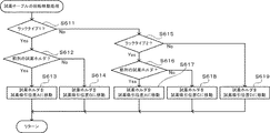
In the reagent dispensing process in step S2-6, the control unit 501 first determines a reagent container (hereinafter referred to as “reagent container R”) in which a reagent to be dispensed according to the analysis item of the sample is stored according to the order information. The reagent table (first reagent table 11 or second reagent table 12) is rotated so that the reagent dispensing arm 120 moves to the reagent suction position (step S61).

図19を用いて、ステップS61における回転移動処理について以下に説明する。制御部501は、まず、RAM501Cに記憶されているバーコード情報および位置情報に基づき、試薬容器Rが保持されている試薬容器ラックがラックタイプ1の試薬容器ラックであるか否かを判断する(ステップS611)。試薬容器Rが保持されている試薬容器ラックがラックタイプ1の試薬容器ラックである場合、次に、試薬容器Rを保持しているホルダが、試薬容器ラックにおける前列(外周側)のホルダであるか否かが判断される(ステップS612)。試薬容器Rを保持しているホルダが、試薬容器ラックにおける前列のホルダである場合には、試薬容器Rを保持しているホルダが試薬吸引位置Aに移動するよう、制御部501は、パルス数N1の駆動パルス信号を第2駆動部503に供給し、第2試薬テーブル12を回転させる(ステップS613)。   The rotational movement process in step S61 will be described below using FIG. First, the control unit 501 determines whether or not the reagent container rack holding the reagent container R is a rack type 1 reagent container rack based on the barcode information and position information stored in the RAM 501C ( Step S611). When the reagent container rack in which the reagent container R is held is a rack container of type 1, the holder holding the reagent container R is the holder in the front row (outer peripheral side) in the reagent container rack. Is determined (step S612). When the holder holding the reagent container R is a front row holder in the reagent container rack, the control unit 501 controls the number of pulses so that the holder holding the reagent container R moves to the reagent suction position A. The drive pulse signal of N1 is supplied to the second drive unit 503, and the second reagent table 12 is rotated (step S613).

制御部501が駆動部(第1駆動部502または第2駆動部503)に供給する駆動パルス信号のパルス数Nは次の式(1)により求められる。   The pulse number N of the drive pulse signal supplied from the control unit 501 to the drive unit (the first drive unit 502 or the second drive unit 503) is obtained by the following equation (1).

N=(L−M)/S・・・(1)
ここで、「L」は、試薬テーブル(第1試薬テーブル11及び第2試薬テーブル12)上の試薬容器Rの位置情報、すなわち、試薬テーブルの原点位置から試薬容器Rまでのズレ量を試薬テーブルの回転角度の値で表すものである。試薬テーブルの回転に応じて試薬容器Rの位置情報は変更するため、「L」の値も試薬テーブルの回転に応じて変更する。「M」は、試薬テーブルの原点位置から試薬分注アーム120による試薬吸引位置までのズレ量を試薬テーブルの回転角度の値で表すものである。「L−M」は、試薬容器Rから試薬分注アーム120による試薬吸引位置までのズレ量を試薬テーブルの回転角度の値で表すものである。「S」は、第1駆動部502の第1ステッピングモータおよび第2駆動部503の第2ステッピングモータのステップ角度(1パルスあたりの回転角度)を表すものである。なお、式(1)では、時計回り方向の回転角度を正の値としている。
N = (LM) / S (1)
Here, “L” indicates the position information of the reagent container R on the reagent table (the first reagent table 11 and the second reagent table 12), that is, the amount of deviation from the origin position of the reagent table to the reagent container R. This is represented by the value of the rotation angle. Since the position information of the reagent container R is changed according to the rotation of the reagent table, the value of “L” is also changed according to the rotation of the reagent table. “M” represents the amount of deviation from the origin position of the reagent table to the reagent suction position by the reagent dispensing arm 120 as a value of the rotation angle of the reagent table. “LM” represents the amount of deviation from the reagent container R to the reagent suction position by the reagent dispensing arm 120 as the value of the rotation angle of the reagent table. “S” represents the step angle (rotation angle per pulse) of the first stepping motor of the first drive unit 502 and the second stepping motor of the second drive unit 503. In equation (1), the clockwise rotation angle is a positive value.

また、本実施形態では、上記の式(1)で用いられた「L−M」の値が180以下であるか、すなわち、
L−M≦180・・・(2)
であるか否かが制御部501により判断される。上記の式(2)が成り立っていると判断されると、試薬テーブルは反時計回りにパルス数Nだけ回転される。上記の式(2)が成り立っていないと判断されると、試薬テーブルは、時計回りに
(360/S)−N・・・(3)
のパルス数だけ回転される。
In the present embodiment, the value of “LM” used in the above formula (1) is 180 or less, that is,
L−M ≦ 180 (2)
It is determined by the control unit 501 whether or not. If it is determined that the above equation (2) holds, the reagent table is rotated counterclockwise by the number of pulses N. If it is determined that the above equation (2) does not hold, the reagent table is rotated clockwise (360 / S) −N (3)
The number of pulses is rotated.

上記の式(1)、式(2)および式(3)を用いて、ステップS613において制御部501が第2駆動部503に供給する駆動パルス信号のパルス数N1、および第2試薬テーブル12の回転方向が決定される。   Using the above equations (1), (2), and (3), the number of pulses N1 of the drive pulse signal that the control unit 501 supplies to the second drive unit 503 in step S613, and the second reagent table 12 The direction of rotation is determined.

ステップS612において、試薬容器Rを保持している試薬ホルダが、試薬容器ラックにおける前列の試薬ホルダでないと判断されると、試薬容器Rを保持している試薬ホルダが試薬吸引位置Bに移動するよう、制御部501は、パルス数N2の駆動パルス信号を第2駆動部503に供給し、第2試薬テーブル12を回転させ(ステップS614)、処理をリターンする。なお、パルス数N2および第2試薬テーブル12の回転方向は、上記の式(1)〜(3)により決定される。   If it is determined in step S612 that the reagent holder holding the reagent container R is not the reagent holder in the front row of the reagent container rack, the reagent holder holding the reagent container R is moved to the reagent suction position B. The control unit 501 supplies the drive pulse signal having the pulse number N2 to the second drive unit 503, rotates the second reagent table 12 (step S614), and returns the process. The number of pulses N2 and the rotation direction of the second reagent table 12 are determined by the above formulas (1) to (3).

ステップS611において、試薬容器Rが保持されている試薬容器ラックがラックタイプ1の試薬容器ラックでない場合、次に、試薬容器Rが保持されている試薬容器ラックがラックタイプ2の試薬容器ラックであるか否かが判断される(ステップS615)。試薬容器Rが保持されている試薬容器ラックがラックタイプ2の試薬容器ラックであると、次に、試薬容器Rを保持しているホルダが、試薬容器ラックにおける前列のホルダであるか否かが判断される(ステップS616)。試薬容器Rを保持しているホルダが、試薬容器ラックにおける前列のホルダである場合、試薬容器Rが試薬吸引位置Aに移動するよう、制御部501は、パルス数N3の駆動パルス信号を第2駆動部503に供給し、第2試薬テーブル12を回転させる(ステップS617)。なお、パルス数N3および第2試薬テーブル12の回転方向は、上記の式(1)〜(3)により決定される。ステップS616において、試薬容器Rを保持しているホルダが、試薬容器ラックにおける前列のホルダでない場合には、試薬容器Rが試薬吸引位置Cに移動するよう、制御部501は、パルス数N4の駆動パルス信号を第2駆動部503に供給し、第2試薬テーブル12を回転させ(ステップS618)、処理をリターンする。なお、パルス数N4および第2試薬テーブル12の回転方向も、上記の式(1)〜(3)により決定される。   In step S611, if the reagent container rack holding the reagent container R is not a rack type 1 reagent container rack, then the reagent container rack holding the reagent container R is a rack type 2 reagent container rack. Is determined (step S615). If the reagent container rack holding the reagent container R is a rack container of type 2, the next step is to determine whether or not the holder holding the reagent container R is a front row holder in the reagent container rack. Determination is made (step S616). When the holder holding the reagent container R is the front row holder in the reagent container rack, the control unit 501 sends the drive pulse signal of the pulse number N3 to the second pulse signal so that the reagent container R moves to the reagent suction position A. The second reagent table 12 is supplied to the drive unit 503 and rotated (step S617). The number of pulses N3 and the rotation direction of the second reagent table 12 are determined by the above formulas (1) to (3). In step S616, if the holder holding the reagent container R is not the front row holder in the reagent container rack, the control unit 501 drives the number of pulses N4 so that the reagent container R moves to the reagent suction position C. A pulse signal is supplied to the 2nd drive part 503, the 2nd reagent table 12 is rotated (step S618), and a process is returned. The number of pulses N4 and the rotation direction of the second reagent table 12 are also determined by the above formulas (1) to (3).

ステップS615において、試薬容器Rが保持されている試薬容器ラックがラックタイプ2の試薬容器ラックでない場合、試薬容器Rが試薬吸引位置Dに移動するよう、制御部501は、パルス数N5の駆動パルス信号を第1駆動部502に供給し、第1試薬テーブル11を回転させ(ステップS619)、処理をリターンする。なお、パルス数N5および第1試薬テーブル11の回転方向も、上記の式(1)〜(3)により決定される。   In step S615, if the reagent container rack holding the reagent container R is not a rack container of type rack 2, the control unit 501 drives the drive pulse with the pulse number N5 so that the reagent container R moves to the reagent suction position D. A signal is supplied to the first drive unit 502, the first reagent table 11 is rotated (step S619), and the process returns. The number of pulses N5 and the rotation direction of the first reagent table 11 are also determined by the above formulas (1) to (3).

ステップS61における試薬テーブルの回転移動処理の後、制御部501は、試薬テーブル上の各試薬容器の位置情報を、試薬テーブルの回転移動処理後の位置情報に更新する(ステップS62)。各試薬容器の位置情報の更新は、試薬容器Rの回転角度と、試薬テーブルの回転移動処理前の各試薬容器の位置情報とに基づき行われる。   After the rotational movement process of the reagent table in step S61, the control unit 501 updates the position information of each reagent container on the reagent table to the positional information after the rotational movement process of the reagent table (step S62). The position information of each reagent container is updated based on the rotation angle of the reagent container R and the position information of each reagent container before the rotational movement process of the reagent table.

次に、制御部501は、試薬吸引位置に試薬分注アーム120が移動するよう、試薬分注駆動部120aを駆動させる(ステップS63)。図20を参照して、試薬分注アーム120の移動処理について以下に説明する。   Next, the control unit 501 drives the reagent dispensing drive unit 120a so that the reagent dispensing arm 120 moves to the reagent aspirating position (step S63). The moving process of the reagent dispensing arm 120 will be described below with reference to FIG.

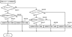
制御部501は、まず、制御装置4の制御部4aに記憶されているバーコード情報に基づき、検体の分析項目に応じた分注対象の試薬が収容される試薬容器(試薬容器R)が保持されている試薬容器ラックがラックタイプ1の試薬容器ラックであるか否かを判断する(ステップS631)。試薬容器Rが保持されている試薬容器ラックがラックタイプ1の試薬容器ラックである場合、次に、試薬容器Rを保持しているホルダが、試薬容器ラックにおける前列のホルダであるか否かが判断される(ステップS632)。試薬容器Rを保持しているホルダが、試薬容器ラックにおける前列のホルダであると、試薬分注アーム120が試薬吸引位置Aに移動するよう、試薬分注駆動部120aが駆動される(ステップS633)。   First, the control unit 501 holds a reagent container (reagent container R) that stores a reagent to be dispensed according to the analysis item of the sample based on the barcode information stored in the control unit 4a of the control device 4. It is determined whether or not the reagent container rack being used is a reagent container rack of rack type 1 (step S631). When the reagent container rack holding the reagent container R is a rack container of type 1 reagent container, next, whether or not the holder holding the reagent container R is a front row holder in the reagent container rack is determined. Determination is made (step S632). If the holder holding the reagent container R is a front row holder in the reagent container rack, the reagent dispensing drive unit 120a is driven so that the reagent dispensing arm 120 moves to the reagent suction position A (step S633). ).

ステップS632において、試薬容器Rを保持しているホルダが、試薬容器ラックにおける前列のホルダでない場合には、試薬分注アーム120が試薬吸引位置Bに移動するよう、制御部501は、試薬分注駆動部120aを駆動し(ステップS614)、処理をリターンする。   In step S632, if the holder holding the reagent container R is not the holder in the front row of the reagent container rack, the control unit 501 causes the reagent dispensing arm 120 to move the reagent dispensing arm 120 to the reagent suction position B. The drive unit 120a is driven (step S614), and the process returns.

ステップS631において、試薬容器Rが保持されている試薬容器ラックがラックタイプ1の試薬容器ラックでない場合、次に、試薬容器Rが保持されている試薬容器ラックがラックタイプ2の試薬容器ラックであるか否かが判断される(ステップS635)。試薬容器Rが保持されている試薬容器ラックがラックタイプ2の試薬容器ラックである場合、次に、試薬容器Rを保持しているホルダが、試薬容器ラックにおける前列のホルダであるか否かが判断される(ステップS636)。試薬容器Rを保持しているホルダが、試薬容器ラックにおける前列のホルダであると、試薬分注アーム120が試薬吸引位置Aに移動するよう、制御部501は、試薬分注駆動部120aを駆動する(ステップS637)。ステップS636において、試薬容器Rを保持しているホルダが、試薬容器ラックにおける前列のホルダでない場合には、試薬分注アーム120が試薬吸引位置Cに移動するよう、制御部501は、試薬分注駆動部120aを駆動し(ステップS638)、処理をリターンする。   If the reagent container rack holding the reagent container R is not a rack type 1 reagent container rack in step S631, then the reagent container rack holding the reagent container R is a rack type 2 reagent container rack. Is determined (step S635). When the reagent container rack holding the reagent container R is a rack container of type 2, the next step is to check whether the holder holding the reagent container R is a front row holder in the reagent container rack. Determination is made (step S636). When the holder holding the reagent container R is a front row holder in the reagent container rack, the control unit 501 drives the reagent dispensing drive unit 120a so that the reagent dispensing arm 120 moves to the reagent suction position A. (Step S637). In step S636, when the holder holding the reagent container R is not the holder in the front row in the reagent container rack, the control unit 501 causes the reagent dispensing arm 120 to move the reagent dispensing arm 120 to the reagent suction position C. The drive unit 120a is driven (step S638), and the process returns.

ステップS635において、試薬容器Rが保持されている試薬容器ラックがタイプ2の試薬容器ラックでない場合、試薬分注アーム120が試薬吸引位置Dに移動するよう、制御部501は、試薬分注駆動部120aを駆動し(ステップS639)、処理をリターンする。   In step S635, when the reagent container rack holding the reagent container R is not a type 2 reagent container rack, the control unit 501 moves the reagent dispensing arm 120 so that the reagent dispensing arm 120 moves to the reagent suction position D. 120a is driven (step S639), and the process returns.

次に、制御部501は、試薬吸引位置に移動した試薬分注アーム120が試薬容器Rから試薬を吸引し、その後、吸引した試薬を所定位置にあるキュベット200に吐出するよう、試薬分注駆動部120aを駆動させる(ステップS64)。次に、制御部501は、試薬分注アーム120が初期位置に移動するよう、試薬分注駆動部120aを駆動させる(ステップS65)。その後、処理をリターンする。   Next, the control unit 501 drives the reagent dispensing so that the reagent dispensing arm 120 moved to the reagent aspirating position sucks the reagent from the reagent container R and then discharges the sucked reagent to the cuvette 200 at a predetermined position. The unit 120a is driven (step S64). Next, the control unit 501 drives the reagent dispensing drive unit 120a so that the reagent dispensing arm 120 moves to the initial position (step S65). Thereafter, the process is returned.

以上のように、本実施形態では、試薬容器ラックのタイプに応じた試薬吸引位置に、分注対象の試薬が収容された試薬容器および試薬分注アーム120が移動するよう、制御部501により試薬テーブルの駆動部および試薬分注駆動部120aが制御される。したがって、試薬容器を保持するホルダの数が異なる複数の試薬容器ラックや、ホルダの位置が異なる複数の試薬容器ラックを試薬テーブル上に配置するとともに、その試薬容器ラックに保持された試薬容器から容易に試薬を吸引することができる。したがって、測定項目数の増加や処理速度の向上にも寄与することができる。   As described above, in this embodiment, the control unit 501 causes the reagent to be moved by the control unit 501 so that the reagent container in which the reagent to be dispensed and the reagent dispensing arm 120 are moved to the reagent suction position corresponding to the type of the reagent container rack. The table drive unit and reagent dispensing drive unit 120a are controlled. Therefore, a plurality of reagent container racks having different numbers of holders for holding reagent containers and a plurality of reagent container racks having different holder positions are arranged on the reagent table, and easily from the reagent containers held in the reagent container racks. The reagent can be aspirated. Therefore, it is possible to contribute to an increase in the number of measurement items and an improvement in processing speed.

また、本実施形態では、試薬容器ラックのタイプに応じて、試薬容器ラックに保持される試薬容器のサイズを変更することができる。そのため、試薬の使用状況に応じて、多様なサイズの試薬容器を用いることができる。   In the present embodiment, the size of the reagent container held in the reagent container rack can be changed according to the type of the reagent container rack. Therefore, reagent containers of various sizes can be used depending on the usage status of the reagent.

また、本実施形態では、試薬容器ラックを特定する識別情報に基づいて、その試薬容器ラックに保持される試薬容器から試薬が吸引される試薬吸引位置を決定している。そのため、試薬吸引位置に関する情報を、各試薬容器のバーコードや各試薬容器ラックのバーコードに予め記録しておく必要がなく、多項目の分析に対しても直ちに対応することができる。   Further, in the present embodiment, based on the identification information specifying the reagent container rack, the reagent suction position at which the reagent is sucked from the reagent container held in the reagent container rack is determined. Therefore, it is not necessary to previously record information on the reagent aspiration position in the barcode of each reagent container or the barcode of each reagent container rack, and it is possible to immediately cope with multi-item analysis.

また、本実施形態では、回転移動可能で試薬容器ラックを配置可能な第1試薬テーブル11と第2試薬テーブル12とが同心円状に配設されているため、より多くの試薬容器を試薬テーブル上に配置することができる。   Further, in the present embodiment, the first reagent table 11 and the second reagent table 12 that can be rotated and arranged with the reagent container rack are arranged concentrically, so that more reagent containers can be placed on the reagent table. Can be arranged.

また、本実施形態では、第2試薬テーブル12に配置可能な第2試薬容器ラック320の外形形状と第3試薬容器ラック330の外形形状とが同じになるよう形成されている。これにより、第2試薬容器ラック320および第3試薬容器ラック330のうちから、第2試薬テーブル12の所定の配置領域に配置する試薬容器ラックを自由に選択することができる。   Further, in this embodiment, the outer shape of the second reagent container rack 320 that can be arranged on the second reagent table 12 and the outer shape of the third reagent container rack 330 are formed to be the same. Thereby, the reagent container rack to be arranged in the predetermined arrangement area of the second reagent table 12 can be freely selected from the second reagent container rack 320 and the third reagent container rack 330.

また、本実施形態では、第2試薬容器ラック320および第3試薬容器ラック330は、試薬容器300を千鳥状に保持可能に構成されている。これにより、第2試薬容器ラック320および第3試薬容器ラック330において試薬容器300をより多く保持できるとともに、試薬バーコードリーダ350による試薬容器300のバーコード300aの読み取りも良好に行うことができる。   In the present embodiment, the second reagent container rack 320 and the third reagent container rack 330 are configured to hold the reagent containers 300 in a zigzag manner. As a result, more reagent containers 300 can be held in the second reagent container rack 320 and the third reagent container rack 330, and the barcode 300a of the reagent container 300 can be satisfactorily read by the reagent barcode reader 350.

また、本実施形態では、第2試薬容器ラック320および第3試薬容器ラック330において、試薬容器300は同心円状に保持されている。そのため、第2試薬テーブル12の回転移動により、第2試薬容器ラック320の前列(外周側)の各ホルダは同一軌道上を回転移動し、後列(内周側)の各ホルダも同一軌道上を回転移動することができる。また、第2試薬テーブル12の回転移動により、第3試薬容器ラック330の前列(外周側)の各ホルダも同一軌道上を回転移動し、後列(内周側)の各ホルダも同一軌道上を回転移動することができる。これにより、試薬分注処理の制御を容易にすることができる。   In the present embodiment, the reagent container 300 is concentrically held in the second reagent container rack 320 and the third reagent container rack 330. Therefore, the rotation of the second reagent table 12 causes the holders in the front row (outer peripheral side) of the second reagent container rack 320 to rotate on the same track, and the holders in the rear row (inner peripheral side) also move on the same track. It can be rotated. Further, the rotational movement of the second reagent table 12 causes the holders in the front row (outer peripheral side) of the third reagent container rack 330 to rotate on the same track, and the holders in the rear row (inner peripheral side) also move on the same track. It can be rotated. Thereby, control of reagent dispensing processing can be facilitated.

また、本実施形態では、試薬分注アーム120は水平方向に回転移動可能に構成されており、試薬分注アーム120による試薬吸引位置は、試薬分注アーム120の回転移動の軌道と、試薬テーブルの回転移動の軌道の交点位置となるよう構成されている。これにより、試薬分注アーム120の駆動制御を簡易にすることができる。   In the present embodiment, the reagent dispensing arm 120 is configured to be able to rotate and move in the horizontal direction. The reagent aspirating position by the reagent dispensing arm 120 includes the rotation movement trajectory of the reagent dispensing arm 120 and the reagent table. It is comprised so that it may become the intersection position of the track | orbit of this rotational movement. Thereby, drive control of the reagent dispensing arm 120 can be simplified.

なお、今回開示された実施形態は、すべての点で例示であって制限的なものではないと考えられるべきである。本発明の範囲は、上記した実施形態の説明ではなく特許請求の範囲によって示され、さらに特許請求の範囲と均等の意味および範囲内でのすべての変更が含まれる。   The embodiment disclosed this time should be considered as illustrative in all points and not restrictive. The scope of the present invention is shown not by the above description of the embodiments but by the scope of claims for patent, and further includes all modifications within the meaning and scope equivalent to the scope of claims for patent.

例えば、上記実施形態では、第1試薬テーブル11には同一タイプの試薬容器ラック310が配置されているが、試薬容器を保持するホルダの数が異なる別のタイプの試薬容器ラックが配置されてもよい。また、ホルダの位置が異なる別のタイプの試薬容器ラックが第1試薬テーブル11に配置されてもよい。   For example, in the above-described embodiment, the same type of reagent container rack 310 is arranged in the first reagent table 11, but another type of reagent container rack having a different number of holders for holding the reagent containers may be arranged. Good. In addition, another type of reagent container rack having a different holder position may be arranged on the first reagent table 11.

また、上記実施形態では、第2試薬テーブル12には、ラックタイプ1の第2試薬容器ラック320と、ラックタイプ2の第3試薬容器ラック330とが配置されているが、ラックタイプ1の試薬容器ラックに代えて、例えば、図21に示すような、ラックタイプ1及びラックタイプ2とホルダの数や位置が異なるラックタイプ3の試薬容器ラックが配置されてもよいし、ラックタイプ2の試薬容器ラックに代えて、ラックタイプ3の試薬容器ラックが配置されてもよい。また、ラックタイプ1およびラックタイプ2の試薬容器ラックに加えて、ラックタイプ3の試薬容器ラックが配置されてもよい。また、ラックタイプ1〜3とホルダの数や位置が異なる他のタイプの試薬容器ラックが配置されてもよい。   In the embodiment described above, the second reagent table 12 includes the rack type 1 second reagent container rack 320 and the rack type 2 third reagent container rack 330, but the rack type 1 reagent. In place of the container rack, for example, as shown in FIG. 21, a reagent container rack of rack type 3 having a different number and position of the holders from rack type 1 and rack type 2 may be arranged. Instead of the container rack, a reagent container rack of rack type 3 may be arranged. In addition to the reagent container racks of rack type 1 and rack type 2, a reagent container rack of rack type 3 may be arranged. Also, other types of reagent container racks having different numbers and positions of holders from rack types 1 to 3 may be arranged.

また、上記実施形態では、第1試薬テーブル11および第2試薬テーブル12の各々は、試薬容器ラックが5つ配置可能に構成されているが、第1試薬テーブル11および第2試薬テーブル12を、試薬容器ラックを5つ以上配置可能に構成してもよい。   In the above embodiment, each of the first reagent table 11 and the second reagent table 12 is configured so that five reagent container racks can be arranged. However, the first reagent table 11 and the second reagent table 12 are You may comprise so that five or more reagent container racks can be arrange | positioned.

また、上記実施形態では、第2試薬容器ラック320および第3試薬容器ラック330にはホルダ(保持部)が同心円状に設けられているが、必ずしもホルダを同心円状に設けなくてもよい。   In the above embodiment, the holders (holding portions) are provided concentrically in the second reagent container rack 320 and the third reagent container rack 330, but the holders are not necessarily provided concentrically.

また、上記実施形態では、試薬分注アーム120が水平方向に回転移動可能に構成されているが、試薬分注アーム120をXY方向に移動可能に構成してもよい。   In the above-described embodiment, the reagent dispensing arm 120 is configured to be able to rotate and move in the horizontal direction. However, the reagent dispensing arm 120 may be configured to be movable in the XY direction.

本発明の一実施形態による検体分析装置の全体構成を示す斜視図である。1 is a perspective view showing an overall configuration of a sample analyzer according to an embodiment of the present invention. 図1に示した検体分析装置の平面図である。It is a top view of the sample analyzer shown in FIG. 本発明の一実施形態による検体分析装置の測定機構部を示す平面図である。It is a top view which shows the measurement mechanism part of the sample analyzer by one Embodiment of this invention. 本発明の一実施形態による検体分析装置の測定機構部および試薬保存部の内部を示す斜視図である。It is a perspective view which shows the inside of the measurement mechanism part and reagent storage part of the sample analyzer by one Embodiment of this invention. 図4に示した測定機構部および試薬保存部の内部を示す平面図である。It is a top view which shows the inside of the measurement mechanism part and reagent storage part which were shown in FIG. 本発明の一実施形態による検体分析装置の制御装置を示すブロック図である。It is a block diagram which shows the control apparatus of the sample analyzer by one Embodiment of this invention. 本発明の一実施形態による制御装置の表示部に表示される試薬管理画面を示す図である。It is a figure which shows the reagent management screen displayed on the display part of the control apparatus by one Embodiment of this invention. 一実施形態による第1試薬容器ラックを示す斜視図である。It is a perspective view which shows the 1st reagent container rack by one Embodiment. 一実施形態による第2試薬容器ラックを示す斜視図であるIt is a perspective view which shows the 2nd reagent container rack by one Embodiment. 図8に示した第1試薬容器ラックに試薬容器が保持された状態を示す斜視図である。FIG. 9 is a perspective view showing a state in which a reagent container is held in the first reagent container rack shown in FIG. 8. 図9に示した第2試薬容器ラックに試薬容器が保持された状態を示す斜視図である。FIG. 10 is a perspective view showing a state in which the reagent container is held in the second reagent container rack shown in FIG. 9. ラックタイプ1である図9に示した第2試薬容器ラックの模式図である。FIG. 10 is a schematic diagram of the second reagent container rack shown in FIG. ラックタイプ2である第3試薬容器ラックの模式図である。6 is a schematic diagram of a third reagent container rack that is rack type 2. FIG. 本発明の一実施形態による検体分析装置のブロック図である。1 is a block diagram of a sample analyzer according to an embodiment of the present invention. 本発明の一実施形態による検体分析装置の測定機構部の制御部のブロック図である。It is a block diagram of the control part of the measurement mechanism part of the sample analyzer by one Embodiment of this invention. 本発明の一実施形態による検体分析装置の制御装置4の制御部4aおよび測定機構部2の制御部501の測定処理フローを示すフローチャートである。It is a flowchart which shows the measurement process flow of the control part 4a of the control apparatus 4 of the sample analyzer by one Embodiment of this invention, and the control part 501 of the measurement mechanism part 2. FIG. 本発明の一実施形態による測定機構部2の制御部501による初期化処理を示すフローチャートである。It is a flowchart which shows the initialization process by the control part 501 of the measurement mechanism part 2 by one Embodiment of this invention. 本発明の一実施形態による測定機構部2の制御部501による試薬分注処理を示すフローチャートである。It is a flowchart which shows the reagent dispensing process by the control part 501 of the measurement mechanism part 2 by one Embodiment of this invention. 本発明の一実施形態による測定機構部2の制御部501による試薬テーブルの回転移動処理を示すフローチャートである。It is a flowchart which shows the rotational movement process of the reagent table by the control part 501 of the measurement mechanism part 2 by one Embodiment of this invention. 本発明の一実施形態による測定機構部2の制御部501による試薬分注アームの移動処理を示すフローチャートである。It is a flowchart which shows the movement process of the reagent dispensing arm by the control part 501 of the measurement mechanism part 2 by one Embodiment of this invention. ラックタイプ3の試薬容器ラックを示す模式図である。FIG. 6 is a schematic diagram showing a reagent container rack of rack type 3.

符号の説明Explanation of symbols

1 検体分析装置
2 測定機構部
3 搬送機構部
4 制御装置
4a 制御部
11 第1試薬テーブル
12 第2試薬テーブル
120 試薬分注アーム
120a 試薬分注駆動部
120b ステッピングモータ部
300 試薬容器
310 第1試薬容器ラック
320 第2試薬容器ラック
330 第3試薬容器ラック
350 試薬バーコードリーダ
501 制御部
502 第1駆動部
503 第2駆動部
DESCRIPTION OF SYMBOLS 1 Sample analyzer 2 Measurement mechanism part 3 Conveyance mechanism part 4 Control apparatus 4a Control part 11 1st reagent table 12 2nd reagent table 120 Reagent dispensing arm 120a Reagent dispensing drive part 120b Stepping motor part 300 Reagent container 310 1st reagent Container rack 320 Second reagent container rack 330 Third reagent container rack 350 Reagent barcode reader 501 Control unit 502 First drive unit 503 Second drive unit

Claims (9)

検体を所定の分析項目に応じた試薬を用いて分析する検体分析装置であって、
複数の試薬容器ラックを保持するための環状のラック配置部を備えた回転テーブルと、
ラック配置部に保持されたときに、第1の試薬吸引位置に対応した位置に、識別子が付された試薬容器を保持するための複数の試薬容器保持部を備え、識別子が付された第1試薬容器ラックと、
第1試薬吸引位置とは異なる第2の試薬吸引位置に対応した位置に、識別子が付された試薬容器を保持するための複数の試薬容器保持部を備え、識別子が付された第2試薬容器ラックと、
回転テーブルを回転駆動するための回転テーブル駆動手段と、
第1および第2試薬容器ラックに付された識別子ならびに第1および第2試薬容器ラックに保持された各試薬容器に付された識別子から試薬容器ラックおよび試薬を特定する識別情報を取得する識別情報取得手段と、
識別情報取得手段によって取得された識別情報に基づいて回転テーブル上の試薬容器位置情報を取得する位置情報取得手段と、
識別情報取得手段によって取得された識別情報、および位置情報取得手段によって取得された試薬容器位置情報を格納する記憶手段と、
第1試薬吸引位置および第2試薬吸引位置に移動可能に設けられており、試薬容器から試薬を吸引するための吸引部と、
吸引部を移動させるための吸引部移動手段と、
分析に用いる対象試薬が保持されたラックのラック識別情報および試薬容器位置情報を記憶手段から読み出して、対象試薬が保持されたラックが第1試薬容器ラックの場合は、第1試薬吸引位置に吸引部を移動させるように吸引部移動手段を制御すると共に対象試薬を第1試薬吸引位置に移動させるように回転テーブル駆動手段を制御し、対象試薬が保持されたラックが第2試薬容器ラックの場合は、第2試薬吸引位置に吸引部を移動させるように吸引部移動手段を制御すると共に対象試薬を第2試薬吸引位置に移動させるように回転テーブル駆動手段を制御する駆動制御部と、を備えた検体分析装置。
A sample analyzer for analyzing a sample using a reagent according to a predetermined analysis item,
A rotary table provided with an annular rack arrangement portion for holding a plurality of reagent container racks;
A plurality of reagent container holding portions for holding reagent containers with identifiers are provided at positions corresponding to the first reagent suction positions when held by the rack arrangement section, and the first identifiers are attached. A reagent container rack;
A second reagent container having an identifier provided with a plurality of reagent container holding portions for holding the reagent container to which the identifier is attached at a position corresponding to a second reagent suction position different from the first reagent suction position Rack,
Rotary table driving means for driving the rotary table to rotate;
Identification information for acquiring identification information for identifying the reagent container rack and the reagent from the identifiers attached to the first and second reagent container racks and the identifiers attached to the reagent containers held in the first and second reagent container racks Acquisition means;
Position information acquisition means for acquiring reagent container position information on the rotary table based on the identification information acquired by the identification information acquisition means;
Storage means for storing the identification information acquired by the identification information acquisition means and the reagent container position information acquired by the position information acquisition means;
A suction part which is provided so as to be movable to a first reagent suction position and a second reagent suction position, and for sucking the reagent from the reagent container;
Suction part moving means for moving the suction part;
The rack identification information and reagent container position information of the rack holding the target reagent used for analysis is read from the storage means, and if the rack holding the target reagent is the first reagent container rack, the rack is aspirated to the first reagent suction position. When the suction part moving means is controlled to move the part and the rotary table driving means is controlled to move the target reagent to the first reagent suction position, and the rack holding the target reagent is the second reagent container rack Includes a drive control unit that controls the suction unit moving unit to move the suction unit to the second reagent suction position and controls the rotary table drive unit to move the target reagent to the second reagent suction position. Sample analyzer.
第1試薬容器ラックは、第2試薬容器ラックとは異なる数の試薬容器保持部を有する請求項1記載の検体分析装置。   The sample analyzer according to claim 1, wherein the first reagent container rack has a different number of reagent container holding units from the second reagent container rack. 第1試薬容器ラックは第2試薬容器ラックと同じ外形形状を有する請求項1または請求項2に記載の検体分析装置。   The sample analyzer according to claim 1 or 2, wherein the first reagent container rack has the same outer shape as the second reagent container rack. 第1試薬容器ラックは、第1試薬吸引位置に対応し回転テーブルの同心円の円弧上に配置される複数の第1試薬容器保持部と、第1及び第2試薬吸引位置とは異なる第3試薬吸引位置に対応し回転テーブルの同心円の円弧上に配置される複数の第2試薬容器保持部とを備える請求項1〜3のいずれか1項に記載の検体分析装置。   The first reagent container rack includes a plurality of first reagent container holding portions disposed on a concentric arc of the rotary table corresponding to the first reagent suction position, and a third reagent different from the first and second reagent suction positions. The sample analyzer according to any one of claims 1 to 3, further comprising a plurality of second reagent container holders arranged on a concentric arc of the rotary table corresponding to the suction position. 第1試薬容器保持部と第2試薬容器保持部はそれぞれ千鳥状に配置される請求項1〜4のいずれか1項に記載の検体分析装置。   The sample analyzer according to any one of claims 1 to 4, wherein the first reagent container holding part and the second reagent container holding part are arranged in a staggered manner. 記憶手段は、試薬容器ラックの種類と、ラック内の各試薬容器保持部の位置情報を予め記憶している請求項1〜5のいずれか1項に記載の検体分析装置。   The sample analyzer according to any one of claims 1 to 5, wherein the storage unit stores in advance the type of reagent container rack and position information of each reagent container holding unit in the rack. 吸引部は水平面内を回転移動可能に構成されており、第1試薬吸引位置は、吸引部の回転移動の軌道と、回転テーブルの回転移動による第1試薬容器ラックの試薬容器保持部の回転移動の軌道との交点位置であり、第2試薬吸引位置は、吸引部の回転移動の軌道と、回転テーブルの回転移動による第2試薬容器ラックの試薬容器保持部の回転移動の軌道との交点位置である請求項1〜6のいずれか1項に記載の検体分析装置。   The suction part is configured to be able to rotate and move in a horizontal plane, and the first reagent suction position is the rotational movement of the suction part and the rotational movement of the reagent container holding part of the first reagent container rack by the rotational movement of the rotary table. The second reagent suction position is the position of the intersection of the rotational movement of the suction part and the rotational movement of the reagent container holding part of the second reagent container rack by the rotational movement of the rotary table. The sample analyzer according to any one of claims 1 to 6. 第1試薬吸引位置および第2試薬吸引位置とは異なる第4の試薬吸引位置に対応した位置に、識別子が付された試薬容器を保持するための試薬容器保持部を備え、識別子が付された第3試薬容器ラックと、第3試薬容器ラックを配置するための環状のラック配置部を備え、前記回転テーブルの内側に同心円状に配設されると共に、前記回転テーブルとは独立して回転可能に設けられた第2回転テーブルをさらに備える請求項1〜7のいずれか1項に記載の検体分析装置。   A reagent container holding unit for holding a reagent container to which an identifier is attached is provided at a position corresponding to a fourth reagent suction position different from the first reagent suction position and the second reagent suction position, and the identifier is attached. A third reagent container rack and an annular rack arrangement part for arranging the third reagent container rack are provided, arranged concentrically inside the rotary table, and rotatable independently of the rotary table. The sample analyzer according to any one of claims 1 to 7, further comprising a second rotary table provided in the apparatus. ラック配置部に保持されたときに、第1の試薬吸引位置に対応した位置に、識別子が付された試薬容器を保持するための複数の試薬容器保持部を備え、識別子が付された第1試薬容器ラックと、第1試薬吸引位置とは異なる第2の試薬吸引位置に対応した位置に、識別子が付された試薬容器を保持するための複数の試薬容器保持部を備え、識別子が付された第2試薬容器ラックとを、複数の試薬容器ラックを保持するための環状のラック配置部を備えた回転テーブルに配置する工程と、
第1および第2試薬容器ラックに付された識別子ならびに第1および第2試薬容器ラックに保持された各試薬容器に付された識別子から試薬容器ラックおよび試薬を特定する識別情報を取得する工程と、
識別情報取得手段によって取得された識別情報に基づいて回転テーブル上の試薬容器位置情報を取得する工程と、
識別情報取得手段によって取得された識別情報、および位置情報取得手段によって取得された試薬容器位置情報を記憶手段に記憶する工程と、
吸引の対象試薬が保持されたラックのラック識別情報および試薬容器位置情報を記憶手段から読み出して、対象試薬が保持されたラックが第1試薬容器ラックの場合は、第1試薬吸引位置に吸引部を移動させると共に対象試薬を第1試薬吸引位置に移動させるように回転テーブルを回転させ、対象試薬が保持されたラックが第2試薬容器ラックの場合は、第2試薬吸引位置に吸引部を移動させると共に対象試薬を第2試薬吸引位置に移動させるように回転テーブルを回転させる工程と、を備えた試薬吸引方法。
A plurality of reagent container holding portions for holding reagent containers with identifiers are provided at positions corresponding to the first reagent suction positions when held by the rack arrangement section, and the first identifiers are attached. A reagent container rack and a plurality of reagent container holding portions for holding reagent containers with identifiers are provided at positions corresponding to a second reagent suction position different from the first reagent suction position. Placing the second reagent container rack on a turntable having an annular rack placement portion for holding a plurality of reagent container racks;
Obtaining identification information identifying the reagent container rack and the reagent from the identifier attached to the first and second reagent container racks and the identifier attached to each reagent container held in the first and second reagent container racks; ,
Acquiring reagent container position information on the rotary table based on the identification information acquired by the identification information acquisition means;
Storing the identification information acquired by the identification information acquisition means and the reagent container position information acquired by the position information acquisition means in the storage means;
The rack identification information and reagent container position information of the rack in which the target reagent to be aspirated is read out from the storage means, and when the rack in which the target reagent is held is the first reagent container rack, the aspirator is placed at the first reagent aspiration position. The rotary table is rotated so that the target reagent is moved to the first reagent suction position, and when the rack holding the target reagent is the second reagent container rack, the suction part is moved to the second reagent suction position. And rotating the rotary table so as to move the target reagent to the second reagent suction position.
JP2007089300A 2007-03-29 2007-03-29 Sample analyzer and reagent aspiration method Active JP4876010B2 (en)

Priority Applications (4)

Application Number Priority Date Filing Date Title
JP2007089300A JP4876010B2 (en) 2007-03-29 2007-03-29 Sample analyzer and reagent aspiration method
EP08005574.2A EP1975630A3 (en) 2007-03-29 2008-03-26 Sample analyzer, reagent aspirating method, and computer program product
US12/079,789 US8277729B2 (en) 2007-03-29 2008-03-27 Sample analyzer, reagent aspirating method, and computer program product
CN2008100848960A CN101275965B (en) 2007-03-29 2008-03-28 Sample analyzer, reagent aspirating method

Applications Claiming Priority (1)

Application Number Priority Date Filing Date Title
JP2007089300A JP4876010B2 (en) 2007-03-29 2007-03-29 Sample analyzer and reagent aspiration method

Publications (2)

Publication Number Publication Date
JP2008249414A JP2008249414A (en) 2008-10-16
JP4876010B2 true JP4876010B2 (en) 2012-02-15

Family

ID=39531399

Family Applications (1)

Application Number Title Priority Date Filing Date
JP2007089300A Active JP4876010B2 (en) 2007-03-29 2007-03-29 Sample analyzer and reagent aspiration method

Country Status (4)

Country Link
US (1) US8277729B2 (en)
EP (1) EP1975630A3 (en)
JP (1) JP4876010B2 (en)
CN (1) CN101275965B (en)

Families Citing this family (39)

* Cited by examiner, † Cited by third party
Publication number Priority date Publication date Assignee Title
US8296088B2 (en) * 2006-06-02 2012-10-23 Luminex Corporation Systems and methods for performing measurements of one or more materials
JP2009180607A (en) * 2008-01-30 2009-08-13 Olympus Corp Automatic analyzer
JP5128441B2 (en) * 2008-11-07 2013-01-23 株式会社イードクトル Linking device for blood collection tube identification
DE112009003625B4 (en) * 2008-11-21 2013-07-25 Hitachi High-Technologies Corporation Automatic analyzer
JP5341492B2 (en) * 2008-12-17 2013-11-13 シスメックス株式会社 Sample processing system, sample processing method, and computer program
JP5323467B2 (en) * 2008-12-16 2013-10-23 シスメックス株式会社 Sample processing system
JP5355362B2 (en) * 2008-12-22 2013-11-27 シスメックス株式会社 Specimen inspection system, specimen inspection method and computer program
JP5618489B2 (en) * 2009-02-17 2014-11-05 シスメックス株式会社 Analysis device, analysis method, and computer program
JP5441544B2 (en) * 2009-07-24 2014-03-12 シスメックス株式会社 Sample analyzer and preparation method
JP5553554B2 (en) * 2009-08-27 2014-07-16 シスメックス株式会社 Sample analyzer
JP5346265B2 (en) * 2009-09-30 2013-11-20 シスメックス株式会社 Sample analyzer and sample analysis method
CN102762988B (en) * 2010-01-28 2015-02-25 株式会社日立高新技术 Automatic analyzing device
JP5340975B2 (en) * 2010-01-29 2013-11-13 株式会社日立ハイテクノロジーズ Automatic analyzer
CN102221626B (en) * 2010-04-14 2015-04-22 深圳迈瑞生物医疗电子股份有限公司 Automatic biochemistry analyzer and working method thereof
JP5485014B2 (en) * 2010-05-14 2014-05-07 株式会社東芝 Automatic analyzer
JP5396378B2 (en) * 2010-12-24 2014-01-22 株式会社日立ハイテクノロジーズ Automatic analyzer
EP2546655B1 (en) * 2011-07-13 2019-12-04 F. Hoffmann-La Roche AG Instrument and process for the automated processing of liquid samples
EP2746775B1 (en) * 2012-12-19 2019-09-04 F.Hoffmann-La Roche Ag Device and process for transferring reaction vessels
AU2013202782B2 (en) * 2013-03-14 2015-05-14 Gen-Probe Incorporated Apparatus for indexing and agitating fluid containers
WO2016130962A1 (en) 2015-02-13 2016-08-18 Abbott Laboratories Automated storage modules for diagnostic analyzer liquids and related systems and methods
CN108027280B (en) 2015-06-26 2021-07-06 雅培实验室 Reaction vessel movement component for moving a reaction vessel from a processing track to a rotation device in a diagnostic analyzer
EP3314269A4 (en) 2015-06-26 2019-01-23 Abbott Laboratories Reaction vessel exchanger device for a diagnostic analyzer
KR20240042224A (en) 2015-08-06 2024-04-01 엘리멘탈 사이언티픽, 인코포레이티드 Autosampler sample and sample rack identification
ES2877147T3 (en) 2016-02-17 2021-11-16 Becton Dickinson Co Automated methods and modules for preanalytical processing of biological samples for analysis
WO2017159359A1 (en) * 2016-03-16 2017-09-21 株式会社 日立ハイテクノロジーズ Automated analysis device
EP3446129B1 (en) 2016-04-22 2024-02-14 Becton, Dickinson and Company Automated diagnostic analyzer and method for its operation
CN109073669B (en) 2016-04-22 2022-11-25 贝克顿·迪金森公司 Automated diagnostic analyzer and method for operation of an automated diagnostic analyzer
EP3517973B1 (en) * 2016-09-21 2023-10-11 Hitachi High-Tech Corporation Automatic analyzer
CN116273219A (en) 2017-03-03 2023-06-23 简·探针公司 Evaporation limiting insert for a reagent container and related method of use
CN106892142B (en) * 2017-03-14 2019-03-22 广州冠科生物科技有限公司 The method for filling of liquid subpackage device
JP6903484B2 (en) * 2017-05-09 2021-07-14 キヤノンメディカルシステムズ株式会社 Automatic analyzer
CN107367622B (en) * 2017-06-28 2018-10-19 苏州长光华医生物医学工程有限公司 Full-automatic blood type analysis system
CN107167620B (en) * 2017-06-28 2018-05-04 苏州长光华医生物医学工程有限公司 A kind of blood group instrument reagent sample storage dish
CN107271695B (en) * 2017-06-28 2018-10-16 苏州长光华医生物医学工程有限公司 A kind of blood type analytical instrument
WO2019000708A1 (en) * 2017-06-28 2019-01-03 苏州长光华医生物医学工程有限公司 Blood type analyzer
CN107228950B (en) * 2017-06-28 2018-09-11 苏州长光华医生物医学工程有限公司 A kind of blood group instrument reagent sample storing mechanism
CN111542742B (en) 2017-11-27 2022-01-11 徕卡生物系统成像股份有限公司 Slide rack determination system
CN112881741A (en) * 2019-11-29 2021-06-01 深圳市帝迈生物技术有限公司 Method and device for controlling reagent transfer device, sample analyzer, and medium
WO2024006490A1 (en) * 2022-07-01 2024-01-04 Beckman Coulter, Inc. Consumables container loading/unloading system

Family Cites Families (24)

* Cited by examiner, † Cited by third party
Publication number Priority date Publication date Assignee Title
JP3193443B2 (en) * 1992-04-24 2001-07-30 オリンパス光学工業株式会社 Automatic analyzer
JP3267365B2 (en) * 1993-01-29 2002-03-18 株式会社東芝 Multi-rotating sampler
JP3063564B2 (en) * 1995-03-17 2000-07-12 株式会社日立製作所 Automatic analyzer
JPH08313538A (en) * 1995-05-22 1996-11-29 Mitsubishi Corp Automatic analytical instrument
JP2988362B2 (en) * 1996-03-11 1999-12-13 株式会社日立製作所 Multi-sample analysis system
JPH09297147A (en) * 1996-05-07 1997-11-18 Shimadzu Corp Automatic chemical analysis device
JPH11281650A (en) * 1998-03-31 1999-10-15 Olympus Optical Co Ltd Member detecting apparatus
JP2001116757A (en) * 1999-10-19 2001-04-27 Toshiba Corp Autoanalyzer
EP1291659A3 (en) * 2001-09-06 2008-05-21 Sysmex Corporation Automatic sample analyzer and its components
JP3300704B2 (en) * 2001-09-25 2002-07-08 株式会社東芝 Automatic analyzer and method
US6998247B2 (en) * 2002-03-08 2006-02-14 Sensys Medical, Inc. Method and apparatus using alternative site glucose determinations to calibrate and maintain noninvasive and implantable analyzers
JP4117181B2 (en) * 2002-11-21 2008-07-16 株式会社日立ハイテクノロジーズ Automatic analyzer
JP4098174B2 (en) * 2003-07-16 2008-06-11 シスメックス株式会社 Analysis equipment
JP3848938B2 (en) 2003-07-25 2006-11-22 株式会社日立ハイテクノロジーズ Automatic analyzer
JP4146780B2 (en) * 2003-10-17 2008-09-10 株式会社日立ハイテクノロジーズ Reagent cassette and automatic analyzer using the same
JP3980031B2 (en) * 2005-02-09 2007-09-19 株式会社日立製作所 Automatic analyzer
US9243993B2 (en) * 2005-03-17 2016-01-26 Sysmex Corporation Sample analyzer and sample analyzing method
JP4755874B2 (en) * 2005-09-27 2011-08-24 シスメックス株式会社 SAMPLE ANALYZER, SAMPLE ANALYSIS PROCESSING COMPUTER, METHOD FOR DISPLAYING OPERATION SCREEN IN SAMPLE ANALYZER, AND COMPUTER PROGRAM FOR SAMPLE ANALYZER PROCESSING COMPUTER
JP4768409B2 (en) * 2005-11-15 2011-09-07 シスメックス株式会社 Sample analysis apparatus, sample analysis main body apparatus, and sample container supply apparatus
JP4851267B2 (en) * 2006-08-18 2012-01-11 シスメックス株式会社 Sample analyzer
JP2008058123A (en) * 2006-08-31 2008-03-13 Hitachi High-Technologies Corp Autoanalyzer
EP3260842B1 (en) * 2007-02-01 2022-04-13 Sysmex Corporation Hematological analyzer and method for analyzing a sample
JP5032150B2 (en) * 2007-02-22 2012-09-26 シスメックス株式会社 Sample processing equipment
JP5162177B2 (en) * 2007-07-31 2013-03-13 シスメックス株式会社 Particle analyzer and particle analysis method

Also Published As

Publication number Publication date
US8277729B2 (en) 2012-10-02
EP1975630A3 (en) 2017-08-02
JP2008249414A (en) 2008-10-16
CN101275965B (en) 2012-03-07
EP1975630A2 (en) 2008-10-01
CN101275965A (en) 2008-10-01
US20080241939A1 (en) 2008-10-02

Similar Documents

Publication Publication Date Title
JP4876010B2 (en) Sample analyzer and reagent aspiration method
JP4851266B2 (en) Sample analyzer
JP5009684B2 (en) Sample analyzer
US20210063421A1 (en) Sample analyzer
JP5280797B2 (en) Sample analyzer
JP5203141B2 (en) Sample analyzer, method for displaying reagent information in sample analyzer, and computer program
JP5210800B2 (en) Sample analyzer, reagent information display method and computer program in sample analyzer
JP4980671B2 (en) Blood sample analyzer
JP4969293B2 (en) Sample analyzer
JP5600487B2 (en) Sample analyzer and liquid suction method
JP4817181B2 (en) Sample analyzer and identifier reading method
JP2008275585A (en) Sample analyzer
JP5336555B2 (en) Sample analyzer
JP2023018144A (en) automatic analyzer
JP5722406B2 (en) Sample analyzer
JP2012132932A (en) Blood analyzer and blood analysis system

Legal Events

Date Code Title Description
A621 Written request for application examination

Free format text: JAPANESE INTERMEDIATE CODE: A621

Effective date: 20100225

RD04 Notification of resignation of power of attorney

Free format text: JAPANESE INTERMEDIATE CODE: A7424

Effective date: 20110812

A977 Report on retrieval

Free format text: JAPANESE INTERMEDIATE CODE: A971007

Effective date: 20111019

TRDD Decision of grant or rejection written
A01 Written decision to grant a patent or to grant a registration (utility model)

Free format text: JAPANESE INTERMEDIATE CODE: A01

Effective date: 20111101

A01 Written decision to grant a patent or to grant a registration (utility model)

Free format text: JAPANESE INTERMEDIATE CODE: A01

A61 First payment of annual fees (during grant procedure)

Free format text: JAPANESE INTERMEDIATE CODE: A61

Effective date: 20111128

FPAY Renewal fee payment (event date is renewal date of database)

Free format text: PAYMENT UNTIL: 20141202

Year of fee payment: 3

R150 Certificate of patent or registration of utility model

Ref document number: 4876010

Country of ref document: JP

Free format text: JAPANESE INTERMEDIATE CODE: R150

Free format text: JAPANESE INTERMEDIATE CODE: R150

R250 Receipt of annual fees

Free format text: JAPANESE INTERMEDIATE CODE: R250

R250 Receipt of annual fees

Free format text: JAPANESE INTERMEDIATE CODE: R250

R250 Receipt of annual fees

Free format text: JAPANESE INTERMEDIATE CODE: R250

R250 Receipt of annual fees

Free format text: JAPANESE INTERMEDIATE CODE: R250