JP4871292B2 - System for visualizing anatomical tree structures - Google Patents
System for visualizing anatomical tree structures Download PDFInfo
- Publication number
- JP4871292B2 JP4871292B2 JP2007542441A JP2007542441A JP4871292B2 JP 4871292 B2 JP4871292 B2 JP 4871292B2 JP 2007542441 A JP2007542441 A JP 2007542441A JP 2007542441 A JP2007542441 A JP 2007542441A JP 4871292 B2 JP4871292 B2 JP 4871292B2
- Authority
- JP
- Japan
- Prior art keywords
- tree structure
- anatomical tree
- anatomical
- visualization
- planar
- Prior art date
- Legal status (The legal status is an assumption and is not a legal conclusion. Google has not performed a legal analysis and makes no representation as to the accuracy of the status listed.)
- Active
Links
- 238000012800 visualization Methods 0.000 claims description 27
- 238000012545 processing Methods 0.000 claims description 9
- 238000004590 computer program Methods 0.000 claims description 6
- 230000002452 interceptive effect Effects 0.000 claims description 4
- 230000011218 segmentation Effects 0.000 claims description 3
- 230000002792 vascular Effects 0.000 claims description 3
- 210000001147 pulmonary artery Anatomy 0.000 claims description 2
- 230000003247 decreasing effect Effects 0.000 claims 2
- 238000000034 method Methods 0.000 description 18
- 238000013507 mapping Methods 0.000 description 16
- 210000004072 lung Anatomy 0.000 description 7
- 210000000621 bronchi Anatomy 0.000 description 6
- 210000003437 trachea Anatomy 0.000 description 5
- 238000010586 diagram Methods 0.000 description 4
- 238000002059 diagnostic imaging Methods 0.000 description 3
- 230000005856 abnormality Effects 0.000 description 2
- 210000001367 artery Anatomy 0.000 description 2
- 230000007423 decrease Effects 0.000 description 2
- 239000000284 extract Substances 0.000 description 2
- 238000002603 single-photon emission computed tomography Methods 0.000 description 2
- 238000011179 visual inspection Methods 0.000 description 2
- 208000010378 Pulmonary Embolism Diseases 0.000 description 1
- 208000007536 Thrombosis Diseases 0.000 description 1
- 238000010521 absorption reaction Methods 0.000 description 1
- 238000004458 analytical method Methods 0.000 description 1
- 210000003484 anatomy Anatomy 0.000 description 1
- 238000002583 angiography Methods 0.000 description 1
- 238000013459 approach Methods 0.000 description 1
- 238000013170 computed tomography imaging Methods 0.000 description 1
- 230000007547 defect Effects 0.000 description 1
- 230000007812 deficiency Effects 0.000 description 1
- 230000006870 function Effects 0.000 description 1
- 238000003384 imaging method Methods 0.000 description 1
- 238000007689 inspection Methods 0.000 description 1
- 238000012544 monitoring process Methods 0.000 description 1
- 230000002685 pulmonary effect Effects 0.000 description 1
- 230000003068 static effect Effects 0.000 description 1
- 238000003325 tomography Methods 0.000 description 1
Images


Classifications
-
- G—PHYSICS
- G06—COMPUTING; CALCULATING OR COUNTING
- G06T—IMAGE DATA PROCESSING OR GENERATION, IN GENERAL
- G06T7/00—Image analysis
- G06T7/10—Segmentation; Edge detection
- G06T7/11—Region-based segmentation
-
- G—PHYSICS
- G06—COMPUTING; CALCULATING OR COUNTING
- G06T—IMAGE DATA PROCESSING OR GENERATION, IN GENERAL
- G06T2207/00—Indexing scheme for image analysis or image enhancement
- G06T2207/10—Image acquisition modality
- G06T2207/10072—Tomographic images
- G06T2207/10081—Computed x-ray tomography [CT]
-
- G—PHYSICS
- G06—COMPUTING; CALCULATING OR COUNTING
- G06T—IMAGE DATA PROCESSING OR GENERATION, IN GENERAL
- G06T2207/00—Indexing scheme for image analysis or image enhancement
- G06T2207/30—Subject of image; Context of image processing
- G06T2207/30004—Biomedical image processing
- G06T2207/30101—Blood vessel; Artery; Vein; Vascular
Landscapes
- Engineering & Computer Science (AREA)
- Computer Vision & Pattern Recognition (AREA)
- Physics & Mathematics (AREA)
- General Physics & Mathematics (AREA)
- Theoretical Computer Science (AREA)
- Apparatus For Radiation Diagnosis (AREA)
Description
本発明は一般的に、医療撮像の分野に関する。特に本発明は、解剖学的ツリー(anatomical tree)構造の平面角視覚化(planar angular visualization)に対する方法及び装置、並びに三次元の肺の気管支樹構造の平面位相マッピングに関係している。 The present invention relates generally to the field of medical imaging. In particular, the present invention relates to methods and apparatus for planar angular visualization of anatomical tree structures, and planar phase mapping of three-dimensional pulmonary bronchial tree structures.
ヘリカルCT撮像において、被験者の周りにX線源のらせん軌道を実現するためのガントリ回転平面に垂直な方向に沿って検査領域を通り線形に患者が進められる。このらせん軌道中に得られるX線吸収データは、被験者又は被験者の選択した部分の三次元画像表示を生成するために、フィルター補正逆投影法又は他の再構成方法を使用して再構成される。 In helical CT imaging, the patient is linearly advanced through the examination region along a direction perpendicular to the gantry rotation plane for realizing the helical trajectory of the X-ray source around the subject. X-ray absorption data obtained during this helical trajectory is reconstructed using a filtered backprojection method or other reconstruction method to generate a three-dimensional image representation of the subject or a selected portion of the subject. .
マルチスライススキャナからの高解像度のCTデータセットは、診断目的で気管支の検査をより小さな気道に落とし込むことを可能にする。結果生じる画像は、気管支の気道内腔(airway lumen)及び壁部の厚さを検査するのに使用されることができる。 A high-resolution CT data set from a multi-slice scanner allows bronchial examinations to be dropped into smaller airways for diagnostic purposes. The resulting image can be used to inspect the airway lumen and wall thickness of the bronchi.
気管支樹構造は、数百のサブセグメントを含んでいる。これにより、三次元の気管支樹における全ての経路の目視検査は非常に時間がかかる。他方、前記三次元ツリーの平面投影は、図1に説明されるように多数の閉塞をまねき、このツリーの繊細な構造のせいで特定の気道路の続きを辿るのは難しい。 The bronchial tree structure includes hundreds of subsegments. Thus, visual inspection of all paths in the three-dimensional bronchial tree is very time consuming. On the other hand, the planar projection of the three-dimensional tree leads to numerous blockages as illustrated in FIG. 1, and it is difficult to follow the continuation of a particular airway because of the delicate structure of the tree.
故に、本発明の目的は、三次元の解剖学的ツリーの改善した表示を供給するシステム及び方法を提供することである。 Accordingly, it is an object of the present invention to provide a system and method that provides an improved representation of a three-dimensional anatomical tree.
従って、本発明は好ましくは、従来の上記欠陥及び欠点の1つ以上を単独で又は何れかの組み合わせで軽減、緩和又は削除しようとすると共に、添付する請求項による解剖学的ツリーの平面角視覚化を提供するシステム、画像取得装置、方法、コンピュータ読み取り可能媒体及び画像ワークステーションを提供することにより上述した問題を少なくとも解決することである。 Accordingly, the present invention preferably seeks to mitigate, alleviate or eliminate one or more of the above-mentioned deficiencies and shortcomings, alone or in any combination, and provides planar angle vision of an anatomical tree according to the appended claims. An object of the present invention is to at least solve the above-mentioned problems by providing a system, an image acquisition device, a method, a computer readable medium and an image workstation.
本発明の一般的な解決法は、セグメントの閉塞又は交差が起こらず、サブセグメントの階層が導出可能であり、それが肺の葉部(lobe)のような本当の解剖学的範囲に類似点を運ぶような肺の三次元の気管支樹構造の平面位相マッピングを提案している。従来の幾何学的な3Dto2D投影とは対照的に、このマップは、例えば全ての気管支セグメントの竜骨(carina)への選択した距離を変化させるGUIスライダを介するような低い自由度でビュー内において気管支樹の検査を可能にする。 The general solution of the present invention is that segment occlusion or crossing does not occur and the sub-segment hierarchy can be derived, which is similar to a true anatomical range such as a lobe of the lung We propose a planar phase mapping of the three-dimensional bronchial tree structure of the lung. In contrast to conventional geometric 3D to 2D projections, this map can be used in bronchial views within the view with a low degree of freedom, for example via a GUI slider that changes the selected distance of all bronchial segments to the carina. Allows inspection of trees.
本発明のある態様によれば、以下のステップを有する解剖学的ツリー構造を視覚化する方法が提供される。この解剖学的ツリー構造は、身体の少なくとも一部の三次元画像セットからセグメント化される。この解剖学的ツリー構造の平面角視覚化が次に決められる。この解剖学的ツリー構造の平面角視覚化が次に表示される。 According to one aspect of the invention, a method for visualizing an anatomical tree structure is provided having the following steps. This anatomical tree structure is segmented from a 3D image set of at least a portion of the body. The planar angle visualization of this anatomical tree structure is then determined. A planar angle visualization of this anatomical tree structure is then displayed.
本発明の他の態様によれば、解剖学的ツリー構造を視覚化するシステムが開示される。セグメント化手段は、身体の少なくとも一部の三次元画像セットから前記解剖学的ツリー構造をセグメント化する。決定手段は、この解剖学的ツリー構造の平面視覚化を決める。表示手段は、この解剖学的ツリー構造の平面角視覚化を表示する。 According to another aspect of the invention, a system for visualizing an anatomical tree structure is disclosed. The segmenting means segments the anatomical tree structure from a 3D image set of at least a part of the body. The determining means determines the planar visualization of this anatomical tree structure. The display means displays a planar angle visualization of this anatomical tree structure.
本発明のさらに他の態様によれば、コンピュータにより処理するための、解剖学的ツリー構造を自動抽出するためのコンピュータプログラムをそれに組み込んだコンピュータ読み取り可能媒体が提供される。このコンピュータプログラムは、身体の少なくとも一部の三次元画像セットから解剖学的ツリー構造をセグメント化するためのコードセグメント、解剖学的ツリー構造の平面角視覚化を決めるためのコードセグメント、及び解剖学的ツリー構造の平面角視覚化を表示するためのコードセグメントを有する。 In accordance with yet another aspect of the invention, a computer readable medium is provided that incorporates a computer program for automatically extracting an anatomical tree structure for processing by a computer. The computer program includes a code segment for segmenting an anatomical tree structure from a 3D image set of at least a part of the body, a code segment for determining planar angle visualization of the anatomical tree structure, and an anatomy A code segment for displaying a planar angle visualization of a static tree structure.
本発明は、セグメントの閉塞又は交差が最小、すなわち起こらず、これにより解剖学的ツリー構造の経路の目視検査をより簡単にして、従って異常に対する前記ツリーの分析用に得られた情報の後続する自動又は手動処理を容易にする解剖学的マップの二次元表示を提供する従来技術を上回る利点を持っている。 The present invention minimizes segment occlusion or crossing, i.e., does not occur, thereby making visual inspection of the path of the anatomical tree structure easier and thus subsequent to the information obtained for analysis of the tree for abnormalities. It has advantages over the prior art that provides a two-dimensional display of an anatomical map that facilitates automatic or manual processing.
本発明が可能であるこれら及び他の態様、特徴並びに利点は、本発明の実施例の以下の記載から明らかであり、説明されている。 These and other aspects, features and advantages of which the present invention is capable will be apparent and elucidated from the following description of embodiments of the invention.
以下の記載は、CTシステム、特にマルチスライスCTのデータに応用可能である本発明の実施例に焦点を当てている。しかしながら、本発明がこの応用に制限されるのではなく、例えばMRIシステム、3D−RA(three-dimensional Rotational Angiography)スキャナ、PET(Position Emission Tomography)スキャナ、SPECT(single Photon Emission Computed Tomography)スキャナ等を含む他の多くの撮像システムに利用されてもよい。 The following description focuses on embodiments of the present invention that are applicable to CT systems, particularly multi-slice CT data. However, the present invention is not limited to this application. For example, an MRI system, a 3D-RA (three-dimensional Rotational Angiography) scanner, a PET (Position Emission Tomography) scanner, a SPECT (Single Photon Emission Computed Tomography) scanner, etc. It may be used in many other imaging systems including.
以下には、マルチスライスCTのデータから解剖学的ツリーを抽出するための自動式の方法が記載されている。本発明の議論の大半が気管支樹に関係している一方、本発明が例えば血管樹のような何らかのタイプの解剖学的ツリーに関係し、本発明がそれらには制限されないことも当業者により理解される。 The following describes an automated method for extracting an anatomical tree from multi-slice CT data. While most of the discussion of the present invention relates to bronchial trees, those skilled in the art will also understand that the present invention relates to some type of anatomical tree, such as a vascular tree, and the present invention is not limited thereto. Is done.
本発明のある実施例によるCT取得装置20の一例が図2に説明されている。このCT取得装置20は、マルチアレイCTのガントリ22及びこのガントリ22内に位置決めされる患者台24を有する。この患者台24は患者の生画像データの取得中、患者を支えている。粗い画像データがコンピュータ26に供給され、このコンピュータが生画像データの体積画像データを再構成する。コンピュータ26は、本発明に従ってコンピュータ26が気管気管支樹(tracheobronchial tree)のセグメント化したツリーを計算する方法でプログラミングされる。コンピュータ26は次いで、解剖学的ツリー構造の平面角視覚化を決め、前記ツリー及び視覚化がコンピュータの表示装置に表示される。代わりに、再構成した体積画像データは、本発明の方法に従って前記データを処理するための画像処理システム28に転送される。この画像処理システム28は、ワークステーション30の適当にプログラミングされたコンピュータでもよい。図9を参照して以下に詳細に説明されるワークステーション30はスクリーン32に接続されている。このシステムはさらに、マイクロプロセッサ、RAMのような汎用メモリ及びソフトウェアバスを介して互いに通信するように接続されている他のメモリを有する。このメモリは本発明による方法を実行するように設計されるコンピュータが読み取り可能なソフトウェアコードを有する。このメモリは、先に説明したようなセグメント化した気管気管支樹、平面角視覚化及び本来の画像セットを有するように設計されたディスプレイバッファである。このバッファの内容は表示装置32において表示される。CD、DVD等のような記憶装置からコンピュータが読み取り可能なソフトウェアをダウンロードする、又は例えばインターネットからワークステーションのメモリにコンピュータが読み取り可能なソフトウェアをダウンロードすることもさらに可能である。これにより、ワークステーション30はCDドライブのような、記憶装置からソフトウェアを読み取ることが可能である適当な記憶読み取り装置を有する。このCDドライブは次いでソフトウェアバスにも動作可能なように接続される。
An example of a
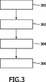
本発明の方法の第1の実施例において、図3を参照して以下の手続きが行われる。 In the first embodiment of the method of the present invention, the following procedure is performed with reference to FIG.
最初に、マルチスライスCTを使用して人間にX線を照射し、人間の気管支樹を表す3Dデータセットがステップ300において既知の方法で作成される。次にステップ302において、この気管支樹は例えばSchlatolter他に記載されるアルゴリズム(Simultaneous Segmentation and Tree Reconstruction of Airways for Virtual Bronchoscopy, SPIE conference on Medical Imaging, Proceedings of SPIE Vol. 4684, pp. 103-113(2002)) に基づいて三次元画像からセグメント化される。
Initially, a multi-slice CT is used to irradiate a person with X-rays and a 3D data set representing the human bronchial tree is created in a known manner at
監視されない気管支樹のセグメント化は気管から始まり、いわゆる前方伝搬方法(front propagation approach)に基づいている。領域成長は、あるハウンズフィールド(Hounsfield)しきい値より下の全てのボクセルを一体にする。成長界面(growth front)が異なるセグメントに分割されるときは、他の領域成長が前記セグメントの各々において始まる。実質組織への"漏れ(leakage)"は、成長界面の有り得る急激な増大を監視することにより検出及び阻止される。この領域成長処理が完了した後、次に気管、気管支及び小さな気道の中心線(骨格線)が抽出され、前記ツリー構造の分岐点を表すリンク付けした図表構造が構築される。 Unsupervised bronchial tree segmentation begins with the trachea and is based on the so-called front propagation approach. Region growth brings together all voxels below a certain Hounsfield threshold. When the growth front is divided into different segments, other region growth begins in each of the segments. “Leakage” into the parenchyma is detected and prevented by monitoring possible rapid growth of the growth interface. After this region growth processing is completed, the trachea, bronchi and small airway centerlines (skeletal lines) are then extracted and a linked diagram structure representing the branch point of the tree structure is constructed.
図3に戻り参照すると、気管支樹構造の平面角視覚化が次にステップ304において決められる。最後にステップ306において、この気管支樹構造の平面視覚化が表示される。
Returning to FIG. 3, planar angle visualization of the bronchial tree structure is then determined at
本発明は、図4に説明されるように、セグメントの閉塞又は交差が起こらず、これらセグメントの階層が明らかであるような気管支樹の二次元の平面マッピングを提案する。本来の幾何学的関係は維持されないが、位相関係は、一般的な路線図におけるように真実である。その上、主セグメントは、冠状投影においてこれらセグメントの本来の幾何学位置のおおよその方向に向け、ここで図4及び図5に説明されるように上部肺葉(42、41)は上に向けられ、下部肺葉(44、43)は下に向けられる。図5は、中間の肺葉45も説明している。提案される平面のマッピングは、気管支樹の概要を単一の二次元図で与え、これは図5に説明されるように解剖学的関係に直観的に類似している。
The present invention proposes a two-dimensional planar mapping of the bronchial tree such that segment occlusion or intersection does not occur and the hierarchy of these segments is clear, as illustrated in FIG. The original geometric relationship is not maintained, but the topological relationship is true as in the general route map. Moreover, the main segments are oriented in the coronal projection in the approximate direction of their original geometric position, where the upper lobes (42, 41) are oriented upwards as described in FIGS. The lower lobes (44, 43) are pointed down. FIG. 5 also illustrates an
この平面マッピング処理の特徴は詳細には説明されない。気管50における左主気管支52及び右主気管支54への主幹分岐(竜骨)は、図4に示されるように平面図の中心に記入されている。この図の他のポイント全ては、これらポイントの図の中心への半径方向距離が気道を介し前記竜骨への中心線距離に比例し、これはCTデータセットの解像度には関係なくミリメートルで測定される。
The features of this planar mapping process will not be described in detail. The main trunk branch (carina) to the left
本実施例において、気管50は、竜骨を表す図の中心に向かい下降し、次に左及び右主気管支が90°で分岐する。この角度が例えば後で詳細に説明される図7に示されるように他の値で固定されることも可能なことは、当業者により理解されるであろう。気道の各分岐において、記入された中心線は、均等な角度ステップ幅で現在の角度方向の左側及び右側に分岐する。この角度ステップ幅は、各分岐後1/2に減少する。これら分岐は、上述した領域成長方法において、成長界面が分解(分裂)した場所として特徴付けられる。
In this example, the
このように、既定のポイントより下のサブツリー(subtree)が他のサブツリーの図表域には入らないことが保証される。 In this way, it is guaranteed that subtrees below the default point will not enter the chart area of other subtrees.
前記マッピングにおける各ポイントは、図の中心に対する角度及び距離により与えられる。この図の中心に対する距離は、竜骨への気管支路距離に比例し、角度は以前の分岐の数により決められる。図におけるセグメントの長さは、前に説明したとおり決められたポイント位置間の接続により与えられる。 Each point in the mapping is given by the angle and distance to the center of the figure. The distance to the center of this figure is proportional to the bronchial tract distance to the keel, and the angle is determined by the number of previous branches. The length of the segment in the figure is given by the connection between the point positions determined as described above.
本実施例において、図におけるセグメントの長さは、その実際の長さの本当の表示ではない。前記セグメントは重複を避けるのに十分離れて広がらなければならないので、これは不可能である。逆に半径方向距離は、竜骨へ戻る気道の長さの本当の表示である。言い換えると、図における正接方向(円周上)距離が前記セグメントを広げるのに使用されるが、半径方向距離は本当である。 In this example, the length of the segment in the figure is not a true indication of its actual length. This is not possible because the segments must be spread far enough to avoid duplication. Conversely, radial distance is a true indication of the length of the airway back to the keel. In other words, the tangential (circumferential) distance in the figure is used to widen the segment, but the radial distance is true.
図10に説明されるような平面マッピングの他の実施例において、図におけるセグメントの長さをセグメントの本当の長さに比例させることも可能である。この代替モードにおいて、図の中心に対するこの図におけるポイントの半径方向距離は竜骨には比例していない。むしろ、それの実際の長さに比例する長さの(竜骨から始まる)各セグメントに対する経路が描かれている。次に、世代iの各分岐において、前記マッピングは、現在の方向から角度±θiだけ新しい方向に分岐し、分岐角は、各世代でθi+1=(1/2)θiで減少するので、閉塞のないマッピングが保証される。 In another embodiment of planar mapping as illustrated in FIG. 10, the length of the segment in the figure can be proportional to the true length of the segment. In this alternative mode, the radial distance of the point in the figure relative to the center of the figure is not proportional to the keel. Rather, a path is drawn for each segment (starting from the keel) of length proportional to its actual length. Next, at each branch of generation i, the mapping branches in a new direction by an angle ± θi from the current direction, and the branching angle decreases at each generation by θi + 1 = (1/2) θi. No mapping is guaranteed.
本当の解剖学的位置に対する図の類似性を改善させるために、図における分岐の方向は、(足から頭の方向に)より高い重心(centroid)を持つ2つのサブツリーの1つが上に向いて曲がっている図における分岐として選択される一方、他の分岐は図の下に向いて曲がっているように制御される。 In order to improve the similarity of the figure to the true anatomical position, the direction of the branch in the figure is that one of the two sub-trees with a higher centroid (from the foot to the head) points upwards While selected as a branch in the bent diagram, the other branches are controlled to be bent down the diagram.
表示される図の色又はグレイスケール値は、図10に説明されるような、解剖学的に区別される葉部(lobe)と主セグメントとを映すように選択される。実際に表示される色又はグレイスケール値は、特徴的な映像をユーザに提供するようにユーザにより選択されることが可能であることは当業者により理解される。 The color or gray scale value of the displayed figure is selected to reflect the anatomically distinct lobes and main segments as illustrated in FIG. It will be appreciated by those skilled in the art that the actual displayed color or gray scale value can be selected by the user to provide the user with a characteristic image.
この図は、図の既定のポイントをマウスでクリックすることがオルトビューワ(orthoviewer)のような他の表示装置を平面マッピングにおける前記クリックポイントにより表される三次元CTのデータセットの場所に直に設置するようにインタラクティブである。この図は、図の既定のポイントをマウスでクリックすることがこのポイントから気管への気道の中心線路を選択し、この線路に沿って他の定量的情報、例えば内腔の直径、気管支壁の厚さ等を表示するようにインタラクティブである。この図は、ある図領域にわたるマウスの移動は、高次の前記ツリー世代が識別可能になるようにこの領域を拡大するようにインタラクティブである。 This figure shows that clicking on a predetermined point in the figure with a mouse directly brings another display device such as an orthoviewer to the location of the 3D CT dataset represented by the click point in planar mapping. Interactive to install. This figure shows that clicking on a predefined point in the figure with the mouse selects the central track of the airway from this point to the trachea, along with other quantitative information such as lumen diameter, bronchial wall It is interactive to display thickness etc. This figure shows that mouse movement across a diagram region is interactive to expand this region so that higher tree generations can be identified.
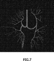
他の特徴は、竜骨から規定の距離にある前記ツリーにおけるポイントの全てに対し、垂直方向に再フォーマットされた画像が図の対応する位置に示され、図6の画像により説明されるように、スライダを動かすことが前記規定の竜骨への距離を変更することを可能にするようにユーザがGUIのスライダを移動させることが可能である。この竜骨への距離に対する気道内腔直径を示す平面マッピングの代替表示が図7に示される。 Another feature is that, for all of the points in the tree that are at a specified distance from the keel, vertically reformatted images are shown in corresponding positions in the figure, as illustrated by the image in FIG. The user can move the slider of the GUI so that moving the slider allows the distance to the prescribed keel to be changed. An alternative representation of planar mapping showing airway lumen diameter versus distance to the keel is shown in FIG.
図の各ポイントにおける線の太さは、気管支樹の対応するポイントでの測定される気道内腔直径に比例するように描かれる。異なる線の太さは図7に説明される。 The line thickness at each point in the figure is drawn to be proportional to the measured airway lumen diameter at the corresponding point in the bronchial tree. The different line thicknesses are illustrated in FIG.
円滑な角度補間は、図7に説明されるようなより有機的な外観を与えるために使用される。分岐は図4及び図5における位置と同じ位置にあり、その位置は以前の分岐の数及び竜骨までの長さにより規定されるが、これら分岐点間において、中心線のポイントは、その角度及び半径方向距離(ρ及びφ座標)に関し線形に補間される。 Smooth angular interpolation is used to give a more organic appearance as illustrated in FIG. The branches are in the same positions as in FIGS. 4 and 5, the position being defined by the number of previous branches and the length to the keel, but between these branches, the centerline point is the angle and Linear interpolation is performed with respect to the radial distance (ρ and φ coordinates).
図の各ポイントにおける気管支壁の厚さは、気管支樹において対応するポイントにおける測定される壁の厚さに比例するように図が描かれる。 The figure is drawn such that the bronchial wall thickness at each point in the figure is proportional to the measured wall thickness at the corresponding point in the bronchial tree.
気管支の内腔直径及び壁の厚さに関する異常が自動的に検出され、図のそれぞれの位置にマーカ又は色分け(color coding)により指し示される。さらに、他の画像処理モジュールは、気管支樹の各ポイントにおいて付随する動脈を見つけることができる。この付随する動脈の直径は自動的に測定されることができる。このとき、(重要な臨床パラメタである)気管支の直径と動脈の直径との比は平面マッピングの各ポイントに色分けされることができる。 Abnormalities related to bronchial lumen diameter and wall thickness are automatically detected and indicated by markers or color coding at each location in the figure. In addition, other image processing modules can find associated arteries at each point in the bronchial tree. This accompanying arterial diameter can be automatically measured. At this time, the ratio of the diameter of the bronchus (which is an important clinical parameter) to the diameter of the artery can be color-coded to each point of the planar mapping.
この平面マッピングの他の応用は、セグメント化された肺動脈血管樹をマッピングすることであり、グラフの各ポイントにおいて血管の直径又は何らかの可能な検出される異常を表示することである。例えば、グラフの各ポイントにおいて、この血管部におけるCTハウンズフィールド(CT-Hounsfileld)の最小投影がレンダリングされるので、(血塊により生じ、場合によっては肺塞栓症を示す)陰影欠損(filling defect)が一目で検出されることができる。 Another application of this planar mapping is to map a segmented pulmonary artery vascular tree, displaying the diameter of the vessel or any possible detected anomalies at each point of the graph. For example, at each point in the graph, a minimal projection of CT-Hounsfileld at this vessel is rendered, so there is a filling defect (caused by blood clots and possibly pulmonary embolism). Can be detected at a glance.
図8による本発明の他の実施例において、コンピュータ読み取り可能媒体が概略的に説明されている。コンピュータ読み取り可能媒体100は、コンピュータ113により処理するための、3D医療画像112から解剖学的ツリーの平面角視覚化を自動抽出するコンピュータプログラム110を取り込んでいる。このコンピュータプログラムは、身体の少なくとも一部の三次元画像セットから解剖学的ツリー構造をセグメント化するコードセグメント114、この解剖学的ツリー構造の平面角視覚化を決めるためのコードセグメント115、及びこの解剖学的ツリー構造の平面角視覚化を表示するためのコードセグメント116を有する。
In another embodiment of the invention according to FIG. 8, a computer readable medium is schematically described. The computer
図9は、本発明による他の実施例に従う例示的な医療画像ワークステーション119を説明している。この医療ワークステーションは、本発明の方法を実施するために配され、3D医療画像を入力及び処理するように構成される。好ましくは、このワークステーションは、本発明による方法を実行するために上述したプログラムのコードセグメントを実行するように配される。本実施例によれば、医療ワークステーション119は、3D医療画像から解剖学的ツリーの平面角視覚化を自動抽出するために構成され、身体の少なくとも一部の三次元画像セットから解剖学的ツリー構造をセグメント化するためのセグメント化手段120、解剖学的ツリー構造の平面視覚化を決めるための決定手段121、及び前記解剖学的ツリー構造の平面角視覚化を表示するための表示手段122を有する。上記手段120−122は好ましくは、適当なやり方で互いに動作可能な状態で接続される電子部品である。例えばディスプレイ又はポインタ作動装置のような医療ワークステーションの他の部品は詳細には説明又は論じない。
FIG. 9 illustrates an exemplary
本発明は、ハードウェア、ソフトウェア、ファームウェア又はこれら何れかの組み合わせを含む何らかの適当な形式で実施される。しかしながら好ましくは、本発明は1つ以上のデータプロセッサ及び/又はデジタル信号プロセッサ上で実行するコンピュータソフトウェアとして実施される。本発明の実施例の要素及び部品は、何らかの適当なやり方で物理的、機能的及び論理的に実施されてもよい。実際は、機能が単一ユニット、複数のユニット又は他の機能ユニットの一部として実施されてもよい。本発明は単一ユニットで実施されてもよいし、又は異なるユニット及びプロセッサ間に物理的及び機能的に分散されてもよい。 The invention is implemented in any suitable form including hardware, software, firmware or any combination of these. Preferably, however, the invention is implemented as computer software running on one or more data processors and / or digital signal processors. The elements and components of an embodiment of the invention may be physically, functionally and logically implemented in any suitable way. In practice, functions may be implemented as a single unit, multiple units, or part of another functional unit. The invention may be implemented in a single unit or may be physically and functionally distributed between different units and processors.
本発明が特定の実施例を参照して上述したとしても、ここで述べた特定の形式に限定されることを意味していない。むしろ、本発明は付随する特許請求の範囲によってのみ限定され、例えば上述した構造とは異なる解剖学的ツリー構造のような上記以外の他の実施例は、添付の特許請求の範囲内において同様に可能である。 Although the present invention has been described above with reference to specific embodiments, it is not meant to be limited to the specific form set forth herein. Rather, the invention is limited only by the accompanying claims and, other embodiments such as, for example, anatomical tree structures different from those described above, are equally within the scope of the appended claims. Is possible.
請求項において、"有する/持つ"の用語は他の要素又はステップの存在を排除するものではない。さらに個々に挙げられたとしても、複数の手段、要素又は方法のステップが例えば単一ユニット又はプロセッサにより実施されてもよい。加えて、個々の特徴が別々の請求項に含まれていたとしても、これら特徴が場合によって有利に組み合わされてもよく、別々の請求項に含まれることが特徴の組み合わせは不可能である及び/又は有利ではないことを意味しているのではない。加えて、単数での表示は複数あることを排除するものではない。"1つ"、"第1"、"第2"等は複数あることを排除するものではない。請求項における参照符号は単に明瞭な例として設けられ、決して特許請求の範囲を限定するとは解釈しない。 In the claims, the term “comprising / having” does not exclude the presence of other elements or steps. Even more individually, a plurality of means, elements or method steps may be implemented by eg a single unit or processor. In addition, even if individual features are included in separate claims, these features may be advantageously combined in some cases, and combinations of features are not possible if included in separate claims and Does not mean that it is not advantageous. In addition, the singular display does not exclude a plurality. It is not excluded that there are a plurality of “one”, “first”, “second” and the like. Reference signs in the claims are provided merely as a clarifying example and shall not be construed as limiting the scope of the claims in any way.
Claims (11)
−身体の少なくとも一部の三次元画像セットから前記解剖学的ツリー構造をセグメント化するためのセグメント化手段、及び
−前記解剖学的ツリー構造の平面角視覚化を決めるための決定手段
を有するシステムであって、
世代iの各分岐において、前記解剖学的ツリー構造の前記平面角視覚化は、現在の方向から分岐角±θiだけ2つの新しい方向に分岐し、前記分岐角は各世代でθi+1=(1/2)θiで減少することを特徴とする、システム。In a system for visualizing anatomical tree structures,
A segmentation means for segmenting the anatomical tree structure from a three-dimensional image set of at least a part of the body, and a system comprising a determination means for determining a planar angle visualization of the anatomical tree structure Because
At each branch of generation i, the planar angle visualization of the anatomical tree structure branches in two new directions from the current direction by a branch angle ± θ i , where the branch angle is θ i + 1 = (1/2) A system characterized by decreasing at θ i .
−身体の少なくとも一部の三次元画像セットから前記解剖学的ツリー構造をセグメント化するためのコードセグメント、及び
−前記解剖学的ツリー構造の平面角視覚化を決めるためのコードセグメントを有するコンピュータプログラムを取り込んでいるコンピュータ読み取り可能媒体であって、
世代iの各分岐において、前記解剖学的ツリー構造の前記平面角視覚化は、現在の方向から分岐角±θiだけ2つの新しい方向に分岐し、前記分岐角は各世代でθi+1=(1/2)θiで減少することを特徴とする、コンピュータ読み取り可能媒体。In a computer readable medium incorporating a computer program for automatically extracting an anatomical tree structure for processing by a computer,
A computer program comprising: a code segment for segmenting the anatomical tree structure from a three-dimensional image set of at least a part of the body; and a code segment for determining a planar angle visualization of the anatomical tree structure A computer readable medium incorporating
At each branch of generation i, the planar angle visualization of the anatomical tree structure branches in two new directions from the current direction by a branch angle ± θ i , where the branch angle is θ i + 1 = (1/2) A computer-readable medium, characterized by decreasing by θ i .
Applications Claiming Priority (5)
| Application Number | Priority Date | Filing Date | Title |
|---|---|---|---|
| EP04106013.8 | 2004-11-23 | ||
| EP04106013 | 2004-11-23 | ||
| EP05102793.6 | 2005-04-08 | ||
| EP05102793 | 2005-04-08 | ||
| PCT/IB2005/053829 WO2006056923A1 (en) | 2004-11-23 | 2005-11-21 | Planar angular visualization of the bronchial tree |
Publications (3)
| Publication Number | Publication Date |
|---|---|
| JP2008520319A JP2008520319A (en) | 2008-06-19 |
| JP2008520319A5 JP2008520319A5 (en) | 2009-01-22 |
| JP4871292B2 true JP4871292B2 (en) | 2012-02-08 |
Family
ID=35814189
Family Applications (1)
| Application Number | Title | Priority Date | Filing Date |
|---|---|---|---|
| JP2007542441A Active JP4871292B2 (en) | 2004-11-23 | 2005-11-21 | System for visualizing anatomical tree structures |
Country Status (5)
| Country | Link |
|---|---|
| US (1) | US8045769B2 (en) |
| EP (1) | EP1817742B1 (en) |
| JP (1) | JP4871292B2 (en) |
| CN (1) | CN101065771B (en) |
| WO (1) | WO2006056923A1 (en) |
Families Citing this family (17)
| Publication number | Priority date | Publication date | Assignee | Title |
|---|---|---|---|---|
| DE602006008113D1 (en) * | 2005-02-11 | 2009-09-10 | Philips Intellectual Property | METHOD FOR THE AUTOMATIC EXTRACTION OF THE LUNG ARTERY CONSTANCE FROM MEDICAL 3D IMAGES |
| EP2279491B1 (en) | 2008-04-18 | 2012-02-01 | Koninklijke Philips Electronics N.V. | Segmenting pulmonary arteries |
| AU2011210257B2 (en) * | 2010-02-01 | 2013-12-19 | Covidien Lp | Region-growing algorithm |
| JP5584006B2 (en) * | 2010-03-31 | 2014-09-03 | 富士フイルム株式会社 | Projection image generation apparatus, projection image generation program, and projection image generation method |
| DE102012204063B4 (en) * | 2012-03-15 | 2021-02-18 | Siemens Healthcare Gmbh | Generation of visualization command data |
| JP5833994B2 (en) * | 2012-09-20 | 2015-12-16 | 富士フイルム株式会社 | Image processing apparatus and method, and program |
| CN104036484B (en) | 2013-03-06 | 2017-08-08 | 东芝医疗系统株式会社 | Image segmenting device, image partition method and medical image equipment |
| JP6080267B2 (en) * | 2014-09-12 | 2017-02-15 | 富士フイルム株式会社 | Three-dimensional object division output device and its application |
| US9901406B2 (en) | 2014-10-02 | 2018-02-27 | Inneroptic Technology, Inc. | Affected region display associated with a medical device |
| US10188467B2 (en) | 2014-12-12 | 2019-01-29 | Inneroptic Technology, Inc. | Surgical guidance intersection display |
| US9949700B2 (en) * | 2015-07-22 | 2018-04-24 | Inneroptic Technology, Inc. | Medical device approaches |
| CN105224759B (en) * | 2015-10-13 | 2018-03-20 | 张帆 | A kind of human anatomic structure model, implant quick molding method |
| AU2017213639B2 (en) * | 2016-02-05 | 2021-03-11 | Pulmonx Corporation | Methods, systems, and devices for analyzing lung imaging data |
| CN110246126A (en) * | 2019-06-14 | 2019-09-17 | 吉林大学第一医院 | A method of extracting terminal bronchi tree from lung CT image |
| US11875459B2 (en) | 2020-04-07 | 2024-01-16 | Vida Diagnostics, Inc. | Subject specific coordinatization and virtual navigation systems and methods |
| CN111861988A (en) * | 2020-06-09 | 2020-10-30 | 深圳市旭东数字医学影像技术有限公司 | Method and system for automatic and semi-automatic lung lobular segmentation based on bronchus |
| US20220249014A1 (en) * | 2021-02-05 | 2022-08-11 | Siemens Healthcare Gmbh | Intuitive display for rotator cuff tear diagnostics |
Citations (4)
| Publication number | Priority date | Publication date | Assignee | Title |
|---|---|---|---|---|
| JPH04289803A (en) * | 1991-03-18 | 1992-10-14 | Nippon Sheet Glass Co Ltd | Multiple branch optical circuit |
| JPH0696223A (en) * | 1992-09-16 | 1994-04-08 | Matsushita Electric Ind Co Ltd | Tree structure drawing plotter |
| JP2004113537A (en) * | 2002-09-27 | 2004-04-15 | Ziosoft Inc | Method, equipment and program for cpr image display processing of ramification field |
| JP2005537532A (en) * | 2002-05-07 | 2005-12-08 | インターナショナル・ビジネス・マシーンズ・コーポレーション | Comprehensive development tool for building natural language understanding applications |
Family Cites Families (6)
| Publication number | Priority date | Publication date | Assignee | Title |
|---|---|---|---|---|
| JPS575109A (en) * | 1980-06-10 | 1982-01-11 | Fanuc Ltd | Curved surface forming method |
| FR2708166A1 (en) * | 1993-07-22 | 1995-01-27 | Philips Laboratoire Electroniq | A method of processing digitized images for the automatic detection of stenoses. |
| US6246784B1 (en) * | 1997-08-19 | 2001-06-12 | The United States Of America As Represented By The Department Of Health And Human Services | Method for segmenting medical images and detecting surface anomalies in anatomical structures |
| US6690816B2 (en) * | 2000-04-07 | 2004-02-10 | The University Of North Carolina At Chapel Hill | Systems and methods for tubular object processing |
| GB2395880B (en) | 2002-11-27 | 2005-02-02 | Voxar Ltd | Curved multi-planar reformatting of three-dimensional volume data sets |
| US7469073B2 (en) * | 2004-05-24 | 2008-12-23 | Siemens Medical Solutions Usa, Inc. | Image-based method for detection and removal of small fragments in segmented three-dimensional volumes |
-
2005
- 2005-11-21 JP JP2007542441A patent/JP4871292B2/en active Active
- 2005-11-21 CN CN2005800401985A patent/CN101065771B/en active Active
- 2005-11-21 US US11/719,549 patent/US8045769B2/en active Active
- 2005-11-21 WO PCT/IB2005/053829 patent/WO2006056923A1/en active Application Filing
- 2005-11-21 EP EP05806939.4A patent/EP1817742B1/en active Active
Patent Citations (4)
| Publication number | Priority date | Publication date | Assignee | Title |
|---|---|---|---|---|
| JPH04289803A (en) * | 1991-03-18 | 1992-10-14 | Nippon Sheet Glass Co Ltd | Multiple branch optical circuit |
| JPH0696223A (en) * | 1992-09-16 | 1994-04-08 | Matsushita Electric Ind Co Ltd | Tree structure drawing plotter |
| JP2005537532A (en) * | 2002-05-07 | 2005-12-08 | インターナショナル・ビジネス・マシーンズ・コーポレーション | Comprehensive development tool for building natural language understanding applications |
| JP2004113537A (en) * | 2002-09-27 | 2004-04-15 | Ziosoft Inc | Method, equipment and program for cpr image display processing of ramification field |
Also Published As
| Publication number | Publication date |
|---|---|
| EP1817742A1 (en) | 2007-08-15 |
| WO2006056923A1 (en) | 2006-06-01 |
| EP1817742B1 (en) | 2018-01-10 |
| US20090148008A1 (en) | 2009-06-11 |
| CN101065771B (en) | 2011-05-18 |
| US8045769B2 (en) | 2011-10-25 |
| CN101065771A (en) | 2007-10-31 |
| JP2008520319A (en) | 2008-06-19 |
Similar Documents
| Publication | Publication Date | Title |
|---|---|---|
| JP4871292B2 (en) | System for visualizing anatomical tree structures | |
| JP6877868B2 (en) | Image processing equipment, image processing method and image processing program | |
| US7599535B2 (en) | System and method for tree-model visualization for pulmonary embolism detection | |
| JP6080249B2 (en) | Three-dimensional image display apparatus and method, and program | |
| US7020510B2 (en) | Optimal view map V.0.01 | |
| US20230346236A1 (en) | System for vascular assessment | |
| JP6080248B2 (en) | Three-dimensional image display apparatus and method, and program | |
| US10039510B2 (en) | Visualizing different types of airway wall abnormalities | |
| US20070276214A1 (en) | Systems and Methods for Automated Segmentation, Visualization and Analysis of Medical Images | |
| JP2006051359A (en) | Method and apparatus for medical intervention procedure planning and location and navigation of an intervention tool | |
| Bullitt et al. | Volume rendering of segmented image objects | |
| US20110293150A1 (en) | Iterative vascular reconstruction by seed point segmentation | |
| Ropinski et al. | Multimodal vessel visualization of mouse aorta PET/CT scans | |
| He et al. | Medial axis reformation: a new visualization method for CT angiography | |
| Wink et al. | Intra-procedural coronary intervention planning using hybrid 3-dimensional reconstruction techniques1 | |
| CN112884879B (en) | Method for providing a two-dimensional unfolded image of at least one tubular structure | |
| Andronikou et al. | Technical developments in postprocessing of paediatric airway imaging | |
| WO2010001327A1 (en) | Processing anatomy and associated quantitative analysis data of tissue | |
| Muhammad Abdullah Adli | Investigation of in vivo cardiac chambers composite rendering/Muhammad Abdullah Adli Ahmad Kamal | |
| Kamal | Investigation of in Vivo Cardiac Chambers Composite Rendering | |
| Chen et al. | Bolus tracking by cone-beam reconstruction and reprojection | |
| Krishnamoorthy et al. | System for segmentation and selective visualization of the coronary artery tree for evaluation of stenosis, soft plaque and calcification in cardiac CTA |
Legal Events
| Date | Code | Title | Description |
|---|---|---|---|
| A521 | Request for written amendment filed |
Free format text: JAPANESE INTERMEDIATE CODE: A523 Effective date: 20081120 |
|
| A621 | Written request for application examination |
Free format text: JAPANESE INTERMEDIATE CODE: A621 Effective date: 20081120 |
|
| A977 | Report on retrieval |
Free format text: JAPANESE INTERMEDIATE CODE: A971007 Effective date: 20110414 |
|
| A131 | Notification of reasons for refusal |
Free format text: JAPANESE INTERMEDIATE CODE: A131 Effective date: 20110421 |
|
| A521 | Request for written amendment filed |
Free format text: JAPANESE INTERMEDIATE CODE: A523 Effective date: 20110601 |
|
| A131 | Notification of reasons for refusal |
Free format text: JAPANESE INTERMEDIATE CODE: A131 Effective date: 20110623 |
|
| A521 | Request for written amendment filed |
Free format text: JAPANESE INTERMEDIATE CODE: A523 Effective date: 20110711 |
|
| A131 | Notification of reasons for refusal |
Free format text: JAPANESE INTERMEDIATE CODE: A131 Effective date: 20110804 |
|
| A521 | Request for written amendment filed |
Free format text: JAPANESE INTERMEDIATE CODE: A523 Effective date: 20110822 |
|
| TRDD | Decision of grant or rejection written | ||
| A01 | Written decision to grant a patent or to grant a registration (utility model) |
Free format text: JAPANESE INTERMEDIATE CODE: A01 Effective date: 20111025 |
|
| A01 | Written decision to grant a patent or to grant a registration (utility model) |
Free format text: JAPANESE INTERMEDIATE CODE: A01 |
|
| A61 | First payment of annual fees (during grant procedure) |
Free format text: JAPANESE INTERMEDIATE CODE: A61 Effective date: 20111118 |
|
| R150 | Certificate of patent or registration of utility model |
Ref document number: 4871292 Country of ref document: JP Free format text: JAPANESE INTERMEDIATE CODE: R150 Free format text: JAPANESE INTERMEDIATE CODE: R150 |
|
| FPAY | Renewal fee payment (event date is renewal date of database) |
Free format text: PAYMENT UNTIL: 20141125 Year of fee payment: 3 |
|
| R250 | Receipt of annual fees |
Free format text: JAPANESE INTERMEDIATE CODE: R250 |
|
| R250 | Receipt of annual fees |
Free format text: JAPANESE INTERMEDIATE CODE: R250 |
|
| R250 | Receipt of annual fees |
Free format text: JAPANESE INTERMEDIATE CODE: R250 |
|
| R250 | Receipt of annual fees |
Free format text: JAPANESE INTERMEDIATE CODE: R250 |
|
| R250 | Receipt of annual fees |
Free format text: JAPANESE INTERMEDIATE CODE: R250 |
|
| R250 | Receipt of annual fees |
Free format text: JAPANESE INTERMEDIATE CODE: R250 |
|
| R250 | Receipt of annual fees |
Free format text: JAPANESE INTERMEDIATE CODE: R250 |
|
| R250 | Receipt of annual fees |
Free format text: JAPANESE INTERMEDIATE CODE: R250 |
|
| R250 | Receipt of annual fees |
Free format text: JAPANESE INTERMEDIATE CODE: R250 |