JP4869100B2 - Communication method and image communication apparatus - Google Patents
Communication method and image communication apparatus Download PDFInfo
- Publication number
- JP4869100B2 JP4869100B2 JP2007036806A JP2007036806A JP4869100B2 JP 4869100 B2 JP4869100 B2 JP 4869100B2 JP 2007036806 A JP2007036806 A JP 2007036806A JP 2007036806 A JP2007036806 A JP 2007036806A JP 4869100 B2 JP4869100 B2 JP 4869100B2
- Authority
- JP
- Japan
- Prior art keywords
- message
- mfp
- communication
- call control
- transmitter
- Prior art date
- Legal status (The legal status is an assumption and is not a legal conclusion. Google has not performed a legal analysis and makes no representation as to the accuracy of the status listed.)
- Expired - Fee Related
Links
Images


Classifications
-
- H—ELECTRICITY
- H04—ELECTRIC COMMUNICATION TECHNIQUE
- H04L—TRANSMISSION OF DIGITAL INFORMATION, e.g. TELEGRAPHIC COMMUNICATION
- H04L65/00—Network arrangements, protocols or services for supporting real-time applications in data packet communication
- H04L65/1066—Session management
- H04L65/1069—Session establishment or de-establishment
-
- H—ELECTRICITY
- H04—ELECTRIC COMMUNICATION TECHNIQUE
- H04L—TRANSMISSION OF DIGITAL INFORMATION, e.g. TELEGRAPHIC COMMUNICATION
- H04L65/00—Network arrangements, protocols or services for supporting real-time applications in data packet communication
- H04L65/1066—Session management
- H04L65/1101—Session protocols
- H04L65/1104—Session initiation protocol [SIP]
Description
本発明は通信方法及び画像通信装置に関する。特に、送信機でスキャナから読み取った画像を通信回線上に送信し、受信機側で受信した画像データをプリンタで印刷する画像通信システムにおける通信方法及び画像通信装置に関する。 The present invention relates to a communication method and an image communication apparatus. In particular, the present invention relates to a communication method and an image communication apparatus in an image communication system in which an image read from a scanner by a transmitter is transmitted on a communication line and image data received by the receiver is printed by a printer.
昨今H.323、SIP等の呼接続プロトコルを用いたIP電話が普及しはじめ、ITU-T勧告T.38等の勧告に従ったIPファクシミリも発売されている。 Recently, IP telephones using call connection protocols such as H.323 and SIP have begun to spread, and IP facsimiles complying with recommendations such as ITU-T recommendation T.38 have been released.
図9は、SIPを用いたIP電話の接続形態の一例である。 FIG. 9 is an example of a connection form of an IP phone using SIP.
送信機からINVITEリクエスト900が送信機側SIPサーバに送られる。すると、送信機側のSIPサーバは、受信機側SIPサーバにINVITEリクエストを送り、送信機に対してメッセージを受理し試行中であることを示すTrying信号メッセージ901を返答する。INVITEリクエスト902を受信した受信機側のSIPサーバは、受信機にINVITEリクエスト904を送信し、送信機側のSIPサーバにTrying信号メッセージ903を返答する。
An INVITE
INVITEリクエスト904を受信した受信機は、呼び出し音を鳴らし、呼び出し中であることを示すRinging信号905を受信機側のSIPサーバに送信する。このRinging信号は、Ringing信号のメッセージ906、907で送信機に伝えられる。
The receiver that has received the
受信機側のユーザが電話に出ると、OK信号メッセージ908が受信機から受信側のSIPサーバに送られ、OK信号メッセージ909、910にて送信機に伝えられる。OK信号メッセージ910を受信した送信機は、ACK信号メッセージ911を受信機に直接送信し、呼制御プロトコルのシーケンスは終了する。
When the user on the receiver side answers the telephone, an
呼制御シーケンス終了後はメディアセッションに移行し、音声データをPCM等により符号化したデータ912〜915が通信される。会話終了後に受話器が置かれると、送信機から受信機にBYE信号916が送られ、その応答信号としてOK信号917が受信機から送信機に返答され、全ての通信は終了する。
After the end of the call control sequence, a transition is made to a media session, and
図10は、図9に示すINVITEリクエスト900の内容の一例である。
FIG. 10 shows an example of the contents of the
950には、メッセージがINVITEリクエストであることが記述される。Viaヘッダフィールド951は、トランザクションのために使用されるトランスポートを示す。Max-Forwardsフィールド952は、受信機に到達するまでの通過することができるホップの数を制限するためのフィールドである。
950 describes that the message is an INVITE request. Via
953は受信者がBobであることを示し、954にて送信者がAliceであることを示している。Call-IDヘッダフィールド955は、連続するメッセージをグループ化するための識別子であり、全てのリクエストとその応答は同一のCall-IDが使われる。
953 indicates that the receiver is Bob, and 954 indicates that the sender is Alice. The Call-
CSeq956は、トランザクションを識別し順番付けするための番号であり、Contactヘッダ957は、コンタクトするために使用できるSIP URIを提供する。Content-Type958は、メッセージのメディアタイプを示し、Content-Length959は送られたメッセージのサイズを示す。
CSeq 956 is a number for identifying and ordering transactions, and the
接続している呼の接続数を管理する特許文献としては、特許文献1があげられる。特許文献1では、VoIPゲートウェイ装置において、割当てられた少なくとも1つの電話番号について、現在接続している呼の同時接続数を管理し、同時接続許容数より少ない電話番号を選択し、選択した電話番号の呼制御することが記載されている。
ところで、T.30に従ったG3ファクシミリでは同時に複数の受信を行うために電話回線を複数所有しなければならなかったが、IPファクシミリでは広帯域の1つのNetwork回線であるため同時に複数接続可能である。 By the way, the G3 facsimile according to T.30 had to own multiple telephone lines in order to simultaneously receive a plurality of signals. However, since the IP facsimile is a single broadband network line, a plurality of lines can be connected simultaneously. .
しかしながら、SIPプロトコルは、接続したクライアントとサーバのネットワークコネクションを維持しないので、接続した相手以外のコマンドについても並列して処理する必要がある。すなわち、各メッセージの通信が終了すると接続を打ち切り、コマンドとコマンドの間に他の機器のメッセージが混じるように動作する。このために、複数の送信機が同時に呼接続を行うと、受信機は接続しているJOBのCall-ID毎に状態管理を実行しなければならない。 However, since the SIP protocol does not maintain the network connection between the connected client and server, it is necessary to process commands other than the connected partner in parallel. That is, when the communication of each message is completed, the connection is terminated, and the operation is performed so that messages of other devices are mixed between the commands. For this reason, when a plurality of transmitters make a call connection at the same time, the receiver must execute state management for each Call-ID of the connected job.
上記状態管理を行うプログラムは、受信機の状態を監視し、受信機の状態と該状態時に受け付けることが可能なコマンドとを認識し、可能なコマンド以外のコマンドを受信した場合は定められたエラーコードを返答するように動作する。更に、受け付けることが可能なコマンドを受信した場合は、各コマンドに対応する内部プログラムを実行し、受信機の状態を別の状態に遷移させる等の複雑な処理を行う。このプログラムを実行すると、プログラムで必要となる資源が使われる。 The status management program monitors the status of the receiver, recognizes the status of the receiver and the commands that can be accepted in that status, and if a command other than a possible command is received, the specified error Operates to return a code. Further, when a command that can be accepted is received, an internal program corresponding to each command is executed, and complicated processing such as changing the state of the receiver to another state is performed. When this program is executed, resources required by the program are used.
同時に複数の接続を許可すると、すでに接続済みの通信により資源が使われてしまい、後から接続された通信のためにはプログラムを動かすことができず、使われている資源に応じて動作方法を変更しなければならない。接続されるJOBの数は受信機側では規定することはできない。そのため、膨大な数の複数のJOBを同時並行的に処理することとなり、プログラムサイズの増大、使用メモリの増大、プログラム開発費の増大につながり、安価なシステムでの運用は困難であった。 If multiple connections are allowed at the same time, resources will be used by the already connected communication, and the program cannot be moved for later connected communication. Must be changed. The number of connected jobs cannot be specified on the receiver side. Therefore, an enormous number of multiple jobs are processed in parallel, leading to an increase in program size, an increase in memory usage, and an increase in program development costs, making it difficult to operate on an inexpensive system.
本発明は、上記問題を鑑み、その目的は呼制御プロトコルを用いて画像データの通信を行う画像通信装置において、安価に実運用上は問題を発生させることなく並行して複数の装置と通信が可能な通信方法及び画像通信装置を提供することにある。 In view of the above problems, an object of the present invention is to provide an image communication apparatus that communicates image data using a call control protocol, and can communicate with a plurality of apparatuses in parallel at low cost without causing problems in actual operation. An object of the present invention is to provide a communication method and an image communication apparatus that can be used.
かかる課題を解決するために、本発明の画像通信装置は、呼制御プロトコルを用いて画像データの通信を行う画像通信装置であって、送信装置からのメッセージを受信するメッセージ受信手段と、前記メッセージ受信手段が受信したメッセージに対する応答を前記送信装置に送信するメッセージ送信手段と、第1の送信装置からの呼制御リクエスト・メッセージを受信して前記第1の送信装置との呼制御を実行している途中に、第2の送信装置からの呼制御リクエスト・メッセージを受信した場合、前記第2の送信装置からの呼制御リクエスト・メッセージに対する応答を、前記第1の送信装置との呼制御が終了した後に送信し、前記第1の送信装置との画像データの通信と並行して前記第2の送信装置との呼制御を実行するよう制御する通信制御手段と、を備えることを特徴とする。
In order to solve this problem, an image communication apparatus according to the present invention is an image communication apparatus that performs communication of image data using a call control protocol, and a message receiving unit that receives a message from a transmission apparatus; A message transmitting means for transmitting a response to the message received by the receiving means to the transmitting apparatus; and a call control request message from the first transmitting apparatus is received to perform call control with the first transmitting apparatus. If a call control request message from the second transmitter is received during the call, a response to the call control request message from the second transmitter is completed, and the call control with the first transmitter is completed. passing the control to be sent to after, performing the communication of image data between parallel call control with the second transmission device between the first transmission device Characterized in that it comprises a control means.
また、呼制御プロトコルを用いて画像データの通信を行う画像通信装置であって、送信装置からのメッセージを受信するメッセージ受信手段と、前記メッセージ受信手段が受信したメッセージに対する応答を前記送信装置に送信するメッセージ送信手段と、第1の送信装置からの呼制御リクエスト・メッセージを受信して前記第1の送信装置との呼制御を実行している途中に、第2の送信装置からの呼制御リクエスト・メッセージを受信した場合は、前記第2の送信装置からの呼制御リクエスト・メッセージに対する応答として、他の装置と通信中であることを示すメッセージを前記第2の送信装置に送信し、前記第1の送信装置との呼制御が終了し、前記第1の送信装置との画像データの通信を開始した後に、前記第2の送信装置からの呼制御リクエスト・メッセージを受信した場合は、前記第1の送信装置との画像データの通信と並行して前記第2の送信装置との呼制御を実行するよう制御する通信制御手段と、を備えることを特徴とする。
An image communication apparatus that communicates image data using a call control protocol, wherein a message reception unit that receives a message from a transmission device and a response to the message received by the message reception unit is transmitted to the transmission device. A call control request from the second transmitter while receiving a call control request message from the first transmitter and executing the call control with the first transmitter. when receiving a message, and sends the response to the call control request message from the second transmitter, the second transmitter device a message indicating that it is communicating with another device, the first After the call control with the first transmission device is finished and the image data communication with the first transmission device is started, the call from the second transmission device is started. When receiving the control request message, it and a communication control means for controlling to execute a call control between the first transmission device and the image data of the parallel with the communication the second transmission device It is characterized by.
また、本発明の通信方法は、呼制御プロトコルを用いて画像データの通信を行う画像通信装置の通信方法であって、メッセージ受信手段が、送信装置からのメッセージを受信するメッセージ受信工程と、メッセージ送信手段が、前記メッセージ受信工程で受信したメッセージに対する応答を前記送信装置に送信するメッセージ送信工程と、通信制御手段が、第1の送信装置からの呼制御リクエスト・メッセージを受信して前記第1の送信装置との呼制御を実行している途中に、第2の送信装置からの呼制御リクエスト・メッセージを受信した場合、前記第2の送信装置からの呼制御リクエスト・メッセージに対する応答を、前記第1の送信装置との呼制御が終了した後に送信し、前記第1の送信装置との画像データの通信と並行して前記第2の送信装置との呼制御を実行するよう制御する通信制御工程と、を備えることを特徴とする。
The communication method of the present invention is a communication method for an image communication apparatus that performs image data communication using a call control protocol, wherein a message receiving unit receives a message from a transmitting apparatus, and a message A message transmission step in which a transmission means transmits a response to the message received in the message reception step to the transmission device; and a communication control means receives the call control request message from the first transmission device and receives the first call control request message. When a call control request message is received from the second transmitter while the call control with the transmitter is performed, a response to the call control request message from the second transmitter is transmitted since the call control of the first transmission device is finished, the first transmitter device the image data in parallel with the communication the second and Characterized in that it comprises a communication control step of controlling to execute a call control with the transmitting device.
また、呼制御プロトコルを用いて画像データの通信を行う画像通信装置の通信方法であって、メッセージ受信手段が、送信装置からのメッセージを受信するメッセージ受信工程と、メッセージ送信手段が、前記メッセージ受信工程で受信したメッセージに対する応答を前記送信装置に送信するメッセージ送信工程と、通信制御手段が、第1の送信装置からの呼制御リクエスト・メッセージを受信して前記第1の送信装置との呼制御を実行している途中に、第2の送信装置からの呼制御リクエスト・メッセージを受信した場合は、前記第2の送信装置からの呼制御リクエスト・メッセージに対する応答として、他の装置と通信中であることを示すメッセージを前記第2の送信装置に送信し、前記第1の送信装置との呼制御が終了し、前記第1の送信装置との画像データの通信を開始した後に、前記第2の送信装置からの呼制御リクエスト・メッセージを受信した場合は、前記第1の送信装置との画像データの通信と並行して前記第2の送信装置との呼制御を実行するよう制御する通信制御工程と、を備えることを特徴とする。 Also, there is provided a communication method for an image communication apparatus that performs image data communication using a call control protocol, in which a message receiving unit receives a message from a transmitting apparatus, and a message transmitting unit includes the message receiving unit. A message transmission step of transmitting a response to the message received in the step to the transmission device; and a communication control means that receives the call control request message from the first transmission device and performs call control with the first transmission device. during running, when receiving the call control request message from the second transmission device, as a response to the call control request message from the second transmission device, in communication with other devices It sends a message indicating that the second transmission device, the call control is completed and the first transmission device, the first When a call control request message is received from the second transmitting device after starting communication of image data with the transmitting device, the first data is transmitted in parallel with the communication of the image data with the first transmitting device. And a communication control step for performing control so as to execute call control with the two transmission devices .
本発明により、呼制御プロトコルを用いて画像データの通信を行う画像通信装置において、安価に実運用上は問題を発生させることなく複数の装置と通信が可能な通信方法及び画像通信装置を提供できる。 INDUSTRIAL APPLICABILITY According to the present invention, it is possible to provide a communication method and an image communication apparatus capable of communicating with a plurality of apparatuses at low cost without causing problems in actual operation in an image communication apparatus that performs image data communication using a call control protocol. .
すなわち、SIP呼接続中に他の機器からのSIP呼接続を要求された場合、最初のSIP呼接続が終了した後で前記他の機器からのSIP呼接続要求に応答するために、複数の呼接続通信を並行して行うための複雑なプログラムを構成する必要が無い。そのために、製品開発費の低下、開発のスピードアップ、プログラムメモリサイズが少なく済むなどのコストメリットが得られる。 That is, when a SIP call connection from another device is requested during SIP call connection, a plurality of calls are made to respond to the SIP call connection request from the other device after the first SIP call connection is completed. There is no need to configure a complicated program for performing connection communication in parallel. As a result, cost advantages such as a reduction in product development costs, speeding up development, and a reduction in program memory size can be obtained.
以下、本発明の実施形態を、図面を参照して詳細に説明する。 Hereinafter, embodiments of the present invention will be described in detail with reference to the drawings.
<本実施形態の画像通信ネットワークの構成例>
図1は、本実施形態の画像通信ネットワークの接続構成例を示すブロック図である。
<Example of Configuration of Image Communication Network of this Embodiment>
FIG. 1 is a block diagram illustrating a connection configuration example of an image communication network according to the present embodiment.
MFP(Multi Function Peripheral)100、120、130は、マルチファンクション複写機である。スキャナ、プリンタなどを搭載してコピー機能、FAX送受信機能、コンピュータ上で作成されたデータを印刷するプリンタ機能などを備えている。 MFPs (Multi Function Peripheral) 100, 120, and 130 are multi-function copying machines. Equipped with a scanner, printer, etc., it has a copy function, fax transmission / reception function, and a printer function for printing data created on a computer.
MFP100には、copy1.xyz.co.jpというHOST名と、ifax@copy1.xyz.co.jpという機器の電子メールメールアドレスと、copy1@xyz.co.jpというSIP URIとが付与されている。MFP100は、FAXやIFAX受信機能にて受信した画像、及びスキャナで読み取った白黒/カラー画像を、PCの電子メール宛先に送ることを前提として送信するEmail送信モードを有する。また、ITU-U勧告T.37規格に従った装置に送信することを前提としたIFAX送信モードを有する。また、ITU-U勧告T.38規格に従った装置に送信することを前提としたIFAXリアルタイム送信モードを有する。 MFP100 is given a HOST name of copy1.xyz.co.jp, an email mail address of the device ifax@copy1.xyz.co.jp, and a SIP URI of copy1@xyz.co.jp . The MFP 100 has an Email transmission mode in which an image received by a FAX or IFAX reception function and a monochrome / color image read by a scanner are transmitted on the assumption that the image is sent to an e-mail destination of a PC. In addition, it has an IFAX transmission mode that assumes transmission to a device that conforms to the ITU-U recommendation T.37 standard. It also has an IFAX real-time transmission mode that assumes transmission to a device that conforms to the ITU-U recommendation T.38 standard.
Email送信モードでは、スキャナでカラー画像が読み取られる場合はJPEGフォーマットあるいはPDF(Portable Document Format)ファイルの画像を送信する。一方、白黒画像が読み込まれた場合はTIFF、PDFの画像を送信することができる。IFAX送信モードの送信画像データは、RFC2301に従ったTIFF形式の画像に変換され電子メールに添付して送信され、IFAXリアルタイムモードの送信画像データはT.38で定義される画像データパケットに変換されて送信される。IFAX送信モードやIFAXリアルタイムモードで送信された画像データは、受信機により受信されプリンタで印刷される。 In the email transmission mode, when a color image is read by the scanner, an image in JPEG format or PDF (Portable Document Format) file is transmitted. On the other hand, when a black and white image is read, TIFF and PDF images can be transmitted. Transmission image data in IFAX transmission mode is converted to an image in TIFF format according to RFC2301 and sent as an e-mail attachment. Transmission image data in IFAX real-time mode is converted into an image data packet defined in T.38. Sent. Image data transmitted in the IFAX transmission mode or IFAX real-time mode is received by the receiver and printed by the printer.
MFP100は、ドメイン名xyz.co.jpというネットワークに接続されている。そして、SIPサーバ102、メールサーバ103、IP電話104、T.38GW 106などの複数のコンピュータやネットワーク機器と接続されている。このネットワークは、さらには全世界に広がるインターネット網110と接続されている。
The
MFP120は、ドメイン名abc.co.jpというネットワークに接続されている。そして、SIPサーバ122、Mailサーバ123、IP電話124、T.38GWなどの複数のコンピュータやネットワーク機器と接続され、インターネット網110と接続されている。MFP130は、ドメイン名def.co.jpというネットワークに接続され、SIPサーバ132、インターネット網110と接続されている。
The
T.38GW106,126は、ITU-T勧告T.38規格に従い、PSTN電話回線からの電話信号をIPネットワーク上の信号に変換、あるいは逆にIPネットワーク上の信号をPSTN電話回線の信号に変換するゲートウェイ装置である。電話機105,125は、電話会社により管理されているPSTN回線網111に接続し、それぞれが電話番号で管理され通話することができる。MFP100、MFP120にはG3FAX機能が搭載され、PSTN電話回線を接続することによりFAX通信をすることができる。
T.38GW106 and 126 convert the telephone signal from the PSTN telephone line to the signal on the IP network according to the ITU-T recommendation T.38 standard, or conversely convert the signal on the IP network to the signal on the PSTN telephone line. It is a gateway device. The
SIPサーバ102,122は、SIP(Session Initiation Protocol)のサーバ機能が動作するSIPサーバである。かかるSIPは、IETF(Internet Research Task Force)発行の公式文書RFC3261で規定されている。メールサーバ103、123は、MFPから送信される画像付き電子メールやPCか送信される電子メールなどをSMTP(Simple Mail Transfer Protocol)プロトコルに従い配信するメールサーバである。
The
IP電話104からIP電話124に通話を行う場合、IP電話104からSIPサーバ102にSIPプロトコルに従いINVITEリクエストが送られる。このINVITEリクエストはSIPサーバ122を経由してIP電話124に送られ、呼接続の通信が行われる。呼接続確立後、IP電話104とIP電話124間では、メディアセッションにおいて音声データの通信が行われる。
When a call is made from
IP電話104から電話機125に通信を行う場合、IP電話104からSIPサーバ102にSIPプロトコルに従いINVITEリクエストが送られ、このINVITEリクエストは図示していない電話会社のSIPサーバとの間で通信の確立が行われる。呼接続確立後、IP電話104からのデジタル信号である音声パケットは、T.38GW106に送られ、T.38GW106によりアナログ信号に変換されて電話機125に送られる。電話機125からのアナログ信号は、T.38GW106によりデジタル信号に変換され、IP電話104に届く。
When communicating from the
MFP100、120、130間のT.38を使った通信は、図4以降を用いて詳細に説明する。
Communication between
<本実施形態のマルチファンクション複写機(MFP)の構成例>
図2は、MFP100の構成例を示すブロック図である。
CPU160は、ROM131に格納されているコンピュータプログラムとRAM162のメモリ領域を利用してシステム全体の制御を実施する制御回路である。
<Configuration example of multifunction copier (MFP) of this embodiment>
FIG. 2 is a block diagram illustrating a configuration example of the
The
操作部133は、LCD表示パネルとスタートキー、テンキーなどのハードキーから構成され、LCD上にソフト的にボタンを表示し、ユーザが指でボタンをタッチすることを検出してユーザオペレーションを円滑に実行する回路である。
The
スキャナ134は、原稿の画像データを光電変換により電気データに変換する回路である。原稿給送装置から原稿をプラテンガラス上へ搬送し、原稿がプラテンガラス上に搬送されると、ランプを点灯し、そしてスキャナユニットの移動を開始し、原稿を露光走査する。原稿からの反射光は、ミラー、及びレンズによってCCDイメージセンサへ導かれ電気信号に変換され、A/D変換回路によってデジタルデータに変換される。原稿の読み取り動作終了後、プラテンガラス上の原稿は排紙される。
The
プリンタ135は、電気的画像データを記録紙に印刷する回路である。電気的画像データに応じたレーザ光をレーザ発光部から発光させ、このレーザ光は感光ドラム照射され、感光ドラム上にはレーザ光に応じた潜像が形成される。感光ドラムの潜像の部分には現像器によって現像剤が付着され、レーザ光の照射開始と同期したタイミングで給紙カセットから記録紙を給紙して転写部搬送し、感光ドラムに付着された現像剤を記録紙に転写する。現像剤の乗った記録紙は定着部に搬送され、定着部の熱と圧力により現像剤は記像紙に定者される。定着部を通過した記録紙は排出ローラによって排出され、ソータは排出された記録紙をそれぞれのビンに収納して記録紙の仕分けを行う。
The
画像処理回路136は、大容量の画像メモリ、画像回転回路、解像度変倍回路、MH、MR、MMR、JBIG、JPEGなどの符号/複合化回路などで構成され、シェーディング、トリミング、マスキングなどの各種画像処理も実行することができる。 The image processing circuit 136 is composed of a large-capacity image memory, an image rotation circuit, a resolution scaling circuit, a code / composite circuit such as MH, MR, MMR, JBIG, and JPEG, and various types such as shading, trimming, and masking. Image processing can also be performed.
ハードディスク137は、SCSI、IDEなどのI/Fで接続されている大容量記録媒体である。
The
ネットワークI/F138は、10BASE-T、100BASE-Tを代表とするイーサネット(登録商標)あるいはトークンリングなどのネットワーク回線と接続するためのネットワークデータリンクを実行する回路である。PC_I/F142は、IEEE1284準拠のパラレルインタフェース、USBなどのシリアルインターフェイスで構成されるコンピュータ(PC)とのインターフェースを実行する回路である。
The network I /
フォーマッタ部139は、PC_I/F142あるいはネットワークI/F回路でパソコンから受信したPDL(Page Description Language)データより画像データを作成するためのレンダリング回路である。かかる画像データは、画像処理回路136で画像処理が行われ、プリンタ135で印刷される。
The
ファクス部140は、電話回線と接続し、NCU(Network Control Unit)、MODEM(MOdulator/DEModulator)などの回路で構成されるファクスI/F回路である。スキャナ134で読み取った画像データを、画像処理回路136で画像処理を行い、電話回線経由にて他のFAXに送信する。あるいは、他のFAXから送信されたデータを受信して、画像処理回路136で画像処理を行って、プリンタ135で印刷するように動作する。
The
スキャナ134、プリンタ135、画像処理回路136、フォーマッタ部139、ファクス部140は、CPU160からのCPUバス150とは別の高速ビデオバス151で接続され、画像データを高速に転送できるように構成されている。
The
MFP100では、スキャナ134で読み取った画像データを、画像処理回路136で画像処理を行い、プリンタ135でスキャナ134から読み取った画像を印刷するように動作することで、コピー機能が実現される。
In the
更に、MFP100は、スキャナ134で読み取った画像データを、画像処理回路136で画像処理を行い、ネットワークI/Fからネットワーク上に送信するSend機能を有する。また、画像処理回路136でRFC2301に従った画像を作成し、電子メールプロトコルでデータを送受信するIFAX機能を有する。
Further, the
(本実施形態の記憶構成例)
図3Aは、MFP100が所有するネットワークプログラム構成を説明する図である。かかるネットワークプログラムは、ROM131に格納されていても、ハードディスク137に格納され、RAM162にロードされてCPU160に実行されてもよい。
(Storage configuration example of this embodiment)
FIG. 3A is a diagram for explaining a network program configuration owned by the
ネットワークプログラム構成は、3階層に大別して構成されている。すなわち、IP(Internet Protocol)200、TCP(Transmission Control Protocol)/UDP(User Datagram Protocol)201、アプリケーション階層のプログラム202である。
The network program configuration is roughly divided into three layers. That is, an IP (Internet Protocol) 200, a TCP (Transmission Control Protocol) / UDP (User Datagram Protocol) 201, and an
IP200は、発信ホストから宛先ホストヘルータなどの中継ノードと連携しながらメッセージを送り届けるサービスを提供するインターネットのプロトコル階層である。IP200ではデータを送信する発信先のアドレス、データを受信する宛先のアドレスを管理し、データをアドレス情報に従ってネットワーク内をどのような経路で宛先ホストまで届けるかを管理するルーティング機能を実行している。
The
TCP/UDP201は、発信アプリケーションプロセスから受信アプリケーションプロセスにメッセージを送り届けるサービスを提供するトランスポート階層である。TCPはコネクション型サービスであって、通信の高度な信頼性を保証するが、UDPはコネクションレス型のサービスであり信頼性の保証を行わない。
TCP /
アプリケーション階層のプログラム202は、複数のプロトコルを規定し、このプロトコルには次のプロトコルが含まれる。ファイル転送サービスであるFTP(File Transfer Protocol)が含まれる。また、ネットワーク管理プロトコルであるSNMPが含まれる。また、プリンタ印刷用のサーバプロトコルであるLPDがf組まれる。また、WWW(World Wide Web)サーバのプロトコルであるHTTPdが含まれる。また、電子メール送受信プロトコルSMTP(Simple Mail Transfer Protocol)が含まれる。また、メールダウンロードプロトコルPOP3(Post Office Protocol-Version 3)が含まれる。また、ユーザの電子メールアドレスなどを管理しているディレクトリデータベースにアクセスするためのプロトコルである LDAP(Lightweight Directory Access Protocol)が含まれる。
The
また、RFC1510で規定されているKerberos認証プログラムも搭載されている。更に、ITU-T勧告のIFAXリアルタイムモードのT.38、RFC3261で規定されているSIP(Session Initiation Protocol)も搭載されている。 The Kerberos authentication program specified in RFC1510 is also installed. Furthermore, T.38 of IFAX real-time mode of ITU-T recommendation and SIP (Session Initiation Protocol) defined by RFC3261 are also installed.
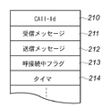
図3Bは、本実施形態を実行するために、RAM162に確保される記憶領域の例を示す図である。尚、図3Bには、以下の説明に必要な情報のみを示し、他は省略している。
FIG. 3B is a diagram illustrating an example of a storage area secured in the
210は、他の各装置とのメッセージのやり取りを識別するための装置特有のCall-Idを記憶する領域である。211は、他の装置からのINVITEリクエストやACK信号等の受信メッセージを記憶する領域である。212は、他の装置へ送信するOK信号等の送信メッセージを記憶する領域である。213は、他の装置との呼接続処理中であることを示す呼接続中フラグの記憶領域である。214は、応答のタイムアウト(本例では、200ミリ秒)を監視するためのメッセージ受信からの経過時間を記憶するタイマ領域である。
An
<本実施形態の画像通信ネットワークでの動作例>
本実施形態の画像通信ネットワークでの動作例を図を参照しながら説明する。
<Operation Example of Image Communication Network of Embodiment>
An operation example in the image communication network of the present embodiment will be described with reference to the drawings.
(動作例1:ネットワーク)
図4は、MFP100とMFP120とのT.38通信と、MFP100とMFP130とのT.38通信が並行して実行される場合の、本実施形態の動作例を示す。
(Operation example 1: Network)
FIG. 4 shows an operation example of this embodiment when T.38 communication between the
MFP120からMFP100にT.38の通信が最初に実行され、SIPプロトコルに基づきMFP120からSIPサーバ122に、呼制御リクエスト・メッセージであるINVITEリクエスト300が送られる。以下、表現をINVITEリクエストで統一する。INVITEリクエスト300を受信したSIPサーバ122は、その応答としてMFP120にTrying信号303を返答して、SIPサーバ102にINVITEリクエスト301を送信する。INVITEリクエスト301を受信したSIPサーバ102は、その応答としてSIPサーバ102にTrying信号304を返答して、MFP100にINVITEリクエスト302を送信する(以下、TryingのメッセージもTrying信号と呼ぶ)。
T.38 communication is first executed from the
INVITEリクエスト302を受信したMFP100は、機器の状態を呼び出し中状態に変化させて呼び出し音を鳴らす。そして、INVITEリクエスト302の応答として、SIPサーバ102にRinging信号305を返答する。以下、RingingのメッセージもRinging信号と呼ぶ。
Receiving the
この呼制御通信を実行している最中の状態で、MFP130からMFP100にT.38の通信が実行されると、SIPプロトコルに基づきMFP130からSIPサーバ132にINVITEリクエスト330が送られる。INVITEリクエスト330を受信したSIPサーバ132は、その応答としてMFP130にTrying信号333を返答して、SIPサーバ102にINVITEリクエスト331を送信する。INVITEリクエスト331を受信したSIPサーバ102は、その応答としてSIPサーバ132にTrying信号334を返答して、MFP100にINVITEリクエスト332を送信する。
When T.38 communication is executed from the
ここで、本実施形態におけるMFP100は、すでにMFP120とのSIPセッションを実行しているために、MFP130からのリクエストには応答しない。即ち、本来はMFP130に対して返答すべきRinging信号をすぐには返答せずに、MFP120とのSIPセッションが終了した後で返答するように通信制御する。
Here, the
一方、MFP120からのINVITEリクエストに基づくRinging信号305を受信したSIPサーバ102は、SIPサーバ122にMFP100が呼び出し中状態になったことを示すRinging信号306を返答する。Ringing信号306を受信したSIPサーバ122は、MFP120にRinging信号307を返答し、MFP100が呼び出し中であることを知ることができる。
On the other hand, the
MFP100ではMFP120からの画像データを受信することができる状態になると、SIPサーバ102にOK信号308を返答する。この応答を受けたSIPサーバ102は、SIPサーバ122にOK信号309を返答する。SIPサーバ122はMFP120にOK信号310を返答することで、MFP120はMFP100がデータ受信可能状態になったことが解る。以下、OKのメッセージもOK信号と呼ぶ。
When the
MFP120は、MFP100がデータ受信可能になったことで、MFP100に対して直接ACK信号311を送信し、これからデータを送信することを伝える。以下、ACKのメッセージやコマンドもACK信号と呼ぶ。
The
一方、MFP100ではMFP120からの通信とは別にMFP130からのINVITEリクエスト332を受信しているが、MFP120の呼接続処理が終了していないために、このリクエストに関する応答はしない。RFC3261によると最終応答までに200ミリ秒以上要する場合は、暫定応答を返答しなければならないことが決められている。そのために、INVITEリクエスト332受信後、180ミリ秒(335)の時間が経過し、かつMFP120からの通信の呼制御を終えていない場合に、暫定応答コードのTrying信号336をSIPサーバに返答する。なお、180ミリ秒という値は200ミリ秒という規定を守るため20ミリ秒の余裕をもった値として予め定められているものとする。
On the other hand, the
その後、MFP120からの通信は、ACK信号311により呼接続のSIPプロトコル処理が終了し、メディアセッション312〜316(メディアセッション通信)に移行し、画像データがMFP120からMFP100に送信される。MFP120からの通信の複雑なSIPプロトコル処理が終了し、単純なメディアセッションに移行したことにより、一時的に中断していたMFP130との呼制御通信を再開する。
Thereafter, in the communication from the
MFP100は、MFP130からのINVITEリクエストに基づき機器の状態を呼び出し中の状態に変化させて呼び出し音を鳴らす。そして、INVITEリクエスト332の正式応答としてSIPサーバ102にRinging信号337をSIPサーバ102に返答する。このRinging信号を受信したSIPサーバ102はSIPサーバ132にRinging信号338を返答し、SIPサーバ102がMFP130にRinging信号339を送信することで、MFP130でMFP100が呼び出し状態になったことが解る。
Based on the INVITE request from the
MFP100では、MFP130からの画像データを受信することができる状態になると、SIPサーバ102にOK信号340を返答する。この応答を受けたSIPサーバ102はSIPサーバ132にOK信号341を返答し、SIPサーバ132はMFP130にOK信号342を返答することで、MFP130はMFP100がデータ受信可能状態になったことが解る。
When the
MFP130は、MFP100がデータ受信可能になったことで、MFP100に対して直接ACK信号 343を送信し、これからデータを送信することを伝える。344から347がMFP130とMFP100のメディアセッションであり、画像データがMFP130からMFP100に送信される。この間344から316の時間帯は、MFP120からのMFP100へのメディアセッションとMFP130からMFP100のメディアセッションとは重なり、MFP100は2箇所からの画像データを並行に処理することになる。
The
MFP120から送信すべき画像データが終了すると、MFP120がMFP100へBYE信号317を送信する。MFP100がMFP120へOK信号318を返すことでMFP120からMFP100への通信は終了する(以下、BYEのメッセージやコマンドもBYE信号と呼ぶ)。また、MFP130から送信すべき画像データが終了すると、MFP130がMFP100へBYE信号348を送信し、MFP100がMFP120へOK信号349を返すことでMFP130からMFP100への通信は終了する。
When the image data to be transmitted from the
(動作例2:ネットワーク)
図5は、MFP100とMFP120とのT.38通信と、MFP100とMFP130とのT.38通信が並行して実行される場合の、本実施形態の他の動作例を示す。本例では、MFP130からのINVITEリクエストがSIPサーバ102からMFP120に送られる時間が遅延する場合である。
(Operation example 2: Network)
FIG. 5 shows another operation example of this embodiment when T.38 communication between the
MFP120からMFP100にT.38の通信が最初に実行され、SIPプロトコルに基づきMFP120からSIPサーバ122にINVITEリクエスト400が送られる。INVITEリクエスト400を受信したSIPサーバ122は、その応答としてMFP120にTrying信号403を返答して、SIPサーバ102にINVITEリクエスト401を送信する。INVITEリクエスト401を受信したSIPサーバ102は、その応答としてSIPサーバ102にTrying信号404を返答して、MFP100にINVITEリクエスト402を送信する。
T.38 communication is first executed from the
INVITEリクエスト402を受信したMFP100は、機器の状態を呼び出し中状態に変化させて呼び出し音を鳴らす。そしてINVITEリクエスト402の応答として、SIPサーバ102にRinging信号405を返答する。
Receiving the
この呼制御通信を実行している最中の状態で、MFP130からMFP100にT.38の通信が実行されると、SIPプロトコルに基づきMFP130からSIPサーバ132にINVITEリクエスト430が送られる。INVITEリクエスト430を受信したSIPサーバ132は、その応答としてMFP130にTrying信号433を返答して、SIPサーバ102にINVITEリクエスト431を送信する。INVITEリクエスト431を受信したSIPサーバ102は、その応答としてSIPサーバ132にTrying信号434を返答して、MFP100にINVITEリクエスト432を送信する。
When T.38 communication is executed from the
ここで、SIPサーバ102は上述した動作例1とは異なり、Ringing信号405等の処理を行っているなどの理由により、INVITEリクエスト432をMFP100に送信するまでに時間がかかっているものとする。
Here, unlike the operation example 1 described above, it is assumed that it takes time until the
Ringing信号405を受信したSIPサーバ102は、SIPサーバ122に暫定応答メッセージとしてRinging信号406を返答し、MFP100が呼び出し中状態になったことを知らせる。この信号はMFP120にRinging信号407によって知らされる。
The
また、MFP100では、MFP120からの画像データを受信することができる状態になると、SIPサーバ102にOK信号408を返答する。この応答を受けたSIPサーバ102はSIPサーバ122にOK信号409を返答し、SIPサーバ122はMFP120にOK信号410を返答することで、MFP120はMFP100がデータ受信可能状態になったことが解る。MFP120は、MFP100がデータ受信可能になったことで、MFP100に対して直接ACK信号411を送信し、これからデータを送信することを伝える。
When the
この間に、SIPサーバ102よりMFP130からの呼接続に起因するINVITEリクエスト432がMFP100に到着し、MFP100は複数の呼接続要求を受けた状態となっている。
このタイミングでRinging信号を返答してしまうと複数の呼接続要求を実行することになってしまうために、MFP100はすぐにはRinging信号を返答しない。
During this time, the
If the Ringing signal is returned at this timing, a plurality of call connection requests are executed, so the
一方、MFP120からの呼接続要求はACK信号411にて終了してメディアセッション状態となる。以後、MFP100は、MFP120からの画像データからなるメディアセッション412〜416を受信する。
On the other hand, the call connection request from the
MFP100は、MFP120からの呼接続要求が終了したことを判断し、MFP130からのINVITEリクエスト432に対応するRinging信号436をSIPサーバ102に返答する。なお、INVITEリクエスト432からRinging信号436までの時間435は200ミリ秒以下であり、RFC3261の規定以下である。Ringing信号436を受信したSIPサーバ102は、SIPサーバ132にRinging信号437を返答し、MFP100が呼び出し中の状態になったことを知らせ、この信号はMFP130にRinging信号438によって知らされる。
The
MFP100では、MFP130からの画像データを受信することができる状態になると、SIPサーバ102にOK信号439を返答する。この応答を受けたSIPサーバ102はSIPサーバ132にOK信号 440を返答し、SIPサーバ132はMFP130にOK信号441を返答することで、MFP130はMFP100がデータ受信可能状態になったことが解る。
When the
MFP130は、MFP100がデータ受信可能になったことで、MFP100に対して直接ACK信号442を送信し、これからデータを送信することを伝える。
The
MFP130からのメディアセッションが開始され画像データからなるメディアセッション443〜446の通信が行われる。この間、443から416の時間の間は、MFP100はMFP120からのメディアセッションとMFP130からのメディアセッションとを並行に受信する。
A media session from the
MFP120からのメディアセッションが終了すると、MFP120はBYE417を送信し、MFP100からはその応答としてOK信号418を送信し、MFP120とMFP100の一連の通信は終了する。また、MFP130からのメディアセッションが終了すると、MFP130はBYE447を送信し、MFP100からはその応答としてOK信号 448を送信し、MFP120とMFP100の通信は終了する。
When the media session from the
(動作例1及び2を実現する処理手順例)
図6Aは、前記動作例1と2を実現するMFP100の動作手順例を示すフローチャートである。なお、図6Aのフローチャートは、SIPのメッセージを受信した時にインタラプト処理として動作開始する。また、Call-Idを用いて各送信機から送られてくるメッセージが区別され、Call-Id単位でかかるフローチャートの処理が実行される。即ち、このフローチャートは複数が並行して実行される(図6B参照)。
(Example of processing procedure for realizing operation examples 1 and 2)
FIG. 6A is a flowchart showing an operation procedure example of the
MFP100おいてSIP呼接続が開始されると、S500のSIP受信処理が開始される。
S501はメッセージ受信処理であり、INVITEリクエスト302などのメッセージを受信する処理である。メッセージ受信後に、メッセージを受信してから応答を返答するまでの時間を計測するタイマをスタートさせる(S502)。S503は受信したメッセージを解析する処理である。
When SIP call connection is started in
S501 is a message reception process, which is a process of receiving a message such as the
S504では受信したメッセージがINVITEリクエストであるか調べ、S505では受信したメッセージがACK信号であるか調べる。これ以外のメッセージを受信した場合は、S506でエラーが通知され、S522にて応答時間を計測するタイマを止めて値をクリアして、S523で処理を終了する。 In S504, it is checked whether the received message is an INVITE request. In S505, it is checked whether the received message is an ACK signal. If any other message is received, an error is notified in S506, the timer for measuring the response time is stopped in S522, the value is cleared, and the process ends in S523.
(INVITEリクエスト)
受信したメッセージがINVITEリクエストである場合、S509に処理が移行し、既に他の通信により呼接続中であるかが呼接続中フラグにより判断される。呼接続中でない場合(呼接続中フラグがOFF)は、S510により新規メッセージとして処理され必要なメモリ領域などが確保され、S511でシステムの状態を呼接続中に変更する(呼接続中フラグをONにする)。
(INVITE request)
If the received message is an INVITE request, the process proceeds to S509, and it is determined by the call connection flag whether the call is already connected by another communication. If the call connection is not in progress (the call connection flag is OFF), it is processed as a new message by S510 and the necessary memory area is secured, and the system status is changed to call connection in S511 (the call connection flag is set to ON). ).
その後、S518でRinging信号を送信し、S519で呼び出し音を鳴らす。S520でメディアセッションの画像データが受信可能な状態であるか判断され、受信可能でない場合はS519に戻る。一方、受信可能な場合はS521でOK信号の返答を送信し、S522にて応答時間を計測するタイマが止められ終了する。 Thereafter, a Ringing signal is transmitted in S518, and a ringing tone is emitted in S519. In S520, it is determined whether the image data of the media session is receivable. If not, the process returns to S519. On the other hand, if reception is possible, an OK signal response is transmitted in S521, and the timer for measuring the response time is stopped and terminated in S522.
S509ですでに装置の状態が呼接続中であった場合(呼接続中フラグがON)、S512で接続してきたINVITEリクエストのCall-Idと既に接続済みのJOBのCall-Idを比較する。接続してきたINVITEリクエストのCall-Idが既に存在していた場合は、同一機器から同じ通信で多重にINVITEリクエストが送信されたので、S513のRe-INVITE処理を行い、S522にプログラムを遷移させる。 If the state of the device is already connected in S509 (the call connection flag is ON), the Call-Id of the INVITE request connected in S512 is compared with the Call-Id of the already connected job. If the Call-Id of the connected INVITE request already exists, multiple INVITE requests are transmitted from the same device through the same communication, so the Re-INVITE process of S513 is performed, and the program is shifted to S522.
Call-Idが同一ではない場合、S514にてS502でスタートさせたタイマが180ミリ秒以上であるか調査する。タイマ値が180ミリ秒以下で、S516の判定で呼接続中である場合は、S517でTask_Delay処理を実行し、自らの動作は一定時間動作させず、他のタスクのプログラムを優先的に動作させ、S514に戻る。タイマ値が180ミリ秒以上になった場合は、S515でTrying信号メッセージを送信し、S524でタイマをリセットして再スタートし、S514に戻る。このメッセージがTrying信号336となる。なお上記180ミリ秒という値はRFC3261で規定されている200ミリ秒以内に応答を返さなければいけないという、規定より20ミリ秒の時間的余裕を見積もった値であり、335の時間に相当する。
If the Call-Ids are not the same, it is checked in S514 if the timer started in S502 is 180 milliseconds or longer. If the timer value is 180 milliseconds or less and the call is being connected as determined in S516, Task_Delay processing is executed in S517, and its own operation is not operated for a certain period of time, and other task programs are preferentially operated. Return to S514. If the timer value is 180 milliseconds or more, a Trying signal message is transmitted in S515, the timer is reset and restarted in S524, and the process returns to S514. This message becomes a Trying
これらの処理により、以下のような図4及び図5の処理が行われる。まず、他のSIP接続中のJOBが存在している状態で新たにSIP接続がされた場合、新たに接続されたJOBのSIP接続処理は行わない。そして、180ミリ秒以内に接続中の他のJOBがメディアッセッションに移行した場合は移行してから新たに接続してきたJOBのSIP接続処理を行う。一方、180ミリ秒を超えた場合は暫定応答のTrying信号メッセージを一旦返答し、接続中の他のJOBがメディアッセッションに移行してから新たに接続してきたJOBのSIP接続処理を行う。 By these processes, the following processes shown in FIGS. 4 and 5 are performed. First, when a new SIP connection is made in a state where another SIP connected job exists, the SIP connection processing of the newly connected job is not performed. If another connected job is transferred to the media session within 180 milliseconds, SIP connection processing for the newly connected job is performed after the transfer. On the other hand, if it exceeds 180 milliseconds, a temporary response Trying signal message is returned once, and the SIP connection processing of the newly connected job is performed after the other connected job shifts to the media session.
図6Aに戻り、優先させて処理を行ったプログラム動作により、接続中の他のセッションが呼接続中状態を終了してメディアッセッションに移行した場合、処理はS518に移行する。 Returning to FIG. 6A, when another session that is connected ends the call connection state and shifts to the media session by the program operation that has been processed with priority, the process shifts to S518.
S518はRinging信号メッセージを送信する処理であり、メッセージ送信後、S519の呼び出し音を鳴らす処理を実行する。S519終了後、S520で機器の状態がメディアセッションのデータを受信可能であるか調べ、受信可能でない場合はS519に戻り、可能な場合はS521でOK信号メッセージを送信して、S522に移行する。 S518 is a process of transmitting a Ringing signal message. After the message is transmitted, a process of sounding a ringing tone of S519 is executed. After completion of S519, it is checked in S520 whether the status of the device can receive the data of the media session. If not, the process returns to S519, and if possible, an OK signal message is transmitted in S521, and the process proceeds to S522.
(ACKメッセージ)
受信したメッセージがACK信号である場合、S507にてメディアセッションへの移行処理を行い、S508にて呼接続中フラグをリセットし、呼接続状態を終了してメディアセッション状態としてS522に移行する。
(ACK message)
If the received message is an ACK signal, a transition process to the media session is performed in S507, the call connection flag is reset in S508, the call connection state is terminated, and the process shifts to S522 as the media session state.
(図4,図5,図6A及び図6Bによる具体的説明)
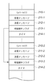
図6Bは、上記図6Aのフローチャートで図4又は図5の処理を実行中のRAM162の様子の概略を示した図である。図6Aの処理手順の理解のために、図4又は図5の処理に従い説明する。尚、以下では、MFP120からのメッセージに基づくSIP受信処理の各ステップをSXXXAと示し、MFP130からのメッセージに基づくSIP受信処理の各ステップをSXXXBと示す。
(Specific description according to FIG. 4, FIG. 5, FIG. 6A and FIG. 6B)
FIG. 6B is a diagram showing an outline of the state of the
MFP120からのINVITEリクエストがMFP100に送信されると、図6Bの210-1から214-1が確保されて、Call-Id(1)210-1にはMFP120のIdが格納される。図6Aのフローチャートは、S501A-S502A-S503A-S504A-S509A-S510A-S511Aと進み、S511Aでは呼接続中フラグ213-1がセットされる。図6Aのフローチャートは、S518A-S519Aに進み、Ringing信号が応答され、MFP100で呼び出し音が鳴る。そして、S520AでMFP100がデータ受信可に成るのを待つ。
When the INVITE request from
(図4の例)
ここで、S520AにおいてMFP100がデータ受信可に成る前に、MFP130からのINVITEリクエストがMFP100に送信されると、図4の処理になる。
(Example of FIG. 4)
Here, when the INVITE request from the
MFP130からのINVITEリクエストを受けて、図6Aのフローチャートがスタートする。この場合に、MFP120からのINVITEリクエストに基づく図6Aの処理は並行に処理され、S519A-S520Aでループしている。又、図6Bの210-2から214-2が確保されて、Call-Id(2)210-2にはMFP130のIdが格納される。同時に、呼接続中フラグ213-2には呼接続中フラグ213-1がコピーされて、フラグはONとなる。
In response to the INVITE request from the
図6Aのフローチャートは、S501B-S502B-S503B-S504B-S509B-S512B-S514Bと進む。そして、まず呼接続中フラグがONなのでS514B-S516B-S517Bのループに入り、INVITEリクエストに応答するRinging処理には進まない。 The flowchart of FIG. 6A proceeds with S501B-S502B-S503B-S504B-S509B-S512B-S514B. First, since the call connection flag is ON, the process enters the loop of S514B-S516B-S517B and does not proceed to the Ringing process in response to the INVITE request.
図4の例では、この間にMFP100がデータ受信可となり、S519A-S520Aのループを抜けて、S521AでOK信号送信を行う。
In the example of FIG. 4, the
一方、S514B-S516B-S517Bのループでタイマの値が180ミリ秒に成ると、S514B-S515B-S524Bの処理でTrying信号336を送信して、再びS514B-S516B-S517Bのループに戻る。
On the other hand, when the timer value reaches 180 milliseconds in the loop of S514B-S516B-S517B, a Trying
この間に、S521AでのOK信号送信がMFP120まで届いて、MFP120が直接MFP100にACK信号を送信すると、SIP受信処理が再度スタートする。図6Aのフローチャートは、S501A-S502A-S503A-S504A-S505A-S507-S508Aと進んで、呼接続処理からメディアセッションに移行して、S508Aで呼接続中フラグがOFFとなる。
During this time, when the OK signal transmission in S521A reaches the
MFP130からのINVITEリクエストに基づくフローは、S516Bで呼接続中フラグがOFFとなったことを認識して、S518以降に進む。以下、Ringing処理、OK信号送信、ACK信号受信で呼接続処理からメディアセッションへの移行への進む。
The flow based on the INVITE request from the
(図5の例)
SIPサーバ102の処理の遅延で、S520AにおいてMFP100がデータ受信可に成る前に、MFP130からのINVITEリクエストがMFP100に送信されないと、図5の処理となる。
(Example of FIG. 5)
If the INVITE request from the
MFP130からのINVITEリクエストがMFP100に送信される前に、S520AからS521Aに抜けてOK信号が送信される。その後に、INVITEリクエストがMFP100に送信されて、上記図4と同様にSXXXBで示した処理が行われる。
Before an INVITE request from the
図4との相違は、S514Bの判定でタイマが180ミリ秒に到達する前に、S521AでのOK信号送信がMFP120に届いて、MFP120がACK信号を送信する。従って、呼接続処理からメディアセッションに移行して、S508Aで呼接続中フラグがOFFとなることである。
The difference from FIG. 4 is that the OK signal transmission in S521A reaches the
従って、S515BでのTrying信号の送信なしに、S516BからS518Bに抜けて、MFP130からのINVITEリクエストに対するRinging処理が開始される。
Therefore, without transmitting the Trying signal in S515B, the process exits from S516B to S518B, and the Ringing process for the INVITE request from the
(動作例3)
図7は、MFP100とMFP120とのT.38通信と、MFP100とMFP130とのT.38通信がほぼ同時に実行された場合の、本実施形態の動作例3を示す。
(Operation example 3)
FIG. 7 shows an operation example 3 of the present embodiment when T.38 communication between the
MFP120からMFP100にT.38の通信が最初に実行され、SIPプロトコルに基づきMFP120からSIPサーバ122にINVITEリクエスト600が送られる。INVITEリクエスト600を受信したSIPサーバ122は、その応答としてMFP120にTrying信号603を返答して、SIPサーバ102にINVITEリクエスト601を送信する。INVITEリクエスト601を受信したSIPサーバ102は、その応答としてSIPサーバ102にTrying信号604を返答して、MFP100にINVITEリクエスト602を送信する。
T.38 communication is first executed from the
INVITEリクエスト602を受信したMFP100は、機器の状態を呼び出し中状態に変化させて呼び出し音を鳴らす。そして、INVITEリクエスト602の応答としてSIPサーバ102にRinging信号605を返答する。
Receiving the
この呼制御通信を実行している最中の状態で、MFP130からMFP100にT.38の通信が実行されると、SIPプロトコルに基づきMFP130からSIPサーバ132にINVITEリクエスト630が送られる。INVITEリクエスト630を受信したSIPサーバ132は、その応答としてMFP130にTrying信号633を返答して、SIPサーバ102にINVITEリクエスト631を送信する。INVITEリクエスト631を受信したSIPサーバ102は、その応答としてSIPサーバ132にTrying信号634を返答して、MFP100にINVITEリクエスト632を送信する。
When T.38 communication is executed from the
しかしながら、MFP100ではMFP120からのINVITEリクエストを受信、呼接続中であるために、後から接続してきたMFP130からの処理ができない。そのため、ビジーであることを報知するBUSY信号635を返答するよう通信制御する。以下、ビジーメッセージもBUSY信号と呼ぶ。このBUSY信号は、BUSY信号636、BUSY信号637としてSIPサーバ102、SIPサーバ132を経由して、MFP130まで伝えられる。このメッセージを受信したMFP130は、MFP100がBUSY状態で新たなメッセージ処理ができないことを知ることができる。
However, since the
この間に、Ringing信号605は、Ringing信号606、Ringing信号607としてSIPサーバ102、SIPサーバ122を経由して、MFP120に伝えられる。
During this time, the
そして、MFP100は、画像データからなるメディアセッションの受信が可能となると、OK信号メッセージ608を送信する。このメッセージはOK信号609、OK信号610としてSIPサーバ102、SIPサーバ122を経由して、MFP120に伝えられる。
OK信号610を受信したMFP120は、MFP100に対して直接ACK信号611を送信し、これから画像データを送信することを伝える。612から616がメディアセッション中の画像データであり、MFP120からMFP100に送信される。
Receiving the
MFP120から送信すべき画像データが終了すると、MFP120がMFP100へBYE信号617を送信し、MFP100がMFP120へOK信号618を返すことで、MFP120からMFP100への通信は終了する。
When the image data to be transmitted from the
一方、BUSY信号637を受信したMFP130は、JOBの再送信を実施する。再送信のINVITEリクエストが638であり、このメッセージを受信したSIPサーバ122は、その応答としてMFP120にTrying信号641を返答して、SIPサーバ102にINVITEリクエスト639を送信する。INVITEリクエスト639を受信したSIPサーバ102は、その応答としてSIPサーバ102にTrying信号642を返答して、MFP100にINVITEリクエスト640を送信する。
On the other hand, the
INVITEリクエスト640を受信したMFP100は、MFP120からの呼接続状態が呼接続中からメディアセッションに移行したことにより、BUSY信号ではなくRinging信号643を送信し、MFP130からの呼接続を処理する。このRinging信号は、Ringing信号644、Ringing信号645としてSIPサーバ102、SIPサーバ132を経由して、MFP130へと伝えられる。
Receiving the
MFP100では、MFP130からの画像データからなるメディアセッションを受信可能となると、OK信号メッセージ646を送信する。このメッセージはOK信号647、OK信号648としてSIPサーバ102、SIPサーバ132を経由して、MFP130に伝えられる。OK信号648を受信したMFP130は、MFP100に対して直接ACK信号649を送信し、これから画像データを送信することを伝える。650から653がメディアセッション中の画像データであり、MFP120からMFP100に送信される。
When the
MFP100では、650から616の時間帯はMFP120からの画像データとMFP130の画像データの双方を並行に処理することとなる。MFP130から送信すべき画像データが終了すると、MFP130がMFP100へBYE信号654を送信し、MFP100がMFP130へOK信号655を返すことで、MFP130からMFP100への通信は終了する。
In the
(動作例3を実現する処理手順例)
図8は、前記動作例3を実現するMFP100の動作手順例を示すフローチャートである。なお、図6Aのフローチャートは、SIPのメッセージを受信した時にインタラプト処理として動作開始する。また、本動作例3は、各Call-Id単位でかかるフローチャートの処理が複数が並行して実行されても、単純にインタラプト処理によるCall-Returnで実行されても可能である。
(Example of processing procedure for realizing operation example 3)
FIG. 8 is a flowchart showing an operation procedure example of the
MFP100おいてSIP呼接続が開始されると、S700のSIP受信処理が開始される。
When SIP call connection is started in
S701はメッセージ受信処理であり、INVITEリクエスト602などのメッセージを受信する処理であり、メッセージ受信後に、メッセージを受信してから応答を返答するまでの時間を計測するタイマをスタートさせる(S702)。S703は受信したメッセージを解析する処理である。
S701 is a message reception process, which is a process for receiving a message such as the
S704では受信したメッセージがINVITEリクエストであるか調べ、S705では受信したメッセージがACK信号であるか調べる。これ以外のメッセージを受信した場合は、S707でエラーが通知され、S709にて応答時間を計測するタイマを止めて値をクリアして、終了する(S720)。 In S704, it is checked whether the received message is an INVITE request, and in S705, it is checked whether the received message is an ACK signal. If any other message is received, an error is notified in S707, the timer for measuring the response time is stopped in S709, the value is cleared, and the process ends (S720).
(INVITEリクエスト)
受信したメッセージがINVITEリクエストである場合、S710に処理が移行し、既に他の通信により呼接続中であるか判断される。既に呼接続中である場合(呼接続中フラグがON)、S712にてBUSY信号を送信して、S709に遷移する。このBUSY信号がBUSY信号635に該当する。
(INVITE request)
If the received message is an INVITE request, the process proceeds to S710, and it is determined whether the call is already connected by another communication. If the call is already connected (call connection flag is ON), a BUSY signal is transmitted in S712, and the process proceeds to S709. This BUSY signal corresponds to the
呼接続中でない場合は、S714により新規メッセージとして処理され必要なメモリ領域などが確保され、S715でシステムの状態を呼接続中に変更する(呼接続中フラグがONにする)。 If the call is not connected, it is processed as a new message by S714 to secure a necessary memory area and the like, and the system status is changed to call connected in S715 (the call connection flag is turned ON).
その後、S717にて呼び出し音を鳴らす処理を実行し、S718で機器が画像データからなるメディアセッションのデータを受信できる状態であるか調べ、受信できない場合は、S717に戻る。受信可能である場合は、S719でOK信号メッセージを送信し、S709に遷移する。 Thereafter, a process of ringing a ringing tone is executed in S717. In S718, it is checked whether the device is in a state where it can receive media session data consisting of image data. If reception is possible, an OK signal message is transmitted in S719, and the process proceeds to S709.
(ACKメッセージ)
受信したメッセージがACK信号である場合、S706にてメディアセッションへの移行処理を行い、S708にて呼接続状態を終了して(呼接続中フラグをOFFにして)、メディアセッション状態としてS709に移行する。
(ACK message)
If the received message is an ACK signal, the transition to the media session is performed in S706, the call connection state is terminated in S708 (the call connection flag is turned OFF), and the transition to S709 is made as the media session state. To do.
なお、呼制御プロトコルとSIPを使って説明したが、本発明は受信機MFP100の処理に特徴があり、ITU-T勧告のH.323等の他の呼制御を用いても同様な効果が得られる。
Although described using the call control protocol and SIP, the present invention is characterized by the processing of the
又、本発明は、複数の機器(例えばホストコンピュータ、インターフェース機器、プリンタなど)から構成されるシステムあるいは統合装置に適用しても、ひとつの機器からなる装置に適用してもよい。 In addition, the present invention may be applied to a system or an integrated device composed of a plurality of devices (for example, a host computer, an interface device, a printer, etc.) or an apparatus composed of a single device.
又、本発明の目的は、前述した実施形態の機能を実現するソフトウェアのプログラムコードを記録した記憶媒体(または記録媒体)を、システムあるいは装置に供給する。そして、そのシステムあるいは装置のコンピュータ(またはCPUやMPU)が記憶媒体に格納されたプログラムコードを読み出し実行することによっても、達成されることは言うまでもない。 Another object of the present invention is to supply a storage medium (or recording medium) in which a program code of software that realizes the functions of the above-described embodiments is recorded to a system or apparatus. Needless to say, this can also be achieved by the computer (or CPU or MPU) of the system or apparatus reading and executing the program code stored in the storage medium.
この場合、記憶媒体から読み出されたプログラムコード自体が前述した実施形態の機能を実現することになり、そのプログラムコードを記憶した記憶媒体は本発明を構成することになる。 In this case, the program code itself read from the storage medium realizes the functions of the above-described embodiments, and the storage medium storing the program code constitutes the present invention.
又、コンピュータが読み出したプログラムコードを実行することにより、前述した実施形態の機能が実現されるだけではない。そのプログラムコードの指示に基づき、コンピュータ上で稼働しているオペレーティングシステム(OS)などが実際の処理の一部または全部を行い、その処理によって前述した実施形態の機能が実現される場合も含まれることは言うまでもない。 The functions of the above-described embodiments are not only realized by executing the program code read by the computer. This includes the case where the operating system (OS) running on the computer performs part or all of the actual processing based on the instruction of the program code, and the functions of the above-described embodiments are realized by the processing. Needless to say.
さらに、記憶媒体から読み出されたプログラムコードが、コンピュータに挿入された機能拡張カードやコンピュータに接続された機能拡張ユニットに備わるメモリに書込まれる。その後、そのプログラムコードの指示に基づき、その機能拡張カードや機能拡張ユニットに備わるCPUなどが実際の処理の一部または全部を行う。このような処理によって前述した実施形態の機能が実現される場合も含まれることは言うまでもない。 Further, the program code read from the storage medium is written in a memory provided in a function expansion card inserted into the computer or a function expansion unit connected to the computer. Thereafter, based on the instruction of the program code, the CPU provided in the function expansion card or function expansion unit performs part or all of the actual processing. It goes without saying that the case where the functions of the above-described embodiments are realized by such processing is also included.
本発明を上記記憶媒体に適用する場合、その記憶媒体には、先に説明したフローチャートに対応するプログラムコードが格納されることになる。 When the present invention is applied to the storage medium, the storage medium stores program codes corresponding to the flowcharts described above.
100、120、130 MFP
102、122、132 SIPサーバ
103、123 メールサーバ
106、126 T.38GW
104、124 IP電話機
105、125 電話機
100, 120, 130 MFP
102, 122, 132 SIP server
103, 123 Mail server
106, 126 T.38GW
104, 124 IP phones
105, 125 telephone
Claims (8)
送信装置からのメッセージを受信するメッセージ受信手段と、
前記メッセージ受信手段が受信したメッセージに対する応答を前記送信装置に送信するメッセージ送信手段と、
第1の送信装置からの呼制御リクエスト・メッセージを受信して前記第1の送信装置との呼制御を実行している途中に、第2の送信装置からの呼制御リクエスト・メッセージを受信した場合、前記第2の送信装置からの呼制御リクエスト・メッセージに対する応答を、前記第1の送信装置との呼制御が終了した後に送信し、前記第1の送信装置との画像データの通信と並行して前記第2の送信装置との呼制御を実行するよう制御する通信制御手段と、
を備えることを特徴とする画像通信装置。 An image communication apparatus for communicating image data using a call control protocol,
Message receiving means for receiving a message from the transmitting device;
Message sending means for sending a response to the message received by the message receiving means to the sending device;
When a call control request message is received from the second transmitter while the call control request message from the first transmitter is received and call control with the first transmitter is being executed A response to the call control request message from the second transmission device is transmitted after the call control with the first transmission device is completed , and in parallel with image data communication with the first transmission device. Communication control means for controlling to execute call control with the second transmission device ;
An image communication apparatus comprising:
送信装置からのメッセージを受信するメッセージ受信手段と、
前記メッセージ受信手段が受信したメッセージに対する応答を前記送信装置に送信するメッセージ送信手段と、
第1の送信装置からの呼制御リクエスト・メッセージを受信して前記第1の送信装置との呼制御を実行している途中に、第2の送信装置からの呼制御リクエスト・メッセージを受信した場合は、前記第2の送信装置からの呼制御リクエスト・メッセージに対する応答として、他の装置と通信中であることを示すメッセージを前記第2の送信装置に送信し、前記第1の送信装置との呼制御が終了し、前記第1の送信装置との画像データの通信を開始した後に、前記第2の送信装置からの呼制御リクエスト・メッセージを受信した場合は、前記第1の送信装置との画像データの通信と並行して前記第2の送信装置との呼制御を実行するよう制御する通信制御手段と、
を備えることを特徴とする画像通信装置。 An image communication apparatus for communicating image data using a call control protocol,
Message receiving means for receiving a message from the transmitting device;
Message sending means for sending a response to the message received by the message receiving means to the sending device;
When a call control request message is received from the second transmitter while the call control request message from the first transmitter is received and call control with the first transmitter is being executed as a response to the call control request message from the second transmission device transmits a message indicating that it is communicating with another device to the second transmission device, between the first transmission device When a call control request message is received from the second transmitter after the call control is completed and image data communication with the first transmitter is started, the communication with the first transmitter is performed. Communication control means for controlling to execute call control with the second transmission device in parallel with communication of image data ;
An image communication apparatus comprising:
メッセージ受信手段が、送信装置からのメッセージを受信するメッセージ受信工程と、
メッセージ送信手段が、前記メッセージ受信工程で受信したメッセージに対する応答を前記送信装置に送信するメッセージ送信工程と、
通信制御手段が、第1の送信装置からの呼制御リクエスト・メッセージを受信して前記第1の送信装置との呼制御を実行している途中に、第2の送信装置からの呼制御リクエスト・メッセージを受信した場合、前記第2の送信装置からの呼制御リクエスト・メッセージに対する応答を、前記第1の送信装置との呼制御が終了した後に送信し、前記第1の送信装置との画像データの通信と並行して前記第2の送信装置との呼制御を実行するよう制御する通信制御工程と、
を備えることを特徴とする通信方法。 A communication method of an image communication apparatus that performs image data communication using a call control protocol,
A message receiving means for receiving a message from the transmitting device;
A message transmission step in which a message transmission means transmits a response to the message received in the message reception step to the transmission device;
While the communication control means receives the call control request message from the first transmitting device and executes the call control with the first transmitting device, the call control request from the second transmitting device When a message is received, a response to the call control request message from the second transmission device is transmitted after call control with the first transmission device is completed , and image data with the first transmission device is transmitted. A communication control step for controlling to execute call control with the second transmission device in parallel with the communication of
A communication method comprising:
メッセージ受信手段が、送信装置からのメッセージを受信するメッセージ受信工程と、
メッセージ送信手段が、前記メッセージ受信工程で受信したメッセージに対する応答を前記送信装置に送信するメッセージ送信工程と、
通信制御手段が、第1の送信装置からの呼制御リクエスト・メッセージを受信して前記第1の送信装置との呼制御を実行している途中に、第2の送信装置からの呼制御リクエスト・メッセージを受信した場合は、前記第2の送信装置からの呼制御リクエスト・メッセージに対する応答として、他の装置と通信中であることを示すメッセージを前記第2の送信装置に送信し、前記第1の送信装置との呼制御が終了し、前記第1の送信装置との画像データの通信を開始した後に、前記第2の送信装置からの呼制御リクエスト・メッセージを受信した場合は、前記第1の送信装置との画像データの通信と並行して前記第2の送信装置との呼制御を実行するよう制御する通信制御工程と、
を備えることを特徴とする通信方法。 A communication method of an image communication apparatus that performs image data communication using a call control protocol,
A message receiving means for receiving a message from the transmitting device;
A message transmission step in which a message transmission means transmits a response to the message received in the message reception step to the transmission device;
While the communication control means receives the call control request message from the first transmitting device and executes the call control with the first transmitting device, the call control request from the second transmitting device when receiving a message, and sends the response to the call control request message from the second transmitter, the second transmitter device a message indicating that it is communicating with another device, the first When a call control request message is received from the second transmitter after the call control with the first transmitter is completed and image data communication with the first transmitter is started, the first A communication control step for performing control to perform call control with the second transmission device in parallel with communication of image data with the transmission device of
A communication method comprising:
Priority Applications (2)
| Application Number | Priority Date | Filing Date | Title |
|---|---|---|---|
| JP2007036806A JP4869100B2 (en) | 2007-02-16 | 2007-02-16 | Communication method and image communication apparatus |
| US12/014,481 US8180031B2 (en) | 2007-02-16 | 2008-01-15 | Data communication apparatus and data communication method |
Applications Claiming Priority (1)
| Application Number | Priority Date | Filing Date | Title |
|---|---|---|---|
| JP2007036806A JP4869100B2 (en) | 2007-02-16 | 2007-02-16 | Communication method and image communication apparatus |
Publications (3)
| Publication Number | Publication Date |
|---|---|
| JP2008205617A JP2008205617A (en) | 2008-09-04 |
| JP2008205617A5 JP2008205617A5 (en) | 2010-04-02 |
| JP4869100B2 true JP4869100B2 (en) | 2012-02-01 |
Family
ID=39706670
Family Applications (1)
| Application Number | Title | Priority Date | Filing Date |
|---|---|---|---|
| JP2007036806A Expired - Fee Related JP4869100B2 (en) | 2007-02-16 | 2007-02-16 | Communication method and image communication apparatus |
Country Status (2)
| Country | Link |
|---|---|
| US (1) | US8180031B2 (en) |
| JP (1) | JP4869100B2 (en) |
Families Citing this family (4)
| Publication number | Priority date | Publication date | Assignee | Title |
|---|---|---|---|---|
| US8719926B2 (en) * | 2011-02-11 | 2014-05-06 | Verizon Patent And Licensing Inc. | Denial of service detection and prevention using dialog level filtering |
| JP6026360B2 (en) * | 2013-06-21 | 2016-11-16 | 京セラドキュメントソリューションズ株式会社 | Image forming method |
| US9648202B2 (en) * | 2014-07-18 | 2017-05-09 | Hewlett-Packard Development Company, L.P. | Transmitting a job to a destination using a destination notification manager and a delivery agent |
| JP6504341B2 (en) * | 2015-01-20 | 2019-04-24 | 富士ゼロックス株式会社 | Information processing apparatus and program |
Family Cites Families (4)
| Publication number | Priority date | Publication date | Assignee | Title |
|---|---|---|---|---|
| JP3772836B2 (en) * | 2003-01-27 | 2006-05-10 | 村田機械株式会社 | Communication terminal device |
| JP4576115B2 (en) | 2003-12-18 | 2010-11-04 | 株式会社日立製作所 | VoIP gateway device and method for controlling call arrival and departure in VoIP gateway device |
| JP2005269165A (en) | 2004-03-18 | 2005-09-29 | Sanyo Electric Co Ltd | Ip phone |
| JP2005311670A (en) | 2004-04-21 | 2005-11-04 | Ntt Comware Corp | Terminal, system and method for television conference, and program therefor |
-
2007
- 2007-02-16 JP JP2007036806A patent/JP4869100B2/en not_active Expired - Fee Related
-
2008
- 2008-01-15 US US12/014,481 patent/US8180031B2/en not_active Expired - Fee Related
Also Published As
| Publication number | Publication date |
|---|---|
| JP2008205617A (en) | 2008-09-04 |
| US8180031B2 (en) | 2012-05-15 |
| US20080198986A1 (en) | 2008-08-21 |
Similar Documents
| Publication | Publication Date | Title |
|---|---|---|
| US20080117477A1 (en) | Facsimile apparatus and control method therefor | |
| JP2003233558A (en) | Communication device and its control method | |
| JP2007180614A (en) | Transmitting device and receiver and method of controlling them, communication system, and program | |
| JP2010183340A (en) | Facsimile machine, method for controlling the same, and program | |
| JP2012244485A (en) | Image forming apparatus, image forming system, control method for image forming system, and program | |
| JP6217604B2 (en) | Communication system, communication method, device with gateway function, and program | |
| JP4869100B2 (en) | Communication method and image communication apparatus | |
| JP2006261855A (en) | Image forming apparatus, image-forming method, program, and storage medium | |
| US8958098B2 (en) | Communication device allowing proxy reception of data directed thereto, and control method and storage medium therefor | |
| JP2011029821A (en) | Information processing apparatus, control method of the information processing apparatus, and control program for the information processing apparatus | |
| US9203984B2 (en) | Communication apparatus and communication system | |
| JP3656375B2 (en) | Communication network system | |
| JP6447263B2 (en) | Facsimile apparatus, image forming apparatus, and program | |
| JP6391238B2 (en) | System, facsimile apparatus, control method, and program | |
| JP4927143B2 (en) | Reception device, control method therefor, and program | |
| US9209997B2 (en) | Communication apparatus and communication system | |
| JP2013031019A (en) | Communication device | |
| JP5371603B2 (en) | Facsimile apparatus, control method and program for facsimile apparatus | |
| JP7143676B2 (en) | Image forming apparatus and receiving transfer method | |
| JP3636085B2 (en) | Internet facsimile communication method and internet facsimile apparatus | |
| JP6307197B2 (en) | Facsimile apparatus, control method thereof, and program | |
| JP3882812B2 (en) | Internet facsimile machine | |
| JP2008236106A (en) | Image transfer device, image reception device, and image transfer system equipped therewith | |
| JP2009049865A (en) | Network facsimile apparatus | |
| US20100053666A1 (en) | Image communication apparatus and computer readable medium |
Legal Events
| Date | Code | Title | Description |
|---|---|---|---|
| A521 | Request for written amendment filed |
Free format text: JAPANESE INTERMEDIATE CODE: A523 Effective date: 20100216 |
|
| A621 | Written request for application examination |
Free format text: JAPANESE INTERMEDIATE CODE: A621 Effective date: 20100216 |
|
| A977 | Report on retrieval |
Free format text: JAPANESE INTERMEDIATE CODE: A971007 Effective date: 20110606 |
|
| A131 | Notification of reasons for refusal |
Free format text: JAPANESE INTERMEDIATE CODE: A131 Effective date: 20110624 |
|
| A521 | Request for written amendment filed |
Free format text: JAPANESE INTERMEDIATE CODE: A523 Effective date: 20110823 |
|
| TRDD | Decision of grant or rejection written | ||
| A01 | Written decision to grant a patent or to grant a registration (utility model) |
Free format text: JAPANESE INTERMEDIATE CODE: A01 Effective date: 20111114 |
|
| A01 | Written decision to grant a patent or to grant a registration (utility model) |
Free format text: JAPANESE INTERMEDIATE CODE: A01 |
|
| A61 | First payment of annual fees (during grant procedure) |
Free format text: JAPANESE INTERMEDIATE CODE: A61 Effective date: 20111115 |
|
| FPAY | Renewal fee payment (event date is renewal date of database) |
Free format text: PAYMENT UNTIL: 20141125 Year of fee payment: 3 |
|
| LAPS | Cancellation because of no payment of annual fees |