JP4868630B2 - Memory system configuration method and memory system configuration apparatus - Google Patents
Memory system configuration method and memory system configuration apparatus Download PDFInfo
- Publication number
- JP4868630B2 JP4868630B2 JP06374099A JP6374099A JP4868630B2 JP 4868630 B2 JP4868630 B2 JP 4868630B2 JP 06374099 A JP06374099 A JP 06374099A JP 6374099 A JP6374099 A JP 6374099A JP 4868630 B2 JP4868630 B2 JP 4868630B2
- Authority
- JP
- Japan
- Prior art keywords
- ion
- pit
- node
- vsi
- volume set
- Prior art date
- Legal status (The legal status is an assumption and is not a legal conclusion. Google has not performed a legal analysis and makes no representation as to the accuracy of the status listed.)
- Expired - Fee Related
Links
Images


Classifications
-
- G—PHYSICS
- G06—COMPUTING; CALCULATING OR COUNTING
- G06F—ELECTRIC DIGITAL DATA PROCESSING
- G06F3/00—Input arrangements for transferring data to be processed into a form capable of being handled by the computer; Output arrangements for transferring data from processing unit to output unit, e.g. interface arrangements
- G06F3/06—Digital input from, or digital output to, record carriers, e.g. RAID, emulated record carriers or networked record carriers
- G06F3/0601—Interfaces specially adapted for storage systems
- G06F3/0602—Interfaces specially adapted for storage systems specifically adapted to achieve a particular effect
- G06F3/0604—Improving or facilitating administration, e.g. storage management
- G06F3/0605—Improving or facilitating administration, e.g. storage management by facilitating the interaction with a user or administrator
-
- G—PHYSICS
- G06—COMPUTING; CALCULATING OR COUNTING
- G06F—ELECTRIC DIGITAL DATA PROCESSING
- G06F3/00—Input arrangements for transferring data to be processed into a form capable of being handled by the computer; Output arrangements for transferring data from processing unit to output unit, e.g. interface arrangements
- G06F3/06—Digital input from, or digital output to, record carriers, e.g. RAID, emulated record carriers or networked record carriers
- G06F3/0601—Interfaces specially adapted for storage systems
- G06F3/0628—Interfaces specially adapted for storage systems making use of a particular technique
- G06F3/0629—Configuration or reconfiguration of storage systems
- G06F3/0632—Configuration or reconfiguration of storage systems by initialisation or re-initialisation of storage systems
-
- G—PHYSICS
- G06—COMPUTING; CALCULATING OR COUNTING
- G06F—ELECTRIC DIGITAL DATA PROCESSING
- G06F3/00—Input arrangements for transferring data to be processed into a form capable of being handled by the computer; Output arrangements for transferring data from processing unit to output unit, e.g. interface arrangements
- G06F3/06—Digital input from, or digital output to, record carriers, e.g. RAID, emulated record carriers or networked record carriers
- G06F3/0601—Interfaces specially adapted for storage systems
- G06F3/0668—Interfaces specially adapted for storage systems adopting a particular infrastructure
- G06F3/067—Distributed or networked storage systems, e.g. storage area networks [SAN], network attached storage [NAS]
Landscapes
- Engineering & Computer Science (AREA)
- Theoretical Computer Science (AREA)
- Human Computer Interaction (AREA)
- Physics & Mathematics (AREA)
- General Engineering & Computer Science (AREA)
- General Physics & Mathematics (AREA)
- Information Retrieval, Db Structures And Fs Structures Therefor (AREA)
Description
【0001】
【産業上の利用分野】
本発明は、一般的にはコンピューティング・システムに関し、特にはプロセッサまたはメモリ・キャビネット境界に無関係な仮想記憶割当ての単一の操作ビューを提供する方法に関する。
【0002】
【従来の技術】
技術的発展はしばしば、見たところ関係のない一連の技術開発の結果からもたらされる。これらの無関係の開発は個々には重要であるかもしれないが、これらが組み合わされると大きな技術的発展の基礎をなすことがある。歴史的に見れば大規模で複雑なコンピュータシステムにおけるコンポーネントの間の技術成長は不均一であったが、これには例えば、(1)ディスク入出力性能に比べてCPU性能の急速な進歩、(2)内部的なCPUアーキテクチャの発達、(3)相互接続ファブリックが挙げられる。
【0003】
過去10年以上に亘って、ディスク入出力性能は全体として、ノードの性能よりも全体的に遙かに遅い速度で成長してきた。CPU性能は年間で40%から100%の割合で増加してきたのに、ディスクのシーク時間は年率で僅かに7%改善されてきたにすぎない。もし予想されるようにこの傾向が続けば、典型的なサーバ・ノードが駆動できるディスク駆動機構の数は、最も大きな規模のシステムでは数量的価格的両面でディスク駆動機構が支配的なコンポーネントとなる点に達するであろう。この現象は既に、既存の大規模システムの施設で明らかになっている。
【0004】
不均一な性能の拡大は、CPU内部でも起こりつつある。CPU性能を改善するためにCPU業者は、クロック速度の増加とアーキテクチャの変更との組合せを採用しつつある。これらのアーキテクチャ変更の多くは、並列処理グループから影響を受けた技術であることが分かっている。これらの変更は、不均衡な性能を作りだし、予想よりも少ない性能改善をもたらしている。簡単な例として、CPUが割込みを指示できる速度は、基本命令と同じ速度で拡大していない。こうして割込み性能に依存するシステム機能(入出力といった)は、コンピューティング・パワーと一緒には拡大していない。
【0005】
相互接続ファブリックもまた不均一な技術成長特性を示している。数年の間、これらは10〜20MB/secの性能レベルの辺りに停滞している。過去の年には100MB/sec(以上の)レベルにまで帯域幅の大きな飛躍も起こっている。この大きな性能改善は、大量に並列処理を行うシステムの経済的な配備を可能にしている。
【0006】
この不均一な性能は、アプリケーションのアーキテクチャとシステム構成の選択とに対してマイナスに働く。例えばアプリケーション性能に関して、改善されたCPU性能といったシステムのある部分における性能改善を利用して作業負荷を増やそうとする試みはしばしば、ディスク・サブシステムに同等の性能改善がないことによって妨げられる。CPUが毎秒のトランザクション数の生成を2倍にできても、ディスク・サブシステムはその増加分の何分の一かしか処理できない。CPUは、絶えず記憶システムを待っていることになる。不均一なハードウエア性能の成長の全体的な影響は、アプリケーション性能が所定の作業負荷の特性に対する依存度の増大を経験しつつあるということになる。
【0007】
プラットフォーム・ハードウエア技術における不均一な成長もまた、マルチノード・システムを構成するために利用可能なオプションの数が減少するなどといった、他の重大な問題を引き起こす。良い例は、TERADATA・4ノード・クリークのソフトウエア・アーキテクチャが記憶装置の相互接続技術の変化によって影響されるということである。TERADATAクリーク・モデルは、単一のクリーク内のノード間で一様な記憶装置間接続を想定している。各ディスク駆動機構は、すべてのノードからアクセス可能である。ここであるノードが故障すると、そのノード専用であった記憶装置は、残りのノード間で分割できる。記憶技術とノード技術とにおける不均一な成長は、共用記憶装置環境において1ノード当たりに接続できるディスクの数を制約することになる。この制約は、入出力チャネルに接続できる駆動機構の数と、4ノード共用入出力トポロジーで接続できるバスの物理数とによって作られる。ノード性能の改善が続けられるにつれて、われわれは性能の利点を実現するために1ノード当たりに接続されるディスク・スピンドルの数を増加させなければならない。
【0008】
【発明が解決しようとする課題】
クラスタ型大規模並列処理(MMP)の設計は、前述の問題を解決しようとするマルチノード・システムの設計の例である。クラスタ型は、拡張性に制約を受けるが、MMPシステムは、追加ソフトウエアに十分に単純なアプリケーション・モデルを提示することを要求する(商業的なMMPシステムで、このソフトウエアは通常、DBMS(データベース管理システム)である)。MMPはまた、非常に高い可用性を備えたある形式の内部クラスタリング(クリーク)を必要とする。両者の解は未だ、潜在的に大きな数のディスク駆動機構の管理に難題を作りだしており、また電気機械的装置であるこれらのディスク駆動機構はかなり予測可能な故障率を持っている。ノード相互接続の問題は、MMPシステムではノード数が通常はるかに大きいので更に悪化する。これら両手法も、非常に大きなデータベースを格納刷るために必要とされる駆動機構の多数さによって再び刺激されて、ディスク接続に難問を作りだす。
【0009】
上述の問題は、記憶装置エンティティと、高性能接続ファブリックに亘って計算するコンピューティング・エンティティとがアーキテクチャ的同位エンティティとして機能するアーキテクチャにおいて改善される。このアーキテクチャは、記憶資源とコンピューティング資源とを管理する際の柔軟性を増加させることができる。しかしながらこの柔軟性は、幾つかの独特なシステム管理上の問題を提示する。このような問題の一つは、各々が異なるキャビネットまたは異なる物理領域に存在し得る、大規模並列システムの多数のプロセッサとディスク駆動機構の内部にボリューム・セットを作成することである。本発明の目的は、ボリューム・セットが作成できるように、ファブリック取付け記憶システム上のすべての空き領域を自動的に見つけ出してこのデータを管理者に提示するシステム管理ツールを提供しようとすることである。
【0010】
【課題を解決するための手段】
本発明は、各々が記憶領域を有する複数の入出力ノードに通信可能に連結された複数のコンピューティング・ノードからなる分散型多重処理システム内にボリューム・セットを構成する方法であって、該方法は、ボリューム・セットを構成する装置により、各入出力ノードにおける利用可能な記憶領域ブロックを決定するために前記入出力ノードに問い合わせるステップと、各入出力ノードにおける利用可能な前記記憶領域ブロックを表す情報であって、記憶領域ブロック識別情報と記憶領域ブロック・サイズとを含む前記情報をユーザに表示するステップと、ボリューム・セット名と最大の記憶領域ブロック・サイズより大きくない選択されたボリューム・セット・サイズとをユーザから受け入れるステップと、利用可能な記憶領域ブロックの前記記憶領域ブロック・サイズが前記選択されたボリューム・セット・サイズと実質的に等しいかどうかを決定するために前記情報を走査するステップと、前記利用可能な記憶領域ブロックが前記選択されたボリューム・セット・サイズに等しいサイズを持つ場合に、前記ボリューム・セットのための利用可能な記憶領域ブロックを選択するステップと、前記選択されたボリューム・セット・サイズに等しいサイズを持つ利用可能な記憶領域ブロックが存在しない場合に、前記ボリューム・セット・サイズよりも大きいサイズを有する前記利用可能な記憶領域ブロックに関する性能データを取得し、前記性能データに基づいて前記ボリューム・セットのための利用可能な記憶領域ブロックを選択するステップと、を含むことを特徴とするメモリ・システムの構成方法を提供する。
【0011】
本発明は、また、各々が記憶領域を有する複数の入出力ノードに通信可能に連結された複数のコンピューティング・ノードからなる分散型多重処理システム内にボリューム・セットを構成する装置であって、各入出力ノードにおける利用可能な記憶領域ブロックを決定するために前記入出力ノードに問い合わせる手段と、各入出力ノードにおける前記利用可能な記憶領域ブロックを表す情報であって、記憶領域ブロック識別情報と記憶領域ブロック・サイズとを含む前記情報をユーザに表示する手段と、ボリューム・セット名と最大の記憶領域ブロック・サイズより大きくない選択されたボリューム・セット・サイズとをユーザから受け入れる手段と、利用可能な記憶領域ブロックの前記記憶領域ブロック・サイズが前記選択されたボリューム・セット・サイズであるかどうかを決定するために前記情報を走査する手段と、前記利用可能な記憶領域ブロックが前記選択されたボリューム・セット・サイズに等しいサイズを持つ場合に、前記ボリューム・セットのための利用可能な記憶領域ブロックを選択する手段と、前記選択されたボリューム・セット・サイズに等しいサイズを持つ利用可能な記憶領域ブロックが存在しない場合に、前記選択されたボリューム・セット・サイズよりも大きいサイズを有する前記利用可能な記憶領域ブロックに関する性能データを取得する手段と、前記性能データに基づいて前記ボリューム・セットのための利用可能な記憶領域ブロックを選択する手段と、からなることを特徴とする装置を提供する。
【0013】
以下、添付の図面を参照しながら、本発明の好適な実施の形態を説明する。
【0014】
【発明の実施の形態】
概要
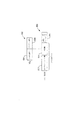
図1は、本発明の同位アーキテクチャの概要である。このアーキテクチャは、一つ以上のコンピューティング資源102と、一つ以上の相互接続ファブリック106と通信路108とを介してコンピューティング資源102に通信可能に連結された一つ以上の記憶資源104とを含む。ファブリック106は、すべてのノードと記憶装置との間の通信手段を提供し、こうしてコンピューティング資源102と記憶資源104との間の一様な同位アクセスを実現する。
【0015】
図1に示すアーキテクチャでは、記憶装置はもはや、現在のノード中心のアーキテクチャのように単一のセットのノードに縛られることはなく、またどのノードもすべての記憶装置と通信できる。これは、物理的システム・トポロジーが記憶装置とノード間の通信を制限していて、異なる仕事負荷に対応するためにはしばしば異なるトポロジーが必要になった今日のマルチノード・システムとは対照的である。図1に示すアーキテクチャは、システム・トポロジーの広いスペクトルをサポートする単一の物理アーキテクチャを提供することによって、アプリケーション・ソフトウエアの通信パターンがいかなる時点でもシステムのトポロジーを決定できるようにしており、技術進歩の不均一さに対応している。ファブリック106によって与えられる分離は、主要なシステム・コンポーネントの各々について極めて僅かずつの拡張を可能にする。
【0016】
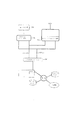
図2は、本発明の同位アーキテクチャの更に詳細な説明を示す。コンピューティング資源102は、一つ以上のコンピューティング・ノード200によって定義されており、一つ以上のプロセッサを有する各々のコンピューティング・ノードはオペレーティング・システム202の制御下で一つ以上のアプリケーション204を実現している。コンピューティング・ノード200には、テープ駆動機構、プリンタ、その他のネットワークといった周辺装置208が機能的に連結されている。またコンピューティング・ノード200には、オペレーティング・システム202を含む命令とか、アプリケーション204、その他の情報といったコンピューティング・ノード固有の情報を記憶するハードディスクといったローカルの記憶装置210が機能的に連結されている。アプリケーションの命令は、分散処理方式で、二つ以上のコンピューティング・ノード200に亘って格納、および/または実行できるようになっている。一実施例では、プロセッサ216は、INTEL P6といった既製品で商業的に入手可能な多目的プロセッサと、関連のメモリと入出力エレメントとを含む。
【0017】
記憶資源104は、クリーク226によって画定されており、これらクリークの各々は、第1の入出力ノードあるいはION212と第2の入出力ノードあるいはION214とを含み、その各々はシステム相互接続部228によって相互接続ファブリック106の各々と機能的に連結されている。第1のION212と第2のION214は、JBOD筐体222に関連する一つ以上の記憶ディスク224(「just a bunch disksほんの一束のディスク)」あるいはJBODとして知られている)に機能的に連結されている。
【0018】
図2は、典型的な2対1のION212対コンピューティング・ノード比を持つ中規模システムを示す。本発明のクリーク226は、三つ以上のION214を用いて、あるいは記憶ノードの可用性に幾分かの損失はあるが単一のION212を用いて実現することもできる。クリーク226の個数は、複数のION212の間で共用ハードウエアが存在しないので、純粋にソフトウエアの問題である。対になったION212は、「ダイポール」と呼ばれることもある。
【0019】
本発明はまた、コンピューティング・ノード200とION212と相互接続ファブリック106とにインタフェース接続する管理コンポーネントまたはシステム管理ソフトウエア230も含む。
【0020】
ION212とJBOD212との間の接続は、ここでは単純化された形で示してある。実際の接続は、図示の構成における記憶ディスク224の各ランク(行、ここでは4行)に対してファイバ・チャネル・ケーブルを使っている。実際には、各ION212は、図示の実施例に示す20個よりもむしろ40個と80個の間の記憶ディスク224を管理することになるであろう。
【0021】
ION(記憶ノード)
内部アーキテクチャ
ハードウエア・アーキテクチャ
図3は、ION212の構成と、JBOD222に対するそのインタフェースとに関して更に詳細を示す図である。各ION212は、JBOD相互接続部216を介してJBOD222アレー内の各記憶ディスク224に通信可能に連結するための入出力接続モジュール302と、ION212機能を実行してここに述べるION物理ディスク・ドライバ500を実現するCPUおよびメモリ304と、ION212操作をサポートするために電力を供給する電力モジュール306とを含む。
【0022】
JBOD図4は、JBOD筐体222に関して更に詳細を示す図である。監視あるいは制御が可能であるJBOD筐体222内のすべてのコンポーネントは、エレメント402〜424と呼ばれる。所定のJBOD筐体のためのすべてのエレメント402〜424は、構成ページ符号を持った受信診断結果コマンドを介して返される。ION212は、これらのエレメントを番号付けしているこのエレメント順序付けリストを使用する。記載の第1のエレメント402はエレメント0であり、第2のエレメント404はエレメント1であり、以下同様である。これらのエレメント番号は、コンポーネントをアドレス指定するためにここに記載の管理サービス層706によって使われるLUN−Cを作成するときに使われる。
【0023】
【表1】

【0024】
入出力インタフェース・ドライバ・アーキテクチャ
図5は、ION212のための「SCSIドライバ」として機能するION物理ディスク・ドライバ500を含めて、ION212入出力アーキテクチャを示す図である。ION物理ディスク・ドライバ500は、RAID(redumdant array of inexpensive disks:低価格ディスクの冗長アレー)ソフトウエア・ドライバまたはシステム管理ソフトウエア230内の管理ユーティリティからの入出力要求を取り入れる責任を持っており、そしてJBOD相互接続部216の装置側の装置上でその要求を実行する。
【0025】
本発明の物理ディスク・ドライバ500は、三つの主要コンポーネント:ハイレベル・ドライバ(HLD)502とローレベル・ドライバ506とを含む。HLD502は、共通部503と装置固有のハイレベル部504とローレベル・ドライバ506とを含む。共通部502と装置固有ハイレベル・ドライバ504は、アダプタ独立であって、新しいアダプタ型のために修正を必要としない。ファイバ・チャネル・インタフェース(FCI)ローレベル・ドライバ506は、ファイバ・チャネル・アダプタをサポートしており、したがってアダプタ固有よりもむしろプロトコル固有である。
【0026】
FCIローレベル・ドライバ506は、SCSI要求をFCPフレームに変換し、またログイン(Login)と処理ログイン(Process Login)のようなファイバ・チャネル共通サービスを取り扱う。FCIローレベル・ドライバ506には、ファイバ・チャネル・プロトコル処理をアダプタ固有ルーチンから分割するハードウエア・インタフェース・モジュール(HIM)インタフェース508が機能的に連結されている。上述のコンポーネントの更に詳細な説明は、以下に示す。
【0027】
ハイレベル・ドライバ
ハイレベル・ドライバ(HLD)502は、どのような型の装置がアクセスされている場合でも、ION212に対するすべての要求についての入口点である。ある装置が開かれると、HLD502はコマンド・ページをその装置に結び付ける。これらの業者固有のコマンド・ページは、固有のSCSI機能のためにSCSIコマンド記述子ブロックがどのように構築されるべきかを指示する。コマンド・ページは、あるSCSI機能をSCSI仕様の指定とは異なるように取り扱う装置をドライバが容易にサポートできるようにする。
【0028】
共通(装置固有でない)部
HLD502の共通部は、下記の入口点を含む。
・cs−init :ドライバ構造を初期化して資源を割り当てる。
・cs−open :装置を使用可能にする。
・cs−close:入出力を完了して装置をサービスから削除する。
・cs−strategy:装置の読み/書き入力を阻止する(Buf−t interface)。
・cs−intr :ハードウエア割込みをサービスする。
【0029】
これらのルーチンは、すべての装置の型について同じ機能を実行する。これらのルーチンの大部分は、装置の型(ディスク、テープ、worm(追記型)、CD ROM等)によって指標付けされたスイッチ(切替え)表によっていかなる装置固有の要件でも取り扱う装置固有ルーチンを呼び出す。
【0030】
この cs−open機能は、その装置が存在しており、そこで実行されるべき入出力操作の準備ができていることを保証する。現在のシステム・アーキテクチャとは異なり、共通部503は、オペレーティング・システム(OS)の初期化期間中に既知の装置の表を作成することはない。その代わりにドライバ共通部503は自己構成を行う。すなわちドライバ共通部503は、その装置の初期オープン時に装置の状態を決定する。これは、ドライバ共通部503がOS202の初期化段階後にオンラインになった可能性のある装置を「見る」ことができるようにする。
【0031】
初期オープン期間中、SCSI装置は、目標装置にSCSI問合せコマンドを発行することによってコマンド・ページに結合される。もし装置が肯定的に応答すれば、その応答データ(業者ID、製品ID、ファームウエア改訂レベルといった情報を含む)がSCSI構成モジュール516内の既知装置表と比較される。もし一致があれば、その装置は、その表の項目に指定されたコマンド・ページに明示的に結合される。もし一致がなければ、その装置は、一般CCS(Common Comand Set:共通コマンド・セット)またはその応答データ・フォーマットに基づくSCSI・IIコマンド・ページに暗示的に結合される。
【0032】
ドライバ共通部503は、ローレベル・ドライバ506によって使われるルーチンと、資源を割り当て、分散・収集操作のためのDMAリストを作成し、SCSI操作を完了させるコマンド・ページ機能とを含む。
【0033】
すべてのFCIローレベル・ドライバ506ルーチンは、ドライバ共通部503から呼び出される。ドライバ共通部503は、ハードウエアを設定して動作を開始させるためにハードウエア・インタフェース・モジュール(HIM)508内の適当なローレベル・ドライバ(LLD)ルーチンを呼び出すことによってSCSI動作を実際に起動する唯一の層である。LLDルーチンはまた、SCSI構成モジュール516から構成時に割り当てられた、ドライバIDによって指標付けされたスイッチ表を介してアクセスされる。
【0034】
装置固有部
共通部502と装置固有ルーチン504との間のインタフェースは、共通部へのインタフェースと似ており、また csxx−init、csxx−open、csxx−close、csxx−strategyというコマンドを含んでいる。“xx” という記号は、記憶装置の型(例えばディスクについては“dk”あるいはテープについては“tp”)を示す。これらのルーチンは、いかなる装置固有要件でも取り扱う。例えばもし装置がディスクであったとすれば、csdk−openはそのディスクの固有領域から区分表情報を読み取らなければならず、またcsdk−strategyはその区分表情報を使って、ブロックが禁止区域にあるかどうかを判定しなければならない。(区分表は各固有の物理ディスク毎に論理ディスクから物理ディスクへのディスク・ブロックのマッピングを定義している。)
【0035】
ハイレベル・ドライバの誤り/失敗の処理
誤り処理
再試行
HLD502の最も一般的な回復方法は、失敗した入出力操作を再試行することによっている。所定のコマンド型に関する再試行の回数は、コマンド・ページによって指定される。例えば読取りあるいは書込みコマンドは非常に重要であると見なされるので、それらに関連のコマンド・ページは、再試行回数を3と設定することもできる。問合せコマンドは重要とは見なされないが、一日の初めの操作の時に、一定の再試行回数ではシステムの性能低下を招くので、その試行回数はゼロにされることもある。
【0036】
初めに要求が発行されると、その再試行回数はゼロに設定される。要求が失敗して回復手順が再試行されることになる度ごとに、再試行回数は増やされる。もし再試行回数がコマンド・ページで指定された最大試行回数より大きくなれば、その入出力操作は失敗となり、要求者にはメッセージが返送される。そうでなければ、それは再発行される。このルールの唯一の例外は、ユニット・アテンションに関するものであって、これは一般には誤りというよりはイベント通知である。もしあるコマンドに関してユニット・アテンションが受け取られ、その最大再試行回数がゼロか1に設定されていれば、ハイレベル・ドライバ502は、この特定の入出力のための最大再試行を2に設定する。これは、ユニット・アテンション状態のために早まって失敗と送り返される入出力を防止することになる。
【0037】
遅延された再試行は、その再試行が所定の時間の間は、待ち行列に再配置されないということを除いて、上述の再試行手順と同じに扱われる。
【0038】
失敗したScsi−ops
FCIローレベル・ドライバ506に発行されるScsi−opは、幾つかの状況によって失敗することがある。表2は、FCIローレベル・ドライバ506がHLD402に返すことのできる、起こり得る失敗の型を下に示す。
【0039】
【表2】
ローレベル・ドライバの誤り条件
資源不足誤りは、要求時に所望の資源が利用可能でないときに発生する。一般にこれらの資源は、システム・メモリとドライバ構成メモリである。
【0040】
システム・メモリ不足処理は、セマフォ・ブロッキング(信号阻止)によって遂行される。メモリ資源をブロックするスレッド(プロセスの集まり)は、新しい入出力が発行されるのを防止するであろう。このスレッドは、入出力完了がメモリを解放するまでブロックされたままになっているであろう。
【0041】
ドライバ構成資源は、Scsi−opおよび入出力ベクトル(IOV)リスト・プールに関連している。IOVリストは、ディスクとの間でやり取りされるメモリの開始値と長さ値のリストである。これらのメモリ・プールは、プールのサイズを指定するために調整可能なパラメータを使うことによって一日の初めに初期化される。もしScsi−opまたはIOVプールが空であれば、新しい入出力が入ってこれらのプールを大きくする結果になるであろう。いずれかのプールを大きくするために一時に1ページ(4096バイト)のメモリが割り当てられる。その新しいページからすべてのScsi−opsまたはIOVが解放されるまで、そのページは解放されない。もしION212がScsi−opsに関するページまたはページを絶えず割り当てたり解放したりしているならば、関連するパラメータを調整することが望ましいかもしれない。
【0042】
すべての資源不足処理はイベントを通じてログ(記録)される。
【0043】
一日の初めの処理
一日の初めにHLD502は、その必要な構成とプールとを初期化し、そしてアダプタ固有のドライバとハードウエアとを初期化するための呼出しを行う。一日の初め処理は、(1)Scsi−Opプールを割り当てることと、(2)IOVプールを割り当てることと、(3)ファイバ・チャネル構成とハードウエアとを初期化するためにFCIhw−init()への呼出しを行うことと、(4)割込みサービス・ルーチンcs−initr()を適当な割込みベクトルに結合することとを行うcs−init()への呼出しによって開始される。
【0044】
失敗の処理
ION212ダイポールの二つの半分は、共通セットのディスク装置に付加される。ダイポール226内のION212、214は両者とも何時でも所定のときにすべての装置にアクセスできなくてはならない。HLD502から見て、失敗のために特別の処理はない。
【0045】
コマンド・ページ
本発明のION212は、SCSIコマンドの実際のビルディングから共通部と装置固有部とを抽出するコマンド・ページ方式を使用する。コマンド・ページは、各関数がSCSIコマンド(例えばSCSI−2−Test−Unit−Ready)を表す関数へのポインタのリストである。上述のように、ある特定のコマンド・ページは、ある装置の初期オープンまたはアクセス時にその装置に結合される。すべての業者独自のそして柔軟性のないSCSI装置の癖は、その装置固有のコマンド・ページを介して参照される関数によって管理される。一般的なシステムは、柔軟性のないSCSI装置あるいは業者独自のSCSIコマンドの統合を可能にするために、コマンド・コントロール・セット(CCS)と、SCSI・IおよびSCSI・IIページと、業者独自ページとを一緒に付けて出荷される。
【0046】
コマンド・ページ関数は、装置共通部503と装置固有部504とFCIローレベル・ドライバ506(要求センス)とから仮想装置(Virtual DEVice(VDEV))インタフェースと呼ばれるインタフェースを介して呼び出される。これらのレベルでは、ソフトウエアは、装置がどのSCSI方言を使うかを気にせずに、単に意図した関数を装置が実行することを気にかける。
【0047】
各コマンド・ページ関数は、SCSIコマンドを構築して、必要ならば、直接メモリ・アクセス(DMA)データ転送のためにメモリを割り当てる。それからこの関数は、ドライバ共通部503に制御を返す。その後、ドライバ共通部503は、待ち行列上にSCSI操作を配置し(必要であればここで分類が行われる)、FCIローレベル・ドライバ506の起動ルーチンを呼び出すことによってそのSCSIコマンドを実行する。そのコマンドが実行されたのち、もしそのコマンド・ページ関数のなかに「割込み時呼出し:Call On Interrupt(COI)」ルーチンが存在すれば、完了後のコマンドのデータ/情報をそのドライバのドライバ共通部503が吟味する前に、COIが呼び出されるであろう。
【0048】
返されたデータ/情報をマッサージすることによってCOIは、非標準のSCSIデータ/情報を標準のSCSIデータ/情報に変換することができる。例えばもし装置の問合せデータがバイト8の代わりにバイト12で始まる業者IDを含んでいるならば、問合せに関するコマンド・ページ関数は、業者IDを、返却された問合せデータのバイト8にシフトするCOIを含むことになるであろう。ドライバ共通部503は常に、バイト8で始まる業者ID情報を抽出するであろうから非標準装置について知る必要がなくなる。
【0049】
JBODおよびSCSI構成モジュール
RAID制御部の重要な機能は、損失しないようにデータを確保することである。この機能を実行するためにRAIDソフトウエアは、ディスク装置が何処に常駐していてその配線がそれをどのように接続しているかを物理的に知らなくてはならない。それ故、RAID制御部技術実現の重要な要件は、記憶装置の構成を制御する能力である。JBODおよびSCSI構成モジュール516のJBOD部には、ION212のための静的なJBOD構成を定義することが課せられている。JBODおよびSCSI構成モジュール516によって記述される構成情報は、表3に示す。
【0050】
【表3】
【0051】
ファイバ・チャネル・インタフェース(FCI)ローレベル・ドライバ
FCIローレベル・ドライバ506は、ハイレベル・ドライバ502用のSCSIインタフェースを管理する。ドライバ共通部503とFCIローレベル・ドライバ506との間のインタフェースは、下記のルーチンを含んでおり、ここで“xx” の表示はFCIローレベル・ドライバ506が制御するハードウエアに関する一意の識別子である(例えばFCIhw−init)。
・xxhw−init ハードウエアを初期化する。
・xxhw−open ホスト・アダプタの現在状態を決定する。
・xxhw−config ホスト・アダプタの構成情報(SCSI ID等)を設定する。
・xxhw−start 可能であれば、SCSI操作を起動する。
・xxhw−intr すべてのSCSI割込みを処理する。
【0052】
ローレベル・ドライバは、装置の仕様について知ることも気にかけることもない純粋なSCSIドライバであるが、その代わりに単に上位レベルからのSCSIコマンドの導管である。この層には、割込みサービス・ルーチンとハードウエア初期化ルーチンとマッピングおよびアドレス変換ルーチンと誤り回復ルーチンとが常駐している。更に同じシステム内に複数の型のローレベル・ドライバが共存できる。ハードウエア制御層とドライバの残りの部分との間のこの分割は、同じハイレベル・ドライバが異なるマシン上で走行することを可能にしている。
【0053】
FCIモジュールの基本機能は、(1)SCSIハイレベル・ドライバ(SHLD)にインタフェース接続してSCSI OpをFCI作業オブジェクト構成(入出力ブロック(IOB))に変換することと、(2)異なるHIM508を介して新しいファイバ・チャネル・アダプタのサポートを容易にするために共通インタフェースを提供することと、(3)いかなるFC−4プロトコル層(図示の実施例のファイバ・チャネル・プロトコル(FCP))によって使うことのできるFC−3共通サービスを提供することと、(4)HIM508またはハードウエアが応答しない場合にHIMに送られた非同期コマンド(例えばFCPコマンド、FC−3コマンド、LIPコマンド)を保護するタイマー・サービスを提供することと、(5)(a)入出力要求ブロック(IOB)と(b)ベクトル表と(c)HIM508資源(例えばホスト・アダプタ・メモリ、DMAチャネル、入出力ポート、スクラッチ・メモリ)とを含むファイバ・チャネル・ドライバ全体(FCIとHIM)のための資源を管理することと、(6)ファイバ・チャネル調停ループ使用(対ファイバ・チャネル・ファブリック)を最適化することとである。
【0054】
FCIローレベル・ドライバ506用の重要なデータ構造のリストを下記の表4に示す。
【0055】
【表4】
FC基本データ構造
誤り処理
FCIローレベル・ドライバ506が処理する誤りは、ファイバ・チャネルおよび/またはFCI自身に固有の誤りである傾向がある。
【0057】
多段階誤り処理
FCIローレベル・ドライバ506は、ある幾つかの誤りを多段階誤り処理によって処理する。これは、誤り処理手法が誤りの型にとって最適化されることを可能にする。例えば、もしより危険の少ない手順が使われて、効果がない場合には、更に激しい誤り処理対策がとられることがある。
【0058】
失敗したIOB
すべての入出力要求は、入出力要求ブロックを介してHIM508に送られる。下記は、HIM508が送り返すことのできる、起こり得る誤りである。
【0059】
【表5】
HIM誤り条件
資源不足
FCIローレベル・ドライバ506は、IOB用の資源プールとベクトル表とを管理する。これらのプールのサイズはION212構成向けに調整されるであろうから、これらの資源が枯渇することはなく、単純な回復手順が実現される。
【0061】
もしIOBまたはベクトル表を求める要求が行われてその要求を満足させるために十分な資源がない場合には、その入出力は待ち行列に戻されて入出力を再起動させるためのタイマーがセットされる。資源不足の発生はログに記録される。
【0062】
一日の初め処理
一日の初めにハイレベル・ドライバ502は、サポートされている各ローレベル・ドライバ(FCIローレベル・ドライバ506を含む)に呼出しを行う。FCIローレベル・ドライバ506の一日の初め処理は、下記の操作を実行するFCIhw−init()ルーチンを呼び出すことから始まる。
【0063】
先ず、特定のPCIバスと装置のためにHIM−FindController()関数が呼び出される。これは、あるバージョンのFindController()を呼び出す。JBODおよびSCSI構成モジュール516は、探索すべきPCIバスと装置とを指定する。次ぎに、もしアダプタ(ADAPTECから使用可能なアダプタのような)が見つかれば、そのアダプタにHCBが割り当てられて初期化される。それからスクラッチ・メモリ、メモリ・マップされた入出力、DMAチャネルといったそのアダプタ固有の資源を取得するために、HIM−GetConfiguration()が呼び出される。次ぎに、資源が割り当てられて初期化され、ADAPTEC HIMとハードウエアとを初期化するために HIM−Initialize()が呼び出される。最後にIOBとベクトル表とが割り当てられて初期化される。
【0064】
失敗処理
ION212ダイポールの二つの半分は、共通セットのディスク装置に取り付けられる。両方のION212は、何時でも所定のときにすべての装置にアクセスできなくてはならない。FCIローレベル・ドライバ506から見て、失敗に関する特別の処理はない。
【0065】
ハードウエア・インタフェース・モジュール(HIM)
ハードウエア・インタフェース・モジュール(HIM)508は、ADAPTECのSlimHIM509にインタフェース接続するように設計されている。HIMモジュール508は、FCIローレベル・ドライバ506からの要求をSlimHIM509が理解できてハードウエアに発行できる要求に変換するという主要な責任を持っている。これは、入出力ブロック(IOB)要求を取り入れることと、そのIOB要求をSlimHIM509によって理解される、それに対応する転送制御ブロック(TCB)要求に変換することとを含んでいる。
【0066】
HIM508の基本機能は、(1)アダプタに対して、Find(見つける)、Configure(構成する)、Initialize(初期化する)、SendI/O(入出力を送る)を行うハードウエア固有の関数へのローレベル・アプリケーション・プログラム・インタフェース(API)を定義することと、(2)入出力ブロック(IOB)をSlimHIM/ハードウエアが理解できるTCB要求(例えばFCプリミティブTCB、FC拡張リンク・サービス(ELS)TCB、SCSI−FCP操作TCB)に変換するためにFCIローレベル・ドライバ506にインタフェース接続することと、(3)SlimHIMに発行されたコマンドの引渡しと完了とを追跡することと、(4)SlimHIMからの割込みとイベント情報とを解釈して、FCIローレベル・ドライバ506と共同で適当な割込み処理および/または誤り回復を起動することとである。TCBのデータ構造は下記の表6に示す。
【0067】
【表6】
基本的なHIM構造
一日の初め処理
HIM508は、一日の初めに使われる3個の入口点を定義する。第1の入口点は、HIM−FindAdapterであって、これはFCIhw−init()によって呼び出され、PCI BIOSルーチンを使って所定のPCIバスおよび装置上にアダプタが常駐しているかどうかを決定する。そのアダプタについてのPCI業者・製品IDは、そのアダプタが存在するかどうかを決定するために使われる。
【0069】
第2の入口点は、HIM−GetConfigurationであって、これはアダプタが存在する場合にFCIhw−init()によって呼び出され、与えられたHCBの中に資源要件を入れる。ADAPTECアダプタについてこれらの資源は、IRQとスクラッチとTCBメモリとを含む。この情報は、SlimHIM509に呼出しを行うことによって求められる。
【0070】
第3の入口点は、HIM−Initializeであって、これは資源が割り当てられて初期化された後にFCIhw−init()によって呼び出され、TCBメモリ・プールを初期化し、SlimHIMを呼出してスクラッチ・メモリとTCBとハードウエアとを初期化する。
【0071】
失敗処理
ION216ダイポールの二つの半分は、共通セットのディスク装置に取り付けられる。ION212、214の両者は、何時でも所定のときにすべての装置にアクセスできなくてはならない。HIM509から見て、失敗に関する特別の処理はない。
【0072】
AIC−1160 SlimHIM
SlimHIM509モジュールは、アダプタのハードウエア概念を与えるという全体的な目的を持っている(図示の実施例ではADAPTEC AIC−1160)。このSlimHIM509は、ファイバ・チャネル要求をAIC−1160アダプタに移送し、割込みをサービスし、SlimHIM509インタフェースを介してHIMモジュールに状態を報告するという主要な役割を持っている。
【0073】
SlimHIM509はまた、AIC−1160ハードウエアの制御を担っており、これを初期化し、ファームウエアをロードし、実行時動作を起動し、AIC−1160の誤りの場合にAIC−1160ハードウエアの制御を行う。
【0074】
外部インタフェースとプロトコル
ION物理ディスク・ドライバ・サブシステム500のすべての要求は、共通のハイレベル・ドライバ502を介して行われる。
【0075】
Initialization(cs−init)
このサブシステムへの単一の呼出しは、入出力用に装置を準備するために必要となるすべての初期化を実行する。サブシステム初期化期間中にすべての装置あるいはアダプタハードウエアと同じく、すべてのドライバ構造が割り当てられて初期化される。
【0076】
Open/Close(cs−open/cs−close)
オープン/クローズ(Open/Close)インタフェース510は、装置へのアクセスに必要な構造を初期化して分解する。このインタフェース510は、すべての「オープン」と「クローズ」とが暗示的に層状にされているという理由から一般のオープン/クローズ・ルーチンとは異なっている。したがって入出力物理インタフェース・ドライバ500が受け取るすべての「オープン」は、受信されて関連付けられた「クローズ」を伴っていなければならず、また装置関連構造は、すべての「オープン」が「クローズ」されるまで解放されない。オープン/クローズ・インタフェース510は、「オープン」または「クローズ」の返却がその要求の完了を示すと言うことにおいて同期している。
【0077】
Buf−t(cs−strategy)
Buf−tインタフェース512は、装置への論理ブロック読取り・書込み要求の発行を可能にする。要求者は、入出力を記述するBuf−t構造を伝える。装置ID、論理ブロック・アドレス、データ・アドレス、入出力の型(読取り/書込み)、呼戻しルーチンといった属性は、Buf−tによって記述される。要求が完了すると、要求者による呼戻しによって指定された関数が呼び出される。Buf−tインタフェース512は、非同期インタフェースである。要求者への関数の返却は、その要求が完了したことを示すわけではない。関数が返されるとき、入出力はその装置上で実行中であってもなくてもよい。要求は、実行されるのを待つ待ち行列上にあってもよい。この要求は、呼戻し関数が呼び出されるまでは完了しない。
【0078】
SCSILib
SCSILib514は、装置に送るべき通常の読取り・書込み以外のSCSIコマンド記述子ブロック(CDB)を可能にするインタフェースを提供する。このインタフェースによって、ディスクを回転させたり停止させるために装置起動・停止といった要求が使われ、また密閉装置を監視したり制御するためにSend、Receive(送信、受信)診断が使われるであろう。すべてのSCSILibルーチンは、同期している。呼び出された関数の返却は、要求の完了を示す。
【0079】
Interrupts(cs−intr)
ION物理ディスク・ドライバ500は、すべてのSCSIおよびファイバ・チャネル・アダプタの割込みのための中心的なディスパッチャである。一実施例ではフロントエンド/バックエンド割込み方式が利用される。このような場合に割込みが行われると、フロントエンド割込みサービス・ルーチンが呼び出される。フロントエンドは、割込みスタックから実行し、また割込み源を除去することと、更に割込みを発生させないようにアダプタを切り離すことと、バックエンド割込みサービス・ルーチンをスケジューリングすることとに責任を持っている。バックエンドは、実際に割込み(アダプタ割込みの切り離しとバックエンド・タスクの開始との間に発生したかもしれなかった他のいかなる割込みとも一緒に)を処理する優先度の高いタスクとして実行する。
【0080】
ION機能
ION212は、5個の主要な機能を実行する。これらの機能には下記のものが含まれる。
【0081】
記憶装置の命名と投影:記憶ディスク224上に記憶された記憶資源オブジェクトのイメージをコンピューティング・ノード200に投影することによって、一様で一貫性のある記憶装置の命名を提供するためにコンピューティング・ノード200と調和的動作をする。
【0082】
ディスク管理:ION212と機能的に連結された記憶ディスク駆動機構224を用いてデータ分散およびデータ冗長の技術を実現する。
【0083】
記憶装置管理:コンピューティング・ノード200からの入出力要求の処理、性能上の機器構成およびイベント分散を含めて記憶装置の設定、データ移動などを処理するためのもの。
【0084】
キャッシュ管理:アプリケーション・ヒント・プリフェッチといったキャッシュ・フル操作を含む読み・書きデータのキャッシングのためのもの。
【0085】
相互接続管理:性能を最適化するためにコンピューティング・ノード200との間のデータの流れを制御し、要求の経路指定を制御し、またしたがってダイポール226内の二つのION212の間での記憶の分配を制御する。
【0086】
記憶装置の命名および投影
ION212は、記憶ディスク224上に記憶された記憶資源オブジェクトのイメージをコンピューティング・ノード200に投影する。この機能の重要な役割は、ION212によって管理される各記憶資源(仮想ファブリック・ディスクを含む)に関して、グローバルに一意の名前、ファブリック独自のID、あるいはボリューム・セット識別子(VSI)602の作成と割り当てである。
【0087】
図6は、VSIの構造と内容および関連データを示す図である。VSI602が一意であって競合しないことは重要であるから、各ION212は、そのION212によってローカルに管理される記憶資源に関してグローバルに一意の名前を作成して割り当てることに責任があり、また記憶資源オブジェクトを記憶する記憶資源を管理するそのION212だけがその記憶資源に関してVSI602を割り当てることが許される。常駐記憶資源を現に管理しているION212だけはVSI602を作成して割り当てることができるが、他のION212は、その後にそれらの記憶資源の記憶と検索とを管理することができる。これは、もしION割り当てのVSI602が他のIONによって管理される記憶資源に後で移されても、ある特定のデータ・オブジェクトについてのVSI602は変更する必要がないからである。
【0088】
VSI602は、ION識別子604とシーケンス番号506という二つの部分を含む64ビットの数として実現される。ION識別子604は、各ION212に割り当てられるグローバルに一意の識別番号である。グローバルに一意のION識別子604を得る一つの手法は、しばしばリアルタイム・クロック・チップに格納される電子的に読取り可能なマザーボード通し番号を使うことである。この通し番号は、ただ一つのマザーボードに割り当てられるだけであるから一意である。ION識別子604がグローバルに一意の番号であるから、各ION212は、ローカルにだけ一意であるシーケンス番号を割り当てることができ、また更にグローバルに一意のVSI602を作成することができる。
【0089】
VSI602がION212上の記憶資源に結合されたのちに、そのION212は、その記憶資源104へのアクセスを可能にするファブリック上のすべてのノードに対して同報メッセージを介してVSI602を移出する。この処理は、本書のION名前移出セクションで更に論ずる。
【0090】
それからコンピューティング・ノード200ソフトウエアは、移出されたVSI602を使って、他のいかなるローカルに付加された記憶装置とは区別がつかないということにおいて意味的にトランスペアレントであるその記憶資源についてのローカルの入口点を作成する。例えばもしコンピューティング・ノードのオペレーティング・システム202がUNIXであったとすると、ブロック装置入口点と裸装置入口点の両者とも、周辺装置108またはディスク210といったローカルに付加された装置に類似の装置ディレクトリ内に作成される。他のオペレーティング・システム202についても同様な意味的に同等なものがついてくる。異なるオペレーティング・システム202を走行させるコンピューティング・ノード200の間では、異種コンピューティング環境を最も良くサポートするためにルート名の整合性が維持される。
【0091】
コンピューティング・ノード200内のローカルの入口点は、移出された記憶資源104の現在の可用性を追跡するためにION212によって動的に更新される。VSI602は、移入された記憶資源について装置入口点名を作成するためにコンピューティング・ノード200上で走行するOS依存のアルゴリズムによって使われる。この手法は、共通のオペレーティング・システムを共用するノード間での名前の整合性を保証する。これは、各コンピューティング・ノード200上のグローバルに命名された記憶資源のためのローカルな入口点を動的に(静的の代わりに)作成することによって異種コンピューティング環境をサポートするために、システムがルート名の整合性を維持することを可能にしている。
【0092】
上述のように記憶資源104に関するVSI604の作成の詳細は、記憶資源104を移出しているION212によって直接制御される。コンピューティング・ノード200間の潜在的なオペレーティング・システム104の違いを説明するために、1個以上の記述的ヘッダが各VSI602に結合されて、ION212上のVSI602と一緒に格納される。各々のVSI602記述子608は、特定のVSI602に関するコンピューティング・ノード200上の装置入口点の矛盾のない(名前と動作上の意味の両者がコンピューティング・ノード200全体に亘って同じである)作成のために必要な十分なOS202依存性のデータを格納するためのオペレーティング・システム(OS)依存データ・セクション610を含んでいる。
【0093】
このOS依存データ610は、例えばローカルなアクセス権612を記述するデータと所有権情報614とを含んでいる。VSI602がION212によって確立され、コンピューティング・ノード200によって移出された後で、しかしVSI602に関連したその記憶資源104のための入口点が作成されるよりは前に、適当なOS固有データ610は、ION212によってコンピューティング・ノード200に送られる。一つのVSI602当たり多数の記述的ヘッダは、異なるOS(各OSはそれ自身の記述子ヘッダーを持っている)を走らせる多数のコンピューティング・ノード200のサポートと、異なるコンピューティング・ノード200グループ間でのばらばらのアクセス権のサポートとの両方を同時に可能にする。同じ記述子ヘッダを共用するコンピューティング・ノード200は、装置入口点の共通で矛盾のない作成を共用する。このようにして名前と動作上の意味の両者とも、共通セットのアクセス権を共有するすべてのコンピューティング・ノード200上で整合性を維持することができる。
【0094】
VSI記述子608はまた、別名フィールド616を含んでおり、これは人間が読取れるVSI602名をコンピューティング・ノード200上に表示するために使用できる。例えばもしVSI1984の別名が「soma」であれば、コンピューティング・ノード200は、1984と「soma」の両方に関するディレクトリ・エントリを持つことになるであろう。VSI記述子608はION212上のVSI602と一緒に格納されるので、VSI602を移入する各コンピューティング・ノード200上には同じ別名とローカル・アクセス権とが現れるであろう。
【0095】
前述のように本発明は、分散型割当て方式に適する命名手法を使用している。この手法では、名前はグローバルな一意性を保証するアルゴリズムにしたがってローカルに作成される。これの変形は、各システムごとに中心的な命名サーバが存在する、ローカルに集中化する手法を追求することもできようが、可用性と頑丈さとの要件からは純粋な分散型手法を重く見ている。上述のことを使って、本発明はグローバルな一意性を保証するローカルに実行可能なアルゴリズムを作成することができる。
【0096】
グローバルに整合性のある記憶システムを作成することは、コンピューティング・ノード200全体に亘って名前の整合性を保存するだけでなくサポートすることを更に必要とする。名前の整合性は、安全保護の問題であって、これは本発明では二つの形式を採る。第一は、ION212とコンピューティング・ノード200との間のインタフェースの安全保護であり、第二は、コンピューティング・ノード200内からの記憶の安全保護である。
【0097】
記憶の認証と認可
VSI602資源は、認証と認可という二つの異なる機構で保護されている。もしコンピューティング・ノード200がION212によって認証されれば、VSI名がそのコンピューティング・ノード200に移出される。移出されたVSI602は、コンピューティング・ノード200上に装置名として現れる。コンピューティング・ノード200上で走行するアプリケーション・スレッドは、この装置名で操作の実行を試みることができる。装置入口点のアクセス権とコンピューティング・ノード200のOS意味論とは、アプリケーション・スレッドがいかなる所定の認可でも実行するように権限付与されているかどうかを決定する。
【0098】
この認可の手法は、コンピューティング・ノード200の認可を、相互接続ファブリック106によってアクセス可能な何処にでも配置される記憶資源にまで拡張する。しかしながら本発明は、本発明においては記憶資源104がコンピューティング・ノード200によって直接的に管理されないということで、他のコンピュータ・アーキテクチャとは異なっている。この相違は、ローカルの認可データを単にファイル・システム・エンティティに結合することを実行できなくする。その代わりに本発明は、コンピューティング・ノード200認可方針データをION212のVSI602と結合させて、コンピューティング・ノード200とION212とがあるレベルの相互信頼を共有する二段階手法を用いる。ION212は、ある所定のVSI602への各コンピューティング・ノード200アクセスを認可するが、VSIによって指示されたデータに対する特定のアプリケーション・スレッドの認可の更なる改良は、このコンピューティング・ノード200の責任である。それからコンピューティング・ノード200は、ION212によって記憶された認可メタデータ内に含まれる方針を使って、記憶エンティティ104に関する認可方針を実行する。
【0099】
したがってコンピューティング・ノード200は、ION212を信頼してメタデータを保存することを要求され、またION212に対してはコンピューティング・ノード200を信頼してその認可を実行することを要求する。この手法の一つの利点は、ION212に対してメタデータを解釈する方法に関する知識を持つことを要求しないということである。したがってION212は、コンピューティング・ノード200によって使われている異なるオペレーティング・システム202によって課せられた異なる認可意味論によって課せられた特定の認可意味論を実行することから分離される。
【0100】
VSI602に関連するすべてのデータ(アクセス権を含めて)は、ION212に格納されるが、アクセス権データの内容を管理する責任はコンピューティング・ノード200に置かれている。特にION212によって移出されるVSI602のリストがコンピューティング・ノード200に送られると、ローカルな認可を実行するようにそのコンピューティング・ノード200によって要求されるOS固有データのすべては各VSI602に結合される。例えばUNIXを走行させるコンピューティング・ノード200は、名前とグループ名とユーザIDとモード・ビットとを、すなわちファイル・システムに装置入口ノードを作るために十分なデータを送られるであろう。
【0101】
コンピューティング・ノードのオペレーティング・システム202のそのクラスにとって固有の(あるいは正にそのコンピューティング・ノード200にとって固有の)VSI602の別の名前は、各VSI602と一緒に含まれる。記憶装置のアクセス権を変更するローカルのOS固有コマンドは、コンピューティング・ノード200ソフトウエアによって捕捉されてION212に送られるメッセージに変換される。このメッセージは、OSバージョンに固有のVSIアクセス権データを更新する。この変更が完了したときION212は、システム内でそのOSを使っているすべてのコンピューティング・ノード200にこの更新を送信する。
【0102】
コンピューティング・ノード(CN)200がオンラインになるとそれは、「自分はここにいます」というメッセージを各ION212に送信する。このメッセージは、このコンピューティング・ノード200を識別するディジタル署名を含んでいる。もしこのコンピューティング・ノード200がION212によって知られれば(ION212がコンピューティング・ノード200を認証すれば)、ION212は、そのコンピューティング・ノード200がアクセス権を有するすべてのVSI名を移出する。コンピューティング・ノード200は、VSI名のこれらのリストを使ってシステム記憶用のローカル・アクセス入口点を構築する。このコンピューティング・ノード200内で走行するアプリケーション204がローカル端点を参照すると、コンピューティング・ノード200はそのVSI602用のアクセス権記述データに関するあるメッセージを相互接続ファブリック106に亘って送信することによってION212に対して要求を行う。
【0103】
この要求メッセージは、要求しているコンピューティング・ノード200に関するディジタル署名を含んでいる。ION212は、このメッセージを受け取り、ディジタル署名を使って、応答時に送るべきVSIアクセス権の適当なセットを突き止め、要求中のコンピューティング・ノード200にそのデータを相互接続ファブリック106を介して送信する。ION212はコンピューティング・ノード200に送られたアクセス権を解釈しないで単にそのデータを送るだけである。コンピューティング・ノード200ソフトウエアは、このデータを使って、この主題の記憶オブジェクトのためのローカル入口点にローカルアクセス権の適当なセットを結合する。
【0104】
一セットのコンピューティング・ノード200は、同じディジタル署名を使うか、多数の異なる署名を同じセットのアクセス権に結合するかいずれかによってこの同じセットのアクセス権を共有できる。本発明は、コンピューティング・ノード200を識別するためと、どのセットのローカル認可データを使ってローカル入口点を作成するかを指定するためとの両方に認証を使う。認可データは、VSI602が最初にアプリケーションによって参照されるときにコンピューティング・ノードに引き出されるだけである。この「必要時に引く」モデルは、非常に大きなシステム上で大量のアクセス権メタデータを移動させることの運転開始コストを回避する。
【0105】
もしコンピューティング・ノード200が認証に失敗するならば、ION212はVSI602名を持たないメッセージを送り返し、そして認証失敗フラグがセットされる。コンピューティング・ノード200は、そのION212からのVSI装置名なしで黙って続行することができ、またシステム管理者の希望によってその認証失敗を報告することもできる。もちろん認証に成功してもVSI装置名をコンピューティング・ノードに送らないことにしてもよい。
【0106】
起動時の競合解消
ION212は起動するとき、VSI602を相互接続ファブリック106に移出しようとする。このような場合、システムのデータ完全性は新しいION212による破壊から保護されなくてはならない。これを達成するために新しいION212は、記憶の移出が許される前に検査される。これは次のように遂行される。最初にION212は、そのローカル記憶を調べて、移出可能なVSI602のリストを作成する。VSI602メタデータは、VSIの世代番号または変更番号を含む。このVSI変更番号は、そのVSI602に関連した主な状態変更があるときは何時でも(VSIが、あるネットワークにうまく移出されたときなど)増やされる。コンピューティング・ノード200とION212とを含めて、VSI競合検出に関与するすべてのノードは、移出されたVSIの履歴とそれらの変更番号とをメモリ内に保持する。
【0107】
相互接続ファブリック106上のすべてのノードは、移出されたVSI602をVSI競合に関して絶えず監視することが必要とされる。最初にVSI変更番号は(記憶領域が最初に生成されたとき)ゼロにセットされる。変更番号は、移出された前回よりも低い変更番号を持った移出VSI602は、真のVSI602に関連したION212が使われなくなった場合でも偽のVSIであると想定されることがあり得るると言うことにおいて、競合解消基準を提供する。真のVSI602に関連した変更番号よりも高い変更番号を有するION212に付加された偽のVSI602は、真のVSI602上で既に入出力が実行されてしまったのでなければ、真のVSI512と見なされる。相互接続ファブリック106に新たに導入されたION212は、0から始まるその変更番号を持つ必要がある。
【0108】
ION212は、システムに入りたいと公表したのちに、VSI602とそれ関連の変更番号とのそのリストを送信する。その他のすべてのION212とコンピューティング・ノード200は、このリストを取得してから、VSI602リストを移出するためにION212の妥当性を検査する。
【0109】
同じVSI602を現在移出中の他のIONは、妥当であると想定され、競合している特定のVSIの移出を許可しないというメッセージを新しいION512に送る。もし新しいION512がシステム内で現に使われている番号よりも大きい世代番号または変更番号を持っているならば(VSIはグローバルに一意であるから、通常の運用では起こるはずのないケース)、このことは記録され、必要な処置は何でも取るシステム管理者に報告される。もし競合が存在しなければ、各ION212とコンピューティング・ノード200は、進行票で応答する。すべてのION212とコンピューティング・ノード200とからの応答が受信されると、競合していない新しいION212VSI602のすべては自分の世代番号を増加させて、移出に関してシステムに利用可能となる。
【0110】
コンピューティング・ノード200がVSI602へのアプリケーション参照とアクセスとを持っているとき、そのコンピューティング・ノード200は現在の世代番号をローカルに追跡するであろう。新しいION212がVSI602を公表する(移出しようとする)ときは何時でも、コンピューティング・ノード200は、VSI602によって公表された世代を、そのVSI602に関してローカルに記憶されている世代番号に対して検査する。もし世代番号が一致すれば、コンピューティング・ノード200は進行することに票を投じるであろう。
【0111】
もし世代番号が競合していれば(旧いバージョンのVSIがオンラインにされた場合にあり得るように)、コンピューティング・ノード200は不許可メッセージを送るであろう。そのVSI602に関して新しいION212によって公表された世代番号よりも旧い世代番号を持っているコンピューティング・ノード200は、進行に票を投じて、そのVSI602に関する世代番号のローカル・バージョンを更新するであろう。コンピューティング・ノード200は再ブートの間で世代番号を保存しないが、これは、基本設計が、相互接続ファブリック106に亘るシステムが安定であることと、コンピューティング・ノード200とION212とを含めてすべての新規参入者が整合性について検査されることとになっているからである。
【0112】
最初の電源投入は、VSI602に関する名前領域の安定性が問題になる状況を作りだすことがある。この問題は、先ずION212に電源投入して、それからコンピューティング・ノード200が参入を許される前にこれらのION212が名前競合の解消を続行することを可能にすることとによって、対処される。それから古くなったVSI602のバージョン(ディスク駆動機構上の旧いデータと他の世代を遡る条件から)は、その世代番号を介して解決される。コンピューティング・ノード200がVSI602を使っていないかぎり、より高い世代番号を有する新規参入者は、特定のVSI602の現行移出者を無効にすることができる。
【0113】
名前サービス
ION名の移出
ION212は、関連する記憶装置へのアクセスを可能にすることを排他的に所有するVSI602のワーキング・セットを移出する。ION212によって移出されるVSIのワーキング・セットは、兄弟ION(ダイポール226内の他方のION212で、214として示される)とのVSI所有権折衝を通じて動的に決定され、またこれは相互接続ファブリック106との通信を行うすべてのノード内でグローバルに一意であるべきである。このセットは、一般的にはION212に割り当てられたVSI602の省略時セットまたはPRIMARY(主)セットである。動的負荷最適配分のためのVSI移動と、兄弟ION214障害と入出力経路障害とを含む例外条件とは、移出VSI602がPRIMARYセットと異なるようにセットされる結果をもたらすことがある。
【0114】
VSIのワーキング・セットは、このワーキング・セットがコンピューティング・ノード200に最新のVSI602構成を供給するために変わるときは何時でも、同報メッセージを介してION212によって移出される。コンピューティング・ノード200はまた、VSI602のそのワーキング・セットについてION212に問い合わせることもできる。VSI602への入出力アクセスは、一旦ION212が移出VSI602に関してオンライン状態に入るか、再び入るかすると、コンピューティング・ノード200によって初期化できる。前に述べたようにION212は、移出VSI602内にいかなる競合でも存在する場合には、オンラインに入ることが許されない。一塊の記憶装置に関連のVSI602は、すべて一意的であるべきであるが、多数の塊の記憶装置が同じVSIを持っている場合には競合が発生する機会がある(例えばもしVSIがION212ハードウエアとION212管理のシーケンス番号とに関連した一意のIDから構成されていて、そのION212ハードウエアが物理的に移された場合)。
【0115】
一旦ワーキング・セットが移出されると、移出しているION212は、移出されたVSI602への入出力アクセスを可能にするためにオンラインに入る前に、競合検査タイマー(2秒)をセットする。競合検査タイマーは、移入者が競合検査処理を行うために十分な時間を与えようとしまた、移出者に競合を知らせようとするが、タイマーが非常に大きな値にセットされていなければこれは保証できない。したがってION212は、公式にオンラインに入るすべてのノード(コンピューティング・ノード200とION212)からの明示的な承認を必要とする。オンライン同報メッセージはすべてのノードによって同時に応答され、またその結果は併合されて同報で返される。ION212は、もし併合された応答がACK(肯定応答)であれば公式にオンライン状態に入る。もしION212がオンラインに入ることを許されなければ、新たに移出されたVSI602のセットはアクセスできない。NAK(否定応答)を送ったノードは、競合を解消するために移出者に、続いてVSI競合メッセージを送る。一旦この競合が解消されれば、ION212は調整済みのワーキング・セットを移出して再びオンラインに入ろうとする。
【0116】
CN名の移入
コンピューティング・ノード200は、すべてのION212によって移出されたすべてのVSI504を移入するための処置をとる責任がある。一日の初め処理の時に、コンピューティング・ノード200は、名前領域の最新のビューを取得できるように、前に移出されたVSI602についてのすべてのオンラインION212から依頼する。その時点からコンピューティング・ノード200は、VSI602の移出に関して耳をそば立てる。
【0117】
VSI602に関連する制御情報はION212によって維持させるvsnode(VSノード)に入っている。VSノードのコンピューティング・ノード200部は、アプリケーション204に提示される名前の構成と管理のために使われる情報を含んでいる。VSノード情報は、ユーザ・アクセス権と名前の別名とを含んでいる。
【0118】
名前領域と別名
VSI602は、関連の記憶装置にアクセスするための代替の名前を与える、アプリケーション定義の名前別名を持つように構成できる。名前別名は、1セットの名前を論理的にグループ化するために仮想記憶領域に付加することができる。名前別名は仮想記憶領域内で一意でなければならない。
【0119】
VSNODE
コンピューティング・ノード200によってVSノードに加えられる修正は、即座の更新と処理のためにそれを所有しているION212に送られる。それからこのVSノード変更は、変更を移出してオンライン状態に再び入ることによってION212からすべてのノードに伝えられる。
【0120】
記憶ディスクの管理
JBOD筐体222は、ディスク装置のために物理的環境を提供することと、ディスク装置と筐体の管理アプリケーションに幾つかのサービスを提供することとに責任を持っている。これらのサービスの一部には、(1)コンポーネント障害の通知(電源、ファン等)と、(2)しきい値の通知(温度と電圧)と、(3)故障ランプと状態ランプの点灯・消灯と、(4)可聴警報の鳴動・停止と、(5)ディスク装置の装置IDの設定とが含まれる。
【0121】
従来は管理アプリケーションは、一般に帯域外接続によって筐体にインタフェース接続していた。単純なネットワーク管理プロトコル(SNMP)のようなプロトコルを使うことに加えて遠隔の筐体へのシリアル・アタッチメントまたはイーサーネット・アタッチメントが筐体の健康に関する状態情報の受信を可能にしていた。本発明ではディスク筐体はホスト・システムから物理的に離れていることがあるので、別の直列の経路といった直接接続によって筐体の構成と状態を監視することは実用的ではない。余分の配線を避けるために本発明は、筐体状態を監視することと、通常の既存のファイバ・チャネル・ループ全体に亘る筐体構成を制御することとを備える帯域内接続を使用する。
【0122】
帯域内接続は、構成状態を問い合わせて制御するためにSCSI装置に送られる、ホストから発信される1セットのコマンドと、筐体との間でこの情報を通信する装置のための機構とを使用する。ホストとディスク駆動機構との間のプロトコルの一部は、SCSI−3エンクロージャ・サービス(SES)仕様に詳述されており、これは参考のためにここに組み入れてある。
【0123】
SESインタフェースを実現するために、三つのSCSIコマンド、INQUIRYとSEND DIAGNOSTICとRECEIVE DIAGNOSTIC RESULTSとが使われる。INQUIRYコマンドは、所定の装置がエンクロージャ・サービス装置であるか、エンクロージャ・サービス処理にSESコマンドを移送することのできる装置であるかどうかを指定する。SEND DIAGNOSTICとRECEIVE DIAGNOSTIC RESULTSとは、それぞれ筐体エレメントからの状態情報を制御し、受信するために使われる。
【0124】
SEND DIAGNOSTICコマンドまたはRECEIVE DIAGNOSTIC RESULTSコマンドを使うときには、ページ・コードを指定しなくてはならない。ページ・コードは、何という型の状態または情報が要求されているかを指定する。
【0125】
SEND DIAGNOSTICコマンドとRECEIVE DIAGNOSTIC
RESULTSコマンドとによって要求できる定義されたSESページのフルセットは下記の表7に詳しく示す。太字の項目は、SESイベント・モニターによって要求される。
【0126】
【表7】
ESアレー状態
アプリケーション・クライアントは、1よりも大きい最小割当て長さを有する筐体状態ページを要求するREAD DIAGNOTIC RESULTSコマンドを実行することによって定期的にその筐体にポーリングを行うことができる。1バイトで返される情報は、筐体の状態を要約した5ビットを含んでいる。これらのビットの一つがセットされれば、アプリケーション・クライアントは、状態全部を取得するためにより大きな割当て長さを持つコマンドを再発行することができる。
【0128】
ION筐体管理
図7は、ION筐体管理モジュールとION物理ディスク・ドライバ・アーキテクチャ500との間の関係を示す。二つのコンポーネントがこのサブシステム−SESイベント・モニター702とSCC2+〜SESガスケット704とを構成する。SESイベント・モニター702は、付加されたエンクロジャ・サービス処理をすべて監視することと、状態変更の場合にそれをイベント・ロギング・サブシステム経由で報告することとに責任を持っている。この報告は、必要ならば管理サービス層706に転送できる。SCC2+〜SESガスケット・コンポーネント704は、構成・保守アプリケーションからくるSCC2+コマンドを一つ以上のSESコマンドに変換してエンクロージャ・サービス処理に送ることに責任を持っている。これは、アプリケーション・クライアントがJBOD構成の仕様を知る必要をなくしている。
【0129】
SESイベント・モニター
SESイベント・モニター702は、エンクロージャ222サービス処理状態の変化を管理サービス層706に報告する。状態情報は、イベント・ロギング・サブシステムを介して報告される。SESイベント・モニター702は、筐体情報ページを要求するREAD DIAGNOSTIC RESULTSコマンドを実行することによって各筐体処理を定期的にポーリングする。READ DIAGNOSTIC RESULTSコマンドは、ION物理装置ディスク・ドライバ500によって与えられるように、SCSILibインタフェース514を介して送られるであろう。報告できる状態は、下記の表8にリスト化されている状態項目を含んでいる。
【0130】
【表8】
筐体状態値
SESイベント・モニター702が起動すると、筐体内に含まれている各エレメント402〜424に関する状態を読み取る。この状態は、現在状態である。状態変化が検出されると、現在状態から変化した各状態は、管理サービス層706に報告される。今度はこの新しい状態が現在状態となる。例えばもしファン・エレメントの現在状態がOKであって、ある状態変化がファン障害としてこのエレメントを報告するとすれば、ファン障害を特定するイベントが報告されるであろう。こんどは別の状態変化がエレメントが設置されていないことを特定すれば、ファンが筐体から除去されたことを特定する別のイベントが報告されるであろう。もし別の状態変化がファン・エレメントがOKであることを特定すれば、ファンがホット・プラグインされて正しく動作していることを特定する別のイベントが生成されるであろう。
【0132】
一日の初め処理
SESイベント・モニター702は、ION物理ディスク・ドライバ500の初期化が成功した後に起動される。起動の後、SESイベント・モニター602は、JBODおよびSCSI構成モジュール516を読み取って、ディスク装置とエンクロージャ・サービス装置との相関と、装置がどのようにアドレス指定されるかとを見つける。次ぎに各筐体状態装置の状態が読み取られる。それから誤り条件と紛失エレメントすべてについてイベントが生成される。これらのステップが完了した後では、今度の状態は現在状態であり、ポーリングが始まる。
【0133】
SCC2+〜SESガスケット
SCC2+は、仮想装置と物理装置とを構成して管理するためにION212によって使われるプロトコルである。SCC2+の中のプラス“+”は、ION212の装置とコンポーネントとを十分に管理し易くし、またSCC2定義のコマンドのSESへの矛盾のないマッピングを可能にするSCC2への追加部分を表す。
【0134】
サービス層706は、SCC2 MAINTENANCE INコマンドとSCC2
MAINTENANCE OUTコマンドとによってJBOD筐体222エレメントを取り扱う。次のセクションでは、コンポーネントの状態を構成し、制御し、報告するための機構を提供するサービス動作について説明する。これらのコマンドの各々は、SEND DIAGNOSTICコマンドとRECEIVE DIAGNOSTIC RESULTSコマンドという一連のコマンドとしてION212上で実現されるであろう。
【0135】
コンポーネントの構成は下記のサービス機能を用いて実行される。
【0136】
ADD COMPONENT DEVICE(コンポーネント装置を追加する)−このADD COMPONENT DEVICEコマンドは、コンポーネント装置をシステム内に構成するためと、それらのLUNアドレスを定義するためとに使われる。LUNアドレスは、SES構成ページ内のコンポーネント位置に基づいてION212によって割り当てられる。REPORT COMPONENT DEVICEサービス機能は、LUN割当ての結果を取得するためにこのコマンドに続いて実行される。
【0137】
REPORT COMPONENT DEVICE(コンポーネント装置を報告する)−このREPORT COMPONENT DEVICE STATUSサービス機能は、コンポーネント装置に関する十分な状態情報を検索することを意図した業者独自のコマンドである。SESは、各エレメント型ごとに4バイトの状態を与える。この新しいコマンドは、REPORT STATESおよびREPORT COMPONENT DEVICEサービス機能が状態情報のために1バイトだけを割り当てていて、定義された状態符号はSES規格によって定義された状態符号と競合するという理由から必要となる。
【0138】
ATTACH COMPONENT DEVICE(コンポーネント装置を付加する)−このATTACH COMPONENT DEVICEは、一つ以上の論理装置が所定のコンポーネント装置に論理的に付加されることを要求する。このコマンドは、ボリューム・セットと、ファン、電源等といった、ボリューム・セットが依存するコンポーネント装置との間に論理的結合を形成するために使うことができる。
【0139】
EXCHANGE COMPONENT DEVICE(コンポーネント装置を交換する)−EXCHANGE COMPONENT DEVICE機能は、一つのコンポーネント装置が他の装置に交換されることを要求する。
【0140】
REMOVE COMPONENT DEVICE(コンポーネント装置を削除する)−REMOVE PERIPHERAL DEVICE/COMPONENT DEVICEサービス機能は、周辺装置またはコンポーネント装置がシステム構成から削除されることを要求する。もし論理装置を取り付けたコンポーネント装置が削除されつつあるならば、このコマンドはCHECK CONDITIONで終了させられるであろう。センス・キーは、REMOVE OF LOGICAL UNIT FAILEDという追加のセンス修飾子を持ったILLEGAL REQUESTとなるであろう。
【0141】
あるコンポーネントに関する状態その他の情報は、下記のサービス機能によって取得できる。
【0142】
REPORT COMPONENT STATUS(コンポーネントの状態を報告する)−REPORT COMPONENT DEVICE STATUSサービス機能は、コンポーネント装置に関する全部の状態情報を検索することを意図した業者独自のコマンドである。SESは、各エレメント型ごとに4バイトの状態を与える。これらREPORT STATESおよびREPORT COMPONENT DEVICEサービス機能は、状態情報のために1バイトだけ割り当てており、定義された状態符号はSES規格によって定義された状態符号と競合する。したがってこの新しいコマンドが必要となる。
【0143】
REPORT STATES(状態を報告する)−REPORT STATESサービス機能は、選択された論理装置に関する状態情報を要求する。各論理装置ごとに一つ以上の状態のリストが返される。
【0144】
REPORT COMPONENT DEVICE(コンポーネント装置を報告する)−REPORT COMPONENT DEVICEサービス機能は、JBOD内のコンポーネント装置に関する情報を要求する。LUN記述子の順序付けリストが返され、LUNアドレスとコンポーネント型と全体の状態とを報告する。このコマンドは、ADD COMPONENT DEVICEサービス機能によって割り当てられたLUNアドレスを決定するために初期構成処理の一部として使われる。
【0145】
REPORT COMPONENT DEVICE ATTACHMENTS(コンポーネント装置アタッチメントを報告する)−REPORT COMPONENT DEVICE ATTACHMENTSサービス機能は、所定のコンポーネント装置に取り付けられた論理装置に関する情報を要求する。各々がLUN記述子のリストを含んでいるコンポーネント装置記述子のリストが返される。LUN記述子は、対応するコンポーネントに取り付けられた各論理装置ごとに型とLUNアドレスとを指定する。
【0146】
REPORT COMPONENT DEVICE IDENTIFIER(コンポーネント装置識別子を報告する)−REPORT COMPONENT DEVICE
IDENTIFIERサービス機能は、所定のコンポーネント装置の位置を要求する。コンポーネントの位置を示すASCII値が返される。この値は、SETCOMPONENT DEVICE IDENTIFIERサービス機能によって前もって設定しておかなくてはならない。
【0147】
コンポーネントの管理は、下記によって行われる。
【0148】
INSTRUCT COMPONENT DEVICE(コンポーネント装置に命令する)−INSTRUCT COMPONENT DEVICEコマンドは、電源の投入・切断といった制御命令をコンポーネント装置に送るために使われる。ある特定の装置に与えられる機能は、コンポーネントの型によって変わり、また業者固有である。
【0149】
BREAK COMPONENT DEVICE(コンポーネント装置を故障とする)−BREAK COMPONENT DEVICEサービス機能は、指定されたコンポーネントを故障状態にする。
【0150】
相互接続ファブリック
概要
これは、より多くのデータの移動を可能にするので、本発明のファブリック取付け記憶装置モデルは、データ・コピーと割込み処理コストによる入出力性能問題に取り組まなくてはならない。データ・コピーと割込みと流れ制御の問題は、独自の組合せの方法によって本発明で取り扱われる。大抵のネットワークによって使われている宛て先ベースのアドレス指定モデルとは異なり、本発明は、データがファブリック上を伝送される前に送信側が宛て先側の目標バッファを選択する送信側ベースのアドレス指定モデルを使う。送信側ベースのモデルでは、宛て先側は、メッセージが送られる前にそのメッセージを送くることのできる宛て先アドレスのリストを送信側に送る。メッセージを送るために送信側は先ず、このリストから宛て先側バッファを選択する。これが可能であるのは、目標側アプリケーションは既に目標ネットワーク・ハードウエアによって使われるこれらのバッファのアドレスをOSに与えており、またしたがってネットワーク・ハードウエアはコピーなしでDMA操作を介してデータを直接正しい目標バッファに送り込むために十分な情報を与えられているという理由からである。
【0151】
幾つかの点では有益であるが、送信側ベースのアドレス指定には幾つかの問題がある。第一に、送信側ベースのアドレス指定は、送信側を含めて宛て先からファブリックに亘る保護領域を拡大することになり、一般的な分離の不足を作りだし、データの安全保護と完全性の問題を引き起こすことになる。純粋な送信側ベースのアドレス指定は、メモリ・アドレスを送信側に解放し、宛て先側が送信側を信頼することを要求しており、可用性の高いシステムにおける主要な問題となる。例えば宛て先ノードが宛て先アドレスのリストを送信側に与えた場合を考えてみる。送信側がこれらのアドレスをすべて使う前に、宛て先ノードがクラッシュし、それから再ブートする。さて送信側は、もはや有効でなくなったアドレス・バッファのセットを持っている。宛て先側はそれらのアドレスを別の目的に使っているかもしれない。それらのアドレスのどれかに送られたメッセージは、重要なデータが宛て先側で破壊されるといった重大な結果をもたらすかもしれない。
【0152】
第二に、送信側ベースのアドレス指定の実現は、データのDMAを起動できる前にメッセージから宛て先アドレスを抽出するようにネットワークの協力を必要とするが、大抵のネットワーク・インタフェースはこのような動作をするようには設計されていない。
【0153】
必要とされるのは、送信側ベースのアドレス指定の利点を取り込んでこれらの問題を回避するアドレス指定モデルである。本発明は、BYNETに基づいて相互接続ファブリックを使う独自の「put it there:そこに置く」(PIT)プロトコルを使用するハイブリッド・アドレス指定モデルによってこの問題を解決する。
【0154】
BYNETおよびBYNETインタフェース
BYNETは、本発明を実現するために有用な三つの重要な属性を持っている。
【0155】
第一に、BYNETは本来、拡張可能である−接続の追加や帯域幅の追加が容易に導入でき、システム内のすべてのエンティティに直ちに利用可能である。これは、接続の追加の結果として帯域幅を追加しない他のバス指向の相互接続技術とは対照的である。他の相互接続に比較すると、BYNETは、末広がり(単一のファブリックに接続可能なポートの数)による拡張だけでなく、末広がりで拡張する二分割帯域幅も持っている。
【0156】
第二に、BYNETは、アクティブ・メッセージ相互接続であるようにソフトウエアによって改良できる−そのユーザ(すなわちコンピューティング資源102と記憶資源104)の指示の下でそれらの動作の混乱を最小限にしてノード間でデータを移動させることができる。これは、不必要な割込みと内部的なデータのコピーとを回避しながら、あらかじめ決められたメモリ・アドレスに直接データを移動させるためにDMAを使用する。この基本的な手法は、データ・ブロックを更に大きな一つの相互接続メッセージ内に多重化することによって、より小さなデータ・ブロックの移動を最適化するように拡張することができる。個別のデータ・ブロックの各々は、相互接続利用を最適化する一方、ノードの動作効率の利点を保持しながら、DMAベースの手法の修正を使って処理することができる。
【0157】
第三に、BYNETは複数のファブリックを備えるように構成できるので、トラヒック整形を使って更に相互接続を最適化することができる。これは本質的に、例えば長短のメッセージのランダムな組合せが使用頻度の高い共用チャネルで引き起こすことのある干渉を減らして、ある幾つかの相互接続チャネル(ファブリック)をある幾つかの種類のトラヒックに割り当てる、BYNETソフトウエアによって提供される機構である。トラヒック整形は、BYNETによって可能にされ、予測可能なトラヒック・パターンをユーザが選択できるようになる。
【0158】
図8は、BYNETとそのホスト側インタフェース802の図を示す。BYNETのホスト側インタフェース802は、回線が生成されたときは何時でもチャネル・プログラムを実行するプロセッサ804を含んでいる。チャネル・プログラムは、各ノードごとに送信側806インタフェースと宛て先側808インタフェースの両方においてこのプロセッサ804によって実行される。送信側インタフェース806ハードウエアは、回線の生成とデータの伝送と最終的な回線の機能停止とを制御するダウンコール時に生成されるチャネル・プログラムを実行する。宛て先側インタフェース808ハードウエアは、宛て先側のメモリにデータを送付しから回線を完了させるチャネル・プログラムを実行する。
【0159】
BYNETは、コンピューティング・ノード200とION212とを相互接続するネットワークを含んでおり、これらのノードはそのネットワーク内でプロセッサとして機能する。BYNETは、入出力ポート814を持った複数のスイッチ・ノード810を含んでいる。スイッチ・ノード810は、g(logbN)個よりも多いスイッチ・ノード・ステージ812に配列されており、ここでbはスイッチ・ノード入出力ポートの総数であり、Nはネットワーク入出力ポート816の総数であり、またg(x)は引き数xよりも大きくない最小の整数を与えるシーリング(最高限度)関数である。したがってスイッチ・ノード810は、障害許容力を高め、競合を減らすために、いかなるネットワーク入力ポート816とネットワーク出力ポート816との間にも複数の経路を備えている。BYNETはまた、メッセージの伝送を全ネットワーク中に向けるために、ネットワークの最も高いスイッチ・ノード・ステージに沿ってバウンスバック面818内に複数のバウンスバック点を含んでいる。バウンスバック点は、メッセージを受信プロセッサに向けるスイッチ・ノード810からネットワークを介して平衡メッセージをロードするスイッチ・ノード810間を論理的に区別する。
【0160】
コンピューティング・ノード200、ION212といった、ノード内に実現されたプロセッサは、論理的に独立した、あらかじめ定義されたサブセットのプロセッサからなる一つ以上のスーパークラスタに分割できる。プロセッサ間の通信は、ポイントツーポイントでもマルチキャストでも可能である。マルチキャスト・モードの通信では単一のプロセッサが他のすべてのプロセッサまたはスーパークラスタに対してメッセージを同報することができる。異なるスーパークラスタ内のマルチキャスト・コマンドは、同時に発生し得る。送信側プロセッサは、順方向通信路を介して伝搬するそのマルチキャスト・コマンドをすべてのプロセッサあるいはすべてのプロセッサ・グループに送信する。マルチキャスト・メッセージは、引き続いてスーパークラスタ内のプロセッサに経路指定するためにネットワーク内のバウンスバック面のある特定のバウンスバック点に向けられる。これは、一度に特定のバウンスバック点を通るマルチキャスト・メッセージを一つだけ許し、異なるスーパークラスタに向かうマルチキャスト・メッセージが互いに干渉するのを防止するので、ネットワークのデッドロックを防止する。マルチキャスト・メッセージを受信したプロセッサは、例えば逆方向通信路を介して自分の現在状態を送信することによってそのメッセージに応答する。BYNETは、種々の仕方でこれらの応答を結合するように機能することができる。
【0161】
BYNETは現在、帯域内メッセージと帯域外メッセージという二つの基本的な型のメッセージをサポートしている。BYNET帯域内メッセージは、宛て先側ホストのメモリにあるカーネル・バッファ(一つまたは複数)内にメッセージを送付し、回線を完了し、アップコール割込みを通知する。BYNET帯域外メッセージによって回線メッセージ内のヘッダ・データは、BYNETドライバ内の割込みハンドラに、受信している回線データの残り分を処理するために使われるチャネル・プログラムを生成させる。これら両方の型のメッセージに関して、チャネル・プログラムの成功あるいは失敗は、BYNET逆方向通信路上の小さなメッセージを介して送信側に返される。この逆方向通信路メッセージは、送信側のチャネル・プログラムによる回線の機能停止操作の一部として処理される。(逆方向通信路は、BYNET回線内の低帯域幅帰路である)。回線が機能停止した後に、新しいメッセージの到着を知らせるために宛て先側にアップコール割込みが(オプションで)通知される。
【0162】
BYNET帯域外メッセージの使用は、初めにチャネル・プログラムが生成され、それから実行されるのを送信側が待つことになるので、最適な構成ではない。BYNET帯域内メッセージは、送信側がアプリケーション・バッファを直接的に目標とすることを許さず、したがってデータ・コピーを必要とする。この問題を解決するために本発明は、独自の仕方でBYNETハードウエアを使う。データを処理するために必要とするチャネル・プログラムを宛て先側インタフェース808に生成させる代わりに、送信側インタフェース806が送信側と宛て先側両者のチャネル・プログラムを生成する。送信側チャネル・プログラムは宛て先側が実行するであろう非常に小さなチャネル・プログラムをメッセージの一部として転送する。このチャネル・プログラムは、宛て先側が目標アプリケーション・スレッドの所定の宛て先バッファの中にデータをどのようしてに移動させるべきかを記述している。
【0163】
送信側はこのメッセージが送付されることになっている宛て先スレッドを知っているので、この手法は宛て先側での従来型のアップコール処理の欠点の大部分を回避して、送信側がメッセージを送付すべき方法と場所の両方を制御するのを可能にする。この形式のBYNETメッセージは、有向帯域メッセージと呼ばれる。アクティブ・メッセージ・プロセス間通信モデルで使われるアクティブ・メッセージ(これは、宛て先側でメッセージを処理するために使われるデータと小さなメッセージ・ハンドラを含む)とは異なり、本発明は、BYNET入出力プロセッサが単純なチャネル・プログラムを実行する一方、通常ホストCPUがアクティブ・メッセージでアクティブ・メッセージ・ハンドラを実行するBYNET有向帯域メッセージを使用する。
【0164】
逆方向通信路の使用は、メッセージ送達完了を知らせる従来型割込み方法を送信側インタフェースが抑制することを可能にしている。帯域外メッセージと有向帯域メッセージの両者に関して、送信側での完了成功の表示は、メッセージが宛て先側メモリ内に確かに送付されたことを示すだけである。
【0165】
これは、宛て先ノードのメモリ空間内にメッセージが確かに移動したことを保証するが、宛て先側アプリケーションによるメッセージの処理を保証するものではない。例えば宛て先ノードは、機能的なメモリ・システムを持っているかもしれないが、宛て先側アプリケーション・スレッドにはメッセージの処理を妨げる障害があるかもしれない。本発明ではメッセージの信頼できる処理を取り扱うために、メッセージ処理の障害の検出と訂正の両方のために幾つかの方法を独立に採用している。本発明に関する通信プロトコルによれば、紛失メッセージを検出するために送信側でタイムアウトが使われる。再送信は、必要により発生しまた、ソフトウエア障害かハードウエア障害が検出された場合に回復動作を誘発することもできる。
【0166】
有向帯域メッセージによっても本発明は、宛て先側の所定の目標と、メッセージを正しい目標アプリケーション・スレッド・バッファに送るために十分なデータを送信側に与える機構とに対するメッセージ送付を可能にしなくてはならない。本発明は、チケット・ベースの認証方式によってこの芸当を達成している。チケットは、偽造できないデータ構造であって、持ち主に権利を与えるものである。本質的にチケットは、ある資源を一回使う許可または権利である。本発明ではION212は、チケットの分配によってコンピューティング・ノード200に対するサービスの分配を制御できる。更にチケットは、所定の目標、送信側ベースの流れ制御モデルを実現するための必要な要件を指定する。
【0167】
「Put it There:そこに置く」(PIT)プロトコル
概要
PITプロトコルは、BYNET有向帯域メッセージ・プロトコルを使ってアクティブ・メッセージにチケットとデータ・ペイロードとを送るチケット・ベースの認証方式である。PITプロトコルは、チケット・ベースの認証と送信側ベースのアドレス指定とクレジット/デビット(借方/貸方)流れ制御とゼロ・メモリ・コピーとアクティブ・メッセージとの一意的混合である。
【0168】
PITメッセージ
図9は、PITメッセージまたはパケット901の基本的特徴を示しており、これはペイロード・データ904を伴うPITヘッダ902を含んでいる。PITヘッダ902は、目標データ・バッファの要約を表すPIT ID906を含んでおり、また所定のサイズのピン留めされたバッファへのアクセス権を表す寿命の限られたチケットである。PIT ID906を所有するエレメントは、そのバッファを使う権利を有するエレメントであり、PITバッファが使われたときにPIT ID906は廃棄されなくてはならない。宛て先側がPITメッセージを受け取ると、PITヘッダ内のPITID906は、DMA操作によってペイロードが移されるべきBYNETハードウエアに対して目標バッファを指定する。
【0169】
PITプロトコル下での流れ制御は、送信側ベースのアドレス指定を使うクレジット/デビット(借方/貸方)モデルである。PITメッセージが送られると、これは送信側に対する流れ制御デビットと宛て先側に対する流れ制御クレジットとを表す。言い換えればもしある装置がPIT ID906をあるスレッドに送ったとすると、そのスレッドはアドレス空間内のPITバッファをクレジット(信用貸し)される。もしその装置がPIT ID906をそのその送信側に返却すれば、装置はその権利を放棄するか、PIT ID906によって指定されたバッファを解放するかどちらかをすることになる。ある装置がPIT ID906によって抽出された宛て先バッファにメッセージを送ると、その装置はまたPITバッファに対するその権利を放棄する。装置がPIT ID906を受信すると、それは送信側のアドレス空間内のPITバッファのためのクレジット(貸方)となる(そのPIT ID906が、返却されている装置のPIT ID906でなければ)。
【0170】
ヘッダ902の最上部には、PITパケット901を処理するであろうBYNETチャネル・プログラム908(送信側と宛て先側)がある。次ぎに、クレジット(貸方)フィールド910とデビット(借方)フィールド912というPIT IDを送るための二つのフィールドがある。デビット・フィールド912は、ペイロード・データがチャネル・プログラムを介して宛て先側ネットワーク・インタフェースによって転送されるであろうPIT ID906を含んでいる。PIT ID906が送信側アプリケーション・スレッドのためのデビット(宛て先側スレッドにおけるクレジット)であるから、これはデビット・フィールドと呼ばれる。クレジット・フィールド910は、送信側スレッドがPITバッファを宛て先側スレッドに転送するあるいはクレジット(信用貸し)するところである。クレジット・フィールド910は一般に、送信側スレッドが返却メッセージを送られると期待しているPIT ID906を保持している。クレジットPITのこの使用法はまた、SASE(self−addressed stamped envelope:自動アドレス指定型切手付き封筒)PITとも呼ばれる。
【0171】
コマンド・フィールド914は、目標がペイロード・データ904について実行すべき操作(例えばディスク読取りまたは書込みコマンド)を記述している。引き数フィールド916は、このコマンドに関連するデータである(例えば読取りまたは書込み操作を実行すべきディスク上のディスクおよびブロック番号)。シーケンス番号918は、発信元ノードと宛て先ノードとの対の各々に関して一意である、単調に増加する整数である。(各ノード対は、各方向ごとに一つのシーケンス番号を持つ)。長さフィールド920は、PITペイロード・データの長さをバイトで指定する。フラグ・フィールド922は、PITメッセージの処理を修正する種々のフラグを含んでいる。一例は、複製メッセージ・フラグである。これは、一つのイベントの2回以上の処理を防止するために潜在的な紛失メッセージの再送信時に使われる。
【0172】
最初にシステムが起動するとき、ノードは、他のノードに関するPIT ID906を持っていない。BYNETソフトウエア・ドライバは、PIT最初オープン・プロトコルが完了するまでは、いかなる有向帯域メッセージの送付も防止する。PIT ID906の分配は、コンピューティング・ノード200上のアプリケーション・スレッドがION212上に配置された何らかの仮想ディスク装置のために最初オープンを行うときに開始される。最初オープンの期間中、ION212とコンピューティング・ノード200とは、操作パラメータが交換される折衝の段階に入る。最初オープン・プロトコルの一部は、PIT ID906の交換である。PIT ID906は、インタフェースが送信側でのDMA収集と宛て先側でのDMA分散の両方をサポートするので、二つ以上のバッファを指示できる。このアプリケーションは、他のいかなるノード上のいかなるアプリケーションへもPIT ID906を自由に配布することができる。
【0173】
このコンピューティング・ノード200とION212との間で交換されるべきPITバッファのサイズと数は、調整可能な値である。デビット(借方)およびクレジット(貸方)PIT ID906(デビット・フィールド912とクレジット・フィールド910内のPIT ID906)の交換は、システムに関する流れ制御モデルの基礎を形成する。送信側は、クレジット(信用貸し)されたPIT ID906が存在するだけ多くのメッセージを宛て先側に送ることができる。これは、所定のホストが送ることのできるメッセージの数を制限する。これはまた、各ノードがそれ自身のPIT ID906のプールを持っているので、各送信側はそれに割り当てられたPIT ID906をせいぜい使い切ることができると言うことにおいて公平さを保証している。
【0174】
ION212は、それがコンピューティング・ノード200に発行したPITチケットのプールを制御する。コンピューティング・ノード200に対するPIT ID906の初期割当ては、最初オープン・プロトコルの時に発生する。配布されるPIT ID906の数は、一時にION212とION212内のメモリ資源とを使う同時にアクティブなコンピューティング・ノード200の数の推定値に基づいている。これは単に推定値であるから、PITプールのサイズは、動作中にION212によって動的に調整することもできる。PIT資源のこの再配分は、多数のコンピューティング・ノード200からの要求をサービスする際の公平さを保証するために必要である。
【0175】
アクティブなコンピューティング・ノード200のためのPIT再割当ては、下記のように進められる。アクティブなコンピューティング・ノード200は絶えず入出力要求を行っているから、PIT資源は完了した入出力要求内のPITクレジットの流れを制御することによってアクティブなコンピューティング・ノード200に再配分される。適当なレベルに達するまではPITクレジットはION212完了によって送られることはない(そのコンピューティング・ノード200に関するPITプールを減らして)。既にPIT割当てを持っているがアクティブでない(そして資源を拘束している)コンピューティング・ノード200に関しては、更に困難な状況が示される。
【0176】
このような場合にION212は、PIT(またはPIT IDのリスト)を無効にするメッセージを各遊休コンピューティング・ノード200に送ることができる。もし遊休コンピューティング・ノード200が応答しなければ、ION212はそのノードに関するPIT IDをすべて無効にして、それらのPIT IDを他のコンピューティング・ノード200に再配分することができる。遊休コンピューティング・ノード200が再割当てされたPITを使おうとすると、そのコンピューティング・ノード200は、最初オープン・プロトコルに強制的に戻される。
【0177】
コンピューティング・ノード200へのPIT割当てを増やすことは、下記のようにして達成される。新たに割り当てられたPIT IDを何処かのコンピューティング・ノードに送るために、PIT割当てメッセージを使うことができる。代替手法は、各入出力完了メッセージ内に二つ以上のPITクレジットを送ることであろう。
【0178】
動作時のPITプロトコル−ディスクの読取りと書込み
PITプロトコルを説明するために、ION212からの記憶ディスク224読取り操作に関するコンピューティング・ノード200要求の論議を示す。ここでは、最初オープンは既に行われていて、コンピューティング・ノード200とION212の両者には十分な数の空きPITバッファが存在していると仮定する。アプリケーション・スレッドは、ディスクのデータがコンピューティング・ノードのハイレベルSCSIドライバ(CNシステム・ドライバ)に転送されることになっているバッファのアドレスを渡す、読取りシステム呼出しを実行する。
【0179】
CNシステム・ドライバは、この要求を含むPITパケット(仮想ディスク名とブロック番号とデータ長とを含む)を作成する。それからCNシステム・ドライバの上半分は、デビットおよびクレジットPIT IDフィールド910、912に記入する。デビットPITフィールド912は、この読取り要求が送られつつある宛て先側ION212上のPIT ID906である。これは読取り要求であるから、ION212は、入出力完了パケットを作成するときにアプリケーションのバッファ(読取りシステム呼出しの一部として提供されるもの)を指定する方法を必要とする。
【0180】
PITパケットは送信ベースのアドレス指定を使うので、ION212は、PIT ID906を持っている場合だけアプリケーション・バッファをアドレス指定できる。アプリケーション・バッファは通常のPITプールの一部ではないので、このバッファはメモリ内にピン留めされ、このバッファのためにPIT ID906が生成される。読取り要求もまたディスク操作から返却状態を要求するので、返却状態を含むためのPIT用の分散バッファが生成される。このSASE PITは、読み取られたPITパケットの一部としてクレジット・フィールド内に送られる。それからこのPITパケットは、送出待ち行列の上に置かれる。BYNETインタフェース802がこのPITパケットを送出すると、これはDMA操作によって送信側からこのPITパケット移動させ、それから相互接続ファブリック106に亘って転送する。
【0181】
宛て先側BYNETインタフェース808では、このPITパケットが到着すると、これがBYNETチャネル・プロセッサ804によるPITチャネル・プログラムの実行を誘発する。ホスト側インタフェース802のBYNETチャネル・プロセッサ804は、ION212上の端点を突き止めるためにデビットPIT ID906を抽出する。チャネル・プログラムは、バッファ・アドレスを抽出し、ペイロード・データを直接PITバッファ内に移動させるようにインタフェースDMAエンジンをプログラムする−こうしてPITプロトコルがゼロ・コピー意味論を備えることを可能にする。BYNETインタフェース802は、ION212上の受信アプリケーションに割込みを通知する。
【0182】
コンピューティング・ノード200には、割込みは発生しない。逆方向通信路メッセージが転送の失敗を示すときは、その失敗の理由によって入出力が再試行される。何回かの試みの後でION212誤り状態になり(詳細には本書のION212の回復操作と失敗操作を参照のこと)、またコンピューティング・ノード200は、ダイポールの一方の兄弟ION214によってその要求を処理してもらうことができる。もしメッセージが確かに宛て先ノードのメモリ内に送り込まれたのであれば、ホスト側ではION212がそのメッセージを首尾よく処理することを保証するために再送信タイムアウト(最悪ケースの入出力サービス時間よりも長い)を設定する。このタイマーが終了すると、PITメッセージはコンピューティング・ノードによってION212に再送される。もし入出力が未だ進行中であれば、複製の要求は単に打ち切られるが、そうでなければ再送された要求は正常に処理される。
【0183】
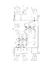
図10は、ION212の機能モジュールのブロック図である。ION212、214への入力はデータ線1002、1004と制御線1006である。ION212内の各モジュールは、制御線1006と接続されている制御モジュール1008を含んでいる。制御モジュール1008は、データ線1002からコマンドを受け入れ、またモジュール制御機能を備える。システム機能モジュール1010は、ここに述べたION機能を実現している。ION212、214は、ファブリック・モジュール1020とキャッシュ・モジュール1014とデータ障害許容力モジュール1016と記憶モジュール1018とを含んでいる。これらのモジュールの各々は、制御モジュールと、データ線1002、1004からのデータを挿入し、検索するための作業負荷インジェクタ(注入器)1020と、データの通過を禁止するデータ・フェンス1022とを含んでいる。
【0184】
PIT読取り要求がION212に送られると、IONキャッシュ・モジュール1014の作業負荷インジェクタに転送される。作業負荷インジェクタは、その要求がキャッシュされていれば、直接そのデータを返すことのできるIONキャッシュ・モジュール1014に要求を挿入し、あるいはそのデータ用のバッファを割り当ててそれをION記憶モジュール1018に渡す。ION記憶システム・モジュール1018は、この要求を一つ(以上)の物理ディスク要求に変換して、その要求を適当なディスク駆動機構224に送る。ディスク読取り動作が完了すると、ディスク制御部はディスク読取りの完了を知らせるために割込みを通知する。ION作業負荷インジェクタは、入出力完了PTパケットを生成する。
【0185】
デビットPIT ID(デビット・フィールド912内に格納されている)は、読取り要求内のSASE PIT(これはアプリケーションがディスクのデータを置きたいと思っている場所である)からのクレジットPIT ID(クレジット・フィールド910内に格納されている)である。クレジットPIT IDは、コンピューティング・ノード200がこの要求を送った同じPIT IDであるか、そのバッファが空いていなければ交替のPIT IDであるかのいずれかである。このクレジットPITは、将来の要求を送るためのコンピューティング・ノード・クレジットを与えるであろう(この現在のPIT要求は、ちょうど完了したところなので、このION212に対するこのコンピューティング・ノード200のための待ち行列の深さを1だけ増加させる)。
【0186】
PITを処理した後でION212がPITクレジットを返さない理由は三つある。第一は、ION212はそのコンピューティング・ノード200からの待ち行列に入れられている未解決の要求の数を減らしたいと思っていることである。第二の理由は、ION212はそのPITクレジットを他のコンピューティング・ノード200に再配分したいと思っていることである。第三の理由は、単一のPITパケットに入れられた多数の要求があるかもしれないと言うことである(本書のスーパーPITパケットの論議を参照のこと)。
【0187】
コマンド・フィールド914は、読取り完了メッセージであって、引き数は、ディスク駆動機構読取り操作からの返却コードである。それからこのPITパケットは、コンピューティング・ノード200に送り返されるためにBYNETインタフェース702への待ち行列に入れられる。それからBYNETハードウエアは、このPITパケットをDMAを介してコンピューティング・ノード200に移動させる。これは、目標PITバッファ(この場合はアプリケーションのピン留めされたバッファ)へのDMAを起動する前にコンピューティング・ノード200BYNETチャネル・プログラムがデビットPIT ID912を抽出して検証することを誘発する。DMAが完了すると、コンピューティング・ノード200BYNETハードウエアは、ディスク読取りが完了したことをアプリケーションに知らせる割込みを誘発する。ION212上でBYNETドライバは、バッファをキャッシュ・システムに返却する。
【0188】
書込み要求のために行われた操作は、読取り操作のために行われた操作と類似している。アプリケーションは、コンピューティング・ノード・ハイレベル・ドライバを呼出し、データと仮想ディスク名とディスク・ブロック番号とデータ長とを含むアドレスを渡す。コンピューティング・ノード・ハイレベル・ドライバは、宛て先ION212上のPIT ID906を選択して、このデータを使ってPIT書込み要求を生成する。SASE PITは、ION212からの書込み操作の返却状態のみを含むであろう。ION212では、PITパケットが到着したとき割込みが通知される。
【0189】
この要求は、PIT読取り動作と同じように処理される。書込み要求は、最終的にデータをディスクに書き込むキャッシュ・ルーチンに渡される。ディスク書込みが完了すると(あるいはデータがION212、214の両者の書込みキャッシュ内に安全に記憶されると)、入出力完了メッセージがコンピューティング・ノード200に送り返される。ION212が書込みキャッシュ動作可能状態で走行しているとき、その要求が送られたそのION212よりもむしろ、ダイポール内のもう一方のION214が、入出力完了メッセージを返す。これは、バーミューダ・トライアングル・プロトコルに関して本書で更に詳しく説明する。
【0190】
古くなったPIT IDと障害回復問題
最初オープン時のPIT IDの交換は、ハードウエア障害またはソフトウエア障害のいずれかによって生成された、古くなったPIT ID906を無効にする機構である。ION212とコンピューティング・ノード200がPIT IDを交換して、突然そのION212がクラッシュした状況を考えてみる。PIT ID906は、メモリ内にピン留めされた目標バッファを表しており、無効にされなければ、再ブートしたばかりのION212かコンピューティング・ノード200かいずれかに関する未解決PIT ID906は、もはや有効でないあるいは古くなったPIT IDのせいで重大なソフトウエア完全性問題を引き起こすであろう。BYNETハードウエアと有向帯域メッセージ・サポートとは、古くなったPIT ID906を無効にするための重要な機構を提供する。
【0191】
最初オープン・プロトコルの終わりで、各側は、PIT IDが配布されるホストのリストをコンピューティング・ノード・ハイレベルSCSIドライバに与えなくてはならない。言い換えればホストは、それがPITパケットを受け入れるであろうホストのリストをコンピューティング・ノード・ハイレベルSCSIドライバに与えている。それからコンピューティング・ノード・ハイレベル・ドライバは、このリストを使って、有向帯域メッセージの送達を制御する表を作成する。この表は、有向帯域メッセージが互いに送られることを可能にするION212対の組合せを指定する。(この表は、一方向PITメッセージ流れを指定することもできる。)
【0192】
このコンピューティング・ノード・ハイレベル・ドライバは、BYNET構成処理の一部として(ドライバに専用のデータとして)ホスト上で内部的にこの表を保持する。ホストは、コンピューティング・ノード・ハイレベル・ドライバへの簡単な通知メッセージによって、何時でもPITプロトコルによってこのリストに追加または削除することができる。ノードが故障、停止、あるいは応答停止のとき、BYNETハードウエアは、これを検出してファブリック上の他のすべてのノードに通知するであろう。
【0193】
各ノード上のBYNETホスト・ドライバは、この通知に応答して、有向帯域ホスト・テーブルからそのホストに関するすべての参照事項を削除する。この動作は、そのホストが他のホストに配布した可能性のあるすべてのPIT ID906を無効にする。これは、前に配布されたPITパケットからノードを保護するために基本的なことである。そのホスト上のコンピューティング・ノード・ハイレベル・ドライバが再構成されるまで、BYNETは、そのホストに送られるすべてのメッセージを放棄するであろう。再構成の後でもローカルPITプロトコルによって知らされるまではBYNETは、いかなる有向帯域メッセージもこの新たに再起動または再構成されたホストに送ることを許さないであろう。これは、PITプロトコルが最初オープン・プロトコルによって適切に初期化されるまでは、いかなる古くなったPITパケットの送付も行われないように保護することになる。
【0194】
あるホストが有向帯域メッセージを無効なホスト(いま無効にされたPIT ID906を使っている)に送ろうとすると、送信側のコンピューティング・ノード・ハイレベル・ドライバは、送信側に対する誤り条件によってそのメッセージを拒否する。この拒否は、最初オープンのハンドシェーキングが二つのノード間で呼び出されることを誘発する。最初オープン・ハンドシェーキングが完了した後、未だ保留になっている(コンピューティング・ノード200の見込みから)ION212に関するいかなる入出力操作も再送しなくてはならないであろう。
【0195】
しかしながらこれがウォーム再起動でなかったとすれば、ION212は長時間ダウンしていたことになりそうであり、したがっていかなる保留中の入出力操作も失敗回復処理の一部として再起動されて、ダイポール内のもう一方のION212に送られたであろう。(更に詳しくは、ION障害回復のセクションを参照のこと)。
【0196】
もしクラッシュしたノードがコンピューティング・ノード200であったならば、最初オープンを既に行ったコンピューティング・ノード200に関するION212における最初オープン要求の予期しない到着は、PIT ID回復操作を誘発するであろう。ION212は、コンピューティング・ノード200にクレジット(信用貸し)されたすべてのPIT ID906を無効にするであろう(あるいは実際には多分、旧いものを再発行するだけであろう)。
【0197】
そのコンピューティング・ノード200に関するいかなる保留入出力操作も完了することが許される(これは、ノードの再起動の時間が極端に速くなければありそうもないケースであるが)。完了メッセージは、それが使っているSASEPITが古くなっているであろうから放棄されなくてはならないであろう(そして入出力要求を発行したアプリケーション・スレッドは、もはや存在しないであろう)。
【0198】
スーパーPIT(SPIT)−小さな入出力性能の改善
PITプロトコルは、通常のSCSIコマンドよりも優れた点を持っている。本発明の核心は、記憶装置ネットワークではなく通信ネットワークであるから、記憶装置モデルが許すものに対する性能改善のためにネットワーク・プロトコルを使うことができる。アップコール処理のオーバーヘッドの処理は、小さな入出力要求が優位を占めている作業負荷に関して性能の壁を表している。小さな入出力の性能を改善するための手法は、幾つかある。
【0199】
一つの手法は、割込み処理符号の経路長を改善することである。第二は、デバイス・ドライバに採用されている手法に類似の手法を使って、多数の割込みの方向指示を割込みハンドラーの単一の呼出しの中に折り込むことである。第三は、個別の入出力操作の回数を減らしてそれらを単一の要求にクラスター化する(あるいはコンボイする)ことである。
【0200】
発信元と宛て先との物理リンク上の異なるMTUサイズのために着信と送出のデータの流れを再パッケージングしなければならないノードは、データを集める傾向がある。この問題は、送信側ネットワークと宛て先側ネットワークとの間の速度の不整合によって(特に宛て先側ネットワークの方が遅い場合)、更に悪くなる。これらのノードは、宛て先側からの流れ制御を絶えず受けている。その結果、トラヒックはルーターからバーストになって流れ出ることになる。これは、データ・コンボイと呼ばれる。
【0201】
本発明は、ION212とコンピューティング・ノード200の両者におけるアップコール発生による割込みの回数を減らすための手法としてデータ・コンボイを利用している。説明のために、ION212からコンピューティング・ノード200へのデータ流れを考える。本発明によって使われる流れ制御に関するデビット/クレジット・モデルでは入出力要求は、コンピューティング・ノード200とION212の両者において待ち行列に入る。待機は、ION212に格納されたPITパケットで始まり、それが枯渇すると待機はコンピューティング・ノード200に戻って続けられる。これは、オーバーフロー状態と呼ばれる。
【0202】
通常、オーバーフローは、ノードがPITバッファ・クレジットよりも多くの要求を持っているときに発生する。入出力が完了する度毎にION212は完了メッセージをコンピューティング・ノード200に送り返す。通常この完了メッセージは、いま解放されたばかりのPITバッファ資源に関するクレジットを含んでいる。これは、デビット/クレジット流れ制御の基礎である。システムが入出力要求で渋滞すると、各入出力完了は直ちに、ION212における新しい入出力要求に置き換えられる。したがって負荷の大きいときには、入出力要求は一度の一つずつION212に流れて、指定されていない期間、ION212内で待機する。これらの要求の各々は、ION212の負荷を増加させるアップコール割込みを発生させる。
【0203】
この二重待ち行列モデルは、多くの利点を持っている。コンピューティング・ノード212に割り当てられたPITバッファの数は、慎重なトレードオフである。要求が完了したとき新しい仕事を素早くディスパッチできるように、ION212にはローカルに待機している十分な仕事負荷が存在がしているべきである。しかしながらION212上に待機している要求によって消費されるメモリ資源は、キャッシュ・システムに割り当てられれば更によく利用できる。ION212上のPIT待ち行列がメモリを節約するために短時間だけ保持されるとき、ION212が遊休状態になると性能は低下して、仕事がコンピューティング・ノード200から送られてくるのを待たなくてはならない。
【0204】
スーパーPITは、アップコール割込みの回数を減らすために高い負荷のデビット/クレジット・システムの流れ制御を利用するように設計されたPITプロトコルの一形態である。スーパーPITは、OLTPの性能を改善し、また比較的小さな入出力の高い割合によって支配される同様な仕事負荷を改善する。一度に一つずつ要求を送る代わりに、スーパーPITパケットは、単一の、大きなスーパーPIT要求ですべて送付される入出力要求の集まりである。各スーパーPITパケットは、通常のPITバッファと同じように搬送される。それから、スーパーPITパケット内に含まれる個別の入出力要求は、抽出されて、ION212資源が利用可能になると、PIT仕事負荷インジェクタによって通常のION212待ち行列機構の中に挿入される。これら個別の入出力要求は、読取り要求か書込み要求かどちらでもよい。
【0205】
PIT仕事負荷インジェクタは、ION212に送られたアプリケーション要求のローカルな代理として(ION212上で)動作する。PIT仕事負荷インジェクタは、後のセクションで論じられるRT−PITプロトコルとFRAG−PITプロトコルとによっても使われる。スーパーPITが個別の要求を使い切ると、資源はコンピューティング・ノードに解放され、それと交換するために別のスーパーPITパケットを送ることができる。1ホスト当たりに許されるスーパーPITパケットの数は、最初オープン折衝で決定されるであろう。ION212上で待機する仕事の量は、別のスーパーPITパケットが送付できるまでそのION212を動作中にしておくのに十分でなければならないことは明らかである。
【0206】
コンピューティング・ノード200がION212内の十分な仕事がPITクレジットを使い切るのを待っていて、ローカルに要求を待ちはじめたと言う状況を考えてみる。スーパーPIT要求内で待機している要求の数は、そのスーパーPITが送られるバッファのサイズによってだけ制限される。スーパーPITパケットは、通常のPITパケットとは異なる動作をする。本発明の制御モデルでは、もしユーザが宛て先に関するクレジットを持っている場合、装置は要求(デビット)だけを送ることができる。装置はION212内の特定のアプリケーション・スレッドを目標にしているわけではないので、その装置によって使われた特定のPITパケットは、特に重要ではない。ION212に対するPITパケットは、単にバッファ利用(および副作用として流れ制御)を規制するだけである。これに対してPIT要求内のSASE PITは異なる。
【0207】
SASE PIT IDは、コンピューティング・ノード212内の個別スレッドのアドレス空間を表す。スーパーPIT内の各要求は、SASE PITを含んでいるが、それらが表す入出力が完了すると、作成された入出力完了メッセージはクレジットPITを含まない。スーパーPITがすべての要求を使い切ったときだけそのアドレス空間にクレジットPITが発行される。
【0208】
コンピューティング・ノード200上でのスーパーPITの生成は、下記に述べるように行われる。単一のION212に対する入出力要求がコンピューティング・ノード200内に二つ以上待機しているときは何時でも、スーパーPITを生成することができる。もしそのコンピューティング・ノード200に関するスーパーPITパケットの限界が既にこのION212上で到達されていた場合、コンピューティング・ノード200は、スーパーPIT IDが返却されるまで要求を待ち行列に入れつづけるであろう。それからこのコンピューティング・ノード200は別のスーパーPITメッセージを発行する。システム・ドライバ内では、一旦待機が始まるとIONごとの待ち行列がスーパーPITパケットを生成するように要求されるであろう。
【0209】
前に論じたように、スーパーPITメッセージは、大量の小さな入出力要求によって占められている仕事負荷の下でION212上の処理負荷を減らすことができる。スーパーPITメッセージは、宛て先ノードの性能を改善し、また平均メッセージ・サイズの増加によって相互接続ファブリック106の利用を改善する。しかしながらスーパーPITメッセージのコンセプトは同様に、小さな入出力仕事負荷によって作り出されるコンピューティング・ノード200上の負荷を減らすためにION212で応用することもできる。ION212上にスーパーPITメッセージを作成することは、コンピューティング・ノード200上にそれらを作成することとは全く異なる問題である。
【0210】
コンピューティング・ノード200上では、入出力要求を作成するアプリケーション・スレッドは、ION212が圧倒されるのを防止するために流れ制御を受けている。ディスク・サブシステムのサービス速度は、ION212のそれ以外のものよりも遙かに遅く、常にION212性能の究極の限界になるであろう。要求は、要求を待ち行列にいれて最後にはその要求に応えるために十分な資源をION212が持つまでは、システムに入らないように阻止される。
【0211】
要点は、資源がION212上で利用可能になるまで要求はコンピューティング・ノード上で待機するであろう(あるいはアプリケーションは阻止されるであろう)と言うことである。資源不足は、コンピューティング・ノード200上では問題にはならない。コンピューティング・ノード200アプリケーションが入出力要求をシステムに出すとき、その要求の一部として、入出力を完了させるために必要とされるコンピューティング・ノード200メモリ資源(アプリケーション・スレッド・バッファ)が含まれている。ION212がコンピューティング・ノード200に送るために必要とするすべての入出力完了メッセージに関して、このノードは既に割り当てられたPIT ID(SASE PIT ID)を持っている。
【0212】
ION212の観点から見れば、入出力完了メッセージは既に割り当てられた目標バッファを持っており、データが準備され次第すぐに満たすことができる。入出力完了メッセージは、一旦送付されれば成功である(ION212は、コンピューティング・ノードでのディスク記憶システムのサービス時間を待つ必要はない)。したがってION212は、コンピューティング・ノードからの流れ制御圧力によって阻止できない。スーパーPITメッセージを作成するためにコンピューティング・ノードは、ION212が持っていないオプションである流れ制御待機を利用した。ION212はBYNETへのアクセス以外に待つべき資源を持たないので、スーパーPITメッセージを作成する機会は、遙かに小さくなる。
【0213】
ION212上にスーパーPITメッセージを作成するために幾つかの手法が採用できる。一つの手法は、スーパーPITパケットを作成する機会を増やすために入出力完了要求を僅かに遅らせることである。もし僅かの遅延の後に同一ノードのための新しい完了メッセージが用意されなければ、そのメッセージは正常なPITメッセージとして送られる。この手法の問題は、スーパーPITを作成すること(コンピューティング・ノード上でのアップコール・オーバーヘッドを減らすこと)を期待して要求を遅らせた時間の量が幾らであっても、それに対応する全体の要求サービス時間の増加があると言うことである。
【0214】
正味の効果は、コンピューティング・ノード200の負荷の減少分であるが、アプリケーションを遅くする可能性もある。適応的な遅延時間が有益であろう(コンピューティング・ノード200に対する平均サービス速度と所定の要求によって累積される総サービス時間とによって)。第二の手法は、第一の僅かな変形である。これは、各コンピューティング・ノード200がそのコンピューティング・ノードにおける小さな入出力の速度が増加するに従って増加する遅延時間を各ION212に与えることを要求するであろう。
【0215】
要点は、必要な場合に特定のION212に関するスーパーPITメッセージを作成するためのウィンドウを大きくすることである。第三の手法は、キャッシュによって直接サービスされて記憶224ディスク操作を待つことに関係しない小さな読取りまたは書込みといった、ある幾つかの型のトラヒックを遅延させることであろう。キャッシュは、あるパーセンテージの要求のためのディスク・トラヒックを回避することによって平均入出力待ち時間を減らすが、待ち時間の分布はキャッシュ・ヒットによって変わる。
【0216】
キャッシュ・ヒット要求のための僅かな待機遅延時間は、ディスク操作を含む遅延時間と比較してサービス時間の主要な増加とはならないであろう。サービス時間の分布に敏感なアプリケーションに関しては(均一な応答時間が性能にとって重要である場合)、ION212上でスーパーPITパケットを作成するための僅かな遅延は、全体的なシステム性能を改善する可能性を持っている。
【0217】
大ブロック・サポートと断片化PITパケット
データベース・アプリケーションに関する性能要件は、データベースの大きさとは無関係であることが多い。データベースのサイズが大きくなるにしたがって、ディスク記憶装置が調べられる速度もまた、アプリケーション性能の劣化を防止するために比例的に増加しなくてはならない。言い換えればサイズの成長する顧客データベースに関しては、応答時間は所定の問合せについて一定に留まらなくてはならない。これらの要件を満たすことの困難さは、ディスク駆動技術の現在の傾向と直接矛盾していることである。
【0218】
ディスク駆動機構は、容量は増加しつつあるが、ランダムな入出力性能は一定のままに留まっている。この傾向を緩和する一つの手法は、ディスク駆動機構の容量の増加につれてディスク入出力操作の平均サイズを大きくすることである。記憶容量の現在の傾向と性能要件とに基づいて、24KBという平均入出力サイズは、極く近い将来に128KBに増えるかも知れない。更に積極的なキャッシング手法と遅延書込み手法も、多くの仕事負荷にとって有益であることが分かるかもしれない。ディスク駆動機構における不均一な技術進歩が、入出力要求サイズの増大の蔭の唯一の推進要因ではない。BLOBS(binary large objects:大きな2進オブジェクト)を有するデータベースがポピュラーになり始めるにつれて、1MB以上に達するサイズのオブジェクトが更に一般的になりつつある。この特定の原因とは無関係に、システムはディスク記憶装置の経済性の追求を続けさせるサイズの大きな入出力オブジェクトをサポートする必要があるであろうということが予想される。
【0219】
PITプロトコルを使用するION212とコンピューティング・ノード200との間の大きなデータ・オブジェクトの伝送に関連して、幾つかの問題がある。ここに述べたように、PITプロトコルの利点は、流れ制御と端点探索の問題に取り組むための宛て先側バッファの事前割当てである。しかしながらアップコール意味論もまた、メッセージを置く十分なバッファ領域の識別(または割当て)を必要とする。PITプロトコルは、受信側で各メッセージが置かれるべき目標PIT ID906を送信側に選択させることによってこの問題に対処している。
【0220】
メッセージ・サイズは、利用可能プールから所定のPIT ID906を選択するための基準になるであろうから、大きな入出力書込みがプロトコルを複雑にすることは明らかである。負荷の大きい間は、送信側は利用可能なPIT ID906クレジットを所有しているが、そのうちのどれも大きな入出力要求に関するバッファ・サイズ要件を満たしていないといった状況の可能性が存在する。PITプロトコルの下では、もし送るべきデータ・サイズの幅広い母集団が存在する場合、送信側はPITバッファの数とサイズの両方を管理するために受信側と一緒に働かなければならない。
【0221】
これは、PITバッファ割当てサイズ問題を作りだす。すなわちPITバッファのプールを作成するときに、所定の仕事負荷の下でのPITバッファのプールに関するバッファ・サイズの適切な配分とはいかなるものであるか?BYNETソフトウエアは、書込みに加えて大きな入出力読取りを複雑にする限界を追加の最大トランスファ・ユニット(MTU)に賦課する。BYNET MTUを超える入出力要求(読取りと書込みの両方)は、送信側でソフトウエア・プロトコル(この場合はPITプロトコル)によって断片化され、宛て先側で再組立てされなくてはならない。これは、メモリ断片化の問題を作りだす。
【0222】
つまり内部的断片化は、割り当てられたバッファ内の領域を浪費することになる。外部的断片化は、どんな要求でも満足させるというには小さすぎる割当て済みのバッファの外側の領域を浪費する。一つの解は、大きなPITバッファの一部だけを使うことであろうが、これはもし大きなPITバッファが使われると、不必要な内部的断片化を引き起こすことになる。大きなPITバッファは、コスト・パフォーマンスを悪くするメモリを浪費する。
【0223】
本発明ではBYNET MTUおよびPITバッファ・サイズ割当て問題は、二つ以上の型のPITメッセージ、すなわちRT−PIT(往復旅行PIT)とFRAG−PIT(断片化PIT)とを追加することによって解決される。RT−PITとFRAG−PITの両者は、PITデータ・プッシュ・モデルの代わりにデータ・プル・モデルを使う。(データを押すためには、送信側がデータを宛て先側に押す。データを引くためには、宛て先側が送信元からデータを引く)。FRAG−PITメッセージは、大きなデータ読取りをサポートするように設計されているが、RT−PITメッセージは大きなデータ書込みをサポートする。FRAG−PITとRT−PITは両者とも、ION PIT仕事負荷インジェクタを使ってデータの流れを管理するのでスーパーPITに似ている。
【0224】
RT−PITメッセージ
コンピューティング・ノード200がION212に対して大きなディスク書込み操作を行いたいと思い、そしてその入出力書込みがBYNET MTUあるいは利用可能なION212PITバッファのどちらよりも大きい場合は、このコンピューティング・ノード200はRT−PIT作成メッセージを作成するであろう。RT−PITメッセージは、ブースト・フェーズとそれに続く往復旅行フェーズという二つの段階で動作する。
【0225】
ブースト・フェーズでは、書き込むべきデータのためのソース・バッファのリストが、コンピューティング・ノード200上の一連のPIT IDに割り当てられる。ソース・バッファの断片化サイズは、BYNET MTUとION最初オープン・プロトコル時に指定されたサイズ制限とによって決定される。PITIDのこのリスト(対応するバッファ・サイズを有する)は、単一のRT−PIT要求メッセージのペイロード内に置かれて、宛て先ION212へのPITクレジットになるであろう。
【0226】
追加のPITバッファは、RT−PITプロトコルによって直接使われるコンピューティング・ノード・プールから割り当てられる。この追加バッファのPIT IDは、PITヘッダのクレジット・フィールド内に入れられる。RT−PIT要求の残余分は、正常なPIT書込みメッセージと同じである。それからコンピューティング・ノード200は、このRT−PIT要求メッセージをION212に送る(ブーストする)。
【0227】
ION212では、PIT仕事負荷インジェクタが二段階でRT−PIT要求メッセージを処理する。各送信側PIT ID906ごとに、仕事負荷インジェクタは、サイズの一致する、IONキャッシュからPITバッファを要求しなくてはならない。(これは、IONバッファ・キャッシュ内の利用可能メモリ領域に依存して、直ちにすべてか、あるいは一度に一つずつか実行することができる)。PITバッファを整合させることによって、ION212は、書込み要求に合った資源を動的に割り当てるであろう。これで入出力は、修正された一連の正常なPIT転送を使って進行することができる。
【0228】
これでRT−PITメッセージの処理は往復旅行フェーズに入るが、ここでは仕事負荷インジェクタが送信側と宛て先側のPIT IDの一つ(以上)の整合している対に関してRT−PIT開始メッセージを作成する。(整合PIT IDの1個あるいは1サブセットを送るオプションは、ION212の自由裁量に任されている)。単一のRT−PIT開始メッセージ内のPIT ID906の数は、ION212内部のデータ転送の粒度(実行単位)を制御する(以下に述べる)。
【0229】
このRT−PIT開始メッセージは、コンピューティング・ノード200に返送されてRT−PITメッセージのブースト・フェーズを終了する。RT−PIT開始メッセージを受信するとコンピューティング・ノード200は、通常のPIT書込みメッセージを使って、一時にPIT対を1対ずつ、ION212にデータを転送しはじめる。コンピューティング・ノード200とION212は両者とも紛失断片を処理するために十分なデータを持っているので、これら断片はコンピューティング・ノード200によって順序よく送る必要はない(整合PIT対が再組立ての順序を指定する)。
【0230】
ION212がPIT書込みメッセージを受信すると、仕事負荷インジェクタは、この書込み要求が大きなRT−PIT入出力操作の一部であることをどちらが認識したのかを知らされる。仕事負荷インジェクタは、PIT書込みを処理するための二つオプションを持っている。すなわち断片をキャッシュ・ルーチンに渡して書き込み操作を開始するか、書込みを開始する前に最後の断片の伝送を待つかのどちらかである。入出力を早く開始することは、キャッシュ・ルーチンがディスク駆動機構へのデータ流れをパイプライン処理することを可能にする(書込みキャッシュ方針による)が、より小さな入出力サイズに起因する性能損失の危険がある。しかしながらすべての断片が到着するまで入出力を保留していることは、キャッシュ・システムに不当な負荷を掛ける可能性がある。
【0231】
断片の全体の大きさと数は初めから分かっているので、現在の動作条件下でこの大きな入出力要求を最適化するために必要とされるすべてのデータは、キャッシュ・システムによって作られる。コンピューティング・ノード200では、多数の断片が単一のRT−PIT開始メッセージ内に含まれる場合には各PIT書込み動作の伝送の成功は、次の断片書込みを開始させる。単一のRT−PIT開始コマンド内の最後の断片が受信されると、要求インジェクタ(注入器)は、通常の書込み要求の処理に類似の処理のためにそのデータをキャッシュ・システムに渡す。データが安全であるときは、入出力完了メッセージはキャッシュ・システムによって作成されて、(RT−PIT開始動作のための)処理のこの段階の完了を知らせるためにコンピューティング・ノード200に返送される。
【0232】
更に多くの断片が残っている場合は、別のRT−PIT開始コマンドが生成されてコンピューティング・ノードに送られ、すべての断片を処理し終わるまで、こうして上述のサイクルを繰り返す。仕事負荷インジェクタとキャッシュが最後の断片の処理を完了すると、RT−PIT要求に関するすべての処理の終了を同期させるために、状態を有する最後の入出力完了メッセージがコンピューティング・ノードに返される。
【0233】
RT−PITメッセージは、BYNETに幾つかの変更を行うことによって最適化できる。ION212がちょうどRT−PIT要求を受信したばかりという状況を考えてみる。ION212上の仕事負荷インジェクタは、大きな入出力要求を多数の小さな通常の書込み要求に変換するためにコンピューティング・ノード上のバッファをION212に整合させている。中間のRT−PIT開始コマンドによって同期化が行われる。しかしながらもしBYNETが受信チャネル・プログラムにデータ・プルの実行を許したとすれば、RT−PIT開始コマンドをコンピューティング・ノードに送るという中間ステップは除くことができるであろう。
【0234】
論議のためにBYNET操作のこのモードをループバンド・メッセージと呼ぶことにする。ループバンド・メッセージは実は、一方が他方のなかに入れ子になっている二つの有向帯域メッセージである。例として、仕事負荷インジェクタは、RT−PIT要求を受け取ると、コンピューティング・ノード上で第二のPIT書込みメッセージを作成するために必要とされるデータを含むRT−PIT開始メッセージを作成することによって各断片を処理するであろう。RT−PIT開始メッセージは、ある断片に関するPIT書込み操作のためのテンプレートをコンピューティング・ノード200に転送する。コンピューティング・ノード200上で実行されるチャネル・プログラム(RT−PIT開始メッセージと一緒に送られる)は、コンピューティング・ノードBYNETドライバ上の送信待ち行列にそのペイロードを入れる。
【0235】
このペイロードは、初期RT−PIT要求を行ったアプリケーション・スレッドからの待機している要求のように見える。このペイロードは、仕事負荷インジェクタによって送られたこの断片のために送信元のPIT IDと宛て先のPIT IDとの対を使ってPIT書込み要求を作成するであろう。PIT書込みは、ION212上にこの断片を置き、それが到着したことを仕事負荷インジェクタに通知するであろう。仕事負荷インジェクタは、すべてが処理し終わるまで各断片についてこのサイクルを続けるであろう。ループバンド・メッセージの性能改善は、各RT−PIT開始メッセージのために必要とされる割込みとコンピューティング・ノード処理とを除去することから得られる。
【0236】
FRAG−PITメッセージは、コンピューティング・ノードからの大きな入出力読取り要求の操作をサポートするように設計されている。アプリケーションが大きな入出力読取り要求を行うと、コンピューティング・ノードは、目標バッファをピン留めして、各断片の目標バッファを表すPIT IDのリストを作成する。各PIT IDは、その断片に関する目標バッファとそれに関連する状態バッファとからなる分散リストを記述している。状態バッファは、データが送られると更新され、各断片が何時処理されたかをコンピューティング・ノードが決めることを可能にしている。各断片のサイズは、RT−PITメッセージと同じアルゴリズムを使って決定される(前述のRT−PITについてのセクションを参照のこと)。これらのフィールドは、FRAG−PITを生成するために組み立てられる。
【0237】
コンピューティング・ノード200は、仕事負荷インジェクタによってFRAG−PITが処理されるION212にそのFRAG−PITを送る。この要求には、ION212上の仮想ディスク名と開始ブロック番号とデータ源のデータ長とが含まれる。仕事負荷インジェクタは、RT−PIT要求と同様の方法でFRAG−PIT要求に作用する。FRAG−PIT要求内の各断片は、キャッシュ・システムの協同の下で別々のPIT読取り要求として処理される。キャッシュ・システムは、各断片を独立に処理するか単一の読取り要求として処理するかを選択することができ、利用可能なときにはディスク・データを仕事負荷インジェクタに送り返す。
【0238】
データ断片がキャッシュによって供給されると(個別にか、単一の入出力操作の一部としてかのどちらかで)、大きな読取り要求のためのデータは、コンピューティング・ノードに流れはじめるであろう。キャッシュがデータを利用可能にした各断片ごとに、仕事負荷インジェクタは、FRAG−PIT部分完了メッセージ内のそのデータ断片をコンピューティング・ノードに送り返す。各FRAG−PIT部分完了メッセージは、それが送付されたときにコンピューティング・ノードで割込みを発生させないということを除いて、正常なPIT読取り要求完了に似たデータを送信する。最後に完了した断片は、FRAG−PIT完全完了メッセージと一緒にコンピューティング・ノードに返される。FRAG−PIT完全完了メッセージは、それがFRAG−PIT読取り要求全体の完了を割込みを介して知らせる(フル・アップコール)と言うことにおいて、部分完了メッセージとは異なっている。
【0239】
他のネットワーク装置上でのPITプロトコルの実現
ネットワークに付加された記憶装置に対する前述の手法の性能の多くは、PITプロトコルをサポートする相互接続ファブリック106の能力に依存している。BYNETの場合には、PITプロトコルに良く整合したローレベル・インタフェースが作成された。ファイバ・チャネルといった他のネットワーク・インタフェースも同様に、PITプロトコルをサポートすることができる。
【0240】
バーミューダ・トライアングル・プロトコル
本発明は、IONクリーク226と書戻しキャッシングとを使うことによってデータと入出力の冗長性を提供する。IONクリーク226は、主ION212と兄弟ION214とからなるION212、214といった(一般には対またはダイポール単位で配置される)複数のIONを含んでいる。
【0241】
兄弟ION214 は、主ION212の修正キャッシュ・ページのコピーのための一時記憶として働くことによって、データおよび入出力の冗長性に備えている。IONクリーク226内の各ION212(1対のIONあるいは1個のダイポールとして示される)は、一つのグループのボリューム・セット用の主ION212と、もう一つのグループのボリューム・セット用の兄弟ION214として機能する。
【0242】
高い可用性と書戻しキャッシングとを備えるために、データは、書込みがアプリケーションに肯定応答される前に少なくとも二つの場所で安全に格納されなければならない。この冗長コピーを与えることに対する障害は、書込みが肯定応答された後ではあるがそのデータが永久記憶装置に記録される前に記憶装置制御部が故障した場合に、データ損失を引き起こす可能性がある。
【0243】
しかしながらION212、214は物理的に別個のコンピュータを持っているので、これらのバックアップ・コピーを保持するためには相互接続ファブリック106上での通信が必要である。最適のシステム性能のためには、なお書戻しキャッシングを利用しながら、BYNET伝送と書込みプロトコルに関連の割込みとの回数を最小にすることが必要である。
【0244】
ダイポール226内のディスク224にデータを書き込むための一つの可能なプロトコルは、コンピューティング・ノード200が主ION212と兄弟ION214とに別々に書込み、両ION212、214からの書込み要求に対する応答が受信されるまで待機し、それから主ION212が兄弟ION214に、もはやそのページのコピーを保存する必要がないことを示すパージ要求を送ることであろう。「送信完了」割込みが送信側で抑制されると仮定すると、送られた各メッセージはコンピューティング・ノード200あるいはION212、214上で割込みを発生させるので、このプロトコルは、少なくとも5回の割込みを必要とする。
【0245】
もう一つの可能なプロトコルは、書込み要求を兄弟ION214に送り、応答を待ち、そして肯定応答をコンピューティング・ノード200に送り返すということを主ION212に指示する。このプロトコルも同様に、少なくとも5回の割込みを必要とする。第1の割込みはコンピューティング・ノード200が書込み要求を主ION212に送信するときに発生する。第2の割込みは、主ION212がデータを兄弟ION214に送信するときに発生する。第3の割込みは、兄弟ION214がそのデータの受信を肯定応答するときに発生する。第4の割込みは、主ION212がコンピューティング・ノード200に応答するときに発生し、そして最後の割込みは、データがディスクに安全に転送されて、主ION214がパージ要求を兄弟ION214に送るときに発生する。
【0246】
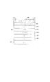
図11は、書込み要求を処理するために必要とされる割込みの回数を最小にする、本発明で使われるプロトコルを示す。このプロトコルは、バーミューダ・トライアングル・プロトコルと呼ばれる。
【0247】
第一に、コンピューティング・ノード200は、書込み要求を主ION212に発行する。第二に、主ION212は、そのデータを兄弟ION214に送る。第三に、兄弟ION214は、肯定応答をコンピューティング・ノード200に送る。最後に、データが安全にディスク上にあるときに、主ION212は、パージ要求を兄弟ION214に送る。
【0248】
上記の4個のステップは、全部で4回の割込みを必要とする。更に割込みを減らすためには、パージ要求(図11のステップ4)を遅らせて、ステップ2で後続の書込みのデータ伝送と結合させ、3回割込みプロトコルを作るようにできる。このプロトコルの更なる利点は、書込み要求が受信されたときに、もし兄弟ION214がダウンしても、主ION212はライト・スルー(書込み遂行)モードでその要求を処理して、一旦そのデータがディスク上に置かれれば、その書込みに対して肯定応答することができると言うことである。コンピューティング・ノード200は、兄弟ION214の状態を知る必要がない。
【0249】
バーミューダ・トライアングル・プロトコルは、データの可用性を維持しながら、従来型プロトコルよりも少ない回数の割込みを使って書戻しキャッシングを可能にしている。これは、主ION212に送られた書込み要求の肯定応答を兄弟ION214が行うからである。現代のパイプライン化されたプロセッサ上では割込み処理は不経済になり得るとすれば、幅広い種々の分散型記憶システム・アーキテクチャで使用できるこのプロトコルは、全体的なシステム・オーバーヘッドを削減して、性能を改善する結果をもたらす。
【0250】
コンピューティング・ノード
概要
コンピューティング・ノード200は、ユーザのアプリケーション204を実行する。従来技術のシステムでは、クラスタあるいはクリーク内のノードに対して等しい記憶装置アクセス可能にするために多数の専用・共用のSCSIバスが使われている。本発明では、記憶装置は一つ以上の通信ファブリック106を介してコンピューティング・ノード200に取り付けられる。このネットワーク付加の記憶装置は、コンピューティング・ノード200に亘って配布されるユーザ・アプリケーション間で処理間通信(IPC)トラヒックを有する通信ファブリック106を共用する。ユーザ・アプリケーション204からの記憶要求は、ファブリック/記憶装置インタフェースによってION212上に配置された記憶装置管理アプリケーションへのIPCメッセージの中に入れられる。記憶装置ノード上のこれらの専用アプリケーションは、IPCメッセージをローカル・キャッシュ操作またはディスク入出力操作に変換して、その結果を必要に応じてコンピューティング・ノード200に送り返す。ユーザ・アプリケーション204にとってネットワーク取付け記憶装置とローカル取付け記憶装置とは区別がつかない。
【0251】
仮想ディスク・ブロックに関する読取り要求と書込み要求は、相互接続ファブリック106を介してION212に到着する。要求は、コンピューティング・ノード200における発信元起動の選択を介して所定のION212に経路指定することができる。すべてのコンピューティング・ノード200は、どのION212がシステム内の各ファブリック仮想ディスクに関する要求を受け入れているかを知っている。ファブリック仮想ディスクは、一意の記憶領域が表される仮想ディスク・モデルを反映するが、その記憶領域は、名前の中の物理ディスクの各物理位置を意味することも符号化することもない。
【0252】
各コンピューティング・ノード200は、ファブリック仮想ディスク名をIONダイポール226に写像するリストを保持している。このリストは、コンピューティング・ノード200とION212との間の協調によって動的に作成される。電源投入と障害回復操作の時にダイポール内のION212は、これらION212の間で仮想(および物理)ディスクを分割して、どの仮想ディスクがどちらの一方のION212によって所有されているかという、仮想ディスクのリストを作成する。ダイポール226内の他方のION214(仮想ディスクも記憶資源も所有しない)は、障害の場合の仮想ディスクへの代替経路を提供する。
【0253】
このリストは、この他のダイポール226とコンピューティング・ノード200とのすべてに対して相互接続ファブリック106の全域で定期的に移出または公示される。コンピューティング・ノード200は、このデータを使って、システム内の各仮想ディスクへの一次経路と二次経路の基本表を作成する。それからコンピューティング・ノード200内の相互接続ファブリック・ドライバは、入出力要求を経路指定するためにダイポール226との協調を行う。ダイポール226は、この「自己発見」手法を使って、ダイポール226がアクティブなシステムに追加されたり、そこから削除されたときに起こる可能性のある仮想ディスクの命名不一致を検出して訂正する。
【0254】
コンピューティング・ノード200上で走行するアプリケーションは、ブロック・インタフェース・モデルを、コンピューティング・ノード200に移出された各ファブリック仮想ディスクに関するローカル・ディスクのように見る。本書で前に述べたように、コンピューティング・ノード200は、ブート時に各ファブリック仮想ディスクへの入口点を生成し、またコンピューティング・ノード200とION212との間に確立された命名プロトコルを使ってこれらの入口点を動的に更新する。
【0255】
サーバ管理
概要
本発明の重要な一面は、その管理であって、これはシステム管理あるいはシステムズ管理と呼ばれる全体的管理のサブセットである。このサブセットは、記憶装置に関するサーバ管理(SMS)と呼ばれる。記憶装置関連のハードウエア・コンポーネントとソフトウエア・コンポーネントとの管理ならびに利用可能な記憶領域内のデータ・エンティティの配置は、この機構によって実現される。管理動作は、管理者によって初期化でき、あるいはシステム内でのある事象の発生時に動的に呼び出される。管理コマンドは、入力されて、殆ど瞬時に肯定応答され得るが、単一の簡単なコマンドの結果は、かなり長時間に亘って多数のシステム・コンポーネントに容易に影響を与える可能性がある。例えば、ボリューム・セットを一方のION212から他方のIONに移動させることは、完了までに何分も、いや何時間も要することがあり、主題のファイル・システムを使いたがっている多数のION212とコンピューティング・ノード200とに影響を与えることになる。サーバ管理はまた、システムのハードウエアとソフトウエアの状態に関する情報メッセージと警告メッセージとを管理者に提供する責任も持っている。
【0256】
管理者は、主として一連の画面表示「ビュー」を通してシステムを感知している。システム全体の幾つかのビューが提示されることもある。主要ビューは、最上位レベルにシステム内のすべてのコンピューティング・ノード200とION212とファブリック106とが表示される、階層的ビューである。ドリルダウン手法によって関心のある項目の更に詳しい表示が得られる。大抵のシステムはサイズが大きくて非常に複雑なので、単一の表示ページ上では表現しきれない。図形的ビューは、物理的(機器構成的)ビューまたは論理ビューのどちらかを表示して表現される。更に詳細なビュー化と管理とのために個別エンティティあるいはエンティティのグループが選択され、要求の結果はユーザ選択のフォーマットで表示できる。
【0257】
表による表現方法も用意されており、個体でもグループでも、このビューで見て管理することができる。この管理の重要な一面は、特定のコンピューティング・ノード212から、特定のデータ片の、そのデータ片を持っている物理記憶ディスク224への経路の表現である。この経路は、その障害許容力を、すなわち、どれだけ多くの個別コンポーネントが障害を起こしたらデータが利用不能になるかを表示する表形式で表現される。
【0258】
ボリューム・セットの作成
ボリューム・セット(VS)の作成は、ホストのコンピューティング・ノード200アプリケーション204によって使われる空き領域を割り当てる。ボリューム・セットは、ION212内に基礎を置いており、名前(ここで述べたVSI602)と、サイズと、RAID(redundant array of inexpensivedisks:低価格ディスクの冗長配列)データ保護レベルとを持っている。システム管理者は、要件に基づいてVSを作成し、位置と冗長性特性とを指定できる。多数のVSがグループ操作で作成できる。
【0259】
図12は、単純化されたVS作成インタフェース・ウィンドウ1100の一実施例のスナップを示す。もしすべてのION212上のディスクのすべてが単一領域として見られれば、システム管理者はこのインタフェースを使って、この単一領域プールから領域を割り当てる、ここに述べる自動機能を使うことによってボリューム・セットを作成することができる。この場合、管理者は、このボリューム・セットに関するサイズとRAIDレベルだけを選択すればよい。これらのパラメータは指定されなければ、省略値が使われる。単純化されたVS作成ユーザ・インタフェースは、VS名を示すVSI名ウィンドウ1104を有するVSI特性ウィンドウ部1102と、VSサイズを示すVSIサイズ・ダウンボックス1106とを含む。VS作成ユーザ・インタフェースはまた、ラジオ・ボタン1110によってシステム管理者がサポートされているRAIDレベルを選択できるVSIRAIDレベル・ウィンドウ部1108も含んでいる。
【0260】
OKボタンは、システム管理者によって選択されたデータを入力し、またVS作成ユーザ・インタフェース・ウィンドウ1100を閉じる。このデータは、ボリューム・セットを作成するために要求としてION212に送られる。一旦VSが作成されると、ION212は、選択された操作の完了を表示することによって応答する。この結果は表示されて、名前と場所と内部識別番号と何かの誤りメッセージとその他ユーザ関連のデータとを示す。取消しボタン1114は、何も変更せずにVS作成ユーザ・インタフェース・ウィンドウ1100を閉じ、またヘルプ・ボタン1116は、必要であればヘルプを提供する別のウィンドウを開く。改良型機能は、改良型ボタン1118を介してアクセスできる。
【0261】
図13は、改良型VS作成インタフェース・ウィンドウ1200の一実施例のスナップを示す。この機能を使ってユーザは、性能を最適化するために所定のION212とディスク上にボリューム・セットを配置することができる。改良型VS作成インタフェース・ウィンドウ1200は、移入VSI特性ダウンボックス1202を含んでおり、ユーザがシステム内のすべての既存のボリューム・セットの名前と特性とを見ることを可能にする。
【0262】
この機能に関して取得されるデータは、システム内のボリューム・セットの名前と特性とに関してすべてのION212に問い合せることによって得られる。改良型VS作成インタフェース・ウィンドウ1200はまた、同じ特性を有する多数のボリューム・セットを管理者が作成することを可能にするグループ操作ウィンドウ部1204と、可変VSIレイアウト・ボタン1205とを含んでいる。この操作を完了する前にシステムは、要求によりこの操作を完了するために十分な仮想ディスク(vdisk)が存在することを保証する。
【0263】
もしVS作成が行われているときに多数の操作が進行中であれば、進行中の操作によってどの操作が排除されたかを示すことと、どの対応策(単純な通知から矯正機能までの)が取られるのかを示すこととのために適当なロックと結果報告とを行わなくてはならない。改良型VS作成インタフェース・ウィンドウ1200はまた、読取りキャッシング・オプション部1208と書込みキャッシング・オプション部1216とを含むキャッシュ・オプション部1206も含んでいる。読取りキャッシング・オプション部1208は、順次またはキャッシュの最適化を指定するためのラジオ・ボタン1210と、キャッシング・オプション(図12では後入れ先だしが示されている)を指定するダウンボックス1212と、先読み量に関するダウンボックス1214とを含む。書込みキャッシング・オプション部1216は、順次またはランダムの最適化を指定するためのラジオ・ボタン1218とキャッシング方法を指定するダウンボックスとを含んでいる。書込みと読取りの両キャッシングに関してキャッシング機能はIONソフトウエアによって決定され、ION212から問合せを受ける。
【0264】
改良型VS作成インタフェース・ウィンドウはまた、所定のION212内に仮想ディスク・エンティティの配置を可能にする位置情報部1222を含む。この位置情報部1222は、IONsとION特性とを指定するION位置ダウンボックス1226を含む。図示の実施例では、ION特性は、ION名と、現在利用されているIONのディスク空間のパーセントと、どのくらい多くのディスク空間がそのION212内に残っているかということとを含む。このリストは、一連のラジオ・ボタン1224によって選択されるように、多数の異なるION特性を減少順または増加順に表示できる。これらの選択の表示は、利用情報と空き領域情報とを取得するためのすべてのION212の整列した問合せを介して達成される。ユーザがそう望むなら、VSを形成する特定の物理ディスクが選択できる。ボタン1228は、このサービスへのアクセスを与える。ボタン1230は、前記の情報を入力し、適当な要求をION212に送信し、図12に関して上述した情報を返す。
【0265】
図14は、詳細なVS作成ユーザ・インタフェース・ウィンドウ1300の一実施例のスナップである。このウィンドウは、利用可能な空き領域と空き領域の最大連続ブロックとをリストアップしている、該当するION212の視覚的表現を示す。物理ディスク1308(同図では001〜040とラベル付けされている)に対するFC−1ループ1304およびFC−2ループ1306接続部も示されている。物理ディスクの各々に関する特性の用法は、凡例1312を含む用法部に表示されている。物理ディスク1308のアイコン表示は、選択処理で有用な情報を示すために凡例1312によって変化する。図示の実施例では、この凡例は、物理ディスクの用法をカラーまたは影付けによって示している。ラジオ・ボタン1314は、特性の用法が空間、性能、最良適合、キャッシング、またはこれらの手段の組合せに関して表示されるかどうかの選択を可能にする。
【0266】
管理者は、ディスクビュー・データ・ウィンドウ1316を選択して、そのディスクの現在の使用を決定する。図示の実施例では、データ・ウィンドウ1316は、VSIおよびそれらに関連のサイズと、利用可能な領域およびION1302とのそれらの関係とを示す。それから管理者は、ディスクの上に適当なビルド(構築)・インジケータ・ボックス1318をドラッギングすることによって、またはビルド・インジケータをそのディスク上に移動させるために、プレックス(plex:網)選択部1320内のプレックス選択ボタンの一つを選択することによって、そのディスクを選択する。特定のRAID実現のために各レベルのすべてについて、一旦これが行われると(この例ではRAID5が描かれており、これは4個のプレックス・ディスクと1個のパリティ・ディスクとを必要とする)、VSは構築される。
【0267】
図15は、可変VSIインタフェース・ウィンドウ1400の実施例を示す。この可変VSIインタフェース・ウィンドウ1400は、ユーザが可変VSIレイアウト・ボタン1205を選択したときに現れ、また改良型VS作成ユーザ・インタフェース・ウィンドウ1200は、作成VSIボタン1406を選択することによって再選択できる。移入VSIボタン1402は、VSの名前と特性とに関してすべてのION212に問い合わせてそれらをVSIリストボックス内に表示する。
【0268】
ユーザは、リストボックス1406内に現れるこれらの特性を選択してRAIDラジオ・ボタン1408の状態を読み取ることによって、これらのVSIの特性を見ることができ、あるいはVSI名前ボックス1410内に名前を入力し、RAIDラジオ・ボタン1408からRAIDレベルを、そしてVSIサイズ・ダウンボックスからサイズを選択し、そして入力ボタン1414を選択することによってVSI名を作成することができる。キャッシュ・オプションと位置情報と位置情報とは、図13に示したこれらのエレメントに関して述べた同じ手法を使って、図示の適当なウィンドウによって選択される。
【0269】
図16は、本発明の一実施例を実行するために使われる操作を描く流れ図である。この処理は、各ION212内の利用可能な記憶領域を決定するためにION212に問合せ1502を行うことによって始まる。所望であればION212は、IONダイポール226として問合せされてもよい。次ぎに、利用可能な記憶領域ブロックのアイデンティティと記憶領域ブロック・サイズとを表す、問合せから検索された情報が、表示される1504。
【0270】
次ぎにボリューム・セット名と、最大記憶領域ブロック・サイズ以下の大きさのボリューム・セット・サイズとが受け入れられる1506。それからこの情報は、利用可能な記憶ブロックの記憶ブロック・サイズが選択されたボリューム・セット・サイズに等しいかどうか決定するために走査される1508。もし利用可能記憶ブロックが、選択されたボリューム・セット・サイズに等しいサイズを持っていれば、ブロック1510は、選択されたボリューム・セット・サイズに等しいサイズを有する記憶領域ブロックが選択されたブロック1512に論理を経路指定する。もしそうでなければ、選択されたボリューム・セット・サイズより大きなサイズの利用可能領域ブロックに関する性能データが取得され1514、そしてこのデータが使われて、そのボリューム・セットに関する記憶領域ブロックが選択される1516。
【0271】
図17は、本発明の一実施例において、利用可能な記憶装置について入出力ノードに問い合わせするために実行される操作を描く流れ図である。まず最初に、システム管理者から入出力ノード212にメッセージが送られる1602。随意に、このメッセージは、システム管理者がこのメッセージによって要求された情報を見る権利を持っていることを入出力ノードが認めるようにデジタル署名を含んでいる。次ぎに入出力ノード212は、その署名を認証する1604。要求者(ここではシステム管理者)がそのデータを受け取る資格を持っているということをこの署名が示すと、入出力ノード内の利用可能記憶領域ブロックを記述している情報が受信される1606。
【0272】
ボリューム・セット所有権の折衝
入出力経路の障害は、主ION212か兄弟ION214かのいずれかがVSI602にアクセスできなくなるという結果を招き得る。したがってION212が所有するVSIのワーキング・セットがこのような入出力経路障害のために変更されるのを可能にすることが有利である。各ION212、214は、VSI602の一次セットとVSI602の二次セットとを持っており、ION212はVSI602の一次セットに直接の責任を持ち、ノードまたは経路の障害の場合にVSI602の二次セットに責任を持つ。これを達成するためにIONの二次セット内にあるアクセス不能のVSIは、兄弟ION214上で「書込み遂行」とマークされるが一方、IONの一次セット内にあるアクセス不能のVSIは、関連記憶装置をアクセスに利用可能にするために兄弟ION214に移される。
【0273】
資源を移動させる一つの方法は、全体移動を使うことである。この場合、入出力経路障害は、ION212障害として取り扱われ、そしてVSIの一次セット全体が兄弟ION214に移される。これは、単純な解を提示する一方、発生したのは一つの入出力経路だけであるのに、停止したIONの処理能力と入出力能力を本質的に失うという欠点も持っている。更に悪いことに、二重入出力経路障害、各IONの一次入出力経路の障害は、ダイポール内のすべてのVSI602がアクセス不能という結果になる可能性がある。
【0274】
この問題を防止するために、本発明は、もし主ION212がVSI602にアクセスできない場合、個々のVSI602が兄弟ION214に移動することを許す、VSIの部分移動を使う。したがってVSI602は、ダイポール226内のION212かION214のどちらかがアクセス可能である限り、アクセス可能のままでいる。
【0275】
VSIの部分移動をサポートするためにダイポール226内のIONsは、それが移出できるVSIのワーキング・セット(IONが管理を要求するもの)を調整する。この調整はまた、多忙なVSIを負荷の少ないIONに移動させることによってIONの動的な負荷の最適配分を可能にする。
【0276】
各ION212は、移出に先立ってVSI602のワーキング・セットの独占的所有権に関してその兄弟ION214と折衝を行い、その折衝の結果は、ダイポール226内のどちらのIONが問題のVSI602に対する入出力操作の実行を許されるのかを確定する。
【0277】
もし兄弟ION214が折衝に関して利用できない場合(兄弟ION214の障害があった場合がそうであろう)には、すべてのVSI602の全体移動あるいは全体切替えが行われる。動的な入出力経路障害を処理するために、VSI602所有権折衝は、一日の初めを含めて、そのVSI602構成が変わったときは何時でも、ION212、214によって開始される。
【0278】
VSI602所有権折衝は、主(起動)ION212から兄弟ION214への下記の情報を含むメッセージによって開始される。
【0279】
アクセス可能一次VSI −PRIM
アクセス可能二次VSI −SEC
現在ワーキング・セット −WSET
所望ワーキング・セット −DWSET−PRIMとSECのサブセット
応答側ION(ここでは兄弟ION214)は、起動側の折衝要求とその現在構成とに基づくような情報で応答する。このメッセージ交換に基づき、また下記のサブセクションに示される計算を適用して、独占的所有権は決定できるが、これは、VSI602の可用性を最大にし、またWRITE−THRUとマークされる必要のある単一のIONによってアクセス可能なすべてのVSIを識別するものである。
【0280】
経路障害のないVSI所有権折衝
VSI所有権折衝要求は一般に、一日の初めに一度、開始される。PRIMとSECは、問題のIONによって物理的にアクセス可能なVSI602のセットを含む。WSETは、VSI602のワーキング・セットが確立されていないのでNULL(空)にセットされる。DWSETは、一般にIONの一次セット内で指定されているものと同じVSI602であって、ION212が所有したいと思っているVSI602のリストを含んでいる。もし入出力経路誤りが存在しなければ、PRIMセットとSECセットは、同じである。この場合、応答側のDWSETは、要求側のION二次セットを含む。
【0281】
経路障害のある折衝
ダイポール226に入出力経路障害がある場合は、単一のION212によってアクセス可能なVSIは、識別されて部分移動されるか、WRTE−THRUとマークされることが必要である。
【0282】
図18は、VSI602所有権折衝で実行される操作の流れ図を示す。ブロック1802に示すように経路障害が発生するか、あるいはブロック1804に示すようにノード資源に関する要求が受信されると、起動側ION212から応答側ION214へメッセージが送られる。所有権折衝はまた、ノードがVSI602構成変更を経験したかどうかを調べることによって開始することもできる。このような変更が経路障害を知らせることもあり、他の変更が所有権折衝を開始すべきであるということを示唆する場合もある。
【0283】
ブロック1806に示すように、このメッセージは、PRIMiで示される、起動側ION212にアクセス可能な一次VSI602と、SECiで示される二次VSI602(これも起動側ION212によってアクセス可能)と、WSETiで示される、ION212に関するVSI602の現在ワーキング・セットと、DWSETiで示される、ION212に関するVSI602の所望ワーキング・セットとを含んでいる。下記のように、応答側ION214は、起動側ION212の折衝要求とその現在構成とに基づくような情報で応答する。このメッセージに基づいて、可用性を最大にするVSIの独占的所有権が決定できる。単一のIONまたは二つ以上のIONからアクセス可能なVSIも識別できる。
【0284】
図18に戻って、応答側ION214は、起動側ION212からメッセージを受け取り、そしてもしそのワーキング・セット内にVSIが存在しない(ブロック1808に示すようにこのセットが空である−−これは一般に一日の初めのケースである)場合、DWSETrで示される、応答側ION214に関する所望ワーキング・セットは、PRIMrで示される、応答側ION214に利用可能な一次VSIにセットされる1810。もしWSETrが空でなければ、DWSETrは、WSETrに等しくセットされる1812。
【0285】
次ぎに、応答側ION214は、所望ワーキング・セットDWSETr内の変更を計算する。これは、次のように行われる。最初に、もし図中Fで示される特定のVSI602が問合せ側ION212一次セットPRIMi内とWSETr内とに存在すれば、VSIFはDWSETrから除去される。これは、ブロック1814、1816、1818に示してある。これは、部分移動されたVSI602が起動側ノード212によって再要求されることを可能にする。
【0286】
もしVSIFが問合せ側ノード212に関する一次セット(PRIMiで示す)内に存在しなくて、SECrで示される要求側ノードに関する二次セット内に存在すれば、VSIFはセットDWSETrに追加される。これは、ブロック1814、1820、1824に示す。これは、起動側ノード212にアクセス不能なVSI602の部分移動を可能にし、また起動側ION212に応答側ION214の一次セット内のVSIを要求させることによって動的な負荷の最適配分を可能にする。もちろん、もしVSIFがPRIMi内にもSECr内にも存在しなければ、そのVSIは、どちらのノードからもアクセス不能であり、これはブロック1822によって示されている。この処理は、ブロック1825で示すように、すべてのVSIについて繰り返され、また応答側のノードWSETrに関するワーキング・セットは、ブロック1828で示すように応答側ノードの所望ワーキング・セットDWSETrに等しくセットされる。
【0287】
ブロック1826に示すように、VSI602FがDWSETr内に存在してPRIMiにもSECiにも存在しない場合は、そのVSIは応答側ION214にとって利用可能であるが、問合せ側ION212にとっては利用可能でない。したがってそれは、ブロック1828に示すように書込み遂行(write through)とマークされる。それからWSETrは、ブロック1820に示すようにDWSETrにセットされ、そして応答側ION214に関するWSETrは、ファブリック106に亘って移出される1832。起動側ION212は、VSI所有権折衝応答から自分のワーキング・セットを確立する。DWSETrは、一般に折衝可能ではない。
【0288】
図19は、問合せ側ION212におけるVSI所有権折衝処理を示す流れ図である。先ず、問合せ側ノードに関するワーキング・セットWSETiは、所望ワーキング・セットDWSETiにセットされる。これは、ブロック1902に示す。次ぎに応答側ION214は、問合せ側ION212にメッセージを送る。ブロック1904に示すように、このメッセージは、PRIMrで示される、応答側ION212にアクセス可能な一次VSI602と、SECrで示される二次VSI602(これも応答側ION214によってアクセス可能)と、WSETrで示される、ION214に関するVSI602の現在ワーキング・セットと、DWSETrで示される、ION214に関するVSI602の所望ワーキング・セットとを含んでいる。
【0289】
それから、もしVSIFがDWSETrとDWSETi内に存在しなければ、VSIFはWSETiから除去される。これは、ブロック1906、1908、1910に示す。この場合、応答側ノード214は、VSI602の所有権に関する起動側ION212の要求を拒否したことになる。もしVSIFがPRIMiまたはSECi内には存在するがDWSETiにもDWSETrにも存在しない場合、ブロック1912と1914に示すようにVSIFは、WSETiに追加される。
【0290】
これは、現在所有していないVSI602の所有権を問合せ側ION212が引き取ることを可能にする。この処理は、ブロック1916に示すようにすべてのVSIについて完了される。起動側ION212のワーキング・セットが決定された後、書込み遂行されたVSIをマークする必要があり、こうしてそのVSI602に関するバーミューダ・トライアングル・プロトコルを動作禁止にする。これは、ブロック1918、1920、1927に示す。この時点で起動側ION212はファブリック106全体に亘って自分のワーキング・セットWSETiを移出することができる。
【0291】
最後に、ランダムにアクセス可能あるいは不可能であるVSIは、PRIMrセットとSECiセット両者の中に存在するVSIとして定義できる。ブロック1924、1926、1928がこの決定を示している。この処理は、ブロック1930に示すようにすべてのVSIについて完了される。
【0292】
例
図20は、図示のように表されるVSIs1〜6を共用するIONs212、214間でのVSI所有権折衝交換を示す。ION212は、1〜3の一次セットと4〜6の二次セットで構成されている。ION2は、4〜6の一次セットと1〜3の二次セットで構成されている。
【0293】
ION212は、現在オンラインになっており、そのワーキング・セットはVSIs1、2、3である。ION214は、ちょうどオンラインになろうとしているところであって、それが移出できるVSI602の自分のワーキング・セットを決定したいと思っているので、VSI所有権折衝要求を開始する。ION214は、VSI6とVSI1への入出力経路に障害を持っている。
【0294】
ION214は、下記の情報を含む折衝要求をION212に送る。
【0295】
PRIMi:	4,5
SECi:	2,3
WSETi:	
DWSETi:	4,5
ION212は、その折衝要求を受け取ると、新しいワーキング・セットを計算する。VSI6はDWSETiにはなくてSECiに存在するので、それはDWSETiに加えられる。ION212は、VSI6の部分移動を可能にするために下記の折衝応答を送り返す。
【0296】
PRIMr:	4,5,6
WSETr:	1,2,3
DWSETr: 1,2,3,6
ION212も、自分のDWSETr内のVSI1とVSI6がION214によってアクセスできない(PRIMiにもSECiにもない)と判断したので、それらにWRITE−THRUとマークする一方、両IONsによってアクセス可能なVSIs2、3に関するバーミューダ・トライアングル・プロトコルを動作可能にする。そのワーキング・セットが変化したので、ION212はVSIの新しいワーキング・セットを移出するために再びオンライン状態に入るように求められる。
【0297】
ION214は、その応答を受信すると、自分のDWSETとその兄弟のDWSETとの間に不一致がなく、そしてどちらのDWSETにもアクセス可能なVSIが既に存在しないという理由で、所望ワーキング・セットを自分のワーキング・セットとして使えると判断する。したがってION214は、VSIのそのワーキング・セットを移出するためにオンラインになる。
【0298】
もし入出力経路障害が修復されてVSI6がアクセス可能になれば、ION214は、その所望のワーキング・セットにVSI6を含めることによってVSI6の所有権を再要求するために、別のVSI所有権折衝交換を再開することができる。これは、スイッチバックを実行するために要求される同じ処理である。
【0299】
PRIMi: 4,5,6
SECi: 2,3
WSETi: 4,5
DWSETi: 4,5,6
ION212は、ION214がVSI6の所有権を再要求したがっていると判断すると自分のワーキング・セットからVSI6を除去するように処置をとる。ION212は、折衝応答を送る前に新しいワーキング・セットを移出してVSI6を手放すために、オンライン状態に再び入らなくてはならない。
【0300】
PRIMr:	1,2,3
SECr :	4,5,6
WSETr:	1,2,3,6
DWSETr:	1,2,3
切替え
一つのダイポール226構成内のIONs212、214は、ION212障害の場合にファブリック取付け記憶装置の障害許容力を備えるために物理記憶装置の同一セットに接続される。ION212の障害時には、そのダイポール対の中の残りのION214がVSIの二次セット(あるいはその障害の起きている兄弟IONの一次セット)の所有権を引き受ける切替えが発生する。このION障害の状況では、障害IONのVSIのセット全体が残りのIONに全体移動させられる。兄弟ION214はバーミューダ・トライアングル・アルゴリズムによってファブリック・ベースのインテント・ロギングを行うために利用できないので、単独のIONによって移出されたすべてのVSIは、WRITE−THRUとマークされる。
【0301】
【発明の効果】
要約すれば、分散型処理システムにおいてボリューム・セットを構成する方法と装置について説明されている。この処理システムは、各々が記憶領域を有する複数の入出力(I/O)ノードに通信可能に連結された複数のコンピューティング・ノードを含んでいる。この方法は、システム内の各入出力ノードにおける利用可能な記憶領域を決定するために入出力ノードに問い合わせるステップと、その利用可能な記憶領域を表す情報をユーザに表示するステップと、ボリューム・セット名と最大記憶領域ブロック・サイズより小さな、選択されたボリューム・セット・サイズとを受け入れるステップとを含む。次ぎに本システムは、選択されたボリューム・セット・サイズと実質的に同じサイズの記憶ブロックが存在するかどうかを決定するためにこの情報を走査する。もしこのような記憶ブロックが存在すれば、ボリューム・セットが作成される。もしこのような記憶ブロックが存在しなければ、利用可能な記憶ブロックに関する性能データが取得されて、これがボリューム・セットに関してある選択された記憶ブロックを推奨するために使われる。一実施例では、記憶ブロックは、実用的に限定される小さな記憶領域が最小になるように選択される。そうすればユーザは、推奨された記憶ブロックの一つ、あるいは所望なら別の記憶ブロックを選択することができる。
【0302】
本発明の好適な実施例の前述の説明は、例示と説明のために、提示されている。本発明は、開示された通りの形式だけに限定することも、それですべて網羅することも意図していない。上述の教えるところに照らせば、多くの修正、変形が可能である。本発明の範囲は、この詳細な説明によって限定されるのではなく、ここに添付の特許請求範囲によって限定されることが意図されている。
【図面の簡単な説明】
【図1】 基本的構成エレメントを示す本発明の一実施例の最上位レベルのブロック図である。
【図2】 本発明の一実施例のシステム・ブロック図である。
【図3】 IONの構造とシステム相互接続部とを示すブロック図である。
【図4】 JBOD筐体内のエレメントのブロック図である。
【図5】 ION物理ディスク・ドライバの機能ブロック図である。
【図6】 ファブリックの一意的IDの構造を示す図である。
【図7】 ION筐体管理モジュールと物理ディスク・ドライバとの間の関係を示す機能ブロック図である。
【図8】 BYNETホスト側インタフェースの図である。
【図9】 PITヘッダの図である。
【図10】 ION212機能モジュールのブロック図である。
【図11】 IONダイポール・プロトコルを示す図である。
【図12】 VS作成ユーザ・インタフェースの一実施例を示す図である。
【図13】 改良型VS作成ユーザ・インタフェースの一実施例を示す図である。
【図14】 詳細VS作成ユーザ・インタフェースの一実施例を示す図である。
【図15】 可変VSユーザ・インタフェースの一実施例を示す図である。
【図16】 本発明の一実施例を実行するために使われる操作を描写する流れ図である。
【図17】 本発明の一実施例において利用可能な記憶装置に関して入出力ノードに問い合わせるために実行される操作を描写する流れ図である。
【図18】 VSI所有権折衝において問合せ側入出力ノードで実行される操作を描写する流れ図である。
【図19】 応答側入出力ノードで実行される操作を描写する流れ図である。
【図20】 VSI所有権折衝交換を示す図である。[0001]
[Industrial application fields]
The present invention relates generally to computing systems, and more particularly to a method for providing a single operational view of virtual memory allocation independent of processor or memory cabinet boundaries.
[0002]
[Prior art]
Technological development often comes from the result of a series of technological developments that are seemingly unrelated. These unrelated developments may be important individually, but when they are combined, they can form the basis for significant technological development. Historically, technological growth between components in large and complex computer systems has been uneven, including (1) rapid progress in CPU performance compared to disk I / O performance, ( 2) Development of internal CPU architecture, (3) Interconnect fabric.
[0003]
Over the past decade, disk I / O performance as a whole has grown at a much slower rate overall than node performance. While CPU performance has increased from 40% to 100% annually, disk seek time has improved only 7% annually. If this trend continues as expected, the number of disk drives that a typical server node can drive becomes the dominant component in terms of quantity and price in the largest systems. The point will be reached. This phenomenon has already been revealed in existing large-scale system facilities.
[0004]
Uneven performance expansion is also occurring inside the CPU. In order to improve CPU performance, CPU vendors are adopting a combination of increased clock speed and architectural changes. Many of these architectural changes have been found to be technologies influenced by the parallel processing group. These changes create unbalanced performance and result in less than expected performance improvements. As a simple example, the speed at which the CPU can issue an interrupt is not increased at the same speed as the basic instruction. Thus, system functions (such as I / O) that depend on interrupt performance have not expanded with computing power.
[0005]
Interconnect fabrics also exhibit non-uniform technology growth characteristics. For several years, they have stagnated around a performance level of 10-20 MB / sec. In the past years, a great leap in bandwidth has occurred to the level of 100 MB / sec (or higher). This significant performance improvement has made it possible to economically deploy a system that performs massive parallel processing.
[0006]
This non-uniform performance has a negative effect on application architecture and system configuration choices. For example, with respect to application performance, attempts to increase workload using performance improvements in certain parts of the system, such as improved CPU performance, are often hampered by the lack of equivalent performance improvements in the disk subsystem. Even though the CPU can double the generation of transactions per second, the disk subsystem can only handle a fraction of the increase. The CPU is constantly waiting for the storage system. The overall impact of non-uniform hardware performance growth is that application performance is experiencing an increasing dependence on the characteristics of a given workload.
[0007]
Uneven growth in platform hardware technology also causes other significant problems, such as a reduction in the number of options available to configure a multi-node system. A good example is that the TERADATA 4-node clique software architecture is affected by changes in storage interconnect technology. The TERADATA clique model assumes uniform storage connections between nodes within a single clique. Each disk drive mechanism is accessible from all nodes. When a node here fails, the storage device dedicated to that node can be divided among the remaining nodes. Non-uniform growth in storage technology and node technology will limit the number of disks that can be connected per node in a shared storage environment. This constraint is created by the number of drive mechanisms that can be connected to the I / O channel and the physical number of buses that can be connected in a 4-node shared I / O topology. As node performance continues to improve, we must increase the number of disk spindles connected per node to realize the performance benefits.
[0008]
[Problems to be solved by the invention]
Cluster-type massively parallel processing (MMP) design is an example of multi-node system design that seeks to solve the aforementioned problems. Although the cluster type is limited in scalability, the MMP system requires additional software to present a sufficiently simple application model (in a commercial MMP system, this software is typically DBMS ( Database management system)). MMP also requires some form of internal clustering (clique) with very high availability. Both solutions still create challenges for managing a potentially large number of disk drives, and these disk drives, which are electromechanical devices, have a fairly predictable failure rate. The problem of node interconnection is further exacerbated in MMP systems because the number of nodes is usually much larger. Both of these approaches are again stimulated by the large number of drive mechanisms needed to store and print very large databases, creating a challenge to disk connectivity.
[0009]
The above problem is ameliorated in an architecture where the storage entity and the computing entity that computes over the high performance connectivity fabric function as architectural peer entities. This architecture can increase the flexibility in managing storage and computing resources. However, this flexibility presents some unique system management issues. One such problem is creating volume sets within the large number of processors and disk drives of a massively parallel system, each of which can reside in different cabinets or different physical areas. An object of the present invention is to provide a system management tool that automatically finds all free space on a fabric mounted storage system and presents this data to the administrator so that a volume set can be created. .
[0010]
[Means for Solving the Problems]
The present invention Communicatively connected to multiple input / output nodes each having a storage area Multiple compute nodes A volume set in a distributed multiprocessing system consisting of A method, The method is performed by a device constituting a volume set, For each input / output node Can Available storage block To determine the input / output node Inquiry Ru Steps, each I / O node Kick Available Above Information representing storage area block Because Storage area block identification information and storage area block size When including Above information To the user Steps to display and the volume set name and the selected volume set size not larger than the maximum storage block size From user Accepting; scanning the information to determine if the storage area block size of an available storage area block is substantially equal to the selected volume set size; and Storage block has a size equal to the selected volume set size In case, Selecting an available storage block for the volume set; and if there is no available storage block with a size equal to the selected volume set size, Having a size larger than the volume set size About the available storage block Performance Get the data, Based on the performance data Selecting an available storage block for the volume set. Memory system configuration Provide a method.
[0011]
The present invention also provides Communicatively connected to multiple input / output nodes each having a storage area Multiple compute nodes For configuring a volume set in a distributed multiprocessing system comprising And each I / O node Can Available storage block To determine the input / output node Inquiry Ru Means, each I / O node Said Represents an available storage block Information, Storage area block identification information and storage area block size When including Above information To the user The means to display and the volume set name and the selected volume set size not larger than the maximum storage block size From user Means for accepting and the storage area block size of available storage area blocks is the selected volume set size Or Means for scanning the information to determine whether the available storage block has a size equal to the selected volume set size In case, Means for selecting an available storage block for the volume set, and there is no available storage block with a size equal to the selected volume set size; Having a size larger than the selected volume set size Obtain performance data for the available storage block And based on the performance data Means for selecting an available storage block for the volume set; Consist of It is characterized by apparatus I will provide a.
[0013]
DESCRIPTION OF EXEMPLARY EMBODIMENTS Hereinafter, preferred embodiments of the invention will be described with reference to the accompanying drawings.
[0014]
DETAILED DESCRIPTION OF THE INVENTION
Overview
FIG. 1 is an overview of the peer architecture of the present invention. The architecture includes one or
[0015]
In the architecture shown in FIG. 1, the storage device is no longer tied to a single set of nodes as in the current node-centric architecture, and any node can communicate with all storage devices. This is in contrast to today's multi-node systems, where physical system topologies limit communication between storage devices and nodes and often require different topologies to accommodate different workloads. is there. The architecture shown in FIG. 1 provides a single physical architecture that supports a broad spectrum of system topologies, allowing application software communication patterns to determine the system topology at any point in time. Addresses non-uniform progress. The separation provided by the
[0016]
FIG. 2 shows a more detailed description of the peer architecture of the present invention. The
[0017]
[0018]
FIG. 2 illustrates a medium scale system with a typical 2: 1
[0019]
The present invention also includes management component or
[0020]
The connection between the
[0021]
ION (storage node)
Internal architecture
Hardware architecture
FIG. 3 is a diagram showing further details regarding the configuration of the
[0022]
JBOD FIG. 4 is a diagram showing further details regarding the
[0023]
[Table 1]
[0024]
I / O interface driver architecture
FIG. 5 is a diagram illustrating the ION 212 I / O architecture, including the ION
[0025]
The
[0026]
The FCI low-
[0027]
High level driver
A high level driver (HLD) 502 is the entry point for all requests to the
[0028]
Common (not device specific) part
The common part of the
Cs-init: Initialize the driver structure and allocate resources.
Cs-open: enables the device.
Cs-close: Completes input / output and deletes the device from the service.
Cs-strategy: block device read / write input (Buf-t interface).
Cs-intr: Serves hardware interrupts.
[0029]
These routines perform the same function for all device types. Most of these routines call device specific routines that handle any device specific requirements with a switch table indexed by device type (disk, tape, worm, CD ROM, etc.).
[0030]
This cs-open function ensures that the device exists and is ready for input / output operations to be performed there. Unlike the current system architecture, the
[0031]
During the initial open period, the SCSI device is bound to the command page by issuing a SCSI inquiry command to the target device. If the device responds positively, its response data (including information such as vendor ID, product ID, firmware revision level) is compared to a known device table in
[0032]
The driver
[0033]
All the FCI low-
[0034]
Equipment specific part
The interface between the
[0035]
Handling high-level driver errors / failures
Error handling
Retry
The most common recovery method for
[0036]
When a request is first issued, its retry count is set to zero. Each time a request fails and the recovery procedure is retried, the number of retries is increased. If the number of retries is greater than the maximum number of retries specified on the command page, the I / O operation fails and a message is returned to the requester. Otherwise it is reissued. The only exception to this rule is for unit attention, which is generally an event notification rather than an error. If a unit attention is received for a command and its maximum retry count is set to zero or one, the high-
[0037]
A delayed retry is treated the same as the retry procedure described above, except that the retry is not relocated to the queue for a predetermined time.
[0038]
Failed Scsi-ops
The Scsi-op issued to the FCI
[0039]
[Table 2]
Low-level driver error conditions
A resource shortage error occurs when the desired resource is not available at the time of the request. In general, these resources are system memory and driver configuration memory.
[0040]
The system memory shortage process is performed by semaphore blocking (signal blocking). A thread (a collection of processes) that blocks memory resources will prevent new I / Os from being issued. This thread will remain blocked until I / O completion frees memory.
[0041]
Driver configuration resources are associated with Scsi-op and input / output vector (IOV) list pools. The IOV list is a list of memory start values and length values exchanged with the disk. These memory pools are initialized at the beginning of the day by using adjustable parameters to specify the size of the pool. If the Scsi-op or IOV pool is empty, new I / O will enter and result in these pools becoming larger. One page (4096 bytes) of memory is allocated at a time to enlarge any of the pools. The page is not released until all Scsi-ops or IOVs are released from the new page. If the
[0042]
All resource shortage processes are logged through events.
[0043]
Processing at the beginning of the day
At the beginning of the day, the
[0044]
Failure handling
Two halves of the ION212 dipole are added to the common set of disk units. Both
[0045]
Command page
The
[0046]
The command page function is called from the device
[0047]
Each command page function builds a SCSI command and allocates memory for direct memory access (DMA) data transfer, if necessary. Then, this function returns control to the driver
[0048]
By massaging the returned data / information, the COI can convert non-standard SCSI data / information to standard SCSI data / information. For example, if the device query data contains a merchant ID starting with byte 12 instead of
[0049]
JBOD and SCSI configuration module
An important function of the RAID control unit is to secure data so as not to be lost. In order to perform this function, the RAID software must physically know where the disk unit resides and how its wiring connects it. Therefore, an important requirement for realizing the RAID controller technology is the ability to control the configuration of the storage device. The JBOD portion of the JBOD and
[0050]
[Table 3]
[0051]
Fiber Channel Interface (FCI) low-level driver
The FCI
• xxhw-init Initializes the hardware.
Xxhw-open Determines the current state of the host adapter.
Xxhw-config Sets host adapter configuration information (such as SCSI ID).
Xxhw-start Invoke a SCSI operation if possible.
Xxhw-intr Handles all SCSI interrupts.
[0052]
A low-level driver is a pure SCSI driver that does not know or care about device specifications, but instead is simply a conduit for SCSI commands from a higher level. Residing in this layer are interrupt service routines, hardware initialization routines, mapping and address translation routines, and error recovery routines. Furthermore, multiple types of low level drivers can coexist in the same system. This division between the hardware control layer and the rest of the driver allows the same high level driver to run on different machines.
[0053]
The basic functions of the FCI module are: (1) interface with a SCSI high level driver (SHLD) to convert SCSI Ops to FCI work object configuration (input / output block (IOB)); and (2) different HIM 508s. Providing a common interface to facilitate support of new Fiber Channel adapters through (3) any FC-4 protocol layer (Fibre Channel Protocol (FCP) in the illustrated embodiment) Providing a common FC-3 service, and (4) a timer that protects asynchronous commands (eg, FCP commands, FC-3 commands, LIP commands) sent to the HIM when the
[0054]
A list of important data structures for the FCI
[0055]
[Table 4]
FC basic data structure
Error handling
Errors handled by the FCI low-
[0057]
Multi-stage error handling
The FCI
[0058]
Failed IOB
All input / output requests are sent to the
[0059]
[Table 5]
HIM error condition
Lack of resources
The FCI
[0061]
If a request for an IOB or vector table is made and there are not enough resources to satisfy the request, the I / O is returned to the queue and a timer is set to restart the I / O. The The occurrence of resource shortage is recorded in the log.
[0062]
First day processing
At the beginning of the day,
[0063]
First, the HIM-FindController () function is called for a specific PCI bus and device. This calls a version of FindController (). The JBOD and
[0064]
Failure handling
Two halves of the ION212 dipole are attached to a common set of disk drives. Both
[0065]
Hardware interface module (HIM)
A hardware interface module (HIM) 508 is designed to interface to ADAPTEC's
[0066]
The basic functions of the HIM508 are as follows: (1) Hardware-specific functions that perform Find (find), Configure (initialize), Initialize (initialize), and Send I / O (send I / O) to the adapter. Defining a low-level application program interface (API); and (2) a TCB request (e.g. FC primitive TCB, FC Extended Link Service (ELS)) that allows the SlimHIM / hardware to understand the input / output block (IOB). Interface to FCI low-
[0067]
[Table 6]
Basic HIM structure
First day processing
[0069]
The second entry point is HIM-GetConfiguration, which is called by FCIhw-init () when an adapter is present and puts resource requirements into a given HCB. For the ADAPTEC adapter these resources include IRQ, scratch and TCB memory. This information is determined by making a call to the
[0070]
The third entry point is HIM-Initialize, which is called by FCIhw-init () after resources are allocated and initialized, initializes the TCB memory pool, and calls SlimHIM to scratch memory. Initialize TCB, TCB and hardware.
[0071]
Failure handling
The two halves of the
[0072]
AIC-1160 SlimHIM
The
[0073]
The
[0074]
External interface and protocol
All requests of the ION physical
[0075]
Initialization (cs-init)
A single call to this subsystem performs all the initialization necessary to prepare the device for I / O. As with all device or adapter hardware, all driver structures are allocated and initialized during subsystem initialization.
[0076]
Open / Close (cs-open / cs-close)
The Open /
[0077]
Buf-t (cs-strategy)
The Buf-
[0078]
SCSILib
[0079]
Interrupts (cs-intr)
The ION
[0080]
ION function
The
[0081]
Storage Naming and Projection: Computing to provide uniform and consistent storage naming by projecting an image of a storage resource object stored on
[0082]
Disk management: Implements data distribution and data redundancy techniques using a
[0083]
Storage device management: Processing of input / output requests from the
[0084]
Cache management: For caching read / write data including cache full operations such as application hint prefetch.
[0085]
Interconnect management: controls the flow of data to and from the
[0086]
Storage device naming and projection
The
[0087]
FIG. 6 is a diagram showing the structure and contents of VSI and related data. Because it is important that the
[0088]
[0089]
After the
[0090]
The
[0091]
Local entry points within the
[0092]
As described above, the details of creating the
[0093]
The OS dependent data 610 includes, for example, data describing
[0094]
The
[0095]
As described above, the present invention uses a naming scheme suitable for the distributed allocation scheme. In this approach, names are created locally according to an algorithm that guarantees global uniqueness. A variation of this could be to pursue a locally centralized approach where there is a central naming server for each system, but the purely decentralized approach looks heavily on availability and robustness requirements Yes. Using the above, the present invention can create a locally executable algorithm that guarantees global uniqueness.
[0096]
Creating a globally consistent storage system further requires not only preserving name consistency across the
[0097]
Memory authentication and authorization
[0098]
This authorization approach extends
[0099]
Accordingly, the
[0100]
All data related to the VSI 602 (including access rights) is stored in the
[0101]
Another name of the
[0102]
When the computing node (CN) 200 comes online, it sends a message “I am here” to each
[0103]
This request message includes a digital signature for the requesting
[0104]
A set of
[0105]
If the
[0106]
Conflict resolution at startup
When the
[0107]
All nodes on the
[0108]
After the
[0109]
Other IONs currently exporting the
[0110]
When a
[0111]
If the generation numbers are in conflict (as may be the case when an older version of the VSI is brought online), the
[0112]
The first power up may create a situation where the stability of the name area for
[0113]
Name service
ION name export
The
[0114]
The VSI working set is exported by the
[0115]
Once the working set is exported, the exporting
[0116]
Population of CN name
The
[0117]
Control information related to the
[0118]
Namespaces and aliases
[0119]
VSNODE
Modifications made to the VS node by the
[0120]
Storage disk management
The
[0121]
Conventionally, the management application is generally interfaced to the chassis by an out-of-band connection. In addition to using a protocol such as a simple network management protocol (SNMP), a serial or Ethernet attachment to a remote enclosure has enabled receipt of status information regarding the health of the enclosure. In the present invention, since the disk casing may be physically separated from the host system, it is not practical to monitor the configuration and state of the casing by direct connection such as another serial path. In order to avoid extra wiring, the present invention uses an in-band connection that includes monitoring the housing condition and controlling the housing configuration across a typical existing Fiber Channel loop.
[0122]
In-band connection uses a set of commands originating from the host sent to the SCSI device to query and control the configuration state and a mechanism for the device to communicate this information to and from the enclosure To do. Part of the protocol between the host and the disk drive is detailed in the SCSI-3 Enclosure Services (SES) specification, which is hereby incorporated by reference.
[0123]
Three SCSI commands, INQUIRY, SEND DIAGNOSTIC and RECEIVE DIAGNOSTIC RESULTS are used to implement the SES interface. The INQUIRY command specifies whether a given device is an enclosure service device or a device capable of transporting a SES command to enclosure service processing. SEND DIAGNOSTIC and RECEIVE DIAGNOSTIC RESULTS are used to control and receive status information from the housing elements, respectively.
[0124]
When using the SEND DIAGNOSTIC command or the RECEIVE DIAGNOSTIC RESULTS command, a page code must be specified. The page code specifies what type of state or information is requested.
[0125]
SEND DIAGNOSTIC command and RECEIVE DIAGNOSTIC
The full set of defined SES pages that can be requested with the RESULTS command is detailed in Table 7 below. Items in bold are required by the SES event monitor.
[0126]
[Table 7]
ES array status
The application client can periodically poll the chassis by executing a READ DIAGNOTIC RESULTS command that requests a chassis status page with a minimum allocation length greater than one. The information returned in 1 byte contains 5 bits summarizing the state of the enclosure. If one of these bits is set, the application client can reissue a command with a larger allocation length to get the entire state.
[0128]
ION chassis management
FIG. 7 shows the relationship between the ION chassis management module and the ION physical
[0129]
SES event monitor
The SES event monitor 702 reports changes in the
[0130]
[Table 8]
Case status value
When the SES event monitor 702 is activated, the state relating to each
[0132]
First day processing
The SES event monitor 702 is activated after the initialization of the ION
[0133]
SCC2 + ~ SES gasket
SCC2 + is a protocol used by the
[0134]
The
The
[0135]
The component configuration is executed using the following service functions.
[0136]
ADD COMPONENT DEVICE-This ADD COMPONENT DEVICE command is used to configure component devices in the system and to define their LUN addresses. The LUN address is assigned by the
[0137]
REPORT COMPONENT DEVICE-This REPORT COMPONENT DEVICE STATUS service function is a vendor-specific command intended to retrieve sufficient status information about the component device. SES gives a 4-byte state for each element type. This new command is required because the REPORT STATUS and REPORT COMPONENT DEVICE service functions allocate only 1 byte for status information and the defined status code conflicts with the status code defined by the SES standard. .
[0138]
ATTACH COMPONENT DEVICE-This ATTACH COMPONENT DEVICE requests that one or more logical devices be logically added to a given component device. This command can be used to create a logical connection between a volume set and component devices on which the volume set depends, such as fans, power supplies, and the like.
[0139]
EXCHANGE COMPONENT DEVICE-The EXCHANGE COMPONENT DEVICE function requires that one component device be replaced by another device.
[0140]
REMOVE COMPONENT DEVICE-The REMOVE PERIPHERAL DEVICE / COMPONENT DEVICE service function requests that a peripheral or component device be removed from the system configuration. If the component device that attached the logical device is being deleted, this command will be terminated with a CHECK CONDITION. The sense key will be ILLEGAL REQUEST with an additional sense qualifier of REMOVE OF LOGICAL UNIT FAILED.
[0141]
Status and other information regarding a component can be obtained by the following service function.
[0142]
REPORT COMPONENT STATUS-The REPORT COMPONENT DEVICE STATUS service function is a vendor-specific command intended to retrieve all status information about a component device. SES gives a 4-byte state for each element type. These REPORT STATUS and REPORT COMPONENT DEVICE service functions allocate only 1 byte for status information, and the defined status code conflicts with the status code defined by the SES standard. This new command is therefore required.
[0143]
REPORT STATUS--The REPORT STATUS service function requests status information about the selected logical unit. A list of one or more states is returned for each logical unit.
[0144]
REPORT COMPONENT DEVICE-The REPORT COMPONENT DEVICE service function requests information about component devices in the JBOD. An ordered list of LUN descriptors is returned, reporting the LUN address, component type, and overall status. This command is used as part of the initial configuration process to determine the LUN address assigned by the ADD COMPONENT DEVICE service function.
[0145]
REPORT COMPONENT DEVICE ATTACHMENTS-The REPORT COMPONENT DEVICE ATTACHMENTS service function requests information about the logical devices attached to a given component device. A list of component device descriptors, each containing a list of LUN descriptors, is returned. The LUN descriptor specifies the type and LUN address for each logical unit attached to the corresponding component.
[0146]
REPORT COMPONENT DEVICE IDENTIFIER (reports component device identifiers)-REPORT COMPONENT DEVICE
The IDENTIFIER service function requests the location of a given component device. An ASCII value indicating the location of the component is returned. This value must be set in advance by the SETCOMPONENT DEVICE IDENTIFIER service function.
[0147]
Management of components is performed as follows.
[0148]
INSTRUCT COMPONENT DEVICE-The INSTRUCT COMPONENT DEVICE command is used to send a control command such as power on / off to the component device. The functionality given to a particular device varies with the type of component and is vendor specific.
[0149]
BREAK COMPONENT DEVICE-The BREAK COMPONENT DEVICE service function places a specified component in a failed state.
[0150]
Interconnect fabric
Overview
Since this allows for more data movement, the fabric-attached storage device model of the present invention must address I / O performance issues due to data copying and interrupt processing costs. Data copy, interrupt and flow control issues are addressed in the present invention by a unique combination of methods. Unlike the destination-based addressing model used by most networks, the present invention provides sender-based addressing in which the sender selects a destination-side target buffer before data is transmitted over the fabric. Use a model. In the sender-based model, the destination sends the sender a list of destination addresses to which the message can be sent before the message is sent. To send a message, the sender first selects a destination buffer from this list. This is possible because the target application has already provided the OS with the addresses of these buffers used by the target network hardware, and therefore the network hardware does not copy the data directly via DMA operations. This is because enough information is given to feed the correct target buffer.
[0151]
While beneficial in some respects, there are several problems with sender-based addressing. First, sender-based addressing expands the protection area from the destination to the fabric, including the sender, creating a general lack of separation and data security and integrity issues Will cause. Pure sender-based addressing is a major problem in highly available systems, as it frees memory addresses to the sender and requires the destination to trust the sender. For example, consider a case where the destination node gives a list of destination addresses to the sender. Before the sender uses all of these addresses, the destination node crashes and then reboots. Now the sender has a set of address buffers that are no longer valid. The destination may be using those addresses for other purposes. A message sent to any of those addresses may have serious consequences, such as important data being destroyed at the destination.
[0152]
Second, the implementation of sender-based addressing requires network cooperation to extract the destination address from the message before the data DMA can be activated, but most network interfaces do not It is not designed to work.
[0153]
What is needed is an addressing model that takes advantage of sender-based addressing and avoids these problems. The present invention solves this problem with a hybrid addressing model that uses a proprietary “put it there” (PIT) protocol that uses an interconnect fabric based on BYNET.
[0154]
BYNET and BYNET interface
BYNET has three important attributes that are useful for implementing the present invention.
[0155]
First, BYNET is inherently scalable—additional connections and additional bandwidth can easily be introduced and are immediately available to all entities in the system. This is in contrast to other bus-oriented interconnect technologies that do not add bandwidth as a result of adding connections. Compared to other interconnects, BYNET has not only expansion by diverging (the number of ports that can be connected to a single fabric), but also bi-divided bandwidth that expands by diverging.
[0156]
Second, BYNET can be modified by software to be an active message interconnect-minimizing disruption of their operation under the direction of its users (
[0157]
Third, BYNET can be configured to include multiple fabrics, so traffic shaping can be used to further optimize the interconnect. This essentially reduces the interference that a random combination of long and short messages, for example, can cause on a heavily used shared channel, and makes some interconnected channels (fabrics) into some kind of traffic. A mechanism provided by the BYNET software. Traffic shaping is enabled by BYNET, allowing the user to select a predictable traffic pattern.
[0158]
FIG. 8 shows a diagram of BYNET and its
[0159]
BYNET includes a network that interconnects
[0160]
The processors implemented within a node, such as
[0161]
BYNET currently supports two basic types of messages: in-band messages and out-of-band messages. The BYNET in-band message sends the message into kernel buffer (s) in the destination host's memory, completes the line, and notifies an upcall interrupt. The BYNET out-of-band message causes the header data in the line message to cause an interrupt handler in the BYNET driver to generate a channel program that is used to process the remainder of the received line data. For both these types of messages, the success or failure of the channel program is returned to the sender via a small message on the BYNET reverse channel. This reverse channel message is processed as part of the line outage operation by the sending channel program. (The reverse channel is the low bandwidth return path in the BYNET line). After the line goes down, the destination is notified (optionally) of an upcall interrupt to notify the arrival of a new message.
[0162]
The use of BYNET out-of-band messages is not an optimal configuration because the sender will wait for the channel program to be generated first and then executed. BYNET in-band messages do not allow the sender to target the application buffer directly and therefore require a data copy. To solve this problem, the present invention uses BYNET hardware in a unique way. Instead of causing the destination interface 808 to generate the channel program needed to process the data, the sending interface 806 generates both the sending and destination channel programs. The sending channel program transfers a very small channel program that the destination will execute as part of the message. This channel program describes how the destination side should move data into a predetermined destination buffer of the target application thread.
[0163]
Since the sender knows the destination thread to which this message is to be sent, this technique avoids most of the disadvantages of traditional upcall processing at the destination and Allows you to control both the method and the location to which This type of BYNET message is called a directed band message. Unlike active messages used in the active message inter-process communication model (which includes data used to process messages on the destination side and small message handlers), the present invention provides BYNET I / O While the processor executes a simple channel program, the host CPU normally uses BYNET directed band messages that execute an active message handler with an active message.
[0164]
The use of the reverse channel allows the sending interface to suppress the traditional interrupt method of signaling message delivery completion. For both out-of-band messages and directed band messages, a successful completion indication at the sending side only indicates that the message has indeed been sent into the destination memory.
[0165]
This ensures that the message has indeed moved into the memory space of the destination node, but does not guarantee message processing by the destination application. For example, the destination node may have a functional memory system, but the destination application thread may have a failure that prevents message processing. The present invention independently employs several methods for both detecting and correcting message processing faults in order to handle reliable processing of messages. According to the communication protocol according to the present invention, a timeout is used on the sender side to detect a lost message. Retransmissions can occur as needed and can also trigger a recovery action when a software or hardware failure is detected.
[0166]
Even with directed band messages, the present invention does not allow for message delivery to a predetermined target at the destination and a mechanism that provides the sender with enough data to send the message to the correct target application thread buffer. Must not. The present invention accomplishes this trick with a ticket-based authentication scheme. A ticket is a data structure that cannot be forged and gives rights to the owner. In essence, a ticket is a permission or right to use a resource once. In the present invention, the
[0167]
“Put it There: PIT” Protocol
Overview
The PIT protocol is a ticket-based authentication scheme that uses the BYNET directed band message protocol to send tickets and data payloads to active messages. The PIT protocol is a unique mix of ticket-based authentication, sender-based addressing, credit / debit (debit / credit) flow control, zero memory copy, and active messages.
[0168]
PIT message
FIG. 9 shows the basic features of a PIT message or packet 901, which includes a
[0169]
Flow control under the PIT protocol is a credit / debit (debit / credit) model using sender-based addressing. When a PIT message is sent, this represents a flow control debit for the sender and a flow control credit for the destination. In other words, if a device sends a
[0170]
At the top of the
[0171]
[0172]
When the system first starts up, the node does not have a
[0173]
The size and number of PIT buffers to be exchanged between this
[0174]
The
[0175]
PIT reassignment for the
[0176]
In such a case, the
[0177]
Increasing the PIT allocation to the
[0178]
PIT protocol in operation-disk read and write
To illustrate the PIT protocol, a discussion of
[0179]
The CN system driver creates a PIT packet (including the virtual disk name, block number, and data length) containing this request. The upper half of the CN system driver then fills in the debit and credit PIT ID fields 910, 912. The
[0180]
Since PIT packets use transmit-based addressing, the
[0181]
At the destination BYNET interface 808, when this PIT packet arrives, it triggers the
[0182]
The
[0183]
FIG. 10 is a block diagram of functional modules of the
[0184]
When a PIT read request is sent to the
[0185]
The debit PIT ID (stored in the debit field 912) is the credit PIT ID (credit card) from the SASE PIT in the read request (this is where the application wants to place the data on the disk). Stored in the field 910). Credit PIT ID is either the same PIT ID that compute
[0186]
There are three reasons why the
[0187]
[0188]
The operation performed for the write request is similar to the operation performed for the read operation. The application calls the compute node high-level driver and passes an address containing data, virtual disk name, disk block number, and data length. The compute node high level driver selects the
[0189]
This request is processed in the same way as a PIT read operation. The write request is ultimately passed to a cache routine that writes the data to disk. When the disk write is complete (or the data is securely stored in the write cache of both
[0190]
Old PIT ID and disaster recovery issues
Initial PIT ID exchange is a mechanism that invalidates
[0191]
At the end of the first open protocol, each side must provide the compute node high level SCSI driver with a list of hosts to which the PIT ID will be distributed. In other words, the host is providing the compute node high level SCSI driver with a list of hosts from which it will accept PIT packets. The compute node high-level driver then uses this list to create a table that controls the delivery of directed band messages. This table specifies
[0192]
This compute node high level driver maintains this table internally on the host as part of the BYNET configuration process (as data dedicated to the driver). Hosts can be added to or removed from this list at any time by the PIT protocol by a simple notification message to the compute node high level driver. When a node fails, stops, or stops responding, BYNET hardware will detect this and notify all other nodes on the fabric.
[0193]
In response to this notification, the BYNET host driver on each node deletes all references to that host from the directed bandwidth host table. This action invalidates all
[0194]
When a host tries to send a directed bandwidth message to an invalid host (using a disabled PIT ID 906), the sending compute node high-level driver Reject the message. This refusal triggers that the first open handshaking is invoked between the two nodes. After the initial open handshaking is complete, any I / O operations on the
[0195]
However, if this was not a warm restart, the
[0196]
If the node that crashed was the
[0197]
Any pending I / O operations for that
[0198]
Super PIT (SPIT)-Small I / O performance improvements
The PIT protocol has advantages over normal SCSI commands. Since the core of the present invention is a communication network, not a storage device network, network protocols can be used to improve performance over what the storage device model allows. Upcall processing overhead processing represents a performance barrier for workloads where small I / O requests dominate. There are several ways to improve small I / O performance.
[0199]
One approach is to improve the path length of the interrupt processing code. The second is to fold multiple interrupt direction indications into a single call to the interrupt handler, using a technique similar to that employed by device drivers. Third, reduce the number of individual I / O operations and cluster (or convoy) them into a single request.
[0200]
Nodes that have to repackage incoming and outgoing data flows due to different MTU sizes on the source and destination physical links tend to collect data. This problem is further exacerbated by speed mismatch between the sending network and the destination network (especially when the destination network is slower). These nodes are constantly receiving flow control from the destination side. As a result, traffic flows out of the router in bursts. This is called a data convoy.
[0201]
The present invention uses data convoy as a technique for reducing the number of interrupts due to the occurrence of an upcall in both the
[0202]
Normally, overflow occurs when a node has more requests than PIT buffer credits. Each time input / output is completed, the
[0203]
This double queuing model has many advantages. The number of PIT buffers allocated to
[0204]
Super PIT is a form of PIT protocol designed to take advantage of high load debit / credit system flow control to reduce the number of upcall interrupts. Super PIT improves the performance of OLTP and improves similar workloads that are dominated by a high percentage of relatively small inputs and outputs. Instead of sending requests one at a time, a super PIT packet is a collection of I / O requests that are all sent in a single, large super PIT request. Each super PIT packet is carried in the same way as a normal PIT buffer. The individual I / O requests contained in the super PIT packet are then extracted and inserted into the
[0205]
The PIT workload injector operates (on the ION 212) as a local proxy for application requests sent to the
[0206]
Consider a situation where the
[0207]
The SASE PIT ID represents the address space of an individual thread within the
[0208]
The generation of the super PIT on the
[0209]
As previously discussed, the super PIT message can reduce the processing load on the
[0210]
On the
[0211]
The point is that the request will wait on the compute node (or the application will be blocked) until resources are available on the
[0212]
From the
[0213]
Several approaches can be employed to create a super PIT message on the
[0214]
The net effect is a reduction in the load on the
[0215]
The point is to enlarge the window for creating a super PIT message for a
[0216]
A small wait delay time for a cache hit request will not be a major increase in service time compared to a delay time involving disk operations. For applications that are sensitive to service time distribution (when uniform response time is important to performance), a small delay to create a super PIT packet on
[0217]
Large block support and fragmented PIT packets
Performance requirements for database applications are often independent of database size. As the size of the database increases, the rate at which disk storage devices are examined must also increase proportionally to prevent degradation of application performance. In other words, for a growing customer database, the response time must remain constant for a given query. The difficulty in meeting these requirements is in direct conflict with current trends in disk drive technology.
[0218]
The disk drive mechanism is increasing in capacity, but the random input / output performance remains constant. One approach to alleviating this trend is to increase the average size of disk input / output operations as the capacity of the disk drive increases. Based on current trends in storage capacity and performance requirements, the average I / O size of 24 KB may increase to 128 KB in the very near future. In addition, aggressive caching and delayed writing techniques may prove beneficial for many workloads. Non-uniform technological progress in disk drive mechanisms is not the only driver of increasing input / output requirements. As databases with BLOBS (binary large objects) begin to become popular, objects with sizes up to 1 MB and more are becoming more common. Regardless of this particular cause, it is anticipated that the system will need to support large I / O objects that will continue to pursue the economics of disk storage.
[0219]
There are several problems associated with the transmission of large data objects between the
[0220]
Obviously, large I / O writes complicate the protocol, since message size will be the basis for selecting a given
[0221]
This creates a PIT buffer allocation size problem. That is, when creating a pool of PIT buffers, what is the proper distribution of buffer sizes for a pool of PIT buffers under a given workload? BYNET software imposes limits on additional maximum transfer units (MTUs) that complicate large I / O reads in addition to writing. I / O requests that exceed the BYNET MTU (both read and write) must be fragmented by the software protocol (in this case the PIT protocol) on the sender side and reassembled on the destination side. This creates a memory fragmentation problem.
[0222]
That is, internal fragmentation wastes space in the allocated buffer. External fragmentation wastes space outside the allocated buffer that is too small to satisfy any request. One solution would be to use only a portion of a large PIT buffer, but this would cause unnecessary internal fragmentation if a large PIT buffer is used. Large PIT buffers waste memory that degrades cost performance.
[0223]
In the present invention, the BYNET MTU and PIT buffer size allocation problem is solved by adding two or more types of PIT messages: RT-PIT (round trip PIT) and FRAG-PIT (fragmented PIT). . Both RT-PIT and FRAG-PIT use a data pull model instead of a PIT data push model. (To push the data, the sending side pushes the data to the destination side. To pull the data, the destination side pulls the data from the sending source). The FRAG-PIT message is designed to support large data reads, while the RT-PIT message supports large data writes. Both FRAG-PIT and RT-PIT are similar to Super PIT because they use ION PIT workload injectors to manage the flow of data.
[0224]
RT-PIT message
If
[0225]
In the boost phase, a list of source buffers for data to be written is assigned to a series of PIT IDs on
[0226]
Additional PIT buffers are allocated from the compute node pool used directly by the RT-PIT protocol. The PIT ID of this additional buffer is placed in the credit field of the PIT header. The rest of the RT-PIT request is the same as a normal PIT write message. The
[0227]
In
[0228]
Now the processing of the RT-PIT message enters the round trip phase, where the workload injector sends an RT-PIT start message for one (or more) matched pair of PIT IDs at the sending and destination sides. create. (The option to send one or a subset of matching PIT IDs is at the discretion of the ION 212). The number of
[0229]
This RT-PIT start message is sent back to the
[0230]
When
[0231]
Since the overall size and number of fragments is known from the beginning, all the data needed to optimize this large I / O request under current operating conditions is created by the cache system. In
[0232]
If more fragments remain, another RT-PIT start command is generated and sent to the computing node, thus repeating the above cycle until all fragments have been processed. When the workload injector and cache have completed processing the last fragment, a final I / O completion message with state is returned to the computing node to synchronize the completion of all processing for the RT-PIT request.
[0233]
The RT-PIT message can be optimized by making some changes to BYNET. Consider a situation where the
[0234]
For discussion purposes, this mode of BYNET operation will be referred to as a loopband message. A loop band message is actually two directed band messages, one nested within the other. As an example, when a workload injector receives an RT-PIT request, it creates an RT-PIT start message that contains the data needed to create a second PIT write message on the computing node. Each piece will be processed. The RT-PIT start message transfers a template for a PIT write operation for a fragment to the
[0235]
This payload looks like a waiting request from the application thread that made the initial RT-PIT request. This payload will create a PIT write request using the source PIT ID and destination PIT ID pair for this fragment sent by the workload injector. The PIT write will place this fragment on the
[0236]
The FRAG-PIT message is designed to support the handling of large I / O read requests from computing nodes. When an application makes a large I / O read request, the compute node pins the target buffer and creates a list of PIT IDs that represent the target buffer for each fragment. Each PIT ID describes a scatter list consisting of a target buffer and its associated status buffer for that fragment. The status buffer is updated as data is sent, allowing the computing node to determine when each piece has been processed. The size of each fragment is determined using the same algorithm as the RT-PIT message (see section on RT-PIT above). These fields are assembled to generate the FRAG-PIT.
[0237]
The
[0238]
When data fragments are served by the cache (either individually or as part of a single I / O operation), data for large read requests will begin to flow to the compute node. . For each fragment that the cache made available to the data, the workload injector sends that data fragment in the FRAG-PIT partial completion message back to the compute node. Each FRAG-PIT partial completion message transmits data similar to a successful PIT read request completion, except that it does not cause an interrupt at the compute node when it is sent. The last completed fragment is returned to the compute node along with the FRAG-PIT complete completion message. The FRAG-PIT complete completion message differs from the partial completion message in that it signals the completion of the entire FRAG-PIT read request via an interrupt (full up call).
[0239]
Implementation of PIT protocol on other network devices
Much of the performance of the above approach to storage devices added to the network depends on the ability of the
[0240]
Bermuda Triangle Protocol
The present invention provides data and I / O redundancy by using
[0241]
[0242]
In order to provide high availability and writeback caching, data must be stored securely in at least two places before the write is acknowledged to the application. This failure to give a redundant copy can cause data loss if the storage controller fails after the write is acknowledged but before the data is recorded to permanent storage. .
[0243]
However, since the
[0244]
One possible protocol for writing data to
[0245]
Another possible protocol instructs the
[0246]
FIG. 11 illustrates a protocol used in the present invention that minimizes the number of interrupts required to process a write request. This protocol is called the Bermuda Triangle Protocol.
[0247]
First, the
[0248]
The four steps above require a total of four interrupts. To further reduce interrupts, the purge request (
[0249]
The Bermuda Triangle protocol allows write-back caching with fewer interrupts than conventional protocols while maintaining data availability. This is because the
[0250]
Compute node
Overview
The
[0251]
Read and write requests for virtual disk blocks arrive at the
[0252]
Each
[0253]
This list is periodically exported or advertised across the
[0254]
Applications running on the
[0255]
Server management
Overview
An important aspect of the present invention is its management, which is a subset of overall management called system management or systems management. This subset is called server management (SMS) for storage devices. Management of storage-related hardware and software components as well as the placement of data entities in the available storage area is achieved by this mechanism. Management operations can be initialized by the administrator or are dynamically invoked when certain events occur in the system. Management commands can be entered and acknowledged almost instantaneously, but the result of a single simple command can easily affect many system components over a fairly long period of time. For example, moving a volume set from one
[0256]
Administrators sense the system primarily through a series of screen displays “views”. Several views of the entire system may be presented. The main view is a hierarchical view in which all computing
[0257]
There is also a table representation method, and individuals and groups can see and manage in this view. An important aspect of this management is the representation of the path from a
[0258]
Creating a volume set
Volume set (VS) creation allocates free space used by the host's
[0259]
FIG. 12 shows a snap of one embodiment of a simplified VS
[0260]
The OK button enters data selected by the system administrator and closes the VS creation
[0261]
FIG. 13 shows a snap of one embodiment of an improved VS
[0262]
The data obtained for this function is obtained by querying all
[0263]
If many operations are in progress when VS creation is in progress, indicate which operations have been eliminated by the ongoing operation and what countermeasures (from simple notification to correction function) Appropriate locks and result reports must be made to indicate what will be taken. The improved VS
[0264]
The improved VS creation interface window also includes a
[0265]
FIG. 14 is a snap of one embodiment of a detailed VS creation
[0266]
The administrator selects the disk
[0267]
FIG. 15 shows an example of a variable
[0268]
The user can view these VSI characteristics by selecting those characteristics that appear in
[0269]
FIG. 16 is a flow diagram depicting the operations used to perform one embodiment of the present invention. This process begins by making an
[0270]
Next, a volume set name and a volume set size that is less than or equal to the maximum storage area block size are accepted 1506. This information is then scanned 1508 to determine if the storage block size of the available storage block is equal to the selected volume set size. If the available storage block has a size equal to the selected volume set size,
[0271]
FIG. 17 is a flow diagram depicting operations performed to query an input / output node for available storage devices in one embodiment of the present invention. First, a message is sent 1602 from the system administrator to the input /
[0272]
Negotiating volume set ownership
An I / O path failure can result in either the
[0273]
One way to move resources is to use global movement. In this case, the I / O path failure is treated as an
[0274]
To prevent this problem, the present invention uses VSI partial moves that allow
[0275]
To support partial movement of the VSI, the IONs in the
[0276]
Each
[0277]
If
[0278]
[0279]
Accessible primary VSI-PRIM
Accessible secondary VSI-SEC
Current Working Set-WSET
Desired working set-DWSET-PRIM and SEC subset
The responding ION (here sibling ION 214) responds with information such as based on the initiator negotiation request and its current configuration. Based on this message exchange and applying the calculations shown in the subsection below, exclusive ownership can be determined, but this maximizes the availability of
[0280]
VSI ownership negotiation without path failure
A VSI ownership negotiation request is typically initiated once at the beginning of the day. PRIM and SEC contain a set of
[0281]
Negotiating with path obstacles
If the
[0282]
FIG. 18 shows a flowchart of operations performed in
[0283]
As shown in
[0284]
Returning to FIG. 18, responding
[0285]
The
[0286]
If the VSIF is not in the primary set (indicated by PRIMi) for the querying
[0287]
As shown in
[0288]
FIG. 19 is a flowchart showing the VSI ownership negotiation process in the
[0289]
Then, if VSIF is not present in DWSETr and DWSETi, VSIF is removed from WSETi. This is indicated by
[0290]
This allows the querying
[0291]
Finally, a VSI that is randomly accessible or impossible can be defined as a VSI that exists in both the PRIMr set and the SECi set.
[0292]
Example
FIG. 20 illustrates a VSI ownership negotiation exchange between the
[0293]
The
[0294]
The
[0295]
PRIMi: 	 4,5
SECi: 	 2,3
WSETi: 	
DWSETi: 	 4,5
When the
[0296]
PRIMr: 	 4, 5, 6
WSETr: 	 1,2,3
DWSETr: 1, 2, 3, 6
The
[0297]
When the
[0298]
If the I / O path failure is repaired and the
[0299]
PRIMi: 4, 5, 6
SECi: 2, 3
WSETi: 4, 5
DWSETi: 4, 5, 6
If the
[0300]
PRIMr: 	 1,2,3
SECr: 	 4, 5, 6
WSETr: 	 1,2,3,6
DWSETr: 	 1,2,3
Switching
The
[0301]
【Effect of the invention】
In summary, a method and apparatus for configuring volume sets in a distributed processing system is described. The processing system includes a plurality of computing nodes communicatively coupled to a plurality of input / output (I / O) nodes each having a storage area. The method includes the steps of querying the input / output node to determine the available storage area at each input / output node in the system, displaying information representing the available storage area to the user, and a volume set. Accepting a name and a selected volume set size less than the maximum storage block size. The system then scans this information to determine if there are storage blocks that are substantially the same size as the selected volume set size. If such a storage block exists, a volume set is created. If no such storage block exists, performance data about the available storage block is obtained and used to recommend a selected storage block for the volume set. In one embodiment, the storage block is selected to minimize a practically limited small storage area. The user can then select one of the recommended storage blocks or another storage block if desired.
[0302]
The foregoing description of the preferred embodiment of the present invention has been presented for purposes of illustration and description. The present invention is not intended to be limited to the precise form disclosed, nor is it intended to be exhaustive thereof. Many modifications and variations are possible in light of the above teaching. It is intended that the scope of the invention be limited not by this detailed description, but rather by the claims appended hereto.
[Brief description of the drawings]
FIG. 1 is a top level block diagram of one embodiment of the present invention showing basic building blocks.
FIG. 2 is a system block diagram of an embodiment of the present invention.
FIG. 3 is a block diagram showing the structure of an ION and system interconnections.
FIG. 4 is a block diagram of elements in a JBOD housing.
FIG. 5 is a functional block diagram of an ION physical disk driver.
FIG. 6 is a diagram illustrating a structure of a unique ID of a fabric.
FIG. 7 is a functional block diagram showing a relationship between an ION chassis management module and a physical disk driver.
FIG. 8 is a diagram of a BYNET host-side interface.
FIG. 9 is a diagram of a PIT header.
FIG. 10 is a block diagram of an
FIG. 11 shows an ION dipole protocol.
FIG. 12 is a diagram illustrating an example of a VS creation user interface.
FIG. 13 is a diagram illustrating one embodiment of an improved VS creation user interface.
FIG. 14 is a diagram illustrating an example of a detailed VS creation user interface.
FIG. 15 illustrates an example of a variable VS user interface.
FIG. 16 is a flow diagram depicting operations used to perform an embodiment of the present invention.
FIG. 17 is a flow diagram depicting operations performed to query an input / output node for available storage in one embodiment of the present invention.
FIG. 18 is a flow diagram depicting operations performed at an inquiring I / O node in a VSI ownership negotiation.
FIG. 19 is a flow diagram depicting operations performed at a responding input / output node.
FIG. 20 illustrates VSI ownership negotiation exchange.
Claims (10)
各入出力ノードにおける利用可能な記憶領域ブロックを決定するために前記入出力ノードに問い合わせるステップと、
各入出力ノードにおける利用可能な前記記憶領域ブロックを表す情報であって、記憶領域ブロック識別情報と記憶領域ブロック・サイズとを含む前記情報をユーザに表示するステップと、
ボリューム・セット名と最大の記憶領域ブロック・サイズより大きくない選択されたボリューム・セット・サイズとをユーザから受け入れるステップと、
利用可能な記憶領域ブロックの前記記憶領域ブロック・サイズが前記選択されたボリューム・セット・サイズと実質的に等しいかどうかを決定するために前記情報を走査するステップと、
前記利用可能な記憶領域ブロックが前記選択されたボリューム・セット・サイズに等しいサイズを持つ場合に、前記ボリューム・セットのための利用可能な記憶領域ブロックを選択するステップと、
前記選択されたボリューム・セット・サイズに等しいサイズを持つ利用可能な記憶領域ブロックが存在しない場合に、前記ボリューム・セット・サイズよりも大きいサイズを有する前記利用可能な記憶領域ブロックに関する性能データを取得し、前記性能データに基づいて前記ボリューム・セットのための利用可能な記憶領域ブロックを選択するステップと、
を含むことを特徴とするメモリ・システムの構成方法。 Each A method of configuring a volume set to a plurality of input and output nodes consisting communicatively linked multiple computing nodes distributed multiprocessing system having a storage area, the method, the volume Depending on the devices that make up the set,
A step Ru query to said output nodes to determine available storage space blocks at each input node,
Is information indicating the available the storage area blocks definitive each output node, and displaying the information including the storage area block identification information storage area block size to the user,
Accepting from the user a volume set name and a selected volume set size not larger than the maximum storage block size;
Scanning the information to determine if the storage block size of available storage blocks is substantially equal to the selected volume set size;
Selecting an available storage block for the volume set if the available storage block has a size equal to the selected volume set size;
Obtain performance data for the available storage block having a size larger than the volume set size when no available storage block has a size equal to the selected volume set size Selecting an available storage block for the volume set based on the performance data ;
A method of configuring a memory system, comprising :
前記ボリューム・セット名と、前記ボリューム・セット・サイズと、利用可能な記憶領域ブロックを決定するためのアクセスを示す署名とを含むメッセージを前記入出力ノードに送るステップと、
前記入出力ノードにおいて前記署名を認証するステップと、
前記署名が認証された場合に各ノードにおける利用可能な記憶領域ブロックを記述している情報を前記入出力ノードから受け取るステップと、
からなることを特徴とする請求項1に記載のメモリ・システムの構成方法。 Wherein the step of querying said output nodes to determine available storage space blocks at each output node,
Sending a message to the I / O node that includes the volume set name, the volume set size, and a signature indicating access to determine an available storage block;
The method comprising the steps of authenticating the signature have you in the input and output node,
Receiving from the input / output node information describing a storage block available in each node when the signature is authenticated ;
The method of configuring a memory system according to claim 1, comprising :
各入出力ノードにおける利用可能な記憶領域ブロックを決定するために前記入出力ノードに問い合わせる手段と、
各入出力ノードにおける前記利用可能な記憶領域ブロックを表す情報であって、記憶領域ブロック識別情報と記憶領域ブロック・サイズとを含む前記情報をユーザに表示する手段と、
ボリューム・セット名と最大の記憶領域ブロック・サイズより大きくない選択されたボリューム・セット・サイズとをユーザから受け入れる手段と、
利用可能な記憶領域ブロックの前記記憶領域ブロック・サイズが前記選択されたボリューム・セット・サイズであるかどうかを決定するために前記情報を走査する手段と、
前記利用可能な記憶領域ブロックが前記選択されたボリューム・セット・サイズに等しいサイズを持つ場合に、前記ボリューム・セットのための利用可能な記憶領域ブロックを選択する手段と、
前記選択されたボリューム・セット・サイズに等しいサイズを持つ利用可能な記憶領域ブロックが存在しない場合に、前記選択されたボリューム・セット・サイズよりも大きいサイズを有する前記利用可能な記憶領域ブロックに関する性能データを取得する手段と、
前記性能データに基づいて前記ボリューム・セットのための利用可能な記憶領域ブロックを選択する手段と、
からなることを特徴とする装置。 An apparatus for configuring a volume set in a distributed multi-processing system comprising a plurality of computing nodes each communicatively coupled to a plurality of input / output nodes each having a storage area ,
Means Ru query to said output nodes to determine available storage space blocks definitive each input node,
An information representing the available storage space blocks at each output node, and means for displaying the information including the storage area block identification information storage area block size to the user,
Means for accepting from the user a volume set name and a selected volume set size not larger than the maximum storage block size;
Means for the storage area block size of the available storage space block scans the information to determine whether said a selected volume set size,
Means for selecting an available storage area block for the volume set if the available storage area block has a size equal to the selected volume set size;
Performance with respect to the available storage block having a size larger than the selected volume set size when there is no available storage block with a size equal to the selected volume set size Means for obtaining data;
Means for selecting an available storage block for the volume set based on the performance data ;
Apparatus characterized by comprising a.
前記ボリューム・セット名と、前記ボリューム・セット・サイズと、利用可能な記憶領域ブロックを決定するためのアクセスを示す署名とを含むメッセージを前記入出力ノードに送る手段と、
前記入出力ノードにおいて前記署名が認証された場合に、各入出力ノードにおける利用可能な記憶領域ブロックを記述している情報を前記入出力ノードから受け取る手段と、
からなることを特徴とする請求項6に記載の装置。 Said means you contact the output nodes to determine available storage space blocks at each output node,
Means for sending a message to the I / O node that includes the volume set name, the volume set size, and a signature indicating access to determine an available storage block;
If the signature is authenticated at said output node, means for receiving the information describing the available storage space blocks at each output node from said input node,
Apparatus according to claim 6, characterized in that it consists of.
Applications Claiming Priority (2)
| Application Number | Priority Date | Filing Date | Title |
|---|---|---|---|
| US09/020,163 US6078990A (en) | 1998-02-06 | 1998-02-06 | Volume set configuration using a single operational view |
| US09/020163 | 1998-02-06 |
Publications (2)
| Publication Number | Publication Date |
|---|---|
| JP2000187560A JP2000187560A (en) | 2000-07-04 |
| JP4868630B2 true JP4868630B2 (en) | 2012-02-01 |
Family
ID=21797089
Family Applications (1)
| Application Number | Title | Priority Date | Filing Date |
|---|---|---|---|
| JP06374099A Expired - Fee Related JP4868630B2 (en) | 1998-02-06 | 1999-02-04 | Memory system configuration method and memory system configuration apparatus |
Country Status (4)
| Country | Link |
|---|---|
| US (1) | US6078990A (en) |
| EP (1) | EP0935186B1 (en) |
| JP (1) | JP4868630B2 (en) |
| DE (1) | DE69923802T2 (en) |
Families Citing this family (121)
| Publication number | Priority date | Publication date | Assignee | Title |
|---|---|---|---|---|
| JP4128641B2 (en) * | 1997-10-13 | 2008-07-30 | 株式会社東芝 | Data backup method |
| US6421787B1 (en) * | 1998-05-12 | 2002-07-16 | Sun Microsystems, Inc. | Highly available cluster message passing facility |
| US9361243B2 (en) | 1998-07-31 | 2016-06-07 | Kom Networks Inc. | Method and system for providing restricted access to a storage medium |
| US8234477B2 (en) | 1998-07-31 | 2012-07-31 | Kom Networks, Inc. | Method and system for providing restricted access to a storage medium |
| US6711632B1 (en) * | 1998-08-11 | 2004-03-23 | Ncr Corporation | Method and apparatus for write-back caching with minimal interrupts |
| US6266785B1 (en) * | 1998-09-01 | 2001-07-24 | Ncr Corporation | File system filter driver apparatus and method |
| KR100331330B1 (en) * | 1998-09-05 | 2002-09-05 | 삼성전자 주식회사 | How and where reference information is stored |
| US6530035B1 (en) * | 1998-10-23 | 2003-03-04 | Oracle Corporation | Method and system for managing storage systems containing redundancy data |
| US6519625B1 (en) * | 1998-10-27 | 2003-02-11 | Sociocybernetics | Uniform network access |
| US6961748B2 (en) | 1998-10-27 | 2005-11-01 | Murrell Stephen J | Uniform network access |
| US6346954B1 (en) * | 1998-12-21 | 2002-02-12 | International Business Machines Corporation | User interface for configuring and managing a multi-drive data storage system |
| US6542961B1 (en) * | 1998-12-22 | 2003-04-01 | Hitachi, Ltd. | Disk storage system including a switch |
| US6321238B1 (en) * | 1998-12-28 | 2001-11-20 | Oracle Corporation | Hybrid shared nothing/shared disk database system |
| US6519679B2 (en) * | 1999-06-11 | 2003-02-11 | Dell Usa, L.P. | Policy based storage configuration |
| US6480901B1 (en) * | 1999-07-09 | 2002-11-12 | Lsi Logic Corporation | System for monitoring and managing devices on a network from a management station via a proxy server that provides protocol converter |
| US6411969B1 (en) * | 1999-08-13 | 2002-06-25 | Unisys Corporation | Enhanced system and method for management of system database utilities |
| US6618373B1 (en) | 1999-11-10 | 2003-09-09 | Cisco Technology, Inc. | Method and system for reliable in-order distribution of events |
| US6826580B2 (en) * | 2000-01-20 | 2004-11-30 | Emc Corporation | Distributed storage resource management in a storage area network |
| US20010039497A1 (en) * | 2000-03-30 | 2001-11-08 | Hubbard Edward A. | System and method for monitizing network connected user bases utilizing distributed processing systems |
| US6393539B1 (en) * | 2000-05-04 | 2002-05-21 | Dell Products, L.P. | System and method for reliably assigning and protecting data in a centralizes storage system |
| US6973473B1 (en) * | 2000-05-31 | 2005-12-06 | International Business Machines Corporation | Method, system and program products for managing identifiers of components of a clustered environment |
| US6766430B2 (en) * | 2000-07-06 | 2004-07-20 | Hitachi, Ltd. | Data reallocation among storage systems |
| US6754682B1 (en) * | 2000-07-10 | 2004-06-22 | Emc Corporation | Method and apparatus for enabling consistent ancillary disk array storage device operations with respect to a main application |
| US7454516B1 (en) * | 2000-08-03 | 2008-11-18 | Microsoft Corporation | Scalable virtual partitioning of resources |
| AU2002214680A1 (en) * | 2000-10-31 | 2002-05-15 | Loudcloud, Inc. | A method for provisioning complex data storage devices |
| US6681114B2 (en) * | 2000-12-06 | 2004-01-20 | At&T Corp. | On demand multicast messaging system |
| US6792479B2 (en) * | 2001-03-15 | 2004-09-14 | International Business Machines Corporation | System and method for fibre channel tracking of SCSI identifiers in known configurations |
| US20020188697A1 (en) * | 2001-06-08 | 2002-12-12 | O'connor Michael A. | A method of allocating storage in a storage area network |
| EP1407342A2 (en) * | 2001-06-14 | 2004-04-14 | Cable & Wireless Internet Services, Inc. | Secured shared storage architecture |
| US7734781B2 (en) * | 2001-07-09 | 2010-06-08 | Savvis Communications Corporation | Methods and systems for shared storage virtualization |
| US7003514B2 (en) * | 2001-09-13 | 2006-02-21 | International Business Machines Corporation | Method and apparatus for restricting a fan-out search in a peer-to-peer network based on accessibility of nodes |
| US6904497B1 (en) * | 2001-09-21 | 2005-06-07 | Adaptec, Inc. | Method and apparatus for extending storage functionality at the bios level |
| US7024517B1 (en) * | 2001-09-27 | 2006-04-04 | Emc Corporation | System and method for configuring data storage in accordance with workload requirements |
| US7376811B2 (en) * | 2001-11-06 | 2008-05-20 | Netxen, Inc. | Method and apparatus for performing computations and operations on data using data steering |
| US20030088658A1 (en) * | 2001-11-08 | 2003-05-08 | Davies Ian R. | Obtaining information to facilitate system usage |
| US7349961B2 (en) * | 2001-12-07 | 2008-03-25 | Hitachi, Ltd. | Detecting configuration inconsistency in storage networks |
| US6925504B1 (en) * | 2002-01-31 | 2005-08-02 | Cisco Technology, Inc. | Methods and apparatus for obtaining content from a content-originating device within a computerized network |
| US7480909B2 (en) * | 2002-02-25 | 2009-01-20 | International Business Machines Corporation | Method and apparatus for cooperative distributed task management in a storage subsystem with multiple controllers using cache locking |
| US6862668B2 (en) | 2002-02-25 | 2005-03-01 | International Business Machines Corporation | Method and apparatus for using cache coherency locking to facilitate on-line volume expansion in a multi-controller storage system |
| US7076690B1 (en) | 2002-04-15 | 2006-07-11 | Emc Corporation | Method and apparatus for managing access to volumes of storage |
| US7707151B1 (en) | 2002-08-02 | 2010-04-27 | Emc Corporation | Method and apparatus for migrating data |
| US7546482B2 (en) * | 2002-10-28 | 2009-06-09 | Emc Corporation | Method and apparatus for monitoring the storage of data in a computer system |
| US7376764B1 (en) | 2002-12-10 | 2008-05-20 | Emc Corporation | Method and apparatus for migrating data in a computer system |
| US7162575B2 (en) * | 2002-12-20 | 2007-01-09 | Veritas Operating Corporation | Adaptive implementation of requested capabilities for a logical volume |
| US7159093B2 (en) * | 2002-12-20 | 2007-01-02 | Veritas Operating Corporation | Development of a detailed logical volume configuration from high-level user requirements |
| US7143260B2 (en) * | 2002-12-20 | 2006-11-28 | Veritas Operating Corporation | Intermediate descriptions of intent for storage allocation |
| US7383410B2 (en) | 2002-12-20 | 2008-06-03 | Symantec Operating Corporation | Language for expressing storage allocation requirements |
| US7143259B2 (en) * | 2002-12-20 | 2006-11-28 | Veritas Operating Corporation | Preservation of intent of a volume creator with a logical volume |
| JP4252301B2 (en) * | 2002-12-26 | 2009-04-08 | 株式会社日立製作所 | Storage system and data backup method thereof |
| JP4274523B2 (en) * | 2003-01-24 | 2009-06-10 | 株式会社日立製作所 | Storage device system and start method of storage device system |
| CA2520498C (en) * | 2003-04-03 | 2012-09-25 | Commvault Systems, Inc. | System and method for dynamically performing storage operations in a computer network |
| US7415591B1 (en) | 2003-04-23 | 2008-08-19 | Emc Corporation | Method and apparatus for migrating data and automatically provisioning a target for the migration |
| US7080221B1 (en) | 2003-04-23 | 2006-07-18 | Emc Corporation | Method and apparatus for managing migration of data in a clustered computer system environment |
| US7805583B1 (en) | 2003-04-23 | 2010-09-28 | Emc Corporation | Method and apparatus for migrating data in a clustered computer system environment |
| US7263590B1 (en) | 2003-04-23 | 2007-08-28 | Emc Corporation | Method and apparatus for migrating data in a computer system |
| US7093088B1 (en) | 2003-04-23 | 2006-08-15 | Emc Corporation | Method and apparatus for undoing a data migration in a computer system |
| US7389394B1 (en) | 2003-05-02 | 2008-06-17 | Symantec Operating Corporation | System and method for performing snapshots in a storage environment employing distributed block virtualization |
| US7680957B1 (en) | 2003-05-09 | 2010-03-16 | Symantec Operating Corporation | Computer system configuration representation and transfer |
| WO2005010766A1 (en) * | 2003-07-24 | 2005-02-03 | Fujitsu Limited | Data storage system |
| JP4421230B2 (en) * | 2003-08-12 | 2010-02-24 | 株式会社日立製作所 | Performance information analysis method |
| US7904428B2 (en) | 2003-09-23 | 2011-03-08 | Symantec Corporation | Methods and apparatus for recording write requests directed to a data store |
| US7577806B2 (en) | 2003-09-23 | 2009-08-18 | Symantec Operating Corporation | Systems and methods for time dependent data storage and recovery |
| US7725760B2 (en) | 2003-09-23 | 2010-05-25 | Symantec Operating Corporation | Data storage system |
| US7730222B2 (en) | 2004-08-24 | 2010-06-01 | Symantec Operating System | Processing storage-related I/O requests using binary tree data structures |
| US7827362B2 (en) | 2004-08-24 | 2010-11-02 | Symantec Corporation | Systems, apparatus, and methods for processing I/O requests |
| US7287133B2 (en) | 2004-08-24 | 2007-10-23 | Symantec Operating Corporation | Systems and methods for providing a modification history for a location within a data store |
| US7991748B2 (en) | 2003-09-23 | 2011-08-02 | Symantec Corporation | Virtual data store creation and use |
| US7487235B2 (en) * | 2003-09-24 | 2009-02-03 | Dell Products L.P. | Dynamically varying a raid cache policy in order to optimize throughput |
| US7225356B2 (en) * | 2003-11-06 | 2007-05-29 | Siemens Medical Solutions Health Services Corporation | System for managing operational failure occurrences in processing devices |
| US20050108305A1 (en) * | 2003-11-17 | 2005-05-19 | Applera Corporation | Management of storage space for an embedded database in a software system |
| JP2005165441A (en) * | 2003-11-28 | 2005-06-23 | Hitachi Ltd | Storage controller and method for controlling storage controller |
| US7322010B1 (en) * | 2004-02-06 | 2008-01-22 | Symantec Operating Corporation | Graphical user interface for mapping computer resources |
| US7313719B1 (en) | 2004-02-06 | 2007-12-25 | Symantec Operating Corporation | Restore of backup to computer system with filesystem/volume attribute modification |
| US7293272B1 (en) | 2004-02-26 | 2007-11-06 | Veritas Operating Corporation | Device driver processing for automated system restores |
| US7334157B1 (en) | 2004-02-26 | 2008-02-19 | Symantec Operating Corporation | Restore of data to a computer system having different hardware |
| US7467257B1 (en) | 2004-03-29 | 2008-12-16 | Symantec Operating Corporation | Identification of storage to acquire to maintain the intent of logical volumes |
| JP2005284816A (en) * | 2004-03-30 | 2005-10-13 | Hitachi Ltd | Disk array system |
| US7702948B1 (en) * | 2004-07-13 | 2010-04-20 | Adaptec, Inc. | Auto-configuration of RAID systems |
| US7424592B1 (en) | 2004-07-30 | 2008-09-09 | Symantec Operating Corporation | System and method for implementing volume sets in a storage system |
| US7404184B2 (en) * | 2004-09-13 | 2008-07-22 | International Business Machines Corporation | Efficient firmware update for hierarchical data storage systems |
| US7689767B2 (en) * | 2004-09-30 | 2010-03-30 | Symantec Operating Corporation | Method to detect and suggest corrective actions when performance and availability rules are violated in an environment deploying virtualization at multiple levels |
| US7594075B2 (en) * | 2004-10-20 | 2009-09-22 | Seagate Technology Llc | Metadata for a grid based data storage system |
| US7975061B1 (en) | 2004-11-05 | 2011-07-05 | Commvault Systems, Inc. | System and method for performing multistream storage operations |
| US8180855B2 (en) * | 2005-01-27 | 2012-05-15 | Netapp, Inc. | Coordinated shared storage architecture |
| US8019842B1 (en) * | 2005-01-27 | 2011-09-13 | Netapp, Inc. | System and method for distributing enclosure services data to coordinate shared storage |
| US8015568B2 (en) * | 2005-02-28 | 2011-09-06 | Hitachi Global Storage Technologies Netherlands B.V. | Disk drive/CPU architecture for distributed computing |
| JP4690783B2 (en) * | 2005-06-08 | 2011-06-01 | 株式会社日立製作所 | Volume management system and method |
| JP4783076B2 (en) * | 2005-07-08 | 2011-09-28 | 株式会社日立製作所 | Disk array device and control method thereof |
| US7814065B2 (en) * | 2005-08-16 | 2010-10-12 | Oracle International Corporation | Affinity-based recovery/failover in a cluster environment |
| GB2430580B (en) * | 2005-09-13 | 2008-04-09 | Roke Manor Research | A method of authenticating access points on a wireless network |
| US8396966B2 (en) * | 2005-10-26 | 2013-03-12 | Hewlett-Packard Development Company, L.P. | Method and an apparatus for creating visual representations of farms that enables connecting farms securely |
| US7840902B2 (en) * | 2005-10-26 | 2010-11-23 | Hewlett-Packard Development Company, L.P. | Method and an apparatus for automatic creation of secure connections between segmented resource farms in a utility computing environment |
| US7516291B2 (en) * | 2005-11-21 | 2009-04-07 | Red Hat, Inc. | Cooperative mechanism for efficient application memory allocation |
| JP4961833B2 (en) * | 2006-05-19 | 2012-06-27 | 日本電気株式会社 | Cluster system, load balancing method, optimization client program, and arbitration server program |
| US7933875B2 (en) * | 2006-08-24 | 2011-04-26 | Sun Microsystems, Inc. | File system with distributed components |
| JP4767139B2 (en) * | 2006-09-15 | 2011-09-07 | 富士通株式会社 | Storage management program, storage management device, and storage management method |
| US7817562B1 (en) * | 2006-09-29 | 2010-10-19 | Emc Corporation | Methods and systems for back end characterization using I/O sampling |
| US7774544B1 (en) * | 2006-11-15 | 2010-08-10 | Netapp, Inc. | Reliable disk ownership changes |
| US7769990B1 (en) | 2007-03-23 | 2010-08-03 | Symantec Corporation | Using a monitoring process to update system configuration settings during restore operations |
| US8132186B1 (en) | 2007-03-23 | 2012-03-06 | Symantec Corporation | Automatic detection of hardware and device drivers during restore operations |
| US7886185B1 (en) | 2007-03-23 | 2011-02-08 | Symantec Corporation | Creation of a device database and synthesis of device driver information during dissimilar system restore |
| US8024426B2 (en) * | 2007-05-11 | 2011-09-20 | Texas Memory Systems, Inc. | Non-disruptive data path upgrade using target mobility |
| US7783813B2 (en) * | 2007-06-14 | 2010-08-24 | International Business Machines Corporation | Multi-node configuration of processor cards connected via processor fabrics |
| US7774094B2 (en) | 2007-06-28 | 2010-08-10 | International Business Machines Corporation | Selecting a source cluster by measuring system factors, calculating a mount-to-dismount lifespan, and selecting the source cluster in response to the lifespan and a user policy |
| US20090055234A1 (en) * | 2007-08-22 | 2009-02-26 | International Business Machines Corporation | System and methods for scheduling meetings by matching a meeting profile with virtual resources |
| US9477947B2 (en) | 2009-08-24 | 2016-10-25 | International Business Machines Corporation | Retrospective changing of previously sent messages |
| US9047068B2 (en) * | 2011-10-31 | 2015-06-02 | Dell Products L.P. | Information handling system storage device management information access |
| US8621074B2 (en) | 2012-04-27 | 2013-12-31 | Xerox Business Services, Llc | Intelligent work load manager |
| US8996783B2 (en) | 2012-04-29 | 2015-03-31 | Hewlett-Packard Development Company, L.P. | Managing nodes in a storage system |
| US9122711B1 (en) | 2012-05-24 | 2015-09-01 | Symantec Corporation | Simplified system backup protection and recovery |
| US10095433B1 (en) * | 2012-10-24 | 2018-10-09 | Western Digital Technologies, Inc. | Out-of-order data transfer mechanisms for data storage systems |
| US10303782B1 (en) | 2014-12-29 | 2019-05-28 | Veritas Technologies Llc | Method to allow multi-read access for exclusive access of virtual disks by using a virtualized copy of the disk |
| US9892065B2 (en) * | 2015-05-20 | 2018-02-13 | International Business Machines Corporation | Adjustments of buffer credits for optimizing the number of retry operations and transfer ready operations |
| US10061734B2 (en) | 2015-05-20 | 2018-08-28 | International Business Machines Corporation | Adjustment of buffer credits and other parameters in a startup phase of communications between a plurality of channels and a control unit |
| US9864716B2 (en) | 2015-05-20 | 2018-01-09 | International Business Machines Corporation | Receiving buffer credits by a plurality of channels of one or more host computational devices for transmitting data to a control unit |
| US11223537B1 (en) | 2016-08-17 | 2022-01-11 | Veritas Technologies Llc | Executing custom scripts from the host during disaster recovery |
| US10884984B2 (en) * | 2017-01-06 | 2021-01-05 | Oracle International Corporation | Low-latency direct cloud access with file system hierarchies and semantics |
| US11842194B2 (en) * | 2017-10-25 | 2023-12-12 | Nicor, Inc. | Methods and systems for a user interface for illumination power, management, and control |
| CN111930320B (en) * | 2020-10-14 | 2021-02-02 | 广东睿江云计算股份有限公司 | Memory optimization method and system based on distributed storage data |
| KR20220139684A (en) * | 2021-04-08 | 2022-10-17 | 삼성전자주식회사 | Method for managing storage space and electronic device supporting the same |
| US11593223B1 (en) | 2021-09-02 | 2023-02-28 | Commvault Systems, Inc. | Using resource pool administrative entities in a data storage management system to provide shared infrastructure to tenants |
Family Cites Families (10)
| Publication number | Priority date | Publication date | Assignee | Title |
|---|---|---|---|---|
| US5247660A (en) * | 1989-07-13 | 1993-09-21 | Filetek, Inc. | Method of virtual memory storage allocation with dynamic adjustment |
| DE69131551T2 (en) * | 1990-11-09 | 2000-02-17 | Emc Corp | Logical division of a storage system with redundant matrix |
| US5321813A (en) * | 1991-05-01 | 1994-06-14 | Teradata Corporation | Reconfigurable, fault tolerant, multistage interconnect network and protocol |
| US5590199A (en) * | 1993-10-12 | 1996-12-31 | The Mitre Corporation | Electronic information network user authentication and authorization system |
| US5495607A (en) * | 1993-11-15 | 1996-02-27 | Conner Peripherals, Inc. | Network management system having virtual catalog overview of files distributively stored across network domain |
| DE69533764T2 (en) * | 1994-06-22 | 2005-12-01 | Hewlett-Packard Development Co., L.P., Houston | A method of using different content storage disks in a single volume of a hierarchical disk array |
| US5809224A (en) * | 1995-10-13 | 1998-09-15 | Compaq Computer Corporation | On-line disk array reconfiguration |
| US5890204A (en) * | 1996-06-03 | 1999-03-30 | Emc Corporation | User controlled storage configuration using graphical user interface |
| US5809332A (en) * | 1996-06-03 | 1998-09-15 | Emc Corporation | Supplemental communication between host processor and mass storage controller using modified diagnostic commands |
| US5864655A (en) * | 1996-09-09 | 1999-01-26 | International Business Machines Corporation | Managing removable media in raid and rail environments |
-
1998
- 1998-02-06 US US09/020,163 patent/US6078990A/en not_active Expired - Lifetime
-
1999
- 1999-02-01 EP EP99300714A patent/EP0935186B1/en not_active Expired - Lifetime
- 1999-02-01 DE DE69923802T patent/DE69923802T2/en not_active Expired - Lifetime
- 1999-02-04 JP JP06374099A patent/JP4868630B2/en not_active Expired - Fee Related
Also Published As
| Publication number | Publication date |
|---|---|
| EP0935186A1 (en) | 1999-08-11 |
| JP2000187560A (en) | 2000-07-04 |
| EP0935186B1 (en) | 2005-02-23 |
| DE69923802D1 (en) | 2005-03-31 |
| DE69923802T2 (en) | 2005-12-29 |
| US6078990A (en) | 2000-06-20 |
Similar Documents
| Publication | Publication Date | Title |
|---|---|---|
| JP4868630B2 (en) | Memory system configuration method and memory system configuration apparatus | |
| JP4615642B2 (en) | Data communication method in scalable parallel processing computer system | |
| JP4536840B2 (en) | Data transfer method in parallel processing computer system | |
| JP4618654B2 (en) | Data communication method in parallel processing computer system | |
| JP4615643B2 (en) | Method for identifying hazardous condition data in a data storage system | |
| US6594698B1 (en) | Protocol for dynamic binding of shared resources | |
| US6247077B1 (en) | Highly-scalable parallel processing computer system architecture | |
| US6711632B1 (en) | Method and apparatus for write-back caching with minimal interrupts | |
| US7886182B1 (en) | Enhanced coordinated cluster recovery | |
| US8560747B1 (en) | Associating heartbeat data with access to shared resources of a computer system | |
| US6081883A (en) | Processing system with dynamically allocatable buffer memory | |
| US6931487B2 (en) | High performance multi-controller processing | |
| US6766359B1 (en) | Method and apparatus for utilizing multiple paths in a file transfer utility employing an intermediate data storage system | |
| US20060195663A1 (en) | Virtualized I/O adapter for a multi-processor data processing system | |
| US9311023B2 (en) | Increased concurrency of an initialization process of multiple data storage units of a volume | |
| JP2003515813A (en) | Quorum resource arbiter in storage network |
Legal Events
| Date | Code | Title | Description |
|---|---|---|---|
| A621 | Written request for application examination |
Free format text: JAPANESE INTERMEDIATE CODE: A621 Effective date: 20060118 |
|
| A711 | Notification of change in applicant |
Free format text: JAPANESE INTERMEDIATE CODE: A711 Effective date: 20080303 |
|
| A977 | Report on retrieval |
Free format text: JAPANESE INTERMEDIATE CODE: A971007 Effective date: 20081008 |
|
| A131 | Notification of reasons for refusal |
Free format text: JAPANESE INTERMEDIATE CODE: A131 Effective date: 20081016 |
|
| A601 | Written request for extension of time |
Free format text: JAPANESE INTERMEDIATE CODE: A601 Effective date: 20090115 |
|
| A602 | Written permission of extension of time |
Free format text: JAPANESE INTERMEDIATE CODE: A602 Effective date: 20090120 |
|
| A601 | Written request for extension of time |
Free format text: JAPANESE INTERMEDIATE CODE: A601 Effective date: 20090216 |
|
| A602 | Written permission of extension of time |
Free format text: JAPANESE INTERMEDIATE CODE: A602 Effective date: 20090220 |
|
| A601 | Written request for extension of time |
Free format text: JAPANESE INTERMEDIATE CODE: A601 Effective date: 20090316 |
|
| A602 | Written permission of extension of time |
Free format text: JAPANESE INTERMEDIATE CODE: A602 Effective date: 20090319 |
|
| A521 | Written amendment |
Free format text: JAPANESE INTERMEDIATE CODE: A523 Effective date: 20090416 |
|
| A02 | Decision of refusal |
Free format text: JAPANESE INTERMEDIATE CODE: A02 Effective date: 20090603 |
|
| A521 | Written amendment |
Free format text: JAPANESE INTERMEDIATE CODE: A523 Effective date: 20091005 |
|
| A911 | Transfer of reconsideration by examiner before appeal (zenchi) |
Free format text: JAPANESE INTERMEDIATE CODE: A911 Effective date: 20091013 |
|
| A912 | Removal of reconsideration by examiner before appeal (zenchi) |
Free format text: JAPANESE INTERMEDIATE CODE: A912 Effective date: 20091127 |
|
| A521 | Written amendment |
Free format text: JAPANESE INTERMEDIATE CODE: A523 Effective date: 20110930 |
|
| A01 | Written decision to grant a patent or to grant a registration (utility model) |
Free format text: JAPANESE INTERMEDIATE CODE: A01 |
|
| A61 | First payment of annual fees (during grant procedure) |
Free format text: JAPANESE INTERMEDIATE CODE: A61 Effective date: 20111115 |
|
| R150 | Certificate of patent or registration of utility model |
Free format text: JAPANESE INTERMEDIATE CODE: R150 |
|
| FPAY | Renewal fee payment (event date is renewal date of database) |
Free format text: PAYMENT UNTIL: 20141125 Year of fee payment: 3 |
|
| R250 | Receipt of annual fees |
Free format text: JAPANESE INTERMEDIATE CODE: R250 |
|
| R250 | Receipt of annual fees |
Free format text: JAPANESE INTERMEDIATE CODE: R250 |
|
| R250 | Receipt of annual fees |
Free format text: JAPANESE INTERMEDIATE CODE: R250 |
|
| R250 | Receipt of annual fees |
Free format text: JAPANESE INTERMEDIATE CODE: R250 |
|
| LAPS | Cancellation because of no payment of annual fees |