JP4861069B2 - Train position detector - Google Patents
Train position detector Download PDFInfo
- Publication number
- JP4861069B2 JP4861069B2 JP2006166922A JP2006166922A JP4861069B2 JP 4861069 B2 JP4861069 B2 JP 4861069B2 JP 2006166922 A JP2006166922 A JP 2006166922A JP 2006166922 A JP2006166922 A JP 2006166922A JP 4861069 B2 JP4861069 B2 JP 4861069B2
- Authority
- JP
- Japan
- Prior art keywords
- train
- position detection
- ground
- predetermined
- train position
- Prior art date
- Legal status (The legal status is an assumption and is not a legal conclusion. Google has not performed a legal analysis and makes no representation as to the accuracy of the status listed.)
- Active
Links
Images


Description
本発明は列車位置検知装置に係り、特に、速度発電機及び無線測距を利用したものに関する。 The present invention relates to a train position detection device, and more particularly to a train using a speed generator and wireless ranging.
従来、軌道を走行する列車の列車位置を検知する列車位置検知装置としては、列車の車軸に速度発電機(タコジェネレータ)を接続し、その車軸の回転に伴って発生するパルス状の出力信号に基づいて所定の基準位置からの走行距離を算出し、その算出された走行距離により現在の列車位置を検知する、速度発電機式列車位置検知装置が知られている(非特許文献1及び特許文献1参照)。
Conventionally, as a train position detection device that detects the train position of a train traveling on a track, a speed generator (tacho generator) is connected to the train axle, and a pulse-like output signal is generated as the axle rotates. There is known a speed generator type train position detecting device that calculates a travel distance from a predetermined reference position based on the current travel position based on the calculated travel distance (Non-patent
この速度発電機式列車位置検知装置は、列車の走行中、車輪が空転又は滑走により算出される走行距離に誤差を含むことがあるので、列車に設けられている車上子が軌道の所定箇所に設けられている地上子と対向して通信が確立したときに、その地上子から送出される絶対位置で補正されるように構成されている。 This speed generator type train position detection device may include an error in the travel distance calculated by the wheels idling or sliding while the train is running. When communication is established in opposition to a ground element provided in the ground element, the absolute position transmitted from the ground element is corrected.
また、従来の列車位置検知装置としては、列車に搭載された車上無線機及び地上の所定位置に設けられた地上無線機間の無線の伝播時間に基づいて列車位置を検知する無線測距式列車位置検知装置が知られている(特許文献2,3参照)。この無線測距式列車位置検知装置は、軌道を形成するレールに列車検知信号を供給したり、あるいはその軌道に沿ってループコイルを布設する等の地上側の設備が不要になる等の特長を有しているとともに、高精度に列車位置が検知できる特長を有している。
しかしながら、上記従来の無線測距式列車位置検知装置は、地上側の設備費を軽減しながら、高精度に列車位置検知を行うことができるという優れた特長を有しているが、一時的に無線の送受信が絶たれたときのために、何らかの補完装置を設備することが望まれている。 However, the conventional wireless ranging train position detection device has an excellent feature that it can detect the train position with high accuracy while reducing the facility cost on the ground side. It is desired to provide some kind of supplementary device in case the radio transmission / reception is cut off.
上述の補完装置しては、速度発電機式列車位置検知装置が考えられるが、この速度発電機式列車位置検知装置は、上述したように、車輪の空転又は滑走による検知誤差の発生は不可避であり、車輪径の相違による検知誤差の発生も不可避である。したがって、この発生する検知誤差を的確に把握しなければ無線測距式列車位置検知装置を補完する装置として用いることができないという課題を有している。 A speed generator type train position detection device can be considered as the above-mentioned complementary device. However, as described above, this speed generator type train position detection device inevitably generates detection errors due to wheel slipping or sliding. In addition, detection errors due to wheel diameter differences are inevitable. Therefore, there is a problem that it cannot be used as a device that complements the wireless distance measuring train position detection device unless the detection error that occurs is accurately grasped.
また、この速度発電機式列車位置検知装置は、列車の折り返し地点で運転台の変更が行われるなどして電源が落とされると、それまでのデータが初期化されてしまい、その後の位置検知にズレが生じるという不都合があった。このため、データの初期化に対する対策が望まれていた。 In addition, this speed generator type train position detection device is initialized when the power is turned off by changing the cab at the turn-back point of the train, etc. There was an inconvenience that a shift occurred. For this reason, measures against data initialization have been desired.
そこで、本発明は、上述の要望に応えるためになされたものであって、その目的は、無線測距式列車位置検知装置と速度発電機式列車位置検知装置とを併用できるようにし、高精度で、かつ安全性・信頼性に優れた列車位置検知装置を提供するとともに、運転台変更等によりデータが初期化されても、高精度に列車位置検知を行うことのできる速度発電機式列車位置検知装置を提供することにある。 Therefore, the present invention has been made to meet the above-mentioned demand, and its purpose is to enable the use of a radio ranging train position detection device and a speed generator type train position detection device in combination with high accuracy. In addition to providing a train position detection device that is excellent in safety and reliability, even if the data is initialized by changing the cab, etc., it is possible to detect the train position with high accuracy. It is to provide a detection device.
本発明に係る列車位置検知装置は、上記目的を達成するために、請求項1に記載の発明は、所定の軌道を走行する列車に搭載された車上無線機及び地上の所定位置に設けられた地上無線機間の無線の伝播時間に基づいてその所定の軌道における列車位置を検知する無線列車位置検知手段と、前記列車の車軸に接続された速度発電機の出力信号に基づいて前記所定の軌道における列車の走行距離を算出する走行距離算出手段と、前記無線列車位置検知手段で検知された列車位置を所定の仮基準位置に設定する仮基準位置設定手段と、その仮基準位置設定手段で設定された仮基準位置から前記走行距離算出手段で算出された走行距離に基づいて前記所定の軌道における列車位置を検知する列車位置検知算出手段とからなり、前記仮基準位置設定手段には、その仮基準位置設定手段で設定された所定の仮基準位置における前記列車の列車長に、前記無線列車位置検知手段の検知誤差に相当する長さ及び前記走行距離算出手段の検知誤差に相当する長さを加算した長さをその列車の在線範囲とする在線範囲設定手段を設け、前記在線範囲設定手段には、列車に設けられている車上子が地上の所定の位置に設けられている列車の絶対位置を示す地上子と通信が確立したときに、前記軌道におけるその列車の在線範囲をその地上子位置における前記列車の列車長に、前記走行距離算出手段の検知誤差に相当する長ささを加算した列車長さをその列車の在線範囲とするように切り替える在線範囲切替手段を設けたことを特徴としている。 In order to achieve the above object, a train position detection apparatus according to the present invention is provided at an on-board radio mounted on a train traveling on a predetermined track and at a predetermined position on the ground. Wireless train position detecting means for detecting the train position on the predetermined track based on the radio propagation time between the ground radios, and the predetermined signal based on the output signal of the speed generator connected to the axle of the train A travel distance calculating means for calculating the travel distance of the train on the track, a temporary reference position setting means for setting the train position detected by the wireless train position detecting means to a predetermined temporary reference position, and the temporary reference position setting means. Train position detection calculation means for detecting the train position on the predetermined track based on the travel distance calculated by the travel distance calculation means from the set temporary reference position. In the train length of the train at the predetermined temporary reference position set by the temporary reference position setting means, the length corresponding to the detection error of the wireless train position detection means and the detection error of the travel distance calculation means A line range setting means is provided in which the length obtained by adding the corresponding lengths is the current line range of the train, and the on-line element provided in the train is provided at a predetermined position on the ground. When the communication with the ground unit indicating the absolute position of the train is established, the range of the train on the track corresponds to the train length of the train at the ground unit position, which corresponds to the detection error of the travel distance calculation means. The present invention is characterized in that there is provided on-line range switching means for switching so that the train length obtained by adding the length becomes the on-line range of the train.
本発明は、所定の軌道を走行する列車に搭載された車上無線機及び地上の所定位置に設けられた地上無線機間の無線の伝播時間に基づいてその所定の軌道における列車位置を検知する無線列車位置検知手段と、前記列車の車軸に接続された速度発電機の出力信号に基づいて前記所定の軌道における列車の走行距離を算出する走行距離算出手段と、前記無線列車位置検知手段で検知された列車位置を所定の仮基準位置に設定する仮基準位置設定手段と、その仮基準位置設定手段で設定された仮基準位置から前記走行距離算出手段で算出された走行距離に基づいて前記所定の軌道における列車位置を検知する列車位置検知算出手段とからなり、前記仮基準位置設定手段には、その仮基準位置設定手段で設定された所定の仮基準位置における列車の列車長に、無線列車位置検知手段の検知誤差に相当する長さ及び走行距離算出手段の検知誤差に相当する長さを加算した長さをその列車の在線範囲とする在線範囲設定手段を設け、前記在線範囲設定手段には、列車に設けられている車上子が地上の所定の位置に設けられている列車の絶対位置を示す地上子と通信が確立したときに、軌道におけるその列車の在線範囲をその地上子位置における列車の列車長に、走行距離算出手段の検知誤差に相当する長さを加算した列車長をその列車の在線範囲とするように切り替える在線範囲切替手段を設けたので、基準位置が無いところであっても速度発電機の出力信号に基づいて列車位置検知を行うことができるとともに、十分な安全確保領域を効率よく設定して安全に走行することができる。 The present invention detects a train position on a predetermined track based on a radio propagation time between an on-board wireless device mounted on a train traveling on a predetermined track and a ground wireless device provided at a predetermined position on the ground. Detected by wireless train position detection means, travel distance calculation means for calculating the travel distance of the train on the predetermined track based on the output signal of the speed generator connected to the axle of the train, and the wireless train position detection means A temporary reference position setting means for setting the train position set to a predetermined temporary reference position, and the predetermined distance based on the travel distance calculated by the travel distance calculation means from the temporary reference position set by the temporary reference position setting means. Train position detection calculating means for detecting the train position on the track of the track, and the temporary reference position setting means includes a train position detection means for the train at a predetermined temporary reference position set by the temporary reference position setting means. The vehicle length is provided with an on-line range setting means for setting the length corresponding to the detection error of the wireless train position detection means and the length corresponding to the detection error of the travel distance calculation means to be the on-line range of the train, The on-track range setting means includes a train on-track when the train on the train establishes communication with the train on the ground indicating the absolute position of the train provided at a predetermined position on the ground. Since there is a line range switching means for switching the train length to the train length of the train at the ground child position, and adding the length corresponding to the detection error of the mileage calculation means to be the line range of the train, Even where there is no reference position, train position detection can be performed based on the output signal of the speed generator, and a sufficient safety ensuring area can be efficiently set to travel safely.
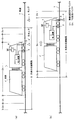
以下、本発明を実施するための最良の形態を図面に基づいて説明する。図1は、本発明に係る列車位置検知装置の概略構成図であり、図中、Tは列車イの走行する軌道であって、鉄車輪を有する列車の場合は、レールによって構成されている。なお、本発明で列車というときは、電車や気動車等の各種車両を含んでいる。 Hereinafter, the best mode for carrying out the present invention will be described with reference to the drawings. FIG. 1 is a schematic configuration diagram of a train position detection apparatus according to the present invention, in which T is a track on which train A travels, and in the case of a train having iron wheels, is constituted by a rail. In the present invention, the term “train” includes various vehicles such as trains and trains.
図1中、1は、列車イに搭載された車上装置である。この車上装置1は、CPUを中心に構成された演算処理部を有していて、列車イの速度制御や制動制御等の各種制御を司るように構成されている。そして、この車上装置1には、列車イの所定の車輪の車軸に接続され、この車軸の回転に伴ってパルス状の出力信号を出力する速度発電機、いわゆるタコジェネレータ(以下、「TG」という。)2と、列車イの先頭下部に設けられている車上子3が接続されていて、速度発電機式列車位置検知装置(以下、「TG式列車位置検知装置」という。)の機能を有している。
In FIG. 1,
図1中、aは地上子であって、軌道Tの所定位置に設置されていて、その設置位置を示す所定の位置情報を車上(列車イ)に向けて送出できるように構成されている。したがって、列車イの進行に伴って車上子3と地上子aとが対向すると、車上装置1は、車上子3を介して地上子aの設置位置情報を入力して軌道Tにおける列車イの絶対位置を入手することができる。
In FIG. 1, a is a ground element, which is installed at a predetermined position on the track T, and is configured so that predetermined position information indicating the installation position can be transmitted toward the vehicle (train A). . Accordingly, when the vehicle upper 3 and the ground child a face each other as the train A progresses, the on-
図1中、4は列車イに搭載され、車上装置1に接続された車上無線機であって、地上の所定位置に設けられている沿線無線機5との間で無線通信ができるように構成されている。すなわち、この列車イは、周知の列車に搭載された車上無線機及び地上に設けられた地上無線機間の無線の伝播時間に基づいて列車位置を検知する無線測距式列車位置検知装置が設備されている。なお、無線測距式列車位置検知装置で得られた列車位置情報は、列車イ側で持つこともできるし、沿線無線機5を制御している図示しない地上装置側でもつこともできるし、あるいは両方で持つこともできる。列車位置情報を車上側、地上側又は両方のいずれで持つかは列車の制御方式によって決められるが、ここでは、説明を簡単にするために、TG式列車位置検知装置で検知された列車位置情報も無線測距式列車位置検知装置で検知された列車位置情報も車上装置1で管理されるものとして説明する。
In FIG. 1,
図1中、破線で示される車上装置1´、TG2´、車上子3´及び車上無線機4´の各機器は、列車イが折り返し点で運転方向が図1に矢印で示される方向(図1では、列車イは左側から右側に進行するように示されている。)と反対方向になり、運転台が変換されたときに働く機器である。このように、列車イには、進行方向別に機器が設けられているが、以後、説明を簡単にするために、列車イに搭載される機器は1個として説明する。また、地上子a及び沿線無線機5は、図1中に各1個しか示されていないが、実際は、軌道Tに沿って所定の間隔を保って複数個設けられている。
In FIG. 1, the on-
次に、図2〜図4を用いて、上記構成からなる無線測距式列車位置検知装置及びTG式列車位置検知装置を備えた列車イの列車位置検知の制御動作について説明する。 Next, the control operation of the train position detection of the train A provided with the wireless ranging train position detection device and the TG type train position detection device having the above-described configuration will be described with reference to FIGS.
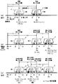
先ず、図2(a)を用いて説明すると、図2(a)中、D0は列車イの列車長を示し、D1は無線測距式列車位置検知装置における検知誤差に基づく長さを示し、また、D2はTG式列車位置検知装置における検知誤差に基づく長さを示している。したがって、列車イの列車長D0に各検知装置の検知誤差に基づく長さを列車イの進行方向側及びその進行方向と反対側にそれぞれ加えた長さを、軌道Tにおける列車イの在線範囲Dとしたときは、少なくとも列車イの前方側(進行方向側)の防護を図ることができるとともに、その列車イの後方側(進行方向と反対側)の防護を図ることができ、列車イの安全運行を図ることができる。なお、上述のように、D1は、無線測距式列車位置検知装置で算出された列車位置の誤差による安全バッファであるから、以後、「無線測距安全バッファ」といい、D2は、TG式列車位置検知装置で算出された列車位置の誤差による安全バッファであるから、以後、「TG安全バッファ」という。 First, using FIG. 2 (a), in FIG. 2 (a), D 0 indicates the train length of train A, and D 1 indicates the length based on the detection error in the wireless ranging train position detection device. shows, also, D 2 denotes the length based on the detection error in the TG expression train position detection device. Therefore, the length obtained by adding the length based on the detection error of each detector to the train length D 0 of the train A on the traveling direction side of the train A and on the opposite side of the traveling direction, respectively, When D, it is possible to protect at least the front side (traveling direction side) of train A, and to protect the rear side (opposite direction of traveling) of train A. Safe operation is possible. As described above, since D 1 is a safety buffer due to an error in the train position calculated by the radio ranging train position detection device, hereinafter, it is referred to as a “radio ranging safety buffer”, and D 2 is Since this is a safety buffer due to an error in the train position calculated by the TG type train position detection device, it is hereinafter referred to as a “TG safety buffer”.
図2(a)中、a´は、本発明の仮基準位置に相当する仮地上子であって、車上装置1が無線測距位置に従って設定した架空の地上子である。この仮地上子a´は、無線測距式列車位置検知装置によって設定されるように構成されている。
In FIG. 2A, a ′ is a temporary ground element corresponding to the temporary reference position of the present invention, and is an imaginary ground element set by the on-
上述のように、無線測距式列車位置検知装置によって仮地上子a´を設定した場合は、この仮地上子a´を基点にTG2により列車イの走行距離を算出できるので、無線測距式列車位置検知装置がトンネル等によって不調を来たしたときでも列車イの位置を検知することが可能となる。また、この仮地上子a´の設置位置は、無線測距式列車位置検知装置の検知誤差が、列車イの走行距離によって影響を受けないので正確な列車位置に設定できる特長を有している。
As described above, when the temporary ground element a ′ is set by the wireless distance measuring train position detecting device, the travel distance of the train A can be calculated from the temporary ground element a ′ by the
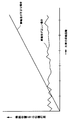
すなわち、無線測距式列車位置検知装置の検知誤差は、これまでの多くの実験結果から±数m(例えば±4.5m)の範囲であり、これに対し、TG式列車位置検知装置の検知誤差は、図3に示されるように、空転,滑走による誤差の他に車輪径の設定違いによる誤差が累積され、列車イの走行距離に応じて大きくなる性質を有している。 In other words, the detection error of the radio ranging train position detection device is within a range of ± several meters (for example, ± 4.5 m) from many experimental results so far, whereas the detection error of the TG type train position detection device is As shown in FIG. 3, the error has the property of accumulating errors due to difference in wheel diameter setting in addition to errors due to idling and sliding, and increases according to the travel distance of train A.
図2(b)は、列車イの車上子3が実際に設置されている地上子aに対向し、その地上子aから列車イの絶対位置の情報を得た状態を示している。この場合、車上装置1は、仮地上子a´よりも精度の高い位置情報が地上子aから得られるので、無線測距安全バッファD1を取り除くことができ、列車イの在線範囲DはTG安全バッファD2のみを考慮すればよくなることを示している。
FIG. 2 (b) shows a state in which the vehicle upper 3 of the train A faces the ground element a where the train is actually installed, and information on the absolute position of the train A is obtained from the ground element a. In this case, since the on-
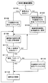
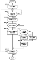
以下、図4のフローチャートを用いて列車位置検知制御動作について説明する。車上の電源が投入され、列車イが軌道Tを走行しようとしているものとする。そして、その列車イがTG2の基準点となる地上子aに差しかかっていない図1に示される状態において(ステップ100否定。以下、ステップを「S」とする。)、その列車イの軌道Tにおける在線状態は、図2(a)に示されるように、列車長D0の前後に無線測距安全バッファD1及びTG安全バッファD2をそれぞれ設けた状態とされる(S102)。したがって、列車イの前方及び後方は、十分な安全バッファによりそれぞれ防護される。そして、列車イの車上装置1では、無線測距式列車位置検知装置から列車位置が得られると仮地上子a´を設定し、その仮地上子a´の位置がTG式列車位置検知装置の基準とされて列車追跡が行われる(S104、S108)。
Hereinafter, the train position detection control operation will be described with reference to the flowchart of FIG. It is assumed that the power on the vehicle is turned on and the train A is going to travel on the track T. Then, in the state shown in FIG. 1 in which the train A does not reach the ground element a serving as the reference point of TG2 (No in step 100; hereinafter, the step is referred to as “S”), the track T of the train A As shown in FIG. 2A, the standing line state in FIG. 2 is a state in which a radio ranging safety buffer D 1 and a TG safety buffer D 2 are provided before and after the train length D 0 (S102). Therefore, the front and rear of train A are protected by sufficient safety buffers, respectively. In the on-
列車イの走行により車上子3が基準点となる地上子aに対向して通信が確立すると(S110肯定)、その地上子aからは列車イの絶対位置情報が得られるので、列車イの軌道Tにおける在線状態は、図2(b)に示されるように、列車長D0の前後にTG安全バッファD2を設けた状態とされ(S112否定、S116)、基準点(地上子aの設置位置)を基に列車追跡が行われる(S114、S108)。そして、さらに列車イの走行が進み、図1では示されていない次の地上子に車上子3が対向したときは、基準点の更新が行われる(S110肯定〜S116)。
When communication is established while the vehicle upper 3 is opposed to the ground child a serving as a reference point by the traveling of the train (S110 affirmative), the absolute position information of the train a is obtained from the ground child a. on-rail state of track T, as shown in FIG. 2 (b), is a state in which a TG safety buffer D 2 before and after the train length D 0 (S112 negative, S116), the reference point (the ground element a Train tracking is performed based on (installation position) (S114, S108). Further, when the train A further travels and the vehicle
上述のように、無線測距式列車位置検知装置とTG式列車位置検知装置とを併用したときは、基準点となる地上子が存在しなくとも、その無線測距式列車位置検知装置で検知された位置に仮地上子a´を設定し、以後、TG式列車位置検知装置で列車イを追跡することができる特長がある。 As described above, when a radio distance measuring train position detection device and a TG type train position detection device are used in combination, even if there is no ground element serving as a reference point, detection is performed by the wireless distance measuring train position detection device. The temporary ground element a ′ is set at the set position, and thereafter, the train TG can be tracked by the TG type train position detecting device.
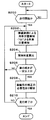
図5のフローチャートは、車輪径の補正の必要性の有無を判定するための制御動作を示している。この判定は、無線測距式列車位置検知装置の特性及びTG式列車位置検知装置の特性を活かして、TG式列車位置検知装置の計算の基となる列車イの車輪径値の正当性を判定している。 The flowchart of FIG. 5 shows a control operation for determining whether or not the wheel diameter needs to be corrected. This determination uses the characteristics of the wireless ranging train position detection device and the characteristics of the TG train position detection device to determine the legitimacy of the wheel diameter value of train A, which is the basis for the calculation of the TG train position detection device. is doing.
すなわち、上述の図3に示されるように、無線測距式列車位置検知装置による検知誤差は、列車イの走行距離に関係なく所定範囲にあり、これに対し、TG式列車位置検知装置の検知誤差は、設定した車輪径が不適切である場合、列車イの走行距離に比例して大きくなる性質を有している。この走行距離に比例した検知誤差は、車輪が摩耗等により変化し、当初の値より車輪径が小さくなることにより発生するので、TG式列車位置検知装置には、車輪径を一定きざみ(例えば5mmきざみ)で設定する設定スイッチが設けられている。なお、列車の通常の車輪径は750mmである。 That is, as shown in FIG. 3 described above, the detection error by the radio distance measuring train position detection device is within a predetermined range regardless of the travel distance of the train A, whereas the detection by the TG type train position detection device. The error has a property of increasing in proportion to the travel distance of the train A when the set wheel diameter is inappropriate. The detection error proportional to the travel distance is generated when the wheel changes due to wear or the like, and the wheel diameter becomes smaller than the initial value. A setting switch is provided for setting in steps. In addition, the normal wheel diameter of a train is 750 mm.
上述の説明から明らかなように、列車イに無線測距式列車位置検知装置及びTG式列車位置検知装置を備えた場合は、TG式列車位置検知装置の計算の基となる車輪径の設定が正しく設定されているかを容易に知ることができる。すなわち、車上装置1には、列車イの走行が開始されると(S200肯定)、無線測距式列車位置検知装置とTG式列車位置検知装置とから列車位置検知データが入力され(S202)、無線測距式列車位置検知装置による列車イの所定の走行距離毎に両者の検知差が算出される(S204)。そして、一定距離進行時の差の傾きが例えば無線測距式の検知誤差の範囲(例えば±4.5m)内ならば、許容できる範囲としてそのまま列車検知が続行される(S206否定)。
As is clear from the above description, when the train a is equipped with a radio ranging train position detection device and a TG type train position detection device, the wheel diameter setting that is the basis of calculation of the TG type train position detection device is set. You can easily know whether it is set correctly. That is, when the traveling of the train A is started (Yes in S200), the train position detection data is input to the
しかしながら、上述の差が所定以上のときは(S206肯定)、車輪径の値を設定し直す必要があるので、その旨が運転台等の所定の箇所に報知される。したがって、係員は、その報知に基づいて車輪径の設定値を変更でき、以後、TG式列車位置検知装置の検知誤差を小さくすることができる。なお、上述の設定値の変更は、自動的に行うようにしてもよい。 However, when the above-described difference is greater than or equal to a predetermined value (Yes in S206), it is necessary to reset the wheel diameter value, and this is notified to a predetermined location such as the cab. Therefore, the clerk can change the setting value of the wheel diameter based on the notification, and thereafter can reduce the detection error of the TG type train position detection device. Note that the above-described setting value change may be automatically performed.
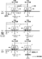
図6(a)〜(c)は、車輪の空転の発生及び滑走の発生を検出する原理を示したもので、図中、Sは、無線測距式列車位置検知装置で検知された列車イの位置を示している。以下、この位置を無線測距の基準位置Sとして説明する。この無線測距の基準位置Sの誤差は、上述したように一定の範囲内にあり、TG式列車位置検知装置のように列車イの走行距離により誤差が累積されるという性質を有していない。 6 (a) to 6 (c) show the principle of detecting the occurrence of slipping and sliding of the wheel. In the figure, S is a train event detected by the wireless ranging train position detection device. Indicates the position. Hereinafter, this position will be described as a reference position S for wireless distance measurement. The error of the reference position S of this wireless distance measurement is within a certain range as described above, and does not have the property that the error is accumulated by the travel distance of the train a as in the TG type train position detection device. .
したがって、無線測距式列車位置検知装置で列車イを走行させる場合は、列車イの前方側及び後方側にその無線測距式列車位置検知装置の無線測距安全バッファD1をそれぞれ設定すれば、列車イの前方及び後方の防護を図ることができる。 Therefore, when moving the train Lee wirelessly ranging Formula train position detection device, if the radio range finding safety buffer D 1 setting each of the wireless ranging formula train position detection device to the front side and rear side of the train Lee It is possible to protect the front and rear of train A.
図6(a)〜(c)中、Pは、TG式列車位置検知装置で検知された列車位置(以下、「TGの検知位置」という。)を示している。このTGの検知位置Pは、上述したように、無線測距の基準位置Sよりも走行距離により大きくなる性質を有している。そして、同図(a)では、このTGの検知位置Pが無線測距の基準位置Sを中心に設けられた無線測距安全バッファD1の長さ内にあり、同図(b)では、その無線測距安全バッファD1から外れた列車イの進行方向側にあって、車輪に空転が発生したことを示している。また、同図(c)では、その無線測距安全バッファD1から外れた列車イの進行方向と反対側にあって、車輪に滑走が発生したことを示している。 6A to 6C, P indicates a train position detected by the TG type train position detection device (hereinafter referred to as “TG detection position”). As described above, the detection position P of the TG has a property of becoming larger with the travel distance than the reference position S of the wireless distance measurement. In FIG. 9A, the TG detection position P is within the length of the wireless distance measurement safety buffer D 1 provided around the wireless distance measurement reference position S. In FIG. in the traveling direction of the train Lee deviated from the wireless ranging safety buffer D 1, it shows that idling the wheels has occurred. Further, in FIG. (C), be in opposite to the traveling direction of the train Lee deviated from the wireless ranging safety buffer D 1, it shows that the slide on the wheel occurs.
次に、図7のフローチャートを用いて空転・滑走の発生検出動作を説明する。先ず、列車イの車上装置1には、無線測距式列車位置検知装置で検知された列車位置が取り込まれ、その取り込まれた列車位置を基に無線測距の基準位置S及び無線測距安全バッファD1が設定される(S302)。
Next, the occurrence detection operation of idling / sliding will be described using the flowchart of FIG. First, the train position detected by the wireless distance measuring train position detection device is captured in the on-
列車イの走行が開始されると、車上装置1には、列車イの走行に伴ってTG式列車位置検知装置で検知されたTGの検知位置Pが取り込まれ(S304肯定、S306)、その検知位置Pが無線測距安全バッファD1内にあるか否かが判定される(S308)。この判定において、検知位置Pが無線測距安全バッファD1内のとき(S308肯定、図6(a)参照)、列車イが無線測距式列車位置検知装置で運転されているときはその装置で、あるいは列車イがTG式列車位置検知装置で運転されているときはその装置で運転が継続される(S310、S312否定)。
When the traveling of the train A is started, the on-
これに対して、検知位置Pが無線測距安全バッファD1から外れ、しかも列車イの前方側(先頭側)にあるときは(S308否定、S314肯定。図6(b)参照)、車輪に空転が発生したと判定されてその検知位置Pのデータは廃棄され、列車イの運行は、無線測距式列車位置検知装置で得られた列車位置(S)を用いて行われる(S316、S318)。また、検知位置Pが無線測距安全バッファD1から外れ、しかも列車イの後方側にあるときは(S314否定。図6(c)参照)、車輪に滑走が発生したと判定されてその検知位置Pのデータは廃棄され、列車イの運行は、無線測距式列車位置検知装置で得られた列車位置(S)を用いて行われる(S320、S318)。 In contrast, off detection position P from the radio ranging safety buffer D 1, yet when in front of the train Lee (top side) (S308 negation, reference affirmative. FIG 6 (b) S314), the wheel It is determined that idling has occurred and the data at the detection position P is discarded, and the operation of train A is performed using the train position (S) obtained by the wireless distance measuring train position detection device (S316, S318). ). Further, when the detection position P is out of the radio ranging safety buffer D 1 and is behind the train (S314 negative, see FIG. 6C), it is determined that the wheel has slipped and detected. The data of the position P is discarded, and the operation of the train A is performed using the train position (S) obtained by the wireless ranging train position detection device (S320, S318).
上述のように、車上装置1では、列車イの車輪の空転・滑走の発生を検出できるので、無線測距安全バッファD1を外れたTG式列車位置検知装置の列車位置を廃棄して安全運転を行うことができる。
As described above, since the on-
次に、図8及び図9を用いて列車イの車上装置1に記憶されている相対距離が初期化(リセット)されたときの検知ズレ発生防止に係る発明について説明する。先ず、図8(a)は、軌道Tを走行する列車イの車上子3が地上子aに対向し、車上子3と地上子aとの通信が確立してからの走行位置を示していて、TG式列車位置検知装置(図示していない。)が前回と今回の2回、信号を受信したときの例を示している。図8(a)中の破線で示される列車イは、車上装置1がTG式列車位置検知装置から信号を受信した初回の列車位置(図示では、前回の車上子位置)で、そのときの地上子aの設置位置である基準点P0から列車イの車上子3までの距離である相対距離は、L1として示されている。
Next, an invention relating to prevention of detection deviation when the relative distance stored in the on-
図8(a)中、実線で示される列車イは、車上装置1がTG式列車位置検知装置から2回目(図示では、今回の車上子位置)に受信したときの走行距離で、このときの相対距離は、L2として示されている。この相対距離L2は、前回の車上子3の車上子位置P1に車上装置1における演算結果である今回と前回の差分(L2−L1)を加算して求められる。すなわち、今回の車上子位置P2は、P2=P1+(L2−L1)として算出される。
In FIG. 8 (a), the train a indicated by a solid line is the travel distance when the on-
上述のように、基準点P0を基に、前回の車上子3の車上子位置P1と今回の車上装置1における演算結果(L2−L1)とから今回の車上子位置P2を算出する列車位置検知装置においては、例えば、運転台変更等の何らかの原因で電源断等が行われると(以下、運転台変更で説明する。)、2回目(図示の例では、今回の車上子位置)の相対距離L2がリセット(L2=0)されて検知ズレが発生してしまう。
As described above, based on the reference point P 0 , the current vehicle upper element is determined from the previous vehicle upper element position P 1 of the vehicle
図8(b)は、この検知ズレ発生の原因を示している。すなわち、列車イの運転台変更が行われると、相対距離L2が0にリセットされ、このリセットにより、誤った今回の車上位置P2' として、P2' =P2+(L2−L1)=P2+(0−L1)=P2−L1が算出されてしまう(図8(b)の実線で示される列車イ参照)。つまり運転台変更が行われても、本来の今回の車上位置は、P2でなければならないにもかかわらず、P2' (=P2−L1)と誤ってしまう。図8(c)は、この誤った状態を示していて、検知ズレがその後も継続されることを示している。 FIG. 8B shows the cause of this detection deviation. That is, when the cab changes trains b is performed, the relative distance L 2 is reset to 0 by the reset, 'as, P 2' wrong this car on the position P 2 = P 2 + (L 2 - L 1 ) = P 2 + (0−L 1 ) = P 2 −L 1 is calculated (see the train A shown by the solid line in FIG. 8B). That is, even if the cab is changed, the original position on the vehicle this time must be P 2 , but it is mistaken as P 2 ′ (= P 2 −L 1 ). FIG. 8C shows this erroneous state and indicates that the detection deviation is continued thereafter.
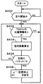
図9(a)〜(c)は、上述の原因で発生した位置ズレを防止するための説明図であり、図10のフローチャートを用いながら説明する。先ず、図9(a)は、地上子aの設置位置である基準点P0からの列車イの走行を示している。この図9(a)は、上記図8(a)と同一であるので、その説明は省略するが、列車イが走行を開始すると(S400肯定)、TG式列車位置検知装置には、TG2から位置情報が入手される。そして、その位置情報が入手されると、図8(a)を用いたときの説明と同様に、今回の車上子位置P2は、P2=P1+(L2−L1)として算出される(S402肯定、S404)。 FIGS. 9A to 9C are explanatory diagrams for preventing the positional deviation caused by the above-described cause, and will be described with reference to the flowchart of FIG. First, FIG. 9A shows the traveling of the train A from the reference point P 0 where the ground element a is installed. Since FIG. 9A is the same as FIG. 8A described above, the description thereof is omitted. However, when the train A starts to travel (Yes in S400), the TG type train position detection device includes TG2. Location information is obtained. Then, when the position information is obtained, the on-board position P 2 of this time is set as P 2 = P 1 + (L 2 −L 1 ) as in the case of using FIG. Calculated (Yes at S402, S404).
上述の走行において、列車イの走行が折り返し運転となり、運転台変更により今回受信した相対距離が初期化(リセット)されたとする(S406肯定)。このリセット時には、前回の相対距離L1及び今回の相対距離L2がリセット(L1=0,L2=0)されるとともに、列車イの車上子3に対向する軌道T上に仮想地上子a″が設定される(S408)。このときの今回の車上位置P2は、図9(b)に示されるように、P2=P2+(L2−L1)=P2+(0−0)=P2となり、本来の正しい位置となる。そして、その後、図9(c)に示されるように、列車イの折り返し運転が開始されると、設定された仮想地上子a″を前回の車上位置P0'として今回の車上位置P3が算出される。すなわち、今回の車上位置P3は、P3=P0'+(L3−0)=P0'+L3として求められる。 In the above-described travel, it is assumed that the travel of train A is a turn-back operation, and the relative distance received this time is initialized (reset) by changing the cab (Yes in S406). At the time of this reset, the previous relative distance L 1 and the current relative distance L 2 are reset (L 1 = 0, L 2 = 0), and the virtual ground is placed on the trajectory T facing the vehicle upper 3 of the train A. The child a ″ is set (S408). The current on-vehicle position P 2 at this time is P 2 = P 2 + (L 2 −L 1 ) = P 2 as shown in FIG. 9B. + (0-0) = P 2 and the original correct position is obtained, and then, as shown in FIG. The current on-vehicle position P 3 is calculated with a ″ as the previous on-vehicle position P 0 ′. That is, the current on-vehicle position P 3 is obtained as P 3 = P 0 ′ + (L 3 −0) = P 0 ′ + L 3 .
上述のように、本発明に係る列車位置検知装置においては、TG式列車位置検知装置が運転台変更等により相対距離データが初期化(リセット)されても、初期化時に仮想地上子a″を設定しているので、この仮想地上子a″を基準に相対距離を求めることができる。したがって、本発明に係る列車位置検知装置は、その後の列車位置検知にズレを生じさせないという特長を有している。 As described above, in the train position detection device according to the present invention, even if the TG type train position detection device initializes (resets) the relative distance data by changing the cab or the like, the virtual ground element a ″ is displayed at the time of initialization. Since it is set, the relative distance can be obtained based on the virtual ground element a ″. Therefore, the train position detecting device according to the present invention has a feature that no deviation occurs in subsequent train position detection.
T 軌道(レール)
a 地上子
a' 仮地上子
a'' 仮想地上子
イ 列車
1 車上装置
2 速度発電機(TG)
3 車上子
4 車上無線機
5 沿線無線機
D 在線範囲
D0 列車長
D1 無線測距安全バッファ
D2 TG安全バッファ
S 無線測距の基準位置
P0 基準点
L1,L2,L3 相対距離
T track (rail)
a Ground unit a 'Temporary ground unit a''Virtual ground
3 On-
Claims (1)
前記列車の車軸に接続された速度発電機の出力信号に基づいて前記所定の軌道における列車の走行距離を算出する走行距離算出手段と、
前記無線列車位置検知手段で検知された列車位置を所定の仮基準位置に設定する仮基準位置設定手段と、
前記仮基準位置設定手段で設定された仮基準位置から前記走行距離算出手段で算出された走行距離に基づいて前記所定の軌道における列車位置を検知する列車位置検知算出手段とからなり、
前記仮基準位置設定手段には、その仮基準位置設定手段で設定された所定の仮基準位置における前記列車の列車長に、前記無線列車位置検知手段の検知誤差に相当する長さ及び前記走行距離算出手段の検知誤差に相当する長さを加算した長さをその列車の在線範囲とする在線範囲設定手段を設け、
前記在線範囲設定手段には、列車に設けられている車上子が地上の所定の位置に設けられている列車の絶対位置を示す地上子と通信が確立したときに、前記軌道におけるその列車の在線範囲をその地上子位置における前記列車の列車長に、前記走行距離算出手段の検知誤差に相当する長ささを加算した列車長さをその列車の在線範囲とするように切り替える在線範囲切替手段を設けたこと、
を特徴とする列車位置検知装置。 Wireless train position detection that detects the train position on the predetermined track based on the radio propagation time between the onboard radio mounted on the train traveling on the predetermined track and the ground radio installed at the predetermined position on the ground Means,
A travel distance calculating means for calculating a travel distance of the train on the predetermined track based on an output signal of a speed generator connected to the axle of the train;
A temporary reference position setting means for setting the train position detected by the wireless train position detection means to a predetermined temporary reference position;
The train position detection calculating means for detecting the train position on the predetermined track based on the travel distance calculated by the travel distance calculation means from the temporary reference position set by the temporary reference position setting means,
The temporary reference position setting means includes a train length of the train at a predetermined temporary reference position set by the temporary reference position setting means, a length corresponding to a detection error of the wireless train position detection means, and the travel distance. Provided on-track range setting means that sets the length corresponding to the detection error of the calculating means to the on-line range of the train,
The on-line range setting means has an on-rail set provided on the train, when communication is established with the on-set indicating the absolute position of the train provided at a predetermined position on the ground. On-line range switching means for switching the on-line range so that the train length obtained by adding the length corresponding to the detection error of the travel distance calculating means to the train length of the train at the ground position is set as the on-line range of the train. Established
A train position detecting device characterized by.
Priority Applications (1)
| Application Number | Priority Date | Filing Date | Title |
|---|---|---|---|
| JP2006166922A JP4861069B2 (en) | 2006-06-16 | 2006-06-16 | Train position detector |
Applications Claiming Priority (1)
| Application Number | Priority Date | Filing Date | Title |
|---|---|---|---|
| JP2006166922A JP4861069B2 (en) | 2006-06-16 | 2006-06-16 | Train position detector |
Related Child Applications (1)
| Application Number | Title | Priority Date | Filing Date |
|---|---|---|---|
| JP2011186582A Division JP5412482B2 (en) | 2011-08-29 | 2011-08-29 | Train position detector |
Publications (2)
| Publication Number | Publication Date |
|---|---|
| JP2007331629A JP2007331629A (en) | 2007-12-27 |
| JP4861069B2 true JP4861069B2 (en) | 2012-01-25 |
Family
ID=38931507
Family Applications (1)
| Application Number | Title | Priority Date | Filing Date |
|---|---|---|---|
| JP2006166922A Active JP4861069B2 (en) | 2006-06-16 | 2006-06-16 | Train position detector |
Country Status (1)
| Country | Link |
|---|---|
| JP (1) | JP4861069B2 (en) |
Cited By (2)
| Publication number | Priority date | Publication date | Assignee | Title |
|---|---|---|---|---|
| CN103842236A (en) * | 2011-09-30 | 2014-06-04 | 日本信号株式会社 | Train control system |
| CN103857577A (en) * | 2011-09-30 | 2014-06-11 | 日本信号株式会社 | Train control system |
Families Citing this family (13)
| Publication number | Priority date | Publication date | Assignee | Title |
|---|---|---|---|---|
| JP5142744B2 (en) * | 2008-02-08 | 2013-02-13 | 日本信号株式会社 | Electronic occlusion system |
| DE102009015540A1 (en) * | 2009-04-01 | 2010-10-14 | Siemens Aktiengesellschaft | Method and device for speed monitoring |
| JP5877539B2 (en) | 2011-09-30 | 2016-03-08 | 日本信号株式会社 | Train control system |
| JP5806068B2 (en) | 2011-09-30 | 2015-11-10 | 日本信号株式会社 | Train control system |
| JP5759331B2 (en) * | 2011-09-30 | 2015-08-05 | 日本信号株式会社 | Train control system |
| JP5877538B2 (en) | 2011-09-30 | 2016-03-08 | 日本信号株式会社 | Train control system |
| JP5940789B2 (en) | 2011-09-30 | 2016-06-29 | 日本信号株式会社 | Train control system |
| JP5855904B2 (en) | 2011-10-31 | 2016-02-09 | 日本信号株式会社 | Train position detection system |
| JP5940795B2 (en) | 2011-11-01 | 2016-06-29 | 日本信号株式会社 | Train control system |
| JP6005411B2 (en) * | 2012-06-15 | 2016-10-12 | 日本信号株式会社 | Train position detection system |
| JP5436632B2 (en) * | 2012-07-18 | 2014-03-05 | 三菱電機株式会社 | Automatic train control device and train control method |
| CN103906668B (en) | 2012-10-26 | 2015-11-25 | 株式会社京三制作所 | Train occupation infers that ranges determination device, car-mounted device and train occupation infer range determining method |
| WO2020115793A1 (en) * | 2018-12-03 | 2020-06-11 | 三菱電機株式会社 | Onboard control device, wayside coil, wayside control device, wireless train control system, and train position correction method |
Family Cites Families (6)
| Publication number | Priority date | Publication date | Assignee | Title |
|---|---|---|---|---|
| JP2730829B2 (en) * | 1992-05-26 | 1998-03-25 | 財団法人鉄道総合技術研究所 | Wheel diameter correction method |
| JP3369776B2 (en) * | 1995-03-13 | 2003-01-20 | 株式会社東芝 | Vehicle traveling control system |
| JP2000033875A (en) * | 1998-07-17 | 2000-02-02 | Nippon Signal Co Ltd:The | Vehicle location detection device |
| JP3729748B2 (en) * | 2001-03-22 | 2005-12-21 | 三菱電機株式会社 | Automatic train control device |
| JP4244162B2 (en) * | 2003-06-06 | 2009-03-25 | 日本信号株式会社 | Train initial position setting device |
| JP2005012853A (en) * | 2003-06-16 | 2005-01-13 | Toshiba Corp | Idling slip correction processing unit |
-
2006
- 2006-06-16 JP JP2006166922A patent/JP4861069B2/en active Active
Cited By (2)
| Publication number | Priority date | Publication date | Assignee | Title |
|---|---|---|---|---|
| CN103842236A (en) * | 2011-09-30 | 2014-06-04 | 日本信号株式会社 | Train control system |
| CN103857577A (en) * | 2011-09-30 | 2014-06-11 | 日本信号株式会社 | Train control system |
Also Published As
| Publication number | Publication date |
|---|---|
| JP2007331629A (en) | 2007-12-27 |
Similar Documents
| Publication | Publication Date | Title |
|---|---|---|
| JP4861069B2 (en) | Train position detector | |
| US6915191B2 (en) | Method and system for detecting when an end of train has passed a point | |
| JP5973024B1 (en) | Position detection device | |
| CN104973093B (en) | Method for calculating the position range of a railway vehicle on a railway track and associated device | |
| JP4945286B2 (en) | Train position detector | |
| WO2009020777A1 (en) | Methods and systems for making a gps signal vital | |
| JP5412482B2 (en) | Train position detector | |
| JP2010234979A (en) | Position detecting device and position detecting method in operation security system for railroad vehicle | |
| JP2008253034A (en) | Train control device | |
| JP4818885B2 (en) | Train control device | |
| US8036784B2 (en) | System and method for verifying the integrity of a train | |
| EP2386459B1 (en) | Train location system | |
| TWI775864B (en) | position detection system | |
| JP4975053B2 (en) | Train presence detection device | |
| JP4926213B2 (en) | Train control device | |
| JP2013005588A (en) | Device and method for automatic train stop | |
| JP5398500B2 (en) | Train control device | |
| JP2017195650A (en) | Train position correction system | |
| JP2008024146A (en) | Calculation system of train door opening permission range | |
| KR20100028279A (en) | Automatic driving system for detouring danger area among automatic driving of vehicle | |
| KR101135880B1 (en) | Location measurement system and its method for railroad car using gps and imu | |
| JP4057608B2 (en) | Train control device | |
| JP5798329B2 (en) | Information processing apparatus for vehicle | |
| JP2008105485A (en) | Ground-vehicle information transmission device | |
| JP7166493B2 (en) | Forward monitoring device and forward monitoring method |
Legal Events
| Date | Code | Title | Description |
|---|---|---|---|
| A621 | Written request for application examination |
Free format text: JAPANESE INTERMEDIATE CODE: A621 Effective date: 20090610 |
|
| A977 | Report on retrieval |
Free format text: JAPANESE INTERMEDIATE CODE: A971007 Effective date: 20110310 |
|
| A131 | Notification of reasons for refusal |
Free format text: JAPANESE INTERMEDIATE CODE: A131 Effective date: 20110322 |
|
| A521 | Written amendment |
Free format text: JAPANESE INTERMEDIATE CODE: A523 Effective date: 20110520 |
|
| A131 | Notification of reasons for refusal |
Free format text: JAPANESE INTERMEDIATE CODE: A131 Effective date: 20110628 |
|
| A521 | Written amendment |
Free format text: JAPANESE INTERMEDIATE CODE: A523 Effective date: 20110829 |
|
| TRDD | Decision of grant or rejection written | ||
| A01 | Written decision to grant a patent or to grant a registration (utility model) |
Free format text: JAPANESE INTERMEDIATE CODE: A01 Effective date: 20111004 |
|
| A01 | Written decision to grant a patent or to grant a registration (utility model) |
Free format text: JAPANESE INTERMEDIATE CODE: A01 |
|
| A61 | First payment of annual fees (during grant procedure) |
Free format text: JAPANESE INTERMEDIATE CODE: A61 Effective date: 20111104 |
|
| R150 | Certificate of patent or registration of utility model |
Ref document number: 4861069 Country of ref document: JP Free format text: JAPANESE INTERMEDIATE CODE: R150 Free format text: JAPANESE INTERMEDIATE CODE: R150 |
|
| FPAY | Renewal fee payment (event date is renewal date of database) |
Free format text: PAYMENT UNTIL: 20141111 Year of fee payment: 3 |