JP4859220B2 - Luminance signal creation device, brightness signal creation method, and imaging device - Google Patents
Luminance signal creation device, brightness signal creation method, and imaging device Download PDFInfo
- Publication number
- JP4859220B2 JP4859220B2 JP2006248575A JP2006248575A JP4859220B2 JP 4859220 B2 JP4859220 B2 JP 4859220B2 JP 2006248575 A JP2006248575 A JP 2006248575A JP 2006248575 A JP2006248575 A JP 2006248575A JP 4859220 B2 JP4859220 B2 JP 4859220B2
- Authority
- JP
- Japan
- Prior art keywords
- signal
- frequency
- luminance signal
- frequency signal
- luminance
- Prior art date
- Legal status (The legal status is an assumption and is not a legal conclusion. Google has not performed a legal analysis and makes no representation as to the accuracy of the status listed.)
- Expired - Fee Related
Links
Images


Description
本発明は輝度信号作成装置及び輝度信号作成方法並びに撮像装置に関する。特にベイヤー配列の色フィルタを用いた撮像素子により得られる信号から輝度信号を作成する装置及び方法、並びにそれらを用いる撮像装置に関する。 The present invention relates to a luminance signal generation apparatus, a luminance signal generation method, and an imaging apparatus. In particular, the present invention relates to an apparatus and method for creating a luminance signal from a signal obtained by an image sensor using a Bayer color filter, and an imaging apparatus using them.
CCDイメージセンサやCMOSイメージセンサのような、光量を検出可能な撮像素子を用いてカラー画像を作成するため、色フィルタを透過させた光を撮像素子に入射させる構成が一般に用いられている。 In order to create a color image using an image sensor that can detect the amount of light, such as a CCD image sensor or a CMOS image sensor, a configuration in which light transmitted through a color filter is incident on the image sensor is generally used.
色フィルタには、用いる色の種類や、画素毎に割り当てる色の配列などによって様々な種類が存在するが、色の種類は原色(赤、緑、青)又は補色(シアン、マゼンタ、イエロー)が、色配列についてはベイヤー配列がそれぞれ広く用いられている。 There are various types of color filters depending on the type of color used and the arrangement of colors assigned to each pixel. The color types are primary colors (red, green, blue) or complementary colors (cyan, magenta, yellow). For the color arrangement, the Bayer arrangement is widely used.
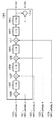
図18は、原色ベイヤー配列の1単位を示す図である。実際には、同様の配列が撮像素子の画素数に応じて繰り返される。Rが赤、G1及びG2は緑、Bが青である。 FIG. 18 is a diagram showing one unit of the primary color Bayer array. Actually, the same arrangement is repeated according to the number of pixels of the image sensor. R is red, G1 and G2 are green, and B is blue.
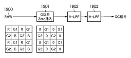
図19は、図18に示す原色ベイヤー配列の色フィルタを用いて輝度信号を作成する従来方法のうち、緑(G)信号のみから輝度信号を作成するOutOfGreen方式を説明する図である。 FIG. 19 is a diagram for explaining an OutOfGreen method for creating a luminance signal from only a green (G) signal, among conventional methods for creating a luminance signal using the color filters of the primary color Bayer array shown in FIG.
まず、撮像素子の出力をデジタル化したRAW信号1900のうち、G画素以外の値を0とする(1901)。次に、垂直方向の帯域を制限するローパスフィルタ(V-LPF)処理(1902)及び水平方向の帯域を制限するローパスフィルタ(H-LPF)処理(1903)を行い、輝度信号を得る。以下、OutOfGreen方式で得られる輝度信号をOG信号という。
First, in the RAW
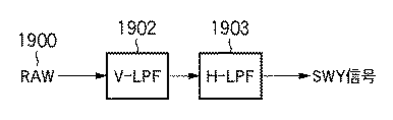
また、図18に示す原色ベイヤー配列の色フィルタを用いて輝度信号を作成する従来方法の別の例として、RGB全ての画素を用いて輝度信号を作成するSWY方式がある。
図20は、SWY方式を説明する図である。
SWY方式は、OutOfGreen方式における、G画素以外の値を0とする処理(1901)を行なわずに輝度信号を得る方式である。以下、SWY方式で得られる輝度信号をSWY信号という。
As another example of a conventional method for creating a luminance signal using a color filter with a primary color Bayer array shown in FIG. 18, there is a SWY method in which a luminance signal is created using all RGB pixels.
FIG. 20 is a diagram for explaining the SWY method.
The SWY method is a method for obtaining a luminance signal without performing the process (1901) of setting values other than G pixels to 0 in the OutOfGreen method. Hereinafter, a luminance signal obtained by the SWY method is referred to as a SWY signal.
図21は、OG信号とSWY信号の解像可能な空間周波数特性を示す図である。
x軸は被写体の水平(H)方向の周波数空間を、y軸は垂直(V)方向の周波数空間を示し、原点から遠ざかるほど空間周波数が高い。OG信号はG信号のみから輝度信号を作成するため、水平及び垂直方向の解像限界はナイキスト周波数(軸上、π/2)に等しい。しかし、斜め方向は画素が存在しないラインが存在するため、斜め方向の限界解像周波数は水平垂直にくらべ低く、結果として図のひし形領域2100の内部が解像可能な空間周波数となる。
FIG. 21 is a diagram showing resolvable spatial frequency characteristics of the OG signal and the SWY signal.
The x-axis indicates the frequency space in the horizontal (H) direction of the subject, the y-axis indicates the frequency space in the vertical (V) direction, and the spatial frequency increases as the distance from the origin increases. Since the OG signal creates a luminance signal only from the G signal, the resolution limit in the horizontal and vertical directions is equal to the Nyquist frequency (on the axis, π / 2). However, since there are lines in which no pixels exist in the oblique direction, the limit resolution frequency in the oblique direction is lower than that in the horizontal and vertical directions. As a result, the inside of the
一方、SWY信号は、全ての画素を用いて信号をつくるため、被写体が無彩色の場合、図のような正方形領域2101が解像可能な空間周波数となる。しかしながら、例えば赤い被写体においては、R画素以外からの画素からは輝度信号が出力されないため、無彩色被写体に比べ、4分の1の範囲2102でしか解像しない。
On the other hand, since the SWY signal is generated using all pixels, when the subject is achromatic, the
特許文献1では、図21における、OG信号の斜め領域2103については、SWY信号で置換する方法を提案している。但し、有彩色被写体はSWY信号の解像限界周波数が下がるため、斜め領域が無彩色被写体である場合に限り、OG信号をSWY信号に置換する。その後、作成された輝度信号を用いてエッジ強調成分を検出し、輝度信号に加算して最終輝度信号を作成する。
一方、特許文献2では、被写体の角度に応じて、予め用意した複数の補間フィルタを使い分けて輝度信号を作成し、その後エッジ強調を行なって最終輝度信号を作成する方法を提案している。
On the other hand,
また、特許文献3では、特許文献1と同様、OG信号とSWY信号を、被写体の色相及び彩度に応じて加重加算する方法を提案している。具体的には、低彩度被写体被写体はSWY信号、高彩度被写体かつMg(マゼンタ)、G(グリーン)の被写体にはSWY信号を使用し、その他有彩色被写体についてはOG信号を使用する。その後、MIX信号でエッジ強調成分を算出し、別途作成した輝度信号に加算して最終輝度信号を作成する。
しかしながら、特許文献1記載の手法を原色ベイヤー配列の色フィルタを用いて得た信号に適用する場合、図20に示した方法で作成したSWY信号を用いると、斜め45度及び135度付近に偽解像信号(折り返し歪み)が発生する弊害があった。これは、図20の方法では、H方向及びV方向のみ帯域制限しているため、斜め45度及び135度方向における帯域制限が十分でないことによるものと考えられる。
However, when the method described in
また、有彩色被写体についてはOG信号を用いるので、有彩色被写体についての斜め方向の解像度は向上しない。更に、OG信号の一部をSWY信号に置換えた後の輝度信号でエッジ強調信号を作成すると、OG信号とSWY信号の切り替わり部分が強調され、不自然なテクスチャーが発生しやすい。 Further, since the OG signal is used for the chromatic subject, the resolution in the oblique direction for the chromatic subject is not improved. Furthermore, when an edge emphasis signal is created with a luminance signal after part of the OG signal is replaced with the SWY signal, the switching portion between the OG signal and the SWY signal is emphasized, and an unnatural texture is likely to occur.
また、特許文献2の手法は、被写体の確度に応じた複数の補間フィルタを予め用意し、かつ保持する必要がある。色の構成を例えばNTSC−RGB空間とすると、輝度信号構成比であるR:G:B=3:6:1を維持する補間フィルタを準備する必要がある。その結果、フィルタの係数が限定され、被写体の角度に最適なフィルタ処理が行えないという問題がある。また、特許文献1と同様、複数の補間方法で算出された輝度信号を混在させてからエッジ強調を実施しているため、算出方法の異なる輝度信号の微妙な切り替わりが強調されてしまう。
In the method of
また、特許文献3の手法では、OG信号の代わりにSWY信号を使用するのがMgとGの被写体であるため、有彩色被写体のうちMgとG以外の被写体の解像度は向上しない。更に、特許文献1及び特許文献2の手法と同様、複数の手法で算出された輝度信号を加重加算してからエッジ強調を実施しているため、手法の切り替わり部分が強調されてしまう。
Further, in the technique of
本発明はこのような従来技術の問題点に鑑みてなされたものである。本発明の目的は、斜め方向成分における折り返し歪みの発生を抑制可能な輝度信号の作成方法及び装置を提供することにある。 The present invention has been made in view of such problems of the prior art. An object of the present invention is to provide a method and apparatus for creating a luminance signal capable of suppressing the occurrence of aliasing distortion in an oblique direction component.
上述の目的は、原色ベイヤー配列の色フィルタを備えた撮像素子によって得られた被写体の信号から、輝度信号を作成する輝度信号作成装置であって、撮像素子のG画素の信号のみから作成した第1の輝度信号を用いて第1の高周波信号を作成する第1の高周波信号作成手段と、撮像素子の全色画素の信号から作成した第2の輝度信号を用いて第2の高周波信号を作成する第2の高周波信号作成手段と、被写体の信号の空間周波数に応じて第1の高周波信号と第2の高周波信号を加重加算し第3の高周波信号を作成する加重加算手段と、第1の輝度信号と第3の高周波信号を加算し、第3の輝度信号を作成する加算手段とを有し、加重加算手段は、第1の輝度信号に、空間周波数領域において45度方向のバンドパスフィルタ処理を行った第1のバンドパス信号と、第1の輝度信号に、空間周波数領域において135度方向のバンドパスフィルタ処理を行った第2のバンドパス信号との差の絶対値が大きいほど、第3の高周波信号における第2の高周波信号の比率を高くする加重加算を行なうことを特徴とする輝度信号作成装置によって達成される。
The above-described object is a luminance signal generation device that generates a luminance signal from a signal of an object obtained by an image sensor having a color filter with a primary color Bayer array, and is a first image signal generated from only a G pixel signal of the image sensor . A first high-frequency signal generating means for generating a first high-frequency signal using one luminance signal, and a second high-frequency signal using a second luminance signal generated from signals of all the color pixels of the image sensor Second high-frequency signal creating means, weighted addition means for creating a third high-frequency signal by weighted addition of the first high-frequency signal and the second high-frequency signal according to the spatial frequency of the signal of the subject , adding the luminance signal and the third high-frequency signal, and an adding means for creating a third luminance signal and chromatic, weighted addition means, the first luminance signal, a band-
また、上述の目的は、原色ベイヤー配列の色フィルタを備えた撮像素子によって得られた被写体の信号から、撮像素子の各画素の輝度信号を作成する輝度信号作成装置であって、撮像素子のG画素のみから作成した第1の輝度信号を用いて第1の高周波信号を作成する第1の高周波信号作成手段と、撮像素子の全色画素の信号の水平、垂直及び45度方向の帯域を制限した第2の輝度信号を用いて第2の高周波信号を作成する第2の高周波信号作成手段と、撮像素子の全色画素の信号の水平、垂直及び135度方向の帯域を制限した第3の輝度信号を用いて第3の高周波信号を作成する第3の高周波信号作成手段と、第2及び第3の高周波信号の一方を選択する選択手段と、第1の高周波信号と、第2及び第3の高周波信号のうち選択手段が選択した一方とを加重加算し、第4の高周波信号を作成する加重加算手段と、第1の輝度信号と第4の高周波信号とを加算し、第4の輝度信号を出力する加算手段と、を有し、選択手段は、第1の輝度信号の45度方向の帯域を制限した信号の絶対値が第1の輝度信号の135度方向の帯域を制限した信号の絶対値より大きければ第2の高周波信号を、小さければ第3の高周波信号を選択することを特徴とする輝度信号作成装置によっても達成される。 Further, the above object is, from the signals of the subject obtained by the image pickup element having a primary color Bayer pattern type of color filter array, a luminance signal creating apparatus for creating a luminance signal of each pixel of the image sensor, G of the image sensor First high-frequency signal generating means for generating a first high-frequency signal using a first luminance signal generated from only pixels, and the horizontal, vertical, and 45 degree direction bands of all color pixel signals of the image sensor are limited. Second high-frequency signal generating means for generating a second high-frequency signal by using the second luminance signal, and a third that limits the horizontal, vertical, and 135-degree band of the signals of all the color pixels of the image sensor . Third high-frequency signal generating means for generating a third high-frequency signal using the luminance signal, selection means for selecting one of the second and third high-frequency signals, the first high-frequency signal, the second and second Of the three high-frequency signals, the selection means The one and the weighted sum-option, a weighted addition means for generating a fourth high-frequency signal, adding means first adds the luminance signal and the fourth high-frequency signal, and outputs a fourth luminance signal, have a, selection means, second greater than the absolute value of the signal absolute value of the first signal with a limited band of 45 degree direction of the luminance signal is band-limits the 135-degree direction of the first luminance signal This is also achieved by a luminance signal generating apparatus characterized by selecting a third high frequency signal if it is small .
また、上述の目的は、原色ベイヤー配列の色フィルタを備えた撮像素子によって得られた被写体の信号から、輝度信号を作成する輝度信号作成方法であって、撮像素子のG画素の信号のみから作成した第1の輝度信号を用いて第1の高周波信号を作成する第1の高周波信号作成工程と、撮像素子の全色画素の信号から作成した第2の輝度信号を用いて第2の高周波信号を作成する第2の高周波信号作成工程と、被写体の信号の空間周波数に応じて第1の高周波信号と第2の高周波信号を加重加算し第3の高周波信号を作成する加重加算工程と、第1の輝度信号と第3の高周波信号を加算し、第3の輝度信号を作成する加算工程とを有し、加重加算工程は、第1の輝度信号に、空間周波数領域において45度方向のバンドパスフィルタ処理を行った第1のバンドパス信号と、第1の輝度信号に、空間周波数領域において135度方向のバンドパスフィルタ処理を行った第2のバンドパス信号との差の絶対値が大きいほど、第3の高周波信号における第2の高周波信号の比率を高くする加重加算を行なうことを特徴とする輝度信号作成方法によっても達成される。 The above-described object is a luminance signal generation method for generating a luminance signal from a signal of an object obtained by an image sensor having a primary color Bayer array color filter, which is generated only from a signal of a G pixel of the image sensor. A first high-frequency signal generating step of generating a first high-frequency signal using the first luminance signal, and a second high-frequency signal using the second luminance signal generated from signals of all the color pixels of the image sensor A second high-frequency signal generating step for generating the first high-frequency signal, a weighted addition step for generating a third high-frequency signal by weighted addition of the first high-frequency signal and the second high-frequency signal according to the spatial frequency of the signal of the subject , plus one of the luminance signal and the third high-frequency signal, and an adding step of generating a third luminance signal and chromatic, weighted addition process, the first luminance signal, 45 degree direction of the band in the spatial frequency domain Perform path filtering The larger the absolute value of the difference between the first bandpass signal and the second luminance band signal obtained by subjecting the first luminance signal to bandpass filtering in the direction of 135 degrees in the spatial frequency domain, the third This can also be achieved by a luminance signal generation method characterized by performing weighted addition for increasing the ratio of the second high-frequency signal to the high-frequency signal .
また、上述の目的は、原色ベイヤー配列の色フィルタを備えた撮像素子によって得られた被写体の信号から、輝度信号を作成する輝度信号作成方法であって、撮像素子のG画素のみから作成した第1の輝度信号を用いて第1の高周波信号を作成する第1の高周波信号作成工程と、撮像素子の全色画素の信号の水平、垂直及び45度方向の帯域を制限した第2の輝度信号を用いて第2の高周波信号を作成する第2の高周波信号作成工程と、撮像素子の全色画素の信号の水平、垂直及び135度方向の帯域を制限した第3の輝度信号を用いて第3の高周波信号を作成する第3の高周波信号作成工程と、第2及び第3の高周波信号の一方を選択する選択工程と、第1の高周波信号と、第2及び第3の高周波信号のうち選択工程が選択した一方とを加重加算し、第4の高周波信号を作成する加重加算工程と、第1の輝度信号と第4の高周波信号とを加算し、第4の輝度信号を出力する加算工程とを有し、選択工程は、第1の輝度信号の45度方向の帯域を制限した信号の絶対値が第1の輝度信号の135度方向の帯域を制限した信号の絶対値より大きければ第2の高周波信号を、小さければ第3の高周波信号を選択することを特徴とする輝度信号作成方法によっても達成される。 Another object of the present invention is to provide a luminance signal generation method for generating a luminance signal from a signal of a subject obtained by an image sensor having a primary color Bayer array color filter, which is generated only from G pixels of the image sensor . A first high-frequency signal generating step for generating a first high-frequency signal using one luminance signal, and a second luminance signal in which the horizontal, vertical, and 45-degree band bands of all color pixel signals of the image sensor are limited And a second high-frequency signal generating step for generating a second high-frequency signal using the first and third luminance signals in which the horizontal, vertical, and 135-degree bandwidths of the signals of all color pixels of the image sensor are limited. A third high-frequency signal creating step for creating three high-frequency signals, a selection step for selecting one of the second and third high-frequency signals, the first high-frequency signal, and the second and third high-frequency signals. Add one selected by the selection process Adding to the weighted addition step of generating a fourth high-frequency signal, a first adds the luminance signal and the fourth high-frequency signal, possess an adding step of outputting a fourth luminance signal, selection process If the absolute value of the first luminance signal with the band limited in the 45 degree direction is larger than the absolute value of the first luminance signal with the band limited in the 135 degree direction, the second high frequency signal is smaller. It is also achieved by a luminance signal generation method characterized by selecting a third high-frequency signal .
このような構成により、本発明によれば、輝度信号の斜め方向における折り返し歪みを抑制させることが可能になる。 With such a configuration, according to the present invention, it is possible to suppress the aliasing distortion of the luminance signal in the oblique direction.
以下、図面を参照して、本発明をその好適な実施形態に基づき詳細に説明する。
図1は本発明の第1の実施形態に係る輝度信号作成装置の構成例を示すブロック図である。本実施形態の輝度信号作成装置は、原色ベイヤー配列の色フィルタを備える撮像素子を用いる撮像装置において、所謂現像処理等の信号処理を行なう信号処理回路において好適に実現可能である。
Hereinafter, the present invention will be described in detail based on preferred embodiments with reference to the drawings.
FIG. 1 is a block diagram showing a configuration example of a luminance signal generating apparatus according to the first embodiment of the present invention. The luminance signal generation device of the present embodiment can be suitably realized in a signal processing circuit that performs signal processing such as so-called development processing in an imaging device that uses an imaging device including a color filter with a primary color Bayer array.
図示しない撮像素子から読み出され、デジタルデータ化及びホワイトバランス処理が行なわれた画像信号(以下、RAW信号100)は、OG信号作成部101及びSWY信号作成部103へ入力される。OG信号作成部101は、RAW信号100から第1の輝度信号を作成する。第1の輝度信号は、第1の高周波(エッジ)成分検出処理部102において処理され、第1の高周波信号が作成される。また、第1の輝度信号は、第2の高周波成分検出処理部104へも供給される。
An image signal (hereinafter referred to as a RAW signal 100) read out from an image sensor (not shown) and converted into digital data and subjected to white balance processing is input to the OG
また、SWY信号作成部103は、RAW信号から第2の輝度信号を作成する。第2の高周波成分検出処理部104は、第2の輝度信号から第2の高周波信号を作成する。
Further, the SWY
加重加算処理部105は、第1の高周波信号と第2の高周波信号を加算して第3の高周波信号を作成する。さらに、加算器106で第1の輝度信号(OG信号)と第3の高周波信号を加算し、最終的な輝度信号(第3の輝度信号)を作成する。
The weighted
以下、それぞれの信号処理部の詳細な説明を行なう。
(第1の高周波信号(AC_OG信号)の作成処理)
図2は、図1におけるOG信号作成部101と、第1の高周波成分検出処理部102の構成例を示す図である。
RAW信号100は、OG信号作成部101の内部で、Zero挿入回路201、DiffH信号作成回路206及びDiffV信号作成回路207にそれぞれ入力される。
Hereinafter, each signal processing unit will be described in detail.
(Process for creating first high-frequency signal (AC_OG signal))
FIG. 2 is a diagram illustrating a configuration example of the OG
The
Zero挿入回路201は、RAW信号100のうち、G以外の信号を0に置換したZero挿入G信号を作成する。垂直方向ローパスフィルタ(V-LPF)202及び第1の水平方向ローパスフィルタ(H-LPF)204は、Zero挿入G信号の垂直方向及び水平方向の帯域を制限し、それぞれGv信号及びGh信号として出力する。
第2の水平方向ローパスフィルタ(H-LPF)203は、Gv信号の水平方向の帯域を制限し、Ghv信号を出力する。
The zero
The second horizontal low-pass filter (H-LPF) 203 limits the horizontal band of the Gv signal and outputs the Ghv signal.
このようにして、Zero挿入G信号の(1)垂直方向の帯域が制限されたGv信号、(2)水平方向の帯域が制限されたGh信号、(3)垂直及び水平方向の帯域が制限されたGhv信号が作成され、いずれも加重加算回路205へ入力される。
一方、DiffH信号作成回路(DiffH)206及びDiffV信号作成回路(DiffV)207は、RAW信号100からDiffH及びDiffV信号を作成する。
In this way, (1) the Gv signal in which the vertical band is limited, (2) the Gh signal in which the horizontal band is limited, and (3) the vertical and horizontal bands of the Zero insertion G signal are limited. Ghv signals are generated and input to the
On the other hand, a DiffH signal generation circuit (DiffH) 206 and a DiffV signal generation circuit (DiffV) 207 generate DiffH and DiffV signals from the
図3は、Diff信号作成処理を説明する図であり、本実施形態において、着目画素P22におけるDiffH及びDiffV信号は以下の式1、2に従って算出される。
DiffH=|P21−P23|+|2×P22−P20−P24| (式1)
DiffV=|P12−P32|+|2×P22−P02−P42| (式2)
なお、式1及び式2における、P12〜P42は、図3中の対応画素の信号値である。
FIG. 3 is a diagram for explaining Diff signal generation processing. In this embodiment, DiffH and DiffV signals in the pixel of interest P22 are calculated according to the following equations (1) and (2).
DiffH = | P21−P23 | + | 2 × P22−P20−P24 | (Formula 1)
DiffV = | P12−P32 | + | 2 × P22−P02−P42 | (Formula 2)
In
被写体が縦縞の場合、DiffH信号が大きくなり、横縞の場合DiffV信号の値が大きくなる。減算器208は、DiffH信号からDiffV信号を減算し、DiffHV信号を出力する。加重加算係数算出回路(Tsig)209は、DiffHV信号に基づいて加重加算係数を算出し、加重加算回路205へ供給する。
When the subject is a vertical stripe, the DiffH signal is large, and when it is a horizontal stripe, the value of the DiffV signal is large. The
図4は、加重加算係数算出回路209の入出力特性例を示す図である。
横軸がDiffHV信号、縦軸が加重加算係数Tsigの値をそれぞれ示す。DiffHV≦Th0の場合は、DiffVがDiffHより大きいため横縞領域であると判定される。この場合、加重加算回路205がGh信号を100%使用するTsig値(Tsig=−128)が出力される。
FIG. 4 is a diagram illustrating an input / output characteristic example of the weighted addition
The horizontal axis indicates the DiffHV signal, and the vertical axis indicates the value of the weighted addition coefficient Tsig. When DiffHV ≦ Th0, since DiffV is larger than DiffH, it is determined that the region is a horizontal stripe region. In this case, a Tsig value (Tsig = −128) in which the
Th1<DiffHV<Th2の区間は、DiffVとDiffHが互いに近い値であるため、斜め領域と判定される。この区間では、加重加算回路205がGhv信号を100%使用するTsig値(Tsig=0)が出力される。
The section of Th1 <DiffHV <Th2 is determined as an oblique area because DiffV and DiffH are close to each other. In this section, the Tsig value (Tsig = 0) at which the
更に、DiffHV≧Th3の場合は、DiffHがDiffVより大きいため縦縞領域であると判定される。この場合には、Gv信号を100%使用するTsig値(Tsig=128)が出力される。 Further, when DiffHV ≧ Th3, since DiffH is larger than DiffV, it is determined to be a vertical stripe region. In this case, a Tsig value (Tsig = 128) using 100% of the Gv signal is output.
Th0≦DiffHV≦Th1の区間は、ー128から0まで線形的に変化するように決定されたTsigを出力する。同様に、Th2≦DiffHV≦Th3の区間は、0から128まで線形的に変化するように決定されたTsigを出力する。 In the section of Th0 ≦ DiffHV ≦ Th1, Tsig determined so as to change linearly from −128 to 0 is output. Similarly, Tsig determined so as to change linearly from 0 to 128 is output in the section of Th2 ≦ DiffHV ≦ Th3.
加重加算回路205は、このように決定されたTsigの値に基づいて、Gh信号、Gv信号、Ghv信号を以下の式3及び式4に従って加重加算し、第1の輝度信号(DC_OG信号)210を作成する。
The
Tsig>=0のとき、
![]()
![]()
![]()
![]()
加重加算回路205の出力である第1の輝度信号は、加算器106(図1)に供給される。また、第1の輝度信号は、第1の高周波成分検出処理部102へも供給される。
The first luminance signal that is the output of the
第1の高周波成分検出処理部102において、第1の輝度信号は、水平方向ローパスフィルタ(H-LPF)211及び垂直方向ローパスフィルタ(V-LPF)213へ入力される。
In the first high-frequency component
第1の輝度信号は、H−LPF211によって水平方向の帯域を制限された後、水平方向ゲイン回路(H_Gain)212によってゲイン調整される。H_Gain212の出力は水平方向のエッジ信号である。
The first luminance signal is subjected to gain adjustment by a horizontal gain circuit (H_Gain) 212 after the horizontal band is limited by the H-
同様に、第1の輝度信号は、V−LPF213によって垂直方向の帯域を制限された後、垂直方向ゲイン回路(V_Gain)214によってゲイン調整される。V_Gain214の出力は垂直方向のエッジ信号である。
なお、これ以降、エッジ信号をAC成分と記述することがある。
Similarly, the first luminance signal is subjected to the gain adjustment by the vertical gain circuit (V_Gain) 214 after the vertical band is limited by the V-
Hereinafter, an edge signal may be described as an AC component.
加算器215は、水平及び水平方向のAC成分を加算し、結果を第1の高周波信号(AC_OG信号)として出力する。第1の高周波信号は、加重加算処理部105(図1)へ供給される。
The
(第2の高周波信号(AC_SWY信号)の作成処理)
図5は、図1におけるSWY信号作成部103と、第2の高周波成分検出処理部104の構成例を示す図である。
(1)ベースとなるSWY信号作成
RAW信号100は、まず、SWY信号作成部103の垂直方向ローパスフィルタ(V-LPF)501、水平方向ローパスフィルタ(H-LPF)502によって垂直及び水平方向における帯域が制限され、汎用のSWY輝度信号が作成される。
(Process for creating second high-frequency signal (AC_SWY signal))
FIG. 5 is a diagram illustrating a configuration example of the SWY
(1) SWY signal generation as a base The
(2)AC_SWY信号の作成
原色ベイヤー配列の信号は、フィルタの分光感度の特性上、RGB三原色の色分離が良い。よって、汎用のSWY輝度信号作成に用いる水平及び垂直方向の帯域制限フィルタ501,502に加え、斜め方向についても帯域制限フィルタを適用しないと、輝度の折り返し歪みを十分抑制することができない。そこで本実施形態では、水平及び垂直方向の帯域を制限するローパスフィルタに加え、45度及び135度方向の帯域を制限する斜めLPFを設けている。そして、被写体の角度情報により、帯域制限された2種類の信号の1つを選択することを特徴としている。
(2) Creation of AC_SWY signal The primary color Bayer array signal has good color separation of the three primary colors of RGB due to the spectral sensitivity characteristics of the filter. Therefore, if the band limiting filter is not applied to the diagonal direction in addition to the horizontal and vertical
H−LPF502から出力される汎用SWY信号は、第1の2次元フィルタ(D45−LPF)503によって、45度方向の帯域が制限される。その後、45度線のエッジを検出するための2次元バンドパスフィルタ(D135−BPF)504とゲイン回路505によって、斜め45度線用エッジ強調信号(AC_45)が作成される。
The general-purpose SWY signal output from the H-
一方、汎用SWY信号は第2の2次元フィルタ(D135−LPF)506によって、135度方向の帯域が制限される。その後、135度線のエッジを検出するための2次元バンドパスフィルタ(D45−BPF)507とゲイン回路508によって、斜め135度線用エッジ強調信号(AC_135)が作成される。
On the other hand, the band of the general-purpose SWY signal in the direction of 135 degrees is limited by the second two-dimensional filter (D135-LPF) 506. Thereafter, a two-dimensional bandpass filter (D45-BPF) 507 for detecting an edge of the 135 ° line and a
AC_45信号とAC_135信号は、角度判別信号作成回路510が出力する確度判別信号(angleSigD)に応じて、セレクタ509で一方が選択される。そして、斜め方向のエッジを強調する第2の高周波信号(AC_AWY)として加重加算処理部105へ供給される。
One of the AC_45 signal and the AC_135 signal is selected by the
図6は、角度判別信号作成回路510の構成例を示すブロック図である。
角度判別信号作成回路510には、RAW信号100からOG信号作成部101が作成したDC_OG信号が入力される。45度線を強調するバンドパスフィルタ601(D135−BPF)と、絶対値回路(ABS)602により、DC_OG信号から45度線検出信号を作成する。また、135度線を強調するバンドパスフィルタ(D45−BPF)603と絶対値回路(ABS)604により、DC_OG信号から135度線検出信号を作成する。
FIG. 6 is a block diagram illustrating a configuration example of the angle determination
A DC_OG signal created by the OG
減算器605は、絶対値回路602の出力する45度線検出信号から、絶対値回路604の出力する135度線検出信号を減算する。この減算結果が、角度判別信号(angleSigD)としてセレクタ509へ供給される。セレクタ509は、角度判別信号(angleSigD)が正ならAC_45信号を、負ならAC_135信号を選択、出力する。
The
(第3の輝度信号作成処理)
加重加算処理部105は、上述したようにして作成された第1の高周波信号(AC_OG)及び第2の高周波信号(AC_SWY)を、以下の式5に従って加重加算し、第3の高周波信号(ACsig)を作成する。
(Third luminance signal creation process)
The weighted
![]()
![]()
図22は、加重加算処理部105の構成例を示す図である。本実施形態において、加重加算係数SWYUseRatioは、第1〜第5の加重加算係数SWYUseRatio_1〜SWYUseRatio_5に基づいて算出される。
FIG. 22 is a diagram illustrating a configuration example of the weighted
SWYUseRatio_1算出回路1054〜SWYUseRatio_5算出回路1058は、第1〜第5の加重加算係数SWYUseRatio_1〜SWYUseRatio_5を計算する。SWYUseRatio算出回路1059は、第1〜第5の加重加算係数SWYUseRatio_1〜SWYUseRatio_5から最終的な加重加算係数SWYUseRatioを算出する。そして、SWYUseRatio算出回路1059は、SWYUseRatio/128及び(1ーSWYUseRatio/128)を係数として乗算器1052及び1051に与える。乗算器1052及び1051は、AC_OG信号とAC_SWY信号にそれぞれ係数を乗じて出力する。乗算器1052及び1051の出力は加算器1053で加算され、加算結果はDC_OG信号と加算するため加算器106へ出力される。
The
以下、加重加算係数SWYUseRatioの算出方法を説明する。
(1)SWYUseRatio_1の算出
図17は、本実施形態の輝度信号作成装置が、図21と同様の周波数空間において、OG信号とSWY信号とをそのように使用するかを説明する図である。ここで、第1の高周波信号(AC_OG)が折り返し歪みの影響を受ける領域は斜め領域1700である。よって、領域1700を第2の高周波信号(AC_SWY)で置換すれば、折り返し歪みのない高周波信号が作成できる。よってAC_SWY信号作成時に用いた角度判別信号を用いることで、加重加算係数を算出できる。
Hereinafter, a method for calculating the weighted addition coefficient SWYUseRatio will be described.
(1) Calculation of SWYUseRatio_1 FIG. 17 is a diagram for explaining how the luminance signal generation apparatus according to the present embodiment uses the OG signal and the SWY signal in the same frequency space as in FIG. Here, a region where the first high-frequency signal (AC_OG) is affected by the aliasing distortion is an
AC_SWY算出時に角度判別信号作成回路510で作成した角度判別信号angleSigDは、正なら45度線、負なら135度線の領域を示し、絶対値が大きいほど45度および135度線に近く、小さいほど0度および90度線に近くなる特徴を持っている。
The angle discrimination signal angleSigD created by the angle discrimination
SWYUseRatio_1算出回路1054の構成例を図23に示す。SWYUseRatio_1算出回路1054は、第1の高周波成分検出処理部102から取得した角度判別信号angleSigDの絶対値を、絶対値回路(abs)701で求める。そして、図7に示すような入出力特性を有するCalSwyUse1 702を用い、SWYUseRatio_1を算出する。CalSwyUse1 702は、演算回路であっても、テーブルであっても良い。
A configuration example of the
図7において、角度判別信号angleSigの絶対値が0からTh3までの区間は、値が小さいため0度及び90度線に近く、SWYUseRatio_1=0が出力される。一方、角度判別信号angleSigの絶対値がTh4以上の区間は値が大きいため斜め線であり、第2の高周波信号に置換えるためにSWYUseRatio_1=128が出力される。ここで、128=100%を表すものとする。絶対値がTh3からTh4までの区間は0から128の範囲で線形補間された値が出力される。 In FIG. 7, the section where the absolute value of the angle determination signal angleSig is from 0 to Th3 is close to the 0 degree and 90 degree lines because the value is small, and SWYUseRatio_1 = 0 is output. On the other hand, the section where the absolute value of the angle discrimination signal angleSig is equal to or greater than Th4 is a diagonal line because the value is large, and SWYUseRatio_1 = 128 is output to replace the second high-frequency signal. Here, it is assumed that 128 = 100%. In the interval from the absolute value Th3 to Th4, a value obtained by linear interpolation in the range of 0 to 128 is output.
(2)SWYUseRatio_2の算出
図17における水平垂直領域1701は第1の高周波信号(AC_OG)を用いる。これは、OG信号が水平もしくは垂直方向の帯域を制限させる適応的OG信号であることから、水平及び垂直の両方向に帯域制限をかけるSWY信号より解像度が向上していることが理由である。
(2) Calculation of SWYUseRatio_2 The horizontal and
以下に、水平及び垂直の領域を判別する手法のひとつとして、画素差分値を利用し、この大きさによりSWYUseRatio_2を算出する方法を説明する。
画素差分値の大きさは、第1の高周波成分検出処理部102において算出されるDiffHV信号の絶対値を用いることができる。上述の通り、被写体が縦縞の場合、DiffH信号の値は大きくなりDiffV信号は0となる。また被写体が横縞の場合、DiffV信号の値は大きくなりDiffH信号は0となる。従って、DiffHとDiffVとの差であるDiffHV信号の絶対値が大きいほど、水平線か垂直線に近いことが分かる。
Hereinafter, as one of the methods for discriminating the horizontal and vertical regions, a method of using the pixel difference value and calculating SWYUseRatio_2 based on this size will be described.
The absolute value of the DiffHV signal calculated by the first high-frequency component
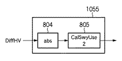
SWYUseRatio_2算出回路1055の構成例を図8に示す。SWYUseRatio_2算出回路1055は、第1の高周波成分検出処理部102から取得したDiffHV信号の絶対値を、絶対値回路(abs)804で求める。そして、図9に示すような入出力特性を有するCalSwyUse2 805を用い、SWYUseRatio_2を算出する。CalSwyUse2 805は、演算回路であっても、テーブルであっても良い。
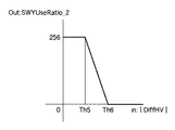
A configuration example of the
入力信号DiffHVの絶対値が0からTh5までは値が小さいため斜め線であり、SWYUserRatio_2=256が出力される。Th6以上は完全に水平及び垂直線であり、SWYUserRatio_2=0が出力される。また、Th5からTh6までの区間では線形補間された値が出力される。 When the absolute value of the input signal DiffHV is from 0 to Th5, the value is small, so it is a diagonal line, and SWYUserRatio_2 = 256 is output. Th6 and above are completely horizontal and vertical lines, and SWYUserRatio_2 = 0 is output. Also, linearly interpolated values are output in the section from Th5 to Th6.
(3)SWYUseRatio_3の算出
図17における水平及び垂直のナイキスト付近の領域(偽色領域)1702は、(2)と同じ理由から、第1の高周波信号(AC_OG)を用いるのが好ましい。ナイキスト領域は、G1とG2信号の位相のずれを検出することで判別可能である。
(3) Calculation of SWYUseRatio_3 The first high-frequency signal (AC_OG) is preferably used for the region (false color region) 1702 in the vicinity of horizontal and vertical Nyquist in FIG. 17 for the same reason as (2). The Nyquist region can be determined by detecting a phase shift between the G1 and G2 signals.
SWYUseRatio_3算出回路1056の構成例を図10に示す。
RAW信号100は、Zero挿入回路1001において、G1以外の信号に0が挿入され、Zero挿入回路1002においては、G2以外の信号に0が挿入される。水平及び垂直方向の補間のためのローパスフィルタ回路(1002,1003,1005,1006)により、0とされた画素に補間値が挿入される。
A configuration example of the
In the
次に、HLPF1003及び1006の出力は減算器1007で差分がとられ、絶対値回路1008で絶対値が算出される。この、差分絶対値が、領域を判別するsigDiffGとなる。
Next, the outputs of the
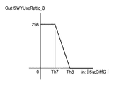
そして、図11に示すような入出力特性を有するCalSwyUse3 1009を用い、SWYUseRatio_3を算出する。CalSwyUse3 1009は、演算回路であっても、テーブルであっても良い。
Then, SWYUseRatio_3 is calculated using
入力信号sigDiffGが0からTh7までは値が小さいため斜め線であり、SWYUserRatio_3=256が出力される。一方、Th8以上は完全に水平及び垂直線であり、SWYUserRatio_3=0が出力される。また、Th7からTh8までの区間では線形補間された値が出力される。 Since the input signal sigDiffG has a small value from 0 to Th7, it is a diagonal line, and SWYUserRatio_3 = 256 is output. On the other hand, Th8 and above are completely horizontal and vertical lines, and SWYUserRatio_3 = 0 is output. Further, linearly interpolated values are output in the section from Th7 to Th8.
(4)SWYUseRatio_4の算出
図17における低周波領域1703は、第1の高周波信号(AC_OG)を用いるのが好ましい。低周波領域は、RAW信号に低周波領域を検出するフィルタを適用することで検出可能である。
(4) Calculation of SWYUseRatio — 4 It is preferable to use the first high frequency signal (AC_OG) for the
SWYUseRatio_4算出回路1057の構成例を図12に示す。
RAW信号100は、ローパスフィルタ1201及び1202により、垂直方向及び水平方向の帯域が制限される。その後、水平方向のバンドパスフィルタ(H-BPF)1203と垂直方向のバンドパスフィルタ(V-BPF)1204が別々に適用される。そして減算器1205によって、H−BPF1203の出力からV−BPF1204の出力を減算し、絶対値回路1206によって絶対値がとられ、低域検出用信号(LowF信号)として出力される。
A configuration example of the
The
そして、図13に示すような入出力特性を有するCalSwyUse4 1207を用い、SWYUseRatio_4を算出する。CalSwyUse4 1207は、演算回路であっても、テーブルであっても良い。
Then, SWYUseRatio — 4 is calculated using
入力信号LowFが0からTh9までは値が小さいため高周波領域であり、SWYUserRatio_4=256が出力される。一方、Th10以上は低周波領域であり、SWYUserRatio_4=0が出力される。また、Th9からTh10までの区間では線形補間された値が出力される。 Since the value from 0 to Th9 of the input signal LowF is small, it is a high frequency region, and SWYUserRatio_4 = 256 is output. On the other hand, Th10 or higher is a low frequency region, and SWYUserRatio_4 = 0 is output. Further, linearly interpolated values are output in the section from Th9 to Th10.
(5)SWYUseRatio_5の算出
赤色被写体は、R画素以外の出力が0となりやすい。そのため、SWY方式で輝度信号を作成すると、ナイキスト周波数の1/2の周波数以上で折り返し歪みが発生してしまう。そのため、赤い被写体に対し、第2の高周波信号(AC_SWY)は折り返し歪みの多い信号となってしまう。よって、被写体の色を判別し、色が赤の場合、斜め領域1700であっても第1の高周波信号(AC_OG)を用いる。
(5) Calculation of SWYUseRatio_5 The red subject is likely to
SWYUseRatio_5算出回路1058の構成例を図14に示す。
色補間回路1401は、RAW信号100から予め定められた方法で画素の色補間処理を行なう。色差信号作成回路1402は、色補間結果のRGB値から、色差信号(R−Y信号及びB−Y信号)を作成する。色相角検出回路1403は、色差信号から以下の式6を用いて色相角信号θを求める。
A configuration example of the
The color interpolation circuit 1401 performs pixel color interpolation processing by a predetermined method from the

入力信号θが0からTh11までと、Th14以上は赤以外であり、SWYUserRatio_5=256が出力される。一方、Th12からTh13は赤であり、SWYUserRatio_5=0が出力される。また、Th11からTh12までの区間と、Th13からTh14までの区間では、それぞれ線形補間された値が出力される。 When the input signal θ is from 0 to Th11, Th14 and above are other than red, and SWYUserRatio_5 = 256 is output. On the other hand, Th12 to Th13 are red, and SWYUserRatio_5 = 0 is output. Also, linearly interpolated values are output in the section from Th11 to Th12 and the section from Th13 to Th14.
(6)SWYUseRatioの算出
以上のようにして算出されたSWYUseRatio_1からSWYUseRatio_5から、SWYUseRatio算出回路1059によって最終的なSWYUseRatioを算出する。
(6) Calculation of SWYUseRatio The final SWYUseRatio is calculated by the
SWYUseRatio算出回路1059の構成例を図16に示す。
SWYUseRatio_1(1600)とSWYUseRatio_2(1601)が乗算器1605で乗算された後、シフター1606により右方向に8ビットシフト演算される。シフター1606により、乗算器1605の出力値は1/256にされる。
A configuration example of the
After SWYUseRatio_1 (1600) and SWYUseRatio_2 (1601) are multiplied by
SWYUseRatio_3(1602)、SWYUseRatio_4(1603)、SWYUseRatio_5(1604)についても、それぞれ乗算器1607、1609、1611で乗算された後、シフター1608、1610、1612で1/256される。
SWYUseRatio_3 (1602), SWYUseRatio_4 (1603), and SWYUseRatio_5 (1604) are also multiplied by
これにより、0〜128の値を有するSWYUseRatioが得られる。さらに、SWYUseRatioは、除算器1613で1/128されて乗算器1052へ与えられる。また、減算器1614で(1−SWYUseRatio)を求め、乗算器1051に与える。
Thereby, SWYUseRatio having a value of 0 to 128 is obtained. Further, SWYUseRatio is 1/128 by
乗算器1051、1052は、AC_OG信号とAC_SWY信号にそれぞれ係数を乗じて出力する。この出力を加算器1053で加算することで、式(5)のACsig(第3の高周波信号)が得られる。
以上説明したように、本実施形態によれば、OG信号から作成した第1の高周波信号とSWY信号から作成した第2の高周波信号を加重加算し、ベースとなる輝度信号であるDC_OG信号に加算する。従って、従来のように、算出方法の異なる輝度信号の切り替わり点が、後段で行なわれるエッジ強調処理によって強調されることがない。 As described above, according to the present embodiment, the first high-frequency signal created from the OG signal and the second high-frequency signal created from the SWY signal are weighted and added to the DC_OG signal that is the base luminance signal. To do. Therefore, unlike the prior art, the switching point of the luminance signal having a different calculation method is not enhanced by the edge enhancement processing performed in the subsequent stage.
更に、本実施形態では、垂直及び水平方向のみならず、45度及び135度方向に対しても帯域制限したSWY信号を用いて第2の高周波信号を作成している。これにより、従来のSWY信号で発生する、斜め方向の輝度折りかえりを抑制することが可能となる。 Furthermore, in the present embodiment, the second high-frequency signal is generated using the SWY signal that is band-limited not only in the vertical and horizontal directions but also in the 45-degree and 135-degree directions. As a result, it is possible to suppress the luminance reversal in the oblique direction that occurs with the conventional SWY signal.
更に、本実施形態では、第1の高周波信号と第2の高周波信号の使用率を決定する斜め線判別信号を、OG信号を用いて検出する。そのため、例えば赤色被写体領域は斜め領域でもOG信号が使われるようになり、斜め領域でSWY信号を使用した際に赤被写体で生じやすい折り返し歪みを抑制することが可能となる。 Furthermore, in the present embodiment, an oblique line discrimination signal that determines the usage rate of the first high-frequency signal and the second high-frequency signal is detected using the OG signal. Therefore, for example, an OG signal is used in a red subject area even in an oblique region, and aliasing distortion that is likely to occur in a red subject when the SWY signal is used in the oblique region can be suppressed.
更に、本実施形態では、水平及び垂直のナイキスト周波数領域については第1の高周波信号(AC_OG)を用いることで、解像度の高い信号を得ることが可能になる。
更に、本実施形態では、低周波数領域では第1の高周波信号(AC_OG)を用いることで、解像感の高い信号を得ることが可能になる。
更に、本実施形態では、SWY信号が苦手とする赤色被写体に対しては、第1の高周波信号(AC_OG)を用いるため、赤色被写体に対する折り返し歪みを抑制することができる。
Furthermore, in this embodiment, a signal with high resolution can be obtained by using the first high-frequency signal (AC_OG) in the horizontal and vertical Nyquist frequency regions.
Furthermore, in this embodiment, it is possible to obtain a signal with a high resolution feeling by using the first high-frequency signal (AC_OG) in the low-frequency region.
Furthermore, in the present embodiment, since the first high-frequency signal (AC_OG) is used for a red subject that is not good at the SWY signal, aliasing distortion with respect to the red subject can be suppressed.
(他の実施形態)
上述の実施形態は、システム或は装置のコンピュータ(或いはCPU、MPU等)によりソフトウェア的に実現することも可能である。
従って、上述の実施形態をコンピュータで実現するために、該コンピュータに供給されるコンピュータプログラム自体も本発明を実現するものである。つまり、上述の実施形態の機能を実現するためのコンピュータプログラム自体も本発明の一つである。
(Other embodiments)
The above-described embodiment can also be realized in software by a computer of a system or apparatus (or CPU, MPU, etc.).
Therefore, the computer program itself supplied to the computer in order to implement the above-described embodiment by the computer also realizes the present invention. That is, the computer program itself for realizing the functions of the above-described embodiments is also one aspect of the present invention.
なお、上述の実施形態を実現するためのコンピュータプログラムは、コンピュータで読み取り可能であれば、どのような形態であってもよい。例えば、オブジェクトコード、インタプリタにより実行されるプログラム、OSに供給するスクリプトデータ等で構成することができるが、これらに限るものではない。 The computer program for realizing the above-described embodiment may be in any form as long as it can be read by a computer. For example, it can be composed of object code, a program executed by an interpreter, script data supplied to the OS, but is not limited thereto.
上述の実施形態を実現するためのコンピュータプログラムは、記憶媒体又は有線/無線通信によりコンピュータに供給される。プログラムを供給するための記憶媒体としては、例えば、フレキシブルディスク、ハードディスク、磁気テープ等の磁気記憶媒体、MO、CD、DVD等の光/光磁気記憶媒体、不揮発性の半導体メモリなどがある。 A computer program for realizing the above-described embodiment is supplied to a computer via a storage medium or wired / wireless communication. Examples of the storage medium for supplying the program include a magnetic storage medium such as a flexible disk, a hard disk, and a magnetic tape, an optical / magneto-optical storage medium such as an MO, CD, and DVD, and a nonvolatile semiconductor memory.
有線/無線通信を用いたコンピュータプログラムの供給方法としては、コンピュータネットワーク上のサーバを利用する方法がある。この場合、本発明を形成するコンピュータプログラムとなりうるデータファイル(プログラムファイル)をサーバに記憶しておく。プログラムファイルとしては、実行形式のものであっても、ソースコードであっても良い。 As a computer program supply method using wired / wireless communication, there is a method of using a server on a computer network. In this case, a data file (program file) that can be a computer program forming the present invention is stored in the server. The program file may be an executable format or a source code.
そして、このサーバにアクセスしたクライアントコンピュータに、プログラムファイルをダウンロードすることによって供給する。この場合、プログラムファイルを複数のセグメントファイルに分割し、セグメントファイルを異なるサーバに分散して配置することも可能である。
つまり、上述の実施形態を実現するためのプログラムファイルをクライアントコンピュータに提供するサーバ装置も本発明の一つである。
Then, the program file is supplied by downloading to a client computer that has accessed the server. In this case, the program file can be divided into a plurality of segment files, and the segment files can be distributed and arranged on different servers.
That is, a server apparatus that provides a client computer with a program file for realizing the above-described embodiment is also one aspect of the present invention.
また、上述の実施形態を実現するためのコンピュータプログラムを暗号化して格納した記憶媒体を配布し、所定の条件を満たしたユーザに、暗号化を解く鍵情報を供給し、ユーザの有するコンピュータへのインストールを許可してもよい。鍵情報は、例えばインターネットを介してホームページからダウンロードさせることによって供給することができる。 In addition, a storage medium in which the computer program for realizing the above-described embodiment is encrypted and distributed is distributed, and key information for decrypting is supplied to a user who satisfies a predetermined condition, and the user's computer Installation may be allowed. The key information can be supplied by being downloaded from a homepage via the Internet, for example.
また、上述の実施形態を実現するためのコンピュータプログラムは、すでにコンピュータ上で稼働するOSの機能を利用するものであってもよい。
さらに、上述の実施形態を実現するためのコンピュータプログラムは、その一部をコンピュータに装着される拡張ボード等のファームウェアで構成してもよいし、拡張ボード等が備えるCPUで実行するようにしてもよい。
Further, the computer program for realizing the above-described embodiment may use an OS function already running on the computer.
Further, a part of the computer program for realizing the above-described embodiment may be configured by firmware such as an expansion board attached to the computer, or may be executed by a CPU provided in the expansion board. Good.
Claims (14)
前記撮像素子のG画素の信号のみから作成した第1の輝度信号を用いて第1の高周波信号を作成する第1の高周波信号作成手段と、
前記撮像素子の全色画素の信号から作成した第2の輝度信号を用いて第2の高周波信号を作成する第2の高周波信号作成手段と、
前記被写体の信号の空間周波数に応じて前記第1の高周波信号と第2の高周波信号を加重加算し第3の高周波信号を作成する加重加算手段と、
前記第1の輝度信号と第3の高周波信号を加算し、第3の輝度信号を作成する加算手段とを有し、
前記加重加算手段は、前記第1の輝度信号に、空間周波数領域において45度方向のバンドパスフィルタ処理を行った第1のバンドパス信号と、前記第1の輝度信号に、空間周波数領域において135度方向のバンドパスフィルタ処理を行った第2のバンドパス信号との差の絶対値が大きいほど、前記第3の高周波信号における前記第2の高周波信号の比率を高くする加重加算を行なうことを特徴とする輝度信号作成装置。 A luminance signal generating device that generates a luminance signal from a signal of a subject obtained by an image sensor having a primary color Bayer array color filter,
First high-frequency signal creating means for creating a first high-frequency signal using a first luminance signal created only from the signal of the G pixel of the image sensor ;
Second high-frequency signal creating means for creating a second high-frequency signal using a second luminance signal created from signals of all the color pixels of the image sensor ;
Weighted addition means for creating a third high-frequency signal by weighted addition of the first high-frequency signal and the second high-frequency signal according to the spatial frequency of the signal of the subject ;
Adding the first luminance signal and the third high-frequency signal, it has a adding means for generating a third luminance signal,
The weighted addition means includes a first bandpass signal obtained by performing bandpass filter processing in a 45-degree direction in the spatial frequency domain on the first luminance signal, and 135 in the spatial frequency domain on the first luminance signal. The weighted addition is performed to increase the ratio of the second high-frequency signal in the third high-frequency signal as the absolute value of the difference from the second band-pass signal subjected to the band-pass filter processing in the direction of magnitude increases. Luminance signal generation device characterized.
前記撮像素子のG画素のみから作成した第1の輝度信号を用いて第1の高周波信号を作成する第1の高周波信号作成手段と、
前記撮像素子の全色画素の信号の水平、垂直及び45度方向の帯域を制限した第2の輝度信号を用いて第2の高周波信号を作成する第2の高周波信号作成手段と、
前記撮像素子の全色画素の信号の水平、垂直及び135度方向の帯域を制限した第3の輝度信号を用いて第3の高周波信号を作成する第3の高周波信号作成手段と、
前記第2及び第3の高周波信号の一方を選択する選択手段と、
前記第1の高周波信号と、前記第2及び第3の高周波信号のうち前記選択手段が選択した一方とを加重加算し、第4の高周波信号を作成する加重加算手段と、
前記第1の輝度信号と第4の高周波信号とを加算し、第4の輝度信号を出力する加算手段と、を有し、
前記選択手段は、前記第1の輝度信号の45度方向の帯域を制限した信号の絶対値が前記第1の輝度信号の135度方向の帯域を制限した信号の絶対値より大きければ前記第2の高周波信号を、小さければ前記第3の高周波信号を選択することを特徴とする輝度信号作成装置。 A luminance signal generating device that generates a luminance signal of each pixel of the image sensor from a signal of an object obtained by an image sensor including a color filter of a primary color Bayer array,
First high-frequency signal creating means for creating a first high-frequency signal using a first luminance signal created only from the G pixel of the image sensor ;
Second high-frequency signal generating means for generating a second high-frequency signal using a second luminance signal in which the horizontal, vertical and 45 degree band of the signals of all the color pixels of the image sensor are limited;
Third high-frequency signal generating means for generating a third high-frequency signal using a third luminance signal in which the horizontal, vertical, and 135-degree band bands of the signals of all the color pixels of the image sensor are limited;
Selecting means for selecting one of the second and third high-frequency signals;
Weighted addition means for weighted addition of the first high-frequency signal and one of the second and third high-frequency signals selected by the selection means to create a fourth high-frequency signal;
It said first luminance signal and the fourth adds the high-frequency signal, possess adding means for outputting a fourth luminance signal and,
If the absolute value of the signal that limits the band in the 45 degree direction of the first luminance signal is larger than the absolute value of the signal that restricts the band in the 135 degree direction of the first luminance signal, the selection means The luminance signal generating apparatus is characterized in that the third high-frequency signal is selected if it is small .
請求項1乃至請求項10のいずれか1項に記載の輝度信号作成装置を備える撮像装置。 An image sensor having a primary color Bayer array color filter;
An imaging device comprising the luminance signal generation device according to any one of claims 1 to 10 .
前記撮像素子のG画素の信号のみから作成した第1の輝度信号を用いて第1の高周波信号を作成する第1の高周波信号作成工程と、
前記撮像素子の全色画素の信号から作成した第2の輝度信号を用いて第2の高周波信号を作成する第2の高周波信号作成工程と、
前記被写体の信号の空間周波数に応じて前記第1の高周波信号と第2の高周波信号を加重加算し第3の高周波信号を作成する加重加算工程と、
前記第1の輝度信号と第3の高周波信号を加算し、第3の輝度信号を作成する加算工程とを有し、
前記加重加算工程は、前記第1の輝度信号に、空間周波数領域において45度方向のバンドパスフィルタ処理を行った第1のバンドパス信号と、前記第1の輝度信号に、空間周波数領域において135度方向のバンドパスフィルタ処理を行った第2のバンドパス信号との差の絶対値が大きいほど、前記第3の高周波信号における前記第2の高周波信号の比率を高くする加重加算を行なうことを特徴とする輝度信号作成方法。 A luminance signal creating method for creating a luminance signal from a signal of a subject obtained by an image sensor having a color filter of a primary color Bayer array,
A first high-frequency signal creating step of creating a first high-frequency signal using a first luminance signal created only from the G pixel signal of the image sensor ;
A second high-frequency signal creating step of creating a second high-frequency signal using a second luminance signal created from signals of all the color pixels of the image sensor ;
A weighted addition step of creating a third high-frequency signal by weighted addition of the first high-frequency signal and the second high-frequency signal according to a spatial frequency of the signal of the subject ;
It said first adding the luminance signal and the third high-frequency signal, possess an adding step of generating a third luminance signal,
In the weighted addition step, the first luminance signal is obtained by performing a band-pass filter process in a 45 degree direction in the spatial frequency domain on the first luminance signal, and the first luminance signal is 135 in the spatial frequency domain. The weighted addition is performed to increase the ratio of the second high-frequency signal in the third high-frequency signal as the absolute value of the difference from the second band-pass signal subjected to the band-pass filter processing in the direction of magnitude increases. A characteristic luminance signal generation method.
前記撮像素子のG画素のみから作成した第1の輝度信号を用いて第1の高周波信号を作成する第1の高周波信号作成工程と、
前記撮像素子の全色画素の信号の水平、垂直及び45度方向の帯域を制限した第2の輝度信号を用いて第2の高周波信号を作成する第2の高周波信号作成工程と、
前記撮像素子の全色画素の信号の水平、垂直及び135度方向の帯域を制限した第3の輝度信号を用いて第3の高周波信号を作成する第3の高周波信号作成工程と、
前記第2及び第3の高周波信号の一方を選択する選択工程と、
前記第1の高周波信号と、前記第2及び第3の高周波信号のうち前記選択工程が選択した一方とを加重加算し、第4の高周波信号を作成する加重加算工程と、
前記第1の輝度信号と第4の高周波信号とを加算し、第4の輝度信号を出力する加算工程とを有し、
前記選択工程は、前記第1の輝度信号の45度方向の帯域を制限した信号の絶対値が前記第1の輝度信号の135度方向の帯域を制限した信号の絶対値より大きければ前記第2の高周波信号を、小さければ前記第3の高周波信号を選択することを特徴とする輝度信号作成方法。 A luminance signal creating method for creating a luminance signal from a signal of a subject obtained by an image sensor having a color filter of a primary color Bayer array,
A first high-frequency signal creating step of creating a first high-frequency signal using a first luminance signal created only from the G pixel of the image sensor ;
A second high-frequency signal generating step of generating a second high-frequency signal using a second luminance signal in which the horizontal, vertical and 45 degree band of the signal of all color pixels of the image sensor is limited;
A third high-frequency signal generating step of generating a third high-frequency signal by using a third luminance signal in which the horizontal, vertical and 135 degree bands of the signals of all the color pixels of the image sensor are limited;
A selection step of selecting one of the second and third high-frequency signals;
A weighted addition step of weighted addition of the first high-frequency signal and one of the second and third high-frequency signals selected by the selection step to create a fourth high-frequency signal;
Adds the first luminance signal and the fourth high-frequency signal, it possesses an adding step of outputting a fourth luminance signal,
If the absolute value of the signal that limits the band in the 45 degree direction of the first luminance signal is larger than the absolute value of the signal that restricts the band in the 135 degree direction of the first luminance signal, the selecting step A luminance signal generating method comprising: selecting the third high frequency signal if the signal is small .
Priority Applications (1)
| Application Number | Priority Date | Filing Date | Title |
|---|---|---|---|
| JP2006248575A JP4859220B2 (en) | 2006-09-13 | 2006-09-13 | Luminance signal creation device, brightness signal creation method, and imaging device |
Applications Claiming Priority (1)
| Application Number | Priority Date | Filing Date | Title |
|---|---|---|---|
| JP2006248575A JP4859220B2 (en) | 2006-09-13 | 2006-09-13 | Luminance signal creation device, brightness signal creation method, and imaging device |
Publications (3)
| Publication Number | Publication Date |
|---|---|
| JP2008072377A JP2008072377A (en) | 2008-03-27 |
| JP2008072377A5 JP2008072377A5 (en) | 2009-11-05 |
| JP4859220B2 true JP4859220B2 (en) | 2012-01-25 |
Family
ID=39293581
Family Applications (1)
| Application Number | Title | Priority Date | Filing Date |
|---|---|---|---|
| JP2006248575A Expired - Fee Related JP4859220B2 (en) | 2006-09-13 | 2006-09-13 | Luminance signal creation device, brightness signal creation method, and imaging device |
Country Status (1)
| Country | Link |
|---|---|
| JP (1) | JP4859220B2 (en) |
Families Citing this family (11)
| Publication number | Priority date | Publication date | Assignee | Title |
|---|---|---|---|---|
| JP2009171196A (en) * | 2008-01-16 | 2009-07-30 | Olympus Imaging Corp | Image processor, image processing method, and image processing program |
| JP5129685B2 (en) | 2008-08-06 | 2013-01-30 | キヤノン株式会社 | Luminance signal generation apparatus, luminance signal generation method, and imaging apparatus |
| JP5490139B2 (en) * | 2009-10-13 | 2014-05-14 | キヤノン株式会社 | Imaging device |
| CN104010174B (en) * | 2009-10-13 | 2016-08-31 | 佳能株式会社 | Image processing equipment and image processing method |
| JP5591261B2 (en) * | 2009-12-04 | 2014-09-17 | キヤノン株式会社 | Image processing device |
| KR101422096B1 (en) | 2010-02-12 | 2014-07-23 | 캐논 가부시끼가이샤 | Image processing device and image processing method |
| US8692906B2 (en) | 2010-07-13 | 2014-04-08 | Canon Kabushiki Kaisha | Luminance signal generation apparatus, luminance signal generation method, image pickup apparatus, and storage medium |
| JP5503491B2 (en) * | 2010-10-15 | 2014-05-28 | 日本放送協会 | Image processing apparatus and image processing program |
| JP5841359B2 (en) * | 2011-06-28 | 2016-01-13 | キヤノン株式会社 | Image processing apparatus, control method therefor, and program |
| JP5409864B2 (en) * | 2012-09-12 | 2014-02-05 | キヤノン株式会社 | Luminance signal generation apparatus, luminance signal generation method, and imaging apparatus |
| KR101744761B1 (en) * | 2012-11-30 | 2017-06-09 | 한화테크윈 주식회사 | Method and Apparatus for processing image |
Family Cites Families (3)
| Publication number | Priority date | Publication date | Assignee | Title |
|---|---|---|---|---|
| JP4280462B2 (en) * | 2002-05-29 | 2009-06-17 | キヤノン株式会社 | Signal processing apparatus and method |
| JP4298445B2 (en) * | 2003-09-12 | 2009-07-22 | キヤノン株式会社 | Image processing device |
| JP2005109991A (en) * | 2003-09-30 | 2005-04-21 | Canon Inc | Signal processing method and device, and imaging device |
-
2006
- 2006-09-13 JP JP2006248575A patent/JP4859220B2/en not_active Expired - Fee Related
Also Published As
| Publication number | Publication date |
|---|---|
| JP2008072377A (en) | 2008-03-27 |
Similar Documents
| Publication | Publication Date | Title |
|---|---|---|
| JP4859220B2 (en) | Luminance signal creation device, brightness signal creation method, and imaging device | |
| JP3806211B2 (en) | Imaging signal processing method and imaging signal processing apparatus | |
| JP5129685B2 (en) | Luminance signal generation apparatus, luminance signal generation method, and imaging apparatus | |
| JP2006186965A (en) | Pixel interpolation method and image distinction method | |
| JP3972816B2 (en) | Image processing apparatus and color system conversion method | |
| JP3771054B2 (en) | Image processing apparatus and image processing method | |
| KR20070102399A (en) | Imaging device | |
| JP2008113222A (en) | Image processing apparatus, imaging apparatus, image processing method in these apparatuses, and program allowing computer to execute the method | |
| US8692906B2 (en) | Luminance signal generation apparatus, luminance signal generation method, image pickup apparatus, and storage medium | |
| JP4321064B2 (en) | Image processing apparatus and image processing program | |
| JP6276569B2 (en) | Pixel interpolation processing device, imaging device, program, and integrated circuit | |
| JP5076186B2 (en) | Image enlargement method | |
| WO2002063888A1 (en) | Green reconstruction for image sensors | |
| JP2007318280A (en) | Image processor | |
| JP2005109991A (en) | Signal processing method and device, and imaging device | |
| WO2001030087A1 (en) | Color image pickup apparatus | |
| JP2009194721A (en) | Image signal processing device, image signal processing method, and imaging device | |
| JP5409864B2 (en) | Luminance signal generation apparatus, luminance signal generation method, and imaging apparatus | |
| JP5103580B2 (en) | Image processing apparatus and digital camera | |
| JP2004064227A (en) | Video signal processing apparatus | |
| JP5305992B2 (en) | Image processing apparatus and image processing method | |
| JP2012100215A (en) | Image processing device, imaging device, and image processing program | |
| JP4269368B2 (en) | Camera signal processing apparatus and camera signal processing method | |
| Tomaselli et al. | False colors removal on the YCr-Cb color space | |
| JP2018107682A (en) | Luminance signal generating device, luminance signal generating method, and program |
Legal Events
| Date | Code | Title | Description |
|---|---|---|---|
| A521 | Request for written amendment filed |
Free format text: JAPANESE INTERMEDIATE CODE: A523 Effective date: 20090911 |
|
| A621 | Written request for application examination |
Free format text: JAPANESE INTERMEDIATE CODE: A621 Effective date: 20090911 |
|
| A977 | Report on retrieval |
Free format text: JAPANESE INTERMEDIATE CODE: A971007 Effective date: 20110720 |
|
| A131 | Notification of reasons for refusal |
Free format text: JAPANESE INTERMEDIATE CODE: A131 Effective date: 20110819 |
|
| A521 | Request for written amendment filed |
Free format text: JAPANESE INTERMEDIATE CODE: A523 Effective date: 20111005 |
|
| TRDD | Decision of grant or rejection written | ||
| A01 | Written decision to grant a patent or to grant a registration (utility model) |
Free format text: JAPANESE INTERMEDIATE CODE: A01 Effective date: 20111028 |
|
| A01 | Written decision to grant a patent or to grant a registration (utility model) |
Free format text: JAPANESE INTERMEDIATE CODE: A01 |
|
| A61 | First payment of annual fees (during grant procedure) |
Free format text: JAPANESE INTERMEDIATE CODE: A61 Effective date: 20111031 |
|
| FPAY | Renewal fee payment (event date is renewal date of database) |
Free format text: PAYMENT UNTIL: 20141111 Year of fee payment: 3 |
|
| LAPS | Cancellation because of no payment of annual fees |