JP4853733B2 - Method of manufacturing mini UICC chip card medium with combined UICC plug-in adapter and resulting medium - Google Patents
Method of manufacturing mini UICC chip card medium with combined UICC plug-in adapter and resulting medium Download PDFInfo
- Publication number
- JP4853733B2 JP4853733B2 JP2007519756A JP2007519756A JP4853733B2 JP 4853733 B2 JP4853733 B2 JP 4853733B2 JP 2007519756 A JP2007519756 A JP 2007519756A JP 2007519756 A JP2007519756 A JP 2007519756A JP 4853733 B2 JP4853733 B2 JP 4853733B2
- Authority
- JP
- Japan
- Prior art keywords
- chip card
- medium
- adapter
- uicc
- card
- Prior art date
- Legal status (The legal status is an assumption and is not a legal conclusion. Google has not performed a legal analysis and makes no representation as to the accuracy of the status listed.)
- Expired - Fee Related
Links
Images


Classifications
-
- G—PHYSICS
- G06—COMPUTING; CALCULATING OR COUNTING
- G06K—GRAPHICAL DATA READING; PRESENTATION OF DATA; RECORD CARRIERS; HANDLING RECORD CARRIERS
- G06K19/00—Record carriers for use with machines and with at least a part designed to carry digital markings
- G06K19/06—Record carriers for use with machines and with at least a part designed to carry digital markings characterised by the kind of the digital marking, e.g. shape, nature, code
- G06K19/067—Record carriers with conductive marks, printed circuits or semiconductor circuit elements, e.g. credit or identity cards also with resonating or responding marks without active components
- G06K19/07—Record carriers with conductive marks, printed circuits or semiconductor circuit elements, e.g. credit or identity cards also with resonating or responding marks without active components with integrated circuit chips
- G06K19/077—Constructional details, e.g. mounting of circuits in the carrier
- G06K19/07745—Mounting details of integrated circuit chips
-
- G—PHYSICS
- G06—COMPUTING; CALCULATING OR COUNTING
- G06K—GRAPHICAL DATA READING; PRESENTATION OF DATA; RECORD CARRIERS; HANDLING RECORD CARRIERS
- G06K19/00—Record carriers for use with machines and with at least a part designed to carry digital markings
- G06K19/06—Record carriers for use with machines and with at least a part designed to carry digital markings characterised by the kind of the digital marking, e.g. shape, nature, code
- G06K19/067—Record carriers with conductive marks, printed circuits or semiconductor circuit elements, e.g. credit or identity cards also with resonating or responding marks without active components
- G06K19/07—Record carriers with conductive marks, printed circuits or semiconductor circuit elements, e.g. credit or identity cards also with resonating or responding marks without active components with integrated circuit chips
- G06K19/077—Constructional details, e.g. mounting of circuits in the carrier
- G06K19/07737—Constructional details, e.g. mounting of circuits in the carrier the record carrier consisting of two or more mechanically separable parts
- G06K19/07739—Constructional details, e.g. mounting of circuits in the carrier the record carrier consisting of two or more mechanically separable parts comprising a first part capable of functioning as a record carrier on its own and a second part being only functional as a form factor changing part, e.g. SIM cards type ID 0001, removably attached to a regular smart card form factor
-
- H—ELECTRICITY
- H01—ELECTRIC ELEMENTS
- H01L—SEMICONDUCTOR DEVICES NOT COVERED BY CLASS H10
- H01L2924/00—Indexing scheme for arrangements or methods for connecting or disconnecting semiconductor or solid-state bodies as covered by H01L24/00
- H01L2924/0001—Technical content checked by a classifier
- H01L2924/0002—Not covered by any one of groups H01L24/00, H01L24/00 and H01L2224/00
Landscapes
- Engineering & Computer Science (AREA)
- Computer Hardware Design (AREA)
- Microelectronics & Electronic Packaging (AREA)
- Physics & Mathematics (AREA)
- General Physics & Mathematics (AREA)
- Theoretical Computer Science (AREA)
- Credit Cards Or The Like (AREA)
Description
本発明はミニチップカードの分野に関するものである。 The present invention relates to the field of minichip cards.
本発明はより詳細には、第二の標準フォーマット(UICCプラグイン)よりも小型のフォーマットのチップカード(ミニUICC)と、チップカードに組み合わされた第二のフォーマット(UICCプラグイン)のアダプタの製造方法に関するものである。 More specifically, the present invention relates to a chip card (mini UICC) of a smaller format than the second standard format (UICC plug-in) and an adapter of the second format (UICC plug-in) combined with the chip card. It relates to a manufacturing method.
市場には主としてチップカードの三つの標準フォーマットが存在する。第一のものは規格ISO7816:54mm×85mm×0.76mmに関するフォーマットで、主として例えば通信、識別、または遠隔発券の操作に用いられるチップカード用である。 There are mainly three standard formats for chip cards in the market. The first is a format related to the standard ISO 7816: 54 mm × 85 mm × 0.76 mm, mainly for chip cards used for communication, identification or remote ticketing operations, for example.
第二のものはUICCプラグインと呼ばれる規格に関するもので、主として携帯電話に挿入されるためのものであるが、場合によっては他の通信装置またはUSB型の読取器に使用することもできる。そのカード本体は15mm×25mm×0.76mmの長方形で、カード媒体の角に3mm×3mmの誤操作防止装置が付いている。 The second one relates to a standard called UICC plug-in, which is mainly intended for insertion into a mobile phone, but in some cases, it can also be used for other communication devices or USB type readers. The card body is a rectangle of 15 mm × 25 mm × 0.76 mm, and a 3 mm × 3 mm erroneous operation preventing device is attached to the corner of the card medium.
2004年からの第三のものは、とりわけ携帯電話の小型化の傾向の結果としてフォーマットが縮小した第三世代「プラグ3G」またはミニUICCカードと呼ばれるカードに関するものである。規格フォーマットは15mm×12mm×0.76mmで、カード媒体の角に、同じように2.5mm×2.5mmの誤操作防止装置が付いている。 The third from 2004 relates to a card called a third generation “plug 3G” or mini UICC card whose format has shrunk, especially as a result of the trend of miniaturization of mobile phones. The standard format is 15 mm × 12 mm × 0.76 mm, and an erroneous operation prevention device of 2.5 mm × 2.5 mm is similarly attached to the corner of the card medium.
アダプタのフォーマットの事前打ち抜きによってISOフォーマットの第一の媒体からフォーマットアダプタが手で取り外される、UICCプラグインアダプタのさまざまな製造方法が知られている。 Various methods of manufacturing UICC plug-in adapters are known in which the format adapter is manually removed from the ISO formatted first medium by pre-punching the adapter format.
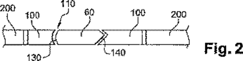
例えば、図1と2に示した仏国特許出願公開第9906729号明細書は、ミニUICCカード60または「プラグ3G」(第三世代)を受け入れる形状のUICCプラグインアダプタ/小型カード(ミニUICC)を備えている。アダプタ100はISOフォーマットのカード本体200の中の事前打ち抜き部20によって画成され、ついでストラップ22、24と26を破断することによってこの本体200から手で取り外される。
For example, French Patent Application No. 9906729 shown in FIGS. 1 and 2 describes a UICC plug-in adapter / small card (mini UICC) configured to accept a
必要に応じて、変形例によれば、アダプタはとりわけ射出成形によってフォーマットに直接製造することができる。 If necessary, according to a variant, the adapter can be manufactured directly into the format, in particular by injection molding.
つぎにミニUICCカードは、プラグインまたはISOフォーマットで使用するためにアダプタの内部に固定される。該カードはさらに、ミニUICCカードを取り外し自在に取り付けることができる相補的形状110のアダプタ内に固定されることを可能にする適合した形状130、140で製造される。
The mini UICC card is then secured inside the adapter for use in plug-in or ISO format. The card is further manufactured with a
発明者らは、アダプタ専用の区域の内部から、すなわちアダプタ内のUICCカードの最終的場所から直接ミニUICCを取り外すための試みも実施した。 The inventors have also attempted to remove the mini UICC directly from within the area dedicated to the adapter, i.e. from the final location of the UICC card in the adapter.
これらの試みは、アダプタ内に入れ直す面で技術的に十分な解決に至らなかった。 These attempts have not resulted in a technically sufficient solution in terms of reinsertion into the adapter.
他に考えられるUICCミニカードまたはアダプタのさまざまな製造方法には、
・押し抜きによって直接あるいは事前打ち抜きの後にISOカードからUICCミニカードを取り外す、
・最終フォーマットに直接分離成型、
・プラスチック板の機械的打ち抜きによる複数個のミニUICCカード体または複数個のアダプタの多重取り外し、
を実施するものがある。
Other possible methods for manufacturing UICC minicards or adapters include:
-Remove the UICC mini card from the ISO card directly by punching or after pre-punching.
・ Separate molding directly into the final format,
・ Multiple removal of multiple mini UICC card bodies or multiple adapters by mechanical punching of plastic plates,
There is something to implement.
最後に、エンドユーザーへの加入者識別カードの提供には機密情報の通信が伴う(非制限的な例として、PINコード番号およびPUK解除コード)。このために、これらの付属情報を紙に印刷したり、ISOフォーマットのカード本体上にこれらの情報を配置してからそれらを配布することが知られている。また、ISOフォーマットの(チップのない)プラスチックカードの分離自在な部分にこれらの情報を配置することも知られている。
SIMカード、アダプタと付属情報の提供のために実施される方法は、特殊な道具あるいは複数の操作を必要とし、結局は高くつくという欠点がある。 The methods implemented for providing SIM cards, adapters and attached information have the disadvantage that they require special tools or multiple operations and are ultimately expensive.
本発明は上記の問題を解決しようとするものである。 The present invention seeks to solve the above problems.
本発明の主たる目的は、アダプタとミニUICCまたは必要な場合には機密情報を最小のコストで提供することを可能にする製造方法の構想である。 The main object of the present invention is the concept of a manufacturing method that makes it possible to provide adapters and mini UICCs or, if necessary, confidential information at a minimum cost.
容易で最小コストでの工業化を可能にするために、先述の実現可能性の問題を回避しながら、アダプタとミニUICCの製造に、また必要に応じて機密情報の提供に共通の過程を最大限に使用するのが必要であることが判った。 Maximize common processes for the production of adapters and mini UICCs and, if necessary, for providing confidential information, while avoiding the feasibility problems mentioned above, in order to enable easy and minimal industrialization It was found necessary to use.
このために、本発明は、第二の標準フォーマット(UICCプラグイン)よりも小型のフォーマットのチップカード(ミニUICC)と、該チップカードに組み合わされた第二のフォーマット(UICCプラグイン)のアダプタの製造方法において、
・チップカード取り外し区域とアダプタ取り外し区域とから成るカード本体を提供し、
・媒体から少なくともチップカード(ミニUICC)を取り外す、
過程から成ることを特徴とする方法を対象とする。
To this end, the present invention provides a chip card (mini UICC) of a smaller format than the second standard format (UICC plug-in) and an adapter of the second format (UICC plug-in) combined with the chip card. In the manufacturing method of
Provide a card body consisting of a chip card removal area and an adapter removal area,
-Remove at least the chip card (mini UICC) from the medium,
The method is characterized by comprising a process.
該方法は、アダプタ取り外し区域の輪郭の外に位置する区域からチップカードを取り外す過程を備えることを特徴とする。 The method comprises the step of removing the chip card from an area located outside the contour of the adapter removal area.
好適には、第二のフォーマット(UICCプラグイン)より大きな以前の標準フォーマット(ISO)を有する媒体を使用する。 Preferably, media having a previous standard format (ISO) larger than the second format (UICC plug-in) is used.
他の特徴によれば、
・該方法はチップカードを含む第二の標準フォーマット(UICCプラグイン)の第一の小部分の事前取り外し過程を備えている;
・チップカードを含む媒体の第二の小部分を媒体から事前に取り外す;
・アダプタを含む媒体の第三の小部分を媒体から事前に取り外す、
・前記チップカード取り外し区域、個人情報と前記アダプタ取り外し区域をそれぞれ含んでいる少なくとも三つの小部分を媒体から取り外す;
・破断線の部位で種々の取り外しを手で実施する;
・機械式打ち抜き手段で種々の取り外しを実施する;
・チップカード(ミニUICC)はISOフォーマットのチップカードで実施される作業とほぼ同じ少なくとも一回の差し込み作業を実施するように媒体上に位置づけられる;
・種々の事前打ち抜きまたは破断線部は、媒体のプラスチック射出操作の際に射出型の中で直接実現される。
According to other features
The method comprises a pre-removal process of the first small part of the second standard format (UICC plug-in) containing the chip card;
Pre-removing the second small piece of media containing the chip card from the media;
Remove in advance the third small part of the media including the adapter from the media,
Removing at least three sub-portions each containing said chip card removal area, personal information and said adapter removal area;
・ Perform various removals manually at the break line;
-Perform various removals with mechanical punching means;
A chip card (mini UICC) is positioned on the medium to perform at least one insertion operation that is similar to that performed with an ISO format chip card;
-Various pre-punched or broken lines are realized directly in the injection mold during the plastic injection operation of the media.
本発明は、第二の標準フォーマット(UICCプラグイン)よりも小型のフォーマットのチップカード(ミニUICC)の取り外し区域と、第二のフォーマット(UICCプラグイン)のチップカードのアダプタ取り外し区域を含むチップカード媒体も対象とする。 The present invention relates to a chip including a removal area of a chip card (mini UICC) of a smaller format than the second standard format (UICC plug-in) and an adapter removal area of a chip card of the second format (UICC plug-in). Card media are also targeted.
媒体は、チップカード取り外し区域がアダプタ取り外し区域の輪郭の外に位置することを特徴とする。 The medium is characterized in that the chip card removal area is located outside the contour of the adapter removal area.
好適には、媒体は第二のフォーマット(UICCプラグイン)より大きな以前の標準フォーマット(ISO)を有する。 Preferably, the media has a previous standard format (ISO) that is larger than the second format (UICC plug-in).
別の特徴によれば、媒体は、
・チップカードを含む第二の標準フォーマット(UICCプラグイン)の第一の小部分;
・チップカードを含む媒体の第二の小部分;
・アダプタを含む媒体の第三の小部分;
・情報と、分離可能な媒体の第四の小部分の上の情報を隔離する破断線部;
・前記チップカード取り外し区域、前記情報と前記アダプタをそれぞれ含む破断線部によって画成された分離可能な少なくとも三つの小部分、を備え、
・種々の取り外し区域は、手による取り外しを助ける破断線によって画成されるか具体化される;
・前記情報は、PINおよび/またはPUKコードに関する情報を含んでいる;
・チップカードの接触領域はISOカードの接触領域の規格化された場所にほぼ対応している;
・アダプタは、チップカードの接触領域がいったんその中に置かれたらISOカードの接触領域の規格化された場所にほぼ対応するように媒体の中に場所を有する。
According to another feature, the medium is
A first sub-portion of a second standard format (UICC plug-in) containing a chip card;
-A second sub-portion of the medium containing the chip card;
• a third small piece of media containing the adapter;
A break line separating the information and the information on the fourth small piece of separable media;
The chip card removal area, comprising at least three separable portions defined by break line portions each containing the information and the adapter;
The various removal areas are defined or embodied by break lines that aid in manual removal;
The information includes information about the PIN and / or PUK code;
The contact area of the chip card roughly corresponds to the standardized location of the contact area of the ISO card;
The adapter has a place in the media so that once the contact area of the chip card is placed in it, it roughly corresponds to the normalized location of the contact area of the ISO card.
本発明のその他の特徴と利点は、付属の図面を参照して、非制限的な例としてあげられた下記の説明を読むことによって明らかになるものである。
図1は、すでに述べたように、アダプタを含む、現行のISO標準フォーマットのミニUICCカードの上面の模式図である。
図2は、A−Aに沿った図1の断面図である。
図3は、本発明によるアダプタとミニUICCカードのISOフォーマットの媒体の上面図である。
図4は、ミニUICCカードと「UICCプラグインカード」を画成する二重事前打ち抜きを備えた図3の図である。
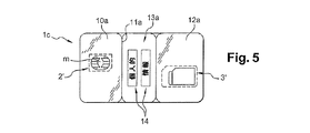
図5、6、7は、ISOフォーマットのカード内に事前打ち抜き小部分を備えた図3の図である。
Other features and advantages of the present invention will become apparent upon reading the following description, given by way of non-limiting example, with reference to the accompanying drawings.
FIG. 1 is a schematic top view of an existing ISO standard format mini UICC card including an adapter, as described above.
2 is a cross-sectional view of FIG. 1 along AA.
FIG. 3 is a top view of the ISO format medium of the adapter and mini UICC card according to the present invention.
4 is a diagram of FIG. 3 with double pre-punching defining a mini UICC card and a “UICC plug-in card”.
5, 6 and 7 are views of FIG. 3 with a pre-punched small portion in an ISO format card.
該方法によれば、第二の標準フォーマット(UICCプラグイン)よりも小型のフォーマットのチップカード(ミニUICC)と、チップカードに組み合わされた第二のフォーマット(UICCプラグイン)のアダプタは同じ媒体から取り外される。 According to this method, the chip card (mini UICC) of a smaller format than the second standard format (UICC plug-in) and the adapter of the second format (UICC plug-in) combined with the chip card are the same medium. Removed from.
図3において、既存の、実証されたチップカード生産手段を使用するように、好適にはISOフォーマットの媒体(1a)を使用する。一般的に、ミニUICC小型カードと第二のフォーマットのフォーマットより大きい以前の標準フォーマットを有する媒体を使用する。 In FIG. 3, the ISO format medium (1a) is preferably used to use the existing and proven chip card production means. In general, a medium having an earlier standard format that is larger than the format of the mini UICC small card and the second format is used.
しかしながら、アダプタとUICCミニカードの取り外し専用の少なくとも二つの区域が提供されている限り、他のフォーマットを使用してもよい。実際、本発明によれば、アダプタとUICCミニカードは、二つの異なる媒体の上にミニUICCとアダプタが作製された先行技術とは反対に、カード本体の二つの別個の区域から取り外される。 However, other formats may be used as long as at least two areas dedicated to adapter and UICC minicard removal are provided. In fact, according to the present invention, the adapter and UICC minicard are removed from two separate areas of the card body as opposed to the prior art where the mini UICC and adapter were made on two different media.
より詳細には、チップカード2は、(事前打ち抜きスリット3’を含む)アダプタ3の取り外し区域を画成する輪郭の外に位置する区域から取り外される。
More particularly, the
媒体3は、ABS、PVC、PET、などのプラスチック材料製のカード本体であり、射出または積層を始めとするチップカード分野で周知のさまざまな仕方で得ることができる。該媒体はモジュール(m)を受け入れるくぼみを備えている。モジュールは、集積回路チップに接続され、誘電フィルム上に置かれた接触領域を既知の仕方で備えている。
The
変形例において、カード本体は、アダプタ3の所定の形状、すなわちミニUICCの受け入れ空間(受け入れ用くり抜き4)および/または、例えば、図2の形状(110)のように凹形の適合した形状、ならびにその中にモジュール(m)を受け入れるためのくぼみが位置づけられたUICCミニカードの事前打ち抜き部2’を備えて、射出によって直接得られる。必要に応じて、弾性取り付け手段すなわちミニUICCの受け入れ空間の縁の上の弾性ブレード5が備えられる。
In a variant, the card body has a predetermined shape of the
例においては、誤操作防止装置6に隣接する横断縁がそれにあたる。
In the example, the transverse edge adjacent to the erroneous
このブレードは、アダプタのカード本体の第二のくり抜き6によって実現される。射出型は、そのために、このくり抜きを実現するのに適した可動コアまたはポンチを備えている。 This blade is realized by a second cut-out 6 in the card body of the adapter. The injection mold is therefore provided with a movable core or punch suitable for realizing this cut-out.
かかるくり抜きは、加工によって実現することもできる。 Such hollowing can also be realized by processing.
差し込みの後、また必要に応じて電気的個性化、テスト、図形印刷などの後、つづいてミニUICCおよび/またはアダプタの取り外しに着手することができる。 After plugging in and after electrical personalization, testing, graphic printing, etc., if necessary, the mini UICC and / or adapter can be removed.
このようにして、二つの本体、すなわち、ミニUICCとアダプタの実現のために、射出、印刷、図形個人化および唯一の製造ラインなどの共通の過程が利用できる。 In this way, common processes such as injection, printing, figure personalization and a single production line can be used for the realization of the two bodies, namely the mini UICC and the adapter.
取り外しは、ミニUICCおよび/またはアダプタの打ち抜き、押し抜きなどによって、いろいろなときに実施できる。つぎに二つの要素は、必要に応じてカードに関する情報を備えた媒体とともに、一緒に包装される。カード、アダプタと情報は例えば、一緒に袋詰めにしたり、接着剤で紙の上に固定することができる。 Removal can be performed at various times by punching, punching, etc. of the mini UICC and / or adapter. The two elements are then packaged together with media with information about the card as needed. Cards, adapters and information can be packaged together or fixed on paper with an adhesive, for example.
好適には、ペアリング、包装の便宜、広告(ISOカード本体上のロゴ)を理由として、エンドユーザーによって手で取り外しが実施される;このため、指でわざと押しつけて、あるいは他の簡単な手段でそれぞれの要素を取り外せるように、アダプタの周囲とミニUICCの周囲に材料薄肉部が備えられている。これらの薄肉部または事前打ち抜きは仏国特許発明第2778002号明細書に記載のごとく、例えば、射出の際に、あるいは後から機械的事前打ち抜きによって実現される。 Preferably, the removal is performed manually by the end user for pairing, packaging convenience, advertising (logo on ISO card body); for this purpose, either by hand or by other simple means A thin material portion is provided around the adapter and around the mini UICC so that each element can be removed. These thin portions or pre-punching are realized, for example, at the time of injection or later by mechanical pre-punching as described in the specification of French Patent No. 2777802.
好適には、チップカードの製造に固有の道具および機械を使用できるように媒体はISOフォーマットである。 Preferably, the media is in ISO format so that tools and machines specific to chip card manufacture can be used.
したがって、例えば、得られた製品において、ミニUICC専用の区域は、モジュール(m)のくぼみを備えており、その場所はISOに合致したチップカードのモジュールの場所にほぼ対応する。したがって、差し込みは、モジュール差し込み機を用いて、調節や調整はほとんどなしに、可能になる。 Thus, for example, in the resulting product, the area dedicated to the mini UICC is provided with an indentation of module (m), the location approximately corresponding to the location of the chip card module that conforms to ISO. Insertion is therefore possible with little adjustment or adjustment using a module inserter.
カード本体内に別のくぼみの場所も可能であるが、機械の調整が必要になるだろう。 Other indentations are possible in the card body, but machine adjustments will be required.
取り外しの前に得られた製品は、ISOフォーマットのチップカードとして使用可能であるが、それが目的ではなく、またアダプタに関する事前打ち抜きの存在を考慮するとISOの基準を満たさない。 The product obtained prior to removal can be used as an ISO format chip card, but it is not the purpose and does not meet ISO standards in view of the presence of pre-punching for adapters.
アダプタ専用の区域は、カード本体のさまざまな場所に(ミニUICC取り外し区域の外に)配置することができる。しかしながら、そこに位置づけられた小型カードの接触領域が(カードの面内で180度回転した後、および/またはカードを裏返した後でも)ISOチップカードの接触領域の規格化された場所とほぼ一致するような場所が望ましい。 The area dedicated to the adapter can be located at various locations on the card body (outside of the mini UICC removal area). However, the contact area of the small card located there is almost identical to the standardized location of the contact area of the ISO chip card (even after rotating 180 degrees in the plane of the card and / or after turning the card over) Such a place is desirable.
したがって、携帯電話に使用するためにミニUICCを取り外し、その後ミニUICCを、取り外していないアダプタ内に置き直して、ISOフォーマットのチップカードの外形を得ることが可能である。 Therefore, it is possible to remove the mini UICC for use in a mobile phone, and then place the mini UICC in a non-removed adapter to obtain the ISO format chip card outline.
本発明によれば、ミニUICCおよび/またはアダプタを備えた媒体の第一の小部分はあらかじめ媒体から取り外される。 According to the present invention, the first small portion of the media with the mini UICC and / or adapter is previously removed from the media.
図4に示した特に注目すべき変形例において、該部分はUICCプラグインの輪郭に対応している。カード1bは、UICCプラグインの取り外し専用区域8を備えている。この区域は、その他の取り外し区域と同様に設計し取り外すことができる。
In the particularly notable variant shown in FIG. 4, this part corresponds to the contour of the UICC plug-in. The card 1b is provided with a UICC plug-in
好適には、UICCプラグインカードの輪郭9に対応し、手でそれを取り外すのを容易にする薄肉部もしくは部分的事前打ち抜きまたは(連結ストラップの有無を問わず)破断線部が備えられる。
Preferably, a thin-walled or partially pre-punched or broken line (with or without connecting straps) is provided that corresponds to the UICC plug-in
実施例において、ISOフォーマットの媒体は、ISOフォーマットのエンドユーザーによる使用のためのものではない。この媒体は、ISO規格の曲げねじり試験に耐えられないだろう。 In an embodiment, ISO format media is not intended for use by ISO format end users. This media will not withstand the ISO standard bending torsion test.
ユーザーが、一方がUICCプラグインカード用の、他方がミニUICCカード用の二台の電話を有する場合、ミニUICCとアダプタを分離するだけで両電話を交互に使用することができるだろう。 If the user has two phones, one for the UICC plug-in card and the other for the mini UICC card, it would be possible to use both phones alternately by simply separating the mini UICC and adapter.
UICCプラグインフォーマットで使用するときは、ミニUICCを、取り外したアダプタ内に位置づけるだけでよい。 When used in the UICC plug-in format, the mini UICC need only be positioned within the removed adapter.
本発明によれば、小型カードを含む少なくとも一つの媒体の第二の小部分10aおよび/またはアダプタを含む少なくとも一つの媒体の第三の小部分12aをあらかじめ媒体から取り外すことができる。好適には、手で取り外す場合、先にミニUICCを取り外してから小部分10aを分離する。
According to the present invention, the second
結果として得られる製品は図5、6、7に示した。該製品に含まれる小部分10a、10b、10cと12a、12b、12cはそれぞれミニUICC用とアダプタ用のものであり、実施例では、角をほぼ丸くしたとりわけ長方形などのさまざまな形状をとることができる。これらの小部分は先に述べたごとく(とりわけ射出で)設計し、取り外しを助ける破断線部、それぞれ11a、11b、11cによって画成することができる。
The resulting product is shown in FIGS. The
例えば、カード本体(1aから1e)は、長さが85mm、幅が54mm、厚みが760μmである。 For example, the card body (1a to 1e) has a length of 85 mm, a width of 54 mm, and a thickness of 760 μm.
本体1c、1dは、三つの横断方向の事前打ち抜きに個人的情報(PIN識別コード)、または、例えば、加入に関する情報(PUK解除コード)などとすることができる情報14を受け入れるための別個の第五の小部分13a、13bを備えている。これらの情報は、アダプタを含む小部分と同一の小部分12cの上とすることができる。
The
小部分は、容易に操作するのに適した、あるいは、例えば、財布の中に保管するのに適した形状、とりわけ長方形の薄くて細長い形を有する。 The small part has a shape suitable for easy manipulation or, for example, suitable for storage in a purse, in particular a rectangular thin and elongated shape.
保管するための小部分は、好適には角が丸い破断線部によって画成される。 The small part for storage is preferably defined by a broken line with rounded corners.
したがって、該方法は、三つのもの(カード、アダプタ、情報)の実現に関わる印刷と図形個人化(番号、バーコードなどの印刷)などの共通過程を使用することで大幅に単純化され、差し込み機(モジュールをカード本体のくぼみに挿入)だけでなく、ISOフォーマットが過去のものになろうとしているとしても、ISOフォーマットのカードの試験機、包装機、操作機も使用される。 Therefore, the method is greatly simplified by using common processes such as printing and graphic personalization (printing numbers, barcodes, etc.) related to the realization of three things (card, adapter, information) In addition to the machine (inserting the module into the recess of the card body), even if the ISO format is going to be a thing of the past, ISO format card testing machines, packaging machines, and operating machines are also used.
カードとアダプタの取り外し後に残った材料は、とりわけ加入者関連機密情報の担持に、あるいは財布に入れることができる操作が容易な保存媒体を意図して有益に用いることができる。 The material remaining after removal of the card and adapter can be beneficially used, inter alia, for carrying sensitive subscriber-related information or for easy-to-operate storage media that can be placed in a wallet.
最後に、ミニUICCチップカードとペアリングするための情報は、共通媒体3の上に該情報を印刷することで必然的にペアリングされる。包装、ユニットを構成する種々の小部分の管理、顧客への提示がそれによって容易になる。
Finally, information for pairing with the mini UICC chip card is necessarily paired by printing the information on the
2 チップカード
3 アダプタ
4 受け入れ用くり抜き
5 弾性ブレード
2
Claims (20)
・チップカード取り外し区域とアダプタ取り外し区域とから成るカード本体を提供し、
・媒体から少なくともチップカード(ミニUICC)を取り外し、
・アダプタ取り外し区域の輪郭の外に位置する区域からチップカード(2)を取り外す、
過程から成り、
ここで用いるアダプタが、チップカードの接触領域がいったんその中に置かれたらISOカードの接触領域の規格化された場所にほぼ対応するように媒体の中に場所を有するものであることを特徴とする方法。In a method of manufacturing a chip card (mini UICC) of a smaller format than the second standard format (UICC plug-in) and an adapter of the second format (UICC plug-in) combined with the chip card,
Provide a card body consisting of a chip card removal area and an adapter removal area,
- at least remove the chip card (mini-UICC) from the medium,
Adapter removed from areas located outside the contour of the removal area the chip card (2),
Consisting of processes ,
The adapter used here has a place in the medium so that the contact area of the chip card once corresponds to the standardized place of the contact area of the ISO card. how to.
チップカード取り外し区域が、アダプタ(3)の取り外し区域の輪郭の外に位置し、アダプタが、チップカードの接触領域がいったんその中に置かれたらISOカードの接触領域の規格化された場所にほぼ対応するように媒体の中に場所を有することを特徴とするチップカード媒体。Includes a removal area for a chip card (mini UICC 2) of a smaller format than the second standard format (UICC plug-in 9) and a removal area for a chip card adapter (3) of the second format (UICC plug-in) In chip card media,
The chip card removal area is located outside the outline of the removal area of the adapter (3), and the adapter is approximately at the standardized location of the ISO card contact area once the chip card contact area is placed therein. chip card medium characterized by have a place in the medium to correspond to.
Applications Claiming Priority (3)
| Application Number | Priority Date | Filing Date | Title |
|---|---|---|---|
| FR0451478 | 2004-07-08 | ||
| FR0451478A FR2872946B1 (en) | 2004-07-08 | 2004-07-08 | METHOD FOR MANUFACTURING A MINI UICC CHIP CARD HOLDER WITH UICC PLUG-IN ADAPTER AND A SUPPORT OBTAINED |
| PCT/EP2005/052544 WO2006010664A2 (en) | 2004-07-08 | 2005-06-02 | Method of producing a mini uicc smart card support with an associated plug-in uicc adapter, and support thus obtained |
Publications (2)
| Publication Number | Publication Date |
|---|---|
| JP2008506171A JP2008506171A (en) | 2008-02-28 |
| JP4853733B2 true JP4853733B2 (en) | 2012-01-11 |
Family
ID=34946777
Family Applications (1)
| Application Number | Title | Priority Date | Filing Date |
|---|---|---|---|
| JP2007519756A Expired - Fee Related JP4853733B2 (en) | 2004-07-08 | 2005-06-02 | Method of manufacturing mini UICC chip card medium with combined UICC plug-in adapter and resulting medium |
Country Status (8)
| Country | Link |
|---|---|
| US (1) | US7837122B2 (en) |
| EP (1) | EP1769429B1 (en) |
| JP (1) | JP4853733B2 (en) |
| CN (1) | CN100573571C (en) |
| DE (1) | DE602005003476T2 (en) |
| ES (1) | ES2297720T3 (en) |
| FR (1) | FR2872946B1 (en) |
| WO (1) | WO2006010664A2 (en) |
Families Citing this family (35)
| Publication number | Priority date | Publication date | Assignee | Title |
|---|---|---|---|---|
| JP4943331B2 (en) * | 2004-08-10 | 2012-05-30 | ジエマルト・エス・アー | Gradual unplug multiple card body |
| FR2882175B1 (en) * | 2005-02-11 | 2007-06-22 | Oberthur Card Syst Sa | CARD HOLDER, METHOD OF USE, AND ADAPTER CARD ASSEMBLY |
| FR2885718B1 (en) * | 2005-05-11 | 2007-09-21 | Gemplus Sa | ADHESIVE FORMAT ADAPTER FOR MEMORY DEVICE AND METHOD OF MANUFACTURE |
| KR100798685B1 (en) * | 2007-05-31 | 2008-01-28 | 주식회사 제이디씨텍 | A process of manufacture for liquid crystal display smart card |
| DE102008012082A1 (en) * | 2008-02-29 | 2009-09-24 | T-Mobile International Ag | Memory card with integrated SIM |
| DE102008019571A1 (en) | 2008-04-18 | 2009-10-22 | Giesecke & Devrient Gmbh | Chip card and method for its production |
| DE102008021519B3 (en) * | 2008-04-30 | 2009-10-01 | Giesecke & Devrient Gmbh | Security element with IC card |
| CN101953187B (en) * | 2008-07-10 | 2014-08-27 | Sk普兰尼特有限公司 | Personalized service system based on smart car and method thereof, and smart card applied to the same |
| US7986158B2 (en) * | 2008-08-21 | 2011-07-26 | OFID Microdevices, Inc. | Methods, apparatuses, and products for a secure circuit |
| FR2936072B1 (en) * | 2008-09-15 | 2012-12-07 | Oberthur Technologies | PORTABLE ELECTRONIC DEVICE WITH USB CONNECTOR. |
| DE102008063706A1 (en) * | 2008-12-19 | 2010-07-01 | Austria Card Gmbh | Device for contactless personalization of subscriber identity module card, has cutting lines guided to contact surfaces of chips of subscriber identity module card by bars lying between cutting lines |
| EP2309430B1 (en) | 2009-09-30 | 2015-01-07 | Cairon Group GmbH | Adapter for a mini UICC card |
| KR101275983B1 (en) * | 2010-09-01 | 2013-06-14 | 현대카드 주식회사 | A metal payment card and make method thereof |
| US8555067B2 (en) | 2010-10-28 | 2013-10-08 | Apple Inc. | Methods and apparatus for delivering electronic identification components over a wireless network |
| US8446728B1 (en) * | 2011-01-03 | 2013-05-21 | Wade S. McDonald | Flash memory card carrier |
| DE202011001921U1 (en) * | 2011-01-25 | 2011-04-28 | Cairon Group Gmbh | Adapter for a mini-UICC card |
| US8620271B2 (en) * | 2011-04-29 | 2013-12-31 | Apple Inc. | Compact form factor integrated circuit card and methods |
| US8950681B2 (en) | 2011-11-07 | 2015-02-10 | Blackberry Limited | Universal integrated circuit card apparatus and related methods |
| USD691610S1 (en) * | 2011-11-07 | 2013-10-15 | Blackberry Limited | Device smart card |
| US8649820B2 (en) | 2011-11-07 | 2014-02-11 | Blackberry Limited | Universal integrated circuit card apparatus and related methods |
| USD702692S1 (en) * | 2011-11-23 | 2014-04-15 | Digital Hard Copy | Card for holding a digital storage medium |
| USD702693S1 (en) * | 2011-11-23 | 2014-04-15 | Digital Hard Copy | Digital storage medium card |
| EP2608115A1 (en) * | 2011-12-22 | 2013-06-26 | Gemalto SA | Multi-format chip card |
| USD703208S1 (en) * | 2012-04-13 | 2014-04-22 | Blackberry Limited | UICC apparatus |
| US8936199B2 (en) | 2012-04-13 | 2015-01-20 | Blackberry Limited | UICC apparatus and related methods |
| USD701864S1 (en) * | 2012-04-23 | 2014-04-01 | Blackberry Limited | UICC apparatus |
| NL1039642C2 (en) * | 2012-05-18 | 2013-11-20 | Willemsen | CHIP CARD DEVICE AND METHOD FOR MANUFACTURING THEM. |
| EP2674897B1 (en) * | 2012-06-15 | 2019-03-06 | IDEMIA France | A data carrier having a microcircuit card and a method for making such a card |
| USD707682S1 (en) * | 2012-12-05 | 2014-06-24 | Logomotion, S.R.O. | Memory card |
| FR3015087B1 (en) | 2013-12-13 | 2017-05-12 | Plastifrance | SUPPORT OF MULTIPLE FORMAT CARDS AND REVERSIBLE POSITIONING STABLE. |
| US9877191B2 (en) * | 2014-10-15 | 2018-01-23 | Tracfone Wireless, Inc. | Device having a SIM card combined with a wireless service card and method of use thereof |
| US9883374B2 (en) * | 2015-04-21 | 2018-01-30 | Tracfone Wireless, Inc. | System and process for having wireless service value included in a SIM card |
| USD855617S1 (en) * | 2017-01-17 | 2019-08-06 | David Williams | Smart card |
| US10984304B2 (en) | 2017-02-02 | 2021-04-20 | Jonny B. Vu | Methods for placing an EMV chip onto a metal card |
| USD956760S1 (en) * | 2018-07-30 | 2022-07-05 | Lion Credit Card Inc. | Multi EMV chip card |
Family Cites Families (20)
| Publication number | Priority date | Publication date | Assignee | Title |
|---|---|---|---|---|
| DE3420051A1 (en) * | 1984-05-29 | 1985-12-05 | GAO Gesellschaft für Automation und Organisation mbH, 8000 München | DATA CARRIER WITH IC COMPONENT AND METHOD FOR PRODUCING SUCH A DATA CARRIER |
| JPS62214998A (en) * | 1986-03-17 | 1987-09-21 | 三菱電機株式会社 | Thin-type semiconductor card |
| DE4007221A1 (en) * | 1990-03-07 | 1991-09-12 | Gao Ges Automation Org | TEST HEAD FOR CONTACT AREAS OF VALUE CARDS WITH STORED SEMICONDUCTOR CHIP |
| US5581065A (en) * | 1993-08-02 | 1996-12-03 | Dai Nippon Printing Co., Ltd. | Sheet-framed IC carrier, method for producing the same, and IC carrier case |
| DE19606789C2 (en) * | 1996-02-23 | 1998-07-09 | Orga Kartensysteme Gmbh | Plastic card with a mini chip card that can be removed from it |
| DE19703122C1 (en) * | 1997-01-29 | 1998-05-20 | Orga Kartensysteme Gmbh | Process for the production of data carriers |
| KR100255108B1 (en) * | 1997-06-18 | 2000-05-01 | Samsung Electronics Co Ltd | Chip card |
| FR2773900B1 (en) * | 1998-01-22 | 2000-02-18 | Gemplus Card Int | CARD WITH INTEGRATED CONTACT CIRCUIT (S), COMPRISING A DETACHABLE MINICARD |
| FR2778002B1 (en) * | 1998-04-22 | 2000-06-30 | Gemplus Card Int | METHOD FOR MANUFACTURING AN INTEGRATED CONTACT CIRCUIT CARD AND A CARD OBTAINED ACCORDING TO THIS PROCESS |
| FR2783948B1 (en) * | 1998-09-24 | 2000-11-10 | Gemplus Card Int | LARGE FORMAT CHIP CARD COMPRISING A DETACHABLE MINI-CARD AND MANUFACTURING METHOD |
| DE29819389U1 (en) * | 1998-10-30 | 1999-01-28 | Orga Kartensysteme Gmbh | Smart card |
| DE19901965A1 (en) * | 1999-01-19 | 2000-07-20 | Giesecke & Devrient Gmbh | Portable data carrier for mobile phone systems, with detachable mini chip card having perforated break line for further miniaturization of mini chip card |
| DE19906569A1 (en) * | 1999-02-17 | 2000-09-07 | Giesecke & Devrient Gmbh | Portable data carrier with breakout mini chip card |
| FR2793331B1 (en) * | 1999-05-06 | 2001-08-10 | Oberthur Card Systems Sas | METHOD FOR MANUFACTURING A MICROCIRCUIT CARD |
| FR2794264B1 (en) * | 1999-05-27 | 2001-11-02 | Gemplus Card Int | ADAPTER FOR PORTABLE ELECTRONIC DEVICE WITH INTEGRATED CIRCUIT, OF THE CHIP CARD TYPE, OF A REDUCED FORMAT IN RELATION TO THE STANDARD FORMAT OF A MINI-CARD |
| US6653565B2 (en) * | 2001-04-27 | 2003-11-25 | Matsushita Electric Industrial Co., Ltd. | IC card with plated frame and method for manufacturing the same |
| EP1508122B1 (en) * | 2002-05-24 | 2006-07-05 | NTT DoCoMo, Inc. | Chip card of reduced size with backward compatibility |
| JP4402420B2 (en) * | 2003-08-06 | 2010-01-20 | 大日本印刷株式会社 | UIM with plate-shaped frame and manufacturing method thereof |
| US7597250B2 (en) * | 2003-11-17 | 2009-10-06 | Dpd Patent Trust Ltd. | RFID reader with multiple interfaces |
| FR2885718B1 (en) * | 2005-05-11 | 2007-09-21 | Gemplus Sa | ADHESIVE FORMAT ADAPTER FOR MEMORY DEVICE AND METHOD OF MANUFACTURE |
-
2004
- 2004-07-08 FR FR0451478A patent/FR2872946B1/en not_active Expired - Fee Related
-
2005
- 2005-06-02 ES ES05749237T patent/ES2297720T3/en active Active
- 2005-06-02 CN CNB2005800302227A patent/CN100573571C/en not_active Expired - Fee Related
- 2005-06-02 EP EP05749237A patent/EP1769429B1/en not_active Not-in-force
- 2005-06-02 WO PCT/EP2005/052544 patent/WO2006010664A2/en active Application Filing
- 2005-06-02 JP JP2007519756A patent/JP4853733B2/en not_active Expired - Fee Related
- 2005-06-02 DE DE602005003476T patent/DE602005003476T2/en active Active
- 2005-06-02 US US11/631,813 patent/US7837122B2/en not_active Expired - Fee Related
Also Published As
| Publication number | Publication date |
|---|---|
| US20080251587A1 (en) | 2008-10-16 |
| EP1769429A2 (en) | 2007-04-04 |
| JP2008506171A (en) | 2008-02-28 |
| ES2297720T3 (en) | 2008-05-01 |
| CN100573571C (en) | 2009-12-23 |
| US7837122B2 (en) | 2010-11-23 |
| WO2006010664A2 (en) | 2006-02-02 |
| FR2872946A1 (en) | 2006-01-13 |
| CN101014970A (en) | 2007-08-08 |
| EP1769429B1 (en) | 2007-11-21 |
| WO2006010664A3 (en) | 2006-06-01 |
| DE602005003476T2 (en) | 2008-09-25 |
| DE602005003476D1 (en) | 2008-01-03 |
| FR2872946B1 (en) | 2006-09-22 |
Similar Documents
| Publication | Publication Date | Title |
|---|---|---|
| JP4853733B2 (en) | Method of manufacturing mini UICC chip card medium with combined UICC plug-in adapter and resulting medium | |
| US9195930B2 (en) | Method for manufacturing a card based on a substrate | |
| US7770800B2 (en) | SIM card packaging | |
| US7731095B2 (en) | Ternary SIM card delivery | |
| JP4943331B2 (en) | Gradual unplug multiple card body | |
| US20130175346A1 (en) | Sim card and method for producing same | |
| EP2232415B1 (en) | A method for manufacturing a plurality of plug-in cards from a card body. | |
| JP5002455B2 (en) | Multi-standard card | |
| US20080083108A1 (en) | Method Of Preparing A Smart Card For Use | |
| TWI406453B (en) | Card with detachable subscriber identity module cards and method of forming same | |
| MX2009001973A (en) | Method for producing a data storage medium in the form of a card. | |
| JP2006504207A (en) | Data support with several electronic modules mounted on the same surface | |
| US20170270397A1 (en) | Data Carrier Comprising a Partial Piece | |
| JP4641159B2 (en) | IC card for UIM | |
| EP2851849B1 (en) | A card body, a manufacturing method for an ic card, and the ic card | |
| WO2011063721A1 (en) | Card with a plurality of subscriber identity module cards | |
| TWI379240B (en) | Ternary sim card delivery and method of preparing a smart card for use |
Legal Events
| Date | Code | Title | Description |
|---|---|---|---|
| A621 | Written request for application examination |
Free format text: JAPANESE INTERMEDIATE CODE: A621 Effective date: 20080530 |
|
| A977 | Report on retrieval |
Free format text: JAPANESE INTERMEDIATE CODE: A971007 Effective date: 20110411 |
|
| A131 | Notification of reasons for refusal |
Free format text: JAPANESE INTERMEDIATE CODE: A131 Effective date: 20110419 |
|
| A521 | Written amendment |
Free format text: JAPANESE INTERMEDIATE CODE: A523 Effective date: 20110714 |
|
| TRDD | Decision of grant or rejection written | ||
| A01 | Written decision to grant a patent or to grant a registration (utility model) |
Free format text: JAPANESE INTERMEDIATE CODE: A01 Effective date: 20110816 |
|
| A01 | Written decision to grant a patent or to grant a registration (utility model) |
Free format text: JAPANESE INTERMEDIATE CODE: A01 |
|
| A711 | Notification of change in applicant |
Free format text: JAPANESE INTERMEDIATE CODE: A712 Effective date: 20111006 |
|
| A61 | First payment of annual fees (during grant procedure) |
Free format text: JAPANESE INTERMEDIATE CODE: A61 Effective date: 20111012 |
|
| A521 | Written amendment |
Free format text: JAPANESE INTERMEDIATE CODE: A821 Effective date: 20111007 |
|
| FPAY | Renewal fee payment (event date is renewal date of database) |
Free format text: PAYMENT UNTIL: 20141104 Year of fee payment: 3 |
|
| R150 | Certificate of patent or registration of utility model |
Ref document number: 4853733 Country of ref document: JP Free format text: JAPANESE INTERMEDIATE CODE: R150 Free format text: JAPANESE INTERMEDIATE CODE: R150 |
|
| R250 | Receipt of annual fees |
Free format text: JAPANESE INTERMEDIATE CODE: R250 |
|
| R250 | Receipt of annual fees |
Free format text: JAPANESE INTERMEDIATE CODE: R250 |
|
| R250 | Receipt of annual fees |
Free format text: JAPANESE INTERMEDIATE CODE: R250 |
|
| R250 | Receipt of annual fees |
Free format text: JAPANESE INTERMEDIATE CODE: R250 |
|
| R250 | Receipt of annual fees |
Free format text: JAPANESE INTERMEDIATE CODE: R250 |
|
| R250 | Receipt of annual fees |
Free format text: JAPANESE INTERMEDIATE CODE: R250 |
|
| LAPS | Cancellation because of no payment of annual fees |