JP4852194B2 - System and method for coordinating message flows in a digital data network - Google Patents
System and method for coordinating message flows in a digital data network Download PDFInfo
- Publication number
- JP4852194B2 JP4852194B2 JP2000545110A JP2000545110A JP4852194B2 JP 4852194 B2 JP4852194 B2 JP 4852194B2 JP 2000545110 A JP2000545110 A JP 2000545110A JP 2000545110 A JP2000545110 A JP 2000545110A JP 4852194 B2 JP4852194 B2 JP 4852194B2
- Authority
- JP
- Japan
- Prior art keywords
- virtual circuit
- flow control
- buffer
- message
- circuit
- Prior art date
- Legal status (The legal status is an assumption and is not a legal conclusion. Google has not performed a legal analysis and makes no representation as to the accuracy of the status listed.)
- Expired - Lifetime
Links
Images


Classifications
-
- H—ELECTRICITY
- H04—ELECTRIC COMMUNICATION TECHNIQUE
- H04L—TRANSMISSION OF DIGITAL INFORMATION, e.g. TELEGRAPHIC COMMUNICATION
- H04L12/00—Data switching networks
- H04L12/54—Store-and-forward switching systems
- H04L12/56—Packet switching systems
- H04L12/5601—Transfer mode dependent, e.g. ATM
- H04L12/5602—Bandwidth control in ATM Networks, e.g. leaky bucket
-
- H—ELECTRICITY
- H04—ELECTRIC COMMUNICATION TECHNIQUE
- H04L—TRANSMISSION OF DIGITAL INFORMATION, e.g. TELEGRAPHIC COMMUNICATION
- H04L47/00—Traffic control in data switching networks
- H04L47/10—Flow control; Congestion control
-
- H—ELECTRICITY
- H04—ELECTRIC COMMUNICATION TECHNIQUE
- H04L—TRANSMISSION OF DIGITAL INFORMATION, e.g. TELEGRAPHIC COMMUNICATION
- H04L47/00—Traffic control in data switching networks
- H04L47/10—Flow control; Congestion control
- H04L47/16—Flow control; Congestion control in connection oriented networks, e.g. frame relay
-
- H—ELECTRICITY
- H04—ELECTRIC COMMUNICATION TECHNIQUE
- H04L—TRANSMISSION OF DIGITAL INFORMATION, e.g. TELEGRAPHIC COMMUNICATION
- H04L47/00—Traffic control in data switching networks
- H04L47/10—Flow control; Congestion control
- H04L47/26—Flow control; Congestion control using explicit feedback to the source, e.g. choke packets
- H04L47/263—Rate modification at the source after receiving feedback
-
- H—ELECTRICITY
- H04—ELECTRIC COMMUNICATION TECHNIQUE
- H04L—TRANSMISSION OF DIGITAL INFORMATION, e.g. TELEGRAPHIC COMMUNICATION
- H04L47/00—Traffic control in data switching networks
- H04L47/10—Flow control; Congestion control
- H04L47/30—Flow control; Congestion control in combination with information about buffer occupancy at either end or at transit nodes
-
- H—ELECTRICITY
- H04—ELECTRIC COMMUNICATION TECHNIQUE
- H04Q—SELECTING
- H04Q11/00—Selecting arrangements for multiplex systems
- H04Q11/04—Selecting arrangements for multiplex systems for time-division multiplexing
- H04Q11/0428—Integrated services digital network, i.e. systems for transmission of different types of digitised signals, e.g. speech, data, telecentral, television signals
- H04Q11/0478—Provisions for broadband connections
-
- H—ELECTRICITY
- H04—ELECTRIC COMMUNICATION TECHNIQUE
- H04L—TRANSMISSION OF DIGITAL INFORMATION, e.g. TELEGRAPHIC COMMUNICATION
- H04L12/00—Data switching networks
- H04L12/54—Store-and-forward switching systems
- H04L12/56—Packet switching systems
- H04L12/5601—Transfer mode dependent, e.g. ATM
- H04L2012/5629—Admission control
- H04L2012/5631—Resource management and allocation
- H04L2012/5632—Bandwidth allocation
- H04L2012/5635—Backpressure, e.g. for ABR
-
- H—ELECTRICITY
- H04—ELECTRIC COMMUNICATION TECHNIQUE
- H04L—TRANSMISSION OF DIGITAL INFORMATION, e.g. TELEGRAPHIC COMMUNICATION
- H04L12/00—Data switching networks
- H04L12/54—Store-and-forward switching systems
- H04L12/56—Packet switching systems
- H04L12/5601—Transfer mode dependent, e.g. ATM
- H04L2012/5638—Services, e.g. multimedia, GOS, QOS
- H04L2012/5646—Cell characteristics, e.g. loss, delay, jitter, sequence integrity
- H04L2012/5651—Priority, marking, classes
-
- H—ELECTRICITY
- H04—ELECTRIC COMMUNICATION TECHNIQUE
- H04L—TRANSMISSION OF DIGITAL INFORMATION, e.g. TELEGRAPHIC COMMUNICATION
- H04L12/00—Data switching networks
- H04L12/54—Store-and-forward switching systems
- H04L12/56—Packet switching systems
- H04L12/5601—Transfer mode dependent, e.g. ATM
- H04L2012/5678—Traffic aspects, e.g. arbitration, load balancing, smoothing, buffer management
- H04L2012/5681—Buffer or queue management
- H04L2012/5682—Threshold; Watermark
Description
【0001】
発明の分野
本発明は一般的にはデジタル通信システムの分野に関し、さらに具体的には、例えば、デジタルイメージ(画像)、オーディオおよびビデオ配信システムでのデジタルデータの通信とデジタルコンピュータシステム相互間の通信を容易化するデジタルネットワークに関する。さらに具体的には、本発明は、輻輳を防止し、データ損失を防止し、ネットワークを利用して情報を転送する複数のデバイス間で公平性を保つように、ネットワークを通る情報のフロー(流れ)を調整するフロー制御およびスケジューリング構成を目的としている。
【0002】
発明の背景
データとプログラムを含む情報を、デジタルコンピュータシステムや他のデジタルデバイス相互間で転送することを容易化するデジタルネットワークはすでに開発されている。種々タイプのネットワークは、種々の情報転送技法を使用して開発され、構築されている。周知のEthernetなどの、いくつかのネットワークでは、ネットワークに接続されたデバイスのすべてを相互接続するためにシングルワイヤが使用されている。この方法によると、施設内のネットワークの配線が単純化され、デバイスをネットワークに接続することが単純化されるが、ワイヤはメッセージの形をした情報を、一度に1つのデバイスからしか伝達できないために情報転送が全体的に低速になっている。この問題をある程度軽減するために、いくつかのEthernet設置施設では、ネットワークはいくつかのサブネットワークに分割され、各サブネットワークが別々のワイヤを有し、これらのワイヤはインタフェースで相互に接続されている。このような施設では、ワイヤはそこに接続されたデバイスのメッセージを同時に伝達できるために、同時に転送できるメッセージの数が増加している。2またはそれ以上のサブネットワーク内のワイヤが使用されるのは、あるワイヤに接続されたデバイスが別のワイヤに接続されたデバイスにメッセージを送信する必要があるときだけであるため、ワイヤに接続された他のデバイスはサブネットワークを利用できないようになっている。
【0003】
この問題をさらに軽減するために、メッシュ(網)状のスイッチングノードを通してコミュニケーション(通信)が処理されるようにしたネットワークが開発されている。コンピュータシステムと他のデバイスは種々のスイッチングノードに接続されている。スイッチングノード自体はさまざまなパターンで相互接続されているために、デバイスのペア間で複数のパス (path) が利用できるので、あるパスが輻輳しているとき、別のパスが使用できるようになっている。このような構成では、ネットワークはEthernetネットワークよりも複雑化するが、特に、スイッチングノードとデバイスを相互接続する媒体として光ファイバが使用される場合には、情報転送レートを大幅に高速化することを可能にしている。この種のネットワークには次のような問題がある。すなわち、この種のネットワークでは、スイッチングノードまたはデバイスがネットワーク内の別のスイッチングノードまたはデバイスから情報を受信するとき、「フロー制御(flow-control)」情報を送信側スイッチングノードまたはデバイスに提供するメカニズムがないことである。このようにすると、ネットワークのコストは確かに低減されるが、輻輳を引き起こす原因になり、輻輳が起こると、スイッチングノードは送信能力以上の高速レートで情報を受信することになるか、あるいはデスティネーションデバイスは情報をバッファに格納し、情報を処理できる以上の高速レートで情報を受信することになっている。
【0004】
発明の概要
本発明は、通信ネットワークにおけるメッセージ転送をスケジューリングする新規で、改良されたシステムおよび方法を提供することを目的としている。
【0005】
要約して簡単に説明すると、本発明の一実施形態によれば、少なくとも1つの通信リンクを含むネットワークによって相互接続された少なくとも2つのデバイスを含んでいるシステムが提供されている。各デバイスは、ネットワークを利用してメッセージを転送するためのネットワークインタフェースを装備している。これらデバイスの少なくとも1つは、ソースデバイス (source device) として、ネットワーク上に確立された1つまたは2つ以上の仮想回線 (virtual circuit) を利用してメッセージを送信し、他の前記デバイスの少なくとも1つは、それぞれの仮想回線のデスティネーションデバイス (destination device) として、仮想回線を利用してメッセージを受信する。デスティネーションデバイスのネットワークインタフェースは、デバイスがそのデスティネーションデバイスとなっているすべての仮想回線上で受信されたメッセージをバッファに格納するように構成されたバッファを含んでいる受信セクションと、デスティネーションフロー制御回路とを含んでいる。デスティネーションフロー制御回路は、(i) 1つの仮想回線上で受信されたメッセージによって占有されている前記バッファの部分が、選択した仮想回線フロー制御しきいレベルを超えたときは、デバイスがデスティネーションデバイスとなっている仮想回線に関連する仮想回線フロー制御メッセージを生成して通信リンク上をその仮想回線に対するソースデバイスに転送し、および(ii) メッセージによって占有されている前記バッファの部分が、選択したリンクフロー制御しきいレベルを超えたときは、リンクフロー制御メッセージを生成して前記通信リンク上を送信するようになっている。ソースデバイスのネットワークインタフェースは、それがソースデバイスとなっている1つまたは2つ以上の仮想回線上にメッセージを送信するように構成された送信セクションと、ソースフロー制御回路とを含んでいる。ソースフロー制御回路は、(i) 仮想回線に関連する仮想回線フロー制御メッセージが前記ソースデバイスによって受信されると、それに応答して、送信セクションが仮想回線上にメッセージを送信することを禁止し、(ii) そこに接続された通信リンク上でリンクフロー制御メッセージがソースデバイスによって受信されると、それに応答して、送信セクションが通信リンク上にメッセージを送信することを禁止するようになっている。従って、デスティネーションデバイスは、仮想回線によるバッファ占有が仮想回線フロー制御しきいレベルを超えたとき、仮想回線に対して仮想回線フロー制御メッセージを送信することによって、いずれかの仮想回線に関連するメッセージによって占有されるバッファリソース量を制限し、すべての仮想回線の間でバッファリソースの公平性が有効に保たれるようにしている。さらに、デスティネーションデバイスは、リンクフロー制御メッセージを送信することによって、メッセージ損失の原因となるバッファのオーバフローを防止している。
【0006】
別の実施形態では、ネットワークは、ソースデバイスとデスティネーションデバイスの間の1つまたは2つ以上の仮想回線に対するパスの一部を形成しているスイッチングノード (switching node) を含んでいる。スイッチングノードは、そのノードがそこに接続された通信リンク上のパスの一部を形成している、その仮想回線を利用してソースデバイスから送信されたメッセージを受信し、受信したメッセージを内部バッファに格納し(バッファリング)、およびバッファに格納されたメッセージをそこに接続された別の通信リンク上のその仮想回線を利用して送信するように接続され、その仮想回線に対するメッセージを、仮想回線上のそれぞれの下流側に転送するようにしている。スイッチングノードがその仮想回線上にメッセージを送信することになっている通信リンク上で、仮想回線に対する仮想回線フロー制御メッセージを受信した場合は、そのスイッチングノードは、仮想回線に対するメッセージをそこで受信することになっている通信リンク上に仮想回線フロー制御メッセージを転送することにより、その仮想回線フロー制御メッセージを仮想回線上の上流側に転送する。スイッチングノードが通信リンク上でリンクフロー制御メッセージを受信した場合は、そのスイッチングノードは、通信リンク上でメッセージを送信することを中止する。さらに、特定の仮想回線からのメッセージによるスイッチングノードのバッファの占有が選択した仮想回線しきいレベルを超えた場合は(このしきいレベルは、一実施形態では、スイッチングノードがそのパスの一部を形成している仮想回線の数に応じて変化する)、そのスイッチングノードは仮想回線フロー制御メッセージを生成し、スイッチングノードがその仮想回線に対してメッセージをそこで受信することになっている通信リンク上にそれを送信し、その仮想回線フロー制御メッセージを仮想回線上の上流側に転送することによって、その仮想回線に対するソースデバイスが仮想回線上にメッセージを送信するのを禁止する。スイッチングノードのバッファの占有が選択したリンクしきいレベルを超えた場合は、そのスイッチングノードはリンクフロー制御メッセージを生成し、スイッチングノードに接続されていて、スイッチングノードがそこでメッセージを受信する通信リンク上にそのメッセージを送信する。従って、スイッチングノードは、仮想回線によるバッファ占有が仮想回線フロー制御しきいレベルを超えたときは仮想回線に対して仮想回線フロー制御メッセージを送信することによって、いずれかの仮想回線に関連するメッセージによって占有されるバッファリソース量を制限し、すべての仮想回線の間でバッファリソースの公平性が有効に保たれるようにしている。さらに、スイッチングノードは、リンクフロー制御メッセージを送信することによって、メッセージ損失の原因となるバッファのオーバフローを防止している。
【0007】
実施形態の詳細説明
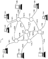
図1は、データを表している信号を複数のデバイスの間で転送するための複数のスイッチングノード11(1) 乃至11(N)(11(n) で総称する)を含んでいるコンピュータネットワーク10を示す概略図であり、図1に示すように、デバイスはコンピュータ12(1) 乃至12(M)(12(m) で総称する)で表されている。コンピュータ12(m) は、従来と同じように、プログラム命令に従ってデータを処理し、処理済みデータを生成する。この処理の際、コンピュータ12(mS)(下付き文字の"S"は「ソース」を表している)は、ソースコンピュータであるときは、データ、処理済みデータおよび/またはプログラム命令(以下では、これらは「情報」と総称することにする)を、別のデスティネーションコンピュータ12(mD)(下付き文字の"D"は「デスティネーション」を表している)に転送する必要が起こることがあり、また、デスティネーションコンピュータは転送されてきた情報をそのオペレーションで使用する必要が起こることがある。各コンピュータ12(m) は、全体を符号13(p) で示している通信リンクを利用してスイッチングノード11(n) に接続され、スイッチングノードとの間のデータの送受信を容易化している。スイッチングノード11(n) はコンピュータ12(m) からや、他のスイッチングノード11(n) から送られてきたデータを受信し、バッファに格納し、転送することによって、コンピュータ12(m) 間のデータ転送を容易化している。スイッチングノード11(n) は、これも全体を符号13(p) で示している通信リンクで相互接続され、その間のデータ転送を容易化している。通信リンク13(p) は、都合の良いものであれば、どのデータ伝送媒体でも利用することが可能である。図1に示す各通信リンク13(p) は双方向であることが好ましく、そのようにすると、スイッチングノード11(n) は相互間に、および同一リンクを利用してそこに接続されたコンピュータ12(m) との間で信号を送受信することができる。この双方向通信リンクを取り入れるために、通信リンク13(p) ごとに別の媒体を設けると、各通信リンクは信号を単方向に転送することが可能になる。
【0008】
一実施形態では、データは周知の "ATM"("Asynchronous Transfer Mode":非同期転送モード)転送技法を使用して転送される。この技法は、C. Partridge著「ギガビットネットワーキング(Gigabit Networking)」(Reading MA: Addison Wesley Publishing Company, 1994)の主に第3章と第4章、およびD. McDysan他著「ATMの理論と応用(ATM Theory and Application)」(McGraw Hill, 1995) に詳しく説明されているので、ここで詳しく説明することは省略する。一般的に、ATM技法では、コンピュータ12(m) とスイッチングノード11(n) は、ネットワークを通してコンピュータ間に確立された「仮想回線(virtual circuit)」を利用してデータを固定長「セル(cell)」の形で伝送している。各仮想回線は、基本的に、ソースコンピュータ12(mS) からデスティネーションコンピュータ12(mD) へのパスを、1つまたは2つ以上のスイッチングノード11(n) を通って、それぞれの通信リンク13(p) を利用するように定義している。ATMデータ転送技法では、ある情報ブロックがソースコンピュータ12(mS) からデスティネーションコンピュータ12(mD) あてに、その間に確立された仮想回線を利用して転送されるとき、ソースコンピュータ12(mS) はそのデータブロックを1つまたは一連の「セル」に割り当てて、通信リンク13(p) 上をシリアルに伝送するようにする。ネットワーク10を通して転送される各セルはヘッダ部分とデータ部分を含み、ヘッダ部分は、ネットワーク10を通るセルの転送を制御するための仮想回線ID情報のほかに、プロトコルおよび他の制御情報(「メッセージ終わり(end of message EOM)」フラグなど)も含んでいる。データ部分は、セルに入って転送されるデータブロックのデータを収めている。各セルのデータ部分はあらかじめ決めた固定長になっており、一実施形態では、48バイトになっている。ソースコンピュータ12(mS) はデータをセルのデータ部分に埋め込むか(転送されるデータブロックが1つのセルに収容される場合)、あるいはブロックに含まれるデータ量が各セルのデータ部分のサイズの整数倍になっていない場合、一連のセルの最終セルに埋め込むことによって(転送されるデータブロックを収容するために複数のセルが必要な場合)、最終セルのデータ部分が必要とする長さを有するようにしている。データブロックを転送するために一連のセルが必要なときは、ソースコンピュータ12(m) は、一連のセルのデータ部分が転送されるデータブロック内のデータの順序に一致するようにセルを送信する。さらに、これらのセルがデスティネーションコンピュータ12(mD) に正しく転送されると、デスティネーションコンピュータはセルを同じ順序で受信することになる。一連のセルの中で、データブロックからの情報を収めている最終セルでは、ヘッダ部分のメッセージ終わりフラグがセットされるので、データブロックのデータを収めているセルのすべてを受信したことがデスティネーションコンピュータ12(mD) に通知される。
【0009】
本発明は、コンピュータ12(m) とスイッチングノード11(n) がネットワーク上のセルのフローを制御し、スイッチングノード11(n) 側とデスティネーションコンピュータ側の双方で輻輳が起こるのを防止または低減するための構成を提供している。このような構成がないと、セル転送スループットが低下し、あるいはネットワーク上でセルが紛失するおそれがある。さらに、本発明は、コンピュータ12(m) とスイッチングノード11(n) によるオペレーションをスケジュールすることによって情報転送の公平性が全体的に保たれるようにすると共に、ネットワーク10を通して確立された種々の仮想回線を利用した小さなメッセージの転送の遅れを妥当な範囲に留めるようにする構成を提供している。一般的に、フロー制御に関しては、コンピュータ12(m) とスイッチングノード11(n) は、フロー制御を2つのモードで実現している。本明細書では、一方は仮想回線フロー制御モード (virtual circuit flow control mode)、他方はリンクフロー制御モード (link flow control mode) と呼ぶことにする。仮想回線フロー制御モードでは、仮想回線に対してデスティネーションコンピュータ12(mD) として動作しているコンピュータ12(m) が余りに高速レートでその仮想回線に関連するセルを受信するために、処理できない場合には(これについては下述する)、仮想回線フロー制御モードで動作しているデスティネーションコンピュータ12(mD) はセットされた仮想回線フロー制御ステートに入るので、仮想回線のフロー制御が可能になる。このオペレーションでは、デスティネーションコンピュータ12(mD) はセットされた仮想回線フロー制御メッセージを生成し、仮想回線のパス上を上流側に、つまり、仮想回線のソースコンピュータ12(mS) に向かってそのメッセージを伝送する。デスティネーションコンピュータ12(mD) からソースコンピュータ12(mS) へ向かう仮想回線のパス上の各スイッチングノード11(n) も、その仮想回線に対してセットされた仮想回線フロー制御ステートに入る。仮想回線のソースコンピュータ12(mS) がセットされた仮想回線フロー制御メッセージを受信すると、その仮想回線に関連するセルの送信を事実上停止する。
【0010】
仮想回線のパス上の各スイッチングノード11(n) は、例えば、余りに高速レートで仮想回線に関連するセルを受信するために、仮想回線のパス上を下流側に転送できない場合も(これについては下述する)、仮想回線フロー制御モードで動作しているとき、セットされた仮想回線フロー制御ステートに入って、セットされた仮想回線フロー制御メッセージを生成し、その仮想回線のパス上を上流側にそのメッセージを送信することができる。デスティネーションコンピュータ(m D )からソースコンピュータ12(m S ) に向かう仮想回線のパス上の上流側スイッチングノード11(n)(存在する場合)は上述したのと同じように動作する。
【0011】
デスティネーションコンピュータ12(mD) がその仮想回線のセルの受信を再開できるようになると、クリアされた仮想回線フロー制御ステートに入るので、クリアされた仮想回線フロー制御メッセージを生成し、その仮想回線のパス上を上流側にそのメッセージを伝送する。スイッチングノード11(n) がクリアされた仮想回線フロー制御メッセージを受信したとき、自身がセットされた仮想回線フロー制御ステートになっていなければ、セットされた仮想回線フロー制御メッセージを、仮想回線のパス上を上流側に向かって、ソースコンピュータ12(mS) に通じるパス上の上流側スイッチングノード11(n)(存在する場合)に伝送するか、あるいは仮想回線のソースコンピュータ12(mS) に伝送する。他方、スイッチングノード11(n) がクリアされた仮想回線フロー制御メッセージを受信した場合、自身がセットされた仮想回線フロー制御ステートにあれば、クリアされた仮想回線フロー制御メッセージの転送を、セットされた仮想回線フロー制御ステートから出るまで延期し、この状態から出ると、クリアされた仮想回線フロー制御メッセージを仮想回線のパス上の上流側に転送する。ソースコンピュータ12(mS) が、クリアされた仮想回線フロー制御メッセージを受信したとき、仮想回線に関連するセルを、仮想回線上の下流側に伝送することを再開することが可能になる。以上から理解されるように、スイッチングノード11(n) がセットされた仮想回線フロー制御ステートにある間、クリアされた仮想回線フロー制御メッセージを仮想回線のパス上を下流側に転送することを延期できるようにすると、スイッチングノード11(n) は、上流側スイッチングノード11(n) またはソースコンピュータ12(mS) がセルをそこに伝送することを再開することが可能になる前に、仮想回線のセルを転送できるので、仮想回線に対してバッファに格納しておく必要のあるセルの数が低減されることになる。
【0012】
リンクフロー制御モードは、仮想回線ごとの単位ではなく、通信リンク単位で実現されている。従って、リンクフロー制御モードでは、コンピュータ12(m) がそこに接続されたスイッチングノード11(n) からセルを、余りに高速レートで受信しているために処理ができない場合には(これにつても下述する)、リンクフロー制御モードで動作しているコンピュータ12(m) はセットされたリンクフロー制御状態に入るので、通信リンクのフロー制御が可能になる。このオペレーションでは、コンピュータ12(m) はセットされたリンクフロー制御メッセージを生成し、そのリンクを利用してそこに接続されたスイッチングノード11(n) にそのメッセージを送信する。スイッチングノード11(n) はセットされたリンクフロー制御メッセージを受信すると、そのリンクを利用してセルをそこに送信することを停止する。同様に、各スイッチングノード11(n) は、例えば、余りに高速レートでセルを受信しているため転送できない場合も(これについても下述する)、リンクフロー制御モードで動作しているとき、セットされたリンクフロー制御ステートに入って、それぞれのセットされたリンクフロー制御メッセージを生成し、他のスイッチングノード11(n) またはそこに接続されていて、そこにセルを送信しているコンピュータ12(m) にこれらのメッセージを送信する。これらのスイッチングノード11(n) またはコンピュータ12(m) がセットされたリンクフロー制御メッセージを受信したときも、それぞれのセットされたリンクフロー制御メッセージが送られてきたスイッチングノード11(n) にセルを送信することを停止する。
【0013】
コンピュータ12(m) が通信リンク13(p) を利用してスイッチングノード11(n) からセルを受信することを再開できるようになると、クリアされたリンクフロー制御ステートに入って、クリアされたリンクフロー制御メッセージを生成し、スイッチングノード11(n) にそのメッセージを送信する。スイッチングノード11(n) がクリアされたリンクフロー制御メッセージを受信すると、コンピュータ12(m) にセルを送信することを再開できるようになる。同様に、セットされたリンクフロー制御ステートで動作しているスイッチングノード11(n) がセルを受信することを再開できるようになると、クリアされたリンクフロー制御ステートに入って、それぞれのクリアされたリンクフロー制御メッセージを生成し、スイッチングノード11(n) および/またはそこに接続されたコンピュータ12(m) にそのメッセージを送信することが可能になる。どちらの場合も、スイッチングノード11(n) とコンピュータ12(m) は、それぞれのクリアされたリンクフロー制御メッセージを受信すると、クリアされたリンクフロー制御メッセージが送られてきたスイッチングノード11(n) またはコンピュータ12(m) にセルを送信することを再開できるようになる。
【0014】
仮想回線フロー制御モードとリンクフロー制御モードが別々になっていると、いくつかの利点が得られる。例えば、仮想回線フロー制御モードを使用すると、各デスティネーションコンピュータ12(mD) が終端となっている仮想回線や、各スイッチングノード11(n) がパスの一部となっているような仮想回線の間で、ネットワークを通るセル伝送バンド幅の公平性が全体的に保たれるようになる。また、仮想回線フロー制御モードを使用すると、過剰の輻輳が起こる可能性を低減することもできる。他方、リンクフロー制御モードを使用すると、過剰の輻輳が実際に起こったとき、そこに格納されているバッファにあふれを引き起こし、そのためにセルを紛失させるようなレートで、セルがコンピュータ12(m) またはスイッチングノード11(n) によって受信される可能性が防止され、あるいは少なくともその可能性が低減される。一実施形態では、種々のフロー制御メッセージ、すなわち、セットおよびクリアされた仮想回線フロー制御メッセージとセットおよびクリアされたリンクフロー制御メッセージは相対的に短いメッセージになっており、そこには、メッセージのタイプ、つまり、セットされた仮想回線フロー制御メッセージであるか、クリアされた仮想回線フロー制御メッセージであるか、セットされたリンクフロー制御メッセージであるか、クリアされたリンクフロー制御メッセージであるか、を示すメッセージタイプフラグとID部分が含まれている。ID部分があらかじめ決めた値、つまり、一実施形態では「ゼロ」になっているときは、そのメッセージは、メッセージタイプフラグの値に応じて、セットまたはクリアされたリンクフロー制御メッセージである。他方、ID部分があらかじめ決めた値とは別の値になっているときは、そのメッセージも、メッセージタイプフラグの値に応じて、セットまたはクリアされた仮想回線フロー制御メッセージであり、ID部分のその値は、そのメッセージがどの仮想回線と関連付けられているかを示している。セットおよびクリアされた仮想回線とリンクフロー制御メッセージは相対的に短いので、メッセージを転送するには、ネットワークを通る少量のバンド幅だけで十分である。
【0015】
システム10で使用されるフロー制御構成を詳しく説明する前に、システム10の一実施形態で使用されるコンピュータ12(m) とスイッチングノード11(n) の構造と動作について説明することにする。図2は、ネットワーク10に関連して使用されるコンピュータ12(m) を示す機能ブロック図であり、図3は、ネットワーク10に関連して使用されるスイッチングノード11(n) を示す機能ブロック図である。一般的に、コンピュータ12(m) は従来のどのタイプのコンピュータにすることも可能であり、その中には、従来のパーソナルコンピュータやコンピュータワークステーション、サーバコンピュータ、ミニまたはメインフレームコンピュータ、などが含まれている。図2に示すように、コンピュータ12(m) は、プロセッサ20、システムメモリ21、大容量記憶サブシステム22、入出力サブシステム23およびネットワークインタフェース24を搭載し、これらはすべて相互接続構成25によって相互接続されている。一実施形態では、相互接続構成25は従来のPCIバスを含んでいる。プロセッサ20は、オペレーティングシステムの制御の下で1つまたは2つ以上のアプリケーションプログラムを処理する。ネットワーク10を利用してデータが転送される特定のコネクションでは、
【0016】
(i) コンピュータ12(m) がソースコンピュータ12(mS) として動作しているときの転送では、プロセッサは、システムメモリ21内にバッファ(単独には示していない)を設定し、デスティネーションコンピュータ12(mD) となる他のコンピュータに転送されるデータブロックをそこにロードできるようになっている。
【0017】
(ii) コンピュータ12(m) がデスティネーションコンピュータ12(mD) として動作しているときの転送では、プロセッサはシステムメモリ内にバッファ(これも単独には示していない)を設定し、ソースコンピュータ12(mS) となる他のコンピュータから受信したデータブロックをそこに格納しておくことができる。説明したように、この一実施形態については、仮想インタフェースアーキテクチャ (Virtual Interface Architecture VIA) 規格バージョン1(1997年12月16日)(Compaq Computer Corp.、Intel Corp、およびMicrosoft Corp発行)に記載されている。
【0018】
大容量記憶サブシステムは、一般的に、プロセッサ20によって処理可能な情報を長期間保存しておくことができる。大容量記憶サブシステム22としては、ディスクまたはテープサブシステム、光ディスク記憶デバイス、CD-ROMのように、情報をそこにストアすることができ、および/またはそこから情報を取り出すことができるデバイスにすることができる。また、大容量記憶サブシステム22は、オペレータによる取り外しと取り付けが可能である、取り外し可能記憶媒体を利用することが可能であるので、オペレータはプログラムとデータをコンピュータ12(m) にロードし、処理済みデータをそこから取り出すことができる。
【0019】
入出力サブシステム23は、一般に、オペレータとデジタルコンピュータ10とのインタフェースとなっている、オペレータ入出力サブシステムを含んでいる。具体的には、オペレータ入力サブシステムは、例えば、キーボードとマウスデバイスを含み、オペレータは対話方式で情報をデジタルコンピュータ10に入力し、処理させることができる。さらに、オペレータ入力サブシステムは、オペレータがデジタルコンピュータ10を制御できるようにするメカニズムを備えていることもある。オペレータ出力サブシステムは、ビデオディスプレイデバイスのように、デジタルコンピュータ10が、マイクロコンピュータ11の制御の下で、そこから処理結果をオペレータに表示するデバイスを備えることができる。さらに、ハードコピーでオペレータに出力するプリンタを備えることも可能である。
【0020】
ネットワークインタフェース24は、デスティネーションコンピュータ12(mD) として動作する他のコンピュータに転送されるデータをシステムメモリ21から取り出し、それからセルを生成し、生成されたセルを通信リンク13(p) を利用して転送する。さらに、ネットワークインタフェース24は、通信リンク13(p) からセルを受信し、そこからデータを抽出し、そのデータをシステムメモリ21内の該当バッファに転送し、そこにストアしておく。ネットワークインタフェース24は複数のコンポーネントを含み、その中には、受信セクション30、送信セクション31、システムインタフェース回路32およびフロー制御回路33が含まれている。受信セクション30は通信リンク13(p) に接続され、通信リンクから送られてきたセルを受信し、受信したセルからのデータをバッファに格納し、システムインタフェース回路32と協力して、バッファに格納されたデータを、相互接続構成25を利用してシステムメモリ21に転送し、コンピュータ12(m) によって生成されるアプリケーションによる使用に備えてストアしておく。送信セクション31はシステムインタフェース回路32と協力して、システムメモリ21から相互接続構成25を利用して転送されるデータを取り出し、セルを生成し、そのセルを通信リンク13(p) を利用して伝送する。一実施形態では、システムインタフェース回路32はDMA(direct memory access)と同じように動作し、システムメモリ21からデータを取り出し、送信セクション31によって送信されるようにすると共に、受信セクション30で受信されたデータをシステムメモリ21に転送し、そこにストアしておく。システムインタフェース回路32も、プロセッサ20から制御情報を受信し、それを種々の制御レジスタ(図示せず)に格納しておくように動作する。制御レジスタは、受信セクション30、送信セクション31、フロー制御回路33のオペレーションだけでなく、システムインタフェース回路32自身のオペレーションも制御している。
【0021】
上述したように、受信セクション30は、コンピュータ12(m) に接続された通信リンク13 (p) からセルを受信し、受信したセルからのデータをバッファに格納し、システムインタフェース回路32と協力して、バッファに格納されたデータをシステムメモリ21に転送し、そこにストアしておくように動作する。受信セクションはいくつかのコンポーネントを含み、その中には、ネットワーク受信インタフェース回路40、受信バッファ41、受信ホスト回路42、受信スケジューラ43および受信仮想回路制御回路44が含まれている。ネットワーク受信インタフェース回路40は"CELLS IN" と名付けられたセルを、コンピュータ12(m) に接続された通信リンク13(p) から受信し、各セルのデータ部分内のデータを受信バッファ41に格納しておく。上述したように、セルはネットワーク10を通るように仮想回線上を伝送されるので、ネットワーク受信インタフェース回路40は、特定の仮想回路に関連するセルからのデータを、受信バッファ41に集約しておくのが一般である。一実施形態では、受信バッファ41に格納されていて、特定の仮想回線に関連するデータはリンクリスト (linked list) にストアされ、ネットワーク受信インタフェース回路40が特定の仮想回線に関連するセルを受信すると、そのセルからのデータを受信バッファに格納しておき、そのセルが関連付けられていた仮想回線に関連するリンクリストの最後にそのデータをリンクするようにしている。
【0022】
受信仮想回線制御回路44は、そこを通ってセルがネットワークインタフェース24に送られてきた各仮想回線の情報をストアしておく。そのような情報としては、各々の仮想回線ごとに、送られてきたデータをストアしておくシステムメモリ21内のロケーションを指すポインタと、仮想回線、およびその仮想回線に関連し、そのデータが現在受信バッファ41に格納されている受信セルの数を示しているバッファ内セル数の値に関連するリンクリストがあれば、そのヘッドおよびテールのロケーションを指すポインタとが含まれている。受信バッファ41が特定の仮想回線に関連するセルからの、どのデータも格納していない間は、受信仮想回線制御回路44は仮想回線にリンクリストが存在しないことを示しているが、仮想回線に関連する少なくとも1つのセルからのデータが存在する間は、受信仮想回線制御回路44は仮想回線のリンクリスト情報を収めている。以上から理解されるように、受信バッファ41が特定の仮想回線に関連する1つのセルだけからのデータを格納しているときは、ヘッドポインタとテールポインタは同じロケーションを指している。つまり、そのデータをストアしている受信バッファ41内のロケーションを指している。受信セルからのデータがネットワーク受信インタフェース回路40にあって、そのデータが受信バッファ41に格納されているときは、ネットワーク受信インタフェース回路40は、受信仮想回線制御回路44内の情報を使用して、仮想回線にリンクリストが存在するかどうかを判断することができる。受信仮想回線制御回路44が仮想回線にリンクリストが存在しないことを示している場合は、ネットワーク受信インタフェース回路40は、セルからのデータがストアされていた受信バッファ41内のロケーションを指すポインタを、リンクリストのヘッドとテールの両ポインタとして受信仮想回線制御回路44にロードし、バッファ内セル数の値をインクリメントすることができる。この条件では、バッファ内セル数の値は「1」になる。他方、リンクリストが存在することを受信仮想回線制御回路44が示していれば、ネットワーク受信インタフェース回路40はストアしたばかりのデータを、仮想回線に関連するリンクリストのテールにリンクし、仮想回線のほうは受信セルと関連付けられる。さらに、ネットワーク受信インタフェース回路40は、受信仮想回線制御回路44内のテールポインタを、ストアしたばかりのデータのロケーションをリンクリストの新しいテールとして指すように更新する。
【0023】
受信ホスト42はバッファ内データを受信バッファ41から取り出し、システムインタフェース回路31と協力して、そのバッファ内データを、相互接続構成25を利用してシステムメモリ21に転送してストアしておく。受信ホスト42は受信仮想回線制御回路44内の仮想回線情報も利用して、各特定仮想回線に関連していて、ストアのためにシステムメモリ21に転送されるデータが、受信バッファ41内のロケーションを判別する。具体的に説明すると、受信ホスト42が特定の仮想回線の受信バッファ41からデータを取り出して、システムメモリ21に転送しようとするとき、その受信ホスト42は、仮想回線のリンクリストのヘッドロケーションを指しているヘッドポインタを利用することができる。一実施形態では、ネットワークインタフェース24は、1つのセルまたは複数セルのブロックからのバッファ内データを、相互接続構成21を利用して一回の転送でシステムメモリ21に転送することができる。いずれの場合も、受信ホスト42がセルに関連する受信バッファからのデータを、そのセルの仮想回線に関連するリンクリストの先頭から取り出したあと、その受信ホストは受信回線制御回路44によって維持されている仮想回線のヘッドポインタを、仮想回線のデータがストアされている次のロケーションがリンクリストの受信バッファ41にあれば、そのロケーションを指すように更新し、仮想回線のバッファ内セル数の値をデクリメントする。取り出したばかりのデータがその仮想回線の最後のデータであれば、受信ホスト42はバッファ内セル数の値をデクリメントすることにより、仮想回線に関連するリンクリストが受信バッファ41に存在しないことを示すことができる。
【0024】
受信スケジューラ43は、ネットワーク受信インタフェース回路40が受信ホスト42と通信して、受信ホスト42によって実行される上述のオペレーションのスケジューリングを制御できるようにする。また、受信スケジューラ43は、プロセッサ20が受信ホスト42と通信して、コンピュータ12(m) によって処理されるアプリケーションプログラムの制御の下で、受信ホスト42によって実行される、ある種のオペレーションを制御し、例えば、それぞれの仮想回線に関連するセルに入って受信されたデータがシステムメモリ21内のどのバッファにストアされるかを、受信ホスト42に通知する。プロセッサ20、ネットワーク受信インタフェース回路40および受信ホスト42に関連して受信スケジューラ43によって実行されるオペレーションは、図5を参照して以下に説明されている。
【0025】
上述したように、送信セクション31はシステムインタフェース回路32と協力して、相互接続構成25を利用してシステムメモリ21から送信されるデータを取り出し、セルを生成し、そのセルを通信リンク13(p) 上を伝送する。送信セクション31はいくつかのコンポーネントを含み、その中には、送信ホスト50、送信バッファ51、ネットワーク送信インタフェース回路52、送信スケジューラ53、および送信仮想回線制御回路54が含まれている。
【0026】
送信ホスト50は、システムインタフェース回路31と協力して、通信リンク13(p) 上をセルに入れて送信されるデータを、システムメモリ21から相互接続構成25を利用して取り出し、それを(つまり、取り出したデータを)送信バッファ51に格納する。送信仮想回線制御回路54は各仮想回線の情報をストアするが、この情報の中には、送信されるデータがそれぞれの仮想回線に関して取り出されるシステムメモリ21内のロケーションを指すポインタと、仮想回線ステータス(状況)情報が含まれている。受信バッファ41と同じように、送信バッファ51は、特定の仮想回線に関連するセルに入れて送信されるデータを集約してリンクリストに入れておき、送信仮想回線制御回路54は、リンクリストのヘッドポインタとテールポインタ、および送信バッファが送信されるデータを格納しようとしている各仮想回線のバッファ内セル数の値もストアしている。従って、送信ホスト50が転送されようとするデータで、特定の仮想回線に関連付けられていているデータを送信バッファ51にストアするとき、送信仮想回線制御回路54内の仮想回線の情報にアクセスし、仮想回線に関連する送信バッファにリンクリストが存在するかどうかを判断する。そのようなリンクリストが存在しないと送信ホスト50が判断したときは、つまり、仮想回線に関連するバッファ内セル数の値が「ゼロ」の値になっているときは、その送信ホスト50は、データがストアされている送信バッファ51内のロケーションを指すポインタが、仮想回線のヘッドとテールの両ポインタとなるようにし、送信仮想回線制御回路54内のバッファ内セル数の値をインクリメントすることができる。他方、送信バッファ51にストアしたばかりのデータが送信される仮想回線にリンクリストが存在すると送信ホスト50が判断したときは、その送信ホスト50は、受信仮想回線制御回路44によって維持されている仮想回線のテールポインタを、データがストアされていた送信バッファ51内のロケーションを指すように更新し、仮想回線のバッファ内セル数の値をインクリメントする。
【0027】
ネットワーク送信インタフェース回路52は送信バッファ51からデータを取り出し、"CELLS OUT" と名付けたセルをそのデータから生成し、コンピュータ12(m) に接続された通信リンク13(p) を利用して送信する。このオペレーションでは、ネットワーク送信インタフェース回路52が特定の仮想回線に関連するデータを送信バッファ51から取り出すとき、仮想回線に関連するリンクリストの先頭からデータを取り出し、このオペレーションでは、その特定仮想回線の送信仮想回線制御回路54にストアされているリンクリスト情報、具体的にはヘッドポインタを使用する。ネットワーク送信インタフェース回路52がセルに関連する送信バッファ51からのデータを、そのセルの仮想回線に関連するリンクリストの先頭から取り出したあと、このネットワーク送信インタフェース回路52は送信仮想回線制御回路54によって維持されている仮想回線のヘッドポインタを、データが仮想回線に関してストアされている次のロケーションがリンクリストの受信バッファ41にあれば、そのロケーションを指すように更新し、仮想回線のバッファ内セル数の値をデクリメントする。取り出したばかりのデータが仮想回線の最後のデータであれば、ネットワーク送信インタフェース回路52は、バッファ内セル数の値をゼロにデクリメントすることにより、仮想回線に関連するリンクリストが送信バッファ51にないことを示すことができる。
【0028】
送信スケジューラ53は、送信ホスト50がネットワーク送信インタフェース回路52と通信して、ネットワーク送信インタフェース回路52によって実行される上述のオペレーションのスケジューリングを制御できるようにする。また、送信スケジューラ53は、プロセッサ20が送信ホスト50と通信して、コンピュータ12(m) によって処理されるアプリケーションプログラムの制御の下で送信ホスト50による、ある種のオペレーションを制御し、例えば、それぞれの仮想回線に関連するセルに入れて送信されるデータが、システムメモリ21内のどのバッファにストアされているかを送信ホスト50に通知できるようにする。送信スケジューラ53に関連してプロセッサ20、送信ホスト50およびネットワーク送信インタフェース回路52によって実行されるオペレーションは、図6を参照して以下に説明されている。
【0029】
本発明の一側面によれば、フロー制御回路33は、以下に関連するいくつかのオペレーションを実行する。
【0030】
(i) 送信セクション31によるセルの伝送レートを制御する。
【0031】
(ii) 送信セクションが仮想回線フロー制御メッセージとリンクフロー制御メッセージを、必要におじて通信リンク13(p) を利用して送信できるようにする。
【0032】
上記 (i) に関しては、フロー制御回路33は、
(a) セットされた仮想回線フロー制御メッセージを受信したあと、クリアされた仮想回線フロー制御メッセージが受信されるまで送信セクション31が特定の仮想回線に関連するセルを送信することを禁止する。セットされた仮想回線フロー制御メッセージを受信したあと、フロー制御回路33は、送信ホスト50がシステムメモリ21からデータを取り出し、そのデータをその仮想回線を利用して送信することを禁止する(一実施形態では、ネットワーク送信インタフェース52は、以前に取り出されたデータで、送信バッファ51に格納されているデータのセルの送信を続けることが可能になっている)。
【0033】
(b) セットされたリンクフロー制御メッセージを受信したあと、クリアされたリンクフロー制御メッセージが受信されるまでネットワーク送信インタフェース52がセルを通信リンク13(p) を利用して送信することを禁止する。
【0034】
上記 (ii) に関しては、フロー制御回路33は、ネットワーク送信インタフェース52によって送信されるセットおよびクリアされた仮想回線とリンクフロー制御メッセージを、受信バッファ41に置かれている総データ量(以下では、「総受信バッファ占有レベル(total receive buffer occupancy level)」と呼ぶことにする)と特定の仮想回線の受信バッファ41に格納されているデータ量(以下では、仮想回線ごとの受信バッファ占有レベル(per-virtual circuit receive buffer occupancy level))と呼ぶことにする)に基づいて生成し、フロー制御回路33は、受信仮想回路制御回路44内の情報に基づいてデータ量を判断することができる。フロー制御回路33によって実行されるある種のオペレーションは、図4に示すフロー図を参照して以下に説明されている。一般的に、フロー制御回路33は4つのステート(状態)で動作するが、その4ステートとは、非フロー制御(non-flow controlled) ステート、通常輻輳(normal congestion) ステート、中輻輳(medium congestion) ステート、および高輻輳(high congestion) ステートである。これらのステートは、種々のしきい値を基準にした総受信バッファ占有レベルによって判断される。従って、フロー制御回路33は、総受信バッファ占有レベルが相対的に低い「非フロー制御」しきい値以下にあれば、非フロー制御ステートで動作することになる。他方、フロー制御回路33は、総受信バッファ占有レベルが非フロー制御しきい値と若干高い「輻輳モード」しきい値の間にあれば、通常輻輳ステートで動作し、総受信バッファ占有レベルが輻輳モードしきい値と相対的に高い「リンクモード」しきい値の間にあれば、中輻輳ステートで動作し、総受信バッファ占有レベルがリンクモードしきい値以上であれば、高輻輳ステートで動作することになる。フロー制御回路33は、
(a) 非フロー制御ステートで動作しているときは、ネットワーク送信インタフェース回路52がセットされた仮想回線またはリンクフロー制御メッセージを送信するのを禁止し、仮想回線ID順のラウンドロビン方式で、セットされた仮想回線フロー制御ステートにある仮想回線をクリアされた仮想回線フロー制御ステートにし、ネットワーク送信インタフェース回路52がそのためにクリアされた仮想回線フロー制御メッセージを送信することを可能にする。
【0035】
(b) 通常輻輳ステートで動作しているときは、
(I) その仮想回線ごとの受信バッファ占有レベルが選択した仮想回線ごとの総受信バッファフロー制御しきい値以上にある各仮想回線については、仮想回線をセットされた仮想回線フロー制御ステートにし、ネットワーク送信インタフェース回路52がそのためにセットされた仮想回線フロー制御メッセージを送信することを可能にする。しかし、
(II) セットされた仮想回線フロー制御ステートにあるが、その仮想回線ごとの受信バッファ占有レベルが選択した仮想回線ごとの受信バッファフロー制御しきい値以下にある仮想回線については、仮想回線ID順のラウンドロビン方式で、仮想回線をクリアされた仮想回線フロー制御ステートにし、ネットワーク送信インタフェース回路52がそのためにクリアされた仮想回線フロー制御メッセージを送信することを可能にする。
【0036】
(c) 中輻輳ステートで動作しているときは、受信セクションがセルを受信するときの各仮想回線をセットされた仮想回線フロー制御モードにし、ネットワーク送信インタフェース回路52がそのためにセットされた仮想回線フロー制御メッセージを送信するのを可能にする。
【0037】
(d) 高輻輳ステートで動作しているときは、ネットワーク送信インタフェース回路52がそのためにセットされたリンクフロー制御メッセージを送信することを可能にする。
フロー制御回路33が高輻輳ステートから他のステートのいずれかにシーケンスした場合は、ネットワーク送信インタフェース回路52がそのためにクリアされたリンクフロー制御メッセージを送信することを可能にする。通常輻輳ステートにあるとき、セットされた仮想回線フロー制御ステートにあるが、その仮想回線ごとの受信バッファ占有レベルが選択した仮想回線ごとの受信バッファフロー制御しきい値以下にある仮想回線を、仮想回線ID順のラウンドロビン方式でクリアされた仮想回線フロー制御ステートにシーケンスするようにすると、フロー制御回路33は、仮想回線間である程度の公平性が得られるようにする。
【0038】
クリアされた仮想回線とリンクフロー制御メッセージを生成し、送信するかどうかを判断するためにフロー制御回路33によって実行されるオペレーションは、図4に示すフローチャートを参照して以下に説明されている。図4に示すように、フロー制御回路33は、まず、仮想回線ポインタを設定し、初期化し(ステップ100)、このポインタは、仮想回線をセットされた仮想回線フロー制御ステートからクリアされた仮想回線フロー制御ステートに仮想回線ID順のラウンドロビン方式でシーケンスするとき使用される。そのあと、フロー制御回路33は、セットされた仮想回線フロー制御ステートにある仮想回線があるかどうかを判断する(ステップ101)。フロー制御回路33がステップ101で否定の判断をしたときは、セットされた仮想回線フロー制御ステートからクリアされた仮想回線フロー制御ステートにシーケンスする必要のある仮想回線がないために、フロー制御回路33はステップ101に戻ることになる。
【0039】
他方、フロー制御回路33がステップ101で肯定の判断をしたときは、セットされた仮想回線フロー制御ステートからクリアされた仮想回線フロー制御ステートにシーケンスする必要のある仮想回線があるために、フロー制御回路33は、中または高輻輳ステートで動作しているかどうかを判断する(ステップ102)。フロー制御回路33が高または中輻輳ステートで動作している間は、どの仮想回線もセットされた仮想回線フロー制御ステートからクリアされた仮想回線フロー制御ステートにシーケンスすることがないので、フロー制御回路がステップ102で肯定の判断をしたときは、ステップ101に戻ることになる。
【0040】
他方、フロー制御回路33がステップ102で否定の判断をしたときは、非フロー制御ステートまたは通常輻輳ステートで動作しているので、その仮想回線ごとの受信バッファ占有レベルが選択した仮想回線受信バッファフロー制御しきい値以下にある仮想回線を、仮想回線ID順のラウンドロビン方式でクリアされた仮想回線フロー制御ステートにシーケンスし、ネットワーク送信インタフェース回路52がクリアされた仮想回線フロー制御メッセージを、それに対し送信することを可能にする。従って、フロー制御回路33がステップ102で否定の判断をしたときは、ステップ100で設定された仮想回線ポインタを、セットされた仮想回線フロー制御ステートにある、次の仮想回線を指すようにインクリメントする(ステップ103)。そのあと、フロー制御回路33は非フロー制御ステートで動作しているかどうかを判断し(ステップ104)、動作していれば、仮想回線ポインタが指している仮想回線をクリアされた仮想回線フロー制御ステートに配置し(ステップ105)、ネットワーク送信インタフェース42がクリアされた仮想回線フロー制御メッセージを、それに対して送信することを可能にする(ステップ106)。そのあと、フロー制御回路33はステップ101に戻る。
【0041】
ステップ104に戻って説明すると、フロー制御回路33が非フロー制御ステートで動作していないと、そのステップで判断した場合は、通常輻輳ステートで動作している。従って、フロー制御回路33は、仮想回線ポインタが指している仮想回線はその仮想回線ごとの受信バッファ占有レベルが、選択した仮想回線ごとの受信バッファ占有レベルしきい値以下にあるかどうかを判断することになる(ステップ107)。フロー制御回路33がそのステップ107で肯定の判断をしたときは、ステップ105にシーケンスして、仮想回線ポインタが指している仮想回線をクリアされた仮想回線フロー制御ステートに配置し、そのあと、ネットワーク送信インタフェース42がクリアされた仮想回線フロー制御メッセージを、それに対して送信することを可能にする(ステップ106)。他方、フロー制御回路33がステップ107で否定の判断をしたときは、仮想回線ポインタが指している仮想回線の仮想回線ごとのバッファ占有レベルは選択したしきい値以上であるので、フロー制御回路33は、仮想回線をクリアされた仮想回線フロー制御ステートに配置することなくステップ101に戻る。
【0042】
図2に戻って説明すると、本発明の別の側面によれば、上述したように、受信スケジューラ43は、ネットワーク受信インタフェース回路40とプロセッサが受信ホスト42と通信して、受信ホスト42によって実行される種々のオペレーションのスケジューリングを制御することを可能にする。受信スケジューラ43は、「ドアベル(doorbell)」タスク、高優先度データ転送タスク、およびメッセージ終わりデータ転送タスクといった、いくつかの高優先度クラスのタスクと、低優先度データ転送タスクといった、1つの低優先度クラスのタスクを用意している。一実施形態では、特定の仮想回線に関連するプロセッサ20(図2)は、特定の仮想回線のために利用可能な制御情報があるとき、「ドアベル」メカニズムを利用して、受信ホスト42または送信ホスト50にシステムインタフェース32を通してそのことを選択的に通知する。ドアベルメカニズムは、受信ホスト42または送信ホスト50の各々のためにワークキュー (work queue)(単独には示されていない)を選択的に用意し、プロセッサ20は、システムメモリ21にストアされている、それぞれの仮想回線の制御ブロック(これも単独には示されていない)を指すポインタをそのワークキューにロードする。各制御ブロック(前記のVIA規格では「記述子(descriptor)」と呼ばれている)は、仮想回線のための種々タイプのコマンドと制御情報を収めており、この中には、例えば、ネットワークインタフェース24がそのデスティネーションとなっている仮想回線に関しては、仮想回線の受信セクション30によって受信されたメッセージのデータがストアされるシステムメモリ21内のそれぞれのバッファを指している1つまたは2つ以上のポインタが含まれており、あるいはネットワークインタフェース24がそのデスティネーションとなっている仮想回線に関しては、仮想回線上を伝送されるデータを収容しているシステムメモリ21内のそれぞれのバッファを指している1つまたは2つ以上のポインタが含まれている。プロセッサ20は、制御ブロックを指しているポインタを、仮想回線に関連するワークキューにロードすることによって、受信ホスト42が仮想回線に関連するドアベルタスクを実行できるようにする。特定の仮想回線に関連するドアベルタスクの実行中に、受信ホスト42はワークキューに置かれている最初のポインタが指している制御ブロックからコマンドと制御情報を取り出し、その処理を行う。受信ホスト42は、カレントドアベルタスクに関して実行される追加作業があれば、仮想回線に関連するドアベルタスクを使用可能にすることもできる。さらに、受信ホスト42は、セットされたメッセージ終わりフラグに関連する受信バッファ41からデータを仮想回線に対して転送していた場合、および仮想回線に関連するワークキューに後続制御ブロックを指すポインタが置かれている場合、仮想回線に関連するドアベルタスクを使用可能にすることができる。このようにすると、受信ホスト42は、例えば、システムメモリ21内の別のバッファを指しているポインタを取得し、そのバッファに仮想回線のデータをストアしておくことができる。
【0043】
仮想回線に関連する高優先度データ転送タスクを使用すると、受信ホスト42は、仮想回線のデータを受信バッファ41からシステムメモリ21に高優先度順に転送することができる。一般的に、受信ホスト42は、あらかじめ決めたデータ量がその仮想回線の受信バッファ41に累積されると、仮想回線のデータをシステムメモリ21に転送する。一実施形態では、このあらかじめ決めた量は、受信ホスト42が高優先度データ転送タスクに従ってデータを転送する場合、データブロックが相互接続構成25上を効率よく転送されるように選択されている。高優先度データ転送タスクは、受信ホスト42自身によって使用可能にすることができるが、ネットワーク受信インタフェース40によって使用可能にされるのが一般的である。ネットワーク受信インタフェース40が仮想回線に関連する高優先度データ転送タスクを使用可能にできるのは、受信バッファ41内の仮想回線のリンクリストにセルからのデータをロードするとき、リンクリスト内のデータ量があらかじめ決めたしきい値にあるか、またはそれ以上になった場合である。さらに、受信ホスト42は、仮想回線に対していずれかのタスクを実行したあと、受信バッファ41内の仮想回線のリンクリストにデータがある場合、仮想回線に関連する高優先度データ転送タスクを使用可能にすることができる。
【0044】
仮想回線に関連するメッセージ終わりデータ転送タスクを使用すると、受信ホスト42は、仮想回線に対してセルが受信され、そのセルがメッセージの最後のセルであるとき、仮想回線のデータを受信バッファ41からシステムメモリに高優先度順に転送することができる。メッセージ終わりデータ転送タスクは、受信バッファ41に累積されたデータ量が高優先度データ転送タスクを使用するのに十分でない場合でも、メッセージ終わりに関するデータが確実にシステムメモリ21に転送されるようにする。ネットワーク受信インタフェース40は、受信バッファ41内の仮想回線のリンクリストにセルからのデータをロードするとき、セルがセットされたメッセージ終わりフラグを含んでいた場合、仮想回線に関連するメッセージ終わりデータ転送タスクを使用可能にすることができる。さらに、受信ホスト42は、仮想回線に対していずれかのタスクを実行したあと、受信バッファ41に格納されている仮想回線のデータがセットされたメッセージ終わりフラグを含んでいたセルからのものであった場合、仮想回線に関連する高優先度データ転送タスクを使用可能にすることができる。
【0045】
最後に、仮想回線に関連する低優先度タスクを使用すると、受信ホストは、仮想回線のデータを受信バッファからシステムメモリ21に低優先度順に転送することができる。仮想回線に対して実行すべき高優先度タスクが受信ホスト42にないときは、受信ホストは低優先度データ転送タスクを実行して、データを仮想回線のシステムメモリに転送する。以上から理解されるように、受信ホスト42が仮想回線に対して低優先度データ転送タスクを使用して、しばらくの間データを転送していないと、仮想回線に対する十分なデータ量が受信バッファ41に累積されるので、高優先度データ転送タスクを使用した転送が保証されることになる。ネットワーク受信インタフェース40は、受信バッファ41内の仮想回線のリンクリストにセルからのデータをロードするとき、仮想回線に関連する低優先度データ転送タスクを使用可能にすることができる。
【0046】
一般的に、受信スケジューラ43は、少なくとも1つのタスクが使用可能にされている仮想回線の中で、受信ホスト42がどの仮想回線に対してタスクを実行すべきかを識別する。受信スケジューラ43は、どの仮想回線に対して高優先度クラスのタスクが使用可能であるかを、仮想回線ID順のラウンドロビン方式で識別する。どの仮想回線に対しても高優先度クラスのタスクが使用可能になっていなければ、受信スケジューラ43は、どの仮想回線に対して低優先度クラスのタスクがスケジュールされているかを、この場合も、仮想回線ID順のラウンドロビン方式で識別する。いずれの場合も、受信スケジューラ43は、どの仮想回線に対してタスクが実行されるかを、そのIDで受信ホスト42に知らせるようになっている。受信ホスト42側は、通知された仮想回線に対して高優先度クラスのどのタスクを実行すべきかを、受信仮想回線制御回路43に維持されているその仮想回線のカレントステートに基づいて判断し、そのタスクを実行することになる。仮想回線に対して実行すべき高優先度クラスのタスクがないと受信ホスト42が判断した場合は、受信ホストは低優先度クラスのタスクを実行することになる。受信ホスト42が通知された仮想回線に対して少なくとも1つのタスクを実行したあと、受信ホスト42はそのことを受信スケジューラに通知し、さらに、仮想回線の、そのときのカレントステート(これは、タスクが実行されたあとの仮想回線のステートである)に応じて、その仮想回線に対して後続タスクを使用可能にすることができる。受信スケジューラ43が、受信ホスト42が通知された仮想回線に対してタスクを実行したとの通知をその受信ホスト42から受け取ると、その受信スケジューラ43は、タスクが使用可能にされる次の仮想回線を仮想回線ID順に通知し、そのあと上述したオペレーションが繰り返される。
【0047】
上述したように、受信ホスト42は、どの仮想回線に対してタスクを実行すべきかをそのIDで通知を受けたあと、どのタスクを実行すべきかを、通知された仮想回線のカレントステートから判断する。例えば、転送すべき仮想回線のデータが受信バッファ42にあると受信ホスト42が判断したとき、データをストアしておくシステムメモリ21内のバッファを指すポインタを有しなければ、受信ホスト42は、ポインタを取り出すためにドアベルタスクを実行する。そのあと、受信ホスト42はドアベルタスク、高優先度データ転送タスク、メッセージ終わりデータ転送タスクのいずれかを、仮想回線のバッファに格納されているデータが、メッセージ終わりフラグがセットされていたセルと関連しているかどうかに応じて使用可能にする。他方、どの仮想回線に対してタスクを実行すべきかをそのIDで通知を受けたあと、受信ホストがデータをストアしておくシステムメモリ21内のポインタを有していれば、受信ホストは1ブロックまでのデータを、システムインタフェース32および相互接続構成25上を経由してシステムメモリ21に転送することを開始できる。そのあと、受信ホスト42はドアベルタスク、高優先度データ転送タスク、メッセージ終わりデータ転送タスクのいずれかを、仮想回線のバッファに格納されたデータが、メッセージ終わりフラグがセットされていたセルと関連があるかどうかに応じて使用可能にすることができるが、そうしなくてもよい。
【0048】
図5は、本発明の一実施形態で使用される受信スケジューラ43を示す機能ブロック図である。図5に示すように、受信スケジューラ43は、高優先度データ転送メモリ80(1)、ドアベルメモリ80(2)、メッセージ終わりデータメモリ80(3) および低優先度データ転送メモリ80(4) を含む複数のメモリ、メモリアクセスアービタ (memory access arbiter) 81、タスクコントロール82、および複数のマルチプレクサ83および84を搭載している。メモリ80(1) 乃至80(4) の各々は一連のビットを含み、ネットワークインタフェース24がそのデスティネーションとなっている仮想回線ごとに1ビットが割り当てられている。一実施形態では、仮想回線IDは10ビットであるので、各メモリ80(1) 乃至80(4) は1024(つまり、210)ビットからなり、各ビットは、仮想回線が特定の符号化用に設定されているかどうかに関係なく、仮想回線IDの1つの取り得るバイナリ符号化と関連付けられている。この実施形態では、各メモリ内のビット(i)(インデックス"i" はゼロから1023までの範囲)は、ネットワークインタフェース24がデスティネーションとなっているのときの、そのID用に仮想回線が設定されているかどうかに関係なく、ID "i" をもつ仮想回線と関連付けられている。メモリ80(1) 乃至80(4)内の「i番目」ビットがセットされたときは、関連タスク(つまり、高優先度データ転送タスク、ドアベルタスク、メッセージ終わりデータ転送タスクまたは低優先度データ転送タスク)は「i番目」仮想回線に対して使用可能にされる。
【0049】
タスクコントロール82はビットの状態を表す信号をメモリから受信し、RCV_HOST_CTRL受信ホスト制御信号のうち該当する信号を通して、どの仮想回線に対して受信ホスト42にタスクを実行させるかを通知する。さらに、タスクコントロール82は、メモリ80(1) 乃至80(4)の1つの中の、通知された仮想回線に関連するビットのリセットを行う。タスクコントロール82がどの仮想回路であるかを、メモリ80(1) 乃至80(3)の1つの中の、仮想回線のビットがセットされていることに基づいて識別した場合は、タスクコントロール82は、メモリ80(1) 乃至80(3)の1つの中の、仮想回線のビットがリセットされるようにするが、このリセットはメモリ80(1) 乃至80(3)の間で、ラウンドロビン方式で行われる。タスクコントロール82は、HI_PRI_TASK_RST_REQ高優先度タスクリセット要求信号、DOORBELL_TASK_RST_REQドアベルタスクリセット要求信号、LOW_PRI_TASK_RST_REQ低優先度タスクリセット要求信号のうち該当する信号をアサートすることによって、このオペレーションを使用可能にし、その信号はマルチプレクサ83によってマルチプレクサ84の一方の入力に結合される。マルチプレクサ84の方は、この信号をSEL_TASK_RST_REQ選択タスクリセット要求信号としてメモリアクセスアービタ81に結合する。アービタがSEL_TASK_RST_REQ信号を選択したときは、メモリ80(1) 乃至80(3)のうちの、該当メモリの仮想回線のビットがリセットされる。
【0050】
他方、タスクコントロール82がどの仮想回線であるかを、メモリ80(4) 内の仮想回線のビットがセットされていることに基づいて識別した場合は(これは、受信ホスト42に低優先度データ転送タスクを実行させる場合である)、タスクコントロール82は、メモリ80(4) 内の仮想回線のビットがリセットされるようにする。タスクコントロール82は、LOW_PRI_TASK_RST_REQ低優先度タスクリセット要求信号をアサートすることによって、このオペレーションを使用可能にし、この信号はマルチプレクサ84の一方の入力に結合される。マルチプレクサ84の方は、信号をSEL_TASK_RST_REQ選択タスクリセット要求信号としてメモリアクセスアービタ81に結合する。アービタがSEL_TASK_RST_REQ信号を選択したときは、メモリ80(4) の仮想回線のビットがリセットされる。
【0051】
システムインタフェース32を経由するプロセッサ20からのドアベル要求に応答して、あるいはネットワーク受信インタフェース40または受信ホスト42からのドアベル要求に応答してメモリにアクセスして、メモリ内のビットのセットを容易にすることも、メモリアクセスアービタ81によって制御される。ネットワーク受信インタフェース40とシステムインタフェース32からは、特定の仮想回線に対する、それぞれのNWK_RCV_INTF_REQ受信インタフェース、SYS_INTF_REQシステムインタフェース、およびRCV_VC_CTRL_REQ受信仮想回線制御セット要求をメモリアクセスアービタ81に対して出して、その特定仮想回線に関連するメモリ80(1) 乃至80(4) の1つの中のビットをセットする。メモリアクセスアービタ81がNWK_RCV_INTF_REQ、SYS_INTF_REQまたはRCV_VC_CTRL_REQ要求を選択したときは、メモリ80(1) 乃至80(4)の1つの中のビットがその特定仮想回線に対してセットされる。一般的に、ドアベルメモリ80(2) 内のビットは、システムインタフェース32からのSYS_INTF_REQに応答してセットされ、システムインタフェース32の方は、プロセッサ20からの要求に応答してドアベルタスクを使用可能にする。他方、高優先度データ転送メモリ80(1)、メッセージ終わりデータ転送メモリ80(3) または低優先度データ転送メモリ80(4) 内のビットは、一般的には、ネットワーク受信インタフェース40が特定仮想回線に関連する、1つまたは2つ以上のセルからのデータを受信バッファ41にロードしたあとで、ネットワーク受信インタフェース40からのNWK_RCV_INTF_REQ要求に応答してセットされる。さらに、メモリ80(1) 乃至80(3) のいずれかにあるビットは、受信ホスト42からのRCV_VC_CTRL_SET_REQ要求に応答してセットされ、高優先度データ転送タスク、ドアベルタスクまたはメッセージ終わりデータ転送タスクを、それぞれ使用可能にすることができる。
【0052】
以上から理解されるように、受信スケジューラ43は仮想回線に関して仮想回線ID順のラウンドロビン方式でタスクを実行させるようにするので、受信スケジューラは、それぞれの仮想回線の間である程度の公平性を保つようにしている。さらに、タスクは、ネットワークインタフェース24によって提供される種々のリソースが正しく使用されるような形で実行される。例えば、受信スケジューラ43は、あらかじめ決めた最小データ量が転送ために受信されていない限り、受信ホスト42が特定の仮想回線に関連するシステムメモリにデータを転送することを禁止しているのが通常で、このようにして相互接続構成25が効率よく使用されるようにしている(これは、低優先度転送タスクの場合である)。しかし、受信バッファ41が、少なくともあらかじめ決めた最小データ量を格納している場合は、受信スケジューラ43は、仮想回線に関連するデータがシステムメモリ21に転送されることを可能にする(これは高優先度転送タスクの場合である)。さらに、受信バッファ41が仮想回線を利用したメッセージ終わり転送に関連するデータを格納している場合は、その仮想回線に対して受信された追加データがないか、あるいはその仮想回線に対して後続データが受信されるまで相対的に長い遅延があるために、受信スケジューラ43は仮想回線に関連するデータがシステムメモリ21に転送されることを可能にする(これも、高優先度転送タスクの場合である)。最後に、受信ホストに実行させる他のタスクがない場合は、受信スケジューラ43は受信ホスト42が低優先度転送を実行することを可能にする。
【0053】
上述したように、送信スケジューラ53は送信ホスト50がシステムインタフェース32およびネットワーク送信インタフェース回路52と通信して、ネットワーク送信インタフェース回路52によって実行される、上述のオペレーションのスケジューリングを制御することを可能にする。また、送信スケジューラ53は、プロセッサ20が送信ホスト50と通信して、コンピュータ12(m) によって処理されるアプリケーションプログラムの制御の下で送信ホスト50によるある種のオペレーションを制御することも可能にし、例えば、それぞれの仮想回線に関連するセルに入って送信されるデータが、システムメモリ21内のどのロケーションにストアされているかを送信ホスト50に通知するようにする。
【0054】
一般的に、送信スケジューラ53は送信ホスト50によるデータの取り出しを制御し、ネットワーク送信インタフェース52によるその後の送信に備えてそのデータを送信バッファ51に格納しておくようにする。さらに、上述したように、一実施形態では、特定の仮想回線に関連するプロセッサ20(図2)は「ドアベル」メカニズムを利用して、特定の仮想回線に対して利用可能である制御情報があるとき、そのことを受信ホスト42または送信ホスト50に選択的に通知することにより、送信ホスト50がシステムメモリ21内の仮想回線の制御ブロック(個別には示されていない)から仮想回線の情報を選択的に取り出すことを可能にする。特定の仮想回線に関連するドアベルタスクの実行中に、送信ホスト50は、受信ホスト42に関して上述したのと同じように、仮想回線の制御ブロックからコマンドと制御情報を取り出し、その処理を行う。優先度順に、送信スケジューラ53は送信ホスト50が次のことを行うことを可能にする。
【0055】
(i) 最高優先度順では、あらかじめ決めた数の仮想回線に関連するドアベルタスクを処理すること。この処理はドアベルタスクを実行しようとする仮想回線に対して仮想回線ID順のラウンドロビン方式で行われる。
【0056】
(ii) 中間優先度順では、システムメモリからデータを選択的に取り出し、送信バッファ51にストアしておくこと。この取り出しは、セットされた仮想回線フロー制御モードになっていないか、あるいはそうでなくても、あらかじめ決めた最大数の仮想回線に関して伝送が制限されない仮想回線に対して仮想回線ID順のラウンドロビン方式で行われる。
【0057】
(iii) 最低優先度順では、システムメモリからデータを選択に取り出し、送信バッファ51にストアしておくこと。この取り出しは、伝送が制限されていて、セットされた仮想回線フロー制御モードになっていない仮想回線に対して仮想回線ID順のラウンドロビン方式で行われる。
上記項目 (iii) に関して、伝送が制限されている仮想回線としては、伝送が特定の伝送レートに制限されている仮想回線がある。受信スケジューラ43の場合と同じように、送信スケジューラ53は特定の優先度レベル内にある仮想回線に関して仮想回線ID順のラウンドロビン方式で動作するので、送信スケジューラはその優先度レベルでオペレーションが実行される、それぞれの仮想回線の間で、ある程度の公平性を保証している。さらに、送信スケジューラ53は、優先度レベル内のあらかじめ決めた最大数の仮想回線に関連するオペレーションを実行したあと、次に低い優先度レベルに移るので、送信スケジューラは異なる優先度レベルにある仮想回線の間で、ある程度の公平性を保証している。
【0058】
送信スケジューラ53の機能ブロック図は図6に示されている。図6に示すように、送信スケジューラ53はドアベルメモリ90(1)、2つの高優先度メモリ90(2) と90(3)、低優先度メモリ90(4)、および送信タスクコントロール91を含んでいる。メモリの各々は、それぞれのタスクを実行しようとする仮想回線のIDをストアしており、このIDは送信タスクコントロール91が使用して、送信ホストがそれぞれのタスクを実行できるようにする。メモリ90(1) 乃至90(4) の各々は一連のビットを含み、ネットワークインタフェース24がそのソースとなっている仮想回線ごとに1ビットが割り当てられている。一実施形態では、仮想回線IDは10ビットになっているので、各メモリ90(1) 乃至90(4)は1024(つまり、210)ビットを含み、各ビットは、仮想回線が特定の符号化用に設定されていたかどうかに関係なく、仮想回線IDの1つの取り得るバイナリ符号化と関連付けられている。この実施形態では、各メモリ内のビット(i)(インデックス"i" はゼロから1023までの範囲)は、ネットワークインタフェース24がそのソースとなっている、そのID用に仮想回線が設定されていたかどうかに関係なく、ID "i" をもつ仮想回線と関連付けられている。
【0059】
ドアベルメモリ90(1) は、ドアベルタスクが処理されようとする仮想回線のIDをストアしている。受信スケジューラ43側のドアベルメモリ80(1) の場合と同じように、仮想回線と関連付けられている、送信スケジューラ53側のドアベルメモリ90(1) のビットは、プロセッサ20からのその要求に応答してセットされ、ドアベルタスクが送信セクション31によって実行されるようにする。送信ホスト50が新しいメッセージのデータを取り出して、仮想回線上を送信しようとすると、送信タスクコントロール91は高優先度メモリ90(2) 内にある、仮想回線に関連するビットをセットする。送信しようとするメッセージが相対的に長いときは、送信ホスト50がそのメッセージのデータの一部を取り出したあとで、送信タスクコントロール91は高優先度メモリ90(2) 内にある、仮想回線に関連するビットをリセットし、高優先度メモリ90(3) 内にある、仮想回線に関連するビットをセットする。送信ホスト50が、伝送レートが制限されている仮想回線のデータを取り出そうとしたときは、送信タスクコントロール91は、低優先度メモリ90(4) 内にある、仮想回線に関連するビットをセットする。
【0060】
送信タスクコントロール91はそれぞれのメモリ90(1) 乃至90(4) 内のビットを使用して、どの仮想回線に対してドアベルまたはデータ取り出しオペレーションが、各メモリ内で仮想回線ID順のラウンドロビン方式で実行されるのかを示すようにする。1つまたは2つ以上のビットがドアベルメモリ90(1) 内でセットされ、プロセッサ20がそれぞれの仮想回線に関連してドアベルタスクが実行されることを可能にしていた場合は、送信タスクコントロール91は、送信ホスト50およびシステムインタフェース32と協力して、仮想回線の制御ブロックから情報を取り出し、ドアベルタスクを処理する。メッセージが仮想回線上を送信される場合は、仮想回線が伝送レート制限されていなければ、仮想回線に関連するビットが高優先度メモリ90(2) 内でセットされ、仮想回線が伝送レート制限されていれば、低優先度メモリ90(4) 内でセットされる。これらのオペレーションは、ドアベルメモリ90(1) 内のそれぞれのビットが仮想回線ID順のラウンドロビン方式でセットされている仮想回線に対して繰り返される。
【0061】
あらかじめ決めた数の仮想回線に対してドアベルメモリ90(1) を使用して一連のドアベルタスクが処理されたあとで、メモリ90(2) 乃至90(4) のビットの中にセットされているビットがあり、データがシステムメモリ21から取り出されて少なくとも1つの仮想回線に対して送信されようとしていれば、送信タスクコントロール91は送信ホスト50がそのオペレーションを開始できるようにする。一般的に、これらのオペレーションでは、送信タスクコントロール91は、送信ホスト50が一連の繰り返しで、高優先度メモリの1つ90(2) または90(3) に示されている、あらかじめ決めた数の仮想回線上を送信されるデータを取り出すことを可能にし、そのあとで、低優先度メモリ90(4) に示されている、あらかじめ決めた数の仮想回線上を送信されるデータを取り出すことを可能にし、メモリ90(2) と90(3) はある繰り返しと次の繰り返しの間に交互に切り替わるようになっている。送信タスクコントロール91は、一連のドアベルタスクが終わるたびに、送信ホスト50が1つの繰り返しを実行できるようにする。各メモリ90(2) 乃至90(4) を使用して行われる取り出しに関しては、その取り出しは、各メモリ内の連続するビットを使用して仮想回線に対して仮想回線ID順のラウンドロビン方式で行われる。
【0062】
以上から理解されるように、送信スケジューラ53は、上述したように、どの仮想回線に対してデータが取り出されるのかを示し、送信ホスト50は実際にデータ取り出しオペレーションを実行する。一般的に、データ取り出しオペレーションでは、仮想回線がセットされた仮想回線フロー制御モードにあるときは、上述したように、送信ホスト50は仮想回線に対するどのデータも取り出さない。同様に、(i) 送信バッファ51が仮想回線に関連する、あらかじめ決めた数の完成セルに関連するデータを収容しているか、あるいは(ii) 送信バッファ51があらかじめ決めたデータ量を超えるデータを収容していると、送信ホストは、(ii) に関して、少なくとも一部のデータが1つまたは2つ以上の未完成セルと関連していない限り、仮想回線に対してどのデータも取り出さず、その場合には、送信ホスト50はセルを完成するのに十分なデータだけを取り出す。その他の場合は、送信ホスト50は、システムメモリ21からあるブロックのデータを取り出し、そのサイズは、好ましくは、セル内のデータ量から、送信バッファ51にすでに格納されている未完成セルのデータ量を差し引いた倍数になっており、ブロックのサイズは相互接続構成25上を効率よく転送されるサイズになっている。
【0063】
2つのメモリ90(2) と90(3) を使用して、どの非レート制限仮想回線に対してデータが送信のために取り出されるのかを識別するようにし、送信スケジューラ53が連続する繰り返しでそれらのメモリ間を交互に切り替わるようにし、上述したように、送信ホスト50にデータブロックを取り出させるようにすると、当然に理解されるように、相対的に短いメッセージに関連するセルは妥当なレイテンシで伝送されることになる。以上の結果、少なくとも交互に切り替わる繰り返しの間は、メモリ90(2) は、どの仮想回線に対してデータが送信ホスト50によって取り出されるのかを示すために使用される。上述したように、メモリ90(2) は、少なくともメッセージ始まりのデータが、どの仮想回線に対して送信ホスト50によって取り出されるのかを示している。仮想回線のメッセージが相対的に短ければ、送信ホスト50は、仮想回線のビットがメモリ90(2) にセットされている繰り返しの間に、そのメッセージのデータをすべて取り出すので、メッセージは他の仮想回線に関連する相対的に長いメッセージによって遅延されることがない。しかし、メッセージのデータ量が十分に大きいために繰り返しの間にそのデータを取り出すことができない場合は、メモリ90(2) 内の仮想回線に関連するビットはリセットされるが、メモリ90(3) 内の仮想回線に関連するビットはセットされ、その場合には、そのビットがメモリ90(3) にセットされている仮想回線で仮想回線ID順のラウンドロビン方式で仮想回線がサービスを受けているとき、仮想回線に関連する、もっと多くのデータを取り出すことが可能になる。
【0064】
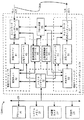
図3は、図1に示すネットワーク10で使用すると便利なスイッチングノード11(n) を示す機能ブロック図である。図3に示すように、スイッチングノード11(n) は、複数の入力ポート60(1) 乃至60(I)(全体を符号60(i) で示している)、複数の出力ポート61(1) 乃至61(I)(全体を符号61(i) で示している)、バッファストア63およびバッファマネージャ64を装備している。各入力ポート60(i) は"CELLS_IN"と名付けたセルを、コンピュータ12(m) またはスイッチングノードから通信リンク13(p) を利用して受信するように接続されている。各出力ポート61(i) は"CELLS_OUT"と名付けたセルを、通信リンク13(p) を利用してコンピュータ12(m) またはスイッチングノードに送信するように接続されている。入力ポート60(i) がスイッチングノードからセルを受信し、出力ポート61(i) がセルをスイッチングノードに送信する場合、スイッチングノード11(n) の入力ポート60(i) がそこからセルを受信し、あるいはスイッチングノード11(n) の出力ポート61(i) がそこへセルを送信するスイッチングノードは、好ましくは、別のスイッチングノード11(n') (n'≠n) になっているが、通信リンク13(p) がスイッチングノード11(n) のループバックコネクションとなっていれば、同一のスイッチングノード11(n) であっても構わない。
【0065】
各入力ポート60(i) は、そこに接続された通信リンク13(p) 上でセルを受信すると、そのセルをバッファストア63に格納する。各入力ポート60(i) は、実際にセルを受信し、それをバッファに格納してからセルがバッファストア63に転送されて、そこに格納されるようにするセルレシーバ70と、入力ポート60(i)がそこでセルを受信する仮想回線に関する仮想回線情報を収めている入力ポートコントロール71とを含んでいる。一実施形態では、セルレシーバ70は、受信したセルのための内部「ダブルバッファ」構成(個別には示されていない)を備えている。具体的には、一方の内部バッファは、バッファストア63に転送される前に受信したばかりのセルの少なくとも一部を収容しておくことができ、その間に、別のセルの一部は他方の内部バッファに受信されている。
【0066】
セルレシーバ70がセルを受信すると、入力ポートコントロール71はそのセルをバッファストア63に転送し、そこにストアしておく。一般的に、バッファストア63は複数の "B" バッファBUF0 乃至BUF(B-1)(全体をBUF(b) で示している)から構成され、これらはバッファマネージャ64内のバッファリンクヘッダ75によってリンクリストに編成されている。バッファBUF(b) の各々は、1つのセルからの情報をストアすることができる。一般的に、バッファストア63とバッファマネージャ64はスイッチングノード11(n) を通る仮想回線ごとに1つのリンクリストを提供し、さらにフリーリストを提供する。他方、バッファリンクヘッダ75は複数のバッファヘッダBUF_HDR(0) 乃至BUF_HDR(B-1)(全体をBUF_HDR(b) で示している)を含み、その各々はバッファストア63内の対応するインデックスをもつBUF(b) と関連付けられている。各入力ポート60(i) の入力ポートコントロール71は仮想回線情報ブロック(個別には示されていない)を維持しており、そこには、特に、ヘッドポインタとテールポインタを含むリンクリストヘッダとバッファカウント値が、入力ポート61(i) がそのパスとなっている仮想回線ごとに、収められている。さらに、バッファマネージャ64は、フリーリストのヘッドポインタとテールポインタを含むフリーリストポインタをもっている。
各リンクリストについて、
【0067】
(i) ヘッドポインタは次を指している。
(a) 仮想回線のリンクリストの場合は、仮想回線のバッファストア63に格納されている第1セルの情報を収めているバッファBUF(b) に関連するバッファヘッダBUF_HDR(b)、または
(b) フリーリストの場合は、フリーリスト内の第1バッファBUF(b) に関連するバッファヘッダBUF_HDR(b)。
【0068】
(ii) テールポインタは次を指している。
【0069】
(a) 仮想回線のリンクリストの場合は、仮想回線のバッファストア63に格納されている最終セルの情報を収めているバッファBUF(b') に関連するバッファヘッダBUF_HDR(b')、または
(b) フリーリストの場合は、フリーリスト内の最終バッファに関連するバッファヘッダBUF_HDR(b)。
【0070】
(iii) バッファカウント値は、仮想回線のリンクリストの場合は、リンクリストにリンクされたバッファストア63内のバッファの数を示している。
以上から理解されるように、ヘッドポイントが指しているバッファBUF(b) はテールポインタが指しているものと同じバッファBUF(b') にすることができるが、そうでなくてもよい。ヘッドポインタが指しているバッファBUF(b) が、テールポインタが指している同じBUF(b') であれば、バッファストア63内のリンクリストに関連するバッファBUF(b) は1つになる。さらに、各バッファヘッダBUF_HDR(b) は、リンクリスト内の最終バッファヘッダを除き、リンクリスト内の次のバッファヘッダBUF_HDR(b") を指している次ポインタを含んでいる。リンクリスト内の最終バッファヘッダ内の次ポインタは、リンクリストのリストヘッダを指していることもあれば、それがリンクリスト内の最終バッファヘッダであることを示している値を含んでいることもある。仮想回線に関連するリンクリストの場合には、バッファBUF(b") は、スイッチングノード11(n) によって受信され、その情報が同じ仮想回線のバッファBUF(b) にストアされているセルの後に続く次のセルの情報をストアしている。
【0071】
一般的に、セルをバッファストア63にストアするとき、入力ポートコントロール71は、フリーリストのヘッドに置かれているバッファヘッダBUF_HDR(b) に関連するバッファBUF(b) にそのセルをストアし、フリーリストヘッダのヘッダポインタとバッファカウントをそれに応じて更新する。さらに、入力ポートコントロール71は、
【0072】
(i) 仮想回線の仮想回線情報ブロック内のバッファカウント値が非ゼロで、アクティブのリンクリストが仮想回線のバッファストア63とバッファマネージャ64にあることを示していれば、仮想回線の仮想回線情報ブロック内に維持されているテールポインタが指しているバッファヘッダの次ポインタを更新し、
【0073】
(ii) セルがストアされているバッファBUF(B) に関連するバッファヘッダBUF_HDR(b) の次ポインタに値をロードし、それがリンクリスト内の最終バッファヘッダであることを示し、
【0074】
(iii) 仮想回線に関連する仮想回線情報ブロックに維持されている、リンクリストヘッダ(必要に応じてヘッドポインタとテールポインタを含んでいる)とセルカウント値を更新する。
各仮想回線に対して入力ポートコントロール71によって維持されている仮想回線情報ブロックは、仮想回線に関連するセルがどの出力ポート61(i') から送信されるのかも示しており、入力ポートコントロール71は、リンクリストを確立したあと、その出力ポート61(i')から送信されるために仮想回線に対してセルが受信されたことも、出力ポート61(i')に通知する。
【0075】
各出力ポート61(i')は、少なくとも1つのセルが、その出力ポート61(i')からセルが送信される仮想回線のバッファストア63に格納されているとの通知を、入力ポート60(i) の入力ポートコントロール71から受信すると、それが接続されている通信リンク13(p)が、クリアされたリンクフロー制御ステートになっていれば、仮想回線に関連するセルをバッファストア63から取り出し、そのセルをそこに接続されている通信リンク13(p) 上に送出するオペレーションを開始する。以上から理解されるように、出力ポート61(i) が接続されている通信リンク13(p) が、セットされたリンクフロー制御ステートになっていれば、出力ポート61(i) は仮想回線に関連するセルを通信リンク上に送信することが禁止される。
【0076】
各出力ポート61(i) は出力ポートコントロール72とセルトランスミッタ73を含んでいる。出力ポートコントロール72は、それぞれの入力ポート60(i) の入力ポートコントロール71から通知を受信する。これに応答して、通信リンク13(p) が、セットされたリンクフロー制御ステートになっていれば、出力ポートコントロール72は、入力ポートコントロール71によって維持されている仮想回線の仮想回線情報ブロックにアクセスしてリンクリストのヘッドポインタを特定し、これによって仮想回線に関連するリンクリスト内の第1セルを特定し、そのセルがバッファストア63から取り出され、セルトランスミッタ73に転送され、その処理および送信が行われるようにする。従来と同じように、セルのヘッダ部分は送信前に更新しておく必要があるが、これはセルトランスミッタによって行われる。セルレシーバ70の場合と同じように、一実施形態では、別のセルの一部がそこに接続された通信リンク13(p) 上に送信される間、セルトランスミッタ73は送信されるセルのための内部「ダブルバッファ」(個別には示されていない)を用意しており、具体的には、一方の内部バッファはバッファストア63から取り出されるセルの一部を収容することができる。セルが送信のために取り出されると、出力ポートコントロール72は入力ポートコントロール71が、セルの取り出しを反映するように、仮想回線の仮想回線情報ブロックに維持されているセルカウントをデクリメントするのを許可することができる。仮想回線情報ブロック内のセルカウント値がデクリメントされたあとゼロになっていなければ、入力ポートコントロール71は、仮想回線のリンクリスクがまだアクティブであることを出力ポートコントロール72に通知する。さらに、入力ポートコントロール71は、仮想回線情報ブロック内のヘッダポインタを、リンクリスト内の次のセルを指すように更新する。出力ポートコントロール72は、バッファストア63に格納されている、それぞれの仮想回線のセルが残っている限り、そこから送信される仮想回線すべてのセルの取り出しを仮想回線ID順のラウンドロビン方式で開始する。
【0077】
以上から理解されるように、入力ポート60(i) はセル以外のメッセージを受信することができる。具体的には、本発明によるセットおよびクリアされた仮想回線フロー制御メッセージと、セットおよびクリアされたリンクフロー制御メッセージを受信することができる。入力ポート60(i) がセットされた仮想回線フロー制御メッセージを受信した場合は、スイッチングノード11(n) はその仮想回線に対してセットされた下流側仮想回線フロー制御ステートに入り、その場合には、入力ポート60(i) に関連する入力ポートコントロール71は、仮想回線に対して維持されている仮想回線情報ブロック内の下流側仮想回線フロー制御ステートフラグ(別個には示されていない)をセットし、さらに、ソースコンピュータ12(mS)、つまり、仮想回線のソースコンピュータ12(mS) に向かう仮想回線のパス上の上流側スイッチングノード11(n") に接続されている該当出力ポート61(i") が、セットされた仮想回線フロー制御メッセージを通信リンク13(p) 上に送信することを許可する。
【0078】
上述したように、スイッチングノード11(n) は、仮想回線に関連するセルが余りに高速レートで受信されるため仮想回線上の下流側に送信できないと判断したときは、セットされた仮想回線フロー制御ステートに入って、セットされた仮想回線フロー制御メッセージを生成し、仮想回線のパス上の下流側にそれを送信することもできる。これに関連して、仮想回線の仮想回線情報ブロックを維持している入力ポート60(i) に関連する入力ポートコントロール71は、ローカル仮想回線フロー制御フラグも維持しており、入力ポートコントロール71はこのフラグをセットすることにより、仮想回線をセットされたローカル仮想回線フロー制御ステートに配置することができる。入力ポートコントロール71がローカル仮想回線フロー制御フラグをセットすると、上流側スイッチングノード11(n") または仮想回線のソースコンピュータ12(mS) に接続された出力ポート60(i") が、セットされた仮想回線フロー制御メッセージを通信リンク13(p) 上に送信するのを許可することもできる。仮想回線に関連するパス上の下流側スイッチングノードまたは仮想回線に関連するデスティネーションコンピュータ12(mD) に接続された出力ポート61(i') は、バッファストア63に置かれている仮想回線に関連するセルを十分な数だけ取り出したあと、ローカル仮想回線フロー制御フラグをクリアして、仮想回線をクリアされたローカル仮想回線フロー制御ステートに置くことができる。
【0079】
下流側仮想回線フロー制御フラグとローカル仮想回線フロー制御フラグは、スイッチングノード11(n) による仮想回線の、クリアされた仮想回線フロー制御メッセージの送信または生成を制御するためにも使用される。これに関連して、
【0080】
(i) 入力ポート60(i) が仮想回線に関連するクリアされた仮想回線フロー制御メッセージを受信した場合は、下流側仮想回線フロー制御フラグをクリアすると、仮想回線をクリアされた下流側仮想回線フロー制御ステートに配置することができ、仮想回線もセットされた仮想回線フロー制御ステートになっていなければ、入力ポート60(i) は、仮想回線に関連するパス上の上流側スイッチングノード、または仮想回線に関連するソースコンピュータ12(mS) に接続された出力ポート60(i") が、クリアされた仮想回線フロー制御メッセージを生成し、送信することを許可することができる。
【0081】
(ii) 仮想回線に関連するパス上の下流側スイッチングノード、または仮想回線に関連するソースコンピュータ12(mS) に接続された出力ポート61(i') がローカル仮想回線フロー制御フラグをクリアし、仮想回線をクリアされたローカル仮想回線フロー制御ステートに配置し、仮想回線もセットされた下流側仮想回線フロー制御ステートになっていなければ、出力ポート61(i') は、仮想回線に関連するパス上の上流側スイッチングノード、または仮想回線に関連するソースコンピュータ12(mS) に接続された出力ポート60(i") が、クリアされた仮想回線フロー制御メッセージを生成し、送信するのを許可することができる。
【0082】
本発明によれば、入力ポート71と出力ポートコントロール72も、特定の仮想回線をセットおよびクリアされたローカル仮想回線フロー制御ステートに配置するべきかどうかの判断に関して、および特定の通信リンク13(p) をセットまたはクリアされたリンクフロー制御ステートに配置するかどうかに関して、いくつかのオペレーションを実行する。最初に、ローカル仮想回線フロー制御ステートに関しては、仮想回線のローカル仮想回線フロー制御ステートをセットするか、クリアするかの判断は、次に基づいて行われる。
【0083】
(i) 仮想回線に関連するパス上の下流側スイッチングノードまたは仮想回線に関連するデスティネーションコンピュータ12(mD) に接続された出力ポート61(i') の出力ポート仮想回線利用数(utilization number)。
【0084】
(ii) バッファストア63のセル占有レベル(cell occupancy level)。
【0085】
(iii) バッファストア63に格納されている、仮想回線に関連するセルの数。
出力ポート61(i')の出力ポート仮想回線利用数は、出力ポート61(i')によって送信されるセルをバッファストア63がストアしている仮想回線の数を示している。上述したように、出力ポート61(i) は仮想回線のセルを仮想回線ID順のラウンドロビン方式で取り出すために、特定の出力ポート61(i')の出力ポート仮想回線利用数が増加すると、特定の仮想回線の取り出しと取り出しの間の時間が増加するので、バッファストア63のセル占有レベル(上記項目(ii))が増加し、特定の仮想回線に関連するセルの数(上記項目(iii))も増加すると、望ましくない輻輳が発生することになる。
【0086】
一実施形態では、出力ポートコントロール72は、各出力ポート61(i) に対して3つの出力ポート仮想回線利用レベル(上記項目(i)参照)、すなわち、低利用レベル、通常利用レベル、高利用レベルを定義している。出力ポート61(i) によって送信されるセルをバッファストア63がストアしている仮想回線の数が、
(a) 選択した低出力ポート利用しきい値以下であれば、出力ポートコントロール72は、出力ポート61(i) が低利用レベルにあると判断する。
(b) 選択した低出力ポート利用しきい値と選択した高出力ポート利用しきい値の間にあれば、出力ポートコントロール72は、出力ポート61(i) が通常利用レベルにあると判断する。
【0087】
(c) 高出力ポート利用しきい値を越えていれば、出力ポートコントロール72は、出力ポートが高利用レベルにあると判断する。
さらに、出力ポートコントロールは、1つのバッファ占有しきい値(上記項目(ii) 参照)と、3セットのバッファ格納セル「ウォータマーク(watermark)」レベル(上記項目(iii)参照)を定義している。各セットのバッファ格納セルウォータマークレベルは、バッファストア63に格納されている、仮想回線に関連するセルがある数に達すると、仮想回線がセットされたローカル仮想回線フロー制御ステートに配置されることを示し、バッファ格納セル数がある数に達すると、仮想回線がクリアされたローカル仮想回線フロー制御ステートに配置されることを示している。バッファ格納セルウォータマークのセットは、低バッファ格納セルウォータマークレベル、中間バッファ格納セルウォータマークレベル、および高バッファ格納セルウォータマークレベルを含んでおり、これらは、その数に達すると仮想回線がセットされたローカル仮想回線フロー制御ステートに配置され、その数に達すると仮想回線がクリアされたローカル仮想回線フロー制御ステートに格納される、仮想回線に関連する両方のバッファ格納セル数が、連続的に大きくなることを定義している。
【0088】
入力ポートコントロール71は出力ポート仮想回線利用レベルとバッファ占有レベルを使用して、バッファ格納セルウォータマークのセットの1つを選択し、これは仮想回線をセットまたはクリアされた仮想回線フロー制御ステートに配置するべきかどうかを判断するために使用される。これに関連して、バッファストア63のセル占有レベルが、各仮想回線についてバッファ占有しきい値以下であると出力ポートコントロール72が判断したとき、
【0089】
(i) 仮想回線に関連するセルを送信のために取り出す出力ポート61(i') に関連する仮想回線利用レベルが低利用レベルにあれば、入力ポートコントロール71は高バッファ格納セルウォータマークレベルのセットを選択する。
【0090】
(ii) 仮想回線に関連するセルを送信のために取り出す出力ポート61(i') に関連する仮想回線利用レベルが中間利用レベルにあれば、入力ポートコントロール71は中間バッファ格納セルウォータマークレベルのセットを選択する。
【0091】
(iii) 仮想回線に関連するセルを送信のために取り出す出力ポート61(i') に関連する仮想回線利用レベルが高利用レベルにあれば、入力ポートコントロール71は低バッファ格納セルウォータマークレベルのセットを選択する。
他方、バッファストア63のセル占有レベルが、各仮想回線についてバッファ占有しきい値にあるか、あるいはそれを越えていると入力ポートコントロール71が判断したとき、
【0092】
(iv) 仮想回線に関連するセルを送信のために取り出す出力ポート61(i') に関連する仮想回線利用レベルが低利用レベルにあれば、入力ポートコントロール71は中間バッファ格納セルウォータマークレベルのセットを選択する。
【0093】
(v) 仮想回線に関連するセルを送信のために取り出す出力ポート61(i') に関連する仮想回線利用レベルが中間利用レベルにあれば、入力ポートコントロール71は低バッファ格納セルウォータマークレベルのセットを選択する。
【0094】
(vi) 仮想回線に関連するセルを送信のために取り出す出力ポート61(i') に関連する仮想回線利用レベルが高利用レベルにあれば、この場合も、入力ポートコントロール71は低バッファ格納セルウォータマークレベルのセットを選択する。
【0095】
以上から理解されるように、仮想回線利用レベルが増加すると共に、仮想回線をセットされた仮想回線フロー制御ステートに配置するために必要とされる、仮想回線に関連するバッファ格納セルの数は少なくなる。しかし、バッファストア63のバッファ占有レベルが増加してバッファ占有しきい値を越えると、バッファ格納セルウォータマークレベルが選択されるので、仮想回線をセットされた仮想回線フロー制御ステートに配置するために必要とされる、仮想回線に関連するバッファ格納セルの数は少なくなる。入力ポートコントロール71は各仮想回線に対して選択されたバッファ格納セルウォータマークレベルセットの中のウォータマークレベルを使用して、仮想回線をセットまたはクリアされたローカル仮想回線フロー制御ステートに配置するために、ローカル仮想回線フロー制御フラグをセットするか、クリアするかを判断する。
【0096】
一実施形態では、各バッファ格納セルウォータマークレベルセット内で、その数に達すると、仮想回線がクリアされたローカル仮想回線フロー制御ステートに配置される、バッファストア63に格納されているセルの数を識別するバッファ格納セルウォータマークレベルは、その数に達すると、仮想回線がセットされたローカル仮想回線フロー制御ステートに配置される、バッファストア63に格納されているセルの数を示しているバッファ格納セルウォータマークレベルよりも低くなっている。このようにすると、ある程度の「ヒステリシス」が得られるので、特定の仮想回線に関連するバッファストア63に格納されているセルの数が該当ウォータマークレベルに近づいたときセルがスイッチングノード11(n) によって取り出されて、送信される場合、特定の仮想回線に関連するローカル仮想回線フロー制御ステートが、セットされたステートとクリアされたステートの間で急激に切り替わることが有効に防止されることになる。
【0097】
さらに、入力ポートコントロール71は、スイッチングノード11(n) またはそこに接続された特定の通信リンク13(p) を、セットまたはクリアされたリンクフロー制御ステートにいつ移行させるかを判断し、その判断に応じて出力ポート61(i) によるリンクフロー制御メッセージの送信を制御する。一般的に、入力ポート60(i) の入力ポートコントロール71は、
【0098】
(i) バッファストア63のセル占有レベルが、選択したセットされたリンクフロー制御しきいレベルを超えるレベルに増加したときは、スイッチングノード11(n) に接続された通信リンク13(p) をセットされたリンクフロー制御ステートに配置し、その場合には、入力ポートコントロール71は対応するインデックスをもつ出力ポート61(i) が、セットされたリンクフロー制御メッセージを送信することを許可し、そのあと、
【0099】
(ii) スイッチングノード11(n) をクリアされたリンクフロー制御ステートに配置し、
(a) バッファストア63のセル占有レベルが選択した、クリアされたリンクフロー制御しきいレベル以下のレベルに減少したときは、通信リンク13(p) をクリアされたリンクフロー制御ステートに配置し、その場合には、入力ポートコントロール71は、対応するインデックスをもつ出力ポート61(i) が、クリアされたリンクフロー制御メッセージをスイッチングノード11(n) またはそこに接続されたコンピュータ12(m) に送信することを許可し、あるいは
(b) 仮想回線に関連付けられていて、それぞれの入力ポート60(i) から受信されたバッファストア63に格納されているセルの数があらかじめ決めた入力ポートごとのしきいレベルに等しいか、または低いときは、入力ポート60(i) に接続された通信リンク13(p) をクリアされたリンクフロー制御ステートに配置し、その場合には、入力ポート60(i) の入力ポートコントロール71は、対応するインデックスをもつ出力ポート61(i) がスイッチングノード11(n) またはそこに接続されたコンピュータ12(m) にクリアされたリンクフロー制御メッセージを送信することを許可する。一実施形態では、入力ポートごとのしきいレベルはゼロになるように選択されている。
一実施形態では、セットされたリンクフロー制御しきいレベルは、クリアされたリンクフロー制御しきいレベルよりも大になっている。このようにすると、ある程度の「ヒステリシス」が得られるので、特定の仮想回線に関連するバッファストア63に格納されているセルの数がセットされたリンクフロー制御しきいレベルに近づいたときセルがスイッチングノード11(n) によって受信され、送信される場合、リンクフロー制御ステートが、セットされたステートとクリアされたステートの間で急激に切り替わることが有効に防止されることになる。
【0100】
バッファリンクヘッダ75のほかに、バッファマネージャはアービタ76も含んでおり、このアービタ76は、入力ポートコントロール71と出力ポートコントロール72によるバッファストア63へのアクセス、バッファマネージャ64によって維持されているバッファリンクヘッダ75へのアクセス、および入力ポート61(i) の各々の入力ポートコントロール71によって維持されている仮想回線情報へのアクセスをスケジュールする。一般的に、
【0101】
(i) 入力ポート60(i) の入力ポートコントロール71は、仮想回線に関連するセルを受信するとき、次のものにアクセスする必要がある。
(a) バッファストア63内のどのバッファBUF(b) にセルをストアしようとしているのかを識別するために、およびフリーリストのリンクリスト情報を更新するためにフリーリストについて、バッファマネージャ64によって維持されているリンクリスト情報、
(b) 示されたバッファに受信セルをストアするためにバッファストア63、
(c) そこからリンクリスト情報を取り出し、そのリンクリスト情報、セルカウント値および仮想回線のフロー制御ステータスを更新するために、さらに、どの出力ポート61(i) からセルが送信されるかを示すために、入力ポートコントロール71によって維持されている仮想回線情報ブロック、および
(d) 受信セルがストアされたバッファをフロー制御のリンクリストにリンクするために、入力ポートコントロール71によって維持されている仮想回線情報ブロック内のリンクリスト情報によって示されている、仮想回線に関連するリンクリストについてバッファマネージャによって維持されているリンクリスト情報。
【0102】
(ii) 出力ポート61(i) の出力ポートコントロール72は、仮想回線に関連するセルを送信しようとするとき、次のものにアクセスする必要がある。
(a) リンクリスト情報を取り出し、リンクリスト情報とセルカウント値を含む情報を更新するために、さらに、仮想回線のフロー制御ステータスを必要に応じて更新するために、そこからセルが受信された仮想入力ポートコントロール71によって維持されている仮想回線情報、
(b) バッファから送信するためのセルを取り出すために、バッファストア63、および
(c) 仮想回線のリンクリストからセルが送信されるバッファをデリンク(de-link)し、バッファをフリーリストにリンクするために、バッファマネージャによって維持されているリンクリスト情報。
【0103】
一般的に、アービタ76は、入力ポート61(i) の入力ポートコントロール71と出力ポート61(i) の出力ポートコントロール72によるアクセス要求の仲裁を行う。このオペレーションでは、一実施形態によれば、アービタ76は、一般的に入力ポートコントロール71相互間にラウンドロビン方式で高い優先度をもたせ、出力ポートコントロール72相互間にラウンドロビン方式で低い優先度をもたせるようにしている。
【0104】
本発明によれば、いくつかの利点が得られる。上述したように、本発明は、コンピュータと他のデバイス間でメッセージをネットワーク上に効率よく転送すると共に、ネットワークの輻輳が原因で起こるセル損失を防止する構成を提供している。ネットワークインタフェース24の送信セクション31によるデータ伝送は、コンピュータ12(m) がそのソースとなっている仮想回線間で、仮想回線ID順のラウンドロビン方式で行われるので、本発明によれば、そこから延長された仮想回線間でかなりの公平性が得られ、仮想回線すべてに少なくとも一部のメッセージ転送バンド幅を効果的に保証し、仮想回線間のメッセージ転送レイテンシを制限するので、決定的なメッセージ転送レイテンシ特性が得られるようにしている。仮想回線間の公平性は、スイッチングノードが、仮想回線に対してそこで受信したセルからのデータを、仮想回線ID順のラウンドロビン方式で転送し、各デスティネーションコンピュータ側では、ネットワークインタフェースの受信セクション31が、コンピュータ12(m) がそのデスティネーションとなっている仮想回線上でそこで受信したセルからのデータを、仮想回線ID順のラウンドロビン方式でシステムメモリ21に転送し、受信バッファ41がいずれかの仮想回線からのデータで過負荷状態になる可能性を低減することによって、さらに向上されている。本発明によれば、スイッチングノード11(n)、具体的には、バッファストア63で使用されるメモリ量を低減化でき、望ましいメッセージ転送飽和特性が得られるので、システムコストを低減化することができる。
【0105】
上述したように、本発明によれば、「エンドツーエンド」仮想回線とリンクフロー制御のメカニズムが効率化されているので、ネットワークの輻輳が原因で起こるセル損失がされに防止される。仮想回線フロー制御に関しては、本発明によれば、それぞれのデスティネーションコンピュータとソースコンピュータ12(m) 間の仮想回線を利用したセルの伝送を、仮想回線が仮想回線のセルを転送し、デスティネーションコンピュータが仮想回線を利用してセルを受信するパスを形成しているスイッチングノードの瞬時容量に基づいて制御するようにメカニズムが効率化されている。さらに、リンクフロー制御に関しては、本発明によれば、各通信リンク上のセルの伝送を、それぞれのリンクを利用してセルを受信するデバイスの瞬時容量に基づいて制御し、それぞれのリンクを利用してセルを受信するメカニズムが別になっている。仮想回線フロー制御は、仮想回線フロー制御が実現されているしきいレベルが、仮想回線のそれぞれを利用した転送レートが大きくなって、セルが転送される他の仮想回線が利用できるバンド幅が不当に制限されることがないように選択されているので、仮想回線間の公平性をさらに向上している。
【0106】
以上から理解されるように、上述してきたシステム10、コンピュータ12(m)およびスイッチングノード11(n) は種々態様に変更することが可能である。例えば、以上から理解されるように、本発明によるシステム10は、スイッチングノード11(n) がなくても、複数のコンピュータ12(m) を相互接続することにより、例えば、2つのコンピュータ12(m) のネットワークインタフェース24を相互接続し、これらが相互間でデータを転送するための仮想回線を確立できるようにすることによって構築することができる。さらに、以上から理解されるように、ゲートウェイ、ブリッジなどの他のタイプのコンピュータでネットワーク10を他のネットワークに接続し、大容量記憶システムなどの、他のタイプのデバイスを、コンピュータ12(m) について上述したのと同じように、メッセージのソースおよび/またはデスティネーションなどのネットワークに接続することも可能である。
【0107】
さらに、システム10は、仮想回線間の優先度を1つとしてメッセージを転送するものとして説明してきたが、以上から理解されるように、システム10は種々の優先度レベルを取り入れることが可能である。従って、例えば、タスクが実行される各仮想回線が識別されてから1つの仮想回線が識別されるようにする、ラウンドロビン方式によるのでは、ある仮想回線を特定する回数を他の仮想回線よりも多くして、これらの仮想回線(つまり、何度も識別される仮想回線)に高い優先度をもたせることが可能である。事実、仮想回線を特定する回数を多くすると、優先度レベルを複数にすることができる。
【0108】
さらに、システム10は、一方では、新規の仮想回線とリンクフロー制御技法を含み、他方では新規のスケジューリング技法を含むものとして説明してきたが、以上から理解されるように、本発明によるシステムは、どの技法を取り入れることも可能であり、上述してきた利点の少なくともいくつかを得ることができる。
【0109】
上述してきたシステム10では、ラウンドロビンスケジューリング技法を利用して、それぞれの受信スケジューラと送信スケジューラ43および53が、どの仮想回線に対してタスクを実行するかを、仮想回線ID順のラウンドロビン方式で特定するようにようしているが、以上から理解されるように、他のラウンドロビンID方式を使用することも可能である。例えば、それぞれのタスクで種々の仮想回線IDリストを使用することが可能であり、タスクが特定の仮想回線で可能にされたとき、仮想回線のIDをリストの終わりに付加することができる。この場合には、それぞれのスケジューラは、連続するエントリからの仮想回線を、リストの先頭から特定していくことができる。以上から理解されるように、ラウンドロビン技法をスケジューラ43および53で使用すると、ハードウェア設計が単純化されるが、仮想回線は、そのビットがそれぞれのメモリにセットされた直後にだけ、タスク処理のために特定されることになり、このことは仮想回線間の公平性を若干損なうことになる。他方、仮想回線IDリストは、タスクが可能にされる順に仮想回線に対してタスクが実行される可能性を大にするので、仮想回線間の公平性が増加するが、ハードウェア設計は若干複雑化する。
【0110】
さらに、ATMセルを使用したデータ転送に関して本発明を説明してきたが、以上から理解されるように、他のデータ転送技法を使用することも可能である。
【0111】
以上から理解されるように、本発明によるシステムは、その全体または一部を特殊目的コンピュータまたは汎用コンピュータ、あるいはその組み合わせで構築することが可能であり、その一部は適当なプログラムで制御することができる。どのプログラムも、その全体または一部をシステムの一部にすることも、適当な方法でシステム上に格納しておくことも可能であり、あるいはその全体または一部をネットワークまたは適当な方法で情報を転送する他のメカニズムを利用して、システムに送るようにすることも可能である。さらに、以上から理解されるように、システムは、システムに直接に接続されているか、あるいはネットワークまたは適当な方法で情報を転送する他のメカニズムを利用して情報をシステムに送ることができるオペレータ入力エレメント(図示せず)を使用するオペレータから与えられた情報によって操作し、および/または他の方法で制御することができる。
【0112】
上述してきた説明は本発明の特定の実施形態に限定されるが、以上から理解されるように、本発明を種々態様に変更または改良することにより、本発明の利点のすべてまたは一部を達成することができる。上記実施形態およびその変形または改良形態は請求項の対象になっており、これらは本発明の真の精神と範囲に属するものである。
【図面の簡単な説明】
本発明は具体的には特許請求の範囲に記載されているが、本発明の上記および他の利点を理解しやすくするために、以下では、添付図面を参照して説明することにする。
【図1】 本発明によるフロー制御構成が実装されているコンピュータネットワークを示す概略図である。
【図2】 図1に示すコンピュータネットワークで使用されるコンピュータシステムを示す機能ブロック図である。
【図3】 図1に示すコンピュータネットワークで使用されるスイッチングノードを示す機能ブロック図である。
【図4】 本発明によるコンピュータシステムのオペレーションを示す詳細フローチャートである。
【図4A】 本発明によるコンピュータシステムのオペレーションを示す詳細フローチャートである。
【図5】 図2に示すコンピュータネットワークで使用される受信スケジューラを示す機能ブロック図である。
【図6】 図2に示すコンピュータネットワークで使用される送信スケジューラを示す機能ブロック図である。[0001]
Field of Invention
The present invention relates generally to the field of digital communication systems, and more particularly to facilitate communication of digital data and communication between digital computer systems, for example in digital image, audio and video distribution systems. Related to digital networks. More specifically, the present invention provides a flow of information through the network to prevent congestion, prevent data loss, and maintain fairness among multiple devices that transfer information using the network. ) For flow control and scheduling configuration.
[0002]
Background of the Invention
Digital networks have already been developed that facilitate the transfer of information, including data and programs, between digital computer systems and other digital devices. Different types of networks have been developed and built using different information transfer techniques. In some networks, such as the well-known Ethernet, a single wire is used to interconnect all of the devices connected to the network. This method simplifies the wiring of the network in the facility and simplifies connecting devices to the network, but the wire can only convey information in the form of messages from one device at a time. Information transfer is generally slow. To alleviate this problem to some extent, in some Ethernet installations, the network is divided into several sub-networks, each sub-network has a separate wire, and these wires are interconnected by an interface. Yes. In such facilities, the number of messages that can be transferred at the same time is increasing because the wire can simultaneously transmit the messages of the devices connected to it. Wires in two or more subnetworks are used only when a device connected to one wire needs to send a message to a device connected to another wire The other devices that are used cannot use the subnetwork.
[0003]
In order to further alleviate this problem, a network in which communication (communication) is processed through a mesh-like switching node has been developed. Computer systems and other devices are connected to various switching nodes. Because switching nodes themselves are interconnected in various patterns, multiple paths are available between a pair of devices, so that when one path is congested, another path can be used. ing. In such a configuration, the network is more complicated than the Ethernet network, but the information transfer rate must be significantly increased, especially when optical fibers are used as the medium for interconnecting switching nodes and devices. It is possible. This type of network has the following problems: That is, in this type of network, a mechanism that provides "flow-control" information to the sending switching node or device when the switching node or device receives information from another switching node or device in the network. There is no. This will certainly reduce the cost of the network, but it will cause congestion, and when congestion occurs, the switching node will receive information at a higher rate than the transmission capability, or the destination. The device is supposed to store information in a buffer and receive information at a rate faster than it can process the information.
[0004]
Summary of the Invention
The present invention seeks to provide a new and improved system and method for scheduling message transfers in a communication network.
[0005]
Briefly and briefly described, according to one embodiment of the present invention, a system is provided that includes at least two devices interconnected by a network that includes at least one communication link. Each device is equipped with a network interface for transferring messages using the network. At least one of these devices, as a source device, sends a message using one or more virtual circuits established on the network, and at least one of the other said devices. One receives a message using a virtual circuit as a destination device of each virtual circuit. The destination device network interface includes a receive section that includes a buffer configured to buffer messages received on all virtual circuits on which the device is a destination device, and a destination flow. And a control circuit. The destination flow control circuit: (i) when the portion of the buffer occupied by a message received on one virtual circuit exceeds the selected virtual circuit flow control threshold level, the device Generate a virtual circuit flow control message associated with the virtual circuit that is the device and forward it over the communication link to the source device for that virtual circuit, and (ii) the portion of the buffer occupied by the message is selected When the link flow control threshold level is exceeded, a link flow control message is generated and transmitted on the communication link. The network interface of the source device includes a transmission section configured to transmit a message over one or more virtual circuits for which it is a source device, and a source flow control circuit. A source flow control circuit, (i) when a virtual circuit flow control message associated with a virtual circuit is received by the source device, in response, the transmission section prohibits sending a message on the virtual circuit; (ii) When a link flow control message is received by the source device on the communication link connected to it, in response, the sending section is prohibited from sending messages on the communication link. . Therefore, the destination device sends a virtual circuit flow control message to the virtual circuit when the buffer occupancy by the virtual circuit exceeds the virtual circuit flow control threshold level. The amount of buffer resources occupied by is limited so that the fairness of buffer resources can be kept valid among all virtual circuits. In addition, the destination device transmits a link flow control message to prevent buffer overflow that causes message loss.
[0006]
In another embodiment, the network includes a switching node that forms part of a path for one or more virtual circuits between the source device and the destination device. A switching node receives a message sent from a source device using its virtual circuit that forms part of a path on a communication link to which the node is connected, and receives the received message in an internal buffer Is stored (buffered), and the message stored in the buffer is transmitted using the virtual circuit on another communication link connected thereto, and the message for the virtual circuit is transmitted to the virtual circuit. The data is transferred to each downstream side on the line. When a switching node receives a virtual circuit flow control message for a virtual circuit on a communication link that is to send a message on that virtual circuit, the switching node must receive the message for the virtual circuit there The virtual circuit flow control message is transferred to the upstream side of the virtual circuit by transferring the virtual circuit flow control message to the communication link. If a switching node receives a link flow control message on a communication link, the switching node stops sending messages on the communication link. In addition, if the switching node buffer occupancy due to a message from a particular virtual circuit exceeds the selected virtual circuit threshold level (which in one embodiment, the switching node The switching node generates a virtual circuit flow control message on the communication link on which the switching node is to receive messages for that virtual circuit. And the virtual circuit flow control message is forwarded upstream on the virtual circuit, thereby prohibiting the source device for that virtual circuit from transmitting a message on the virtual circuit. When the switching node's buffer occupancy exceeds the selected link threshold level, the switching node generates a link flow control message and is connected to the switching node on which the switching node receives the message. Send the message to. Therefore, when the buffer occupancy by the virtual circuit exceeds the virtual circuit flow control threshold level, the switching node sends a virtual circuit flow control message to the virtual circuit, thereby sending a message related to one of the virtual circuits. The amount of buffer resources to be occupied is limited so that the fairness of the buffer resources is kept valid among all virtual circuits. Further, the switching node transmits a link flow control message to prevent buffer overflow that causes message loss.
[0007]
Detailed description of embodiments
FIG. 1 shows a
[0008]
In one embodiment, data is transferred using the well-known “ATM” (“Asynchronous Transfer Mode”) transfer technique. This technique is mainly described in
[0009]
In the present invention, the computer 12 (m) and the switching node 11 (n) control the flow of cells on the network to prevent or reduce congestion on both the switching node 11 (n) side and the destination computer side. Provides a configuration to do this. Without such a configuration, cell transfer throughput may be reduced or cells may be lost on the network. In addition, the present invention ensures that the fairness of information transfer is maintained globally by scheduling operations by the computer 12 (m) and the switching node 11 (n), and the various established through the
[0010]
Each switching node 11 (n) on the virtual circuit path may receive a cell related to the virtual circuit at a too high rate, for example, and may not be transferred downstream on the virtual circuit path. When operating in the virtual circuit flow control mode, enter the set virtual circuit flow control state, generate a set virtual circuit flow control message, and upstream on the path of the virtual circuit Can send the message.Destination computer (m D From)Source computer 12 (m S ) Upstream switching node 11 (n) on the virtual circuit path to (if any)IsIt operates in the same way as described above.
[0011]
Destination computer 12 (mD) Will be able to resume cell reception for that virtual circuit, it will enter the cleared virtual circuit flow control state, so it generates a cleared virtual circuit flow control message and goes upstream on the path of that virtual circuit. Transmit the message. When the switching node 11 (n) receives the cleared virtual circuit flow control message, if it is not in the set virtual circuit flow control state, the set virtual circuit flow control message is transmitted to the virtual circuit path control message. The data is transmitted upstream to the upstream switching node 11 (n) (if present) on the path leading to the source computer 12 (mS), or the virtual line source computer 12 (mS). On the other hand, when the switching node 11 (n) receives the cleared virtual circuit flow control message, if it is in the set virtual circuit flow control state, the transfer of the cleared virtual circuit flow control message is set. The virtual circuit flow control message is postponed until exiting from the virtual circuit flow control state, and when this state is exited, the cleared virtual circuit flow control message is transferred to the upstream side on the virtual circuit path. Source computer 12 (mS) Receives the cleared virtual circuit flow control message, it is possible to resume transmitting the cell associated with the virtual circuit downstream on the virtual circuit. As can be understood from the above description, the switching of the cleared virtual circuit flow control message to the downstream side of the virtual circuit path is postponed while the switching node 11 (n) is in the set virtual circuit flow control state. If possible, the switching node 11 (n) is connected to the upstream switching node 11 (n) or the source computer 12 (mS) Can transfer virtual circuit cells before it can resume transmitting cells there, reducing the number of cells that need to be buffered for virtual circuits It will be.
[0012]
The link flow control mode is realized not in units of virtual circuits but in units of communication links. Therefore, in the link flow control mode, if the computer 12 (m) is receiving a cell from the switching node 11 (n) connected to the computer 12 (m) at a too high rate, it cannot be processed. Since the computer 12 (m) operating in the link flow control mode enters the set link flow control state, the flow control of the communication link becomes possible. In this operation, the computer 12 (m) generates a set link flow control message and transmits the message to the switching node 11 (n) connected thereto using the link. When the switching node 11 (n) receives the set link flow control message, the switching node 11 (n) stops using the link to transmit a cell thereto. Similarly, each switching node 11 (n) is set when operating in the link flow control mode, for example, when cells are received at a too high rate and cannot be transferred (also described below). Enter the designated link flow control state, generate each set link flow control message, and connect to other switching node 11 (n) or to the computer 12 ( Send these messages to m). When the switching node 11 (n) or the computer 12 (m) receives the set link flow control message, the cell is sent to the switching node 11 (n) to which each set link flow control message is sent. Stop sending.
[0013]
When the computer 12 (m) can resume receiving cells from the switching node 11 (n) using the communication link 13 (p), it enters the cleared link flow control state and clears the cleared link. A flow control message is generated, and the message is transmitted to the switching node 11 (n). When switching node 11 (n) receives the cleared link flow control message, it can resume sending cells to computer 12 (m). Similarly, when switching node 11 (n) operating in the set link flow control state can resume receiving cells, it enters the cleared link flow control state and each cleared A link flow control message can be generated and sent to the switching node 11 (n) and / or the computer 12 (m) connected thereto. In either case, when the switching node 11 (n) and the computer 12 (m) receive the cleared link flow control message, the switching node 11 (n) from which the cleared link flow control message has been sent. Alternatively, transmission of the cell to the computer 12 (m) can be resumed.
[0014]
Several advantages are obtained when the virtual circuit flow control mode and the link flow control mode are separate. For example, when the virtual circuit flow control mode is used, each destination computer 12 (mD) And the virtual circuit where each switching node 11 (n) is a part of the path, the fairness of the cell transmission bandwidth through the network is generally maintained. Get drunk. The use of the virtual circuit flow control mode can also reduce the possibility of excessive congestion. On the other hand, using the link flow control mode, when excessive congestion has actually occurred, the cells stored in the computer 12 (m) at a rate that causes the buffer stored therein to overflow and thus cause the cells to be lost. Or the possibility of being received by the switching node 11 (n) is prevented or at least reduced. In one embodiment, the various flow control messages, i.e., the set and cleared virtual circuit flow control messages and the set and cleared link flow control messages are relatively short messages that include message Type, that is, a set virtual circuit flow control message, a cleared virtual circuit flow control message, a set link flow control message, or a cleared link flow control message, A message type flag indicating ID and an ID part are included. When the ID portion is a predetermined value, ie, “zero” in one embodiment, the message is a link flow control message that is set or cleared depending on the value of the message type flag. On the other hand, when the ID part is a value different from the predetermined value, the message is also a virtual circuit flow control message that is set or cleared according to the value of the message type flag. The value indicates which virtual circuit the message is associated with. Since the virtual circuit and link flow control messages set and cleared are relatively short, only a small amount of bandwidth through the network is sufficient to forward the message.
[0015]
Before describing the flow control configuration used in
[0016]
(i) Computer 12 (m) is a source computer 12 (mS), The processor sets a buffer (not shown separately) in the system memory 21 and the destination computer 12 (mDThe data block to be transferred to another computer can be loaded there.
[0017]
(ii) The computer 12 (m) is connected to the destination computer 12 (mD), The processor sets a buffer (also not shown separately) in the system memory and the source computer 12 (mSData blocks received from other computers can be stored there. As described, this embodiment is described in Virtual Interface Architecture VIA Standard Version 1 (December 16, 1997) (issued by Compaq Computer Corp., Intel Corp, and Microsoft Corp). Yes.
[0018]
The mass storage subsystem can typically store information that can be processed by the
[0019]
The input /
[0020]
The network interface 24 is connected to the destination computer 12 (mDThe data to be transferred to another computer operating as) is taken out of the system memory 21, and a cell is generated therefrom, and the generated cell is transferred using the communication link 13 (p). Further, the network interface 24 receives a cell from the communication link 13 (p), extracts data from the cell, transfers the data to a corresponding buffer in the system memory 21, and stores it therein. The network interface 24 includes a plurality of components, including a reception section 30, a transmission section 31, a system interface circuit 32, and a
[0021]
As described above, the receiving section 30 receives cells from the communication link 13 (p) connected to the computer 12 (m), stores the data from the received cells in a buffer, and cooperates with the system interface circuit 32. Then, the data stored in the buffer is transferred to the system memory 21 and stored therein. The reception section includes several components, including a network reception interface circuit 40, a reception buffer 41, a
[0022]
The reception virtual circuit control circuit 44 stores information of each virtual circuit through which the cell is sent to the network interface 24. Such information includes, for each virtual circuit, a pointer that points to a location in the system memory 21 that stores the transmitted data, the virtual circuit, and the virtual circuit, and that data is currently If there is a linked list associated with the number of cells in the buffer indicating the number of received cells stored in the receive buffer 41, a pointer to its head and tail location is included. While the reception buffer 41 does not store any data from a cell related to a specific virtual circuit, the reception virtual circuit control circuit 44 indicates that there is no link list in the virtual circuit. While there is data from at least one related cell, the reception virtual circuit control circuit 44 stores link list information of the virtual circuit. As understood from the above, when the reception buffer 41 stores data from only one cell related to a specific virtual circuit, the head pointer and the tail pointer point to the same location. That is, it indicates the location in the reception buffer 41 that stores the data. When the data from the reception cell is in the network reception interface circuit 40 and the data is stored in the reception buffer 41, the network reception interface circuit 40 uses the information in the reception virtual circuit control circuit 44, It can be determined whether or not a link list exists in the virtual circuit. When the reception virtual circuit control circuit 44 indicates that the link list does not exist in the virtual circuit, the network reception interface circuit 40 sets a pointer indicating the location in the reception buffer 41 where the data from the cell is stored, It is possible to load the received virtual circuit control circuit 44 as both the head and tail pointers of the link list and increment the value of the number of cells in the buffer. Under this condition, the value of the number of cells in the buffer is “1”. On the other hand, if the reception virtual circuit control circuit 44 indicates that the link list exists, the network reception interface circuit 40 links the data just stored to the tail of the link list associated with the virtual circuit, and Is associated with the receiving cell. In addition, the network receive interface circuit 40 updates the tail pointer in the receive virtual circuit control circuit 44 to point to the location of the data just stored as the new tail of the linked list.
[0023]
The
[0024]
The
[0025]
As described above, the transmission section 31 cooperates with the system interface circuit 32 to retrieve data transmitted from the system memory 21 using the interconnection configuration 25, generate a cell, and connect the cell to the communication link 13 (p ) Transmit above. The transmission section 31 includes several components, including a
[0026]
The sending
[0027]
The network transmission interface circuit 52 extracts data from the transmission buffer 51, generates a cell named "CELLS OUT" from the data, and transmits it using the communication link 13 (p) connected to the computer 12 (m). . In this operation, when the network transmission interface circuit 52 retrieves data related to a specific virtual circuit from the transmission buffer 51, the data is extracted from the head of the link list related to the virtual circuit. Link list information stored in the virtual circuit control circuit 54, specifically, a head pointer is used. After the network transmission interface circuit 52 retrieves the data from the transmission buffer 51 associated with the cell from the head of the link list associated with the virtual circuit of the cell, the network transmission interface circuit 52 is maintained by the transmission virtual circuit control circuit 54. If the next location where data is stored for the virtual circuit is in the receive buffer 41 of the link list, the head pointer of the virtual circuit being updated is updated to point to that location, and the number of cells in the virtual circuit buffer is updated. Decrement the value. If the data just extracted is the last data of the virtual circuit, the network transmission interface circuit 52 decrements the value of the number of cells in the buffer to zero so that the link list related to the virtual circuit does not exist in the transmission buffer 51. Can be shown.
[0028]
The
[0029]
According to one aspect of the invention, the
[0030]
(i) Control the transmission rate of the cell by the transmission section 31.
[0031]
(ii) The transmission section can transmit the virtual circuit flow control message and the link flow control message using the communication link 13 (p) as necessary.
[0032]
Regarding the above (i), the
(a) After receiving the set virtual circuit flow control message, the transmission section 31 is prohibited from transmitting a cell related to a specific virtual circuit until a cleared virtual circuit flow control message is received. After receiving the set virtual circuit flow control message, the
[0033]
(b) After receiving the set link flow control message, the network transmission interface 52 is prohibited from transmitting cells using the communication link 13 (p) until the cleared link flow control message is received. .
[0034]
With respect to the above (ii), the
(a) When operating in the non-flow control state, the network transmission interface circuit 52 is prohibited from transmitting a set virtual circuit or link flow control message, and is set in a round-robin manner in the order of virtual circuit IDs. The virtual circuit in the virtual circuit flow control state thus set is put into the cleared virtual circuit flow control state, and the network transmission interface circuit 52 can transmit the virtual circuit flow control message cleared for that purpose.
[0035]
(b) When operating in normal congestion state,
(I) For each virtual circuit whose receive buffer occupancy level for each virtual circuit is greater than or equal to the total receive buffer flow control threshold value for each selected virtual circuit, the virtual circuit is set to the set virtual circuit flow control state and the network Allows transmit interface circuit 52 to transmit the virtual circuit flow control message set for it. But,
(II) For virtual circuits that are in the set virtual circuit flow control state but whose receive buffer occupation level for each virtual circuit is less than or equal to the receive buffer flow control threshold value for each selected virtual circuit, the virtual circuit ID order In the round robin method, the virtual circuit is set to the cleared virtual circuit flow control state, and the network transmission interface circuit 52 can transmit the cleared virtual circuit flow control message.
[0036]
(c) When operating in the middle congestion state, each virtual circuit when the receiving section receives a cell is put into the set virtual circuit flow control mode, and the network transmission interface circuit 52 is set for this purpose. Allows sending flow control messages.
[0037]
(d) When operating in a high congestion state, it enables the network transmission interface circuit 52 to transmit the link flow control message set for it.
When the
[0038]
The operations performed by the
[0039]
On the other hand, if the
[0040]
On the other hand, when the
[0041]
Returning to step 104, the
[0042]
Returning to FIG. 2, according to another aspect of the present invention, as described above, the receive
[0043]
Using the high priority data transfer task associated with the virtual circuit, the receiving
[0044]
Using the end-of-message data transfer task associated with the virtual circuit, the receiving
[0045]
Finally, using the low priority task associated with the virtual circuit, the receiving host can transfer the virtual circuit data from the reception buffer to the system memory 21 in order of low priority. When the receiving
[0046]
In general, the
[0047]
As described above, the receiving
[0048]
FIG. 5 is a functional block diagram showing the
[0049]
The
[0050]
On the other hand, if the
[0051]
Accessing the memory in response to a doorbell request from the
[0052]
As can be understood from the above, since the
[0053]
As described above, the
[0054]
In general, the
[0055]
(i) In the highest priority order, handle doorbell tasks associated with a predetermined number of virtual circuits. This process is performed in a round-robin manner in the order of virtual circuit IDs for virtual circuits that are to execute the doorbell task.
[0056]
(ii) In the order of intermediate priority, data is selectively extracted from the system memory and stored in the transmission buffer 51. This retrieval is a round robin in the order of virtual circuit IDs for virtual circuits that are not in the set virtual circuit flow control mode or that are not otherwise limited in transmission for a predetermined maximum number of virtual circuits. Done in a manner.
[0057]
(iii) In the lowest priority order, data is selectively extracted from the system memory and stored in the transmission buffer 51. This extraction is performed in a round robin manner in order of virtual circuit IDs for virtual circuits that are restricted in transmission and are not in the set virtual circuit flow control mode.
Regarding the item (iii) above, the virtual line whose transmission is restricted includes a virtual line whose transmission is restricted to a specific transmission rate. As in the case of the
[0058]
A functional block diagram of the
[0059]
The doorbell memory 90 (1) stores the ID of the virtual circuit on which the doorbell task is to be processed. As in the case of the doorbell memory 80 (1) on the
[0060]
The transmission task control 91 uses the bits in the respective memories 90 (1) to 90 (4), and for each virtual line, the doorbell or data fetching operation is performed in a round-robin manner in order of the virtual line ID in each memory. To show what will be done. If one or more bits are set in the doorbell memory 90 (1) and the
[0061]
After a series of doorbell tasks are processed using the doorbell memory 90 (1) for a predetermined number of virtual circuits, they are set in the bits of the memories 90 (2) to 90 (4). If there is a bit and data is to be retrieved from the system memory 21 and transmitted to at least one virtual circuit, the send task control 91 allows the sending
[0062]
As can be understood from the above, the
[0063]
Two memories 90 (2) and 90 (3) are used to identify which non-rate limited virtual circuit data is retrieved for transmission, and the
[0064]
FIG. 3 is a functional block diagram showing a switching node 11 (n) convenient for use in the
[0065]
When each input port 60 (i) receives a cell on the communication link 13 (p) connected thereto, the input port 60 (i) stores the cell in the
[0066]
When the
For each linked list,
[0067]
(i) The head pointer points to the next.
(a) In the case of a virtual circuit link list, the buffer header BUF_HDR (b) related to the buffer BUF (b) containing the information of the first cell stored in the virtual
(b) For a free list, the buffer header BUF_HDR (b) associated with the first buffer BUF (b) in the free list.
[0068]
(ii) The tail pointer points to the next.
[0069]
(a) In the case of a virtual circuit link list, a buffer header BUF_HDR (b ′) related to the buffer BUF (b ′) containing information of the last cell stored in the
(b) For a free list, the buffer header BUF_HDR (b) associated with the last buffer in the free list.
[0070]
(iii) In the case of a virtual circuit linked list, the buffer count value indicates the number of buffers in the
As can be seen from the above, the buffer BUF (b) pointed to by the head point can be the same buffer BUF (b ') pointed to by the tail pointer, but this need not be the case. If the buffer BUF (b) pointed to by the head pointer is the same BUF (b ′) pointed to by the tail pointer, there will be one buffer BUF (b) related to the linked list in the
[0071]
In general, when storing a cell in
[0072]
(i) If the buffer count value in the virtual circuit information block of the virtual circuit is non-zero and indicates that the active link list is in the
[0073]
(ii) Load the value to the next pointer of the buffer header BUF_HDR (b) associated with the buffer BUF (B) where the cell is stored, indicating that it is the last buffer header in the linked list,
[0074]
(iii) Update the link list header (including the head pointer and tail pointer as necessary) and the cell count value maintained in the virtual circuit information block related to the virtual circuit.
The virtual circuit information block maintained by the input port control 71 for each virtual circuit also indicates from which output port 61 (i ′) the cell associated with the virtual circuit is transmitted. Notifies the output port 61 (i ′) that a cell has been received for the virtual circuit because it is transmitted from the output port 61 (i ′) after the link list is established.
[0075]
Each output port 61 (i ′) notifies that the at least one cell is stored in the
[0076]
Each output port 61 (i) includes an output port control 72 and a cell transmitter 73. The output port control 72 receives a notification from the input port control 71 of each input port 60 (i). In response to this, if the communication link 13 (p) is in the set link flow control state, the output port control 72 stores the virtual circuit information block of the virtual circuit maintained by the input port control 71. Access and identify the link list head pointer, thereby identifying the first cell in the link list associated with the virtual circuit, and that cell is retrieved from the
[0077]
As can be understood from the above, the input port 60 (i) can receive messages other than cells. Specifically, set and cleared virtual circuit flow control messages and set and cleared link flow control messages according to the present invention can be received. When a virtual circuit flow control message with the input port 60 (i) set is received, the switching node 11 (n) enters the downstream virtual circuit flow control state set for the virtual circuit. The input port control 71 associated with input port 60 (i) sets a downstream virtual circuit flow control state flag (not separately shown) in the virtual circuit information block maintained for the virtual circuit. Furthermore, the source computer 12 (mS), that is, the virtual line source computer 12 (mS) The corresponding output port 61 (i ") connected to the upstream switching node 11 (n") on the path of the virtual circuit going to) sends the set virtual circuit flow control message to the communication link 13 (p). Allow to send.
[0078]
As described above, when the switching node 11 (n) determines that the cell associated with the virtual circuit is received at a too high rate and cannot be transmitted downstream on the virtual circuit, the set virtual circuit flow control is performed. It is also possible to enter a state and generate a set virtual circuit flow control message and send it downstream on the virtual circuit path. In this connection, the input port control 71 associated with the input port 60 (i) that maintains the virtual circuit information block of the virtual circuit also maintains the local virtual circuit flow control flag, and the input port control 71 By setting this flag, the virtual circuit can be placed in the set local virtual circuit flow control state. When the input port control 71 sets the local virtual circuit flow control flag, the upstream side switching node 11 (n ") or the virtual line source computer 12 (mSThe output port 60 (i ") connected to) can be allowed to send the set virtual circuit flow control message on the communication link 13 (p). Downstream on the path associated with the virtual circuit. Destination computer 12 (mDThe output port 61 (i ′) connected to the virtual circuit clears the local virtual circuit flow control flag after extracting a sufficient number of cells related to the virtual circuit placed in the
[0079]
The downstream virtual circuit flow control flag and the local virtual circuit flow control flag are also used to control the transmission or generation of the cleared virtual circuit flow control message of the virtual circuit by the switching node 11 (n). In this context,
[0080]
(i) When the input port 60 (i) receives a cleared virtual circuit flow control message related to a virtual circuit, clearing the downstream virtual circuit flow control flag clears the virtual circuit that has been cleared. If the virtual circuit can be placed in the flow control state and the virtual circuit is not in the set virtual circuit flow control state, the input port 60 (i) is connected to the upstream switching node on the path associated with the virtual circuit or the virtual circuit. Source computer 12 (mSThe output port 60 (i ") connected to) can be allowed to generate and send a cleared virtual circuit flow control message.
[0081]
(ii) the downstream switching node on the path related to the virtual circuit or the source computer 12 (mS) Connected to the output port 61 (i ′) clears the local virtual circuit flow control flag, places the virtual circuit in the cleared local virtual circuit flow control state, and sets the virtual circuit to the downstream virtual circuit flow. If not in the control state, the output port 61 (i ′) is connected to the upstream switching node on the path associated with the virtual circuit or the source computer 12 (mSThe output port 60 (i ") connected to) can be allowed to generate and send a cleared virtual circuit flow control message.
[0082]
In accordance with the present invention, input port 71 and output port control 72 are also responsible for determining whether a particular virtual circuit should be placed in a set and cleared local virtual circuit flow control state and for a particular communication link 13 (p ) Perform some operations as to whether to place the link flow control state in the set or cleared state. First, regarding the local virtual circuit flow control state, the determination of whether to set or clear the local virtual circuit flow control state of the virtual circuit is made based on the following.
[0083]
(i) A downstream switching node on a path related to the virtual circuit or a destination computer 12 (mDThe output port utilization number (utilization number) of the output port 61 (i ′) connected to
[0084]
(ii) The cell occupancy level of the
[0085]
(iii) The number of cells related to the virtual circuit stored in the
The output port virtual line usage number of the output port 61 (i ′) indicates the number of virtual lines in which the
[0086]
In one embodiment, the output port control 72 has three output port virtual circuit usage levels (see item (i) above) for each output port 61 (i): low usage level, normal usage level, high usage level. A level is defined. The number of virtual circuits in which the
(a) If it is below the selected low output port utilization threshold, the output port control 72 determines that the output port 61 (i) is at the low utilization level.
(b) If it is between the selected low output port utilization threshold and the selected high output port utilization threshold, the output port control 72 determines that the output port 61 (i) is at the normal utilization level.
[0087]
(c) If the high output port utilization threshold is exceeded, the output port control 72 determines that the output port is at the high utilization level.
In addition, the output port control defines one buffer occupancy threshold (see item (ii) above) and three sets of buffer storage cell “watermark” levels (see item (iii) above). Yes. When each set of buffer stored cell watermark levels reaches a certain number of cells associated with the virtual circuit stored in the
[0088]
The input port control 71 uses the output port virtual circuit utilization level and buffer occupancy level to select one of the set of buffered cell watermarks, which puts the virtual circuit into the set or cleared virtual circuit flow control state. Used to determine whether to place. In this regard, when the output port control 72 determines that the cell occupancy level of the
[0089]
(i) If the virtual circuit usage level associated with the output port 61 (i ′) that retrieves the cell associated with the virtual circuit for transmission is at the low usage level, the input port control 71 is set to the high buffer storage cell watermark level. Select a set.
[0090]
(ii) If the virtual circuit utilization level associated with the output port 61 (i ′) that takes out the cell associated with the virtual circuit for transmission is at the intermediate utilization level, the input port control 71 is set to the intermediate buffer storage cell watermark level. Select a set.
[0091]
(iii) If the virtual line usage level associated with the output port 61 (i ′) that retrieves the cell associated with the virtual circuit for transmission is at the high usage level, the input port control 71 is set to the low buffer storage cell watermark level. Select a set.
On the other hand, when the input port control 71 determines that the cell occupancy level of the
[0092]
(iv) If the virtual circuit utilization level associated with the output port 61 (i ′) that takes out the cell associated with the virtual circuit for transmission is at the low utilization level, the input port control 71 is set to the intermediate buffer storage cell watermark level. Select a set.
[0093]
(v) If the virtual circuit utilization level associated with the output port 61 (i ′) that retrieves the cell associated with the virtual circuit for transmission is at the intermediate utilization level, the input port control 71 is set to the low buffer storage cell watermark level. Select a set.
[0094]
(vi) If the virtual line usage level related to the output port 61 (i ′) for taking out the cell related to the virtual circuit for transmission is at the high usage level, the input port control 71 also in this case is the low buffer storage cell. Select a set of watermark levels.
[0095]
As can be understood from the above, as the virtual circuit utilization level increases, the number of buffer storage cells associated with the virtual circuit required to place the virtual circuit in the set virtual circuit flow control state is small. Become. However, if the buffer occupancy level of the
[0096]
In one embodiment, the number of cells stored in the
[0097]
Further, the input port control 71 determines when to switch the switching node 11 (n) or the specific communication link 13 (p) connected thereto to the set or cleared link flow control state. In response to this, transmission of the link flow control message by the output port 61 (i) is controlled. Generally, the input port control 71 of the input port 60 (i) is
[0098]
(i) When the cell occupancy level of the
[0099]
(ii) Place the switching node 11 (n) in the cleared link flow control state,
(a) When the cell occupancy level of the
(b) the number of cells associated with the virtual circuit and stored in the
In one embodiment, the set link flow control threshold level is greater than the cleared link flow control threshold level. In this way, a certain amount of “hysteresis” is obtained, so that when the number of cells stored in the
[0100]
In addition to the buffer link header 75, the buffer manager also includes an arbiter 76, which accesses the
[0101]
(i) When the input port control 71 of the input port 60 (i) receives a cell associated with a virtual circuit, it needs to access the following:
(a) Maintained by the buffer manager 64 for the free list to identify in which buffer BUF (b) in the
(b) a
(c) The link list information is taken out from there, and in order to update the link list information, the cell count value, and the flow control status of the virtual circuit, it further indicates from which output port 61 (i) the cell is transmitted. A virtual circuit information block maintained by the input port control 71, and
(d) related to the virtual circuit indicated by the link list information in the virtual circuit information block maintained by the input port control 71 to link the buffer in which the received cell is stored to the flow control linked list. Link list information maintained by the buffer manager for the linked list to be used.
[0102]
(ii) The output port control 72 of the output port 61 (i) needs to access the following when attempting to transmit a cell associated with the virtual circuit.
(a) A cell was received from it to retrieve the link list information and update the link list information and information including the cell count value, as well as to update the flow control status of the virtual circuit as necessary. Virtual circuit information maintained by the virtual input port control 71,
(b) a
(c) Link list information maintained by the buffer manager to de-link the buffer in which cells are transmitted from the virtual circuit link list and link the buffer to the free list.
[0103]
Generally, the arbiter 76 arbitrates access requests by the input port control 71 of the input port 61 (i) and the output port control 72 of the output port 61 (i). In this operation, according to one embodiment, the arbiter 76 generally gives high priority between the input port controls 71 in a round-robin fashion and lower priority between the output port controls 72 in a round-robin fashion. I try to give it.
[0104]
According to the present invention, several advantages are obtained. As described above, the present invention provides a configuration for efficiently transferring a message between a computer and another device over a network and preventing cell loss caused by network congestion. Data transmission by the transmission section 31 of the network interface 24 is performed between virtual lines that are the source of the computer 12 (m) in a round-robin manner in the order of virtual circuit IDs. Significant fairness is achieved between extended virtual circuits, effectively guaranteeing at least some message transfer bandwidth across all virtual circuits, and limiting message transfer latency between virtual circuits, so critical messages A transfer latency characteristic is obtained. The fairness between the virtual circuits is that the switching node transfers the data received from the cells to the virtual circuit in a round-robin manner in order of the virtual circuit ID. 31 transfers the data from the cell received there on the virtual circuit which is the destination of the computer 12 (m) to the system memory 21 by the round robin method in the order of the virtual circuit ID. This is further improved by reducing the possibility of being overloaded with data from such virtual circuits. According to the present invention, the amount of memory used in the switching node 11 (n), specifically, the
[0105]
As described above, according to the present invention, the “end-to-end” virtual circuit and the link flow control mechanism are made efficient, thereby preventing cell loss caused by network congestion. With regard to virtual circuit flow control, according to the present invention, cell transmission using a virtual circuit between each destination computer and the source computer 12 (m) is performed, the virtual circuit transfers the cell of the virtual circuit, and the destination The mechanism is streamlined so that the computer performs control based on the instantaneous capacity of the switching node forming a path for receiving a cell using a virtual circuit. Furthermore, with regard to link flow control, according to the present invention, the transmission of cells on each communication link is controlled based on the instantaneous capacity of the device receiving the cell using the respective link, and each link is used. The mechanism for receiving cells is different. In virtual circuit flow control, the threshold level at which virtual circuit flow control is implemented increases the transfer rate using each virtual circuit, and the bandwidth available to other virtual circuits to which cells are transferred is inappropriate. Therefore, the fairness between the virtual circuits is further improved.
[0106]
As can be understood from the above, the
[0107]
Furthermore, while the
[0108]
Furthermore, while the
[0109]
In the
[0110]
Furthermore, while the present invention has been described with respect to data transfer using ATM cells, it will be appreciated that other data transfer techniques may be used.
[0111]
As can be understood from the above, the system according to the present invention can be constructed in whole or in part by a special purpose computer, a general purpose computer, or a combination thereof, and a part of the system can be controlled by an appropriate program. Can do. Any program can be made wholly or partly part of the system or stored on the system in any suitable manner, or all or part of the program can be networked or in some suitable manner. It is also possible to use other mechanisms to transfer the message to the system. Further, as will be appreciated from the above, the system may be connected directly to the system, or an operator input that can send information to the system using a network or other mechanism for transferring information in an appropriate manner. It can be manipulated and / or otherwise controlled by information provided by an operator using an element (not shown).
[0112]
Although the foregoing description is limited to specific embodiments of the invention, as will be appreciated from the foregoing, all or part of the advantages of the invention may be achieved by changing or improving the invention in various aspects. can do. The above embodiments and variations or modifications thereof are the subject of the claims, which are within the true spirit and scope of the present invention.
[Brief description of the drawings]
The present invention is specifically set forth in the following claims, but to facilitate understanding of the above and other advantages of the invention, reference will now be made to the accompanying drawings.
FIG. 1 is a schematic diagram illustrating a computer network in which a flow control configuration according to the present invention is implemented.
FIG. 2 is a functional block diagram showing a computer system used in the computer network shown in FIG.
FIG. 3 is a functional block diagram showing a switching node used in the computer network shown in FIG. 1;
FIG. 4 is a detailed flowchart illustrating the operation of a computer system according to the present invention.
FIG. 4A is a detailed flowchart illustrating the operation of a computer system according to the present invention.
FIG. 5 is a functional block diagram showing a reception scheduler used in the computer network shown in FIG. 2;
6 is a functional block diagram showing a transmission scheduler used in the computer network shown in FIG. 2. FIG.
Claims (12)
A.前記デスティネーションデバイスの前記ネットワークインタフェースは、前記少なくとも1つの仮想回線上で受信されたメッセージをバッファに格納するように構成されたバッファを含む受信セクションと、デスティネーションフロー制御回路とを含み、該デスティネーションフロー制御回路は、(i) 前記少なくとも1つの仮想回線上で受信されたメッセージによって占有されている前記バッファの部分が、選択した仮想回線フロー制御しきいレベルを超えているときは、前記仮想回線に関連するセットされた仮想回線フロー制御メッセージを生成して前記通信リンク上を前記ソースデバイスに転送し、(ii) メッセージによって占有されている前記バッファの部分が選択したリンクフロー制御しきいレベルを超えているときは、セットされたリンクフロー制御メッセージを生成して前記通信リンク上を送信するように構成され、前記デスティネーションフロー制御回路は、前記バッファのデータ占有レベルが第1のしきい値未満であるときは非フロー制御ステートにあり、前記バッファのデータ占有レベルが前記第1のしきい値を超えかつ第2のしきい値未満であるときは第1の輻輳ステートにあり、前記バッファのデータ占有レベルが前記第2のしきい値を超えたときは第2の輻輳ステートにあり、および
B.前記ソースデバイスの前記ネットワークインタフェースは、前記少なくとも1つの仮想回線上にメッセージを送信するように構成された送信セクションと、ソースフロー制御回路とを含み、該ソースフロー制御回路は、(i) 前記少なくとも1つの仮想回線に関連するセットされた仮想回線フロー制御メッセージを前記ソースデバイスが受信したときは、それに応答して、前記送信セクションが前記少なくとも1つの仮想回線上にメッセージを送信することを禁止し、(ii) そこに接続されている前記通信リンク上でセットされたリンクフロー制御メッセージを前記ソースデバイスが受信したときは、それに応答して、前記送信セクションが前記通信リンク上にメッセージを送信することを禁止するように構成されることを特徴とするシステム。A system comprising at least two devices interconnected by a network including at least one communication link, each device comprising a network interface for forwarding messages over the network, wherein at least one of the devices One as a source device sends messages using at least one virtual circuit established on the network, and at least another one of the devices as the destination device of the respective virtual circuit Receive the message on two virtual circuits,
A. The network interface of the destination device includes a receive section including a buffer configured to store a message received on the at least one virtual circuit in a buffer, and a destination flow control circuit, the destination device The Nation flow control circuit may: (i) if the portion of the buffer occupied by the message received on the at least one virtual circuit exceeds a selected virtual circuit flow control threshold level, Generate a set virtual circuit flow control message associated with the line and forward it over the communication link to the source device; (ii) a link flow control threshold level selected by the portion of the buffer occupied by the message If the Is configured to transmit a link flow control message said communication link over to generate the destination flow control circuit is a non-flow when the data occupancy level of the buffer is less than the first threshold value In the control state, when the data occupation level of the buffer exceeds the first threshold and is less than the second threshold, the buffer is in the first congestion state, and the data occupation level of the buffer is the first threshold. B. is in the second congestion state when the threshold of 2 is exceeded ; The network interface of the source device includes a transmission section configured to transmit a message on the at least one virtual circuit, and a source flow control circuit, the source flow control circuit comprising: (i) the at least In response to the source device receiving a set virtual circuit flow control message associated with one virtual circuit, the transmission section is prohibited from transmitting a message on the at least one virtual circuit. (Ii) when the source device receives a link flow control message set on the communication link connected thereto, in response, the transmission section transmits a message on the communication link. A system characterized by being configured to prohibit Temu.
A. 少なくとも1つの仮想回線上で受信されたメッセージをバッファに格納するように構成されたバッファと、
B. (i) 前記少なくとも1つの仮想回線上で受信されたメッセージによって占有される前記バッファの部分が選択した仮想回線フロー制御しきいレベルを超え、かつ格納された全てのメッセージにより占有される前記バッファの部分が選択された非フロー制御レベルを超えたときは、前記仮想回線に関連するセットされた仮想回線フロー制御メッセージを生成して通信リンク上をソースデバイスに転送し、(ii) メッセージによって占有されている前記バッファの部分が、選択したリンクフロー制御しきいレベルを超えたときは、セットされたリンクフロー制御メッセージを生成して前記通信リンク上を送信し、(iii) 格納された全てのメッセージにより占有される前記バッファの部分が選択された非フロー制御レベル未満であるときは、如何なるフロー制御メッセージも生成しないように構成されたデスティネーションフロー制御回路と
を備えたことを特徴とするネットワークインタフェース。A network interface used on the destination device side and configured to receive messages on a communication link, each message associated with a virtual circuit,
A. A buffer configured to store in a buffer a message received on at least one virtual circuit;
B. (I) of the at least one of said buffer portion of the buffer occupied by the message received on the virtual circuit exceeds the virtual circuit flow control threshold level selected, and is occupied by stored all messages When the portion exceeds the selected non-flow control level, it generates a set virtual circuit flow control message associated with the virtual circuit and forwards it over the communication link to the source device ; (ii) occupied by the message A portion of the buffer that exceeds the selected link flow control threshold level, generates a set link flow control message and transmits it on the communication link; (iii) all stored messages When the portion of the buffer occupied by is less than the selected non-flow control level And a destination flow control circuit configured not to generate any flow control message .
Applications Claiming Priority (3)
| Application Number | Priority Date | Filing Date | Title |
|---|---|---|---|
| US09/065,118 US6570850B1 (en) | 1998-04-23 | 1998-04-23 | System and method for regulating message flow in a digital data network |
| US09/065,118 | 1998-04-23 | ||
| PCT/US1999/009046 WO1999054830A1 (en) | 1998-04-23 | 1999-04-23 | System and method for regulating message flow in a digital data network |
Related Child Applications (1)
| Application Number | Title | Priority Date | Filing Date |
|---|---|---|---|
| JP2009272560A Division JP4897868B2 (en) | 1998-04-23 | 2009-11-30 | System and method for coordinating message flows in a digital data network |
Publications (3)
| Publication Number | Publication Date |
|---|---|
| JP2002512460A JP2002512460A (en) | 2002-04-23 |
| JP2002512460A5 JP2002512460A5 (en) | 2007-04-05 |
| JP4852194B2 true JP4852194B2 (en) | 2012-01-11 |
Family
ID=22060446
Family Applications (2)
| Application Number | Title | Priority Date | Filing Date |
|---|---|---|---|
| JP2000545110A Expired - Lifetime JP4852194B2 (en) | 1998-04-23 | 1999-04-23 | System and method for coordinating message flows in a digital data network |
| JP2009272560A Expired - Fee Related JP4897868B2 (en) | 1998-04-23 | 2009-11-30 | System and method for coordinating message flows in a digital data network |
Family Applications After (1)
| Application Number | Title | Priority Date | Filing Date |
|---|---|---|---|
| JP2009272560A Expired - Fee Related JP4897868B2 (en) | 1998-04-23 | 2009-11-30 | System and method for coordinating message flows in a digital data network |
Country Status (6)
| Country | Link |
|---|---|
| US (2) | US6570850B1 (en) |
| EP (1) | EP1082664A4 (en) |
| JP (2) | JP4852194B2 (en) |
| AU (1) | AU773257B2 (en) |
| CA (1) | CA2329357C (en) |
| WO (1) | WO1999054830A1 (en) |
Cited By (1)
| Publication number | Priority date | Publication date | Assignee | Title |
|---|---|---|---|---|
| US10650619B2 (en) | 2018-01-26 | 2020-05-12 | Toyota Jidosha Kabushiki Kaisha | Relay device, system, and method for relaying messages between vehicles |
Families Citing this family (99)
| Publication number | Priority date | Publication date | Assignee | Title |
|---|---|---|---|---|
| US6795442B1 (en) * | 1998-04-23 | 2004-09-21 | Emulex Design & Manufacturing Corporation | System and method for scheduling message transmission and processing in a digital data network |
| US6983350B1 (en) | 1999-08-31 | 2006-01-03 | Intel Corporation | SDRAM controller for parallel processor architecture |
| US6606704B1 (en) * | 1999-08-31 | 2003-08-12 | Intel Corporation | Parallel multithreaded processor with plural microengines executing multiple threads each microengine having loadable microcode |
| US7447229B2 (en) * | 1999-12-16 | 2008-11-04 | Intel Corporation | Method for providing prioritized data movement between endpoints connected by multiple logical channels |
| US6532509B1 (en) | 1999-12-22 | 2003-03-11 | Intel Corporation | Arbitrating command requests in a parallel multi-threaded processing system |
| JP3376981B2 (en) * | 1999-12-24 | 2003-02-17 | 日本電気株式会社 | Connection control equipment, physical layer LSI and connection control system |
| US6694380B1 (en) | 1999-12-27 | 2004-02-17 | Intel Corporation | Mapping requests from a processing unit that uses memory-mapped input-output space |
| US6661794B1 (en) | 1999-12-29 | 2003-12-09 | Intel Corporation | Method and apparatus for gigabit packet assignment for multithreaded packet processing |
| US7480706B1 (en) * | 1999-12-30 | 2009-01-20 | Intel Corporation | Multi-threaded round-robin receive for fast network port |
| US6952824B1 (en) | 1999-12-30 | 2005-10-04 | Intel Corporation | Multi-threaded sequenced receive for fast network port stream of packets |
| US6915372B2 (en) * | 2000-08-31 | 2005-07-05 | Tellabs Operations, Inc. | Methods and apparatus for managing traffic through a buffered crossbar switch fabric |
| US7000011B1 (en) * | 2000-11-06 | 2006-02-14 | Hewlett-Packard Development Company, Lp. | Designing interconnect fabrics |
| US7304948B1 (en) * | 2000-12-29 | 2007-12-04 | Nortel Networks Limited | Congestion control for signalling transport protocols |
| CA2432390A1 (en) * | 2001-01-31 | 2002-08-08 | International Business Machines Corporation | Method and apparatus for controlling flow of data between data processing systems via a memory |
| CZ20032078A3 (en) * | 2001-01-31 | 2003-11-12 | International Business Machines Corporation | Method and apparatus for controlling data flow between data processing systems through the mediation of a storage |
| US7190667B2 (en) * | 2001-04-26 | 2007-03-13 | Intel Corporation | Link level packet flow control mechanism |
| US7627870B1 (en) * | 2001-04-28 | 2009-12-01 | Cisco Technology, Inc. | Method and apparatus for a data structure comprising a hierarchy of queues or linked list data structures |
| US7054335B2 (en) * | 2001-05-04 | 2006-05-30 | Hewlett-Packard Development Company, L.P. | Method and system for midstream transcoding of secure scalable packets in response to downstream requirements |
| US7126952B2 (en) * | 2001-09-28 | 2006-10-24 | Intel Corporation | Multiprotocol decapsulation/encapsulation control structure and packet protocol conversion method |
| US20030145294A1 (en) | 2002-01-25 | 2003-07-31 | Ward Julie Ann | Verifying interconnect fabric designs |
| US9009004B2 (en) * | 2002-01-31 | 2015-04-14 | Hewlett-Packasrd Development Comany, L.P. | Generating interconnect fabric requirements |
| US7180862B2 (en) * | 2002-07-18 | 2007-02-20 | Intel Corporation | Apparatus and method for virtual output queue feedback |
| US7154886B2 (en) * | 2002-07-22 | 2006-12-26 | Qlogic Corporation | Method and system for primary blade selection in a multi-module fiber channel switch |
| US7334046B1 (en) | 2002-08-05 | 2008-02-19 | Qlogic, Corporation | System and method for optimizing frame routing in a network |
| US20040057377A1 (en) * | 2002-09-10 | 2004-03-25 | John Tinney | Routing patterns for avoiding congestion in networks that convert between circuit-switched and packet-switched traffic |
| US7397768B1 (en) | 2002-09-11 | 2008-07-08 | Qlogic, Corporation | Zone management in a multi-module fibre channel switch |
| US7362717B1 (en) | 2002-10-03 | 2008-04-22 | Qlogic, Corporation | Method and system for using distributed name servers in multi-module fibre channel switches |
| US7688736B1 (en) | 2003-05-05 | 2010-03-30 | Marvell International Ltd | Network switch with quality of service flow control |
| US7463646B2 (en) * | 2003-07-16 | 2008-12-09 | Qlogic Corporation | Method and system for fibre channel arbitrated loop acceleration |
| US7388843B2 (en) * | 2003-07-16 | 2008-06-17 | Qlogic, Corporation | Method and apparatus for testing loop pathway integrity in a fibre channel arbitrated loop |
| US7355966B2 (en) * | 2003-07-16 | 2008-04-08 | Qlogic, Corporation | Method and system for minimizing disruption in common-access networks |
| US7471635B2 (en) * | 2003-07-16 | 2008-12-30 | Qlogic, Corporation | Method and apparatus for test pattern generation |
| US7894348B2 (en) | 2003-07-21 | 2011-02-22 | Qlogic, Corporation | Method and system for congestion control in a fibre channel switch |
| US7466700B2 (en) * | 2003-07-21 | 2008-12-16 | Qlogic, Corporation | LUN based hard zoning in fibre channel switches |
| US7522529B2 (en) * | 2003-07-21 | 2009-04-21 | Qlogic, Corporation | Method and system for detecting congestion and over subscription in a fibre channel network |
| US7406092B2 (en) * | 2003-07-21 | 2008-07-29 | Qlogic, Corporation | Programmable pseudo virtual lanes for fibre channel systems |
| US7447224B2 (en) * | 2003-07-21 | 2008-11-04 | Qlogic, Corporation | Method and system for routing fibre channel frames |
| US7646767B2 (en) | 2003-07-21 | 2010-01-12 | Qlogic, Corporation | Method and system for programmable data dependant network routing |
| US7792115B2 (en) | 2003-07-21 | 2010-09-07 | Qlogic, Corporation | Method and system for routing and filtering network data packets in fibre channel systems |
| US7430175B2 (en) * | 2003-07-21 | 2008-09-30 | Qlogic, Corporation | Method and system for managing traffic in fibre channel systems |
| US7420982B2 (en) * | 2003-07-21 | 2008-09-02 | Qlogic, Corporation | Method and system for keeping a fibre channel arbitrated loop open during frame gaps |
| US7684401B2 (en) | 2003-07-21 | 2010-03-23 | Qlogic, Corporation | Method and system for using extended fabric features with fibre channel switch elements |
| US7352701B1 (en) | 2003-09-19 | 2008-04-01 | Qlogic, Corporation | Buffer to buffer credit recovery for in-line fibre channel credit extension devices |
| JP4297765B2 (en) * | 2003-10-15 | 2009-07-15 | 富士通株式会社 | Transmission system |
| US20050135397A1 (en) * | 2003-12-18 | 2005-06-23 | Hoban Adrian C. | Buffer replenishing |
| US7340167B2 (en) * | 2004-04-23 | 2008-03-04 | Qlogic, Corporation | Fibre channel transparent switch for mixed switch fabrics |
| US7930377B2 (en) | 2004-04-23 | 2011-04-19 | Qlogic, Corporation | Method and system for using boot servers in networks |
| US7404020B2 (en) * | 2004-07-20 | 2008-07-22 | Qlogic, Corporation | Integrated fibre channel fabric controller |
| US7593997B2 (en) * | 2004-10-01 | 2009-09-22 | Qlogic, Corporation | Method and system for LUN remapping in fibre channel networks |
| US7411958B2 (en) * | 2004-10-01 | 2008-08-12 | Qlogic, Corporation | Method and system for transferring data directly between storage devices in a storage area network |
| US8295299B2 (en) | 2004-10-01 | 2012-10-23 | Qlogic, Corporation | High speed fibre channel switch element |
| US7680053B1 (en) * | 2004-10-29 | 2010-03-16 | Marvell International Ltd. | Inter-device flow control |
| US8036123B1 (en) * | 2005-01-07 | 2011-10-11 | Marvell International Ltd. | Integrated circuit for network stress testing |
| WO2006085854A2 (en) * | 2005-02-04 | 2006-08-17 | Aarohi Communications, Inc. | An apparatus for performing and coordinating data storage functions |
| US7150689B2 (en) * | 2005-03-21 | 2006-12-19 | Balingit Ronald F | Pitching practice apparatus |
| US20060256718A1 (en) * | 2005-05-16 | 2006-11-16 | Hall David R | Apparatus for Regulating Bandwidth |
| US7961621B2 (en) * | 2005-10-11 | 2011-06-14 | Cisco Technology, Inc. | Methods and devices for backward congestion notification |
| US7548560B1 (en) | 2006-02-27 | 2009-06-16 | Qlogic, Corporation | Method and system for checking frame-length in fibre channel frames |
| US8379676B1 (en) * | 2006-06-01 | 2013-02-19 | World Wide Packets, Inc. | Injecting in-band control messages without impacting a data rate |
| US7760723B1 (en) | 2006-06-01 | 2010-07-20 | World Wide Packets, Inc. | Relaying a data stream from a data device to a network tunnel |
| US7653056B1 (en) | 2006-06-02 | 2010-01-26 | World Wide Packets, Inc. | Virtual switching using a provisional identifier to conceal a user identifier |
| US8018938B1 (en) | 2006-06-02 | 2011-09-13 | World Wide Packets, Inc. | Translating between a switching format and a transport format |
| US7457892B2 (en) * | 2006-06-05 | 2008-11-25 | Freescale Semiconductor, Inc. | Data communication flow control device and methods thereof |
| US20080095155A1 (en) * | 2006-10-24 | 2008-04-24 | Broadcom Corporation | Programmable communications system |
| US7830883B1 (en) | 2006-12-19 | 2010-11-09 | World Wide Packets, Inc. | Modifying duplicate packets to have different transport formats |
| US7889659B2 (en) * | 2007-04-16 | 2011-02-15 | Cisco Technology, Inc. | Controlling a transmission rate of packet traffic |
| US8984133B2 (en) | 2007-06-19 | 2015-03-17 | The Invention Science Fund I, Llc | Providing treatment-indicative feedback dependent on putative content treatment |
| US20080320088A1 (en) * | 2007-06-19 | 2008-12-25 | Searete Llc, A Limited Liability Corporation Of The State Of Delaware | Helping valuable message content pass apparent message filtering |
| US8682982B2 (en) * | 2007-06-19 | 2014-03-25 | The Invention Science Fund I, Llc | Preliminary destination-dependent evaluation of message content |
| US9374242B2 (en) * | 2007-11-08 | 2016-06-21 | Invention Science Fund I, Llc | Using evaluations of tentative message content |
| US8174977B2 (en) * | 2007-07-06 | 2012-05-08 | Hewlett-Packard Development Company, L.P. | End-to-end flow control in a network |
| US8065404B2 (en) * | 2007-08-31 | 2011-11-22 | The Invention Science Fund I, Llc | Layering destination-dependent content handling guidance |
| US8082225B2 (en) * | 2007-08-31 | 2011-12-20 | The Invention Science Fund I, Llc | Using destination-dependent criteria to guide data transmission decisions |
| US7930389B2 (en) * | 2007-11-20 | 2011-04-19 | The Invention Science Fund I, Llc | Adaptive filtering of annotated messages or the like |
| US8185127B1 (en) | 2008-02-12 | 2012-05-22 | Sprint Communications Company L. P. | Method and system for allocating network resources for a single user operating multiple devices |
| US7836198B2 (en) * | 2008-03-20 | 2010-11-16 | International Business Machines Corporation | Ethernet virtualization using hardware control flow override |
| US8218436B2 (en) * | 2008-03-21 | 2012-07-10 | Research In Motion Limited | Dynamic aggregated maximum bit rate for evolved packet system non-guaranteed bit rate quality of service enforcement and network bandwidth utilization |
| US8295174B2 (en) * | 2008-03-28 | 2012-10-23 | Research In Motion Limited | Proactive uplink aggregate maximum bit rate enforcement |
| DE102008039580A1 (en) * | 2008-08-25 | 2010-03-04 | Siemens Aktiengesellschaft | Method for transmitting data packets in a communication network and switching device |
| US8154996B2 (en) | 2008-09-11 | 2012-04-10 | Juniper Networks, Inc. | Methods and apparatus for flow control associated with multi-staged queues |
| US8213308B2 (en) | 2008-09-11 | 2012-07-03 | Juniper Networks, Inc. | Methods and apparatus for defining a flow control signal related to a transmit queue |
| US8228929B2 (en) * | 2008-10-24 | 2012-07-24 | Juniper Networks, Inc. | Flow consistent dynamic load balancing |
| US8159966B1 (en) | 2008-11-24 | 2012-04-17 | Sprint Communications Company L.P. | Packet processing profile selection and delivery in wireless communication systems |
| US8254255B2 (en) | 2008-12-29 | 2012-08-28 | Juniper Networks, Inc. | Flow-control in a switch fabric |
| US8189465B1 (en) * | 2009-02-04 | 2012-05-29 | Sprint Communications Company L.P. | Deep packet inspection policy enforcement |
| US8248954B2 (en) * | 2009-08-31 | 2012-08-21 | Hubbell Incorporated | System and method for enhancement of Ethernet link loss forwarding |
| JP4703751B2 (en) * | 2009-09-09 | 2011-06-15 | 株式会社東芝 | Electronics |
| US9264321B2 (en) | 2009-12-23 | 2016-02-16 | Juniper Networks, Inc. | Methods and apparatus for tracking data flow based on flow state values |
| US8819161B1 (en) | 2010-01-18 | 2014-08-26 | Marvell International Ltd. | Auto-syntonization and time-of-day synchronization for master-slave physical layer devices |
| US9602439B2 (en) | 2010-04-30 | 2017-03-21 | Juniper Networks, Inc. | Methods and apparatus for flow control associated with a switch fabric |
| US9065773B2 (en) | 2010-06-22 | 2015-06-23 | Juniper Networks, Inc. | Methods and apparatus for virtual channel flow control associated with a switch fabric |
| US9660940B2 (en) | 2010-12-01 | 2017-05-23 | Juniper Networks, Inc. | Methods and apparatus for flow control associated with a switch fabric |
| US9032089B2 (en) | 2011-03-09 | 2015-05-12 | Juniper Networks, Inc. | Methods and apparatus for path selection within a network based on flow duration |
| JP5734788B2 (en) * | 2011-08-19 | 2015-06-17 | 株式会社東芝 | Communication apparatus and program |
| US8811183B1 (en) | 2011-10-04 | 2014-08-19 | Juniper Networks, Inc. | Methods and apparatus for multi-path flow control within a multi-stage switch fabric |
| CN103051482B (en) * | 2012-12-28 | 2015-09-30 | 中国航空工业集团公司第六三一研究所 | Based on a kind of port isolation of FC switch and the implementation method of recovery |
| US20190116022A1 (en) * | 2017-10-16 | 2019-04-18 | Samsung Electronics Co., Ltd. | Encryption device and operation method thereof |
| RU2766428C1 (en) * | 2018-08-08 | 2022-03-15 | Телефонактиеболагет Лм Эрикссон (Пабл) | Method for controlling data flows in communication networks with integrated access and backhaul connections |
| US11444881B2 (en) | 2019-11-19 | 2022-09-13 | Oracle International Corporation | System and method for supporting use of forward and backward congestion notifications in a private fabric in a high performance computing environment |
Family Cites Families (21)
| Publication number | Priority date | Publication date | Assignee | Title |
|---|---|---|---|---|
| EP0219049B1 (en) * | 1985-10-07 | 1992-09-02 | Nec Corporation | High-speed packet-switched communications system with end-to-end flow control and retransmission |
| EP0257168B1 (en) | 1986-08-27 | 1992-06-03 | International Business Machines Corporation | Pseudo synchronous transportation apparatus in a communication network |
| US5274768A (en) * | 1991-05-28 | 1993-12-28 | The Trustees Of The University Of Pennsylvania | High-performance host interface for ATM networks |
| US5432784A (en) * | 1993-07-26 | 1995-07-11 | Digital Equipment Corporation | Flow control method and apparatus for systems with long distance links |
| JP2639335B2 (en) * | 1993-12-22 | 1997-08-13 | 日本電気株式会社 | Congestion control method in ATM network |
| US5583861A (en) | 1994-04-28 | 1996-12-10 | Integrated Telecom Technology | ATM switching element and method having independently accessible cell memories |
| JPH088932A (en) * | 1994-06-23 | 1996-01-12 | Hitachi Ltd | Congestion control method |
| JP2982828B2 (en) * | 1994-09-17 | 1999-11-29 | インターナシヨナル・ビジネス・マシーンズ・コーポレーシヨン | Flow control method and apparatus for cell based communication network |
| EP0712220A1 (en) * | 1994-11-08 | 1996-05-15 | International Business Machines Corporation | Hop-by-hop flow control in an ATM network |
| US5517495A (en) | 1994-12-06 | 1996-05-14 | At&T Corp. | Fair prioritized scheduling in an input-buffered switch |
| EP0717532A1 (en) * | 1994-12-13 | 1996-06-19 | International Business Machines Corporation | Dynamic fair queuing to support best effort traffic in an ATM network |
| JP3062041B2 (en) * | 1995-05-29 | 2000-07-10 | 日本電気株式会社 | Congestion control method in asynchronous transfer networks |
| US5625625A (en) | 1995-07-07 | 1997-04-29 | Sun Microsystems, Inc. | Method and apparatus for partitioning data load and unload functions within an interface system for use with an asynchronous transfer mode system |
| US5664116A (en) | 1995-07-07 | 1997-09-02 | Sun Microsystems, Inc. | Buffering of data for transmission in a computer communication system interface |
| US5862137A (en) | 1995-07-19 | 1999-01-19 | Fujitsu Network Communications, Inc. | Point-to-multipoint arbitration |
| US5610921A (en) | 1995-08-31 | 1997-03-11 | Sun Microsystems, Inc. | Scalable architecture for asynchronous transfer mode segmentation and reassembly |
| JP2832591B2 (en) * | 1995-12-01 | 1998-12-09 | 株式会社超高速ネットワーク・コンピュータ技術研究所 | Simultaneous notification type congestion control method |
| US5701292A (en) * | 1995-12-04 | 1997-12-23 | Lucent Technologies Inc. | Method and apparatus for controlling data transfer rates of data sources in asynchronous transfer mode-based networks |
| JPH09162869A (en) * | 1995-12-04 | 1997-06-20 | Fujitsu Ltd | Connection reception control method and congestion control method |
| US5935213A (en) * | 1996-05-02 | 1999-08-10 | Fore Systems, Inc. | System and method for generating explicit rate value information for flow control in ATAM network |
| US6094712A (en) | 1996-12-04 | 2000-07-25 | Giganet, Inc. | Computer network interface for direct mapping of data transferred between applications on different host computers from virtual addresses to physical memory addresses application data |
-
1998
- 1998-04-23 US US09/065,118 patent/US6570850B1/en not_active Expired - Lifetime
-
1999
- 1999-04-23 WO PCT/US1999/009046 patent/WO1999054830A1/en not_active Application Discontinuation
- 1999-04-23 CA CA002329357A patent/CA2329357C/en not_active Expired - Lifetime
- 1999-04-23 AU AU38679/99A patent/AU773257B2/en not_active Ceased
- 1999-04-23 EP EP99921477A patent/EP1082664A4/en not_active Withdrawn
- 1999-04-23 JP JP2000545110A patent/JP4852194B2/en not_active Expired - Lifetime
-
2003
- 2003-03-11 US US10/386,642 patent/US7283471B2/en not_active Expired - Lifetime
-
2009
- 2009-11-30 JP JP2009272560A patent/JP4897868B2/en not_active Expired - Fee Related
Cited By (1)
| Publication number | Priority date | Publication date | Assignee | Title |
|---|---|---|---|---|
| US10650619B2 (en) | 2018-01-26 | 2020-05-12 | Toyota Jidosha Kabushiki Kaisha | Relay device, system, and method for relaying messages between vehicles |
Also Published As
| Publication number | Publication date |
|---|---|
| WO1999054830A1 (en) | 1999-10-28 |
| US6570850B1 (en) | 2003-05-27 |
| US20030174647A1 (en) | 2003-09-18 |
| EP1082664A4 (en) | 2005-01-26 |
| JP4897868B2 (en) | 2012-03-14 |
| AU3867999A (en) | 1999-11-08 |
| EP1082664A1 (en) | 2001-03-14 |
| AU773257B2 (en) | 2004-05-20 |
| CA2329357A1 (en) | 1999-10-28 |
| JP2010081641A (en) | 2010-04-08 |
| JP2002512460A (en) | 2002-04-23 |
| US7283471B2 (en) | 2007-10-16 |
| CA2329357C (en) | 2006-07-25 |
Similar Documents
| Publication | Publication Date | Title |
|---|---|---|
| JP4852194B2 (en) | System and method for coordinating message flows in a digital data network | |
| JP4358437B2 (en) | System and method for scheduling and processing message transmissions in a digital data network | |
| US6914881B1 (en) | Prioritized continuous-deficit round robin scheduling | |
| CA2297650C (en) | Networking systems | |
| JPH08265270A (en) | Transfer line assignment system | |
| US7729258B2 (en) | Switching device | |
| US6046982A (en) | Method and apparatus for reducing data loss in data transfer devices | |
| US5732082A (en) | System and method for multi-frame received queuing with sorting in an asynchronous transfer mode (ATM) system | |
| JP4255833B2 (en) | Tagging and arbitration mechanisms at the input / output nodes of computer systems | |
| US6904046B2 (en) | Self-route multi-memory packet switch adapted to have an expandable number of input/output ports | |
| JP4072315B2 (en) | Packet switch | |
| US6819675B2 (en) | Self-route multi-memory expandable packet switch with overflow processing means | |
| JP4406011B2 (en) | Electronic circuit with processing units connected via a communication network | |
| JP2002509655A (en) | Method and apparatus for an asynchronous transfer mode (ATM) network | |
| CN117992371A (en) | Distributed arbitration for shared data paths |
Legal Events
| Date | Code | Title | Description |
|---|---|---|---|
| A521 | Request for written amendment filed |
Free format text: JAPANESE INTERMEDIATE CODE: A821 Effective date: 20041126 |
|
| A711 | Notification of change in applicant |
Free format text: JAPANESE INTERMEDIATE CODE: A711 Effective date: 20041126 |
|
| A521 | Request for written amendment filed |
Free format text: JAPANESE INTERMEDIATE CODE: A523 Effective date: 20060412 |
|
| A621 | Written request for application examination |
Free format text: JAPANESE INTERMEDIATE CODE: A621 Effective date: 20060412 |
|
| A977 | Report on retrieval |
Free format text: JAPANESE INTERMEDIATE CODE: A971007 Effective date: 20080403 |
|
| A131 | Notification of reasons for refusal |
Free format text: JAPANESE INTERMEDIATE CODE: A131 Effective date: 20080805 |
|
| A601 | Written request for extension of time |
Free format text: JAPANESE INTERMEDIATE CODE: A601 Effective date: 20081105 |
|
| A602 | Written permission of extension of time |
Free format text: JAPANESE INTERMEDIATE CODE: A602 Effective date: 20081112 |
|
| A601 | Written request for extension of time |
Free format text: JAPANESE INTERMEDIATE CODE: A601 Effective date: 20081226 |
|
| A602 | Written permission of extension of time |
Free format text: JAPANESE INTERMEDIATE CODE: A602 Effective date: 20090109 |
|
| A02 | Decision of refusal |
Free format text: JAPANESE INTERMEDIATE CODE: A02 Effective date: 20090731 |
|
| A521 | Request for written amendment filed |
Free format text: JAPANESE INTERMEDIATE CODE: A523 Effective date: 20091130 |
|
| RD13 | Notification of appointment of power of sub attorney |
Free format text: JAPANESE INTERMEDIATE CODE: A7433 Effective date: 20091202 |
|
| A521 | Request for written amendment filed |
Free format text: JAPANESE INTERMEDIATE CODE: A821 Effective date: 20091202 |
|
| A911 | Transfer to examiner for re-examination before appeal (zenchi) |
Free format text: JAPANESE INTERMEDIATE CODE: A911 Effective date: 20091224 |
|
| A912 | Re-examination (zenchi) completed and case transferred to appeal board |
Free format text: JAPANESE INTERMEDIATE CODE: A912 Effective date: 20100129 |
|
| A601 | Written request for extension of time |
Free format text: JAPANESE INTERMEDIATE CODE: A601 Effective date: 20110727 |
|
| A602 | Written permission of extension of time |
Free format text: JAPANESE INTERMEDIATE CODE: A602 Effective date: 20110801 |
|
| A01 | Written decision to grant a patent or to grant a registration (utility model) |
Free format text: JAPANESE INTERMEDIATE CODE: A01 |
|
| A61 | First payment of annual fees (during grant procedure) |
Free format text: JAPANESE INTERMEDIATE CODE: A61 Effective date: 20111024 |
|
| R150 | Certificate of patent or registration of utility model |
Free format text: JAPANESE INTERMEDIATE CODE: R150 |
|
| FPAY | Renewal fee payment (event date is renewal date of database) |
Free format text: PAYMENT UNTIL: 20141028 Year of fee payment: 3 |
|
| RD02 | Notification of acceptance of power of attorney |
Free format text: JAPANESE INTERMEDIATE CODE: R3D02 |
|
| R250 | Receipt of annual fees |
Free format text: JAPANESE INTERMEDIATE CODE: R250 |
|
| R250 | Receipt of annual fees |
Free format text: JAPANESE INTERMEDIATE CODE: R250 |
|
| S111 | Request for change of ownership or part of ownership |
Free format text: JAPANESE INTERMEDIATE CODE: R313113 |
|
| R350 | Written notification of registration of transfer |
Free format text: JAPANESE INTERMEDIATE CODE: R350 |
|
| R250 | Receipt of annual fees |
Free format text: JAPANESE INTERMEDIATE CODE: R250 |
|
| R250 | Receipt of annual fees |
Free format text: JAPANESE INTERMEDIATE CODE: R250 |
|
| R250 | Receipt of annual fees |
Free format text: JAPANESE INTERMEDIATE CODE: R250 |
|
| S111 | Request for change of ownership or part of ownership |
Free format text: JAPANESE INTERMEDIATE CODE: R313111 |
|
| R350 | Written notification of registration of transfer |
Free format text: JAPANESE INTERMEDIATE CODE: R350 |
|
| EXPY | Cancellation because of completion of term |