JP4850651B2 - Image forming apparatus - Google Patents
Image forming apparatus Download PDFInfo
- Publication number
- JP4850651B2 JP4850651B2 JP2006279155A JP2006279155A JP4850651B2 JP 4850651 B2 JP4850651 B2 JP 4850651B2 JP 2006279155 A JP2006279155 A JP 2006279155A JP 2006279155 A JP2006279155 A JP 2006279155A JP 4850651 B2 JP4850651 B2 JP 4850651B2
- Authority
- JP
- Japan
- Prior art keywords
- light
- light amount
- amount
- correction pattern
- forming apparatus
- Prior art date
- Legal status (The legal status is an assumption and is not a legal conclusion. Google has not performed a legal analysis and makes no representation as to the accuracy of the status listed.)
- Expired - Fee Related
Links
Images


Classifications
-
- G—PHYSICS
- G03—PHOTOGRAPHY; CINEMATOGRAPHY; ANALOGOUS TECHNIQUES USING WAVES OTHER THAN OPTICAL WAVES; ELECTROGRAPHY; HOLOGRAPHY
- G03G—ELECTROGRAPHY; ELECTROPHOTOGRAPHY; MAGNETOGRAPHY
- G03G15/00—Apparatus for electrographic processes using a charge pattern
- G03G15/01—Apparatus for electrographic processes using a charge pattern for producing multicoloured copies
- G03G15/0142—Structure of complete machines
- G03G15/0178—Structure of complete machines using more than one reusable electrographic recording member, e.g. one for every monocolour image
- G03G15/0194—Structure of complete machines using more than one reusable electrographic recording member, e.g. one for every monocolour image primary transfer to the final recording medium
-
- G—PHYSICS
- G03—PHOTOGRAPHY; CINEMATOGRAPHY; ANALOGOUS TECHNIQUES USING WAVES OTHER THAN OPTICAL WAVES; ELECTROGRAPHY; HOLOGRAPHY
- G03G—ELECTROGRAPHY; ELECTROPHOTOGRAPHY; MAGNETOGRAPHY
- G03G2215/00—Apparatus for electrophotographic processes
- G03G2215/01—Apparatus for electrophotographic processes for producing multicoloured copies
- G03G2215/0151—Apparatus for electrophotographic processes for producing multicoloured copies characterised by the technical problem
- G03G2215/0158—Colour registration
- G03G2215/0161—Generation of registration marks
Landscapes
- Physics & Mathematics (AREA)
- General Physics & Mathematics (AREA)
- Control Or Security For Electrophotography (AREA)
Description
本発明は、電子写真方式の画像形成技術に関する。 The present invention relates to an electrophotographic image forming technique.
従来から、プリンタ、複写機、ファクシミリ等の画像形成装置には、像担持ベルト(中間転写ベルト)上にトナー像を現像して、搬送されてきた用紙上にトナー像を転写する方式のものがある。このような画像形成装置は、用紙上に形成される画像の位置を補正するために、中間転写ベルト上にレジストレーション補正パターンを形成して、補正パターンを検出して位置ずれ量(レジずれ量)を算出する。そして、算出結果に基づいて、色ずれ補正および用紙上に形成される画像の位置を補正(画像位置補正)を行っている。 2. Description of the Related Art Conventionally, image forming apparatuses such as printers, copiers, and facsimiles are of a type in which a toner image is developed on an image carrying belt (intermediate transfer belt) and the toner image is transferred onto conveyed paper. is there. In such an image forming apparatus, in order to correct the position of the image formed on the paper, a registration correction pattern is formed on the intermediate transfer belt, the correction pattern is detected, and a positional deviation amount (registration deviation amount) is detected. ) Is calculated. Based on the calculation result, color misregistration correction and correction of the position of the image formed on the paper (image position correction) are performed.
レジストレーション補正パターンを検知するために、従来は補正パターン検知センサの発光部にレジストレーション補正パターンと中間転写ベルト表面との判別ができる程度の光量になるよう所定の電流を流していた。この方法だと中間転写ベルトが汚れてきたり、受光部が汚れたり、経年変化により補正パターン検知センサの発光部の光量が下がるなどして、中間転写ベルト表面とレジストレーション補正パターンとを判別することができない場合が生じる。 In order to detect the registration correction pattern, conventionally, a predetermined current is supplied to the light emitting portion of the correction pattern detection sensor so that the amount of light can be distinguished from the registration correction pattern and the intermediate transfer belt surface. With this method, the surface of the intermediate transfer belt and the registration correction pattern are discriminated when the intermediate transfer belt gets dirty, the light receiving part gets dirty, or the light intensity of the light emitting part of the correction pattern detection sensor decreases due to aging. There is a case that cannot be done.
特許文献1には、印刷ジョブ前に中間転写ベルト表面に対して一定の出力値が得られるように光量を調整する構成が開示されている。 Patent Document 1 discloses a configuration in which the amount of light is adjusted so that a constant output value is obtained on the surface of the intermediate transfer belt before a print job.
また、特許文献2には、補正パターンの濃度を検出することで光量調整を行う方法が開示されている。
しかしながら、特許文献1に開示される光量調整では、常にベルト上の出力が一定となるように光量が調整されるので、中間転写ベルトが汚れてきた時に光量を増加させた場合、レジストレーション補正パターンに対する出力も上昇することとなる。このため、中間転写ベルトとレジストレーション補正パターンとの反射光量差が確保できなくなるため、中間転写ベルト上のレジストレーション補正パターンを精度良く判別することができなくなる。 However, in the light amount adjustment disclosed in Patent Document 1, since the light amount is adjusted so that the output on the belt is always constant, if the light amount is increased when the intermediate transfer belt gets dirty, the registration correction pattern The output for will also increase. For this reason, a difference in the amount of reflected light between the intermediate transfer belt and the registration correction pattern cannot be secured, so that the registration correction pattern on the intermediate transfer belt cannot be accurately determined.
また、特許文献2に開示される光量調整の場合、中間転写ベルト上の反射光量を測定していないので、例えば、中間転写ベルト上の傷などの影響で中間転写ベルトの反射光量が下がった場合、補正パターンを誤検知してしまうことがある。 In the case of the light amount adjustment disclosed in Patent Document 2, the amount of reflected light on the intermediate transfer belt is not measured. For example, when the amount of reflected light on the intermediate transfer belt decreases due to the effect of scratches on the intermediate transfer belt. The correction pattern may be erroneously detected.
一方、補正パターンのトナー濃度が最適な状態であり、中間転写ベルトの状態も傷等がなく反射光量を下げる要因がない場合は、中間転写ベルト表面とレジストレーション補正パターンとの反射光量差が十分確保できることになる。 On the other hand, if the toner density of the correction pattern is optimal and the intermediate transfer belt is not scratched and there is no factor to reduce the amount of reflected light, the difference in the amount of reflected light between the surface of the intermediate transfer belt and the registration correction pattern is sufficient. It can be secured.
しかしながら、レジストレーション補正パターンを正確に判別できる場合、中間転写ベルト表面に対する受光量をある一定値に引き上げるように発光部の照射光量を増加させるように調整すると、過剰な光量を投光することとなり、発光部の寿命は短くなる。 However, if the registration correction pattern can be determined accurately, adjusting the light intensity of the light emitting unit to increase the amount of light received on the surface of the intermediate transfer belt to a certain value will cause an excessive amount of light to be projected. The life of the light emitting part is shortened.
本発明はレジストレーション補正パターンのトナー濃度やベルト表面の反射率が変化しても安定して補正パターンを検知することを可能にする画像形成技術の提供を目的とする。 An object of the present invention is to provide an image forming technique that enables a correction pattern to be detected stably even if the toner density of the registration correction pattern or the reflectance of the belt surface changes.
あるいは、レジストレーション補正パターンを安定して検出するための最小光量値を設定することにより、補正パターン検知センサの発光部の寿命を長くすることを可能にする画像形成技術の提供を目的とする。 Alternatively, an object of the present invention is to provide an image forming technique that makes it possible to extend the life of the light emitting portion of the correction pattern detection sensor by setting a minimum light amount value for stably detecting the registration correction pattern.
上記の目的を達成する画像形成装置は、像担持ベルト上に光量調整用のパターンを形成するパターン形成手段と、
前記像担持ベルト及び前記パターンに照射する照射光量を制御する光量制御手段と、
前記照射光量に対する、前記像担持ベルト及び前記パターンからの反射光量をそれぞれ検知する検知手段と、
検知結果に基づき、前記照射光量と前記反射光量との対応関係を、前記像担持ベルト及び前記パターンそれぞれについて算出する演算手段と、
前記対応関係に基づいて、前記像担持ベルトからの反射光量と前記パターンからの反射光量との差分が予め定められた値となる光量を決定する光量決定手段と、を備えることを特徴とする。
An image forming apparatus that achieves the above object includes a pattern forming unit that forms a light amount adjustment pattern on an image bearing belt;
A light amount control means for controlling the amount of light applied to the image bearing belt and the pattern;
With respect to the irradiation light amount, and detecting means you each test known amount of light reflected from the image bearing belt and the pattern,
Based on the detection result, and calculating means that the correspondence between the radiation light amount and the reflection light amount, out calculation for each of the image bearing belt and the pattern,
On the basis of the correspondence, characterized in that it comprises a quantity determination means the difference to determine the amount of light becomes a predetermined value of the amount of reflected light from the reflected light and the pattern from the image carrier belt.
あるいは、上記の画像形成装置は、予め定められた閾値光量と、前記光量制御手段により制御された最大の照射光量に対する前記像担持ベルトの1周分にわたる反射光量の検知結果と、の比較から前記像担持ベルト上の傷の有無を判定する判定手段を更に備える。 Alternatively, the image forming apparatus, wherein the threshold value a predetermined light quantity, from the detection result and the comparison of the amount of reflected light over one rotation of the image bearing belt to the maximum light quantity controlled by the light amount control means It further comprises determination means for determining the presence or absence of scratches on the image bearing belt.
本発明に拠れば、光量調整用パターンのトナー濃度や像担持ベルト表面の反射率が変化しても安定して光量調整用パターンを検知することが可能になる。 According to the present invention, it is possible to stably detect the light amount adjustment pattern even if the toner density of the light amount adjustment pattern or the reflectance of the image bearing belt surface changes.
あるいは、光量調整用パターンを安定して検出するための最小光量値を設定することにより、補正パターン検知センサ発光部の寿命を長くすることが可能になる。 Alternatively, by setting a minimum light amount value for stably detecting the light amount adjustment pattern, it is possible to extend the life of the correction pattern detection sensor light emitting unit.
以下に、図面を参照して、本発明の好適な実施形態を例示的に詳しく説明する。ただし、この実施の形態に記載されている構成要素はあくまで例示であり、この発明の範囲をそれらのみに限定する趣旨のものではない。 Hereinafter, exemplary embodiments of the present invention will be described in detail with reference to the drawings. However, the constituent elements described in this embodiment are merely examples, and are not intended to limit the scope of the present invention only to them.
(第1実施形態)
図1は実施形態に係る画像形成装置における画像形成部の構成を概略的に説明する図である。
(First embodiment)
FIG. 1 is a diagram schematically illustrating the configuration of an image forming unit in an image forming apparatus according to an embodiment.
(画像形成部の構成)
図1において、レーザ書き込みユニット15a、15b、15c、15dは、イエロー(Y)、シアン(C)、マゼンタ(M)、ブラック(B)の順で配置されている。レーザ書き込みユニット15a、15b、15c、15dによって感光ドラム1a、1b、1c、1dに形成された潜像画像は現像器16a、16b、16c、16dによって現像される。感光ドラム1a、1b、1c、1dに形成されたトナー像は、像担持ベルト(以下、「中間転写ベルト」という)5上に順次重ねて転写されることで、カラートナー画像6が形成される。
(Configuration of image forming unit)
In FIG. 1, the
そして、色位置調整用センサ17の検知結果により各色位置合わせ、用紙と各色トナー画像の位置合わせが行われる。
Then, according to the detection result of the color
カラートナー画像6は、ベルト支持ローラ3と転写ローラ4の接合部(転写位置)で用紙上に転写される。本実施形態に係る画像形成装置は、カラートナー画像6を転写する用紙を用紙収納部から搬送ローラ10により搬送経路11に沿ってレジストローラ13まで搬送する。画像形成装置は、補正パターン検知センサ7による光量調整用パターン(以下、「補正パターン」という)9の検知タイミングと、用紙検知センサ8による用紙の検知タイミングと、に応じてレジストローラ13の搬送速度を制御する。そして、画像形成装置は、レジストローラ13の搬送速度制御により用紙を転写ローラ4まで搬送し、用紙上の所定位置にカラートナー画像6を転写する。カラートナー画像6が転写された用紙は、搬送ベルト12によって図示しない定着部に送られ用紙上にトナー像が定着されて、画像形成装置外に排出される。
The color toner image 6 is transferred onto the paper at the junction (transfer position) between the belt support roller 3 and the transfer roller 4. The image forming apparatus according to the present embodiment transports a sheet on which the color toner image 6 is transferred from the sheet storage unit to the
(補正パターン検知センサの説明)
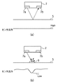
図2は、補正パターン検知センサ7の構成および補正パターンの検知方法を説明する図である。図2(a)に示すように補正パターン検知センサ7は、例えば、発光部7aから中間転写ベルト5へ照射した光の正反射成分を受光部7bで受光することにより補正パターンの検出を行う反射型光学センサにより構成することが可能である。図2(a)の中間転写ベルト5上に検出対象となる補正パターンが何も無い場合、照射した光の正反射光が十分であるため補正パターン検知センサ7のセンサ出力は高い出力(High出力)状態になる。
(Description of correction pattern detection sensor)
FIG. 2 is a diagram illustrating the configuration of the correction
一方、図2(b)に示すように、中間転写ベルト5上に補正パターン9等のトナー像がある場合は、光の乱反射成分が多くなり、正反射成分は少なくなるため、センサ出力は低い出力(Low出力)状態になる。本実施形態に係る画像形成装置は、中間転写ベルト5上のトナー像を検出する際に、補正パターン検知センサ7による照射光量を調整することが可能である。
On the other hand, as shown in FIG. 2B, when there is a toner image such as the
(制御ユニットの構成)
図10は、画像形成装置の制御ユニットの構成を示すブロック図であり、制御ユニットは、補正パターン検知センサ7等の検知結果に基づいて画像形成位置を補正するための制御を実行することが可能である。
(Configuration of control unit)
FIG. 10 is a block diagram illustrating the configuration of the control unit of the image forming apparatus. The control unit can execute control for correcting the image forming position based on the detection result of the correction
図10において、補正パターン検知センサ7は、図2で説明したとおり、中間転写ベルト5上に形成されたトナー像を検出するための反射型光学センサである。補正パターン検知センサ7は、中間転写ベルト5の表面あるいは、中間転写ベルト5の表面に形成されたトナー像からの反射光を受光部7bにより受光する。そして、補正パターン検知センサ7は、受光量を電圧変換して出力する。
In FIG. 10, the correction
補正パターン検知センサ7の出力電圧信号は、コンパレータ102、A/Dコンバータ103に入力される。コンパレータ102は、補正パターン検知センサ7からの出力電圧信号が所定の閾値より上回っているか否かを判別して、判別結果を2値化したデジタル信号により出力する。A/Dコンバータ103は、補正パターン検知センサ7からの出力電圧信号(アナログ出力電圧信号)をデジタル信号に変換して、制御ユニットの全体的は制御を司るCPU108に出力する。
The output voltage signal of the correction
ASIC104は、デジタル集積回路であり、パターン生成部105、パターン読み取り制御部106、レジストずれ算出部107、レジタイミング調整部118を有する。
The
ここで、パターン生成部105は、中間転写ベルト5上に形成する補正パターン用の画像データを生成する。
Here, the
パターン読み取り制御部106は、コンパレータ102により2値化された補正パターン検知センサ7の出力信号を読み取り、一時的にデータを格納することが可能である。レジストずれ算出部107は、補正パターン検知センサ7が読み取った補正パターンの検知結果に基づいて用紙とトナー画像との画像形成タイミングのずれを算出する。また、レジタイミング調整部118は、レジストずれ算出部107により算出された画像形成タイミングのずれに基づいて用紙搬送のタイミングを制御する。
The pattern
CPU108は制御ユニットの中枢であり、画像形成位置の補正制御の実行タイミング含め、各種命令を制御することが可能である。CPU108が実行する制御は、ROM111に格納されているプログラムデータに基づいて実行される。プログラムデータには、画像形成位置の補正制御における光量調整制御プログラム109が含まれている。
The
CPU108が実行する光量調整制御において、CPU108は、補正パターン検出センサ7の発光部7aの発光出力(光量)を制御することが可能である。例えば、補正パターン検出センサ7の発光部7aの発光出力は、CPU108の制御により最小の発光出力または最大の発光出力、あるいは発光部7aを構成するLEDの駆動電流に応じた照射光の光量調整が可能である。
In the light amount adjustment control executed by the
SRAM112には、CPU108が実行する光量調整制御プログラム109の制御で決定された補正パターン検知センサ7における発光部7aのLED駆動電流値など画像形成装置固有のデータが格納される。
The
画像処理制御部202は、CPU108の命令によって各種画像処理における中間調濃度の調整等を実行することが可能である。画像形成装置には、外部の温度や湿度を検出するための環境センサ203が具備されており、環境センサ203の出力はA/Dコンバータ103によってデジタル信号に変換されて、CPU108に入力される。
The image
CPU108は環境センサ203からの入力に基づいて、画像処理制御部202を制御することが可能である。すなわち、画像処理制御部202は、環境センサ203の入力に基づくCPU108の命令に基づいて、各種画像処理における中間調濃度の調整等を実行する。
The
(光量調整)
次に、第1実施形態に係る画像形成装置の光量調整について説明する。中間転写ベルト5の表面に対する反射光量と補正パターンに対する反射光量とが所定の光量差となるように、発光部の照射光量を調整する。
(Light intensity adjustment)
Next, light amount adjustment of the image forming apparatus according to the first embodiment will be described. The amount of light emitted from the light emitting unit is adjusted so that the amount of reflected light with respect to the surface of the
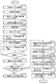
図3は本実施形態に係る画像形成装置における光量調整の流れを説明する図であり、光量調整はCPU108の制御の下に実行される。
FIG. 3 is a diagram for explaining the flow of light amount adjustment in the image forming apparatus according to the present embodiment. The light amount adjustment is executed under the control of the
まず、CPU108は、光量調整シーケンスをスタートさせると、ステップS301において、中間転写ベルト5を回転させる。
First, when starting the light amount adjustment sequence, the
ステップS302において、CPU108は、補正パターン検知センサ7を制御して、発光部7aは最大光量の照射光を中間転写ベルト5の表面上に出力する。
In step S <b> 302, the
ステップS303において、補正パターン検知センサ7の受光部7bは、ステップS302で照射された最大光量の照射光に対する、中間転写ベルト5の表面1周分、所定のサンプリング周期で反射光量(Amax)を測定する。
In step S303, the
次に、ステップS304において、CPU108は、補正パターン検知センサ7を制御して、発光部7aは最小光量の照射光を中間転写ベルト5の表面上に出力する。
In step S <b> 304, the
ステップS305において、補正パターン検知センサ7の受光部7bは、ステップS304で照射された最小光量の照射光に対する中間転写ベルト5の表面1周分、所定のサンプリング周期で反射光量(Amin)を測定する。
In step S305, the
ステップS303、S305において測定された最大光量に対する反射光量(Amax)と最小光量に対する反射光量(Amin)は後に説明するS311の処理で用いる。 The reflected light amount (Amax) with respect to the maximum light amount and the reflected light amount (Amin) with respect to the minimum light amount measured in steps S303 and S305 are used in the processing of S311 described later.
以上のステップにより、照射光量を最小にした場合と、最大にした場合の中間転写ベルト5に対する反射光量の測定結果(Amin、Amax)が得られる。測定されたデータは、例えば、ハードディスク等で構成することが可能な記憶ユニット185に格納される。
Through the above steps, the measurement result (Amin, Amax) of the reflected light amount with respect to the
次に、中間転写ベルト5に形成した補正パターンに対する反射光量を測定する。まず、ステップS306において、パターン生成部105により生成された画像データに基づく補正パターンを中間転写ベルト5に形成する。
Next, the amount of reflected light with respect to the correction pattern formed on the
ステップS307において、CPU108は、補正パターン検知センサ7を制御して、発光部7aは最小光量の照射光を、先のステップS306で形成した補正パターンに照射する。補正パターンからの反射光を受光部7bが受光する。
In step S307, the
発光部7aは、図9に示すように補正パターン901が補正パターン検知センサ7の検出位置に到達してから光量安定時間の経過後、サンプリング時間tsごとに、サンプリング回数Ns回、最小光量の照射光を補正パターン901に照射する。受光部7bは、補正パターン901からの反射光量を測定し、CPU108は、受光部7bの測定結果に基づいてサンプリング回数Nsの平均値をBminとする。
As shown in FIG. 9, the
ステップS308において、CPU108は、補正パターン検知センサ7を制御して、発光部7aは最大光量の照射光を出力する。
In step S308, the
そして、ステップS309において、パターン生成部105により生成された画像データに基づく補正パターンを中間転写ベルト5に形成する。尚、補正パターンは、ステップS306で形成したものを利用することも可能である。
In
ステップS310において、CPU108は、補正パターン検知センサ7を制御して、発光部7aは最大光量の照射光を、先のステップS309で形成した補正パターンに照射する。補正パターンからの反射光を受光部7bが受光する。
In step S310, the
発光部7aは、補正パターンが補正パターン検知センサ7の検出位置に到達してから光量安定時間の経過後、サンプリング時間tsごとに、サンプリング回数Ns回、最大光量の照射光を補正パターン901に照射する。受光部7bは、補正パターン901からの反射光量を測定し、CPU108は、受光部7bの測定結果に基づいてサンプリング回数Nsの平均値をBmaxとする。
The
以上のステップS306〜S310により、照射光量を最小にした場合と、最大にした場合の補正パターンに対する平均の反射光量の測定結果(Bmin、Bmax)が得られる。測定されたデータは記憶ユニット185に格納される。
Through the above steps S306 to S310, measurement results (Bmin, Bmax) of the average reflected light amount with respect to the correction pattern when the irradiation light amount is minimized and maximized are obtained. The measured data is stored in the
S311において、CPU108は、中間転写ベルト5に対する測定結果(Amin、Amax)と、発光部7aの最大光量Xmax、最小光量Xminと、から発光部の出力(照射光量)と受光部の受光量の線形補間関係Aref(1)式を算出する。
In S311, the
Aref=(Amax-Amin)/(Xmax-Xmin)・・・(1) Aref = (Amax−Amin) / (Xmax−Xmin) (1)
S312において、CPU108は、補正パターンに対する測定結果(Bmin、Bmax)と、発光部7aの最大光量Xmax、最小光量Xminと、から発光部の出力(照射光量)と、受光部の受光量の線形補間関係Bref(2)式を算出する。
In S312, the
Bref=(Bmax-Bmin)/(Xmax-Xmin)・・・(2) Bref = (Bmax−Bmin) / (Xmax−Xmin) (2)
CPU108は、中間転写ベルト5に対する測定結果(Amin、Amax)と、補正パターンに対する測定結果(Bmin、Bmax)と、に基づいて、図7に示す発光部の出力(照射光量)と、受光部の受光量の線形補間関係を求めることができる。この線形補間関係は、記憶ユニット185に格納される。
Based on the measurement results (Amin, Amax) for the
ステップS313において、CPU108は、Aref−Bref=差分光量Cref(所定値)となる光量Xを算出する。ここで、差分光量Cref(所定値)は、中間転写ベルトの材質や使用するトナーの種類により任意に設定することが可能である。また、個別に設定する場合のほか、例えば、(1)、(2)式の計算結果に基づいて、ArefとBrefの中間値をCrefとして用いることも可能である。この差分光量Cref(所定値)は、記憶ユニット185に格納されており、不図示の入力ユニットにより変更することが可能である。
In step S313, the
ステップS314において、CPU108は、補正パターンに対する発光部の出力(照射光量)と受光部の受光量の線形補間関係Bref(図7)に基づいて、ステップS313で算出された光量Xに対応する受光部7bの受光量Bxを求める。そして、受光量BxにCref(所定値)を加算したAx(=Cref+Bx)を中間転写ベルト5を識別するための反射光量(受光部の光量)として算出する。
In step S314, the
本実施形態に拠れば、補正パターンを安定して検出するための最小光量値を設定することが可能になる。 According to this embodiment, it is possible to set a minimum light amount value for stably detecting a correction pattern.
補正パターンを検知するために、中間転写ベルトに対する反射光量と補正パターンに対する反射光量との間に、一定の光量差を確保しつつ最小光量値を設定することで安定した補正パターンの検知が可能になる。すなわち、補正パターンのトナー濃度や転写ベルト表面の反射率が変化しても安定して補正パターンを検知することが可能になる。 In order to detect the correction pattern, it is possible to detect a stable correction pattern by setting a minimum light quantity value while ensuring a certain light quantity difference between the reflected light quantity for the intermediate transfer belt and the reflected light quantity for the correction pattern. Become. That is, the correction pattern can be stably detected even if the toner density of the correction pattern or the reflectance of the transfer belt surface changes.
あるいは、中間転写ベルトに対する反射光量と補正パターンに対する反射光量との間に一定の光量差を確保しつつ最小光量値を設定することで、補正パターン検知センサの発光部の寿命を長くすることが可能になる。 Alternatively, it is possible to extend the life of the light emitting part of the correction pattern detection sensor by setting a minimum light amount value while ensuring a constant light amount difference between the reflected light amount with respect to the intermediate transfer belt and the reflected light amount with respect to the correction pattern. become.
(第2実施形態)
次に、第2実施形態に係る画像形成装置の光量調整について説明する。図4は本実施形態に係る画像形成装置における光量調整の流れを説明する図であり、光量調整はCPU108の制御の下に実行される。第1実施形態に係る光量調整(図3)と同一の処理に関しては、同一のステップ番号を付して説明を省略する。ステップS301〜S304、S306〜S310は第1実施形態に係る光量調整と同一の処理となる。
(Second Embodiment)
Next, light amount adjustment of the image forming apparatus according to the second embodiment will be described. FIG. 4 is a diagram for explaining the flow of light amount adjustment in the image forming apparatus according to the present embodiment. The light amount adjustment is executed under the control of the
ステップS401において、CPU108は、補正パターン検知センサ7の受光部7bの暗電圧を測定し、この測定結果を最小光量の照射光に対する中間転写ベルト5の表面の反射光量として出力する。
In step S <b> 401, the
CPU108は、補正パターン検知センサ7の発光部7aを制御して、光量値を0にする。中間転写ベルト5表面の反射光量は0または暗電圧はほぼ一定値となるので、発光部7aがOFF時の受光部7bの出力を設定しておき、その値をAminとする。この場合、図7において、受光部の光量を示す縦軸の切片がAminに対応する。
The
S402において、CPU108は中間転写ベルト5に対する測定結果Amax、設定値Amin、発光部7aの最大光量Xmax、最小光量Xminと、から発光部の出力(照射光量)と受光部の受光量の線形補間関係Arefを算出する。
In S402, the
最小光量Xmin=0とした場合、Arefは(3)式により求めることができる。 When the minimum light amount Xmin = 0, Aref can be obtained by the equation (3).
Aref=(Amax-Amin)/(Xmax)・・・(3) Aref = (Amax−Amin) / (Xmax) (3)
ステップS312におけるBrefの算出は、(2)式を用いた第1実施形態の光量調整の処理(図3)と同一である。 The calculation of Bref in step S312 is the same as the light amount adjustment process (FIG. 3) of the first embodiment using the equation (2).
ステップS403において、CPU108は、(3)式より算出したArefに基づいて、Aref−Bref=差分光量Cref(所定値)となる光量Xを算出する。ここで、差分光量Cref(所定値)は、中間転写ベルトの材質や使用するトナーの種類により任意に設定することが可能である。また、個別に設定する場合のほか、例えば、(2)、(3)式の計算結果に基づいて、ArefとBrefの中間値をCrefとして用いることも可能である。
In step S <b> 403, the
そして、ステップS404において、CPU108は、補正パターンに対する発光部の出力(照射光量)と受光部の受光量の線形補間関係Bref(図7)に基づいて、ステップS403で算出された光量Xに対応する受光部7bの受光量Bxを求める。そして、受光量BxにCref(所定値)を加算したAx(=Cref+Bx)を中間転写ベルト5を識別するための反射光量(受光部の光量)として算出する。
In step S404, the
本実施形態に拠れば、光量調整の処理において、中間転写ベルト5の表面の反射光量(Amin)を測定せずに、暗電圧の測定結果を用いることで、光量調整時間を短縮することが可能になる。
According to this embodiment, the light amount adjustment time can be shortened by using the dark voltage measurement result without measuring the reflected light amount (Amin) of the surface of the
(第3実施形態)
次に、第3実施形態に係る画像形成装置の光量調整について説明する。図5は本実施形態に係る画像形成装置における光量調整の流れを説明する図であり、光量調整はCPU108の制御の下に実行される。第1及び第2実施形態に係る光量調整(図3、図4)と同一の処理に関しては、同一のステップ番号を付して説明を省略する。
(Third embodiment)
Next, light amount adjustment of the image forming apparatus according to the third embodiment will be described. FIG. 5 is a diagram for explaining the flow of light amount adjustment in the image forming apparatus according to the present embodiment. The light amount adjustment is executed under the control of the
ステップS301〜S304、S306、S307は第1実施形態に係る光量調整と同一の処理となり、S401は第2実施形態に係る光量調整と同一の処理となる。 Steps S301 to S304, S306, and S307 are the same processing as the light amount adjustment according to the first embodiment, and S401 is the same processing as the light amount adjustment according to the second embodiment.
ステップS501において、CPU108は、補正パターン検知センサ7を制御し、発光部7aは照射する光量を変更する。
In step S501, the
ステップS309における補正パターンの形成は、第1実施形態の処理と同様で、パターン生成部105により生成された画像データに基づく補正パターンを中間転写ベルト5に形成する。
The formation of the correction pattern in step S309 is similar to the processing of the first embodiment, and a correction pattern based on the image data generated by the
ステップS502において、発光部7aはステップS501で変更した光量の照射光を、先のステップS309で形成した補正パターンに照射する。補正パターンからの反射光を受光部7bが受光する。
In step S502, the
図8Aは、補正パターンに対する照射タイミングと光量の関係を概略的に示す図である。発光部7aは補正パターンが補正パターン検知センサ7の検出位置に到達してから光量安定時間の経過後、サンプリング時間tsごとに、サンプリング回数Ns回、変更した光量の照射光を補正パターン801に照射する(図8A)。受光部7bは、補正パターン801からの反射光量を測定し、CPU108は、受光部7bの測定結果に基づいてサンプリング回数Nsの平均値をBnとする。
FIG. 8A is a diagram schematically showing the relationship between the irradiation timing and the amount of light with respect to the correction pattern. The
ステップS503において、CPU108は、発光部7aの光量が最大光量に達しているか判定し、最大光量に達していない場合(S503−No)、処理をステップS501に戻し、同様の処理を補正パターン802、803に対して繰り返す。発光部7aの光量を順次、図8Aに示すように光量1・・・>光量3・・・>最大光量Nmaxまで増加させていき、各光量に対応する反射光量平均値Bnを測定する。測定されたデータは、例えば、記憶ユニット185に格納される。
In step S503, the
ステップS503の判定で発光部7aの光量が最大光量に達した場合(S503−Yes)、処理はステップS402に進められる。
When the light amount of the
この段階で、各光量に対応する反射光量平均値Bn(n=1(光量1)、2(光量2)、3(光量3)、・・・・・N(最大光量))の測定が完了する。 At this stage, measurement of the reflected light quantity average value Bn (n = 1 (light quantity 1), 2 (light quantity 2), 3 (light quantity 3),... N (maximum light quantity)) corresponding to each light quantity is completed. To do.
ステップS402では、第2実施形態で説明した(3)式の関係により、CPU108は発光部の出力(照射光量)と受光部の受光量の線形補間関係Arefを算出する。
In step S402, the
S504において、CPU108は、補正パターンに対する測定結果(Bn−1、Bn)と対応する発光部7aの光量Xn−1、光量Xnとから発光部の出力(照射光量)と受光部の受光量の線形補間関係Bnref(4)式を算出する。
In S504, the
Bnref=(Bn−Bn-1)/(Xn−Xn-1)・・・(4)(n=1〜Nmax) Bnref = (Bn−Bn−1) / (Xn−Xn−1) (4) (n = 1 to Nmax)
図7において、B2ref、B3ref、B4refは、それぞれ(4)式においてn=2、3、4とした場合に求められる。 In FIG. 7, B2ref, B3ref, and B4ref are obtained when n = 2, 3, and 4 in equation (4), respectively.
S505において、CPU108は、S504の算出結果に基づきAref−Bnref=差分光量Cref(所定値)となる光量Xを算出する。 In S505, the CPU calculates a light amount X that satisfies Aref−Bnref = difference light amount Cref (predetermined value) based on the calculation result in S504.
ここで、差分光量Cref(所定値)は、中間転写ベルトの材質や使用するトナーの種類により任意に設定することが可能である。また、個別に設定する場合のほか、例えば、(3)、(4)式の計算結果に基づいて、ArefとBnrefの中間値をCrefとして用いることも可能である。 Here, the difference light amount Cref (predetermined value) can be arbitrarily set depending on the material of the intermediate transfer belt and the type of toner used. In addition to setting individually, for example, an intermediate value between Aref and Bnref can be used as Cref based on the calculation results of equations (3) and (4).
S506において、CPU108は、補正パターンに対する発光部の出力(照射光量)と受光部の受光量の線形補間関係Bnrefに基づいて、ステップS505で算出された光量Xに対応する受光部7bの受光量Bxを求める。そして、受光量BxにCref(所定値)を加算したAx(=Cref+Bx)を中間転写ベルト5を識別するための反射光量(受光部の光量)として算出する。
In step S506, the
本実施形態に拠れば、発光部の光量の変更に対応した複数の計測結果を補間して用いることにより、発光部の光量と受光部の光量の関係を精度良く求めることが可能になる。その結果、補正パターンの誤検知を低減することが可能になる。 According to this embodiment, by interpolating and using a plurality of measurement results corresponding to the change in the light amount of the light emitting unit, the relationship between the light amount of the light emitting unit and the light amount of the light receiving unit can be accurately obtained. As a result, it is possible to reduce erroneous detection of the correction pattern.
(第4実施形態)
次に、第4実施形態に係る画像形成装置の光量調整について説明する。図6は本実施形態に係る画像形成装置における光量調整の流れを説明する図であり、光量調整はCPU108の制御の下に実行される。第1乃至第3実施形態に係る光量調整(図3、図4)と同一の処理に関しては、同一のステップ番号を付して説明を省略する。
(Fourth embodiment)
Next, light amount adjustment of the image forming apparatus according to the fourth embodiment will be described. FIG. 6 is a diagram illustrating the flow of light amount adjustment in the image forming apparatus according to the present embodiment, and the light amount adjustment is executed under the control of the
ステップS301〜S304は第1実施形態に係る光量調整と同一の処理であり、S401は第2実施形態に係る光量調整と同一の処理である。 Steps S301 to S304 are the same processing as the light amount adjustment according to the first embodiment, and S401 is the same processing as the light amount adjustment according to the second embodiment.
ステップS601において、パターン生成部105により生成された画像データに基づく補正パターンを中間転写ベルト5に形成する。図8Bは、補正パターンに対する照射タイミングと光量の関係を概略的に示す図である。図8Bに示すように、1つの補正パターン804に対して、照射光量を光量1〜光量4まで変化させて、受光部7bの受光量を計測する。補正パターン804のサイズは、複数の光量に対する計測を可能にする十分な長さを有するものとする。
In step S <b> 601, a correction pattern based on the image data generated by the
ここで、パターン生成部105は、発光部7aの光量安定時間、受光部7bのサンプリング時間、サンプリング回数、照射光量(図8Bの光量1〜光量4)の変更回数に基づいて補正パターンのサイズを決定することが可能である。
Here, the
ステップS602において、CPU108は、補正パターン検知センサ7を制御して、発光部7aは光量1の照射光を、先のステップS601で形成した補正パターン804に照射する。補正パターンからの反射光を受光部7bが受光する。測定条件の例として、光量1に上げた時の光量安定時間を20msと設定する。そして、サンプリング時間ts=10ms、サンプリング回数を7回として、測定結果の平均値をBminとする。
In step S602, the
ステップS603において、CPU108は、補正パターン検知センサ7を制御して、発光部7aの照射光量を所定値ごとに増加させる(例えば、図中8Bの場合、光量2に増加させる)。
In step S603, the
ステップS604において、発光部7aは光量安定時間の経過後、サンプリング時間tsごとに、サンプリング回数Ns回、変更した光量の照射光を補正パターン804に照射する(図8B)。受光部7bは、補正パターン804からの反射光量を測定し、CPU108は、受光部7bの測定結果に基づいてサンプリング回数Nsの平均値をBnとする。
In step S604, after the light amount stabilization time has elapsed, the
ステップS605において、CPU108は、発光部7aの光量が最大光量に達しているか判定し、最大光量に達していない場合(S605−No)、処理をステップS603に戻し、同様の処理を繰り返す。発光部7aの光量を順次、図8Bに示すように光量3、光量4と増加させていき、各光量に対応するBnを、最大光量(図8Bの場合は光量4)に達するまで測定する。
In step S605, the
ステップS605の判定で発光部7aの光量が最大光量に達した場合(S605−Yes)、処理はステップS402に進められる。
When the light quantity of the
この段階で、各光量に対応するBn(n=1(光量1)、2(光量2)、3(光量3)、4(光量4:最大光量))の測定が完了する。測定されたデータは、記憶ユニット185に格納される。
At this stage, measurement of Bn (n = 1 (light quantity 1), 2 (light quantity 2), 3 (light quantity 3), 4 (light quantity 4: maximum light quantity)) corresponding to each light quantity is completed. The measured data is stored in the
ステップS402では、第2実施形態で説明した(3)式の関係により、CPU108は発光部の出力(照射光量)と受光部の受光量の線形補間関係Aref(3)式を算出する。
In step S402, the
S606において、CPU108は、補正パターン804に対する測定結果(Bn−1、Bn)と、対応する発光部7aの光量Xn−1、光量Xnと、から発光部の出力(照射光量)と、受光部の受光量の線形補間関係Bnref(4)式を算出する。
In S606, the
S607において、CPU108は、S606の算出結果に基づきAref−Bnref=差分光量Cref(所定値)となる光量Xを算出する。
In S <b> 607, the
S608において、CPU108は、補正パターンに対する発光部の出力(照射光量)と受光部の受光量の線形補間関係Bnrefに基づいて、ステップS607で算出された光量Xに対応する受光部7bの受光量Bxを求める。そして、受光量BxにCref(所定値)を加算したAx(=Cref+Bx)を中間転写ベルト5を識別するための反射光量(受光部の光量)として算出する。
In step S <b> 608, the
本実施形態に拠れば、発光部の光量の変更に対応した複数の計測結果を補間して用いることにより、発光部の光量と受光部の光量の関係を精度良く求めることが可能になる。その結果、補正パターンの誤検知を低減することが可能になる。 According to this embodiment, by interpolating and using a plurality of measurement results corresponding to the change in the light amount of the light emitting unit, the relationship between the light amount of the light emitting unit and the light amount of the light receiving unit can be accurately obtained. As a result, it is possible to reduce erroneous detection of the correction pattern.
また、補正パターンを個別に形成するタイミングと、光量を変化させて反射光量を測定するタイミングと、を合わせるための処理の簡略化が可能になる。 Further, it is possible to simplify the processing for matching the timing for individually forming the correction pattern and the timing for measuring the reflected light amount by changing the light amount.
(第5実施形態)
次に、第5実施形態に係る画像形成装置の光量調整について説明する。中間転写ベルト5表面の傷の有無を判定し、その判定結果に基づいて発光部の照射光量を調整する。図3は本実施形態に係る画像形成装置における光量調整の流れを説明する図であり、光量調整はCPU108の制御の下に実行される。
(Fifth embodiment)
Next, light amount adjustment of the image forming apparatus according to the fifth embodiment will be described. The presence or absence of scratches on the surface of the
まず、CPU108は、光量調整シーケンスをスタートさせると、ステップS1101において、中間転写ベルト5を回転させる。
First, when starting the light amount adjustment sequence, the
ステップS1102において、CPU108は、補正パターン検知センサ7を制御して、発光部7aは最大光量の照射光を中間転写ベルト5の表面上に出力する。
In step S <b> 1102, the
ステップS1103において、補正パターン検知センサ7の受光部7bは、ステップS1102で照射された最大光量の照射光に対する中間転写ベルト5の表面の反射光量(Amax)を1周分、所定のサンプリング周期で測定する。
In step S1103, the
測定されたデータは、例えば、ハードディスク等で構成することが可能な記憶ユニット185に格納される。
The measured data is stored in a
ステップS1104において、CPU108は、補正パターン検知センサ7を制御して、発光部7aは最小光量の照射光を中間転写ベルト5の表面上に出力する。
In step S <b> 1104, the
ステップS1105において、補正パターン検知センサ7の受光部7bは、ステップS1104で照射された最小光量の照射光に対する中間転写ベルト5の表面の反射光量(Amin)を1周分、所定のサンプリング周期で測定する。
In step S1105, the
以上のステップにより、照射光量を最小にした場合と、最大にした場合の中間転写ベルト5に対する反射光量の測定結果(Amin、Amax)が得られる。測定されたデータは、記憶ユニット185に格納される。
Through the above steps, the measurement result (Amin, Amax) of the reflected light amount with respect to the
次に、中間転写ベルト5に形成した補正パターンに対する反射光量を測定する。まず、ステップS1106において、パターン生成部105により生成された画像データに基づく補正パターンを中間転写ベルト5に形成する。
Next, the amount of reflected light with respect to the correction pattern formed on the
ステップS1107において、CPU108は、補正パターン検知センサ7を制御して、発光部7aは最小光量の照射光を、先のステップS1106で形成した補正パターンに照射する。補正パターンからの反射光を受光部7bが受光する。
In step S1107, the
発光部7aは、図9に示すように補正パターンが補正パターン検知センサ7の検出位置に到達してから光量安定時間の経過後、サンプリング時間tsごとに、サンプリング回数Ns回、最小光量の照射光を補正パターン901に照射する。受光部7bは、補正パターン901からの反射光量を測定し、CPU108は、受光部7bの測定結果に基づいてサンプリング回数Nsの平均値をBminとする。測定されたデータは記憶ユニット185に格納される。
As shown in FIG. 9, the
ステップS1108において、CPU108は、補正パターン検知センサ7を制御して、発光部7aは最大光量の照射光を出力する。
In step S1108, the
そして、ステップS1109において、パターン生成部105により生成された画像データに基づく補正パターンを中間転写ベルト5に形成する。尚、補正パターンは、ステップS1106で形成したものを利用することも可能である。
In
ステップS1110において、CPU108は、補正パターン検知センサ7を制御して、発光部7aは最大光量の照射光を、先のステップS1109で形成した補正パターンに照射する。補正パターンからの反射光を受光部7bが受光する。
In step S1110, the
発光部7aは、補正パターンが補正パターン検知センサ7の検出位置に到達してから光量安定時間の経過後、サンプリング時間tsごとに、サンプリング回数Ns回、最大光量の照射光を補正パターン901に照射する。受光部7bは、補正パターン901からの反射光量を測定し、CPU108は、受光部7bの測定結果に基づいてサンプリング回数Nsの平均値をBmaxとする。測定されたデータは記憶ユニット185に格納される。
The
次に、ステップS1111において、CPU108は以下の(5)式により閾値光量Tを算出する。
Next, in step S <b> 1111, the
T=Bmax+D(所定値)・・・(5) T = Bmax + D (predetermined value) (5)
ここで、所定値Dは、中間転写ベルトの材質や使用するトナーの種類により任意に設定することが可能である。 Here, the predetermined value D can be arbitrarily set depending on the material of the intermediate transfer belt and the type of toner used.
ステップS1112において、CPU108は、閾値光量TとステップS1103で測定した中間転写ベルト1周分のAmaxとを比較して、閾値光量T以下となるAmaxの時間幅が規定時間tk以下であるか判定する。
In step S <b> 1112, the
CPU108が閾値光量T以下のAmaxの時間幅が規定時間tkより長いと判定する場合(S1112−No)、処理はステップS1119に進められ、CPU108は中間転写ベルトの寿命(中間転写ベルトの交換が必要)と判定する。
When the
一方、ステップS1112の判定で、CPU108が閾値光量T以下のAmaxの時間幅が規定時間tk以下と判定する場合(S1112−Yes)、処理はステップS1113に進められる。
On the other hand, if it is determined in step S1112 that the
ステップS1113において、CPU108は、閾値光量T以下の反射光量Amaxに対応する部分を中間転写ベルト5の傷と判定し、傷の部分をマスクする。
In step S <b> 1113, the
図15は、中間転写ベルト表面の反射光量Amaxと閾値光量Tの関係を例示する図である。閾値光量T以下となる時間幅がTk以下の場合、CPU108は、中間転写ベルト5の傷により表面の反射率が変動して反射光量Amaxが低下したと判定する。この判定結果に基づき、CPU108は、傷に対応するA1〜A2の反射光量を閾値光量Tに補正する(マスクする)。
FIG. 15 is a diagram illustrating the relationship between the reflected light amount Amax on the surface of the intermediate transfer belt and the threshold light amount T. When the time width that is equal to or smaller than the threshold light amount T is equal to or smaller than Tk, the
ステップS1114において、CPU108は、先のステップS1113でマスクした部分以外の反射光量Amaxから最低値A'maxを検出する。
In step S1114, the
S1115において、CPU108は、中間転写ベルト5に対する測定結果(Amin、A'max)と、発光部7aの最大光量Xmax、最小光量Xminとから発光部の出力(照射光量)と受光部の受光量の線形補間関係Aref(6)式を算出する。
In step S1115, the
Aref=(A'max-Amin)/(Xmax-Xmin)・・・(6) Aref = (A′max−Amin) / (Xmax−Xmin) (6)
S1116において、CPU108は、補正パターンに対する測定結果(Bmin、Bmax)と、発光部7aの最大光量Xmax、最小光量Xminと、から発光部の出力(照射光量)と、受光部の受光量の線形補間関係Bref(7)式を算出する。
In S1116, the
Bref=(Bmax-Bmin)/(Xmax-Xmin)・・・(7) Bref = (Bmax−Bmin) / (Xmax−Xmin) (7)
CPU108は、中間転写ベルト5に対する測定結果(Amin、A'max)と、補正パターンに対する測定結果(Bmin、Bmax)と、に基づいて、図7に示す発光部の出力(照射光量)と、受光部の受光量の線形補間関係を求めることができる。この線形補間関係は、記憶ユニット185に格納される。
Based on the measurement results (Amin, A′max) for the
ステップS1117において、CPU108は、Aref−Bref=差分光量Cref(所定値)となる光量Xを算出する。ここで、差分光量Cref(所定値)は、中間転写ベルトの材質や使用するトナーの種類により任意に設定することが可能である。また、個別に設定する場合のほか、例えば、(6)、(7)式の計算結果に基づいて、ArefとBrefの中間値をCrefとして用いることも可能である。
In step S <b> 1117, the
ステップS1118において、CPU108は、補正パターンに対する発光部の出力(照射光量)と受光部の受光量の線形補間関係Bref(図7)に基づいて、ステップS1117で算出された光量Xに対応する受光部7bの受光量Bxを求める。そして、受光量BxにCref(所定値)を加算したAx(=Cref+Bx)を中間転写ベルト5を識別するための反射光量(受光部の光量)として算出する。
In step S <b> 1118, the
本実施形態に拠れば、中間転写ベルトに傷があるか否か判定し、傷が存在する場合でも反射率の変動に影響されずに補正パターンを安定して検出するための最小光量値を設定することが可能になる。 According to this embodiment, it is determined whether or not the intermediate transfer belt is flawed, and even when there is a flaw, a minimum light amount value is set for stably detecting the correction pattern without being affected by the change in reflectance. It becomes possible to do.
補正パターンを検知するために、中間転写ベルトに対する反射光量と補正パターンに対する反射光量との間に、一定の光量差を確保しつつ最小光量値を設定することで安定した補正パターンの検知が可能になる。すなわち、補正パターンのトナー濃度や転写ベルト表面の反射率が傷の存在により変化しても安定して補正パターンを検知することが可能になる。 In order to detect the correction pattern, it is possible to detect a stable correction pattern by setting a minimum light quantity value while ensuring a certain light quantity difference between the reflected light quantity for the intermediate transfer belt and the reflected light quantity for the correction pattern. Become. That is, even if the toner density of the correction pattern or the reflectance of the transfer belt surface changes due to the presence of scratches, the correction pattern can be detected stably.
あるいは、中間転写ベルトに対する反射光量と補正パターンに対する反射光量との間に一定の光量差を確保しつつ最小光量値を設定することで、補正パターン検知センサの発光部の寿命を長くすることが可能になる。 Alternatively, it is possible to extend the life of the light emitting part of the correction pattern detection sensor by setting a minimum light amount value while ensuring a constant light amount difference between the reflected light amount with respect to the intermediate transfer belt and the reflected light amount with respect to the correction pattern. become.
(第6実施形態)
次に、第6実施形態に係る画像形成装置の光量調整について説明する。図12は本実施形態に係る画像形成装置における光量調整の流れを説明する図であり、光量調整はCPU108の制御の下に実行される。第5実施形態に係る光量調整(図11)と同一の処理に関しては、同一のステップ番号を付して説明を省略する。ステップS1101〜S1103、S1106〜S1110は第5実施形態に係る光量調整と同一の処理となる。
(Sixth embodiment)
Next, light amount adjustment of the image forming apparatus according to the sixth embodiment will be described. FIG. 12 is a diagram for explaining the flow of light amount adjustment in the image forming apparatus according to the present embodiment. The light amount adjustment is executed under the control of the
ステップS1201において、CPU108は補正パターン検知センサ7を制御して、発光部7aの光量値を0にする。
In step S1201, the
ステップS1202において、CPU108は、補正パターン検知センサ7の受光部7bの暗電圧を測定し、この測定結果を最小光量の照射光に対する中間転写ベルト5の表面の反射光量として出力する。中間転写ベルト5表面の反射光量は0または暗電圧はほぼ一定値となるので、発光部7aがOFF時の受光部7bの出力を設定しておき、その値をAminとする。
In step S <b> 1202, the
ステップS1111〜S1114、S1119は第5実施形態と同一の処理となる。 Steps S1111 to S1114 and S1119 are the same as those in the fifth embodiment.
S1203において、CPU108は中間転写ベルト5に対する測定結果A'max、設定値Amin、発光部7aの最大光量Xmax、最小光量Xmin=0とから発光部の出力(照射光量)と受光部の受光量の線形補間関係(8)式を算出する。
In step S1203, the
Aref=(A'max-Amin)/(Xmax)・・・(8) Aref = (A′max−Amin) / (Xmax) (8)
ステップS1116においけるBrefの算出は(7)式を用いた第5実施形態の光量調整の処理(図11)と同一である。 The calculation of Bref in step S1116 is the same as the light amount adjustment process (FIG. 11) of the fifth embodiment using equation (7).
S1204において、CPU108は、Aref−Bref=差分光量Cref(所定値)となる光量Xを算出する。ここで、差分光量Cref(所定値)は、中間転写ベルトの材質や使用するトナーの種類により任意に設定することが可能である。また、個別に設定する場合のほか、例えば、(7)、(8)式の計算結果に基づいて、ArefとBrefの中間値をCrefとして用いることも可能である。
In step S1204, the
S1205において、CPU108は、補正パターンに対する発光部の出力(照射光量)と受光部の受光量の線形補間関係Brefに基づいて、ステップS1204で算出された光量Xに対応する受光部7bの受光量Bxを求める。そして、受光量BxにCref(所定値)を加算したAx(=Cref+Bx)を中間転写ベルト5を識別するための反射光量(受光部の光量)として算出する。
In step S1205, the
本実施形態に拠れば、光量調整の処理において、中間転写ベルト5の表面の反射光量(Amin)を測定せずに、暗電圧の測定結果を用いることで、光量調整時間を短縮することが可能になる。
According to this embodiment, the light amount adjustment time can be shortened by using the dark voltage measurement result without measuring the reflected light amount (Amin) of the surface of the
(第7実施形態)
次に、第7実施形態に係る画像形成装置の光量調整について説明する。図13は本実施形態に係る画像形成装置における光量調整の流れを説明する図であり、光量調整はCPU108の制御の下に実行される。第5及び第6実施形態に係る光量調整(図11、図12)と同一の処理に関しては、同一のステップ番号を付して説明を省略する。
(Seventh embodiment)
Next, light amount adjustment of the image forming apparatus according to the seventh embodiment will be described. FIG. 13 is a diagram for explaining the flow of light amount adjustment in the image forming apparatus according to the present embodiment. The light amount adjustment is executed under the control of the
ステップS1101〜S1103、S1106、S1107は第5実施形態に係る光量調整と同一の処理となり、S1201、S1202は第6実施形態に係る光量調整と同一の処理となる。 Steps S1101 to S1103, S1106, and S1107 are the same processing as the light amount adjustment according to the fifth embodiment, and S1201 and S1202 are the same processing as the light amount adjustment according to the sixth embodiment.
ステップS1301において、CPU108は、補正パターン検知センサ7を制御し、発光部7aは照射する光量を変更する。
In step S1301, the
ステップS1109における補正パターンの形成は、第5実施形態の処理と同様で、パターン生成部105により生成された画像データに基づく補正パターンを中間転写ベルト5に形成する。
The formation of the correction pattern in step S1109 is similar to the process of the fifth embodiment, and a correction pattern based on the image data generated by the
ステップS1302において、発光部7aはステップS1301で変更した光量の照射光を、先のステップS1109で形成した補正パターンに照射する。補正パターンからの反射光を受光部7bが受光する。ここで、補正パターンに対する照射タイミングと光量の関係は、図8Aで説明したのと同様となる。
In step S1302, the
ステップS1303において、CPU108は、発光部7aの光量が最大光量に達しているか判定する。最大光量に達していない場合(S1303−No)、処理をステップS1301に戻し、同様の処理を補正パターン802、803(図8A)に対して繰り返す。発光部7aの光量を順次、図8Aに示すように光量1・・・>光量3・・・>最大光量Nmaxまで増加させていき、各光量に対応する反射光量平均値Bnを測定する。測定されたデータは記憶ユニット185に格納される。
In step S1303, the
ステップS1303の判定で発光部7aの光量が最大光量に達した場合(S1303−Yes)、処理はステップS1111に進められる。
If it is determined in step S1303 that the light amount of the
この段階で、各光量に対応する反射光量平均値Bn(n=1(光量1)、2(光量2)、3(光量3)、・・・・・N(最大光量))の測定が完了する。 At this stage, measurement of the reflected light quantity average value Bn (n = 1 (light quantity 1), 2 (light quantity 2), 3 (light quantity 3),... N (maximum light quantity)) corresponding to each light quantity is completed. To do.
ステップS1111〜S1114、S1119の処理は第5実施形態に係る光量調整と同一の処理となる。 The processing in steps S1111 to S1114 and S1119 is the same processing as the light amount adjustment according to the fifth embodiment.
ステップS1304において、CPU108は中間転写ベルト5に対する測定結果A'max、設定値Amin、発光部7aの最大光量Xmax、最小光量Xmin=0とから発光部の出力(照射光量)と受光部の受光量の線形補間関係Arefを算出する。Arefは第6実施形態の(8)式により算出することが可能である。
In step S1304, the
ステップS1305において、CPU108は、補正パターンに対する測定結果(Bn−1、Bn)と対応する発光部7aの光量Xn−1、光量Xnとから発光部の出力(照射光量)と受光部の受光量の線形補間関係Bnrefを算出する。Bnrefは第3実施形態で説明した(4)式により計算することが可能である。
In step S1305, the
ステップS1306において、CPU108は、S1304、S1305の算出結果に基づきAref−Bnref=差分光量Cref(所定値)となる光量Xを算出する。
In step S <b> 1306, the
ステップS1307において、CPU108は、補正パターンに対する発光部の出力(照射光量)と受光部の受光量の線形補間関係Bnrefに基づいて、ステップS1306で算出された光量Xに対応する受光部7bの受光量Bxを求める。そして、受光量BxにCref(所定値)を加算したAx(=Cref+Bx)を中間転写ベルト5を識別するための反射光量(受光部の光量)として算出する。
In step S1307, the
本実施形態に拠れば、発光部の光量の変更に対応した複数の計測結果を補間して用いることにより、発光部の光量と受光部の光量の関係を精度良く求めることが可能になる。その結果、補正パターンの誤検知を低減することが可能になる。 According to this embodiment, by interpolating and using a plurality of measurement results corresponding to the change in the light amount of the light emitting unit, the relationship between the light amount of the light emitting unit and the light amount of the light receiving unit can be accurately obtained. As a result, it is possible to reduce erroneous detection of the correction pattern.
(第8実施形態)
次に、第8実施形態に係る画像形成装置の光量調整について説明する。図14は本実施形態に係る画像形成装置における光量調整の流れを説明する図であり、光量調整はCPU108の制御の下に実行される。第5乃至第7実施形態に係る光量調整(図11、図12)と同一の処理に関しては、同一のステップ番号を付して説明を省略する。
(Eighth embodiment)
Next, light amount adjustment of the image forming apparatus according to the eighth embodiment will be described. FIG. 14 is a diagram for explaining the flow of light amount adjustment in the image forming apparatus according to the present embodiment, and the light amount adjustment is executed under the control of the
ステップS1101〜S1103は第5実施形態に係る光量調整と同一の処理であり、S1201、S1202は第6実施形態に係る光量調整と同一の処理である。 Steps S1101 to S1103 are the same processing as the light amount adjustment according to the fifth embodiment, and S1201 and S1202 are the same processing as the light amount adjustment according to the sixth embodiment.
ステップS1401において、パターン生成部105により生成された画像データに基づく補正パターン804(図8B)を中間転写ベルト5に形成する。
In step S1401, a correction pattern 804 (FIG. 8B) based on the image data generated by the
ステップS1402において、CPU108は、補正パターン検知センサ7を制御して、発光部7aは光量1(図8B)の照射光を、先のステップS1401で形成した補正パターン804に照射する。補正パターンからの反射光を受光部7bが受光し、この測定結果の平均値をBminとする。
In step S1402, the
ステップS1403において、CPU108は、補正パターン検知センサ7を制御して、発光部7aの照射光量を所定値ごとに増加させる(例えば、図中8Bの場合、光量2に増加させる)。
In step S1403, the
ステップS1404において、発光部7aは光量安定時間の経過後、サンプリング時間tsごとに、サンプリング回数Ns回、変更した光量の照射光を補正パターン804に照射する(図8B)。受光部7bは、補正パターン804からの反射光量を測定し、CPU108は、受光部7bの測定結果に基づいてサンプリング回数Nsの平均値をBnとする。
In step S1404, the
ステップS1405において、CPU108は、発光部7aの光量が最大光量に達しているか判定し、最大光量に達していない場合(S1405−No)、処理をステップS1403に戻し、同様の処理を繰り返す。発光部7aの光量を順次、図8Bに示すように光量3、光量4と増加させていき、各光量に対応するBnを、最大光量(図8Bの場合は光量4)に達するまで測定する。
In step S1405, the
ステップS1405の判定で発光部7aの光量が最大光量に達した場合(S1405−Yes)、処理はステップS1111に進められる。
If it is determined in step S1405 that the light amount of the
この段階で、各光量に対応するBn(n=1(光量1)、2(光量2)、3(光量3)、4(光量4:最大光量))の測定が完了する。測定されたデータは記憶ユニット185に格納される。
At this stage, measurement of Bn (n = 1 (light quantity 1), 2 (light quantity 2), 3 (light quantity 3), 4 (light quantity 4: maximum light quantity)) corresponding to each light quantity is completed. The measured data is stored in the
ステップS1111〜S1114、S1119の処理は第5実施形態に係る光量調整と同一の処理となる。 The processing in steps S1111 to S1114 and S1119 is the same processing as the light amount adjustment according to the fifth embodiment.
ステップS1405において、CPU108は中間転写ベルト5に対する測定結果A'max、設定値Amin、発光部7aの最大光量Xmax、最小光量Xmin=0とから発光部の出力(照射光量)と受光部の受光量の線形補間関係Arefを算出する。Arefは第6実施形態の(8)式により算出することが可能である。
In step S1405, the
ステップS1406において、CPU108は、補正パターンに対する測定結果(Bn−1、Bn)と対応する発光部7aの光量Xn−1、光量Xnとから発光部の出力(照射光量)と受光部の受光量の線形補間関係Bnrefを算出する。Bnrefは第3実施形態で説明した(4)式により計算することが可能である。
In step S1406, the
ステップS1407において、CPU108は、S1405、S1406の算出結果に基づきAref−Bnref=差分光量Cref(所定値)となる光量Xを算出する。
In step S1407, the
ステップS1408において、CPU108は、補正パターンに対する発光部の出力(照射光量)と受光部の受光量の線形補間関係Bnrefに基づいて、ステップS1407で算出された光量Xに対応する受光部7bの受光量Bxを求める。そして、受光量BxにCref(所定値)を加算したAx(=Cref+Bx)を中間転写ベルト5を識別するための反射光量(受光部の光量)として算出する。
In step S1408, the
本実施形態に拠れば、発光部の光量の変更に対応した複数の計測結果を補間して用いることにより、発光部の光量と受光部の光量の関係を精度良く求めることが可能になる。その結果、補正パターンの誤検知を低減することが可能になる。 According to this embodiment, by interpolating and using a plurality of measurement results corresponding to the change in the light amount of the light emitting unit, the relationship between the light amount of the light emitting unit and the light amount of the light receiving unit can be accurately obtained. As a result, it is possible to reduce erroneous detection of the correction pattern.
また、本実施形態に拠れば、補正パターンを個別に形成するタイミングと、光量を変化させて反射光量を測定するタイミングと、を合わせるための処理の簡略化が可能になる。 Further, according to the present embodiment, it is possible to simplify the process for matching the timing for individually forming the correction pattern and the timing for measuring the reflected light amount by changing the light amount.
(他の実施形態)
なお、本発明の目的は、前述した実施形態の機能を実現するソフトウェアのプログラムコードを記録した記憶媒体を、システムあるいは装置に供給することによっても、達成されることは言うまでもない。また、システムあるいは装置のコンピュータ(またはCPUやMPU)が記憶媒体に格納されたプログラムコードを読出し実行することによっても、達成されることは言うまでもない。
(Other embodiments)
Needless to say, the object of the present invention can also be achieved by supplying a storage medium storing software program codes for realizing the functions of the above-described embodiments to a system or apparatus. Needless to say, this can also be achieved by the computer (or CPU or MPU) of the system or apparatus reading and executing the program code stored in the storage medium.
この場合、記憶媒体から読出されたプログラムコード自体が前述した実施形態の機能を実現することになり、そのプログラムコードを記憶した記憶媒体は本発明を構成することになる。 In this case, the program code itself read from the storage medium realizes the functions of the above-described embodiments, and the storage medium storing the program code constitutes the present invention.
プログラムコードを供給するための記憶媒体としては、例えば、フレキシブルディスク、ハードディスク、光ディスク、光磁気ディスク、CD−ROM、CD−R、不揮発性のメモリカード、ROMなどを用いることができる。 As a storage medium for supplying the program code, for example, a flexible disk, a hard disk, an optical disk, a magneto-optical disk, a CD-ROM, a CD-R, a nonvolatile memory card, a ROM, or the like can be used.
また、コンピュータが読出したプログラムコードを実行することにより、前述した実施形態の機能が実現される。また、プログラムコードの指示に基づき、コンピュータ上で稼働しているOS(オペレーティングシステム)などが実際の処理の一部または全部を行い、その処理によって前述した実施形態が実現される場合も含まれることは言うまでもない。 Further, the functions of the above-described embodiment are realized by executing the program code read by the computer. In addition, an OS (operating system) running on a computer performs part or all of actual processing based on an instruction of a program code, and the above-described embodiment is realized by the processing. Needless to say.
3 ベルト支持ローラ
4 転写ローラ
5 中間転写ベルト
6 カラートナー画像
7 補正パターン検知センサ
10 搬送ローラ
13 レジストローラ
102 コンパレータ
103 A/Dコンバータ
104 ASIC
105 パターン生成部
106 パターン読み取り制御部
107 レジストずれ算出部
108 CPU
118 レジタイミング調整部
202 画像処理制御部
3 Belt Support Roller 4
105
118 Registration
Claims (8)
前記像担持ベルト及び前記パターンに照射する照射光量を制御する光量制御手段と、
前記照射光量に対する、前記像担持ベルト及び前記パターンからの反射光量をそれぞれ検知する検知手段と、
検知結果に基づき、前記照射光量と前記反射光量との対応関係を、前記像担持ベルト及び前記パターンそれぞれについて算出する演算手段と、
前記対応関係に基づいて、前記像担持ベルトからの反射光量と前記パターンからの反射光量との差分が予め定められた値となる光量を決定する光量決定手段と、
を備えることを特徴とする画像形成装置。 Pattern forming means for forming a light amount adjustment pattern on the image bearing belt;
A light amount control means for controlling the amount of light applied to the image bearing belt and the pattern;
With respect to the irradiation light amount, and detecting means you each test known amount of light reflected from the image bearing belt and the pattern,
Based on the detection result, and calculating means that the correspondence between the radiation light amount and the reflection light amount, out calculation for each of the image bearing belt and the pattern,
Based on the correspondence relation, the light amount determining means for determining the amount of light becomes a value difference is a predetermined of amount of reflected light from the reflected light and the pattern from the image bearing belt,
An image forming apparatus comprising:
Priority Applications (4)
| Application Number | Priority Date | Filing Date | Title |
|---|---|---|---|
| JP2006279155A JP4850651B2 (en) | 2006-10-12 | 2006-10-12 | Image forming apparatus |
| US11/871,630 US7590364B2 (en) | 2006-10-12 | 2007-10-12 | Image forming apparatus with irradiated light control based on reflected light amounts |
| US12/534,197 US7991336B2 (en) | 2006-10-12 | 2009-08-03 | Image forming apparatus with irradiated light control based on reflected light amounts |
| US13/168,326 US8175505B2 (en) | 2006-10-12 | 2011-06-24 | Image forming apparatus with emitted light control based on reflected light amounts |
Applications Claiming Priority (1)
| Application Number | Priority Date | Filing Date | Title |
|---|---|---|---|
| JP2006279155A JP4850651B2 (en) | 2006-10-12 | 2006-10-12 | Image forming apparatus |
Publications (3)
| Publication Number | Publication Date |
|---|---|
| JP2008096744A JP2008096744A (en) | 2008-04-24 |
| JP2008096744A5 JP2008096744A5 (en) | 2009-11-26 |
| JP4850651B2 true JP4850651B2 (en) | 2012-01-11 |
Family
ID=39303213
Family Applications (1)
| Application Number | Title | Priority Date | Filing Date |
|---|---|---|---|
| JP2006279155A Expired - Fee Related JP4850651B2 (en) | 2006-10-12 | 2006-10-12 | Image forming apparatus |
Country Status (2)
| Country | Link |
|---|---|
| US (3) | US7590364B2 (en) |
| JP (1) | JP4850651B2 (en) |
Families Citing this family (16)
| Publication number | Priority date | Publication date | Assignee | Title |
|---|---|---|---|---|
| WO2007130068A1 (en) * | 2006-05-10 | 2007-11-15 | Hewlett-Packard Development Company, Lp. | A correction method, apparatus, data carrier or system for correcting for unintended spatial variation in lightness across a physical image produced by a xerographic process |
| JP4965961B2 (en) * | 2006-10-12 | 2012-07-04 | キヤノン株式会社 | Image forming apparatus |
| JP2010026210A (en) * | 2008-07-18 | 2010-02-04 | Konica Minolta Business Technologies Inc | Image forming apparatus and image forming system |
| JP5344601B2 (en) * | 2009-07-01 | 2013-11-20 | キヤノン株式会社 | Image forming apparatus and method of controlling image forming apparatus |
| JP5534399B2 (en) * | 2009-08-27 | 2014-06-25 | 株式会社リコー | Image forming apparatus |
| KR101639808B1 (en) * | 2009-10-14 | 2016-07-14 | 삼성전자 주식회사 | Image forming apparatus and auto color registration method thereof |
| JP5623252B2 (en) * | 2010-11-15 | 2014-11-12 | キヤノン株式会社 | Image forming apparatus |
| KR101866805B1 (en) * | 2011-03-03 | 2018-06-18 | 에이치피프린팅코리아 주식회사 | Image forming apperatus and method for color registration correction |
| JP6200138B2 (en) | 2012-09-18 | 2017-09-20 | キヤノン株式会社 | Image forming apparatus |
| JP6225456B2 (en) * | 2013-04-03 | 2017-11-08 | コニカミノルタ株式会社 | Image forming apparatus |
| JP6192615B2 (en) * | 2013-08-30 | 2017-09-06 | 京セラドキュメントソリューションズ株式会社 | Image forming apparatus and image forming method |
| JP6374670B2 (en) * | 2014-02-26 | 2018-08-15 | キヤノン株式会社 | Image forming apparatus and control method thereof |
| JP6335013B2 (en) * | 2014-04-30 | 2018-05-30 | キヤノン株式会社 | Image forming apparatus |
| JP6624772B2 (en) * | 2014-06-13 | 2019-12-25 | キヤノン株式会社 | Image forming apparatus, light amount control method, and control method for image forming apparatus |
| JP2019028246A (en) * | 2017-07-31 | 2019-02-21 | キヤノン株式会社 | Image forming apparatus |
| US10558135B1 (en) * | 2019-01-25 | 2020-02-11 | Toshiba Tec Kabushiki Kaisha | Image forming apparatus and carrying control method |
Family Cites Families (13)
| Publication number | Priority date | Publication date | Assignee | Title |
|---|---|---|---|---|
| JP3105268B2 (en) * | 1990-12-22 | 2000-10-30 | 株式会社リコー | Image forming device |
| JPH06127039A (en) | 1992-10-15 | 1994-05-10 | Fuji Xerox Co Ltd | Registration correcting device |
| JP3500008B2 (en) * | 1996-05-28 | 2004-02-23 | 株式会社リコー | Developing ability detection method in image forming apparatus |
| US6285849B1 (en) * | 1998-09-11 | 2001-09-04 | Matsushita Electric Industrial Co., Ltd. | Color image forming apparatus |
| JP2000127499A (en) * | 1998-10-26 | 2000-05-09 | Canon Inc | Image-forming apparatus and its control method |
| JP4124980B2 (en) | 2000-05-31 | 2008-07-23 | キヤノン株式会社 | Image forming apparatus and registration correction method |
| US6611666B2 (en) * | 2001-06-15 | 2003-08-26 | Nexpress Solutions Llc | Densitometer with improved accuracy for use in color image processing apparatus |
| JP4407084B2 (en) * | 2001-07-27 | 2010-02-03 | コニカミノルタビジネステクノロジーズ株式会社 | Image forming apparatus |
| JP2003228216A (en) * | 2002-02-04 | 2003-08-15 | Canon Inc | Image forming apparatus |
| JP3976012B2 (en) * | 2004-01-23 | 2007-09-12 | ブラザー工業株式会社 | Patch density measuring apparatus and image forming apparatus |
| JP4485961B2 (en) * | 2005-01-07 | 2010-06-23 | 株式会社リコー | Light amount adjusting device, color shift amount detecting device, and image forming apparatus |
| JP4695899B2 (en) | 2005-03-14 | 2011-06-08 | キヤノン株式会社 | Image forming apparatus |
| JP2006258906A (en) | 2005-03-15 | 2006-09-28 | Canon Inc | Color image forming apparatus and its color slippage compensation method |
-
2006
- 2006-10-12 JP JP2006279155A patent/JP4850651B2/en not_active Expired - Fee Related
-
2007
- 2007-10-12 US US11/871,630 patent/US7590364B2/en not_active Expired - Fee Related
-
2009
- 2009-08-03 US US12/534,197 patent/US7991336B2/en not_active Expired - Fee Related
-
2011
- 2011-06-24 US US13/168,326 patent/US8175505B2/en active Active
Also Published As
| Publication number | Publication date |
|---|---|
| US20080089702A1 (en) | 2008-04-17 |
| US7590364B2 (en) | 2009-09-15 |
| US20110255908A1 (en) | 2011-10-20 |
| US20090297200A1 (en) | 2009-12-03 |
| US7991336B2 (en) | 2011-08-02 |
| US8175505B2 (en) | 2012-05-08 |
| JP2008096744A (en) | 2008-04-24 |
Similar Documents
| Publication | Publication Date | Title |
|---|---|---|
| JP4850651B2 (en) | Image forming apparatus | |
| US9389564B2 (en) | Image forming apparatus for performing registration and density correction control | |
| JP5839833B2 (en) | Image forming apparatus | |
| JP4419101B2 (en) | Image forming apparatus | |
| JP6685753B2 (en) | Image forming device | |
| JP5822507B2 (en) | Image forming apparatus | |
| JP3976012B2 (en) | Patch density measuring apparatus and image forming apparatus | |
| JPH11249374A (en) | Image forming device | |
| JP4402509B2 (en) | Image forming apparatus | |
| JP2013109208A (en) | Image forming apparatus, and method for forming toner image for gradation correction | |
| JP2007079100A (en) | Image forming apparatus | |
| JP5092514B2 (en) | Image forming apparatus | |
| JP2008287185A (en) | Image forming apparatus and control method therefor | |
| JP2017207591A (en) | Image forming apparatus | |
| JP4661142B2 (en) | Color image forming apparatus | |
| JP2008032848A (en) | Paper surface property detection sensor and image forming apparatus equipped therewith | |
| JP2006308812A (en) | Image forming apparatus and control method therefor | |
| JP6921489B2 (en) | Image forming device | |
| JP2008209659A (en) | Image forming device and control method | |
| JP2007223740A (en) | Image forming apparatus | |
| JP2013120215A (en) | Image forming apparatus | |
| JP2021173978A (en) | Image forming apparatus | |
| JP2006039389A (en) | Color image forming apparatus | |
| JP2012159605A (en) | Image forming device | |
| JP2000056527A (en) | Image forming device |
Legal Events
| Date | Code | Title | Description |
|---|---|---|---|
| A521 | Request for written amendment filed |
Free format text: JAPANESE INTERMEDIATE CODE: A523 Effective date: 20091013 |
|
| A621 | Written request for application examination |
Free format text: JAPANESE INTERMEDIATE CODE: A621 Effective date: 20091013 |
|
| TRDD | Decision of grant or rejection written | ||
| A01 | Written decision to grant a patent or to grant a registration (utility model) |
Free format text: JAPANESE INTERMEDIATE CODE: A01 Effective date: 20111014 |
|
| A01 | Written decision to grant a patent or to grant a registration (utility model) |
Free format text: JAPANESE INTERMEDIATE CODE: A01 |
|
| A61 | First payment of annual fees (during grant procedure) |
Free format text: JAPANESE INTERMEDIATE CODE: A61 Effective date: 20111019 |
|
| R151 | Written notification of patent or utility model registration |
Ref document number: 4850651 Country of ref document: JP Free format text: JAPANESE INTERMEDIATE CODE: R151 |
|
| FPAY | Renewal fee payment (event date is renewal date of database) |
Free format text: PAYMENT UNTIL: 20141028 Year of fee payment: 3 |
|
| LAPS | Cancellation because of no payment of annual fees |