JP4846331B2 - Photoelectric encoder and its scale - Google Patents
Photoelectric encoder and its scale Download PDFInfo
- Publication number
- JP4846331B2 JP4846331B2 JP2005293228A JP2005293228A JP4846331B2 JP 4846331 B2 JP4846331 B2 JP 4846331B2 JP 2005293228 A JP2005293228 A JP 2005293228A JP 2005293228 A JP2005293228 A JP 2005293228A JP 4846331 B2 JP4846331 B2 JP 4846331B2
- Authority
- JP
- Japan
- Prior art keywords
- scale
- value
- image
- photoelectric encoder
- correlation
- Prior art date
- Legal status (The legal status is an assumption and is not a legal conclusion. Google has not performed a legal analysis and makes no representation as to the accuracy of the status listed.)
- Active
Links
Images


Description
本発明は、スケール上のビットパターンの画像を検出器で取得して、スケールと検出器の相対変位を検出するようにされた光電式エンコーダ、及び、そのスケールに係り、特に、マイクロメータやインジケータ等のバッテリ駆動の小型変位測定機、更にリニアスケールに用いるのに好適な、光電式エンコーダ、及び、そのスケールに関する。 The present invention relates to a photoelectric encoder that acquires an image of a bit pattern on a scale with a detector and detects a relative displacement between the scale and the detector, and to the scale, and more particularly, to a micrometer and an indicator. The present invention relates to a small-sized displacement measuring machine driven by a battery such as a photoelectric encoder suitable for use in a linear scale, and the scale.
特許文献1〜4に記載されている如く、図1(特許文献4の例)に示すように、絶対位置を得ようとするバイナリパターンや、M系列等の擬似乱数列を表現したABSコード608を有するトラックをスケール607上に配置して、透過又は反射により得られる光信号を検出器601で検出し、その2値化された値から絶対位置を復号する光電式絶対位置検出(ABS)エンコーダが知られている。図において、600は検出ヘッド、601a、601bは、それぞれ、X方向終端又は前端のABSコード検出器、602はマーカ検出器、603は、シフトレジスタ604、変換回路605、606、シフトレジスタ制御信号発生回路610を備えた信号処理回路である。
As described in
しかしながら、この装置では、初期位置をスケール607又は検出ヘッド600の移動を行なわずに検出するためには、特許文献2のように、必要ビット長分の長い検出器が必要になる。
However, in this apparatus, in order to detect the initial position without moving the
又、別の手法としては、絶対位置を示すトラックを並列に必要ビット分配置して、同時に検出器も同数用意する方法もある。 As another method, there is a method in which tracks indicating absolute positions are arranged in parallel for necessary bits, and the same number of detectors are prepared at the same time.
更に、ビットパターンの境界で0か1か不定になるのを防ぐため、特許文献3のように、検出ポイントを3点に増やしたり、特許文献4のように、検出器を移動させる方法もある。
Further, in order to prevent 0 or 1 from becoming undefined at the boundary of the bit pattern, there are methods of increasing the number of detection points to 3 as in
あるいは、より高精度な位置を得るために、特許文献1〜4のように、図1に示した如く、インクリメンタルコード609を備えたトラックを併用し、内挿したインクリメンタルのカウントと絶対位置を合成することも行なわれている。
Alternatively, in order to obtain a more accurate position, as shown in FIGS. 1 to 4, a track having an
又、特許文献5のように、2次元のイメージセンサを用いて、画像相関を計算することも行なわれている。
Further, as in
しかしながら、単一のトラックで高精度を得るためには、スケールを微細加工しなければならず、コスト高になる。又、絶対位置コードの読出しが不正確になり勝ちである。更に、特許文献1乃至4のように、インクリメンタルのスケールトラックを併用する方法では、常時インクリメンタルの信号を読む必要があり、消費電力が増加してしまうため、低消費電力が必要なバッテリ駆動の機器への搭載が制限されてしまう。又、インクリメンタルトラックを増やす分だけコストも増加する。
However, in order to obtain high accuracy with a single track, the scale must be finely processed, resulting in high costs. In addition, reading of the absolute position code is likely to be inaccurate. Furthermore, as disclosed in
又、特許文献5のように、画像の半分相当の領域を用いて画像相関を行う方法では、例えば一次元のみの相関を行った場合でも、画像相関演算のための演算量が膨大で、そのままでは、消費電力、コスト、サイズの面からバッテリ駆動の小型変位測定機には採用できない等の問題点を有していた。
Further, in the method of performing image correlation using a region corresponding to half of the image as in
本発明は、前記従来の問題点を解決するべくなされたもので、低消費電力、低価格で且つ高精度、高分解能であって、より広範囲の絶対位置の表現や誤り訂正符号の付加が可能な光電式エンコーダ、及び、そのスケールを提供することを課題とする。 The present invention has been made to solve the above-mentioned conventional problems, and has low power consumption, low cost, high accuracy, and high resolution , and can express a wider range of absolute positions and add error correction codes. photoelectric encoder such, and the challenge is to provide the scale.
本発明は、スケール上のビットパターンの画像を検出器で取得して、スケールと検出器の相対変位を検出するようにされた光電式エンコーダにおいて、前記ビットパターンを、共通の部分とベクトル値が順次割り当てられた部分とでなるフレームパターンを持つように変調すると共に、前記ベクトル値を、擬似乱数列を、使用するベクトル値の次元で区切ったものとすることにより、前記課題を解決したものである。 The present invention is to obtain an image of the bit pattern on the scale at the detector, the photoelectric encoder which is adapted to detect the relative displacement of the scale and the detector, said bit pattern, a common portion and a vector value with modulated to have a frame pattern composed by sequentially allocated portion, the vector value, a pseudo-random number sequence, by a, separated by dimensional vector values used to solve the previous SL challenges Is.
又、前記変調されたビットパターン内に共通で現われる部分を参照画像として画像相関を行なうようにしたものである。 Further, image correlation is performed using a portion appearing in common in the modulated bit pattern as a reference image.
又、画像相関値のピーク位置を用いて、絶対位置コードのデコード開始位置を正確に決定できるようにしたものである。 Also, the decoding start position of the absolute position code can be accurately determined using the peak position of the image correlation value.
又、画像相関した値を使用して、最小二乗法によるフィッティングや特許文献5に記載の方法により、相関値の極値を高精度で推定できるようにしたものである。
Further, by using the image-correlated value, the extreme value of the correlation value can be estimated with high accuracy by the fitting by the least square method or the method described in
又、前記ピーク検出を必要最低限行なうことで、画像相関を終了するようにして、計算量を削減したものである。 Further, the amount of calculation is reduced by completing the image detection by performing the peak detection as much as possible.
又、得られた相関値の極値と絶対位置コードを合成することで、高精度な絶対位置が得られるようにしたものである。 Further, by combining the obtained extreme value of the correlation value and the absolute position code, a highly accurate absolute position can be obtained.
本発明は、又、共通の部分とベクトル値が順次割り当てられた部分とでなるフレームパターンを持つように変調されたビットパターンを備え、前記ベクトル値が、擬似乱数列を、使用するベクトル値の次元で区切ったものとされていることを特徴とする光電式エンコーダのスケールを提供するものである。 The present invention also includes a bit pattern modulated so as to have a frame pattern composed of a common part and a part to which vector values are sequentially assigned, and the vector value is a vector value using a pseudo-random number sequence. The present invention provides a scale for a photoelectric encoder characterized by being separated by dimensions .
本発明によれば、スケール上のビットパターンが共通の部分を持つように変調されているので、ビットパターンの位置を正確に知ることができ、境界で0か1か不定になって精度が低下することがない。従って、検出ポイントを増やしたり、検出器を移動したり、検出範囲を幅広くして検出器を大型化することなく、ビットパターンを正確に読み込むことが可能となり、1次元1トラックのスケールで、低消費電力、低価格の絶対位置用アブソリュートエンコーダを供給できる。
更に、前記ビットパターンにベクトル値を割り当てて多値化したので、より広範囲の絶対位置の表現や誤り訂正符号の付加が可能となる。
According to the present invention, since the bit pattern on the scale is modulated so as to have a common part, the position of the bit pattern can be accurately known and becomes 0 or 1 at the boundary and the accuracy is lowered. There is nothing to do. Therefore, it is possible to accurately read a bit pattern without increasing the number of detection points, moving the detector, widening the detection range, and increasing the size of the detector. Absolute encoder for absolute position with low power consumption and low price can be supplied.
Furthermore, since vector values are assigned to the bit pattern to make it multi-valued, it is possible to express a wider range of absolute positions and add error correction codes.
又、前記ベクトル値を、擬似乱数列を、使用するベクトル値の次元で区切ったものとしたので、絶対位置を単一のトラックで検出可能となる。 Further, the vector value, a pseudo-random number sequence, since those separated by vector dimension values to be used, it is possible to detect the absolute position in a single track.
又、前記変調されたビットパターン内に共通で現われる部分を参照画像として画像相関を行なうようにした場合には、演算量の少ない画像相関演算でも、高精度のエンコーダを実現できる。 In addition, when image correlation is performed using a portion that appears in common in the modulated bit pattern as a reference image, a highly accurate encoder can be realized even with image correlation calculation with a small amount of calculation.
以下図面を参照して、本発明の実施形態を詳細に説明する。 Hereinafter, embodiments of the present invention will be described in detail with reference to the drawings.
参考形態は、図2に示す如く、図3で示されるフレームパターンが、図4に示す如く、擬似乱数列で配置されたトラックのみを配置したスケール10と、発光素子22、レンズ24及び受光素子アレイ26が搭載された検出器20と、信号処理装置30とを備えている。
As shown in FIG. 2, the reference form is the
前記信号処理装置30は、前記受光素子アレイ26の出力のノイズを除去して増幅するためのノイズフィルタ・増幅回路32と、該ノイズフィルタ・増幅回路32の出力のアナログ信号をデジタル信号に変換するA/D変換器34と、該A/D変換器34の出力信号を補正する信号補正回路36と、該信号補正回路36の出力の相関演算を行なう相関演算回路38と、該相関演算回路38の出力により絶対(ABS)位置を演算するABS演算回路40と、該ABS演算回路40で得られたABS位置と前記相関演算回路38で得られた内挿位置を合成して絶対位置として出力する位置合成回路42とを含んで構成される。
The
このような構成において、前記レンズ24により拡大又は等倍とされたスケール10の透過像が受光素子アレイ26で検出され、検出信号は、信号処理装置30に伝送され、位置演算により位置が求められる。なお、図2の例は透過型で示したが、反射型の光学系として、発光素子22をレンズ24や受光素子アレイ26と同じ側に配置してもよい。
In such a configuration, the transmitted image of the
前記スケール10には、図3に示すようなフレームパターンが、図4に示すようにスケールの移動方向に沿って、例えば9ビットのM系列数列として配置されている。
In the
前記フレームパターンとしては、図3に示した如く、絶対位置を示すためコードとして、「1」、「0」の値を変調したフレームパターンを用いることができる。この「1」、「0」のパターンは、同一幅の周期と共通するイメージ(この例ではスタートビット付近)を持つ。このパターンを持った「1」、「0」を、スケール10上に擬似乱数として測長方向に配置する。擬似乱数としては、M系列、ゴールド系列等がある。なお、M系列やゴールド系列以外の擬似乱数を用いることもできる。
As the frame pattern, as shown in FIG. 3, a frame pattern in which values of “1” and “0” are modulated as codes to indicate absolute positions can be used. The patterns “1” and “0” have a common image (in the example, near the start bit) with the same width. “1” and “0” having this pattern are arranged on the
前記エンコーダは、測長方向に沿って受光素子アレイ26を持ち、発光素子22がスケール10を照らすことにより、スケール10の透過又は反射のイメージを得ることができる。受光素子の幅は、必要な分解能との関係で決定され、受光素子の数は、測長範囲及び受光素子の幅により決定される。
The encoder has a light
図4の例では、破線で示す範囲Aが実際に撮像される範囲を示し、スケール10が画面左方に移動し、撮像範囲が右側に移動している状態を示している。左端側にあるフレームのスタートビットを検出し、定められたフレーム間隔順に、右側にあるフレームをデコードしていくと、9ビットのコードが得られる。このときデコードされるスケール上のパターンは、スケールの移動に伴い、図4に示すように10Eh→01Dh→1D1hと変わっていく。これらの値は、測長範囲内でただ一度しか現われない値で、絶対位置と1対1の関係がある。従って、この値から絶対位置を知ることができる。しかし、受光素子幅とスケールの実際的な製造の問題により、かなりの高倍率の光学系を用いなければ、サブミクロン以下の位置精度を得ることはできない。
In the example of FIG. 4, a range A indicated by a broken line indicates a range where the image is actually captured, and the
そこで、本参考形態では、図4に示した単一のトラックを持つスケールで高分解能を得るために、画像相関を使用する。即ち、特許文献5と同様に、参照イメージと撮像した実イメージ間の差又は積の絶対値の和を用いて、両イメージ間の相違を数値化する。但し、本参考形態では、特許文献5のように、画面半分ほどの大きさのイメージ同士を比較するのではなく、図5に示す如く、「1」、「0」のフレームに共通のイメージ部分から選択した必要最小限の大きさを持ったパターンとする。参照イメージのサイズは、大きい方が精度の向上が期待できるが、演算量が増加する。又、参照イメージはスケールのデザインによっても変わってくる。適用するシステムによって、フレーム及び参照イメージの最適なデザインを選択することができる。本参考形態では、図3で示されたスケールのスタートビット付近の画像のみを、図5に示した如く参照イメージとする。
Therefore, in this reference embodiment, in order to obtain a high-resolution scale with a single track shown in FIG. 4, using the image correlation. That is, as in
参照イメージは、実際の代表的な画像から得てもよいし、人工的に作成しても良い。図6に参照イメージの他の例を示す。 The reference image may be obtained from an actual representative image or may be artificially created. FIG. 6 shows another example of the reference image.
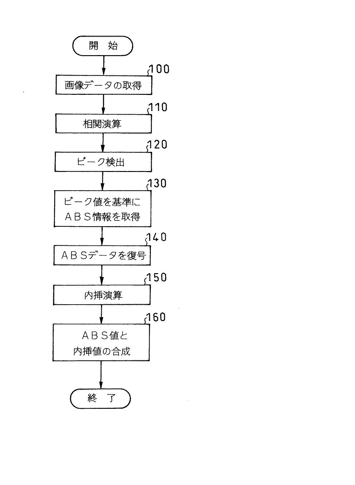
以下、図7に示すフローチャートを参照して全体の処理手順を説明する。 The overall processing procedure will be described below with reference to the flowchart shown in FIG.
まず、ステップ100で、前記ノイズフィルタ・増幅回路32、A/D変換器34及び信号補正回路36を介して、画像データを取得する。
First, in
次いでステップ110で、前記相関演算回路38により、図8に示す如く、相関演算を行なう。なお、図8では差を用いる差分法を示したが、積を用いる掛け算法を使用しても良い。
Next, at
次いでステップ120で、得られた画像相関値から、図9に示す如く、逆凸状に現われるピークを検出し、そのピーク付近の相関値を利用して、図10(特許文献5の図12に対応)に示す如く、真のピークを内挿演算する。内挿演算には、特許文献5に記載されている方法や、最小二乗法による多項式のフィッティングによる推定を用いることができる。又、このピーク検出により、ABSコードのデコード開始位置を精度良く決めることができる。なお、相関演算は画面全域で行なう必要は無く、ピークを検出し、内挿のために必要な最低限のみ求めれば、計算を終了して計算量を削減することができる。スタートビットは、図3に示した如く、「1」、「0」のどちらのパターンにも存在するので、擬似乱数列の値によって、画像相関を行なう範囲が大きく増加したり、検出できなくなったりすることがない。
Next, in
次いでステップ130で、前記ABS演算回路40により、ピーク位置を基準にABS情報を取得し、ステップ140で、ABSデータを復号する。
Next, in
次いで、ステップ150で内挿演算を行なった後、ステップ160で、前記位置合成回路42により、光学系の倍率を考慮してABS位値と内挿位値を合成すれば、求める絶対位置を算出することができる。
Next, after performing an interpolation operation in
以下、具体的な合成演算の方法の例を図11を参照して説明する。 Hereinafter, a specific example of the composition calculation method will be described with reference to FIG.
まず、M系列のデータをデコード開始した位置XABSを求める。この位置は単なるピク
セル番号ではなく、サブピクセル以下の値が必要である。
First, a position X ABS where decoding of M-sequence data is started is obtained. This position is not just a pixel number, but a value less than or equal to a subpixel is required.
XABS=Xp−Spitch・n …(1)
Xp:内挿演算のピーク検出位置
Spitch:スケールの1フレーム長、実施例では120μm
n:内挿演算位置からABSコード開始位置までのフレーム数
X ABS = X p −S pitch · n (1)
X p : Peak detection position of interpolation calculation S pitch : One frame length of the scale, 120 μm in the embodiment
n: Number of frames from the interpolation calculation position to the ABS code start position
次に原点位置からのABSフレーム番号PABSを光学倍率Soptを加味して加えると、求める位置Xは、次式で得られる。 Then the addition by adding the ABS frame number P ABS optical power S opt from the origin position, a position X to obtain can be obtained by the following equation.
X=(PABS・Spitch−XABS)/Sopt+X0 …(2)
PABS:デコードされたABSフレーム番号
XABS:M系列ABSコードのデコード開始位置
Sopt:光学倍率
X0:オフセット調整値
X = (P ABS · S pitch −X ABS ) / S opt + X 0 (2)
P ABS : Decoded ABS frame number X ABS : Decoding start position of M series ABS code S opt : Optical magnification X 0 : Offset adjustment value
これらの手法により、全長を比較する場合に比べて、計算量の大幅な削減が可能となり、消費電力を大きく低減することができる。 By these methods, the amount of calculation can be greatly reduced as compared with the case where the total lengths are compared, and the power consumption can be greatly reduced.
本参考形態においては、ピーク検出を、画像の歪みの少ない中心部分のみで行なっているので、少ない計算負荷で高精度の測定を行なうことができる。なお、両端の2個所で行なって、ミスアライメントの影響を受け難くしたり、あるいは、全体で行なうことも可能である。 In this reference embodiment, the peak detection, so is performed only a small central portion of the image distortion, it is possible to perform highly accurate measurement with a small calculation load. Note that it can be performed at two locations on both ends to make it less susceptible to misalignment or as a whole.
なお、前記参考形態の変調ビットパターンは、1フレームで1ビットの信号しか表現していないため、撮像範囲と製造上の制限から来るスケールの最小幅の関係から、表現できる絶対位置範囲が数百mmに限られていた。例えば、フレーム長が120μm、マーク最小幅が20μm、撮像範囲が1.44mm(イメージセンサで12フレームを一度に撮影)としたとき、表現可能な絶対位置範囲は約245mmである。又、リニアスケール等の用途では、ゴミやノイズによるビットの読み取り誤りの検出や訂正を行なうため、更に多くの情報を付加しなければならず、リニアスケールへの適用は難しかった。 Since the modulation bit pattern of the reference embodiment represents only a 1-bit signal in one frame, there are several hundred absolute position ranges that can be represented from the relationship between the imaging range and the minimum scale width resulting from manufacturing limitations. It was limited to mm. For example, when the frame length is 120 μm, the minimum mark width is 20 μm, and the imaging range is 1.44 mm (12 frames are captured at a time by the image sensor), the absolute position range that can be expressed is about 245 mm. Further, in applications such as a linear scale, in order to detect and correct bit reading errors due to dust and noise, more information must be added, making it difficult to apply to a linear scale.
次に、表現可能な絶対位置範囲を広げて、リニアスケールにも適用可能とした、本発明の第1実施形態を詳細に説明する。 Next, the first embodiment of the present invention, which can be applied to a linear scale by expanding the range of absolute position that can be expressed, will be described in detail.
本実施形態は、参考形態と同じ装置構成において、スケールデザインを改良したものである。 In the present embodiment, the scale design is improved in the same apparatus configuration as that of the reference embodiment.
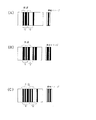
即ち、絶対位置を示すためのコードとして、1つのフレームにベクトル値を割り当てて多値化し、複数のフレームでベクトルの全ての値を表現するようなコードを用いる。図12は、2ビットの値を持つフレーム、図13は、3ビットの値を持つフレーム、図14は、4ビットの値を持つフレームの例を示している。 That is, as a code for indicating the absolute position, a code that assigns a vector value to one frame to be multi-valued and expresses all values of the vector in a plurality of frames is used. 12 shows a frame having a 2-bit value, FIG. 13 shows a frame having a 3-bit value, and FIG. 14 shows an example of a frame having a 4-bit value.
いずれの次元のフレームの場合も、各ビットパターンは、同一の幅であり、共通する部分を持つ。図12、図13、図14の例では、ビットパターンの左端付近が、黒から白に変化する共通イメージ(参照イメージと称する)となっている。又、共通する部分以外のイメージには、参照イメージと同じ部分があってはならない。そして、参考形態と同様に、スケール上に擬似乱数を測長方向に配置するが、このとき、擬似乱数列を、使用するベクトルの次元で区切り、そのベクトル値に該当するフレームを割り当てて、スケールパターンとする。擬似乱数としては、M系列、gold系列等を用いることができる。なお、第1実施形態によるスケールデザインは、図12〜図14に示したものに限定されず、他にも多くの変形例が可能である。又、ベクトル値も図に示した、上から4個(図12)、8個(図13)、16個(図14)に限定されず、任意の組合せをデコードに用い、残りの予備の部分を誤り訂正等に使うことができる。ビット長も、5ビット以上にしても良い。 In any dimension frame, each bit pattern has the same width and a common part. In the examples of FIGS. 12, 13, and 14, the left end of the bit pattern is a common image (referred to as a reference image) that changes from black to white. Also, the image other than the common part must not have the same part as the reference image. Then, as in the reference embodiment, pseudo random numbers are arranged in the length measurement direction on the scale. A pattern. As the pseudo random number, an M series, a gold series, or the like can be used. In addition, the scale design by 1st Embodiment is not limited to what was shown in FIGS. 12-14, Many other modifications are possible. Also, the vector values are not limited to four (FIG. 12), eight (FIG. 13), and sixteen (FIG. 14) from the top as shown in the figure, and any combination is used for decoding, and the remaining spare part. Can be used for error correction. The bit length may be 5 bits or more.
例として、スタートビットに当たる最小線幅を20μm、その他の線幅を20μm×Nとしたときに、それぞれのベクトルの次元数M別の表現に必要なフレーム長Lを表1に示す。 As an example, Table 1 shows the frame length L necessary for expressing each vector by the number of dimensions M when the minimum line width corresponding to the start bit is 20 μm and the other line widths are 20 μm × N.
又、それぞれの例において、表現できる絶対位置範囲Pは、次の関係式で示される。 In each example, the absolute position range P that can be expressed is represented by the following relational expression.
P=L*2^(N−1) …(3)
N={ROUND(F/L)−1}*M …(4)
※ROUND()は丸めの意味
L:1フレーム長
N:撮像範囲内のビット数
F:イメージセンサ等を用いたときの実体の撮像範囲
M:ベクトル次元数(多値化数)
P = L * 2 ^ (N-1) (3)
N = {ROUND (F / L) -1} * M (4)
* ROUND () means rounding L: 1 frame length N: Number of bits in the imaging range F: Actual imaging range when using an image sensor, etc. M: Number of vector dimensions (multi-valued number)
例えばベクトル次元をM=3として、1フレーム長L=160μm、撮像範囲F=1.44mmとした場合、全てのビットで絶対位置を表現すると、表現可能な絶対位置範囲Pは、次のようになる。 For example, assuming that the vector dimension is M = 3, one frame length L = 160 μm, and imaging range F = 1.44 mm, the absolute position range P that can be expressed is expressed as follows when the absolute position is expressed by all bits: Become.
P=0.160*2^{(ROUND(1.44/0.16)−1)*3−1}
=1342177[mm] …(5)
P = 0.160 * 2 ^ {(ROUND (1.44 / 0.16) -1) * 3-1}
= 1342177 [mm] (5)
次元Mが4の場合、同様な計算により24159191[mm]となる。結果を表1の表現可能な絶対位置範囲Pに示す。 When the dimension M is 4, 24159191 [mm] is obtained by the same calculation. The results are shown in the absolute position range P that can be expressed in Table 1.
これらの結果から、参考形態と同様の光学系、マーク最小ピッチ幅を用いた場合でも、ベクトル化(多値化)により実用上十分な範囲の絶対位置を示すことができることが分かる。 From these results, it can be seen that even when the same optical system and minimum mark pitch width as those in the reference embodiment are used, the absolute position in a practically sufficient range can be shown by vectorization (multi-value).
又、これらのビット情報に誤り検出符号を付加することで、ゴミやノイズ等によるビット読み取りミスにも対応できる。 Further, by adding an error detection code to these bit information, it is possible to cope with a bit reading error due to dust or noise.
図15に、このベクトル化(多値化)方法を使用して、スケールを設計する方法を示す。まず、参考形態と同様にM系列を用いて、必要な長さの擬似乱数列を作成する。図15に示したように3ビットの多値化を行なう場合には、求められた擬似乱数列を3ビット毎に区切り、各区切り毎に該当するデザインを割り当てていき、全ての数列にビットパターンを割り当てれば終了となる。 FIG. 15 shows a method of designing a scale using this vectorization (multi-value) method. First, a pseudo-random number sequence having a required length is created using the M sequence as in the reference embodiment. As shown in FIG. 15, when 3-bit multi-value processing is performed, the obtained pseudo-random number sequence is divided every 3 bits, and a design corresponding to each division is assigned. If you assign, it ends.
デコードする場合は、参考形態と同様に、画像相関を利用してスタートビット付近の参照イメージを検出し、1フレーム毎にビットパターンを切り出し、ビットパターン毎のベクトル値を取り出し、擬似乱数列として合成すればよい。画像相関によるサブピクセル以下の値の演算も、参考形態と同様に行なうことができる。 When decoding, as in the reference embodiment, the reference image near the start bit is detected using image correlation, the bit pattern is extracted for each frame, the vector value for each bit pattern is extracted, and synthesized as a pseudo-random number sequence do it. The calculation of the value below the subpixel by the image correlation can be performed in the same manner as in the reference embodiment.
この第1実施形態によれば、参考形態より広範囲なABS位置を表現できるので、リニアエンコーダ等、広範囲のアブソリュートエンコーダを供給できる。又、誤り訂正符号を付加することにより、信頼性の高いエンコーダを供給することができる。 According to the first embodiment, since a wider range of ABS positions can be expressed than in the reference embodiment, a wide range of absolute encoders such as a linear encoder can be supplied. Also, by adding an error correction code, a highly reliable encoder can be supplied.
なお、本エンコーダ方式は、1次元の受光素子アレイだけでなく、汎用で安価な2次元の受光素子マトリックスを用いた場合にも応用できる。 The encoder system can be applied not only to a one-dimensional light receiving element array but also to a general-purpose and inexpensive two-dimensional light receiving element matrix.
前記実施形態においては、本発明が、アブソリュートエンコーダに適用されていたが、本発明の適用対象はこれに限定されず、インクリメンタルエンコーダにも同様に適用できる。 In the above-described embodiment, the present invention is applied to an absolute encoder. However, the application target of the present invention is not limited to this, and can be applied to an incremental encoder as well.
10…スケール
20…検出器
22…発光素子
24…レンズ
26…受光素子アレイ
30…信号処理装置
32…ノイズフィルタ・増幅回路
34…A/D変換器
36…信号補正回路
38…相関演算回路
40…ABS演算回路
42…位置合成回路
DESCRIPTION OF
Claims (7)
前記ビットパターンが、共通の部分とベクトル値が順次割り当てられた部分とでなるフレームパターンを持つように変調されると共に、
前記ベクトル値が、擬似乱数列を、使用するベクトル値の次元で区切ったものとされていることを特徴とする光電式エンコーダ。 In a photoelectric encoder that acquires an image of the bit pattern on the scale with a detector and detects the relative displacement between the scale and the detector,
The bit pattern is modulated to have a frame pattern common parts and the vector value is in the order allocated portion Rutotomoni,
The photoelectric encoder is characterized in that the vector value is obtained by dividing a pseudo random number sequence by the dimension of a vector value to be used .
Priority Applications (1)
| Application Number | Priority Date | Filing Date | Title |
|---|---|---|---|
| JP2005293228A JP4846331B2 (en) | 2005-01-18 | 2005-10-06 | Photoelectric encoder and its scale |
Applications Claiming Priority (3)
| Application Number | Priority Date | Filing Date | Title |
|---|---|---|---|
| JP2005010621 | 2005-01-18 | ||
| JP2005010621 | 2005-01-18 | ||
| JP2005293228A JP4846331B2 (en) | 2005-01-18 | 2005-10-06 | Photoelectric encoder and its scale |
Publications (2)
| Publication Number | Publication Date |
|---|---|
| JP2006226987A JP2006226987A (en) | 2006-08-31 |
| JP4846331B2 true JP4846331B2 (en) | 2011-12-28 |
Family
ID=36988471
Family Applications (1)
| Application Number | Title | Priority Date | Filing Date |
|---|---|---|---|
| JP2005293228A Active JP4846331B2 (en) | 2005-01-18 | 2005-10-06 | Photoelectric encoder and its scale |
Country Status (1)
| Country | Link |
|---|---|
| JP (1) | JP4846331B2 (en) |
Cited By (1)
| Publication number | Priority date | Publication date | Assignee | Title |
|---|---|---|---|---|
| US9651403B2 (en) | 2012-05-15 | 2017-05-16 | Korea Research Institute Of Standards And Science | Absolute position measurement method, absolute position measurement apparatus and scale |
Families Citing this family (14)
| Publication number | Priority date | Publication date | Assignee | Title |
|---|---|---|---|---|
| JP4989313B2 (en) * | 2007-05-28 | 2012-08-01 | 株式会社トプコン | Absolute angle calculation device |
| JP5203024B2 (en) * | 2008-04-15 | 2013-06-05 | 株式会社ミツトヨ | Absolute position measuring encoder |
| JP5011201B2 (en) * | 2008-05-01 | 2012-08-29 | 株式会社ミツトヨ | Absolute position measuring encoder |
| JP5103267B2 (en) * | 2008-05-13 | 2012-12-19 | 株式会社ミツトヨ | Absolute position measuring encoder |
| GB0909724D0 (en) | 2009-06-05 | 2009-07-22 | Renishaw Plc | Position measurement encoder and method of operation |
| JP2011058988A (en) * | 2009-09-11 | 2011-03-24 | Mitsutoyo Corp | Displacement detector, displacement detection method, and displacement detecting program |
| JP5381754B2 (en) * | 2010-01-29 | 2014-01-08 | 株式会社ニコン | Encoder |
| JP5560873B2 (en) * | 2010-04-21 | 2014-07-30 | 株式会社ニコン | Encoder and encoder position detection method |
| JP5379761B2 (en) * | 2010-08-06 | 2013-12-25 | キヤノン株式会社 | Absolute encoder |
| JP5832088B2 (en) * | 2010-12-15 | 2015-12-16 | キヤノン株式会社 | Rotary encoder |
| KR101341804B1 (en) | 2012-05-15 | 2013-12-16 | 한국표준과학연구원 | Absolute Position Measuring Method, Absolute Position Measuring Apparatus, and Scale |
| JP6634249B2 (en) * | 2015-09-14 | 2020-01-22 | 株式会社ミツトヨ | Absolute position detection type photoelectric encoder |
| JP5974154B2 (en) * | 2015-10-28 | 2016-08-23 | キヤノン株式会社 | Rotary encoder |
| JP6744066B2 (en) * | 2016-03-25 | 2020-08-19 | 株式会社ミツトヨ | Photoelectric encoder |
Family Cites Families (4)
| Publication number | Priority date | Publication date | Assignee | Title |
|---|---|---|---|---|
| JPS5764893A (en) * | 1980-10-08 | 1982-04-20 | Tokyo Optical | Encoder |
| JPH0663740B2 (en) * | 1987-09-28 | 1994-08-22 | 住友重機械工業株式会社 | Alignment mark position detection method |
| JPH0526688A (en) * | 1991-07-19 | 1993-02-02 | Furuno Electric Co Ltd | Rotary encoder |
| US6304190B1 (en) * | 1997-06-28 | 2001-10-16 | Leopold Kostal Gmbh & Co. Kg | Method for determining the absolute angular position of the steering wheel of a motor vehicle, and optoelecronic steering angle sensor |
-
2005
- 2005-10-06 JP JP2005293228A patent/JP4846331B2/en active Active
Cited By (1)
| Publication number | Priority date | Publication date | Assignee | Title |
|---|---|---|---|---|
| US9651403B2 (en) | 2012-05-15 | 2017-05-16 | Korea Research Institute Of Standards And Science | Absolute position measurement method, absolute position measurement apparatus and scale |
Also Published As
| Publication number | Publication date |
|---|---|
| JP2006226987A (en) | 2006-08-31 |
Similar Documents
| Publication | Publication Date | Title |
|---|---|---|
| JP4846331B2 (en) | Photoelectric encoder and its scale | |
| JP4885630B2 (en) | Two-dimensional encoder and its scale | |
| EP2414782B1 (en) | A one-dimension position encoder | |
| US8110792B2 (en) | Absolute position length measurement type encoder | |
| TWI519766B (en) | Method and apparatus for determining position | |
| CN100516780C (en) | Absolute encoder employing concatenated, multi-bit, interpolated sub-encoders | |
| KR102008632B1 (en) | Absolute encoder | |
| US9651403B2 (en) | Absolute position measurement method, absolute position measurement apparatus and scale | |
| CN102095439B (en) | Single-code-channel absolute-position encoding method, decoding method and measuring device | |
| US20110316527A1 (en) | Encoder readhead | |
| US7565256B2 (en) | Displacement detecting encoder | |
| US20050072016A1 (en) | Position measuring device | |
| EP2878928B1 (en) | Absolute encoder, signal processing method, program, driving apparatus, and industrial machine | |
| CN102003976B (en) | Single-code channel absolute position coding method, decoding method and measuring device | |
| GB2353421A (en) | Determining the position between two parts which move relative to each other | |
| CN112585645A (en) | Multi-axis position sensing system | |
| US20150377654A1 (en) | Method and System for Estimating Positions Using Absolute Encoders | |
| US9322675B2 (en) | Absolute encoder and method of obtaining absolute position by a plurality of quantized data based on a plurality of extrema | |
| JPH0335111A (en) | Absolute position detecting device | |
| KR102041890B1 (en) | Absolute Position Measuring Method, Absolute Position Measuring Apparatus, and Colour Scale | |
| WO2017043249A1 (en) | Method and apparatus for determining position on scale | |
| CN113029002B (en) | Linear displacement measuring device and method | |
| CN115597638A (en) | Absolute angle measuring method and photoelectric encoder | |
| JPH1098584A (en) | Measurement device for picture element position error or scanning speed of original |
Legal Events
| Date | Code | Title | Description |
|---|---|---|---|
| A621 | Written request for application examination |
Free format text: JAPANESE INTERMEDIATE CODE: A621 Effective date: 20080904 |
|
| A977 | Report on retrieval |
Free format text: JAPANESE INTERMEDIATE CODE: A971007 Effective date: 20110223 |
|
| A131 | Notification of reasons for refusal |
Free format text: JAPANESE INTERMEDIATE CODE: A131 Effective date: 20110607 |
|
| A521 | Written amendment |
Free format text: JAPANESE INTERMEDIATE CODE: A523 Effective date: 20110726 |
|
| TRDD | Decision of grant or rejection written | ||
| A01 | Written decision to grant a patent or to grant a registration (utility model) |
Free format text: JAPANESE INTERMEDIATE CODE: A01 Effective date: 20111011 |
|
| A01 | Written decision to grant a patent or to grant a registration (utility model) |
Free format text: JAPANESE INTERMEDIATE CODE: A01 |
|
| A61 | First payment of annual fees (during grant procedure) |
Free format text: JAPANESE INTERMEDIATE CODE: A61 Effective date: 20111012 |
|
| FPAY | Renewal fee payment (event date is renewal date of database) |
Free format text: PAYMENT UNTIL: 20141021 Year of fee payment: 3 |
|
| R150 | Certificate of patent or registration of utility model |
Free format text: JAPANESE INTERMEDIATE CODE: R150 Ref document number: 4846331 Country of ref document: JP Free format text: JAPANESE INTERMEDIATE CODE: R150 |
|
| R250 | Receipt of annual fees |
Free format text: JAPANESE INTERMEDIATE CODE: R250 |
|
| R250 | Receipt of annual fees |
Free format text: JAPANESE INTERMEDIATE CODE: R250 |
|
| R250 | Receipt of annual fees |
Free format text: JAPANESE INTERMEDIATE CODE: R250 |