JP4840967B2 - Imaging apparatus, image processing method, program, and storage medium - Google Patents
Imaging apparatus, image processing method, program, and storage medium Download PDFInfo
- Publication number
- JP4840967B2 JP4840967B2 JP2005347931A JP2005347931A JP4840967B2 JP 4840967 B2 JP4840967 B2 JP 4840967B2 JP 2005347931 A JP2005347931 A JP 2005347931A JP 2005347931 A JP2005347931 A JP 2005347931A JP 4840967 B2 JP4840967 B2 JP 4840967B2
- Authority
- JP
- Japan
- Prior art keywords
- data
- image
- component data
- color
- luminance component
- Prior art date
- Legal status (The legal status is an assumption and is not a legal conclusion. Google has not performed a legal analysis and makes no representation as to the accuracy of the status listed.)
- Expired - Fee Related
Links
- 238000003384 imaging method Methods 0.000 title claims description 16
- 238000003672 processing method Methods 0.000 title claims description 5
- 238000006243 chemical reaction Methods 0.000 claims description 31
- 230000006835 compression Effects 0.000 claims description 28
- 238000007906 compression Methods 0.000 claims description 28
- 238000000034 method Methods 0.000 claims description 10
- 230000008707 rearrangement Effects 0.000 claims description 9
- 238000000926 separation method Methods 0.000 claims description 7
- 230000002441 reversible effect Effects 0.000 claims description 6
- 230000003287 optical effect Effects 0.000 claims description 4
- 230000002427 irreversible effect Effects 0.000 claims description 2
- 230000006870 function Effects 0.000 description 10
- 238000010586 diagram Methods 0.000 description 7
- 230000006866 deterioration Effects 0.000 description 6
- 230000002829 reductive effect Effects 0.000 description 6
- 230000000873 masking effect Effects 0.000 description 4
- 239000003086 colorant Substances 0.000 description 3
- 238000003491 array Methods 0.000 description 2
- 230000000875 corresponding effect Effects 0.000 description 2
- 230000000694 effects Effects 0.000 description 2
- 239000004973 liquid crystal related substance Substances 0.000 description 2
- 239000011159 matrix material Substances 0.000 description 2
- 238000005457 optimization Methods 0.000 description 2
- 230000015556 catabolic process Effects 0.000 description 1
- 230000002596 correlated effect Effects 0.000 description 1
- 238000006731 degradation reaction Methods 0.000 description 1
- 238000003825 pressing Methods 0.000 description 1
- 230000000717 retained effect Effects 0.000 description 1
- 238000005070 sampling Methods 0.000 description 1
- WFKWXMTUELFFGS-UHFFFAOYSA-N tungsten Chemical compound [W] WFKWXMTUELFFGS-UHFFFAOYSA-N 0.000 description 1
- 229910052721 tungsten Inorganic materials 0.000 description 1
- 239000010937 tungsten Substances 0.000 description 1
- 230000004304 visual acuity Effects 0.000 description 1
Images


Classifications
-
- H—ELECTRICITY
- H04—ELECTRIC COMMUNICATION TECHNIQUE
- H04N—PICTORIAL COMMUNICATION, e.g. TELEVISION
- H04N1/00—Scanning, transmission or reproduction of documents or the like, e.g. facsimile transmission; Details thereof
- H04N1/40—Picture signal circuits
- H04N1/40068—Modification of image resolution, i.e. determining the values of picture elements at new relative positions
-
- H—ELECTRICITY
- H04—ELECTRIC COMMUNICATION TECHNIQUE
- H04N—PICTORIAL COMMUNICATION, e.g. TELEVISION
- H04N1/00—Scanning, transmission or reproduction of documents or the like, e.g. facsimile transmission; Details thereof
- H04N1/46—Colour picture communication systems
- H04N1/64—Systems for the transmission or the storage of the colour picture signal; Details therefor, e.g. coding or decoding means therefor
- H04N1/646—Transmitting or storing colour television type signals, e.g. PAL, Lab; Their conversion into additive or subtractive colour signals or vice versa therefor
-
- H—ELECTRICITY
- H04—ELECTRIC COMMUNICATION TECHNIQUE
- H04N—PICTORIAL COMMUNICATION, e.g. TELEVISION
- H04N23/00—Cameras or camera modules comprising electronic image sensors; Control thereof
- H04N23/80—Camera processing pipelines; Components thereof
- H04N23/84—Camera processing pipelines; Components thereof for processing colour signals
- H04N23/843—Demosaicing, e.g. interpolating colour pixel values
-
- H—ELECTRICITY
- H04—ELECTRIC COMMUNICATION TECHNIQUE
- H04N—PICTORIAL COMMUNICATION, e.g. TELEVISION
- H04N25/00—Circuitry of solid-state image sensors [SSIS]; Control thereof
- H04N25/10—Circuitry of solid-state image sensors [SSIS]; Control thereof for transforming different wavelengths into image signals
- H04N25/11—Arrangement of colour filter arrays [CFA]; Filter mosaics
- H04N25/13—Arrangement of colour filter arrays [CFA]; Filter mosaics characterised by the spectral characteristics of the filter elements
- H04N25/134—Arrangement of colour filter arrays [CFA]; Filter mosaics characterised by the spectral characteristics of the filter elements based on three different wavelength filter elements
-
- H—ELECTRICITY
- H04—ELECTRIC COMMUNICATION TECHNIQUE
- H04N—PICTORIAL COMMUNICATION, e.g. TELEVISION
- H04N2209/00—Details of colour television systems
- H04N2209/04—Picture signal generators
- H04N2209/041—Picture signal generators using solid-state devices
- H04N2209/042—Picture signal generators using solid-state devices having a single pick-up sensor
- H04N2209/045—Picture signal generators using solid-state devices having a single pick-up sensor using mosaic colour filter
- H04N2209/046—Colour interpolation to calculate the missing colour values
Landscapes
- Engineering & Computer Science (AREA)
- Multimedia (AREA)
- Signal Processing (AREA)
- Physics & Mathematics (AREA)
- Spectroscopy & Molecular Physics (AREA)
- Compression Of Band Width Or Redundancy In Fax (AREA)
- Color Image Communication Systems (AREA)
- Image Processing (AREA)
- Editing Of Facsimile Originals (AREA)
- Facsimile Image Signal Circuits (AREA)
- Studio Devices (AREA)
- Color Television Image Signal Generators (AREA)
- Television Signal Processing For Recording (AREA)
Description
本発明は、撮像した画像データをリサイズ(解像度変換)する技術に関するものである。 The present invention relates to a technique for resizing (resolution conversion) captured image data.
従来より、デジタルカメラの生成するファイルには2種類あることが一般によく知られている。1つは、デジタルカメラ内で画像処理が行われた後の画像で、JPEGもしくは、TIFFといった形式の汎用的な画像表示ビューワで開くことが出来るファイル形式である。もう1つは、撮像条件に関する画像処理を施さずに撮像時の2次元配列のセンサ出力をそのまま記録したRAW形式と呼ばれるファイル形式である。RAW形式のファイルの特徴は、カメラ外部のアプリケーションで撮像条件に関する画像処理を行うため、さまざまなパラメータを撮影時とは異なる設定にして再現像することが出来ることである(例えば、特許文献1を参照)。 Conventionally, it is generally well known that there are two types of files generated by a digital camera. One is a file format that can be opened by a general-purpose image display viewer in a format such as JPEG or TIFF, after being subjected to image processing in the digital camera. The other is a file format called a RAW format in which the sensor output of the two-dimensional array at the time of imaging is recorded as it is without performing image processing relating to the imaging conditions. A feature of the RAW format file is that image processing relating to imaging conditions is performed by an application outside the camera, so that various parameters can be re-developed with settings different from those at the time of shooting (for example, see Patent Document 1). reference).
しかしながら、RAW形式の画像ファイルは、可逆圧縮したデータであるため、一般的にJPEG形式やTIFF形式のファイルよりファイルサイズが大きくなってしまう。JPEG圧縮したくない場合や、光源の状態の推測が難しく、後で調整したい場合などには、RAW形式のファイルが有効である。 However, since the RAW format image file is reversible compressed data, the file size is generally larger than that of a JPEG format or TIFF format file. When JPEG compression is not desired, or when it is difficult to estimate the state of the light source and adjustment is desired later, a RAW file is effective.
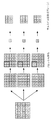
なお、従来のデジタルカメラには、1回の撮像で、RAW形式の画像データとJPEG形式の画像データの双方を生成するものがあり、図8は、RAW形式の画像データとJPEG形式の画像データを生成するブロック構成を示す図である。 Some conventional digital cameras generate both RAW-format image data and JPEG-format image data in one imaging operation. FIG. 8 shows RAW-format image data and JPEG-format image data. It is a figure which shows the block structure which produces | generates.
撮像素子から出力されA/D変換されたデジタル画像データには、まずホワイトバランス処理回路7b1においてホワイトバランス係数が掛けられ、ホワイトバランスがとられる。ホワイトバランスがとられた画像データは、色補間回路7b2において色補間され、R(赤)G(緑)B(青)が格子状に配列されたパターン(例えばベイヤー配列)のデータから、RGBの3プレーンが作り出される。次に、RGBの3プレーンが揃った画像データは、マスキング処理回路7b3において、例えば、3×3のマトリクス演算等で色の最適化が行なわれ、ガンマ変換回路7b4でガンマ変換される。次に、ガンマ変換された画像データは、YUV変換回路7b5において、RGB信号から、偽色処理やエッジ強調を行なうためのYUVという輝度成分と色差成分の信号に変換される。 The digital image data output from the image sensor and subjected to A / D conversion is first multiplied by a white balance coefficient in the white balance processing circuit 7b1 to obtain white balance. The white balance image data is color-interpolated by the color interpolation circuit 7b2, and R (red), G (green), and B (blue) are arranged in a grid pattern (for example, Bayer array) from RGB data. Three planes are created. Next, the image data including the three RGB planes is subjected to color optimization by, for example, 3 × 3 matrix calculation in the masking processing circuit 7b3, and gamma-converted by the gamma conversion circuit 7b4. Next, the gamma-converted image data is converted from RGB signals into YUV luminance component and color difference component signals for false color processing and edge enhancement in the YUV conversion circuit 7b5.
通常のJPEG画像を作成する場合は、YUV変換された信号の内の輝度成分であるY信号は、エッジ強調回路7b9でエッジ強調される。また、YUV変換された信号の内の色差成分であるUV信号は、メディアンフィルタ回路7b8でメディアンフィルタをかけられる。最後に、整ったYUVのデータはJPEG圧縮回路7eでJPEG圧縮される。
In the case of creating a normal JPEG image, the Y signal, which is a luminance component in the YUV converted signal, is edge enhanced by the edge enhancement circuit 7b9. The UV signal, which is a color difference component in the YUV converted signal, is subjected to a median filter by a median filter circuit 7b8. Finally, the prepared YUV data is JPEG compressed by the
一方、デジタル画像データは、ホワイトバランス回路以降の回路を通らずに、直接可逆圧縮回路7dにも供給され、可逆圧縮が行なわれる。これにより、RAW形式の画像データが作られる。
しかしながら、RAW形式のファイルは、図4に示すように、常にセンサーの画素数分のデータを持つため、画像の用途に応じて、簡単にはファイルサイズを小さくして使うことが出来ない。デジタルカメラの画素数が増えていけばRAW形式のファイルのサイズも増大するが、センサーの2次元配列は、ベイヤー配列と呼ばれるRGBの千鳥格子の並びが多く、そのままではRGBの3プレーンのデータのようには画素数を減らすことが出来ない。さらに、単純にベイヤー配列のままリサイズを行い、同じ配列に戻そうとすると、現像後のモアレや、偽色がリサイズ前に比べて多くなり、画質を劣化させてしまう。 However, as shown in FIG. 4, a RAW format file always has data for the number of pixels of the sensor, and therefore cannot be used with a reduced file size according to the purpose of the image. If the number of pixels of the digital camera increases, the size of the RAW file will also increase, but the two-dimensional sensor array has many RGB houndstooth arrays called Bayer arrays, and RGB 3-plane data as it is It is not possible to reduce the number of pixels. Further, if resizing is simply performed while maintaining the Bayer array, and the image is returned to the same array, moire after development and false colors increase compared to before resizing, and the image quality deteriorates.
従って、本発明は上述した課題に鑑みてなされたものであり、その目的は、リサイズした画像を得るに当たり、リサイズした画像の偽色やモアレ等の画質の劣化を低減することである。 Accordingly, the present invention has been made in view of the above-described problems, and an object thereof is to reduce image quality deterioration such as false color and moire of the resized image when obtaining the resized image.
上述した課題を解決し、目的を達成するために、本発明に係わる撮像装置は、R,G,及びBのベイヤー配列のカラーフィルタで分離される光学像をR,G,及びBの電気信号に変換する撮像素子と、前記撮像素子から出力されたR,G,及びBの画像信号をデジタル画像データに変換するA/D変換手段と、前記R,G,及びBのデジタル画像データを色補間する色補間手段と、前記色補間手段により色補間されたデジタル画像データを輝度成分データと色差成分データとに分離する分離手段と、前記分離手段によって分離された輝度成分データと色差成分データの画像サイズを変換する画像サイズ変換手段と、前記画像サイズ変換手段によって変換された輝度成分データと色差成分データとのタイミングを調整して前記ベイヤー配列のGの位置に前記輝度成分データを再配列し前記ベイヤー配列のRとBの位置に前記色差成分データを再配列する再配列手段と、前記再配列手段により再配列された輝度成分データと色差成分データを圧縮して圧縮データを生成する圧縮手段と、を具備することを特徴とする。 In order to solve the above-described problems and achieve the object, an imaging apparatus according to the present invention converts an optical image separated by R, G, and B Bayer array color filters into R, G, and B electrical signals. An image sensor for converting to R, G and B image signals output from the image sensor , A / D conversion means for converting the image signals to digital image data , and R, G and B digital image data for color a color interpolation means for interpolating, separating means and the luminance component data and chrominance component data separated by the separating means for separating the digital image data subjected to color interpolated by the color interpolation means into a luminance component data and chrominance component data Image size conversion means for converting the image size of the image, and the timing of the luminance component data and the color difference component data converted by the image size conversion means to adjust G of the Bayer array Rearrangement means for rearranging the luminance component data at the position of R and rearranging the color difference component data at the positions of R and B in the Bayer arrangement, and the luminance component data and the color difference component data rearranged by the rearrangement means Compression means for generating compressed data by compressing.
また、本発明に係わる画像処理方法は、R,G,及びBのベイヤー配列のカラーフィルタで分離される光学像をR,G,及びBの電気信号に変換する撮像素子から出力されたR,G,及びBの画像信号をデジタル画像データに変換するA/D変換工程と、前記R,G,及びBのデジタル画像データを色補間する色補間工程と、前記色補間工程において色補間されたデジタル画像データを輝度成分データと色差成分データとに分離する分離工程と、前記分離工程において分離された輝度成分データと色差成分データの画像サイズを変換する画像サイズ変換工程と、前記画像サイズ変換工程において変換された輝度成分データと色差成分データとのタイミングを調整して前記ベイヤー配列のGの位置に前記輝度成分データを再配列し前記ベイヤー配列のRとBの位置に前記色差成分データを再配列する再配列工程と、前記再配列工程において再配列された輝度成分データと色差成分データを圧縮する圧縮工程と、を具備することを特徴とする。 The image processing method according to the present invention also includes an R, G, and B Bayer array color filter that outputs an R, G, and B electrical signal output from an image sensor that converts R, G, and B electrical signals . A / D conversion step for converting G and B image signals into digital image data, a color interpolation step for color interpolation of the R, G and B digital image data, and color interpolation in the color interpolation step Separation step for separating digital image data into luminance component data and color difference component data, an image size conversion step for converting the image size of the luminance component data and color difference component data separated in the separation step, and the image size conversion step Adjusting the timing of the luminance component data and the color difference component data converted in step B and rearranging the luminance component data at the position G in the Bayer array, Characterized by comprising a rearrangement step of rearranging said chrominance component data to the position of the R and B of the sequence, and a compression step of compressing the rearranged luminance component data and chrominance component data in the rearrangement step And
また、本発明に係わるプログラムは、上記の画像処理方法をコンピュータに実行させることを特徴とする。 A program according to the present invention causes a computer to execute the above image processing method.
また、本発明に係わる記憶媒体は、上記のプログラムを記憶したことを特徴とする。 A storage medium according to the present invention stores the above program.
本発明によれば、リサイズした画像を得るに当たり、リサイズした画像の画質の劣化を低減することが可能となる。 According to the present invention, in obtaining a resized image, it is possible to reduce deterioration of the image quality of the resized image.
以下、本発明の好適な実施形態について、添付図面を参照して詳細に説明する。 DESCRIPTION OF EXEMPLARY EMBODIMENTS Hereinafter, preferred embodiments of the invention will be described in detail with reference to the accompanying drawings.
(第1の実施形態)
図1は、本発明の第1の実施形態に係わるデジタルカメラの構成を示すブロック図である。
(First embodiment)
FIG. 1 is a block diagram showing the configuration of a digital camera according to the first embodiment of the present invention.
撮影レンズ1を通ってきた光は、赤外カットフィルタ2及び光学LPF(ローパスフィルタ)3を通過し、撮像素子4(以下CCDと呼ぶ)に結像される。
The light passing through the photographing
CCD4の受光面にはフォトダイオードを用いた光電変換センサが平面的に配置されており、各センサに対して、1色のカラー、例えば、R(赤)・G(緑)・B(青)の原色カラーフィルタが所定の配列で配置されている。なお、本実施形態では、カラーフィルタを用いて光をRGBの3色の成分に分離しているが、例えば、撮像素子を複数枚(例えば3枚)用いて、各撮像素子に対して1色を割り当てる形態も可能である。
Photoelectric conversion sensors using photodiodes are arranged in a plane on the light receiving surface of the
CCD4に結像された光は、各センサにおいて、入射光量に応じた量の電荷に変換される。
The light focused on the
タイミングジェネレータ16が発生する信号は、水平駆動用ドライバ17と垂直駆動用ドライバ18に供給される。そして、水平駆動用ドライバ17と垂直駆動用ドライバ18によりCCD4が駆動され、センサに蓄積された電荷が転送され、その電荷が順次電圧信号に変換されて、CCD4から出力される。
A signal generated by the
CCD4から出力された電圧信号は、相関二重サンプリング回路5(以下CDSと呼ぶ)でサンプリングされ、A/D変換器6でデジタル信号に変換される。
The voltage signal output from the
デジタル信号に変換された画像データは、画像処理IC7に入力され、まず、ホワイトバランスをとるためのデータを算出するWB(ホワイトバランス)回路7aに入力され、WB回路7aからの出力画像データが第1のメモリ8に一旦格納される。
The image data converted into the digital signal is input to the image processing IC 7, and is first input to a WB (white balance)
第1のメモリ8に格納されたデータは、再び画像処理IC7に入力され、3つの画像処理を施される。 The data stored in the first memory 8 is input again to the image processing IC 7 and subjected to three image processes.
まず、デジタル信号に変換された画像データは、そのまま可逆圧縮(ロスレス圧縮)をかける可逆圧縮回路7dに入力される。そして、可逆圧縮回路7dにおいて可逆圧縮され、可逆圧縮されたRAWデータが、CPUバス10に送り出される。
First, the image data converted into a digital signal is input to the
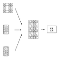
また、デジタル信号に変換された画像データは、RAWサムネイル回路7cにも入力される。RAWサムネイル回路7cでは、例えば図2Aに示すように、RAWデータをブロック内平均し、そこから間引くことによってダウンサンプリングし、元の画像サイズより小さいサムネイル画像データを生成する。RAWサムネイル回路7cから出力されたサムネイル画像データは、CPUバス10に送られる。 The image data converted into a digital signal is also input to the RAW thumbnail circuit 7c. In the RAW thumbnail circuit 7c, for example, as shown in FIG. 2A, the RAW data is averaged in the block, down-sampled by thinning out the average, and thumbnail image data smaller than the original image size is generated. The thumbnail image data output from the RAW thumbnail circuit 7 c is sent to the CPU bus 10.
なお、RAWサムネイルデータを生成する方法には、他に図2Bに示すような方法もある。すなわち、RAWデータにLPF(ローパスフィルタ)をかけた後に間引き、元の画像サイズよりも小さいサムネイル画像データを生成する方法である。 Note that there is another method for generating RAW thumbnail data as shown in FIG. 2B. In other words, this is a method of generating thumbnail image data smaller than the original image size by thinning out the raw data after applying an LPF (low pass filter).
このようにRAWデータを非可逆圧縮せずに間引いてサムネイル画像データを生成することにより、カメラの液晶表示部又はPC(パーソナルコンピュータ)などに表示するサムネイル画像も高画質にすることができる。 In this way, by generating the thumbnail image data by thinning out the RAW data without irreversible compression, the thumbnail image displayed on the liquid crystal display unit of the camera or the PC (personal computer) can also be improved in image quality.
また、デジタル信号に変換された画像データは、画像処理回路7bにも入力される。RGBの画像データは、画像処理回路7bにおいてYCbCr信号に変換されるとともに、ラスタブロック変換されて、JPEG圧縮回路7eでJPEG圧縮される。JPEG圧縮回路7eから出力されたJPEG形式の画像データは、CPUバス10に送られる。
The image data converted into a digital signal is also input to the
さらに、画像処理回路7bの一部の機能を利用してリサイズされた画像データが、可逆圧縮回路7dに送られる。そして、可逆圧縮回路7dの出力が、リサイズされたRAWデータ(Small RAWデータ)としてCPUバス10に送られる。
Further, the resized image data using a part of the function of the
ここで、画像処理回路7bで行わる画像処理についてさらに詳しく説明する。
Here, the image processing performed by the
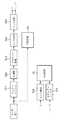
図3は、画像処理回路7bにおける画像処理の概要を示すブロック図である。
FIG. 3 is a block diagram showing an outline of image processing in the
第1のメモリ8から入力されたデジタル画像データは、ホワイトバランス回路7b1に入力される。ホワイトバランス回路7b1では、予めWB回路7aで算出されたデータに基づいてCPU15で計算されたホワイトバランス係数を画像データに掛ける。もしくは、予め設定されているホワイトバランス(例えばデイライト、タングステン、蛍光灯等)の係数を画像データに掛ける。
The digital image data input from the first memory 8 is input to the white balance circuit 7b1. The white balance circuit 7b1 multiplies the image data by the white balance coefficient calculated by the
ホワイトバランス回路7b1でホワイトバランスがとられた画像データは、色補間回路7b2で色補間され、図4に示す様にRGBが格子状に配列されたパターン(例えばベイヤー配列)のデータから、RGBの3プレーンが作り出される。 The image data on which white balance is achieved by the white balance circuit 7b1 is color-interpolated by the color interpolation circuit 7b2, and from the data of the pattern in which RGB is arranged in a grid pattern (for example, Bayer array) as shown in FIG. Three planes are created.
次に、RGBの3プレーンが揃った画像データは、マスキング処理回路7b3において、例えば、式(1)に示すような3×3のマトリクス演算等で色の最適化が行われ、ガンマ変換回路7b4でガンマ変換される。 Next, the image data including the three RGB planes is subjected to color optimization in the masking processing circuit 7b3 by, for example, a 3 × 3 matrix operation as shown in Expression (1), and the gamma conversion circuit 7b4. Is gamma converted.
R’=m11×R+m12×G+m13×B
G’=m21×R+m22×G+m23×B 式(1)
B’=m31×R+m32×G+m33×B
次に、ガンマ変換された画像データは、偽色処理や、エッジ強調処理を行なうためにRGB信号からYUVという輝度成分と色差成分の信号に変換される。
R ′ = m11 × R + m12 × G + m13 × B
G ′ = m21 × R + m22 × G + m23 × B Formula (1)
B ′ = m31 × R + m32 × G + m33 × B
Next, the gamma-converted image data is converted from RGB signals into YUV luminance component and color difference component signals for false color processing and edge enhancement processing.
通常のJPEG画像を作成する場合は、YUV変換された信号のうちの輝度成分Yは、エッジ強調回路7b9でエッジ強調される。また、YUV変換された信号のうちの色差成分UVは、メディアンフィルタ回路7b8でメディアンフィルタをかけられる。最後に、整ったYUVのデータはJPEG圧縮回路7eでJPEG圧縮される。
In the case of creating a normal JPEG image, the luminance component Y of the YUV converted signal is edge enhanced by the edge enhancement circuit 7b9. The color difference component UV in the YUV converted signal is subjected to a median filter by a median filter circuit 7b8. Finally, the prepared YUV data is JPEG compressed by the
一方、リサイズされたRAWデータ(Smll RAWデータ)は、次のように生成される。 On the other hand, the resized RAW data (Sml RAW data) is generated as follows.
まず、第1のメモリ8から入力されたデジタル画像データは、ホワイトバランス回路7b1を未処理(所定の係数をかけることも可能)で通過し、色補間回路7b2で色補間される。そして、マスキング処理回路7b3、ガンマ変換回路7b4を未処理で通過し、YUV変換回路7b5でRGB信号からYUV信号に変換される。YUV変換回路7b5から出力された輝度信号Yと色差信号UVは、LPF(ローパスフィルタ)回路7b61、7b62で2次元LPFをかけられる。そして、リサイズ回路7b71、7b72で、解像度変換をされる。 First, digital image data input from the first memory 8 passes through the white balance circuit 7b1 unprocessed (it is possible to apply a predetermined coefficient), and is color-interpolated by the color interpolation circuit 7b2. Then, it passes through the masking processing circuit 7b3 and the gamma conversion circuit 7b4 unprocessed, and is converted from RGB signals to YUV signals by the YUV conversion circuit 7b5. The luminance signal Y and the color difference signal UV output from the YUV conversion circuit 7b5 are subjected to two-dimensional LPF by LPF (low-pass filter) circuits 7b61 and 7b62. Then, the resizing circuits 7b71 and 7b72 perform resolution conversion.
次に、解像度変換されたUVデータは、LPF/間引き処理回路7b10で更にLPFをかけられ、間引かれる。輝度信号Yと間引かれた色差信号UVは、再配列回路7b11でタイミングを調整され、たとえば、一般的なRAWデータの様に、図5に示すベイヤー配列の形に戻すように配列しなおされる。そして、可逆圧縮回路7dに送られ可逆圧縮される。最終的に図6の様に、入力されたRGBのベイヤー配列のデジタル画像データは、解像度変換されたYCbCrのベイヤー配列型に再配列されて可逆圧縮される。この解像度変換(リサイズ)されたYCbCrのベイヤー配列型に再配列されて可逆圧縮されたデータをSmall RAWデータと呼ぶことにする。
Next, the resolution-converted UV data is further subjected to LPF by the LPF / thinning processing circuit 7b10 and thinned out. The luminance signal Y and the color difference signal UV thinned out are adjusted in timing by the rearrangement circuit 7b11 and rearranged so as to return to the Bayer arrangement shown in FIG. 5, for example, like general RAW data. The Then, it is sent to the
このSmall RAWデータは、ベイヤー配列のデータを色補間し、RGBの3プレーンを生成した後、輝度色差(Y、Cr、Cb)成分に変換してLPFをかけることによってリサイズを行っている。そして、その後、色差成分のみを間引くことによって、輝度成分の情報を保持したまま、ベイヤー配列に再配列するため、偽色やモアレが少なく、解像力を保ったSmall RAWデータを生成することができる。 The Small RAW data is resized by color-interpolating Bayer array data, generating three RGB planes, converting to luminance color difference (Y, Cr, Cb) components, and applying LPF. After that, by thinning out only the color difference component, the information is rearranged in the Bayer arrangement while retaining the information of the luminance component, so that it is possible to generate Small RAW data with few false colors and moire and maintaining the resolving power.
CPUバス10に送られた、JPEGデータ、可逆圧縮データ(RAWデータ)、Small RAWデータ、RAWサムネイルデータはそれぞれ、第2のメモリ9に格納され、各々のファイル形式に変換される。 The JPEG data, lossless compressed data (RAW data), Small RAW data, and RAW thumbnail data sent to the CPU bus 10 are respectively stored in the second memory 9 and converted into respective file formats.
次に、JPEGデータ、可逆圧縮データ(RAWデータ)、Small RAWデータ、RAWサムネイルデータは、I/F回路13に送られ、コンパクトフラッシュ(登録商標)等の着脱可能な記憶媒体14に格納される。
Next, the JPEG data, lossless compressed data (RAW data), Small RAW data, and RAW thumbnail data are sent to the I / F circuit 13 and stored in a
これらの一連の動作は、CPU15のレリーズスイッチ19が一度押されることによって、すなわち撮像時に行われる。
A series of these operations is performed by pressing the
以上説明したように、本実施形態では、撮像装置においてJPEGデータ、RAWデータの他に、Small RAWデータ、RAWサムネイルデータを生成するようにしている。 As described above, in the present embodiment, Small RAW data and RAW thumbnail data are generated in addition to JPEG data and RAW data in the imaging apparatus.
Small RAWデータは、画質の低下の少ない状態で縮小(リサイズ)された画像データであるため、撮像装置において画像処理パラメータを変えながら画像処理結果を見る場合などに有効である。すなわち、小さい画像サイズでありながら画質の低下が少ない画像であるために、画像処理パラメータを変更した場合の効果を撮像装置の液晶表示装置などの画面上により明瞭に再現することができる。なお、これはPCの画面上で見る場合でも同じことであり、予め画質の低下が少ない状態で縮小した画像データを撮像装置側で用意しておくことにより、PC上で画像処理パラメータを変更して処理した場合の効果を把握することが容易に行なえる。 The Small RAW data is image data that has been reduced (resized) in a state where there is little deterioration in image quality, and thus is effective when viewing image processing results while changing image processing parameters in the imaging apparatus. That is, since the image has a small image size and little deterioration in image quality, the effect of changing the image processing parameter can be reproduced more clearly on the screen of a liquid crystal display device of the imaging device. Note that this is the same even when viewed on the screen of a PC, and image processing parameters are changed on the PC by preparing image data that has been reduced in advance with little degradation in image quality on the imaging device side. It is easy to grasp the effect of processing.
また、画質の低下の少ない状態で縮小したRAWサムネイルデータを生成することにより、サムネイル表示する画像の画質も向上させることができる。 Further, by generating RAW thumbnail data reduced in a state where there is little deterioration in image quality, the image quality of the thumbnail display image can be improved.
(第2の実施形態)
図7は、本発明の第2の実施形態に係るデジタルカメラの構成を示すブロック図である。
(Second Embodiment)
FIG. 7 is a block diagram showing a configuration of a digital camera according to the second embodiment of the present invention.
この第2の実施形態では、通常のJPEG画像を形成する構成は第1の実施形態と同じであるが、Small RAWデータを生成する構成が異なる。第2の実施形態では、特に可逆圧縮にこだわらず、ビット数が多いことを利用し、拡張JPEGを利用してSmall RAWデータを生成する。 In the second embodiment, the configuration for forming a normal JPEG image is the same as that in the first embodiment, but the configuration for generating Small RAW data is different. In the second embodiment, the small RAW data is generated using the extended JPEG by using the fact that the number of bits is large regardless of lossless compression.
まず、第1のメモリ8から入力されたデジタル画像データは、ホワイトバランス回路7b1を未処理(所定の係数をかけることも可能)で通過し、色補間回路7b2で色補間される。そして、マスキング処理回路7b3、ガンマ変換回路7b4を未処理で通過し、YUV変換回路7b5でRGB信号からYUV信号に変換される。YUV変換回路7b5から出力された輝度信号Yと色差信号UVは、LPF(ローパスフィルタ)回路7b61、7b62で2次元LPFをかけられる。そして、リサイズ回路7b71、7b72で、解像度変換をされる。 First, digital image data input from the first memory 8 passes through the white balance circuit 7b1 unprocessed (it is possible to apply a predetermined coefficient), and is color-interpolated by the color interpolation circuit 7b2. Then, it passes through the masking processing circuit 7b3 and the gamma conversion circuit 7b4 unprocessed, and is converted from RGB signals to YUV signals by the YUV conversion circuit 7b5. The luminance signal Y and the color difference signal UV output from the YUV conversion circuit 7b5 are subjected to two-dimensional LPF by LPF (low-pass filter) circuits 7b61 and 7b62. Then, the resizing circuits 7b71 and 7b72 perform resolution conversion.
次に、解像度変換されたUVデータは、LPF/間引き処理回路7b10で更にLPFをかけられ、間引かれる。輝度信号Yと間引かれた色差信号UVは、再配列回路7b11でタイミングを調整され、たとえば、上位12ビットは、一般的なJPEGのYUV4:2:2の配列の形に戻すように配列しなおされる。そして、拡張JPEG圧縮回路7eに送られJPEG圧縮される。また、12ビットを超えるビット数を持ったデジタルデータの場合、下位ビット(たとえば、14ビットの場合、下位2ビット)は集められて下位ビットパック7fでパックされ、JPEGとは別に格納される。
Next, the resolution-converted UV data is further subjected to LPF by the LPF / thinning processing circuit 7b10 and thinned out. The timing of the luminance signal Y and the color difference signal UV thinned out is adjusted by the rearrangement circuit 7b11. For example, the upper 12 bits are arranged so as to return to the general JPEG YUV 4: 2: 2 arrangement. It will be corrected. Then, it is sent to the extended
上記の動作を画像全体に対して行なうことによって、Small RAWデータが作成できる。 By performing the above operation on the entire image, Small RAW data can be created.
なお、上記の実施形態においては、RAWデータは、撮像素子から出力された信号をA/D変換し、A/D変換後に可逆圧縮したデータであるものとして説明したが、圧縮処理をしない画像データであっても良い。 In the above embodiment, the RAW data has been described as the data that is A / D converted from the signal output from the image sensor and is reversibly compressed after the A / D conversion. However, the image data is not subjected to compression processing. It may be.
また、RAWデータは、撮像素子から得られた出力アナログ信号でも良いし、A/D変換を施した画像信号に、少なくともホワイトバランス処理を施していない段階のものであってもよい。また、撮像素子から得られたA/D変換を施した画像信号に輝度信号と色信号に分ける色分離処理をしていない段階のものでもよい。あるいは、ベイヤー配列等の色フィルタを用いた場合等、色フィルタからの出力信号を色補間処理していない段階のものであってもよい。すなわち、撮像素子から出力された信号を再生時の損失がない状態で保持出来るデータであれば良い。 The RAW data may be an output analog signal obtained from the image sensor, or may be at a stage where at least white balance processing is not performed on the image signal subjected to A / D conversion. Further, the image signal obtained from the image sensor and subjected to A / D conversion may not be subjected to the color separation process for dividing the luminance signal and the color signal. Or, when a color filter such as a Bayer array is used, the output signal from the color filter may not be subjected to color interpolation processing. That is, any data can be used as long as the signal output from the image sensor can be held without any loss during reproduction.
また、元のRAWデータを保存することなく、元のRAWデータから作成されたSmall RAWデータのみを保存するようにしてもよい。Small RAWデータは元のRAWデータよりもデータ量が少ないため、記録媒体の容量を節約し、多くの画像を記録することが可能になる。そのため、撮影時の撮影画像データの記録時間を削減することができ、カメラの連続撮影可能枚数を増やすことが可能になる。 Further, only the Small RAW data created from the original RAW data may be stored without storing the original RAW data. Since the Small RAW data has a smaller data amount than the original RAW data, it is possible to save the capacity of the recording medium and record many images. Therefore, it is possible to reduce the recording time of photographed image data at the time of photographing, and it is possible to increase the number of cameras that can be continuously photographed.
また、元のRAWデータとSmall RAWデータを関連付けて保存することも可能である。その場合は、記録容量は増加するが、元のRAWデータのサイズよりも小さいSmall RAWデータのサイズも保持することによって、PCでのリサイズ処理が不要になり、利便性が上がる。 Further, the original RAW data and the Small RAW data can be stored in association with each other. In this case, although the recording capacity increases, the size of the Small RAW data smaller than the size of the original RAW data is also retained, so that resizing processing on the PC becomes unnecessary and convenience is improved.
上記の実施形態によれば、上述のようにして画素数が減らされるので、偽色や、モアレの発生を防ぐということが出来る。 According to the above embodiment, since the number of pixels is reduced as described above, it is possible to prevent generation of false colors and moire.
また、RAWサムネイル画像は、JPEG圧縮画像にユーザが任意の画像処理を施す場合と比べて、画質劣化やデータの損失なく画像処理結果を再生することが出来るものである。また、RAWサムネイル画像は、RAW本画像を縮小したもので、RAW本画像よりもデータ容量が小さく、画像処理にかかる時間が短くなるため、ユーザが任意に設定した画像処理パラメータを反映させた結果をすばやく表示することが出来る。 In addition, the RAW thumbnail image can reproduce the image processing result without deterioration in image quality and data loss as compared with the case where the user performs arbitrary image processing on the JPEG compressed image. Further, the RAW thumbnail image is a reduced version of the RAW main image, and has a smaller data capacity than the RAW main image and a shorter time required for image processing. Therefore, the result of reflecting image processing parameters arbitrarily set by the user is reflected. Can be displayed quickly.
(他の実施形態)
また、各実施形態の目的は、次のような方法によっても達成される。すなわち、前述した実施形態の機能を実現するソフトウェアのプログラムコードを記録した記憶媒体(または記録媒体)を、システムあるいは装置に供給する。そして、そのシステムあるいは装置のコンピュータ(またはCPUやMPU)が記憶媒体に格納されたプログラムコードを読み出し実行する。この場合、記憶媒体から読み出されたプログラムコード自体が前述した実施形態の機能を実現することになり、そのプログラムコードを記憶した記憶媒体は本発明を構成することになる。また、コンピュータが読み出したプログラムコードを実行することにより、前述した実施形態の機能が実現されるだけでなく、本発明には次のような場合も含まれる。すなわち、プログラムコードの指示に基づき、コンピュータ上で稼働しているオペレーティングシステム(OS)などが実際の処理の一部または全部を行い、その処理によって前述した実施形態の機能が実現される。
(Other embodiments)
The object of each embodiment is also achieved by the following method. That is, a storage medium (or recording medium) in which a program code of software that realizes the functions of the above-described embodiments is recorded is supplied to the system or apparatus. Then, the computer (or CPU or MPU) of the system or apparatus reads and executes the program code stored in the storage medium. In this case, the program code itself read from the storage medium realizes the functions of the above-described embodiments, and the storage medium storing the program code constitutes the present invention. Further, by executing the program code read by the computer, not only the functions of the above-described embodiments are realized, but the present invention includes the following cases. That is, based on the instruction of the program code, an operating system (OS) running on the computer performs part or all of the actual processing, and the functions of the above-described embodiments are realized by the processing.
さらに、次のような場合も本発明に含まれる。すなわち、記憶媒体から読み出されたプログラムコードが、コンピュータに挿入された機能拡張カードやコンピュータに接続された機能拡張ユニットに備わるメモリに書込まれる。その後、そのプログラムコードの指示に基づき、その機能拡張カードや機能拡張ユニットに備わるCPUなどが実際の処理の一部または全部を行い、その処理によって前述した実施形態の機能が実現される。 Furthermore, the following cases are also included in the present invention. That is, the program code read from the storage medium is written in a memory provided in a function expansion card inserted into the computer or a function expansion unit connected to the computer. Thereafter, based on the instruction of the program code, the CPU or the like provided in the function expansion card or function expansion unit performs part or all of the actual processing, and the functions of the above-described embodiments are realized by the processing.
本発明を上記記憶媒体に適用する場合、その記憶媒体には、先に説明した手順に対応するプログラムコードが格納されることになる。 When the present invention is applied to the above storage medium, the storage medium stores program codes corresponding to the procedure described above.
4 撮像素子
7 画像処理IC
8 第1のメモリ
15 CPU
14 記録媒体
4 Image sensor 7 Image processing IC
8
14 Recording media
Claims (8)
前記撮像素子から出力されたR,G,及びBの画像信号をデジタル画像データに変換するA/D変換手段と、
前記R,G,及びBのデジタル画像データを色補間する色補間手段と、
前記色補間手段により色補間されたデジタル画像データを輝度成分データと色差成分データとに分離する分離手段と、
前記分離手段によって分離された輝度成分データと色差成分データの画像サイズを変換する画像サイズ変換手段と、
前記画像サイズ変換手段によって変換された輝度成分データと色差成分データとのタイミングを調整して前記ベイヤー配列のGの位置に前記輝度成分データを再配列し前記ベイヤー配列のRとBの位置に前記色差成分データを再配列する再配列手段と、
前記再配列手段により再配列された輝度成分データと色差成分データを圧縮して圧縮データを生成する圧縮手段と、
を具備することを特徴とする撮像装置。 An image sensor for converting an optical image separated by a color filter of R, G, and B Bayer arrangement into R, G, and B electrical signals;
A / D conversion means for converting R, G, and B image signals output from the image sensor into digital image data;
Color interpolation means for color-interpolating the R, G, and B digital image data;
Separation means for separating the digital image data color-interpolated by the color interpolation means into luminance component data and color difference component data;
And an image size conversion unit that converts the image size of the luminance component data and chrominance component data separated by said separating means,
The luminance component data converted by the image size conversion means and the timing of the color difference component data are adjusted, and the luminance component data is rearranged at the G position of the Bayer array, and the R and B positions of the Bayer array are rearranged. Rearrangement means for rearranging the color difference component data;
Compression means for compressing the luminance component data and the color difference component data rearranged by the rearrangement means to generate compressed data;
An imaging apparatus comprising:
前記画像処理手段によって画像処理された輝度成分データと色差成分データに非可逆JPEG圧縮を行なったJPEG圧縮画像データを生成するJPEG圧縮手段と、
前記圧縮手段によって生成された圧縮データと、前記JPEG圧縮手段によって生成されたJPEG圧縮画像データとを記憶媒体に格納する記憶手段とをさらに具備することを特徴とする請求項1に記載の撮像装置。 Image processing means for performing image processing on the luminance component data and the color difference component data separated by the separation means;
JPEG compression means for generating JPEG compressed image data obtained by performing irreversible JPEG compression on luminance component data and color difference component data processed by the image processing means;
The imaging apparatus according to claim 1, further comprising a storage unit that stores the compressed data generated by the compression unit and the JPEG compressed image data generated by the JPEG compression unit in a storage medium. .
前記R,G,及びBのデジタル画像データを色補間する色補間工程と、
前記色補間工程において色補間されたデジタル画像データを輝度成分データと色差成分データとに分離する分離工程と、
前記分離工程において分離された輝度成分データと色差成分データの画像サイズを変換する画像サイズ変換工程と、
前記画像サイズ変換工程において変換された輝度成分データと色差成分データとのタイミングを調整して前記ベイヤー配列のGの位置に前記輝度成分データを再配列し前記ベイヤー配列のRとBの位置に前記色差成分データを再配列する再配列工程と、
前記再配列工程において再配列された輝度成分データと色差成分データを圧縮する圧縮工程と、
を具備することを特徴とする画像処理方法。 R, G, and an optical image R which is separated by the color filter of the Bayer array B, G, and R outputted from the image pickup element for converting an electric signal of B, G, and digital image data an image signal of B A / D conversion process for converting to
A color interpolation process for color-interpolating the R, G, and B digital image data;
A separation step of separating the digital image data color-interpolated in the color interpolation step into luminance component data and color difference component data;
An image size conversion step for converting the image size of the luminance component data and the color difference component data separated in the separation step;
The timing of the luminance component data and the color difference component data converted in the image size conversion step is adjusted, and the luminance component data is rearranged at the G position of the Bayer array, and the R and B positions of the Bayer array are relocated. A rearrangement step for rearranging the color difference component data;
A compression step of compressing the luminance component data and chrominance component data which is rearranged in the rearranging step,
An image processing method comprising:
Priority Applications (2)
| Application Number | Priority Date | Filing Date | Title |
|---|---|---|---|
| JP2005347931A JP4840967B2 (en) | 2005-12-01 | 2005-12-01 | Imaging apparatus, image processing method, program, and storage medium |
| US11/606,210 US7626727B2 (en) | 2005-12-01 | 2006-11-30 | Image capturing apparatus, image processing method, program, and storage medium |
Applications Claiming Priority (1)
| Application Number | Priority Date | Filing Date | Title |
|---|---|---|---|
| JP2005347931A JP4840967B2 (en) | 2005-12-01 | 2005-12-01 | Imaging apparatus, image processing method, program, and storage medium |
Publications (3)
| Publication Number | Publication Date |
|---|---|
| JP2007158509A JP2007158509A (en) | 2007-06-21 |
| JP2007158509A5 JP2007158509A5 (en) | 2009-01-15 |
| JP4840967B2 true JP4840967B2 (en) | 2011-12-21 |
Family
ID=38118439
Family Applications (1)
| Application Number | Title | Priority Date | Filing Date |
|---|---|---|---|
| JP2005347931A Expired - Fee Related JP4840967B2 (en) | 2005-12-01 | 2005-12-01 | Imaging apparatus, image processing method, program, and storage medium |
Country Status (2)
| Country | Link |
|---|---|
| US (1) | US7626727B2 (en) |
| JP (1) | JP4840967B2 (en) |
Families Citing this family (25)
| Publication number | Priority date | Publication date | Assignee | Title |
|---|---|---|---|---|
| JP2006340120A (en) * | 2005-06-03 | 2006-12-14 | Sony Corp | Imaging apparatus, method of processing image pick-up result, image processing apparatus, program of processing method of image pick-up result, recording medium recording program of processing method of image pick-up result, and processing system of image pick-up result |
| JP4840967B2 (en) | 2005-12-01 | 2011-12-21 | キヤノン株式会社 | Imaging apparatus, image processing method, program, and storage medium |
| US8237830B2 (en) | 2007-04-11 | 2012-08-07 | Red.Com, Inc. | Video camera |
| BRPI0809662A2 (en) | 2007-04-11 | 2014-10-14 | Red Com Inc | VIDEO CAMERA AND CAMERA MOTION VIDEO RECORDING AND IMAGE PROCESSING METHODS |
| KR20090010803A (en) * | 2007-07-24 | 2009-01-30 | 삼성전자주식회사 | Method and mobile terminal for displaying of image data acquired from camera |
| US8452082B2 (en) | 2007-09-27 | 2013-05-28 | Eastman Kodak Company | Pattern conversion for interpolation |
| WO2010016166A1 (en) * | 2008-08-04 | 2010-02-11 | パナソニック株式会社 | Imaging device, image processing method, image processing program and semiconductor integrated circuit |
| KR101086501B1 (en) * | 2008-11-26 | 2011-11-25 | 주식회사 하이닉스반도체 | Image data processing method, image sensor, and integrated circuit |
| US8363131B2 (en) * | 2009-01-15 | 2013-01-29 | Aptina Imaging Corporation | Apparatus and method for local contrast enhanced tone mapping |
| JP5191407B2 (en) * | 2009-01-20 | 2013-05-08 | 三洋電機株式会社 | Image processing device |
| JP5430379B2 (en) * | 2009-02-03 | 2014-02-26 | キヤノン株式会社 | Imaging apparatus, control method thereof, and program |
| WO2012053139A1 (en) * | 2010-10-20 | 2012-04-26 | パナソニック株式会社 | Image processing device and image processing method |
| JP5669556B2 (en) * | 2010-12-15 | 2015-02-12 | キヤノン株式会社 | Image processing apparatus, image processing method, and program |
| EP2528319A1 (en) * | 2011-05-23 | 2012-11-28 | Alcatel Lucent | Image data compressing and decompressing methods and devices |
| JP5845464B2 (en) | 2011-05-31 | 2016-01-20 | パナソニックIpマネジメント株式会社 | Image processing apparatus, image processing method, and digital camera |
| WO2012169140A1 (en) | 2011-06-08 | 2012-12-13 | パナソニック株式会社 | Image processing device, image processing method and digital camera |
| JP5841358B2 (en) * | 2011-06-28 | 2016-01-13 | キヤノン株式会社 | Image processing apparatus and image processing method |
| WO2014127153A1 (en) | 2013-02-14 | 2014-08-21 | Red. Com, Inc. | Video camera |
| JP6136669B2 (en) * | 2013-07-08 | 2017-05-31 | 株式会社ニコン | Imaging device |
| JP6396044B2 (en) * | 2014-03-13 | 2018-09-26 | オリンパス株式会社 | Solid-state image sensor |
| US9727947B2 (en) * | 2015-03-23 | 2017-08-08 | Microsoft Technology Licensing, Llc | Downscaling a digital raw image frame |
| CN105427776B (en) * | 2016-01-26 | 2018-08-07 | 深圳市华星光电技术有限公司 | Liquid crystal display panel image residue detection method and device |
| US10863158B2 (en) * | 2016-05-17 | 2020-12-08 | Canon Kabushiki Kaisha | Image processing apparatus, image processing method, and program |
| JP6929711B2 (en) | 2017-06-15 | 2021-09-01 | オリンパス株式会社 | Image processing device, image processing method, image processing program |
| US11019336B2 (en) | 2017-07-05 | 2021-05-25 | Red.Com, Llc | Video image data processing in electronic devices |
Family Cites Families (8)
| Publication number | Priority date | Publication date | Assignee | Title |
|---|---|---|---|---|
| US5267333A (en) * | 1989-02-28 | 1993-11-30 | Sharp Kabushiki Kaisha | Image compressing apparatus and image coding synthesizing method |
| JP4330046B2 (en) * | 1999-03-12 | 2009-09-09 | カシオ計算機株式会社 | Imaging device |
| JP4100836B2 (en) * | 1999-08-20 | 2008-06-11 | キヤノン株式会社 | Image processing device |
| JP4298253B2 (en) | 2002-10-01 | 2009-07-15 | キヤノン株式会社 | Image processing method and apparatus, and imaging apparatus |
| JP2005277908A (en) * | 2004-03-25 | 2005-10-06 | Nec Access Technica Ltd | Image processor, image processing method thereof, and portable telephone with camera |
| JP2005318100A (en) * | 2004-04-27 | 2005-11-10 | Olympus Corp | Digital camera and finder display method |
| JP4189820B2 (en) * | 2004-05-10 | 2008-12-03 | 富士フイルム株式会社 | Imaging apparatus and image recording method |
| JP4840967B2 (en) | 2005-12-01 | 2011-12-21 | キヤノン株式会社 | Imaging apparatus, image processing method, program, and storage medium |
-
2005
- 2005-12-01 JP JP2005347931A patent/JP4840967B2/en not_active Expired - Fee Related
-
2006
- 2006-11-30 US US11/606,210 patent/US7626727B2/en not_active Expired - Fee Related
Also Published As
| Publication number | Publication date |
|---|---|
| US20070127095A1 (en) | 2007-06-07 |
| JP2007158509A (en) | 2007-06-21 |
| US7626727B2 (en) | 2009-12-01 |
Similar Documents
| Publication | Publication Date | Title |
|---|---|---|
| JP4840967B2 (en) | Imaging apparatus, image processing method, program, and storage medium | |
| US9560256B2 (en) | Image capture apparatus and image capture method in which an image is processed by a plurality of image processing devices | |
| JP5108172B2 (en) | Image data size conversion processing apparatus, electronic still camera, and image data size conversion processing recording medium | |
| JP5280448B2 (en) | Image processing apparatus, image processing method, image processing program, and semiconductor integrated circuit | |
| JP5240194B2 (en) | Signal processing method and signal processing apparatus | |
| WO2012164896A1 (en) | Image processing device, image processing method, and digital camera | |
| WO2012169140A1 (en) | Image processing device, image processing method and digital camera | |
| JP2005175975A (en) | Image processor | |
| JP3926947B2 (en) | Image data forming apparatus and image data processing method | |
| JP4096626B2 (en) | Image processing method and image processing program | |
| JP4560180B2 (en) | Imaging device | |
| JPH11168745A (en) | Digital camera | |
| JP2005175978A (en) | Image processing system of digital camera directly connectable to printer | |
| JP4429148B2 (en) | Image photographing and recording apparatus and method | |
| JPH11168688A (en) | Digital camera apparatus and recording and/or reproducing processing method therefor | |
| EP0998130B1 (en) | Digital camera and image processing method | |
| JP2002330322A (en) | Electronic camera | |
| JPH07131721A (en) | Digital still camera | |
| JP2000232618A (en) | Photo-finishing method, system therefor and recording medium | |
| JP7289642B2 (en) | IMAGE PROCESSING DEVICE, CONTROL METHOD FOR IMAGE PROCESSING DEVICE, AND PROGRAM | |
| JP2002330387A (en) | Electronic camera | |
| JPH10341361A (en) | Digital camera with panoramic image-photographing function | |
| JP3343861B2 (en) | Digital electronic still camera and operation method thereof | |
| US20050200914A1 (en) | Digital camera and image recording method | |
| JP2005150835A (en) | Image processing apparatus, digital camera system, and digital camera |
Legal Events
| Date | Code | Title | Description |
|---|---|---|---|
| A521 | Request for written amendment filed |
Free format text: JAPANESE INTERMEDIATE CODE: A523 Effective date: 20081121 |
|
| A621 | Written request for application examination |
Free format text: JAPANESE INTERMEDIATE CODE: A621 Effective date: 20081121 |
|
| A131 | Notification of reasons for refusal |
Free format text: JAPANESE INTERMEDIATE CODE: A131 Effective date: 20110221 |
|
| A521 | Request for written amendment filed |
Free format text: JAPANESE INTERMEDIATE CODE: A523 Effective date: 20110421 |
|
| A131 | Notification of reasons for refusal |
Free format text: JAPANESE INTERMEDIATE CODE: A131 Effective date: 20110516 |
|
| TRDD | Decision of grant or rejection written | ||
| A01 | Written decision to grant a patent or to grant a registration (utility model) |
Free format text: JAPANESE INTERMEDIATE CODE: A01 Effective date: 20110930 |
|
| A01 | Written decision to grant a patent or to grant a registration (utility model) |
Free format text: JAPANESE INTERMEDIATE CODE: A01 |
|
| A61 | First payment of annual fees (during grant procedure) |
Free format text: JAPANESE INTERMEDIATE CODE: A61 Effective date: 20111003 |
|
| R151 | Written notification of patent or utility model registration |
Ref document number: 4840967 Country of ref document: JP Free format text: JAPANESE INTERMEDIATE CODE: R151 |
|
| FPAY | Renewal fee payment (event date is renewal date of database) |
Free format text: PAYMENT UNTIL: 20141014 Year of fee payment: 3 |
|
| LAPS | Cancellation because of no payment of annual fees |