JP4840221B2 - Printing device - Google Patents

Printing device Download PDF

Info

Publication number
JP4840221B2
JP4840221B2 JP2007086750A JP2007086750A JP4840221B2 JP 4840221 B2 JP4840221 B2 JP 4840221B2 JP 2007086750 A JP2007086750 A JP 2007086750A JP 2007086750 A JP2007086750 A JP 2007086750A JP 4840221 B2 JP4840221 B2 JP 4840221B2
Authority
JP
Japan
Prior art keywords
platen
printing
medium
expansion
extended
Prior art date
Legal status (The legal status is an assumption and is not a legal conclusion. Google has not performed a legal analysis and makes no representation as to the accuracy of the status listed.)
Active
Application number
JP2007086750A
Other languages
Japanese (ja)
Other versions
JP2008238781A (en
Inventor
晶子 新美
Current Assignee (The listed assignees may be inaccurate. Google has not performed a legal analysis and makes no representation or warranty as to the accuracy of the list.)
Brother Industries Ltd
Original Assignee
Brother Industries Ltd
Priority date (The priority date is an assumption and is not a legal conclusion. Google has not performed a legal analysis and makes no representation as to the accuracy of the date listed.)
Filing date
Publication date
Application filed by Brother Industries Ltd filed Critical Brother Industries Ltd
Priority to JP2007086750A priority Critical patent/JP4840221B2/en
Priority to US12/071,032 priority patent/US8215763B2/en
Priority to EP08003296A priority patent/EP1974929B1/en
Priority to DE602008006621T priority patent/DE602008006621D1/en
Publication of JP2008238781A publication Critical patent/JP2008238781A/en
Application granted granted Critical
Publication of JP4840221B2 publication Critical patent/JP4840221B2/en
Active legal-status Critical Current
Anticipated expiration legal-status Critical

Links

Images

Classifications

    • BPERFORMING OPERATIONS; TRANSPORTING
    • B41PRINTING; LINING MACHINES; TYPEWRITERS; STAMPS
    • B41JTYPEWRITERS; SELECTIVE PRINTING MECHANISMS, i.e. MECHANISMS PRINTING OTHERWISE THAN FROM A FORME; CORRECTION OF TYPOGRAPHICAL ERRORS
    • B41J11/00Devices or arrangements  of selective printing mechanisms, e.g. ink-jet printers or thermal printers, for supporting or handling copy material in sheet or web form
    • B41J11/02Platens
    • B41J11/06Flat page-size platens or smaller flat platens having a greater size than line-size platens
    • BPERFORMING OPERATIONS; TRANSPORTING
    • B41PRINTING; LINING MACHINES; TYPEWRITERS; STAMPS
    • B41JTYPEWRITERS; SELECTIVE PRINTING MECHANISMS, i.e. MECHANISMS PRINTING OTHERWISE THAN FROM A FORME; CORRECTION OF TYPOGRAPHICAL ERRORS
    • B41J13/00Devices or arrangements of selective printing mechanisms, e.g. ink-jet printers or thermal printers, specially adapted for supporting or handling copy material in short lengths, e.g. sheets
    • B41J13/0072Handling wide cut sheets, e.g. using means for enabling or facilitating the conveyance of wide sheets
    • BPERFORMING OPERATIONS; TRANSPORTING
    • B41PRINTING; LINING MACHINES; TYPEWRITERS; STAMPS
    • B41JTYPEWRITERS; SELECTIVE PRINTING MECHANISMS, i.e. MECHANISMS PRINTING OTHERWISE THAN FROM A FORME; CORRECTION OF TYPOGRAPHICAL ERRORS
    • B41J3/00Typewriters or selective printing or marking mechanisms characterised by the purpose for which they are constructed
    • B41J3/407Typewriters or selective printing or marking mechanisms characterised by the purpose for which they are constructed for marking on special material
    • B41J3/4078Printing on textile

Landscapes

  • Engineering & Computer Science (AREA)
  • Textile Engineering (AREA)
  • Handling Of Sheets (AREA)
  • Feeding Of Articles By Means Other Than Belts Or Rollers (AREA)

Description

本発明は、印刷装置に関するものであり、詳細には、複数の媒体保持手段を備えた印刷装置に関するものである。   The present invention relates to a printing apparatus, and more particularly to a printing apparatus provided with a plurality of medium holding means.

従来、インクを吐出する記録ヘッドを用い、被印刷媒体を媒体保持手段に固定して、印刷する印刷装置が知られている。この印刷装置では、印刷可能な範囲は、媒体保持手段の大きさに依存していた。また、印刷にかかる時間を短縮するために、本体装置のみを大型化し、複数の同一サイズの搬送手段を同一平面上に左右に並べ、一つの記録ヘッドから連続して印刷する方法が提案されている(例えば、特許文献1参照)。
米国特許公開US2005/0179708A1号公報 FIG.7C,FIG.7B
2. Description of the Related Art Conventionally, a printing apparatus that uses a recording head that ejects ink and fixes a print medium to a medium holding unit and performs printing is known. In this printing apparatus, the printable range depends on the size of the medium holding unit. In order to shorten the time required for printing, a method has been proposed in which only the main unit is enlarged, a plurality of conveying means of the same size are arranged on the same plane on the left and right, and printing is continuously performed from one recording head. (For example, refer to Patent Document 1).
US Patent Publication No. US2005 / 0179708A1 FIG. 7C, FIG. 7B

しかしながら、特許文献1に記載の印刷装置でも、個々の媒体保持手段により搬送される被印刷媒体への印刷範囲は、一定であり、装置が予め備えている媒体保持手段に対応した印刷範囲しか印刷できなかった。紙への印刷の場合には、分割して複数の被印刷媒体へ印刷して後で貼り合わせることができるが、被印刷媒体が布帛の場合には、印刷後の位置あわせや被印刷媒体の収縮・変形の問題から分割印刷等は実質的には出来ないという問題点があった。また、被印刷媒体がTシャツ等の場合には、既に服として縫製されているので、分割印刷ができないという問題点があった。   However, even in the printing apparatus described in Patent Document 1, the printing range on the printing medium conveyed by each medium holding unit is constant, and only the printing range corresponding to the medium holding unit provided in advance in the apparatus is printed. could not. In the case of printing on paper, it can be divided and printed on a plurality of printing media and then bonded together. However, if the printing media is a fabric, the positioning after printing and the printing media Due to the shrinkage and deformation problems, there was a problem that divided printing and the like were practically impossible. In addition, when the print medium is a T-shirt or the like, there is a problem in that division printing cannot be performed because it is already sewn as clothes.

本発明は、上記課題を解決するためになされたものであり、複数の媒体保持手段を用いて、複数の被印刷媒体の印刷が可能な印刷装置において、より大きな印刷範囲の印刷を可能にすることを目的とする。   The present invention has been made to solve the above-described problems, and enables printing in a larger printing range in a printing apparatus capable of printing a plurality of print mediums using a plurality of medium holding units. For the purpose.

上記課題を解決するため、請求項1に係る発明の印刷装置では、印刷データに応じて被印刷媒体に対してインクを吐出する記録ヘッドと、前記記録ヘッドを制御する記録ヘッド制御手段と、前記記録ヘッドを前記被印刷媒体に対して主走査方向に相対移動する記録ヘッド搬送手段と、前記被印刷媒体を保持する保持面を有し、前記主走査方向と直交する副走査方向に互いに平行に移動可能な複数の媒体保持手段と、前記複数の媒体保持手段毎に設け、当該媒体保持手段を前記副走査方向に移動する媒体搬送手段と、前記複数の媒体保持手段の移動を同期する同期手段と、前記同期手段として、複数の媒体保持手段を互いに連結する連結手段とを備え、前記連結手段は、複数の媒体保持手段に装着可能な1つの拡張テーブルで構成したことを特徴とする。 In order to solve the above-described problem, in the printing apparatus according to the first aspect of the present invention, a recording head that ejects ink to a printing medium according to print data, a recording head control unit that controls the recording head, A recording head conveying unit that moves the recording head relative to the printing medium in the main scanning direction, and a holding surface that holds the printing medium, and are parallel to each other in a sub-scanning direction orthogonal to the main scanning direction. A plurality of movable medium holding means, a medium conveying means provided for each of the plurality of medium holding means and moving the medium holding means in the sub-scanning direction, and a synchronizing means for synchronizing the movement of the plurality of medium holding means JP When, as said synchronization means, and a connecting means for connecting a plurality of medium holding means each other, the coupling means constructed with a single extended table attachable to a plurality of medium holding means To.

また、請求項に係る発明の印刷装置では、請求項に記載の発明の構成に加えて、前記拡張テーブルの装着を検出する拡張テーブル検出手段と、当該拡張テーブル検出手段により前記拡張テーブルの装着を検出した場合には、検出された拡張テーブルの大きさに基づいて、前記記録ヘッドによる画像データの印刷可能範囲を変更する印刷可能範囲変更手段とを備えたことを特徴とする。 According to a second aspect of the present invention, in addition to the configuration of the first aspect of the invention, an extension table detecting means for detecting the attachment of the extension table, and the extension table detecting means A printable range changing unit is provided for changing the printable range of the image data by the recording head based on the detected size of the extension table when mounting is detected.

また、請求項に係る発明の印刷装置では、請求項又はに記載の発明の構成に加えて、 前記各媒体搬送手段の何れか1つは、前記拡張テーブルが装着された複数の媒体保持手段を一体として単独で移動可能な駆動力を発生することを特徴とする。 According to a third aspect of the present invention, in addition to the configuration of the first or second aspect , any one of the medium conveying means includes a plurality of media on which the extension table is mounted. The holding means is integrated to generate a driving force that can be moved independently.

請求項1に係る発明の印刷装置では、被印刷媒体を保持する保持面を有し、主走査方向と直交する副走査方向に互いに平行に移動可能な複数の媒体保持手段と、当該複数の媒体保持手段毎に設け、当該媒体保持手段を副走査方向に移動する媒体搬送手段と、当該複数の媒体保持手段の移動を同期する同期手段とを備えているので、複数の媒体保持手段を同期して移動させることが可能となる。従って、当該複数の媒体保持手段により印刷可能範囲を広げることが出来る。   In the printing apparatus according to the first aspect of the present invention, a plurality of medium holding means having a holding surface for holding the printing medium and movable in parallel in the sub-scanning direction orthogonal to the main scanning direction, and the plurality of media Provided for each holding means, and provided with a medium conveying means for moving the medium holding means in the sub-scanning direction and a synchronizing means for synchronizing the movements of the plurality of medium holding means. Can be moved. Therefore, the printable range can be expanded by the plurality of medium holding means.

また、前記同期手段として、複数の媒体保持手段を互いに連結する連結手段を備えているので、複数の媒体保持手段を一体化して、恰も一つの媒体保持手段にようにすることができる。 Furthermore, as a pre-Symbol synchronization means is provided with the connecting means for connecting a plurality of medium holding means each other, by integrating a plurality of medium holding means can be adapted to if it were one medium retaining means.

また、前記連結手段は、複数の媒体保持手段に装着可能な1つの拡張テーブルであるので、拡張テーブルを複数の媒体保持手段を跨ぐように装着することにより、一つの大きな媒体保持手段とすることができる。従って、各媒体保持手段個々よりも大きな印刷可能エリアを実現できる。 The front Symbol coupling means, because it is one of the extended table attachable to a plurality of medium holding means, by mounting the extended table so as to straddle the plurality of medium holding means, one of the main media retaining means be able to. Therefore, a printable area larger than each medium holding unit can be realized.

また、請求項に係る発明の印刷装置では、請求項に記載の発明の効果に加えて、拡張テーブルの装着を検出する拡張テーブル検出手段を備えているので、当該拡張テーブル検出手段により前記拡張テーブルの装着を検出した場合には、検出された拡張テーブルの大きさに基づいて、印刷可能範囲変更手段が記録ヘッドによる画像データの印刷可能範囲を変更するので、特別な操作なしに、拡張テーブルの装着するだけで、印刷可能範囲を拡大することができる。 Further, in the printing apparatus of the invention according to claim 2, in addition to the effect of the invention according to claim 1, is provided with the extended table detection means for detecting the mounting of the extended table, said by the extended table detection means When the attachment of the extension table is detected, the printable range changing unit changes the printable range of the image data by the recording head based on the detected size of the extension table. The printable range can be expanded simply by mounting the table.

また、請求項に係る発明の印刷装置では、請求項又はに記載の発明の効果に加えて、前記各媒体搬送手段の何れか1つは、拡張テーブルが装着された複数の媒体保持手段を一体として単独で移動可能な駆動力を発生するので、各媒体搬送手段の何れか1つのみを大型のモータで駆動するようにすれば良く、部品の費用削減と、スペース効率を向上することが出来る。 According to a third aspect of the present invention, in addition to the effect of the first or second aspect of the invention, any one of the medium conveying means holds a plurality of media on which an expansion table is mounted. Since the driving force that can be moved independently is generated as a single unit, it is only necessary to drive any one of the medium transporting units with a large motor, thereby reducing the cost of parts and improving the space efficiency. I can do it.

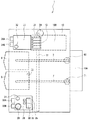
以下、本発明の第一の実施の形態について図面を参照して説明する。まず、図1乃至図3を参照して、第一の実施の形態のインクジェットプリンタ1(「印刷装置」に相当する)について説明する。図1は、第一の実施の形態のインクジェットプリンタ1の平面図であり、図2は、インクジェットプリンタ1の正面図であり、図3は、インクジェットプリンタ1の電気的構成を示すブロック図である。   Hereinafter, a first embodiment of the present invention will be described with reference to the drawings. First, an inkjet printer 1 (corresponding to a “printing apparatus”) according to a first embodiment will be described with reference to FIGS. 1 to 3. FIG. 1 is a plan view of the inkjet printer 1 according to the first embodiment, FIG. 2 is a front view of the inkjet printer 1, and FIG. 3 is a block diagram showing an electrical configuration of the inkjet printer 1. .

本実施の形態では、インクジェットプリンタ1は、インクを噴射するノズル面を具備するインクジェットヘッド21にインクを供給して、被記録媒体へ印刷を行う周知のインクジェットプリンタであり、被記録媒体としてTシャツ等の布帛を扱い、入力された画像情報等に基づいてTシャツ等の布帛への印刷を行うためのインクジェットプリンタである。図1及び図2に示すように、インクジェットプリンタ1は平面板状のベース2を下面に備え、また、装置全体を覆う本体カバー10が設けられ、本体カバー10の後端部には、後部カバー10Aが設けられている。   In the present embodiment, the inkjet printer 1 is a well-known inkjet printer that supplies ink to an inkjet head 21 having a nozzle surface for ejecting ink and performs printing on a recording medium. A T-shirt is used as the recording medium. Inkjet printers for handling fabrics such as T-shirts and printing on fabrics such as T-shirts based on input image information and the like. As shown in FIGS. 1 and 2, the inkjet printer 1 includes a flat plate-like base 2 on the lower surface, and a main body cover 10 that covers the entire apparatus is provided. A rear cover is provided at the rear end of the main body cover 10. 10A is provided.

なお、本実施の形態では、図1における左側をインクジェットプリンタ1の前側、図1における上側及び図2における左側をインクジェットプリンタ1の左端とし、図1における下側及び図2における右側をインクジェットプリンタ1の右側とする。そして、インクジェットプリンタ1の左右方向(図1における上下方向)がインクジェットヘッド21(キャリッジ13)が往復運動をする方向である主走査方向となる。   In the present embodiment, the left side in FIG. 1 is the front side of the inkjet printer 1, the upper side in FIG. 1 and the left side in FIG. 2 are the left end of the inkjet printer 1, and the lower side in FIG. On the right side. The horizontal direction of the inkjet printer 1 (the vertical direction in FIG. 1) is the main scanning direction, which is the direction in which the inkjet head 21 (carriage 13) reciprocates.

本体カバー10内の記録機構は、周知のインクジェット式記録機構であり、インクジェットプリンタ1の左右方向(図1における上下方向)にインクジェットヘッド21(「記録ヘッド」に相当する)を搭載したキャリッジ13の移動を案内するためのガイドレール11が架設されている。尚、キャリッジ13が「記録ヘッド搬送手段」に相当する。このガイドレール11の左端付近(図1における上端部付近)にキャリッジモータ24が設けられ、右端付近(図1における下端部付近)にプーリ(図示外)が設けられ、その間にキャリッジベルト(図示外)が架設されている。このキャリッジベルトはキャリッジ13の背面に固定されており、キャリッジモータ24の駆動によって、ガイドレール11に沿って、キャリッジ13が往復移動される。尚、ガイドレール11の右端又は左端の何れかにインクジェットヘッド21のメンテナンス行う図示外のメンテナンス部であるキャッピング機構、ワイプ機構及びパージ機構が設けられている。   The recording mechanism in the main body cover 10 is a well-known ink jet recording mechanism. The recording mechanism of the carriage 13 is mounted with an ink jet head 21 (corresponding to a “recording head”) in the left-right direction (vertical direction in FIG. A guide rail 11 is installed for guiding the movement. The carriage 13 corresponds to “recording head conveying means”. A carriage motor 24 is provided near the left end (near the upper end in FIG. 1) of this guide rail 11, and a pulley (not shown) is provided near the right end (near the lower end in FIG. 1). ) Is built. The carriage belt is fixed to the back surface of the carriage 13, and the carriage 13 is reciprocated along the guide rail 11 by driving the carriage motor 24. Note that a capping mechanism, a wiping mechanism, and a purging mechanism, which are maintenance parts (not shown) that perform maintenance of the inkjet head 21, are provided at either the right end or the left end of the guide rail 11.

次に、本実施の形態のインクジェットプリンタ1で、被記録媒体を保持する「媒体保持手段」としての第一プラテン5及び第二プラテン6の構造の詳細について説明する。インクジェットプリンタ1では、通常のインクジェットプリンタと異なり、同一形状の第一プラテン5及び第二プラテン6を一組備えており、インクジェットヘッド21の主走査方向と直交する副走査方向(インクジェットプリンタ1の前後方向、図1に於ける左右方向)に平行に移動可能となっている。   Next, details of the structure of the first platen 5 and the second platen 6 as “medium holding means” for holding the recording medium in the inkjet printer 1 of the present embodiment will be described. Unlike a normal ink jet printer, the ink jet printer 1 includes a set of the first platen 5 and the second platen 6 having the same shape, and a sub-scanning direction orthogonal to the main scanning direction of the ink jet head 21 (before and after the ink jet printer 1). Direction, the horizontal direction in FIG. 1).

従って、ベース2には、(図1に於ける左右方向)に被記録媒体を保持する第一プラテン5の移動を案内するための「媒体搬送手段」としての第一送り機構7と、同様に第二プラテン6の移動を案内するための「媒体搬送手段」としての第二送り機構8とが並列(平行)に設けられている。この第一送り機構7は、図2に示すようにガイドレール7A,7Bと、当該ガイドレール7A,7Bの後端部(図1における右側の端部)に設けられたステッピングモータからなる第一プラテン搬送モータ71等(図1参照)から構成されており、第一プラテン搬送モータ71の駆動により第一プラテン5が、第一送り機構7のガイドレール7A,7Bに沿って副走査方向に往復移動する。なお、第一プラテン搬送モータ71は、本体カバー10の奥側(図1に於ける右側)に備えられている。また、第二送り機構8も、第一送り機構7と同様に、図2に示すようにガイドレール8A,8Bと、当該ガイドレール8A,8Bの後端部(図1における右側の端部)に設けられたステッピングモータからなる第二プラテン搬送モータ81等(図1参照)から構成されており、第二プラテン搬送モータ81の駆動により第二プラテン6が、送り機構8のガイドレール8A,8Bに沿って副走査方向に往復移動する。なお、第二プラテン搬送モータ81は、本体カバー10の奥側(図1に於ける右側)に備えられている。   Accordingly, the base 2 is provided with the same as the first feeding mechanism 7 as “medium conveying means” for guiding the movement of the first platen 5 holding the recording medium (in the horizontal direction in FIG. 1). A second feeding mechanism 8 as a “medium conveying means” for guiding the movement of the second platen 6 is provided in parallel (parallel). As shown in FIG. 2, the first feed mechanism 7 includes guide rails 7A, 7B and a stepping motor provided at the rear ends (right ends in FIG. 1) of the guide rails 7A, 7B. The platen transport motor 71 and the like (see FIG. 1) are configured, and the first platen 5 reciprocates in the sub-scanning direction along the guide rails 7A and 7B of the first feed mechanism 7 by driving the first platen transport motor 71. Moving. The first platen transport motor 71 is provided on the back side (the right side in FIG. 1) of the main body cover 10. Similarly to the first feed mechanism 7, the second feed mechanism 8 also has guide rails 8A and 8B and rear end portions (right end portions in FIG. 1) of the guide rails 8A and 8B, as shown in FIG. The second platen transport motor 81 and the like (see FIG. 1) are provided, and the second platen 6 is driven by the second platen transport motor 81 to guide rails 8A and 8B of the feed mechanism 8. And reciprocate in the sub-scanning direction. The second platen transport motor 81 is provided on the back side (the right side in FIG. 1) of the main body cover 10.

また、第一プラテン5及び第二プラテン6は、平面視五角形に形成され、詳細には、長方形状の板体の操作者に対向する側の短辺の中央が突出した形状の五角形であり、その上面(「保持面」に相当する)に、例えばTシャツなどの布帛からなる被記録媒体を水平に載置するのに適した形状となっている。   Further, the first platen 5 and the second platen 6 are formed in a pentagonal shape in plan view. Specifically, the first platen 5 and the second platen 6 are pentagons in which the center of the short side on the side facing the operator of the rectangular plate body protrudes. On the upper surface (corresponding to a “holding surface”), the recording medium made of a cloth such as a T-shirt has a shape suitable for horizontal placement.

また、第一プラテン5及び第二プラテン6の下方には、当該第一プラテン5及び第二プラテン6の上面と略平行な底面を有したトレー4,4,4が備えられている。このトレー4,4,4は、利用者がTシャツ等を第一プラテン5及び第二プラテン6に載置する際に、Tシャツの袖などがベース2へ落ちないように袖などを受けるものである。   Further, below the first platen 5 and the second platen 6, trays 4, 4, 4 having bottom surfaces substantially parallel to the top surfaces of the first platen 5 and the second platen 6 are provided. The trays 4, 4, 4 receive sleeves so that the sleeves of the T-shirt do not fall onto the base 2 when the user places the T-shirt on the first platen 5 and the second platen 6. It is.

また、図2に示すように、本体カバー10の前面の右端部にはインクカートリッジ33A,33Bを収納したインクカートリッジ収納部33が設けられ、本体カバー10の前面の左端部にはインクカートリッジ34A,34Bを収納したインクカートリッジ収納部34が設けられている。このインクカートリッジ収納部33,34に収納されたCMYKのインクカートリッジには、インク供給チューブが設けられており、インクジェットヘッド21に接続し、当該インクジェットヘッド21へ各色のインクを供給している。   Further, as shown in FIG. 2, an ink cartridge storage portion 33 that stores ink cartridges 33 </ b> A and 33 </ b> B is provided at the right end portion of the front surface of the main body cover 10. An ink cartridge storage portion 34 that stores 34B is provided. The CMYK ink cartridges housed in the ink cartridge housings 33 and 34 are provided with ink supply tubes, which are connected to the ink jet head 21 and supply ink of each color to the ink jet head 21.

また、図1及び図2に示すように、インクジェットプリンタ1の前面の右端部の位置には、インクジェットプリンタ1の操作を行うための操作パネル28が設けられている。この操作パネル28には、印刷を指示する第一印刷開始ボタン29、各種の表示を行うLCDから構成されたディスプレイ30、印刷命令をキャンセルするキャンセルボタン31、データを受信したことを示すデータランプ35及びエラーを表示するエラーランプ36が設けられている。さらに、操作パネル28の下方には、前記インクカートリッジ収納部33が設けられている。また、図1及び図2に示すように、インクジェットプリンタ1の前面の左端部の位置には、インクジェットプリンタ1の操作を行うための操作パネル27が設けられている。この操作パネル27には、印刷を指示する第二印刷開始ボタン32が設けられている。さらに、操作パネル28の下方には、前記インクカートリッジ収納部34が設けられている。   As shown in FIGS. 1 and 2, an operation panel 28 for operating the inkjet printer 1 is provided at the position of the right end portion of the front surface of the inkjet printer 1. The operation panel 28 includes a first print start button 29 for instructing printing, a display 30 including an LCD for performing various displays, a cancel button 31 for canceling a print command, and a data lamp 35 indicating that data has been received. An error lamp 36 for displaying an error is provided. Further, the ink cartridge storage portion 33 is provided below the operation panel 28. As shown in FIGS. 1 and 2, an operation panel 27 for operating the inkjet printer 1 is provided at the position of the left end portion of the front surface of the inkjet printer 1. The operation panel 27 is provided with a second print start button 32 for instructing printing. Further, the ink cartridge storage portion 34 is provided below the operation panel 28.

次に、図3を参照して、インクジェットプリンタ1の電気的な構成について説明する。図3に示すように、インクジェットプリンタ1の印刷制御部100には、インクジェットプリンタ1全体の制御を司るCPU110が設けられ、CPU110には、バス115を介して、CPU110が実行する各種の制御プログラム等を記憶したROM120と、データを一時的に記憶するRAM130とが接続されている。また、CPU110には、インクジェットヘッド21の各チャンネルに設けられた圧電アクチュエータを駆動制御させるための「記録ヘッド制御手段」としてのインクジェットヘッド制御部140、キャリッジモータ24を駆動制御させるためのキャリッジモータ駆動部145、第一プラテン搬送モータ71及び第二プラテン搬送モータ81を駆動制御させるためのプラテン搬送モータ駆動部147、第一印刷開始ボタン29と第二印刷開始ボタン32とキャンセルボタン31と後述する拡張プラテンセンサ52からの入力を受け付けるセンサ入力部148、データランプ35とエラーランプ36とディスプレイ30とを制御する表示制御部149、及び外部のパーソナルコンピュータ(PC)90と、ユニバーサル・パラレル・バスで接続する通信処理部125とを備えている。   Next, the electrical configuration of the inkjet printer 1 will be described with reference to FIG. As shown in FIG. 3, the print control unit 100 of the inkjet printer 1 is provided with a CPU 110 that controls the entire inkjet printer 1, and various control programs executed by the CPU 110 via a bus 115 are provided in the CPU 110. Are connected to a RAM 120 for temporarily storing data. In addition, the CPU 110 has an inkjet head control unit 140 serving as a “recording head control unit” for driving and controlling the piezoelectric actuator provided in each channel of the inkjet head 21, and a carriage motor drive for driving and controlling the carriage motor 24. Unit 145, platen transport motor drive unit 147 for driving and controlling the first platen transport motor 71 and the second platen transport motor 81, the first print start button 29, the second print start button 32, the cancel button 31, and an extension described later. Connected to the sensor input unit 148 that receives input from the platen sensor 52, the display control unit 149 that controls the data lamp 35, the error lamp 36, and the display 30, and an external personal computer (PC) 90 through a universal parallel bus. And a communication processing unit 125 that.

次に、図4及び図5を参照して、インクジェットプリンタ1の第一プラテン5の第一送り機構7について説明する。図4は、第一プラテン5の送り機構を模式化した平面図であり、図5は、第一プラテン5の送り機構を模式化した左側面図である。尚、図4及び図5における左側がインクジェットプリンタ1の前側であり、右側がインクジェットプリンタ1の奥側である。   Next, the first feed mechanism 7 of the first platen 5 of the inkjet printer 1 will be described with reference to FIGS. 4 and 5. FIG. 4 is a plan view schematically showing the feeding mechanism of the first platen 5, and FIG. 5 is a left side view schematically showing the feeding mechanism of the first platen 5. 4 and 5, the left side is the front side of the ink jet printer 1, and the right side is the back side of the ink jet printer 1.

図4及び図5に示すように、第一送り機構7では、第一プラテン搬送モータ71の回転に伴い回転するモータプーリ73と大プーリ72とにモータベルト79が架設されており、第一プラテン搬送モータ71の回転に伴い、モータプーリ73が回転し、大プーリ72が回転する。そして、大プーリ72の回転軸と同じ軸を回転軸とする第一ベルトプーリ74が設けられており、大プーリ72の回転と同期して第一ベルトプーリ74も回転する。これらの第一プラテン搬送モータ71、モータプーリ73、大プーリ72、第一ベルトプーリ74は、インクジェットプリンタ1の本体カバー10の内部の第一プラテン5の移動面よりも下方に設けられている。そして、第一ベルトプーリ74に対応して、インクジェットプリンタ1の手前側(図1、図4及び図5に於ける左側)に第二ベルトプーリ75が設けられ、第一ベルトプーリ74と第二ベルトプーリ75との間にタイミングベルト78が架設されている。この第二ベルトプーリ75の直径は第一ベルトプーリ74と同じサイズである。   As shown in FIGS. 4 and 5, in the first feed mechanism 7, a motor belt 79 is installed on a motor pulley 73 and a large pulley 72 that rotate with the rotation of the first platen transport motor 71. As the motor 71 rotates, the motor pulley 73 rotates and the large pulley 72 rotates. A first belt pulley 74 having a rotation axis that is the same as the rotation axis of the large pulley 72 is provided, and the first belt pulley 74 also rotates in synchronization with the rotation of the large pulley 72. The first platen transport motor 71, the motor pulley 73, the large pulley 72, and the first belt pulley 74 are provided below the moving surface of the first platen 5 inside the main body cover 10 of the inkjet printer 1. Corresponding to the first belt pulley 74, a second belt pulley 75 is provided on the front side of the inkjet printer 1 (the left side in FIGS. 1, 4 and 5). A timing belt 78 is installed between the belt pulley 75 and the belt pulley 75. The diameter of the second belt pulley 75 is the same size as the first belt pulley 74.

また、タイミングベルト78は、インクジェットプリンタ1のインクジェットヘッド21の主走査方向(ガイドレール11の延設方向)と垂直に架設されるように、第一ベルトプーリ74の中心と第二ベルトプーリ75の中心とを結ぶ直線がインクジェットヘッド21の主走査方向(ガイドレール11の延設方向)と垂直となるように配置されている。さらに、タイミングベルト78には第一プラテン5がプラテン取付部51により固定されており、タイミングベルト78の回転に伴い、第一プラテン5がインクジェットプリンタ1の前後方向(図4及び図5に示す矢印A方向)に移動する。このようにして、第一プラテン搬送モータ71の回転運動を、モータプーリ73、モータベルト79、大プーリ72、第一ベルトプーリ74、タイミングベルト78、第二ベルトプーリ75を介して第一プラテン5の水平運動に換えている。   In addition, the timing belt 78 is installed perpendicularly to the main scanning direction of the ink jet head 21 of the ink jet printer 1 (the extending direction of the guide rail 11) and between the center of the first belt pulley 74 and the second belt pulley 75. The straight line connecting the centers is arranged so as to be perpendicular to the main scanning direction of the inkjet head 21 (the extending direction of the guide rail 11). Further, the first platen 5 is fixed to the timing belt 78 by the platen mounting portion 51, and the first platen 5 is moved in the front-rear direction of the inkjet printer 1 (arrows shown in FIGS. 4 and 5) as the timing belt 78 rotates. A direction). In this way, the rotational movement of the first platen transport motor 71 is transmitted to the first platen 5 via the motor pulley 73, the motor belt 79, the large pulley 72, the first belt pulley 74, the timing belt 78, and the second belt pulley 75. Changed to horizontal movement.

ここで、第一プラテン搬送モータ71について説明する。第一プラテン搬送モータ71は、周知の1−2相励磁方式ステッピングモータであり、ローターの周囲に電磁石となる固定子が設けられており、固定子を励磁することにより電磁石(固定子)にローターが引き付けられて、1ステップずつローターが回転する。具体的には、固定子にはA相、逆A相、B相、逆B相の4つの励磁相があり、時計回りにA相、B相、逆A相、逆B相、A相、B相、…の順に並んでいる。そして、A相のみ、A相とB相、B相のみ、B相と逆A相、逆A相のみ、逆A相と逆B相、逆B相のみ、逆B相とA相、A相のみ、…という順で励磁し、励磁されている励磁相がN極を帯びることにより、ローターのS極が引き付けられ、N極が遠ざけられることにより、1ステップずつローターが回転する。   Here, the first platen transport motor 71 will be described. The first platen transport motor 71 is a well-known 1-2 phase excitation stepping motor. A stator that serves as an electromagnet is provided around the rotor, and the rotor is moved to the electromagnet (stator) by exciting the stator. Is attracted and the rotor rotates step by step. Specifically, the stator has four excitation phases of A phase, reverse A phase, B phase, and reverse B phase. A phase, B phase, reverse A phase, reverse B phase, A phase, They are arranged in the order of B phase. And only A phase, A phase and B phase, B phase only, B phase and reverse A phase, only reverse A phase, reverse A phase and reverse B phase, only reverse B phase, reverse B phase and A phase, A phase Only when the excitation phase is excited and the excited excitation phase has an N pole, the S pole of the rotor is attracted and the N pole is moved away, thereby rotating the rotor step by step.

つまり、励磁を連続的に行うことにより、第一プラテン搬送モータ71を回転させることができ、第一プラテン5をインクジェットプリンタ1の前後方向に水平移動させることができる。また、ローターのN極とS極との数により、1回の励磁でローターが回転する角度が決まっており、第一プラテン搬送モータ71の回転ステップ数により第一プラテン5の移動距離を制御することができる。尚、第二プラテン6を搬送する第二送り機構8も上記第一送り機構7と同様の構成になっている。   That is, by continuously performing excitation, the first platen transport motor 71 can be rotated, and the first platen 5 can be moved horizontally in the front-rear direction of the inkjet printer 1. Further, the angle at which the rotor rotates by one excitation is determined by the number of N poles and S poles of the rotor, and the moving distance of the first platen 5 is controlled by the number of rotation steps of the first platen transport motor 71. be able to. The second feed mechanism 8 that transports the second platen 6 has the same configuration as the first feed mechanism 7.

次に、図6乃至図9を参照して、第一プラテン5及び第二プラテン6を連結する「連結手段」であり、第一プラテン5及び第二プラテン6に被せる拡張プラテン40について説明する。図6は、拡張プラテン40の斜視図であり、図7は、拡張プラテン40を第一プラテン5及び第二プラテン6に被せた状態のインクジェットプリンタ1の平面図であり、図8は、第一プラテン5及び第二プラテン6に拡張プラテン40を被せた状態の第一プラテン5の側面図であり、図9は、第一プラテン5及び第二プラテン6から拡張プラテン40を外した状態の第一プラテン5の側面図である。   Next, the expansion platen 40 that covers the first platen 5 and the second platen 6 as a “connection means” for connecting the first platen 5 and the second platen 6 will be described with reference to FIGS. 6 is a perspective view of the expansion platen 40, FIG. 7 is a plan view of the inkjet printer 1 in a state where the expansion platen 40 is put on the first platen 5 and the second platen 6, and FIG. FIG. 9 is a side view of the first platen 5 in a state where the expansion platen 40 is put on the platen 5 and the second platen 6, and FIG. 9 shows the first platen 5 in a state where the expansion platen 40 is removed from the first platen 5 and the second platen 6. 3 is a side view of the platen 5. FIG.

図6に示すように、拡張プラテン40は、内部に第一プラテン5及び第二プラテン6が入る大きさの長方形の蓋状に形成され、図7に示すように、第一プラテン5及び第二プラテン6に上方から被せるようになっている。また、この拡張プラテン40には、図6に示すように、遮光性を有する部材から構成された突起部41が下方に突出されている。この突起部41は、後述する拡張プラテンセンサ52に挿入されて、拡張プラテンセンサ52を構成するフォトカプラの発光部と受光部間の光を遮断して、拡張プラテンセンサ52により、拡張プラテン40の着脱が検出される。   As shown in FIG. 6, the expansion platen 40 is formed in a rectangular lid shape having a size in which the first platen 5 and the second platen 6 can be inserted. As shown in FIG. 7, the first platen 5 and the second platen 40 are formed. The platen 6 is covered from above. Further, as shown in FIG. 6, the extended platen 40 has a protruding portion 41 made of a light-shielding member protruding downward. The protrusion 41 is inserted into an extended platen sensor 52 described later, blocks light between the light emitting part and the light receiving part of the photocoupler constituting the extended platen sensor 52, and the extended platen sensor 52 causes the extended platen 40 to Detachment is detected.

次に、「拡張テーブル検出手段」としての拡張プラテンセンサ52の構造を図7乃至図9を参照して説明する。図7に示すように、拡張プラテンセンサ52は、第一プラテン5の後端部に設けられたフォトカプラからなるセンサであり、図示外の発光部と受光部とを備えている。図7及び図8に示すように、拡張プラテン40を第一プラテン5及び第二プラテン6上に被せた場合には、機械的に第一プラテン5及び第二プラテン6が一体化されて結合されるだけでなく、拡張プラテンセンサ52の発光部と受光部との間に、拡張プラテン40に設けられた突起部41が挿入されて、発光部と受光部との間の光を遮光するようになっている。この状態で、拡張プラテンセンサ52はON状態になる。また、図9に示すように、拡張プラテン40を取り外すと、拡張プラテンセンサ52の発光部と受光部との間の突起部41が無くなり、拡張プラテンセンサ52の発光部からの光は、受光部で受光されて拡張プラテンセンサ52はOFF状態になる。   Next, the structure of the extension platen sensor 52 as “extension table detection means” will be described with reference to FIGS. As shown in FIG. 7, the extended platen sensor 52 is a sensor made of a photocoupler provided at the rear end of the first platen 5, and includes a light emitting unit and a light receiving unit (not shown). As shown in FIGS. 7 and 8, when the expansion platen 40 is placed on the first platen 5 and the second platen 6, the first platen 5 and the second platen 6 are mechanically integrated and coupled. In addition, a projection 41 provided on the extended platen 40 is inserted between the light emitting part and the light receiving part of the extended platen sensor 52 so as to block the light between the light emitting part and the light receiving part. It has become. In this state, the extended platen sensor 52 is turned on. Further, as shown in FIG. 9, when the expansion platen 40 is removed, the protrusion 41 between the light emitting portion and the light receiving portion of the expansion platen sensor 52 disappears, and the light from the light emitting portion of the expansion platen sensor 52 is received by the light receiving portion. And the extended platen sensor 52 is turned off.

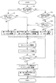
次に、図10に示すフローチャートを参照して、本インクジェットプリンタ1における印刷範囲確認処理について説明する。図10は、印刷制御部100のCPU110が実行する印刷範囲確認処理のフローチャートである。まず、外部のパーソナルコンピュータ90からユニバーサル・シリアル・バスを介して通信処理部125に印刷データが受信されると(S1:YES)、次に、拡張プラテンセンサ52は、ON状態か否か、即ち、拡張プラテン40が装着されているかを判断する(S2)。尚、受信された印刷データは、図3に示すRAM130に記憶される。   Next, a print range confirmation process in the inkjet printer 1 will be described with reference to a flowchart shown in FIG. FIG. 10 is a flowchart of print range confirmation processing executed by the CPU 110 of the print control unit 100. First, when print data is received from the external personal computer 90 via the universal serial bus to the communication processing unit 125 (S1: YES), next, whether or not the extended platen sensor 52 is in an ON state, that is, Then, it is determined whether the expansion platen 40 is attached (S2). The received print data is stored in the RAM 130 shown in FIG.

S2の判断処理で、拡張プラテンセンサ52は、ON状態、即ち、拡張プラテン40が装着されていると判断されると(S2:YES)、印刷範囲を一例として、16インチ×32インチに設定する(S3)。この設定は、図3に示すRAM130に記憶される。また、拡張プラテンセンサ52は、OFF状態、即ち、拡張プラテン40が装着されていないと判断されると(S2:NO)、印刷範囲を一例として、14インチ×16インチに設定する(S4)。この設定は、図3に示すRAM130に記憶される。即ち、拡張プラテン40が装着されていると判定された場合には、第一プラテン5又は第二プラテン6を単独で使用する場合の印刷範囲14インチ×16インチよりも広い、16インチ×32インチの印刷範囲に設定し、拡張プラテン40が装着されていないと判定された場合には、第一プラテン5又は第二プラテン6を単独で使用する場合の印刷範囲14インチ×16インチに設定されるのである。尚、S3及びS4の処理を実行する印刷制御部100のCPU110が「印刷可能範囲変更手段」に相当する。また、印刷範囲は、一例であり、第一プラテン5及び第二プラテン6の大きさと、拡張プラテン40の大きさとに応じて予め定めておけば良い。   If it is determined in S2 that the extended platen sensor 52 is in the ON state, that is, if the extended platen 40 is mounted (S2: YES), the print range is set to 16 inches × 32 inches as an example. (S3). This setting is stored in the RAM 130 shown in FIG. Further, when the extended platen sensor 52 is in the OFF state, that is, when it is determined that the extended platen 40 is not attached (S2: NO), the print range is set to 14 inches × 16 inches as an example (S4). This setting is stored in the RAM 130 shown in FIG. That is, if it is determined that the expansion platen 40 is mounted, the printing range is 14 inches × 32 inches, which is wider than the printing range of 14 inches × 16 inches when the first platen 5 or the second platen 6 is used alone. In the case where it is determined that the extended platen 40 is not attached, the print range when the first platen 5 or the second platen 6 is used alone is set to 14 inches × 16 inches. It is. The CPU 110 of the print control unit 100 that executes the processes of S3 and S4 corresponds to the “printable range changing unit”. The printing range is an example, and may be determined in advance according to the size of the first platen 5 and the second platen 6 and the size of the expansion platen 40.

次に、S3又はS4の処理で、設定された印刷範囲にRAM130に記憶された印刷データによる印刷が入るか否かを判定する(S5)。この判断は、S3又はS4の処理で、設定された印刷範囲と、RAM130に記憶された印刷データに含まれている印刷の大きさを示すデータと比較して行う。印刷範囲に入らない場合には(S5:NO)、警告をディスプレイ30に表示する(S6)。印刷範囲に入る場合には(S5:YES)、処理を終了する。尚、S1で、印刷データの受信がない場合には(S1:NO)、処理を終了する。この印刷範囲確認処理は、例えば、数ミリ秒単位の割り込み動作により、繰り返し実行されて、印刷データの受信を監視している。   Next, in step S3 or S4, it is determined whether or not printing by the print data stored in the RAM 130 enters the set print range (S5). This determination is made by comparing the set print range with the data indicating the print size included in the print data stored in the RAM 130 in the process of S3 or S4. If the print range is not entered (S5: NO), a warning is displayed on the display 30 (S6). If the print range is entered (S5: YES), the process is terminated. If no print data is received in S1 (S1: NO), the process is terminated. This print range confirmation process is repeatedly executed, for example, by an interrupt operation in units of several milliseconds to monitor reception of print data.

次に、図11に示すフローチャートを参照して、本インクジェットプリンタ1における印刷処理について説明する。図11は、印刷制御部100のCPU110が実行する印刷処理のフローチャートである。インクジェットプリンタ1の第一印刷開始ボタン29が押下されると(S11:YES)、拡張プラテンセンサ52は、ON状態か否か、即ち、拡張プラテン40が装着されているかを判断する(S12)。S12の判断処理で、拡張プラテンセンサ52は、ON状態、即ち、拡張プラテン40が装着されていると判断されると(S12:YES)、第一プラテン搬送モータ71及び第二プラテン搬送モータ81を同期駆動する(S13)。即ち、第一プラテン搬送モータ71及び第二プラテン搬送モータ81を同時に同じステップだけ同方向に駆動する(S13)。このS13のステップの処理を実行するCPU110が「同期制御手段」に相当する。尚、同期手段としては、広義には、この「同期制御手段」であるこのS13のステップの処理を実行するCPU110と、拡張プラテン40及び後述する拡張プラテン42,43が該当する。また、S12の判断処理で、拡張プラテンセンサ52は、OFF状態、即ち、拡張プラテン40が装着されていないと判断されると(S12:NO)、第一プラテン搬送モータ71のみ駆動する(S14)。   Next, a printing process in the inkjet printer 1 will be described with reference to a flowchart shown in FIG. FIG. 11 is a flowchart of print processing executed by the CPU 110 of the print control unit 100. When the first print start button 29 of the inkjet printer 1 is pressed (S11: YES), the extended platen sensor 52 determines whether or not the extended platen 40 is attached (S12). If it is determined in S12 that the expansion platen sensor 52 is in the ON state, that is, if the expansion platen 40 is mounted (S12: YES), the first platen transport motor 71 and the second platen transport motor 81 are turned on. Drive synchronously (S13). That is, the first platen transport motor 71 and the second platen transport motor 81 are simultaneously driven in the same direction by the same step (S13). The CPU 110 that executes the process of step S13 corresponds to “synchronization control means”. Note that the synchronization means broadly corresponds to the CPU 110 that executes the processing of step S13 as the “synchronization control means”, the extended platen 40, and extended platens 42 and 43 described later. In the determination process of S12, when it is determined that the expansion platen sensor 52 is in the OFF state, that is, the expansion platen 40 is not mounted (S12: NO), only the first platen transport motor 71 is driven (S14). .

また、インクジェットプリンタ1の第一印刷開始ボタン29が押下されず(S11:NO)、第二印刷開始ボタン32が押下されると(S15:YES)、拡張プラテンセンサ52は、ON状態か否か、即ち、拡張プラテン40が装着されているかを判断する(S16)。S16の判断処理で、拡張プラテンセンサ52は、ON状態、即ち、拡張プラテン40が装着されていると判断されると(S16:YES)、第一プラテン搬送モータ71及び第二プラテン搬送モータ81を同期駆動する(S13)。即ち、第一プラテン搬送モータ71及び第二プラテン搬送モータ81を同時に同じステップだけ同方向に駆動する(S13)。また、S16の判断処理で、拡張プラテンセンサ52は、OFF状態、即ち、拡張プラテン40が装着されていないと判断されると(S16:NO)、第二プラテン搬送モータ81のみ駆動する(S17)。   If the first print start button 29 of the inkjet printer 1 is not pressed (S11: NO) and the second print start button 32 is pressed (S15: YES), whether or not the extended platen sensor 52 is in the ON state. That is, it is determined whether or not the expansion platen 40 is attached (S16). In the determination process of S16, when it is determined that the expansion platen sensor 52 is in the ON state, that is, the expansion platen 40 is mounted (S16: YES), the first platen conveyance motor 71 and the second platen conveyance motor 81 are turned on. Drive synchronously (S13). That is, the first platen transport motor 71 and the second platen transport motor 81 are simultaneously driven in the same direction by the same step (S13). In the determination process of S16, when it is determined that the expansion platen sensor 52 is in the OFF state, that is, the expansion platen 40 is not mounted (S16: NO), only the second platen transport motor 81 is driven (S17). .

次いで、キャリッジモータ24を駆動し(S18)、インクジェットヘッド21を駆動し(S19)、印刷データが最後になるまで(S20:NO)、インクジェットヘッド21を用いて印刷を行う。印刷データが最後になると(S20:YES)、インクジェットヘッド21の駆動を終了して、インクジェットヘッド21をメンテナンス部に移動する(S21)。次いで、第一プラテン5及び第二プラテン6を着脱位置、即ち、第一プラテン5及び第二プラテン6が本体カバー10から飛び出した位置に移動する(S22)。その後、使用者が、拡張プラテン40又は、第一プラテン5、第二プラテン6に載置された布帛を外す。   Next, the carriage motor 24 is driven (S18), the ink-jet head 21 is driven (S19), and printing is performed using the ink-jet head 21 until the last print data (S20: NO). When the print data comes to the end (S20: YES), the driving of the inkjet head 21 is terminated, and the inkjet head 21 is moved to the maintenance unit (S21). Next, the first platen 5 and the second platen 6 are moved to the attachment / detachment positions, that is, the positions at which the first platen 5 and the second platen 6 protrude from the main body cover 10 (S22). Thereafter, the user removes the cloth placed on the expansion platen 40 or the first platen 5 and the second platen 6.

次に、図2、図12、図13を参照して、同一データを布帛二枚に印刷する場合を説明する。図12は、第一プラテン5、第二プラテン6に各々布帛の一例であるTシャツ60を載置した状態のインクジェットプリンタ1の正面図であり、図13は、印刷データを編集するパーソナルコンピュータ90の画面上に表示された印刷データの一例である。同一データをTシャツ60二枚に印刷する場合は、図13に示すように、Tシャツ60の胸に印刷する印刷データ(一例として14インチ×16インチの印刷サイズ)のものを、パーソナルコンピュータ90で作成して、インクジェットプリンタ1へ送信する。この場合には、印刷データは、1枚分のみ送られる。インクジェットプリンタ1側で、拡張プラテン40を搭載せずに、第一印刷開始ボタン29が押下されると、第一プラテン5に載置されているTシャツ60に前記印刷データの図柄で印刷する。その後、拡張プラテン40を搭載せずに、第二印刷開始ボタン32が押下されると、第二プラテン6に載置されているTシャツ60に、同じ印刷データの図柄で印刷する。従って、使用者が作成するのは、1枚のTシャツ60に対する印刷データのみである。従って、横長のキャンパスに2つの同一データをレイアウトする必要はない。尚、インクジェットプリンタ1の操作パネル28に同時印刷ボタンを設け、この同時印刷ボタンが押下されたときに、拡張プラテン40が装着されていないことが、拡張プラテンセンサ52により検出された場合には、第一プラテン5及び第二プラテン6を同期駆動し、第一プラテン5及び第二プラテン6に各々載置されているTシャツ60に、同時に同じ図柄を印刷するようにしても良い。   Next, a case where the same data is printed on two sheets of fabric will be described with reference to FIGS. FIG. 12 is a front view of the inkjet printer 1 in a state where a T-shirt 60 as an example of a fabric is placed on each of the first platen 5 and the second platen 6, and FIG. 13 is a personal computer 90 for editing print data. 6 is an example of print data displayed on the screen. When printing the same data on two T-shirts 60, as shown in FIG. 13, the print data to be printed on the chest of the T-shirt 60 (for example, a print size of 14 inches × 16 inches) is personal computer 90. And is transmitted to the ink jet printer 1. In this case, only one print data is sent. When the first printing start button 29 is pressed without mounting the expansion platen 40 on the ink jet printer 1 side, printing is performed on the T-shirt 60 placed on the first platen 5 with the design of the print data. After that, when the second print start button 32 is pressed without mounting the extended platen 40, printing is performed on the T-shirt 60 placed on the second platen 6 with the same print data pattern. Therefore, the user creates only print data for one T-shirt 60. Therefore, it is not necessary to lay out two identical data on a horizontally long campus. In the case where a simultaneous printing button is provided on the operation panel 28 of the inkjet printer 1 and the expansion platen sensor 52 detects that the expansion platen 40 is not mounted when the simultaneous printing button is pressed, The first platen 5 and the second platen 6 may be driven synchronously, and the same design may be simultaneously printed on the T-shirts 60 placed on the first platen 5 and the second platen 6, respectively.

次に、図14乃至図16を参照して、大きな図柄のデータを1つの布帛に同時に印刷する場合を説明する。図14は、第一プラテン5、第二プラテン6上に拡張プラテン40を載置した状態のインクジェットプリンタ1の正面図であり、図15は、拡張プラテン40上に布帛の一例であるTシャツ60を載置した状態のインクジェットプリンタ1の正面図であり、図16は、印刷データを編集するパーソナルコンピュータ90の画面上に表示された大きな図柄の印刷データの一例である。大きな図柄の印刷データをTシャツ60に印刷する場合は、図16に示すように、Tシャツ60の胸に印刷する印刷データ(一例として16インチ×32インチの印刷サイズ)のものを、パーソナルコンピュータ90で作成して、インクジェットプリンタ1へ送信する。インクジェットプリンタ1では、図14に示すように、第一プラテン5、第二プラテン6上に拡張プラテン40が載置され、図15に示すように、拡張プラテン40上に大きなTシャツ60が、横向きに載置される。従って、広い印刷範囲に大きな画像をレイアウトすることができる。   Next, with reference to FIG. 14 to FIG. 16, a case where large symbol data is simultaneously printed on one fabric will be described. FIG. 14 is a front view of the inkjet printer 1 in a state where the extended platen 40 is placed on the first platen 5 and the second platen 6, and FIG. 15 is a T-shirt 60 that is an example of a fabric on the extended platen 40. Is a front view of the ink jet printer 1 in a state where is mounted, and FIG. 16 is an example of print data of a large design displayed on the screen of the personal computer 90 for editing the print data. When printing large-sized print data on the T-shirt 60, as shown in FIG. 16, the print data to be printed on the chest of the T-shirt 60 (for example, a print size of 16 inches × 32 inches) is used as a personal computer. The data is created at 90 and transmitted to the inkjet printer 1. In the inkjet printer 1, as shown in FIG. 14, the extended platen 40 is placed on the first platen 5 and the second platen 6, and as shown in FIG. 15, the large T-shirt 60 is placed sideways on the extended platen 40. Placed on. Therefore, a large image can be laid out over a wide print range.

次に、図17に示すフローチャートを参照して、本インクジェットプリンタ1における印刷処理の変形例について説明する。図17は、印刷処理の変形例のフローチャートである。この印刷処理の変形例では、第一プラテン搬送モータ71は、Tシャツ60が搭載された拡張プラテン40が被せられた第一プラテン5及び第二プラテン6を駆動できる十分な出力を有する大型のステップモータとし、第二プラテン搬送モータ81は、Tシャツ60が搭載された第二プラテン6のみを駆動できる出力の通常のステップモータとする。そして、拡張プラテン40を使用する場合に、第二プラテン搬送モータ81の励磁を解除し、第一プラテン搬送モータ71のみで、駆動するものである。   Next, a modification of the printing process in the inkjet printer 1 will be described with reference to the flowchart shown in FIG. FIG. 17 is a flowchart of a modification of the printing process. In this modification of the printing process, the first platen transport motor 71 is a large step having a sufficient output capable of driving the first platen 5 and the second platen 6 covered with the expansion platen 40 on which the T-shirt 60 is mounted. The second platen transport motor 81 is a normal step motor with an output capable of driving only the second platen 6 on which the T-shirt 60 is mounted. When the extended platen 40 is used, the excitation of the second platen transport motor 81 is released and the first platen transport motor 71 is used to drive.

この変形例では、初めに、インクジェットプリンタ1の第一印刷開始ボタン29が押下されると(S21:YES)、拡張プラテンセンサ52は、ON状態か否か、即ち、拡張プラテン40が装着されているかを判断する(S22)。S22の判断処理で、拡張プラテンセンサ52は、ON状態、即ち、拡張プラテン40が装着されていると判断されると(S22:YES)、第二プラテン搬送モータ81の励磁を解除し、第一プラテン搬送モータ71を駆動する(S23)。また、S22の判断処理で、拡張プラテンセンサ52は、OFF状態、即ち、拡張プラテン40が装着されていないと判断されると(S22:NO)、第一プラテン搬送モータ71のみ駆動する(S24)。   In this modification, first, when the first print start button 29 of the inkjet printer 1 is pressed (S21: YES), whether or not the expansion platen sensor 52 is in an ON state, that is, the expansion platen 40 is mounted. (S22). In the determination process of S22, when it is determined that the expansion platen sensor 52 is in the ON state, that is, the expansion platen 40 is mounted (S22: YES), the excitation of the second platen transport motor 81 is released, and the first The platen transport motor 71 is driven (S23). In the determination process of S22, when it is determined that the expansion platen sensor 52 is in the OFF state, that is, the expansion platen 40 is not attached (S22: NO), only the first platen transport motor 71 is driven (S24). .

また、インクジェットプリンタ1の第一印刷開始ボタン29が押下されず(S21:NO)、第二印刷開始ボタン32が押下されると(S25:YES)、拡張プラテンセンサ52は、ON状態か否か、即ち、拡張プラテン40が装着されているかを判断する(S26)。S26の判断処理で、拡張プラテンセンサ52は、ON状態、即ち、拡張プラテン40が装着されていると判断されると(S26:YES)、第二プラテン搬送モータ81の励磁を解除し、第一プラテン搬送モータ71を駆動する(S23)。また、S26の判断処理で、拡張プラテンセンサ52は、OFF状態、即ち、拡張プラテン40が装着されていないと判断されると(S26:NO)、第二プラテン搬送モータ81のみ駆動する(S27)。   If the first print start button 29 of the inkjet printer 1 is not pressed (S21: NO) and the second print start button 32 is pressed (S25: YES), whether or not the extended platen sensor 52 is in the ON state. That is, it is determined whether the expansion platen 40 is attached (S26). In the determination process of S26, when it is determined that the expansion platen sensor 52 is in the ON state, that is, the expansion platen 40 is mounted (S26: YES), the excitation of the second platen transport motor 81 is released, and the first The platen transport motor 71 is driven (S23). If it is determined in S26 that the expansion platen sensor 52 is in the OFF state, that is, the expansion platen 40 is not attached (S26: NO), only the second platen transport motor 81 is driven (S27). .

次いで、キャリッジモータ24を駆動し(S28)、インクジェットヘッド21を駆動し(S29)、印刷データが最後になるまで(S30:NO)、インクジェットヘッド21を用いて印刷を行う。印刷データが最後になると(S30:YES)、インクジェットヘッド21の駆動を終了して、インクジェットヘッド21をメンテナンス部に移動する(S31)。次いで、第一プラテン5及び第二プラテン6を着脱位置、即ち、第一プラテン5及び第二プラテン6が本体カバー10から飛び出した位置に移動する(S32)。その後、使用者が、拡張プラテン40又は、第一プラテン5、第二プラテン6に載置された布帛を外す。   Next, the carriage motor 24 is driven (S28), the inkjet head 21 is driven (S29), and printing is performed using the inkjet head 21 until the print data is the last (S30: NO). When the print data comes to the end (S30: YES), the driving of the inkjet head 21 is terminated, and the inkjet head 21 is moved to the maintenance unit (S31). Next, the first platen 5 and the second platen 6 are moved to the attachment / detachment positions, that is, the positions at which the first platen 5 and the second platen 6 protrude from the main body cover 10 (S32). Thereafter, the user removes the cloth placed on the expansion platen 40 or the first platen 5 and the second platen 6.

以上説明したように第一の実施の形態のインクジェットプリンタ1では、第一プラテン5及び第二プラテン6を備え、拡張プラテン40を第一プラテン5及び第二プラテン6上に装着することにより、印刷範囲を第一プラテン5又は第二プラテン6を使用するものに比べて拡大することができる。また、拡張プラテン40の装着を検出する拡張プラテンセンサ52を備えているので、当該拡張プラテンセンサ52の検出結果により、拡張プラテン40の装着が検出された場合には、第一プラテン搬送モータ71及び第二プラテン搬送モータ81の同期駆動(変形例の場合には、第二プラテン搬送モータ81の励磁解除及び第一プラテン搬送モータ71の駆動)を行うことができる。また、拡張プラテンセンサ52の検出結果により、拡張プラテン40の装着が検出されない場合には、第一プラテン搬送モータ71又は第二プラテン搬送モータ81の単独駆動を行うことができる。従って、使用者は、拡張プラテン40を装着するだけで、当該拡張プラテン40の大きさに応じて、印刷範囲を拡大できる。さらに、同一データで複数枚の被覆に印刷する場合には、拡張プラテン40を使用せず、印刷データを1つインクジェットプリンタ1に送信するだけで、複数のプラテンを使用して、複数枚の布帛の印刷が出来る。従って、印刷データ及び被印刷媒体の大きさに応じて、最適な媒体保持手段を使用することができ、最適な印刷時間と生産性を得ることができる。   As described above, the inkjet printer 1 according to the first embodiment includes the first platen 5 and the second platen 6, and the expansion platen 40 is mounted on the first platen 5 and the second platen 6 to perform printing. The range can be expanded compared to those using the first platen 5 or the second platen 6. Further, since the expansion platen sensor 52 that detects the attachment of the expansion platen 40 is provided, when the attachment of the expansion platen 40 is detected by the detection result of the expansion platen sensor 52, the first platen transport motor 71 and The second platen transport motor 81 can be synchronously driven (in the case of a modification, the excitation of the second platen transport motor 81 is released and the first platen transport motor 71 is driven). Further, when the attachment of the expansion platen 40 is not detected based on the detection result of the expansion platen sensor 52, the first platen conveyance motor 71 or the second platen conveyance motor 81 can be driven alone. Therefore, the user can expand the printing range according to the size of the expansion platen 40 only by mounting the expansion platen 40. Furthermore, when printing on a plurality of coatings with the same data, a plurality of fabrics can be used by using a plurality of platens by transmitting only one print data to the inkjet printer 1 without using the expansion platen 40. Can be printed. Therefore, the optimum medium holding means can be used according to the print data and the size of the printing medium, and the optimum printing time and productivity can be obtained.

尚、本発明は、上記第一の実施の形態のインクジェットプリンタ1に限られず各種の変形が可能である。例えば、拡張プラテンセンサ52は、第二プラテン6に設けても良い。また、図18に示す第二の実施の形態のインクジェットプリンタ101のように、第一プラテン5及び第二プラテン6以外に、当該第一プラテン5及び第二プラテン6と同一形状の第三プラテン9を設けて、ガイドレール12A,12Bによりガイドして、図示外の第三プラテン搬送モータにより駆動するようにしても良い。   The present invention is not limited to the ink jet printer 1 of the first embodiment, and various modifications can be made. For example, the extended platen sensor 52 may be provided on the second platen 6. In addition to the first platen 5 and the second platen 6, a third platen 9 having the same shape as the first platen 5 and the second platen 6, as in the inkjet printer 101 of the second embodiment shown in FIG. 18. May be provided, guided by the guide rails 12A and 12B, and driven by a third platen transport motor (not shown).

この第二の実施の形態のインクジェットプリンタ101では、図19に示すように、第一プラテン5、第二プラテン6及び第三プラテン9の3個のプラテンに被せることができる大型の拡張プラテン42を用いると、3個のプラテンを連結して、さらに印字範囲を拡大することができる。また、図20に示すように、3個のプラテン内2個のプラテンに被せることができる拡張プラテン43を用いると、3個のプラテン内2個を連結して使用することができる。この場合には、図21に示すように、例えば、第二プラテン6及び第三プラテン9に被せた拡張プラテン43上にTシャツ60を載置することができる。尚、この拡張プラテン43は、図22に示すように、第一プラテン5及び第二プラテン6に被せても良い。この場合には、図23に示すように、第一プラテン5及び第二プラテン6に被せた拡張プラテン43上にTシャツ60を載置することができる。尚、拡張プラテン42及び拡張プラテン43も「連結手段」に相当する。   In the ink jet printer 101 of the second embodiment, as shown in FIG. 19, a large expansion platen 42 that can be put on three platens of a first platen 5, a second platen 6, and a third platen 9 is provided. If used, three platens can be connected to further expand the printing range. Further, as shown in FIG. 20, when an expansion platen 43 that can be put on two platens in three platens is used, two of the three platens can be connected and used. In this case, as shown in FIG. 21, for example, the T-shirt 60 can be placed on the extended platen 43 that covers the second platen 6 and the third platen 9. The extended platen 43 may be placed on the first platen 5 and the second platen 6 as shown in FIG. In this case, as shown in FIG. 23, the T-shirt 60 can be placed on the extended platen 43 that covers the first platen 5 and the second platen 6. The expansion platen 42 and the expansion platen 43 also correspond to “connecting means”.

尚、上記第二の実施の形態のインクジェットプリンタ101では、第一プラテン5、第二プラテン6及び第三プラテン9の各々に、拡張プラテンセンサ52を設けて、拡張プラテン42には、第一プラテン5、第二プラテン6及び第三プラテン9に設けられた各拡張プラテンセンサ52に挿入される突起部41を3つ設け、拡張プラテン43には、第一プラテン5及び第二プラテン6、または、第二プラテン6及び第三プラテン9に設けられた拡張プラテンセンサ52に挿入される突起部41を2つ設ければ、インクジェットプリンタ101の印刷制御部では、装着された拡張プラテンが、拡張プラテン42なのか拡張プラテン43なのかを識別することができる。   In the ink jet printer 101 of the second embodiment, each of the first platen 5, the second platen 6 and the third platen 9 is provided with an extended platen sensor 52, and the extended platen 42 is provided with a first platen. 5, three projections 41 to be inserted into each of the expansion platen sensors 52 provided on the second platen 6 and the third platen 9 are provided, and the expansion platen 43 has the first platen 5 and the second platen 6 or If two protrusions 41 to be inserted into the extended platen sensor 52 provided on the second platen 6 and the third platen 9 are provided, the attached extended platen is used as the extended platen 42 in the print control unit of the inkjet printer 101. Or the extended platen 43 can be identified.

尚、本発明は、上記実施の形態に限られず、プラテンをさらに、4つ、5つ、6つ等の任意の複数個設けたものにも適用できる。   Note that the present invention is not limited to the above-described embodiment, and can be applied to a platen provided with an arbitrary plurality of platens such as four, five, and six.

本発明の印刷装置は、複数のプラテンを備えた印刷装置に適用可能である。   The printing apparatus of the present invention can be applied to a printing apparatus having a plurality of platens.

第一の実施の形態のインクジェットプリンタ1の平面図である。1 is a plan view of an inkjet printer 1 according to a first embodiment. インクジェットプリンタ1の正面図である。1 is a front view of an inkjet printer 1. FIG. インクジェットプリンタ1の電気的構成を示すブロック図である。1 is a block diagram showing an electrical configuration of an inkjet printer 1. FIG. 第一プラテン5の送り機構を模式化した平面図である。FIG. 3 is a plan view schematically showing a feeding mechanism of a first platen 5. 第一プラテン5の送り機構を模式化した左側面図である。FIG. 5 is a left side view schematically showing a feeding mechanism of the first platen 5. 拡張プラテン40の斜視図である。3 is a perspective view of an extended platen 40. FIG. 拡張プラテン40を第一プラテン5及び第二プラテン6に被せた状態のインクジェットプリンタ1の平面図である。FIG. 2 is a plan view of the ink jet printer 1 in a state where an extended platen 40 is put on a first platen 5 and a second platen 6. 第一プラテン5及び第二プラテン6に拡張プラテン40を被せた状態の第一プラテン5の側面図である。FIG. 3 is a side view of the first platen 5 in a state in which the first platen 5 and the second platen 6 are covered with the expansion platen 40. 第一プラテン5及び第二プラテン6から拡張プラテン40を外した状態の第一プラテン5の側面図である。FIG. 3 is a side view of the first platen 5 in a state where the expansion platen 40 is removed from the first platen 5 and the second platen 6. 印刷制御部100のCPU110が実行する印刷範囲確認処理のフローチャートである。4 is a flowchart of print range confirmation processing executed by a CPU 110 of the print control unit 100. 印刷制御部100のCPU110が実行する印刷処理のフローチャートである。4 is a flowchart of print processing executed by a CPU 110 of the print control unit 100. 第一プラテン5、第二プラテン6に各々布帛の一例であるTシャツ60を載置した状態のインクジェットプリンタ1の正面図である。FIG. 2 is a front view of the inkjet printer 1 in a state in which a T-shirt 60 that is an example of a fabric is placed on each of a first platen 5 and a second platen 6. 印刷データを編集するパーソナルコンピュータ90の画面上に表示された印刷データの一例である。It is an example of the print data displayed on the screen of the personal computer 90 which edits print data. 第一プラテン5、第二プラテン6上に拡張プラテン40を載置した状態のインクジェットプリンタ1の正面図である。FIG. 2 is a front view of the inkjet printer 1 in a state where an extended platen 40 is placed on a first platen 5 and a second platen 6. 拡張プラテン40上に布帛の一例であるTシャツ60を載置した状態のインクジェットプリンタ1の正面図である。FIG. 2 is a front view of the inkjet printer 1 in a state where a T-shirt 60 that is an example of a fabric is placed on an extended platen 40. 印刷データを編集するパーソナルコンピュータ90の画面上に表示された大きな図柄の印刷データの一例である。It is an example of the print data of the big design displayed on the screen of the personal computer 90 which edits print data. 印刷処理の変形例のフローチャートである。It is a flowchart of the modification of a printing process. インクジェットプリンタ101の正面図である。1 is a front view of an inkjet printer 101. FIG. 拡張プラテン42が装着されたインクジェットプリンタ101の正面図である。FIG. 2 is a front view of the ink jet printer 101 to which an expansion platen 42 is attached. 拡張プラテン43が装着されたインクジェットプリンタ101の正面図である。FIG. 2 is a front view of the ink jet printer 101 to which an expansion platen 43 is attached. 拡張プラテン43上にTシャツ載置されたインクジェットプリンタ101の正面図である。2 is a front view of an inkjet printer 101 placed on a T-shirt on an extended platen 43. FIG. 拡張プラテン43が装着されたインクジェットプリンタ101の正面図である。FIG. 2 is a front view of the ink jet printer 101 to which an expansion platen 43 is attached. 拡張プラテン43上にTシャツ載置されたインクジェットプリンタ101の正面図である。2 is a front view of an inkjet printer 101 placed on a T-shirt on an extended platen 43. FIG.

1 インクジェットプリンタ
5 第一プラテン
6 第二プラテン
7 第一送り機構
7A,7B ガイドレール
8 第二送り機構
8A,8B ガイドレール
9 第三プラテン
10 本体カバー
12A,12B ガイドレール
13 キャリッジ
21 インクジェットヘッド
24 キャリッジモータ
28 操作パネル
29 第一印刷開始ボタン
30 ディスプレイ
31 キャンセルボタン
32 第二印刷開始ボタン
40 拡張プラテン
41 突起部
42 拡張プラテン
43 拡張プラテン
52 拡張プラテンセンサ
60 Tシャツ
71 第一プラテン搬送モータ
81 第二プラテン搬送モータ
90 パーソナルコンピュータ
100 印刷制御部
101 インクジェットプリンタ
115 バス
125 通信処理部
140 インクジェットヘッド制御部
145 キャリッジモータ駆動部
147 プラテン搬送モータ駆動部
149 表示制御部
DESCRIPTION OF SYMBOLS 1 Inkjet printer 5 1st platen 6 2nd platen 7 1st feed mechanism 7A, 7B Guide rail 8 2nd feed mechanism 8A, 8B Guide rail 9 3rd platen 10 Main body cover 12A, 12B Guide rail 13 Carriage 21 Inkjet head 24 Carriage Motor 28 Operation panel 29 First print start button 30 Display 31 Cancel button 32 Second print start button 40 Extended platen 41 Projection portion 42 Extended platen 43 Extended platen 52 Extended platen sensor 60 T-shirt 71 First platen transport motor 81 Second platen Conveyance motor 90 Personal computer 100 Print control unit 101 Inkjet printer 115 Bus 125 Communication processing unit 140 Inkjet head control unit 145 Carriage motor drive unit 147 Ten feeding motor driving unit 149 display control unit

Claims (3)

印刷データに応じて被印刷媒体に対してインクを吐出する記録ヘッドと、
前記記録ヘッドを制御する記録ヘッド制御手段と、
前記記録ヘッドを前記被印刷媒体に対して主走査方向に相対移動する記録ヘッド搬送手段と、
前記被印刷媒体を保持する保持面を有し、前記主走査方向と直交する副走査方向に互いに平行に移動可能な複数の媒体保持手段と、
前記複数の媒体保持手段毎に設け、当該媒体保持手段を前記副走査方向に移動する媒体搬送手段と、
前記複数の媒体保持手段の移動を同期する同期手段と
前記同期手段として、複数の媒体保持手段を互いに連結する連結手段と
を備え
前記連結手段は、複数の媒体保持手段に装着可能な1つの拡張テーブルで構成したことを特徴とする印刷装置。
A recording head that ejects ink to a printing medium according to print data;
Recording head control means for controlling the recording head;
Recording head transporting means for moving the recording head relative to the printing medium in the main scanning direction;
A plurality of medium holding means having a holding surface for holding the printing medium and capable of moving in parallel in a sub-scanning direction perpendicular to the main scanning direction;
A medium conveying means provided for each of the plurality of medium holding means and moving the medium holding means in the sub-scanning direction;
Synchronization means for synchronizing movement of the plurality of medium holding means ;
A connecting means for connecting a plurality of medium holding means to each other as the synchronizing means ;
The printing apparatus according to claim 1, wherein the connecting unit includes a single extension table that can be attached to a plurality of medium holding units.
前記拡張テーブルの装着を検出する拡張テーブル検出手段と、
当該拡張テーブル検出手段により前記拡張テーブルの装着を検出した場合には、検出された拡張テーブルの大きさに基づいて、前記記録ヘッドによる画像データの印刷可能範囲を変更する印刷可能範囲変更手段とを備えたことを特徴とする請求項に記載の印刷装置。
An extension table detecting means for detecting the mounting of the extension table;
A printable range changing unit that changes a printable range of image data by the recording head based on the detected size of the extension table when the extension table detecting unit detects attachment of the extension table; The printing apparatus according to claim 1 , further comprising a printing apparatus.
前記各媒体搬送手段の何れか1つは、前記拡張テーブルが装着された複数の媒体保持手段を一体として単独で移動可能な駆動力を発生することを特徴とする請求項又はに記載の印刷装置。 Wherein any one of the medium transport means, according to claim 1 or 2, characterized in that the extension table generates a movable driving force alone as an integral multiple of the medium holding means mounted Printing device.
JP2007086750A 2007-03-29 2007-03-29 Printing device Active JP4840221B2 (en)

Priority Applications (4)

Application Number Priority Date Filing Date Title
JP2007086750A JP4840221B2 (en) 2007-03-29 2007-03-29 Printing device
US12/071,032 US8215763B2 (en) 2007-03-29 2008-02-14 Printing apparatus
EP08003296A EP1974929B1 (en) 2007-03-29 2008-02-22 Printing apparatus
DE602008006621T DE602008006621D1 (en) 2007-03-29 2008-02-22 printing device

Applications Claiming Priority (1)

Application Number Priority Date Filing Date Title
JP2007086750A JP4840221B2 (en) 2007-03-29 2007-03-29 Printing device

Publications (2)

Publication Number Publication Date
JP2008238781A JP2008238781A (en) 2008-10-09
JP4840221B2 true JP4840221B2 (en) 2011-12-21

Family

ID=39271463

Family Applications (1)

Application Number Title Priority Date Filing Date
JP2007086750A Active JP4840221B2 (en) 2007-03-29 2007-03-29 Printing device

Country Status (4)

Country Link
US (1) US8215763B2 (en)
EP (1) EP1974929B1 (en)
JP (1) JP4840221B2 (en)
DE (1) DE602008006621D1 (en)

Families Citing this family (16)

* Cited by examiner, † Cited by third party
Publication number Priority date Publication date Assignee Title
JP4706496B2 (en) * 2006-02-16 2011-06-22 ブラザー工業株式会社 Printing device
GB2457098B (en) * 2008-02-04 2012-11-07 Inca Digital Printers Ltd Flatbed printer
US8177442B2 (en) * 2009-05-21 2012-05-15 Hbi Branded Apparel Enterprises, Llc Digital printing machine and platen assembly for printing on multiple garment portions
CN102582244A (en) * 2011-01-11 2012-07-18 于丰 Dual-workbench and multi-station digital printing machine of garments
JP5909926B2 (en) * 2011-08-29 2016-04-27 セイコーエプソン株式会社 Inkjet printing device
CN102514374B (en) * 2011-12-06 2016-04-13 江南大学 A kind of two jet head sets flat plate type digital ink-jetting printing machines
CN102490466B (en) * 2011-12-06 2016-06-08 江南大学 The fixed dull and stereotyped digital inkjet printing machine of a kind of hyperchannel head
CN102490489B (en) * 2011-12-09 2016-06-22 江南大学 A kind of four transmission-medium conveying flat sheets
CN102490493B (en) * 2011-12-15 2016-06-08 江南大学 A kind of two guide-shaft flat plate type digital inkjet printing machine
JP6003390B2 (en) * 2012-08-18 2016-10-05 セイコーエプソン株式会社 Recording device
US9782965B2 (en) * 2012-08-28 2017-10-10 M&R Printing Equipment, Inc. Printing machine with shuttle assembly
JP2014156062A (en) * 2013-02-15 2014-08-28 Seiko Epson Corp Recording device
JP6465342B2 (en) * 2014-11-17 2019-02-06 セイコーエプソン株式会社 Medium support unit, recording apparatus, and medium support method
JP7279414B2 (en) * 2019-02-28 2023-05-23 セイコーエプソン株式会社 PRINTING DEVICE AND METHOD OF MOVING SUPPORT
JP7175296B2 (en) 2020-07-15 2022-11-18 ローランドディー.ジー.株式会社 Printing jig and printing device
US20230398795A1 (en) * 2020-10-26 2023-12-14 Hewlett-Packard Development Company, L.P. Media holders

Family Cites Families (13)

* Cited by examiner, † Cited by third party
Publication number Priority date Publication date Assignee Title
JP3530722B2 (en) 1996-10-08 2004-05-24 キヤノン株式会社 Ink jet recording apparatus and ink jet recording method
JP4374747B2 (en) * 2000-07-21 2009-12-02 コニカミノルタホールディングス株式会社 Inkjet recording device
JP2002154247A (en) * 2000-11-17 2002-05-28 Canon Electronics Inc Ink jet printer and ink jet printing method
US6631985B2 (en) 2000-11-17 2003-10-14 Canon Denshi Kabushiki Kaisha Ink-jet textile printing system, ink-jet textile printing apparatus, and ink-jet textile printing method
JP4147993B2 (en) * 2003-03-25 2008-09-10 ブラザー工業株式会社 Inkjet fabric printing apparatus
US7040748B2 (en) * 2003-03-13 2006-05-09 Brother Kogyo Kabushiki Kaisha Inkjet printing apparatus
US20070104899A1 (en) 2003-06-16 2007-05-10 Kornit Digital Ltd. Process for printing images on dark surfaces
US20070103529A1 (en) 2003-06-16 2007-05-10 Kornit Digital Ltd. Process and system for printing images on absorptive surfaces
WO2005076730A2 (en) * 2004-02-12 2005-08-25 Kornit Digital Ltd. A digital printing apparatus
US7134749B2 (en) 2003-06-16 2006-11-14 Kornit Digital Ltd. Method for image printing on a dark textile piece
IL162231A (en) 2004-05-30 2007-05-15 Kornit Digital Ltd Process for direct digital inkjet printing onto a wet textile piece
US7607745B2 (en) * 2004-02-12 2009-10-27 Kornit Digital Ltd. Digital printing machine
KR100657335B1 (en) 2005-09-15 2006-12-14 삼성전자주식회사 Hybrid ink jet image forming apparatus

Also Published As

Publication number Publication date
US8215763B2 (en) 2012-07-10
DE602008006621D1 (en) 2011-06-16
JP2008238781A (en) 2008-10-09
EP1974929A1 (en) 2008-10-01
EP1974929B1 (en) 2011-05-04
US20080238978A1 (en) 2008-10-02

Similar Documents

Publication Publication Date Title
JP4840221B2 (en) Printing device
US8029086B2 (en) Printing device, control method thereof and computer-readable recording medium
JP4706496B2 (en) Printing device
JP4978374B2 (en) Fabric printing apparatus, type notification method, and fabric printing program
JP2009241370A (en) Printer
JP2011116018A (en) Image forming apparatus
JP5062427B2 (en) Printing device
JP2008080750A (en) Printer
JP2010076235A (en) Printer-plotter apparatus
EP1520716B1 (en) Inkjet printing device
JP2005230147A (en) Ink-jet printer, embroidery printing system, and embroidery printing method
JP4565629B2 (en) Recording device
JP2014004687A (en) Recording apparatus
CN112497920B (en) Printing apparatus, printing control apparatus, and control method of printing apparatus
US7896464B2 (en) Printhead restraint system
WO2019163852A1 (en) Portable printer
JP7240875B2 (en) printers and cutting equipment
US8714694B2 (en) Image recording apparatus
JP2023147667A (en) Recording device, recording device control method and recording system
JP2009279887A (en) Printer
JP2013063529A (en) Image forming apparatus
JP2020044624A (en) Cutting device, and cutting method
JP2021024174A (en) Ink jet printer with cutting head
JP2002019225A (en) Recorder and its assembling method
JP2002293467A (en) Guide member for recording medium and recorder with guide member

Legal Events

Date Code Title Description
A621 Written request for application examination

Free format text: JAPANESE INTERMEDIATE CODE: A621

Effective date: 20091216

A977 Report on retrieval

Free format text: JAPANESE INTERMEDIATE CODE: A971007

Effective date: 20110607

A131 Notification of reasons for refusal

Free format text: JAPANESE INTERMEDIATE CODE: A131

Effective date: 20110614

A521 Written amendment

Free format text: JAPANESE INTERMEDIATE CODE: A523

Effective date: 20110728

TRDD Decision of grant or rejection written
A01 Written decision to grant a patent or to grant a registration (utility model)

Free format text: JAPANESE INTERMEDIATE CODE: A01

Effective date: 20110906

A01 Written decision to grant a patent or to grant a registration (utility model)

Free format text: JAPANESE INTERMEDIATE CODE: A01

A61 First payment of annual fees (during grant procedure)

Free format text: JAPANESE INTERMEDIATE CODE: A61

Effective date: 20110919

R150 Certificate of patent or registration of utility model

Ref document number: 4840221

Country of ref document: JP

Free format text: JAPANESE INTERMEDIATE CODE: R150

Free format text: JAPANESE INTERMEDIATE CODE: R150

FPAY Renewal fee payment (event date is renewal date of database)

Free format text: PAYMENT UNTIL: 20141014

Year of fee payment: 3