JP4840168B2 - Heating device, heating method and storage medium - Google Patents
Heating device, heating method and storage medium Download PDFInfo
- Publication number
- JP4840168B2 JP4840168B2 JP2007021355A JP2007021355A JP4840168B2 JP 4840168 B2 JP4840168 B2 JP 4840168B2 JP 2007021355 A JP2007021355 A JP 2007021355A JP 2007021355 A JP2007021355 A JP 2007021355A JP 4840168 B2 JP4840168 B2 JP 4840168B2
- Authority
- JP
- Japan
- Prior art keywords
- temperature
- substrate
- heat treatment
- heating chamber
- heating
- Prior art date
- Legal status (The legal status is an assumption and is not a legal conclusion. Google has not performed a legal analysis and makes no representation as to the accuracy of the status listed.)
- Active
Links
Images


Classifications
-
- F—MECHANICAL ENGINEERING; LIGHTING; HEATING; WEAPONS; BLASTING
- F27—FURNACES; KILNS; OVENS; RETORTS
- F27B—FURNACES, KILNS, OVENS, OR RETORTS IN GENERAL; OPEN SINTERING OR LIKE APPARATUS
- F27B17/00—Furnaces of a kind not covered by any preceding group
- F27B17/0016—Chamber type furnaces
- F27B17/0025—Especially adapted for treating semiconductor wafers
-
- H—ELECTRICITY
- H01—ELECTRIC ELEMENTS
- H01L—SEMICONDUCTOR DEVICES NOT COVERED BY CLASS H10
- H01L21/00—Processes or apparatus adapted for the manufacture or treatment of semiconductor or solid state devices or of parts thereof
- H01L21/67—Apparatus specially adapted for handling semiconductor or electric solid state devices during manufacture or treatment thereof; Apparatus specially adapted for handling wafers during manufacture or treatment of semiconductor or electric solid state devices or components ; Apparatus not specifically provided for elsewhere
- H01L21/67005—Apparatus not specifically provided for elsewhere
- H01L21/67011—Apparatus for manufacture or treatment
- H01L21/67098—Apparatus for thermal treatment
- H01L21/67109—Apparatus for thermal treatment mainly by convection
-
- H—ELECTRICITY
- H01—ELECTRIC ELEMENTS
- H01L—SEMICONDUCTOR DEVICES NOT COVERED BY CLASS H10
- H01L21/00—Processes or apparatus adapted for the manufacture or treatment of semiconductor or solid state devices or of parts thereof
- H01L21/67—Apparatus specially adapted for handling semiconductor or electric solid state devices during manufacture or treatment thereof; Apparatus specially adapted for handling wafers during manufacture or treatment of semiconductor or electric solid state devices or components ; Apparatus not specifically provided for elsewhere
- H01L21/67005—Apparatus not specifically provided for elsewhere
- H01L21/67242—Apparatus for monitoring, sorting or marking
- H01L21/67248—Temperature monitoring
-
- H—ELECTRICITY
- H01—ELECTRIC ELEMENTS
- H01L—SEMICONDUCTOR DEVICES NOT COVERED BY CLASS H10
- H01L21/00—Processes or apparatus adapted for the manufacture or treatment of semiconductor or solid state devices or of parts thereof
- H01L21/67—Apparatus specially adapted for handling semiconductor or electric solid state devices during manufacture or treatment thereof; Apparatus specially adapted for handling wafers during manufacture or treatment of semiconductor or electric solid state devices or components ; Apparatus not specifically provided for elsewhere
- H01L21/677—Apparatus specially adapted for handling semiconductor or electric solid state devices during manufacture or treatment thereof; Apparatus specially adapted for handling wafers during manufacture or treatment of semiconductor or electric solid state devices or components ; Apparatus not specifically provided for elsewhere for conveying, e.g. between different workstations
- H01L21/67739—Apparatus specially adapted for handling semiconductor or electric solid state devices during manufacture or treatment thereof; Apparatus specially adapted for handling wafers during manufacture or treatment of semiconductor or electric solid state devices or components ; Apparatus not specifically provided for elsewhere for conveying, e.g. between different workstations into and out of processing chamber
- H01L21/67742—Mechanical parts of transfer devices
-
- H—ELECTRICITY
- H01—ELECTRIC ELEMENTS
- H01L—SEMICONDUCTOR DEVICES NOT COVERED BY CLASS H10
- H01L21/00—Processes or apparatus adapted for the manufacture or treatment of semiconductor or solid state devices or of parts thereof
- H01L21/67—Apparatus specially adapted for handling semiconductor or electric solid state devices during manufacture or treatment thereof; Apparatus specially adapted for handling wafers during manufacture or treatment of semiconductor or electric solid state devices or components ; Apparatus not specifically provided for elsewhere
- H01L21/683—Apparatus specially adapted for handling semiconductor or electric solid state devices during manufacture or treatment thereof; Apparatus specially adapted for handling wafers during manufacture or treatment of semiconductor or electric solid state devices or components ; Apparatus not specifically provided for elsewhere for supporting or gripping
- H01L21/687—Apparatus specially adapted for handling semiconductor or electric solid state devices during manufacture or treatment thereof; Apparatus specially adapted for handling wafers during manufacture or treatment of semiconductor or electric solid state devices or components ; Apparatus not specifically provided for elsewhere for supporting or gripping using mechanical means, e.g. chucks, clamps or pinches
- H01L21/68707—Apparatus specially adapted for handling semiconductor or electric solid state devices during manufacture or treatment thereof; Apparatus specially adapted for handling wafers during manufacture or treatment of semiconductor or electric solid state devices or components ; Apparatus not specifically provided for elsewhere for supporting or gripping using mechanical means, e.g. chucks, clamps or pinches the wafers being placed on a robot blade, or gripped by a gripper for conveyance
Landscapes
- Engineering & Computer Science (AREA)
- Microelectronics & Electronic Packaging (AREA)
- Physics & Mathematics (AREA)
- Condensed Matter Physics & Semiconductors (AREA)
- General Physics & Mathematics (AREA)
- Manufacturing & Machinery (AREA)
- Computer Hardware Design (AREA)
- Power Engineering (AREA)
- General Engineering & Computer Science (AREA)
- Mechanical Engineering (AREA)
- Robotics (AREA)
- Exposure Of Semiconductors, Excluding Electron Or Ion Beam Exposure (AREA)
- Coating Apparatus (AREA)
- Container, Conveyance, Adherence, Positioning, Of Wafer (AREA)
Description
本発明は、レジスト膜等の塗布膜の形成された基板を加熱するための加熱装置、加熱方法及び前記加熱方法を実施するためのコンピュータプログラムを記憶した記憶媒体に関する。 The present invention relates to a heating apparatus for heating a substrate on which a coating film such as a resist film is formed, a heating method, and a storage medium storing a computer program for carrying out the heating method.
半導体ウエハや、LCD(液晶ディスプレイ)用のガラス基板等の基板に対してレジストパターンを形成する装置として、基板に対してレジストを塗布し、また露光後の基板を現像する塗布、現像装置が用いられている。この装置内には、ベーク装置等と呼ばれている加熱装置が組み込まれており、例えばレジスト液を塗布した後の基板を加熱して、レジスト液中の溶剤を乾燥させたり、また露光後の基板を現像処理前に加熱したりするため等に用いられている。 As a device for forming a resist pattern on a substrate such as a semiconductor wafer or a glass substrate for an LCD (liquid crystal display), a coating and developing device for applying a resist to the substrate and developing the exposed substrate is used. It has been. In this apparatus, a heating device called a baking device or the like is incorporated. For example, the substrate after applying the resist solution is heated to dry the solvent in the resist solution, or after the exposure. It is used for heating the substrate before development processing.
こうした加熱装置は、高い面内均一性をもって基板を加熱処理できることを要求され、また露光後のレジスト液中に酸を拡散させる加熱処理(PEB:ポストエクスポージャーベーク)は、加熱時間を厳密に管理する必要があることから、冷却機能を備えた専用アームを設け、加熱後の基板を速やかに専用アームに移載して酸の拡散(酸反応)を停止するタイプの加熱装置が採用されている。この加熱装置によれば、加熱装置内で基板の粗熱取りを行うので冷却プレートの設置数を低減できる利点もあり、レジスト塗布後の加熱装置にも利用されている。 Such a heating apparatus is required to heat-treat the substrate with high in-plane uniformity, and heat treatment (PEB: post-exposure baking) for diffusing an acid in the resist solution after exposure strictly controls the heating time. Since it is necessary, a heating device of a type in which a dedicated arm having a cooling function is provided and the heated substrate is quickly transferred to the dedicated arm to stop acid diffusion (acid reaction) is employed. According to the heating apparatus, since the rough heat up the substrate in the heating device also has the advantage of reducing the number of installed cooling plate, is also used for heating device after the resist coating.
ところが、このようなタイプの加熱装置は、専用アームと熱板との間で基板を受け渡す昇降ピンやその昇降機構、受け渡し動作を行うためのクリアランスを必要とするため、加熱装置の高さがその分大きくなってしまう。一方、塗布、現像装置の設置面積を小さくするためには各モジュールを多段化することが望ましいが、加熱装置の高さが大きいと積層段数が制約されてしまう。また、専用アームと熱板との間の基板の受け渡し動作に要する時間も、加熱処理とは直接関係のないオーバーヘッドタイム(作業時間)となりスループットの低下を招いている。 However, such a type of heating device requires a lift pin for transferring the substrate between the dedicated arm and the hot plate, its lifting mechanism, and a clearance for performing the transfer operation. That will make it bigger. On the other hand, in order to reduce the installation area of the coating and developing apparatus, it is desirable to make each module multi-stage, but if the height of the heating apparatus is large, the number of stacked stages is limited. In addition, the time required for the substrate transfer operation between the dedicated arm and the hot plate is an overhead time (working time) that is not directly related to the heat treatment, resulting in a decrease in throughput.
従来の加熱装置のこのうような課題に対して、本発明者らは、加熱室の前に冷却プレートを設け、ワイヤを使ってこの冷却プレートと加熱室との間で基板である半導体ウエハ(以下「ウエハ」という)を搬送するタイプの加熱装置を開発している。図14は、このような加熱処理装置100の内部を模式的に示した縦断面図である。加熱処理装置100内には、側面に開口部101aを有する扁平な筐体状の加熱室101が設置され、この加熱処理装置100の手前に加熱処理後のウエハWを冷却する冷却プレート105を設けてある。
In response to such a problem of the conventional heating apparatus, the present inventors provide a cooling plate in front of the heating chamber, and use a wire to form a semiconductor wafer (substrate) between the cooling plate and the heating chamber. (Hereinafter referred to as “wafer”) is being developed. FIG. 14 is a longitudinal sectional view schematically showing the inside of such a
加熱処理装置100内に搬入されたウエハWは、図14(a)に示すように外部のウエハ搬送機構によって冷却プレート105上に載置される。この冷却プレート105は、例えば2つの溝部105aを備えており、夫々の溝部105a内には、ウエハWの搬送路と交差する方向に2本のワイヤ104A、104Bが張設されている。そして冷却プレート105を降下させてワイヤ104A、104BにウエハWを受け渡し、支持部に設けられた不図示の移動機構によりこれらのワイヤ104A、104Bをスライドさせて、開口部101aより加熱室101内にウエハWを搬入する。
The wafer W carried into the
加熱室101内は、上部側及び下部側に設置された熱板102A、102Bによって予め加熱されている。そして図14(b)に示すように、開口部101a近傍に設けられたガス吐出部103aより加熱されたガスを供給し、反対側に設けられたガス排気部103bよりこれを排気して、加熱室101内に加熱ガスの一方向流を形成することにより、熱板上に直接載置せずにウエハWを加熱する。加熱処理を終えたウエハWはこれまでとは逆の経路で冷却プレート105上に載置され、ここで急冷されレジスト膜の変化を停止させてから加熱処理装置100より搬出される。
The inside of the
発明者らの開発しているタイプの加熱処理装置100によれば、ワイヤ104A、104B上に載置したままの状態でウエハWの加熱処理を行うので、従来装置のように加熱室内で専用アームと熱板との間でウエハWを受け渡す必要がなく、昇降ピンやその昇降機構、受け渡し時のクリアランスが不要となって加熱処理装置100の高さをコンパクトにできる。また、この受け渡し動作を省略したことにより、オーバーヘッドタイムが削減されてスループットの低下を防止することができる。
According to the
ところがこの加熱処理装置100は、予め加熱された加熱室101内にウエハWをスライドさせながら搬入する構成となっているため、ウエハWの先端側と後端側とでは加熱室101内に搬入されるタイミングが例えば1〜3秒程度ずれてしまう。この結果、ウエハW全体を加熱室101内に搬入した時点で、ウエハW表面にはその先端と後端とで例えば3℃を超える温度差を生じてしまうことが分かった。
However, since this
このためウエハWの先端側と後端側との間で図7(a)に示すように、昇温時に大きな温度分布が生じて、酸の拡散の程度が異なってしまい、レジストパターンの線幅における面内のばらつきの要因となるおそれがある。なおレジスト塗布後の加熱処理時においてもこのように昇温時において温度分布が発生すると、基板面内における加熱処理が不均一となり、膜厚のばらつきの要因になる。 For this reason, as shown in FIG. 7A, a large temperature distribution occurs between the front end side and the rear end side of the wafer W, and the degree of acid diffusion differs, resulting in the line width of the resist pattern. May cause in-plane variation. Even in the heat treatment after the resist coating, if the temperature distribution is generated at the time of temperature increase, the heat treatment in the substrate surface becomes non-uniform, which causes a variation in film thickness.
ここで、特許文献1、特許文献2には、裏面に冷媒を通流させて強制冷却することの可能な、後述する本発明の実施の形態と似たタイプの熱板が記載されている。しかしながらこれらの技術はいずれもスループットの向上や熱板の応力割れ防止等を目的として、基板の加熱処理を終えた後の熱板を短時間かつ均一に冷却するための技術である。このため、これらの特許文献に係る熱板を既述の加熱室に設けても、加熱室に搬入された基板の先端と後端とで温度差を生じてしまう問題を解決することはできない。
本発明はこのような事情に基づいて行われたものであり、その目的は、加熱室に搬入した際に基板表面に生じる温度差の影響を低減して、基板全体を均一に加熱することの可能な加熱装置、加熱方法及びこの加熱方法を記憶した記憶媒体を提供することにある。 The present invention has been made based on such circumstances, and its purpose is to reduce the influence of a temperature difference that occurs on the surface of the substrate when it is carried into the heating chamber and to uniformly heat the entire substrate. An object is to provide a possible heating device, a heating method, and a storage medium storing the heating method.
本発明に係る加熱処理装置は、処理容器内に設けられ、側方側の開口部よりほぼ水平に搬入された基板の表面に形成されたレジスト膜に対し、露光後の加熱処理をするための加熱室と、
この加熱室内に、基板と対向するように設けられた加熱処理用の熱板と、
この熱板を加熱するための加熱手段と、
前記熱板を冷却するための冷却手段と、
前記処理容器内に設けられ、前記加熱室の開口部と隣接する待機位置と、前記熱板に対向する加熱処理位置と、の間で基板を搬送する搬送手段と、
一の基板の加熱処理を終えた後、次の基板が前記加熱室内に搬入される前に熱板を降温させるように前記冷却手段を制御し、次の基板を前記加熱室内に搬入した後、加熱処理温度まで熱板を昇温するように前記加熱手段を制御する動作を、加熱処理される基板毎に繰り返す制御手段と、を備えたことを特徴とする。
Heat treatment apparatus according to the present invention is provided in the processing vessel, to the lateral side resist film formed substantially horizontally conveyed by the surface of the substrate from the opening of, for the heat treatment after exposure A heating chamber;
In this heating chamber, a heat treatment hot plate provided to face the substrate,
Heating means for heating the hot plate;
Cooling means for cooling the hot plate;
A transport unit provided in the processing container and transporting the substrate between a standby position adjacent to the opening of the heating chamber and a heat processing position facing the hot plate;
After finishing the heat treatment of one substrate, the cooling means is controlled to lower the temperature of the hot plate before the next substrate is carried into the heating chamber, and after the next substrate is carried into the heating chamber, And a control means for repeating the operation of controlling the heating means so as to raise the temperature of the hot plate up to the heat treatment temperature for each substrate to be heat-treated .
ここで前記制御手段は、基板が前記加熱室内へ搬入された後、前記熱板を加熱処理温度より高い温度まで昇温し、次いで加熱処理温度に維持するように前記加熱手段を制御するように構成すことが好ましく、このとき前記制御手段は、加熱室内の基板の温度が前記処理温度より低い予め設定した温度に到達するタイミングにて、前記加熱手段により熱板を加熱する温度を加熱処理温度より高い温度から加熱処理温度に切り替えるとよい。この他、前記熱板とその加熱手段及び冷却手段とは、前記加熱室内の基板の上面側及び下面側に対向する位置に各々設けられていることが好ましい。また前記熱板は、例えばカーボン製であり、前記搬送手段は、複数本のワイヤであることが好適である。この他、基板は、前記搬送装置により前記加熱室内に搬入された高さ位置のまま加熱処理されるようにするとよい。 Here, after the substrate is carried into the heating chamber, the control means controls the heating means to raise the temperature of the hot plate to a temperature higher than the heat treatment temperature, and then to maintain the heat treatment temperature. rather preferable that make up the control means at this time, at the timing where the temperature of the heating chamber of the substrate reaches a preset temperature lower than the processing temperature, the heating temperature for heating the hot plate by the heating means It is preferable to switch from a temperature higher than the treatment temperature to a heat treatment temperature. In addition, it is preferable that the hot plate and its heating means and cooling means are respectively provided at positions facing the upper surface side and the lower surface side of the substrate in the heating chamber. In addition, it is preferable that the hot plate is made of, for example, carbon, and the conveying means is a plurality of wires. In addition, it is preferable that the substrate is heat-treated at the height position carried into the heating chamber by the transfer device.
また本発明に係る基板の加熱処理方法は、処理容器内に設けられた加熱室の側方側の開口部よりほぼ水平に基板を搬入する工程と、
前記加熱室に設けられた熱板により、前記加熱室に搬入された基板の表面に形成されたレジスト膜に対し、露光後の加熱処理をする工程と、
一の基板の加熱処理を終えた後、次の基板が前記加熱室に搬入される前に熱板を降温させる工程と、
次の基板を前記加熱室内に搬入した後、加熱処理温度まで熱板を昇温する工程と、を含み、これら熱板を降温させる工程、及び熱板を昇温する工程を、加熱処理される基板毎に繰り返すことを特徴とする。
The substrate heat treatment method according to the present invention includes a step of loading the substrate substantially horizontally from the side opening of the heating chamber provided in the processing container;
The hot plate provided in the heating chamber, the relative heating chamber to carry resist film formed on the surface of the substrate, a step of heat treatment after exposure,
A step of lowering the temperature of the hot plate after the heat treatment of one substrate is finished and before the next substrate is carried into the heating chamber;
After loading the next substrate in said heating chamber, viewed including the steps of hot plate the temperature is raised to the heating temperature, the step is lowered them hot plate, and a step of heating the hot plate, heat treated It repeats for every board | substrate which carries out.
ここで基板を前記加熱室内に搬入する工程の後、この基板を加熱処理する工程の前に、前記熱板を加熱処理温度より高い温度まで昇温し、次いで加熱処理温度に維持する工程を更に含むように構成するとよく、前記熱板の設定温度は、加熱室内の基板の温度が前記処理温度より低い予め設定した温度に到達するタイミングにて、加熱処理温度より高い温度から加熱処理温度に切り替えられることが好ましい。また、基板を加熱処理する工程は、当該基板を前記加熱室内に搬入した高さ位置のままで行うようにすることが好ましい。 Here, after the step of carrying the substrate into the heating chamber and before the step of heat-treating the substrate, the step of raising the temperature of the hot plate to a temperature higher than the heat-treatment temperature and then maintaining the temperature at the heat-treatment temperature is further performed. rather good when configured to include a set temperature of the hot plate is at the timing where the temperature of the heating chamber of the substrate reaches a preset temperature lower than the treatment temperature, the heat treatment temperature from higher than the heating temperature temperature It is preferable to be switched. In addition, it is preferable that the step of heat-treating the substrate is performed while the substrate is kept at the height position where the substrate is carried into the heating chamber.
更に本発明に係る記憶媒体は、処理容器内に設けられ、側方側から基板を搬入出するための開口部と、この基板を下方側から加熱するように設けられた熱板と、を有する加熱室を備えた加熱装置に用いられるコンピュータプログラムを格納した記憶媒体であって、
前記コンピュータプログラムは、上述の何れか一つに記載された加熱方法を実施するようにステップ群が組まれていることを特徴とする。
Further, the storage medium according to the present invention is provided in the processing container, and has an opening for carrying in and out the substrate from the side, and a hot plate provided to heat the substrate from the lower side. A storage medium storing a computer program used in a heating device having a heating chamber,
The computer program includes a group of steps so as to implement the heating method described in any one of the above.
本発明によれば、扁平な加熱室の側方側の開口部より水平に基板を搬入する際に、この加熱室内を加熱処理温度よりも低い温度に冷却しているので、搬入時における基板の先端側と後端側とに生じていた温度差を小さくすることができる。この結果、例えば基板の加熱処理時に基板の面内を均一に加熱することが可能となり、面内均一性の良好なレジストパターンを得られ、製品の歩留まり向上に貢献できる。 According to the present invention, when the substrate is carried in horizontally from the side opening of the flat heating chamber, the heating chamber is cooled to a temperature lower than the heat treatment temperature. The temperature difference generated between the front end side and the rear end side can be reduced. As a result, for example, the in-plane surface of the substrate can be heated uniformly during the heat treatment of the substrate, and a resist pattern with good in-plane uniformity can be obtained, which can contribute to an improvement in product yield.
以下に本発明に係る加熱装置の実施の形態の一例として、例えば既述のPEBを実行するタイプの加熱装置を図1〜図6を参照しながら説明する。図1は加熱処理装置1の内部構造を示した斜視図であり、図2はその縦断面図である。
Hereinafter, as an example of an embodiment of a heating device according to the present invention, for example, a heating device of a type that executes the aforementioned PEB will be described with reference to FIGS. FIG. 1 is a perspective view showing the internal structure of the
加熱処理装置1は、図2に示すように処理容器10内に収められており、この処理容器10の内部は基台11を挟んで上部側と下部側の空間に仕切られている。上部側の空間には、図1に示すように基板であるウエハWを加熱処理するための扁平な加熱室3と、処理容器10内に搬入された加熱処理前後のウエハWを載置し、加熱処理後のウエハWを冷却する冷却プレートと、これら冷却プレート4と加熱室3との間でウエハWを搬送するための搬送手段5とが設けられている。なお図2中の10cは、搬入出口10aを開閉するためのシャッタである。
The
前記冷却プレート4は例えば12インチのウエハWとほぼ同じ直径を有するほぼ円形板状のアルミニウム等により構成され、後述する溝部以外の領域では、4mm程度の厚さに形成されている。またその裏面側に、例えば温度調節水を流すための図示しない冷却機構を備えており、当該冷却プレート4上に載置されたウエハWを粗冷却できる機能を備え、また加熱室3内に搬入される前のウエハWを載置する待機位置としての機能を兼ね備えている。
The
前記搬送手段5は、ウエハWを載置して搬送する複数本のワイヤ51A、51Bと、これらのワイヤ51A、51Bを支持するワイヤ支持部52A、52Bと、このワイヤ支持部52A、52Bを移動させる移動機構53と、を備えている。複数本例えば2本のワイヤ51A、51Bは、ウエハWの搬送方向(図1、図2中Y方向)に対して交差する方向(図1、図3中X方向)に伸び、夫々のワイヤ51A、51Bの両端部をワイヤ支持部52A、52Bに固定された状態で張設されている。夫々のワイヤ51A、51Bは、例えば直径が0.5mm程度、長さがウエハWや冷却プレート4の直径よりも長尺であって、例えばアラミド繊維や炭化ケイ素繊維等の耐熱性を備えた材料により構成されている。
The transfer means 5 moves a plurality of
ワイヤ支持部52A、52Bは、夫々のワイヤ51A、51Bを張設するために、冷却プレート4を挟んで対向するように設置されている。これらのワイヤ支持部52A、52Bは、移動機構53により、冷却プレート4の上方位置と加熱室3内との間でウエハWを搬送できるように構成されている。以下、図1、図2に示すように、ワイヤ51A、51Bが冷却プレート4側に位置する位置をホーム位置とする。
The
移動機構53の構成について簡単に説明すると、夫々のワイヤ支持部52A、52Bは基部にて例えば共通の基体54に固定されており、この基体54は駆動部56からの動力を受けて、ウエハWの搬送方向に平行に設置された2本のガイドレール55A、55Bに沿って移動するように構成されている。なお58は、後述する加熱室3に設けられたワイヤ51A、51Bの通り抜ける隙間から、加熱室3内の気流が外部に漏れ出してしまうことを防止するための遮蔽板である。
The structure of the moving
ウエハWを搬送するワイヤ51A、51Bには、図3に示すように、ウエハWの載置位置を規制するためのビーズ部材57が設けられている。ビーズ部材57は、ウエハWの周縁の4ヵ所の位置に対応するように例えば各ワイヤ51A、51Bに夫々2個づつ設けられており、ウエハWをビーズ部材57の内側に位置決めすることにより、移動中のウエハWの載置位置がずれないようになっている。なお図3以外の各図面では、便宜上ビーズ部材57の記載は省略してある。
As shown in FIG. 3,
更に前述の冷却プレート4には、図1、図2に示すように、ワイヤ51A、51Bを潜り込ませるための溝部41が形成されている。溝部41は、ホーム位置にある2本のワイヤ51A、51Bに対応する位置にウエハWの搬送方向と交差するように形成され、各ワイヤ51A、51Bに設けられたビーズ部材57も潜り込める幅を備えている。
Further, as shown in FIGS. 1 and 2, the above-described
既述の基台11を介して冷却プレート4の下方には、図2に示すように当該冷却プレート4を昇降させるための昇降機構42が設けられている。昇降機構42は例えば複数本の支持ピン43を備えており、これらの支持ピン43は基台11に穿設された孔を介して昇降機構42によって垂直に突没できるように構成されている。
An elevating
そしてこの昇降機構42の作用により、冷却プレート4はワイヤ51A、51Bに対して相対的に昇降し、各ワイヤ51A、51Bが対応する溝部41内に潜り込んだり、溝部41の上方に抜け出したりすることによって、ワイヤ51A、51Bと冷却プレート4との間でウエハWを受け渡すことができる。なお、図1中の44は、図示しない外部のウエハ搬送機構と冷却プレート4との間でウエハWの受け渡しを行う際に、冷却プレート4の上方と下方との間で干渉せずにウエハ搬送機構を昇降させることができるように設けられた切り欠き部である。
Then, by the action of the
次に加熱室3の構成について説明する。加熱室3は、冷却プレート4に対向する手前側の側面にウエハWを搬入出するための、例えば上下方向に例えば6mmの幅を有する開口部31を備え、ウエハWより大きな内部空間を有している。この加熱室3は、図2に示すように例えば厚さが3mm程度のアルミニウム(Al)やステンレス等の伝熱性の材料により形成され、その縦断面がコ字状となっている。図1に示すように、この開口部31の両側の側壁部32には、夫々例えば3mm程度の隙間部33が形成され、この隙間部33には既述のワイヤ支持部52A、52B間に張設されたワイヤ51A、51Bが進入できるようになっている。
Next, the configuration of the
また図4に示すように、加熱室3の上面側及び下面側には、加熱室3内部を加熱するための、例えば窒化アルミニウム(AlN)や炭化ケイ素(SiC)製の熱板34、35が設けられている。これらの熱板34、35は、例えばウエハWとほぼ同じ大きさの円板状に形成されており、例えば厚さが2mm程度で熱容量の小さく、熱伝導率の高いカーボン製の薄板(密度1.9g/cm3、熱伝導率200W/mK)により構成されている。熱板34、35の内部には加熱手段を成し、例えば抵抗発熱体等よりなるヒータ34a、35aが埋め込まれている。これらのヒータ34a、35aはヒータコントローラ36と接続されており、抵抗発熱体に供給する電力を変化させることによりヒータ34a、35aの温度を変更することができるようになっている。なお便宜上、図2、図5では熱板34、35と加熱室3とを一体に図示してある。
As shown in FIG. 4,
また図2に示すように、加熱室3の手前側の基台11上にはガス吐出部12が設けられ、加熱室3の内部の奥側には排気部61が設けられている。ガス吐出部12は、図4に示すように、加熱室3の開口部31に対向する斜面部を備えており、この斜面部には例えば多数の小孔が吐出口12aとして処理容器10の幅方向(図1中X方向)に沿って夫々一定の間隔をおいて設けられている。この吐出口12aの一端から他端までの長さは加熱室3内に載置されるウエハWの直径をカバーするように構成されている。なお図4に示すように、ガス吐出部12の内部にはヒートパイプ14aを介して熱板35と接続された伝熱板14が設けられており、この伝熱板14によりウエハWの加熱処理温度と同じ温度に調温されたガスを吐出できるようになっている。
As shown in FIG. 2, a
またガス吐出部12にはガス供給管13a、バルブV1を介して、例えば処理容器10の外部に設けられたガス供給源13に接続されており、このガス供給源13にはクリーンなパージ用ガス例えば窒素ガスなどの不活性ガスが貯留されている。一方、排気部61は、加熱室3の下部側に設けられた熱板35を挟んでガス吐出部12と対向するように設けられ加熱室3内に向かう斜面部を備えている。この斜面部には図4に示すように例えば多数の小孔状の排気口61aが加熱室3の幅方向に列設されており、排気部61の一端から他端までの長さは例えばウエハWの直径をカバーするように構成されている。排気部61はファン62やバルブV2の介設された排気管63を介して例えば工場の排気路に接続されている。排気部61からの排気量は、例えばファン62の回転数やバルブV2の開度を変更することにより調整される。
The
また本実施の形態に係る加熱処理装置1は、ウエハWの加熱処理を終えた後の熱板34、35を強制冷却する冷却手段としての冷却機構2を備えている。冷却機構2は、図2に示すように加熱室3の天板側と底板側とに夫々設けられた冷却室21a、21bとこれら冷却室21a、21bに冷媒として例えば室温のエアを供給する冷媒供給管22a、22bと、この冷媒を排気する冷媒排気管23a、23bと、を備えている。
The
各冷却室21a、21bは、図1、図4に示すようにウエハWと同程度の直径を有する扁平な円筒より構成されている。各円筒の内部は例えば高さが3mm程度の空洞となっていて、天板側と底板側との熱板34、35を外側から覆うように加熱室3に取り付けられている。各冷却室21a、21b構成は、ほぼ同様なので、以下天板側の冷却室21aについて説明する。
Each of the
冷却室21aの熱板34と対向する天井部には、図4に示すように複数の噴出し口24が設けられている。夫々の噴出し口24は、図2に示すようにバルブV3の介設された冷媒供給管22aを介して、例えばエアコンプレッサーより供給されるドライエアの冷媒供給源26に接続されており、冷媒供給源26から冷却室21a内に冷媒を供給し、この冷媒と熱板34とを接触させることにより熱板34を強制冷却できるようになっている。また図4に示すように冷却室21aの側壁には排気口25が設けられており、冷媒排気管23aを介して工場の排気路に冷媒を排気できるようになっている。ここでV4、V5は冷媒の排気量を調整するためのバルブである。
A plurality of
また図2に示すように、加熱処理装置1は例えばコンピュータからなる制御部7を備えており、この制御部7は、昇降機構42やガス供給源13、冷媒供給源26やヒータコントローラ36等の動作を制御する機能を有している。制御部7は、ウエハWの搬送タイミングや冷却室21a、21bへの冷媒の給断タイミング等を制御するために、処理パラメータ及び処理手順を実行するためのプログラムを格納した不図示の記憶媒体からこれらのプログラムを読み出して各部に実行させる役割を果たす。記憶媒体は、例えばハードディスク、コンパクトディスク、マグネットオプティカルディスク、メモリーカード等の記憶手段により構成されている。
As shown in FIG. 2, the
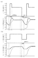
次に本実施の形態に係る加熱処理装置1の作用について、図4〜図6を参照しながら説明する。図5は、加熱室3内への搬入前後のウエハWの位置と加熱処理装置1の動作との関係を模式的に示した縦断面図であり、図6はヒータ34a、35aの設定温度とこれに対応する熱板34、35及び加熱室3内に搬入されたウエハWの温度とを示した説明図である。なおこれらの図においてはガス吐出部12や排気部61等の記載を省略してある。
Next, the effect | action of the
例えば馬蹄形状を備えた不図示のウエハ搬送機構によって搬送されてきたウエハWは、図5(a)に示すように冷却プレート4上に受け渡され待機する。ここでウエハWのPEB処理は例えば130℃にて行われるが、加熱室3内にウエハWを搬入する前の時点においては、例えば図6の時刻t0に示すように各ヒータ34a、35aは加熱処理温度よりも低い例えば100℃に設定されており、熱板34、35や加熱室3内も同じ温度になっている。
For example, the wafer W transferred by a wafer transfer mechanism (not shown) having a horseshoe shape is transferred to the
このような状態で冷却プレート4を下降させて、図5(b)に示すようにウエハWをワイヤ51A、51B上に受け渡し、ワイヤ51A、51Bを移動させてウエハWを先端部より加熱室3内に搬入する。ここで、側方にある開口部31より扁平な加熱室3内に、ほぼ水平に保持された状態でウエハWを搬入すると、ウエハWの先端が加熱室3に搬入される時刻(搬入開始時刻)t1とその後端が搬入される時刻(搬入完了時刻)t2との間には、図6に示すように例えば1〜3秒程度のずれが生じる。このためウエハWの先端側と後端側とで搬入のタイミングが異なると、加熱室3内で熱を吸収する時間が両部位の間で異なり、搬入を完了した時点におけるウエハWの表面には先端側の温度が高く、後端側の温度の低い温度差(温度分布)を生じることとなる。
In this state, the
このような温度分布を生じる原理をもう少し詳しく説明すると、図7(a)は、既述の冷却機構2を持たない、従来の加熱室にウエハWを搬入した場合におけるウエハW先端部、後端部夫々の温度変化の様子を示した模式図である。実線はウエハW先端部の温度変化を示し、破線は高端部の温度変化を示している。既に処理温度まで加熱されている加熱室内にウエハWの先端部が搬入されると、先端部の温度は処理温度となるまで図7(a)に実線で示す曲線を描いて上昇する。このとき、ウエハWの後端部は、ウエハWの先端側からの熱伝導により徐々に加熱されるが、熱板や加熱室内は既に処理温度となっているため、ウエハWの後端部が搬入された時点においては、既述のように3℃以上の例えば5℃という大きな温度分布を生じてしまう。このため、加熱室に搬入されたウエハWの後端側が先端側と同じペースで加熱されても、しばらくの間は温度分布の大きな状態が継続して、この間にウエハW面内におけるレジストパターンのばらつきを生じてしまう。
The principle of generating such a temperature distribution will be described in more detail. FIG. 7A shows the front end and rear end of the wafer W when the wafer W is loaded into a conventional heating chamber that does not have the
これに対して本実施の形態では、既述のようにヒータ34a、35bの設定温度を低く設定してあるため、この加熱室3内を加熱処理温度に維持した場合と比較して搬入されたウエハWの単位時間当たりの吸収熱量が小さくなる。この結果、搬入タイミングのずれにより生じる温度差を小さくすることができる。本実施の形態では、既述のように熱板34、35や加熱室3内の温度を100℃まで下げておくことにより、搬入完了時の時刻t2においてウエハW内に生じる温度差を3℃以下に抑えることが可能となっている。すなわちウエハWの後端部が搬入された時点における先端部後端部間の温度分布が小さいことにより、図7(b)に示すように温度分布の小さい状態のままウエハW全体を昇温して、ウエハW面内のレジストパターンのばらつきを小さくすることができる。
On the other hand, in this embodiment, since the set temperature of the
一方、ウエハW搬入時にヒータ34a、35bの設定温度を低く設定しておくことは、搬入完了後に熱板34、35を加熱処理温度まで昇温する工程を必要とし、ウエハWの搬入を完了してから加熱処理を終えるまでの加熱処理に要する時間が長くなってしまう場合が多い。そこで本実施の形態では、この昇温工程に要する時間を短縮するため、加熱室3へのウエハWの搬入を完了した状態において熱板34、35の急速昇温を行うようになっている。
On the other hand, setting the
この急速昇温工程の作用について説明すると、加熱室3内に搬入されたウエハWは、図5(c)に示すようにワイヤ51A、51B上に載置されたまま、いずれの熱板34、35にも接触しない状態でこれらの熱板34、35と対向する加熱処理位置に停止する。そして加熱処理装置1のバルブV1を開とし、加熱室3内と同じ温度に加熱されたパージ用のガスをガス吐出部12より加熱室3内に供給すると共に、バルブV2を開としてファン62を作動させガスを排気する。これによりウエハWの上下面には図4中に矢印で示す一方向流が形成され、熱板34、35からの熱放射やガスからの対流伝熱等により、ウエハWは搬入された高さ位置のままで加熱処理される。
Explaining the action of this rapid temperature raising step, the wafer W carried into the
このような動作と平行して加熱処理装置1は、図6に示すようにウエハWの搬入を完了したタイミングでヒータ34a、35aの設定温度を加熱処理温度よりも高い温度に昇温し、この状態を一定時間維持することにより、各熱板34、35及び加熱室3内を急速に昇温する。この結果ウエハW昇温速度が大きくなり、昇温工程に要する時間を短縮することができる。
In parallel with this operation, the
本実施の形態においては、急速昇温時のヒータ34a、35aの設定温度を例えば150℃とし、この状態を例えば15秒間維持している。このような急速昇温によって、ウエハWの搬入完了時刻t2から加熱処理を終えてウエハWの搬出を開始する時刻t4までに要する加熱処理時間を、加熱室3内の温度を変化させない従来の加熱処理に要する時間とほぼ同程度とすることができている。
In the present embodiment, the set temperature of the
次いで加熱処理装置1は、図6に示すように急速昇温の開始時刻t2より予め定めた時間を経過した時刻t3のタイミングにて急速昇温を終え、ヒータ34a、35aの設定値を加熱処理温度としてからこの状態を所定時間維持しウエハWの加熱処理を実行する。ここで時刻t2〜t3までの時間はウエハWの温度が加熱処理温度近くまで昇温されるタイミングに設定されている。以上に説明した工程によりウエハWに塗布された露光後の化学増幅型のレジスト膜が加熱されてPEB処理が行われる。
Then
こうしてウエハWの加熱処理を終える時刻t4となったら、パージ用ガスの供給と排気とを停止すると共に、搬入時とは逆の順序でウエハWを加熱室3より搬出する。そして図5(d)に示すようにワイヤ51A、51Bから冷却プレート4へと処理後のウエハWを受け渡して粗熱を取り除き、レジスト膜の酸反応を停止させた後、このウエハWを冷却プレート4より外部の搬送機構に受け渡して処理容器10外に搬出し、加熱処理装置1における処理を終了する。なお上述の例では、ウエハWの搬入、搬出のタイミングに合わせてパージ用のガスを供給、停止する場合について示したが、パージ用のガスは加熱処理装置1の稼動中、流したままの状態としておいてもよい。
After thus a time t 4 when completing the heat treatment of the wafer W, stops the exhaust and supply of the purge gas, the wafer W is unloaded from the
このように加熱処理を終えたウエハWを冷却、搬出する動作と平行して、加熱室3においては次のウエハWの搬入に備えて熱板34、35を冷却する作業が行われる。即ち、加熱室3からのウエハWの搬出を完了した時刻t5よりも後の時刻t6にて、ヒータ34a、35aの設定温度をウエハW搬入時の100℃まで低下させる降温操作を行う。なお、この急速冷却はウエハWの加熱処理を終了した時刻t4より開始するように構成してもよい。
In parallel with the operation of cooling and unloading the wafer W after the heat treatment in this way, in the
ここで、設定温度を変更するだけでは温度の低下する速度が遅いと、次のウエハWが搬入可能となる時刻までに熱板34、35や加熱室3内の温度が100℃に達しない場合も起こりうる。このような場合にはウエハWを加熱室3内に搬入できない待ち時間が発生してしまうため、本実施の形態では既述の冷却機構2を利用し、熱板34、35及び加熱室3内を急速冷却することにより、この待ち時間を生じさせないようになっている。
Here, if only the set temperature is changed and the rate of temperature decrease is slow, the temperature in the
この冷却機構2の作用について説明すると、図6に示したウエハWの搬出を完了した時刻t5にてバルブV3〜V5を開とし、図4、図5(d)に示すように冷媒供給源26より各冷却室21a、21b内に冷媒を供給する。これより熱板34、35や加熱室3内は急速冷却されて、次のウエハWが搬入される前に降温操作を完了させることができる。次いで降温操作を完了したタイミングの時刻t7において冷媒の供給を停止し、次のウエハWの搬入を待つ。これら図5(a)〜図5(d)の各工程を繰り返し実行することにより複数のウエハWに対するPEB処理が実行される。
To describe the operation of the
以上に説明した加熱処理装置1によれば以下のような効果がある。扁平な加熱室3の側方側の開口部31よりほぼ水平にウエハWを搬入する際に、この加熱室3内を加熱処理温度よりも低い温度に冷却しているので、このような降温操作をしていなかった従来の加熱処理装置に比べて搬入されたウエハWの先端側と後端側とに生じる温度差を小さくすることができる。この結果、例えばPEB処理時等にウエハW面内を均一に加熱することが可能となり、面内均一性の良好なレジストパターンを得られ、製品の歩留まり向上に貢献できる。
The
また、加熱室3内にウエハWを搬入してから加熱処理を行う温度まで昇温する工程において急速昇温を行ったり、ウエハWの熱処理を終えて加熱室3内を降温する工程において急速冷却を行ったりすることにより、これら昇温工程や降温工程に要する時間を短縮することが可能となる。この結果、加熱室3内の温度を変化させない従来法とほぼ同様の処理時間で各ウエハWの加熱処理を終えられるので、新たな工程を加えたことによるスループットの低下を防止できる。
Further, rapid heating is performed in the process of raising the temperature to the temperature at which the heat treatment is performed after the wafer W is loaded into the
また、熱板34、35を熱容量の小さなカーボン製の薄板とすることにより、急速昇温や急速冷却時等の温度変化に対する追随性をよくすることができる。ここで冷却機構2に使用する冷媒は、エア等のガスに限定されず、熱容量の大きな水などの液体を採用してもよい。また当該冷却手段の構成自体も、実施の形態に示した、冷媒と熱板34、35とを接触させて急速冷却を行うタイプのものに限定されない。例えば熱板34、35内に埋め込んだペルチェ素子を冷却手段としてもよい。この他、例えばステンレススチールよりなるウエハWと同程度の直径を有する熱容量の大きな厚板を加熱処理装置1内のウエハWの搬出入動作と干渉しない位置に載置しておき、この厚板を吸熱体として加熱室3内に搬入し、加熱室3内及び熱板34、35の温度を急速冷却するように構成してもよい。
Further, by making the
また熱板34、35の温度制御シーケンスは図6を用いて説明したパターンに限定されない。例えば図8(a)に示すように加熱処理を終えてから次のウエハWが搬入されるまでの期間中はヒータ34a、35aへの電力供給を停止して省エネルギーを図るようにしてもよい。また、ウエハWの処理時間や搬入間隔に余裕のある場合には、図8(b)に示すように急速昇温を行わない構成としてもよく、この反対に急速冷却を行わない構成としてもよい。更にまた、2枚の熱板34、35の一方だけを急速昇温、急速冷却するようにしてもよい。
Further, the temperature control sequence of the
更に、本実施の形態に係る加熱処理装置は熱板34、35の温度を運転中に変更可能に構成されているので、例えば図9に示すように製品ロットやレジストの種類の切り替え、運転条件の微調整等によりウエハWの加熱処理温度を変更する必要の生じた場合であっても装置を停止する等の特別な調整を必要とせずに加熱処理温度の変更を行うことができる。
Furthermore, since the heat treatment apparatus according to the present embodiment is configured so that the temperature of the
また加熱室3内に搬入されたウエハWの表面温度を計測する温度計を設置し、この温度計の計測結果に基づいて急速昇温の終了タイミングを決定するように構成してもよい。
Further, a thermometer for measuring the surface temperature of the wafer W carried into the
なお、実施の形態中においてはウエハWを搬送する搬送手段をウエハWの搬送路と交差する方向に張設されたワイヤ51A、51Bにより構成しているが、例えばウエハWの搬送路の両端にプーリを設け、これらのプーリを介して複数本のワイヤをウエハWの搬送方向に張設し、これらのワイヤによってウエハWを搬送するように構成してもよい。この場合には、冷却プレート4の溝部はワイヤに沿ってウエハWの搬送方向に設ける。
In the embodiment, the transfer means for transferring the wafer W is constituted by the
次に上述した加熱処理装置1を塗布、現像装置に適用した一例について簡単に説明する。図10は塗布、現像装置に露光装置が接続されたシステムの平面図であり、図11は同システムの斜視図である。図中S1はキャリアブロックであり、ウエハWが例えば13枚密閉収納されたキャリアC1を搬入出するための載置部121を備えたキャリアステーション120と、このキャリアステーション120から見て前方の壁面に設けられる開閉部122と、開閉部122を介してキャリアC1からウエハWを取り出すためのトランスファーアームCとが設けられている。
Next, an example in which the above-described
キャリアブロックS1の奥側には筐体124にて周囲を囲まれる処理ブロックS2が接続されており、処理ブロックS2には手前側から順に加熱・冷却系のユニットを多段化した棚ユニットP1、P2、P3及び液処理ユニットP4、P5と、搬送手段(メインアーム)A1、A2とが交互に設けられている。搬送手段A1、A2はこれら各ユニット間のウエハWの受け渡しを行う役割を果たす。搬送手段A1、A2は、キャリアブロックS1から見て前後方向に配置される棚ユニットP1、P2、P3の一面側と、右側の液処理ユニットP4、P5側の一面側と、左側の一面側をなす背面部とで構成される区画壁により囲まれる空間123内に置かれている。
A processing block S2 surrounded by a
棚ユニットP1、P2、P3は、液処理ユニットP4、P5にて行われる処理の前処理及び後処理を行うための各種ユニットを複数段積層した構成とされている。積層された各種ユニットにはウエハWを加熱(ベーク)する本実施の形態に係る複数の加熱ユニット(PAB、PEB)や、ウエハWを冷却する冷却ユニット等が含まれる。 The shelf units P1, P2, and P3 have a configuration in which various units for performing pre-processing and post-processing of the processing performed in the liquid processing units P4 and P5 are stacked in a plurality of stages. The stacked various units include a plurality of heating units (PAB, PEB) according to the present embodiment for heating (baking) the wafer W, a cooling unit for cooling the wafer W, and the like.
また液処理ユニットP4、P5は、化学増幅型のレジスト液や現像液等の薬液収納部の上に下部反射防止膜塗布ユニット133、レジスト塗布ユニット134、ウエハWに現像液を供給して現像処理する現像ユニット131等を複数段、例えば5段に積層して構成されている。
Further, the liquid processing units P4 and P5 supply a developing solution to the lower antireflection
インターフェイスブロックS3は、処理ブロックS2と露光装置S4との間に前後に設けられる第1の搬送室3A及び第2の搬送室3Bにより構成されており、夫々に昇降自在、鉛直軸回りに回転自在かつ進退自在なウエハ搬送機構131A、131Bを備えている。
The interface block S3 is composed of a
第1の搬送室3Aには、棚ユニットP6及びバッファカセットCOが設けられている。棚ユニットP6にはウエハ搬送機構131Aとウエハ搬送機構131Bとの間でウエハWの受け渡しを行うための受け渡しステージ(TRS)及び露光装置に受け渡す前にウエハWの温調を行う冷却プレートを有する高精度温調ユニット等が上下に積層された構成となっている。
In the
続いて、この塗布、現像装置におけるウエハWの流れについて説明する。先ず外部からウエハWの収納されたキャリアC1がキャリアブロックS1に搬入されると、ウエハWは、トランスファーアームC→棚ユニットP1の受け渡しユニット(TRS)→搬送手段A1→下部反射防止膜形成ユニット(BARC)133→搬送手段A1(A2)→加熱処理装置1(PAB)→搬送手段A1(A2)→冷却ユニット→搬送手段A1(A2)→レジスト塗布ユニット(COT)134→搬送手段A1(A2)→加熱処理装置1(PAB)→搬送手段A1(A2)→冷却ユニット→搬送手段A1→棚ユニットP3の受け渡しユニット(TRS)→ウエハ搬送機構131B→棚ユニットP6の受け渡しユニット(TRS)→棚ユニットP6の温調ユニット→ウエハ搬送機構131B→露光装置S4の順に搬送される。
Subsequently, the flow of the wafer W in the coating and developing apparatus will be described. First, when the carrier C1 in which the wafer W is stored from the outside is loaded into the carrier block S1, the wafer W is transferred from the transfer arm C → the transfer unit (TRS) of the shelf unit P1 → the transfer means A1 → the lower antireflection film forming unit ( BARC) 133 → Conveying means A1 (A2) → Heat treatment apparatus 1 (PAB) → Conveying means A1 (A2) → Cooling unit → Conveying means A1 (A2) → Resist coating unit (COT) 134 → Conveying means A1 (A2) → Heat treatment apparatus 1 (PAB) → Transfer means A1 (A2) → Cooling unit → Transfer means A1 → Delivery unit (TRS) of shelf unit P3 →
露光処理を受けたウエハWは、ウエハ搬送機構131B→棚ユニットP6の受け渡しステージ(TRS)→ウエハ搬送機構131A→棚ユニットP3の受け渡しユニット(TRS)→棚ユニットP3の加熱処理装置1(PEB)→搬送手段A2→現像ユニット131→搬送手段A1→棚ユニットP1の受け渡しユニット(TRS)→トランスファーアームCの順で搬送され、キャリアC1に戻されて塗布、現像処理が完了する。
The wafer W subjected to the exposure processing is transferred from the
(実験1)
図1〜図4にて説明したものとほぼ同様の構成の加熱処理装置1を用いてウエハWの加熱処理を行い、ウエハW平均温度及びウエハWの先後端間の温度差の経時変化を確認した。実験1では、熱板34、35が130℃の一定温度に加熱された加熱室3内に、12インチのウエハWを30cm/秒の速さで搬入し、上述の各温度の経時変化を計測した。
(Experiment 1)
The wafer W is heat-treated using the
実験1の結果を図12(a)に示す。図12(a)において、実線はウエハW平均温度の経時変化を示し、破線はウエハWの先後端間の温度差の経時変化を示している。図12(a)によれば、ウエハWの平均温度は加熱処理時間が長くなるにつれて漸増し、およそ120℃にてほぼ一定温度となっている。これに対してウエハWの先後端間の温度差は、搬入した直後の時点で約5℃近くまで跳ね上がった。
The result of
図12(b)は、この温度差の跳ね上がった時点におけるウエハW表面の温度分布を計測した結果である。図中、加熱室3への搬入方向に対して先端側を上、後端側を下とし、レジスト膜の形成されている上面側の温度分布を等温線により表した。各等温線の温度差は0.4℃刻みとなっており、各等温線で囲まれた領域は図中右側に付記した温度範囲にあることを示している。図12(b)の温度分布図からもわかるように、加熱室3に搬入されたウエハWの表面には、先に搬入されたウエハWの先端側の温度が高く、後から搬入された後端側の温度の低い温度分布が形成されることが分かる。このようなウエハW先後端間の温度差は、図12(a)の破線に示すように処理時間の経過と共に徐々に小さくなったが、ウエハWを搬入してから35秒程度の時間が経過するまでは1℃以下とならなかった。
FIG. 12B shows the result of measuring the temperature distribution on the surface of the wafer W when the temperature difference jumps. In the drawing, the temperature distribution on the upper surface side where the resist film is formed is represented by an isotherm with the front end side being the upper side and the rear end side being the lower side with respect to the loading direction into the
(実験2)
実験1と同様の加熱処理装置1を用い、熱板34、35の温度を変化させて搬入直後のウエハWの先後端間の温度差の変化を計測した。この他の条件は実験1と同様である。
(実施例) 熱板34、35の温度を105℃とした。
(比較例1)熱板34、35の温度を115℃とした。
(比較例2)熱板34、35の温度を130℃とした。
(Experiment 2)
Using the same
(Example) The temperature of the
(Comparative example 1) The temperature of the
(Comparative example 2) The temperature of the
実験2の結果を図13に示す。図13は、ウエハW搬入時の熱板34、35の温度に対して、搬入直後のウエハW先後端間の温度差をプロットした結果と、これらのプロットをもとに描いた近似曲線とを示している。実施例では、ウエハWの先後端間の温度差は約3℃であったのに対し、比較例1では約3.5℃、実施例2では約4.5℃となった。発明者らはウエハW面内で均一な線幅のレジストパターンを得るために、この温度差を3℃以下とすることを目標としている。図13に示した近似曲線によれば、本実験で使用した加熱処理装置1では、ウエハW搬入時の熱板34、35及び加熱室3内の温度をおよそ100℃以下としておくことで、搬入直後のウエハWの温度差を3℃以下にできるといえる。
The result of
W ウエハ
1 加熱処理装置
2 冷却機構
3 加熱室
4 冷却プレート
5 搬送手段
7 制御部
10 処理容器
10a 搬入出口
10c シャッタ
11 基台
12 ガス吐出部
12a 吐出口
13 ガス供給源
13a ガス供給管
14 伝熱板
14a ヒートパイプ
21a、21b
冷却室
22a、22b
冷媒供給管
23a、23b
冷媒排気管
24 噴出し口
25 排気口
26 冷媒供給源
31 開口部
32 側壁部
33 隙間部
34、35 熱板
34a、35a
ヒータ
36 ヒータコントローラ
41 溝部
42 昇降機構
43 支持ピン
44 切り欠き部
51A、51B
ワイヤ
52A、52B
ワイヤ支持部
53 移動機構
54 基体
55A、55B
ガイドレール
56 駆動部
57 ビーズ部材
58 遮蔽板
61 排気部
61a 排気口
62 ファン
63 排気管
Cooling
Claims (12)
この加熱室内に、基板と対向するように設けられた加熱処理用の熱板と、
この熱板を加熱するための加熱手段と、
前記熱板を冷却するための冷却手段と、
前記処理容器内に設けられ、前記加熱室の開口部と隣接する待機位置と、前記熱板に対向する加熱処理位置と、の間で基板を搬送する搬送手段と、
一の基板の加熱処理を終えた後、次の基板が前記加熱室内に搬入される前に熱板を降温させるように前記冷却手段を制御し、次の基板を前記加熱室内に搬入した後、加熱処理温度まで熱板を昇温するように前記加熱手段を制御する動作を、加熱処理される基板毎に繰り返す制御手段と、を備えたことを特徴とする加熱処理装置。 A heating chamber for performing a post-exposure heat treatment on the resist film formed on the surface of the substrate provided in the processing vessel and carried almost horizontally from the side opening.
In this heating chamber, a heat treatment hot plate provided to face the substrate,
Heating means for heating the hot plate;
Cooling means for cooling the hot plate;
A transport unit provided in the processing container and transporting the substrate between a standby position adjacent to the opening of the heating chamber and a heat processing position facing the hot plate;
After finishing the heat treatment of one substrate, the cooling means is controlled to lower the temperature of the hot plate before the next substrate is carried into the heating chamber, and after the next substrate is carried into the heating chamber, A heat treatment apparatus comprising: control means for repeating the operation of controlling the heating means to raise the temperature of the hot plate to a heat treatment temperature for each substrate to be heat treated.
前記加熱室に設けられた熱板により、前記加熱室に搬入された基板の表面に形成されたレジスト膜に対し、露光後の加熱処理をする工程と、
一の基板の加熱処理を終えた後、次の基板が前記加熱室に搬入される前に熱板を降温させる工程と、
次の基板を前記加熱室内に搬入した後、加熱処理温度まで熱板を昇温する工程と、を含み、これら熱板を降温させる工程、及び熱板を昇温する工程を、加熱処理される基板毎に繰り返すことを特徴とする基板の加熱処理方法。 A step of loading the substrate substantially horizontally from the opening on the side of the heating chamber provided in the processing container;
The hot plate provided in the heating chamber, the relative heating chamber to carry resist film formed on the surface of the substrate, a step of heat treatment after exposure,
A step of lowering the temperature of the hot plate after the heat treatment of one substrate is finished and before the next substrate is carried into the heating chamber;
After loading the next substrate in said heating chamber, viewed including the steps of hot plate the temperature is raised to the heating temperature, the step is lowered them hot plate, and a step of heating the hot plate, heat treated A method for heat-treating a substrate, which is repeated for each substrate .
前記コンピュータプログラムは、請求項8ないし11の何れか一つに記載された加熱処理方法を実施するようにステップ群が組まれていることを特徴とする記憶媒体。 Used in a heating apparatus provided with a heating chamber provided in a processing container and having an opening for loading and unloading a substrate from the side and a hot plate provided to heat the substrate from below. A storage medium storing a computer program to be recorded,
A storage medium, wherein the computer program includes a group of steps so as to implement the heat treatment method according to any one of claims 8 to 11 .
Priority Applications (3)
| Application Number | Priority Date | Filing Date | Title |
|---|---|---|---|
| JP2007021355A JP4840168B2 (en) | 2007-01-31 | 2007-01-31 | Heating device, heating method and storage medium |
| US12/020,898 US20080182217A1 (en) | 2007-01-31 | 2008-01-28 | Heating device, heating method and storage medium |
| KR1020080009606A KR20080071929A (en) | 2007-01-31 | 2008-01-30 | Heating apparatus, heating method and storage medium |
Applications Claiming Priority (1)
| Application Number | Priority Date | Filing Date | Title |
|---|---|---|---|
| JP2007021355A JP4840168B2 (en) | 2007-01-31 | 2007-01-31 | Heating device, heating method and storage medium |
Publications (2)
| Publication Number | Publication Date |
|---|---|
| JP2008187126A JP2008187126A (en) | 2008-08-14 |
| JP4840168B2 true JP4840168B2 (en) | 2011-12-21 |
Family
ID=39668398
Family Applications (1)
| Application Number | Title | Priority Date | Filing Date |
|---|---|---|---|
| JP2007021355A Active JP4840168B2 (en) | 2007-01-31 | 2007-01-31 | Heating device, heating method and storage medium |
Country Status (3)
| Country | Link |
|---|---|
| US (1) | US20080182217A1 (en) |
| JP (1) | JP4840168B2 (en) |
| KR (1) | KR20080071929A (en) |
Families Citing this family (7)
| Publication number | Priority date | Publication date | Assignee | Title |
|---|---|---|---|---|
| JP4519037B2 (en) * | 2005-08-31 | 2010-08-04 | 東京エレクトロン株式会社 | Heating device and coating / developing device |
| JP5316135B2 (en) * | 2009-03-19 | 2013-10-16 | ウシオ電機株式会社 | Exposure equipment |
| JP4977747B2 (en) | 2009-12-10 | 2012-07-18 | 東京エレクトロン株式会社 | Substrate processing method, program, computer storage medium, and substrate processing system |
| JP6240440B2 (en) * | 2013-08-30 | 2017-11-29 | 東京応化工業株式会社 | Chamber apparatus and heating method |
| JP6211886B2 (en) * | 2013-10-15 | 2017-10-11 | 東京エレクトロン株式会社 | Heat treatment method and heat treatment apparatus |
| JP6926765B2 (en) * | 2017-07-19 | 2021-08-25 | 東京エレクトロン株式会社 | Substrate heating device and substrate heating method |
| GB2610156A (en) * | 2021-04-29 | 2023-03-01 | Edwards Ltd | Semiconductor processing system |
Family Cites Families (16)
| Publication number | Priority date | Publication date | Assignee | Title |
|---|---|---|---|---|
| JP4330717B2 (en) * | 1999-08-09 | 2009-09-16 | 東京エレクトロン株式会社 | Hot plate unit and method of using hot plate unit |
| JPS5823722B2 (en) * | 1978-12-25 | 1983-05-17 | ティーディーケイ株式会社 | Manufacturing method of voltage nonlinear resistor porcelain |
| JPH01111329A (en) * | 1987-10-26 | 1989-04-28 | Toshiba Corp | Controller for resist curing device |
| JPH0268921A (en) * | 1988-09-02 | 1990-03-08 | Tokyo Electron Ltd | Resist treatment device |
| JPH03201424A (en) * | 1989-12-28 | 1991-09-03 | Tokyo Erekutoron Kyushu Kk | Temperature controller |
| EP0827186A3 (en) * | 1996-08-29 | 1999-12-15 | Tokyo Electron Limited | Substrate treatment system |
| JPH11173774A (en) * | 1997-12-05 | 1999-07-02 | Komatsu Ltd | Plate type heat pipe and temperature controller using it |
| JP2001230199A (en) * | 1999-07-28 | 2001-08-24 | Komatsu Ltd | Temperature controller for semiconductor substrate and heat exchange plate |
| US6600138B2 (en) * | 2001-04-17 | 2003-07-29 | Mattson Technology, Inc. | Rapid thermal processing system for integrated circuits |
| US6887803B2 (en) * | 2001-11-08 | 2005-05-03 | Wafermasters, Inc. | Gas-assisted rapid thermal processing |
| KR100974141B1 (en) * | 2002-11-28 | 2010-08-04 | 도쿄엘렉트론가부시키가이샤 | Wafer processing apparatus |
| JP2005093949A (en) * | 2003-09-19 | 2005-04-07 | Dainippon Screen Mfg Co Ltd | Temperature regulator, temperature regulation system, and substrate processing apparatus |
| EP1647789A1 (en) * | 2004-10-04 | 2006-04-19 | Ngk Insulators, Ltd. | Continuous heat treatment furnace and heat treatment method |
| JP4852852B2 (en) * | 2005-02-17 | 2012-01-11 | ウシオ電機株式会社 | Heating unit |
| JP4535499B2 (en) * | 2005-04-19 | 2010-09-01 | 東京エレクトロン株式会社 | Heating device, coating, developing device and heating method |
| JP4606355B2 (en) * | 2006-03-14 | 2011-01-05 | 東京エレクトロン株式会社 | Heat treatment apparatus, heat treatment method and storage medium |
-
2007
- 2007-01-31 JP JP2007021355A patent/JP4840168B2/en active Active
-
2008
- 2008-01-28 US US12/020,898 patent/US20080182217A1/en not_active Abandoned
- 2008-01-30 KR KR1020080009606A patent/KR20080071929A/en active Search and Examination
Also Published As
| Publication number | Publication date |
|---|---|
| JP2008187126A (en) | 2008-08-14 |
| US20080182217A1 (en) | 2008-07-31 |
| KR20080071929A (en) | 2008-08-05 |
Similar Documents
| Publication | Publication Date | Title |
|---|---|---|
| JP4788610B2 (en) | Heating device, coating, developing device, heating method and storage medium | |
| JP4840168B2 (en) | Heating device, heating method and storage medium | |
| US7797855B2 (en) | Heating apparatus, and coating and developing apparatus | |
| JP5195711B2 (en) | Substrate cooling device, substrate cooling method, and storage medium | |
| JP5101665B2 (en) | Substrate mounting table, substrate processing apparatus, and substrate processing system | |
| JP4699283B2 (en) | Heat treatment plate temperature control method, program, and heat treatment plate temperature control device | |
| KR102503838B1 (en) | Substrate heating device | |
| KR101227809B1 (en) | Method for reducing temperature of substrate placing table, computer-readable storage medium, and substrate processing system | |
| JP2006273563A (en) | Load lock device, processing system, and processing method | |
| KR20070122390A (en) | Substrate treatment method and apparatus | |
| KR101667434B1 (en) | Heat treatment apparatus, heat treatment method and recording medium | |
| JP3910791B2 (en) | Substrate heat treatment method and substrate heat treatment apparatus | |
| JP6447328B2 (en) | Heating device | |
| JP2013026509A (en) | Heat treatment apparatus | |
| US20060110944A1 (en) | Dummy substrate for thermal reactor | |
| JP4519036B2 (en) | Heating device, coating, developing device and heating method | |
| JP2004235469A (en) | Heat treatment method and heat treatment apparatus | |
| JP7200638B2 (en) | Heat treatment apparatus and heat treatment method | |
| JPH1163838A (en) | Hybrid heat treatment apparatus | |
| KR102282145B1 (en) | Apparatus and Method for treating substrate | |
| JPH1022189A (en) | Substrate heat-treating device | |
| CN109285797B (en) | Substrate heating apparatus and substrate heating method | |
| JP2003124134A (en) | System and method for heat treatment | |
| JP2001230201A (en) | Device and method for heating and cooling and substrate treating apparatus | |
| JP2008166658A (en) | Heat treatment apparatus |
Legal Events
| Date | Code | Title | Description |
|---|---|---|---|
| A621 | Written request for application examination |
Free format text: JAPANESE INTERMEDIATE CODE: A621 Effective date: 20090209 |
|
| A131 | Notification of reasons for refusal |
Free format text: JAPANESE INTERMEDIATE CODE: A131 Effective date: 20110412 |
|
| A521 | Request for written amendment filed |
Free format text: JAPANESE INTERMEDIATE CODE: A523 Effective date: 20110613 |
|
| TRDD | Decision of grant or rejection written | ||
| A01 | Written decision to grant a patent or to grant a registration (utility model) |
Free format text: JAPANESE INTERMEDIATE CODE: A01 Effective date: 20110906 |
|
| A01 | Written decision to grant a patent or to grant a registration (utility model) |
Free format text: JAPANESE INTERMEDIATE CODE: A01 |
|
| A61 | First payment of annual fees (during grant procedure) |
Free format text: JAPANESE INTERMEDIATE CODE: A61 Effective date: 20110919 |
|
| R150 | Certificate of patent or registration of utility model |
Ref document number: 4840168 Country of ref document: JP Free format text: JAPANESE INTERMEDIATE CODE: R150 Free format text: JAPANESE INTERMEDIATE CODE: R150 |
|
| FPAY | Renewal fee payment (event date is renewal date of database) |
Free format text: PAYMENT UNTIL: 20141014 Year of fee payment: 3 |
|
| R250 | Receipt of annual fees |
Free format text: JAPANESE INTERMEDIATE CODE: R250 |
|
| R250 | Receipt of annual fees |
Free format text: JAPANESE INTERMEDIATE CODE: R250 |
|
| R250 | Receipt of annual fees |
Free format text: JAPANESE INTERMEDIATE CODE: R250 |
|
| R250 | Receipt of annual fees |
Free format text: JAPANESE INTERMEDIATE CODE: R250 |
|
| R250 | Receipt of annual fees |
Free format text: JAPANESE INTERMEDIATE CODE: R250 |