JP4839298B2 - Image processing apparatus, image processing apparatus control method, program, and storage medium - Google Patents
Image processing apparatus, image processing apparatus control method, program, and storage medium Download PDFInfo
- Publication number
- JP4839298B2 JP4839298B2 JP2007307895A JP2007307895A JP4839298B2 JP 4839298 B2 JP4839298 B2 JP 4839298B2 JP 2007307895 A JP2007307895 A JP 2007307895A JP 2007307895 A JP2007307895 A JP 2007307895A JP 4839298 B2 JP4839298 B2 JP 4839298B2
- Authority
- JP
- Japan
- Prior art keywords
- color
- image
- unit
- data
- processing apparatus
- Prior art date
- Legal status (The legal status is an assumption and is not a legal conclusion. Google has not performed a legal analysis and makes no representation as to the accuracy of the status listed.)
- Expired - Fee Related
Links
Images


Classifications
-
- H—ELECTRICITY
- H04—ELECTRIC COMMUNICATION TECHNIQUE
- H04N—PICTORIAL COMMUNICATION, e.g. TELEVISION
- H04N1/00—Scanning, transmission or reproduction of documents or the like, e.g. facsimile transmission; Details thereof
- H04N1/23—Reproducing arrangements
- H04N1/2307—Circuits or arrangements for the control thereof, e.g. using a programmed control device, according to a measured quantity
- H04N1/2315—Circuits or arrangements for the control thereof, e.g. using a programmed control device, according to a measured quantity according to characteristics of the reproducing apparatus, e.g. capability
-
- H—ELECTRICITY
- H04—ELECTRIC COMMUNICATION TECHNIQUE
- H04N—PICTORIAL COMMUNICATION, e.g. TELEVISION
- H04N1/00—Scanning, transmission or reproduction of documents or the like, e.g. facsimile transmission; Details thereof
- H04N1/23—Reproducing arrangements
- H04N1/2307—Circuits or arrangements for the control thereof, e.g. using a programmed control device, according to a measured quantity
- H04N1/2361—Selecting a particular reproducing device from amongst a plurality of devices, e.g. high or low resolution devices
-
- H—ELECTRICITY
- H04—ELECTRIC COMMUNICATION TECHNIQUE
- H04N—PICTORIAL COMMUNICATION, e.g. TELEVISION
- H04N1/00—Scanning, transmission or reproduction of documents or the like, e.g. facsimile transmission; Details thereof
- H04N1/32—Circuits or arrangements for control or supervision between transmitter and receiver or between image input and image output device, e.g. between a still-image camera and its memory or between a still-image camera and a printer device
- H04N1/32502—Circuits or arrangements for control or supervision between transmitter and receiver or between image input and image output device, e.g. between a still-image camera and its memory or between a still-image camera and a printer device in systems having a plurality of input or output devices
- H04N1/32523—Circuits or arrangements for control or supervision between transmitter and receiver or between image input and image output device, e.g. between a still-image camera and its memory or between a still-image camera and a printer device in systems having a plurality of input or output devices a plurality of output devices
- H04N1/32539—Detecting or indicating the status of the output devices
-
- H—ELECTRICITY
- H04—ELECTRIC COMMUNICATION TECHNIQUE
- H04N—PICTORIAL COMMUNICATION, e.g. TELEVISION
- H04N1/00—Scanning, transmission or reproduction of documents or the like, e.g. facsimile transmission; Details thereof
- H04N1/40—Picture signal circuits
- H04N1/40006—Compensating for the effects of ageing, i.e. changes over time
Description
本発明は、画像処理技術に関するものである。 The present invention relates to an image processing technique.
トナーを用いた電子写真方式のデバイスは経時変化の影響を受けやすい。そのため色再現性の高さを売りとしているハイエンド機であっても、時間が経つと新品のオフィス機よりも色再現性が悪くなる現象が起こる。従来ではこの問題を解決するため、ユーザは任意のタイミングでキャリブレーションを実行し、経時変化による色再現性の変動量を吸収するための色補正をしていた。キャリブレーションによる色補正を行う場合であっても、ユーザがどのタイミングでキャリブレーションを行えば良いかを判断できないという問題が生じる。 Electrophotographic devices using toner are susceptible to changes over time. Therefore, even for high-end machines that sell high color reproducibility, the phenomenon of color reproducibility worse than that of a new office machine occurs over time. Conventionally, in order to solve this problem, the user executes calibration at an arbitrary timing, and performs color correction to absorb the amount of change in color reproducibility due to changes over time. Even in the case of performing color correction by calibration, there arises a problem that the user cannot determine at which timing calibration should be performed.
キャリブレーションを実行するタイミングを特定するために、キャリブレーションを行った時刻を記録しておき、前回のキャリブレーションからの経過時間と、色再現性の変動量とを求める技術がある。例えば、特許文献1では、経過時間や色再現性の変動量に応じてキャリブレーションをユーザに促す技術が提案されている。
In order to specify the timing for executing calibration, there is a technique in which the time at which calibration is performed is recorded and the elapsed time from the previous calibration and the amount of change in color reproducibility are obtained. For example,
また、近年電子写真デバイスの低価格化や省スペース化が進むことで1つのオフィスで複数台のデバイスを導入すること例が増大している。同時に、ネットワーク技術の発達により、ユーザが出力するデバイスを自由に選択できるシステムが構築可能となっている。
しかしながら、従来のネットワーク環境ではユーザが任意のタイミングで処理を行うことを前提としている。そのため、ユーザがデータを出力する際に対象となったデバイスが必ずしも最適な色再現性を実現できない可能性がある。特に経時変化に対する変動量はデバイスに応じて異なり、例え色再現性の良いハイエンド機であっても色の変動量が大きい場合や、ハイエンド機に比べて、色再現性の悪いオフィス機であっても色の変動そのものは小さい場合がある。 However, in the conventional network environment, it is assumed that the user performs processing at an arbitrary timing. Therefore, there is a possibility that the device targeted when the user outputs data cannot always realize the optimum color reproducibility. In particular, the amount of change with time varies depending on the device.For example, even if a high-end machine with good color reproducibility has a large amount of color fluctuation, or an office machine with poor color reproducibility compared to a high-end machine. However, the color variation itself may be small.
また、各デバイスの変動量は色に応じて異なる。電子写真方式のデバイスでは、例えば、シアン、マゼンタ、イエロー、ブラックといった異なる色材を用いるため、それぞれ経時変化による劣化度も異なる。また、それらを混色させると単色のものに比べて変動量は変化する。このように色に応じてデバイスの変動量が異なるということは、ユーザが出力したい原稿の持つ色分布によっても最適なデバイスが異なることになる。 In addition, the variation amount of each device differs depending on the color. In an electrophotographic device, for example, different color materials such as cyan, magenta, yellow, and black are used. Also, when they are mixed, the amount of change changes compared to a single color. Thus, the fact that the amount of device variation varies depending on the color means that the optimum device varies depending on the color distribution of the document that the user wants to output.
このため、ユーザは、原稿のコピーやデータ出力をする際に最適なデバイスがわからず、ネットワーク上のリソースを有効に活用できないという問題がある。 For this reason, there is a problem that the user cannot know the optimum device when copying a document or outputting data, and cannot effectively use resources on the network.
本発明は、出力するデータに適したデバイスを定量的に評価し、リソースを有効に活用することを可能にする画像処理技術の提供を目的とする。 An object of the present invention is to provide an image processing technique that enables a device suitable for output data to be quantitatively evaluated and resources to be effectively used.
本発明に係る画像処理装置は、画像データの出力が可能な複数の画像形成デバイスそれぞれの画質の変動量を、キャリブレーション実行時の画像形成の結果と、当該キャリブレーション実行後の画像形成の結果と、に基づき補間する補間手段と、
前記補間手段による前記補間の結果に基づき、出力すべき画像データに対する画質の変動量を前記複数の画像形成デバイスそれぞれに対して算出する算出手段と、
前記算出手段の算出結果に基づき、前記画像データの出力先として前記複数の画像形成デバイスの優先順位を決定する決定手段と、
前記決定手段により決定された前記優先順位に従って、前記複数の画像形成デバイスの中から選択が可能な画像形成デバイスをリスト表示する表示手段と
を備えることを特徴とする。
The image processing apparatus according to the present invention includes a result of image formation at the time of executing calibration and a result of image formation after the execution of calibration, for each of a plurality of image forming devices capable of outputting image data. Interpolating means for performing interpolation based on
Based on the result of the interpolation by the interpolation means, a calculation means for calculating a variation amount of image quality for the image data to be output for each of the plurality of image forming devices;
A determining unit that determines a priority order of the plurality of image forming devices as an output destination of the image data based on a calculation result of the calculating unit;
Display means for displaying a list of image forming devices that can be selected from the plurality of image forming devices according to the priority order determined by the determining means.
あるいは、本発明に係る画像処理装置の制御方法は、補間手段が、画像データの出力が可能な複数の画像形成デバイスそれぞれの画質の変動量を、キャリブレーション実行時の画像形成の結果と、当該キャリブレーション実行後の画像形成の結果と、に基づき補間する補間工程と、
算出手段が、前記補間工程による前記補間の結果に基づき、出力すべき画像データに対する画質の変動量を前記複数の画像形成デバイスそれぞれに対して算出する算出工程と、
決定手段が、前記算出工程の算出結果に基づき、前記画像データの出力先として前記複数の画像形成デバイスの優先順位を決定する決定工程と、
表示手段が、前記決定工程により決定された前記優先順位に従って、前記複数の画像形成デバイスの中から選択が可能な画像形成デバイスをリスト表示する表示工程と
を有することを特徴とする。
Alternatively, in the control method of the image processing apparatus according to the present invention, the interpolation means calculates the variation amount of the image quality of each of the plurality of image forming devices capable of outputting image data, the image formation result at the time of calibration execution, An interpolation process for performing interpolation based on the result of image formation after calibration execution;
A calculating step in which a calculating unit calculates a variation amount of image quality for image data to be output for each of the plurality of image forming devices based on the result of the interpolation in the interpolation step;
A determination unit that determines a priority order of the plurality of image forming devices as an output destination of the image data based on a calculation result of the calculation step;
Display means, in accordance with the priority determined by said determining step, characterized in that it has a display step of listing the image forming device capable of selective from among the plurality of image forming devices.
本発明によれば、出力するデータに適したデバイスを定量的に評価し、リソースを有効に活用することが可能になる。 According to the present invention, it is possible to quantitatively evaluate a device suitable for data to be output and effectively use resources.
以下、図面を参照して、本発明の好適な実施形態を例示的に詳しく説明する。ただし、この実施の形態に記載されている構成要素はあくまで例示であり、本発明の技術的範囲は、特許請求の範囲によって確定されるのであって、以下の個別の実施形態によって限定されるわけではない。 Hereinafter, exemplary embodiments of the present invention will be described in detail with reference to the drawings. However, the constituent elements described in this embodiment are merely examples, and the technical scope of the present invention is determined by the scope of claims, and is limited by the following individual embodiments. is not.
図1は複数台のカラー複合機(multi-function peripheral:MFP)をネットワークに接続したシステムの構成図である。オフィスカラーMFP101、ハイエンドカラーMFP102、オフィスカラーMFP103、オフィスカラーMFP104、及び情報処理装置(PC)105がネットワーク106に接続されている。このシステムによりユーザは、リモートコピー環境111とドライバ出力環境112とを利用することができる。
FIG. 1 is a configuration diagram of a system in which a plurality of multi-function peripherals (MFPs) are connected to a network. An office color MFP 101, a high-
リモートコピー環境111では、例えば、オフィスカラーMFP101のスキャナ機能の利用で原稿107を取り込む。そして、取り込んだ原稿107のデータをハイエンドカラーMFP102、オフィスカラーMFP103、オフィスカラーMFP104へ出力可能である。
In the
また、ドライバ出力環境112では、例えば、PC105が備えるプリンタドライバを用いてデータ108をオフィスカラーMFP101へ出力可能である。また、PC105が備えるプリンタドライバを用いてデータ108をハイエンドカラーMFP102、オフィスカラーMFP103、オフィスカラーMFP104へ出力することも可能である。
In the
本発明の実施形態にかかる画像処理装置等は、上述のオフィスカラーMFP101、ハイエンドカラーMFP102、オフィスカラーMFP103、オフィスカラーMFP104等の画像形成装置に適用することが可能である。
The image processing apparatus according to the embodiment of the present invention can be applied to the image forming apparatuses such as the office color MFP 101, the high-
(第1実施形態)
第1実施形態ではカラーMFPを対象にリモートコピー処理において画像形成デバイス(以下、単に「デバイス」という)を画質の変動量の少ないデバイス順に表示する処理について説明する。
(First embodiment)
In the first embodiment, a process for displaying image forming devices (hereinafter simply referred to as “devices”) in order of devices with the smallest image quality variation in remote copy processing for a color MFP will be described.
図2はカラーMFPの機能構成に関するブロック図である。図2においてオートドキュメントフィーダーを含む画像読み取り部201は、複数枚の原稿画像、あるいは一枚の原稿画像を図示しない光源からの照射光で照射する。そして、画像読み取り部201は、原稿画像からの反射光に基づく反射像をレンズを介して撮像素子上に結像させる。そして、画像読み取り部201は、撮像素子からラスター状の画像読み取り信号(画像信号)をイメージ情報として得る。
FIG. 2 is a block diagram relating to the functional configuration of the color MFP. In FIG. 2, an
データ処理部205は、この画像信号に基づいて種々の画像処理を実行して、画像信号を画像形成のための記録信号に変換する。記録部203は、データ処理部205から記録信号を受け付けると、記録信号に基づき印刷用紙上に画像を形成し、出力する。この流れが通常の複写機能によるコピー動作である。記録部203はカラーMFPの場合、C、M、Y、Kの色材による画像形成を実行することが可能であり、データ処理部205で処理されたデータ(記録信号)に基づき画像形成動作を実行する。尚、本発明の趣旨は、カラーMFPに対するものに限定されず、モノクロMFPに対しても同様に適用することが可能であることは言うまでもない。
The
操作者はカラーMFPに装備されたキー操作部である入力部206を介してカラーMFPを操作することが可能である。入力部206が受け付けた操作者からの指示は、データ処理部205に入力される。データ処理部205は、入力部206が受け付けた操作者からの指示に従って、画像形成のための記録信号の変換処理を制御することが可能である。データ処理部205には、不図示の制御手段として機能することが可能なCPUが備えられており、CPUは、カラーMFPの動作を全体的に管理し、制御することが可能である。
An operator can operate the color MFP via the
表示部204は、カラーMFPの状態、キャリブレーションの要否、操作入力の状態表示及び処理中の画像データ(カラー画像データ、モノクロ画像データ)に関する情報を表示することが可能である。CPUは、表示部204に種々のデータを表示するための表示制御手段として機能する。
The
記憶部202は、画像読み取り部201で取り込んだ画像データ等を保存することが可能な領域である。記憶部202は、画像データの他、キャリブレーション経過時間や、キャリブレーション経過時間を基準とした場合の画質のずれ(以下、「変動量」ともいう)、例えば、色味の変動量などの情報を格納することができる。記憶部202は、更に、CPUのワークエリアとして機能することが可能であり、CPUによる補正量の演算結果を記憶部202に格納することも可能である。ネットワークインタフェース(I/F)207はネットワーク106とカラーMFPとを接続するためのインターフェースである。ネットワークインタフェース(I/F)207を用いることで、ネットワーク上の情報処理装置等から画像データを受け取ることが可能になる。ネットワークインタフェース(I/F)207を介して受信された画像データは、データ処理部205により処理され、記録部203により画像形成され、印刷出力される。
The
また、画像読み取り部201で原稿107を読み取り、データ処理部205で処理されたデータをネットワークI/F207を介してネットワーク上の情報処理装置に送信することも可能である。リモートコピー環境を利用する場合、画像読み取り部201で原稿107を読み取り、データ処理部205で処理されたデータをネットワークI/F207を介して送信する。そして、ネットワーク106に接続する他のカラーMFPの持つ記録部で画像形成処理を行うことも可能である。
It is also possible to read the original 107 by the
(スキャナ画像処理)
次に、データ処理部205が実行する画像処理について図3を用いて説明する。画像読み取り部201の一部であるスキャナを用いて画像データ(原稿)が取り込まれる(S301)。データ処理部205は、画像データに基づいて、デバイスの機種ごとに対応したデバイス依存RGBの形式でデータを取得する(S302)。
(Scanner image processing)
Next, image processing executed by the
次にステップS303において、データ処理部205は、色変換処理1(第1色変換処理)を行う。ステップS304において、データ処理部205は、デバイスに依存したRGBデータを、デバイスに依存しない共通RGBデータに変換する。データ処理部205は、例えば、デバイスそれぞれに共通のL*a*b*色空間に変換することでデバイス依存RGB形式のデータを共通RGBデータに変換することができる。
In step S303, the
色変換処理の終了後に、ステップS305で記憶部202に共通RGBデータが格納される。S301〜S304までは読み込んだ画像データの処理に関するものであるため、S301〜S304を総称して「スキャナ画像処理」と定義する。
After the color conversion process is completed, the common RGB data is stored in the
(プリンタ画像処理)
次に、ステップS307にて、データ処理部205は記憶部202に格納された共通RGBデータを読み出して、ステップS308で色変換処理2(第2色変換処理)を実行し、CMYK(多値)データを生成する(S309)。
(Printer image processing)
Next, in step S307, the
次に、データ処理部205はガンマ補正(S310)、スクリーン処理を行い(S311)、CMYK(二値)データを生成する(S312)。データ処理部205はCMYK(二値)データを記録部203に送信し、記録部203の一部を構成するプリンタにより印刷処理が実行される(S313)。S308〜S313までの処理は記録部203の一部を構成するプリンタに関するものであるため、S308〜S313を総称して「プリンタ画像処理」と定義する。
Next, the
(ドライバ画像処理)
上述の例では、コピー処理の場合を例として挙げたが、S315〜S318では、情報処理装置(PC)のドライバ出力の流れを説明する。
(Driver image processing)
In the above example, the case of copy processing has been described as an example. In S315 to S318, the flow of driver output of the information processing apparatus (PC) will be described.
S315において、画像データがPCで生成され、この画像データをsRGB(standard RGB)として処理する(S316)。そしてCMS(Color Management System)によって画像データに対する色変換が行われ(S317)、CMYK(多値)データが生成される(S318)。生成されたCMYK(多値)データは記憶部202に格納される(S319)。以上説明したS315〜S318の処理を総称して「ドライバ画像処理」と定義する。 In S315, image data is generated by the PC, and this image data is processed as sRGB (standard RGB) (S316). Then, color conversion is performed on the image data by CMS (Color Management System) (S317), and CMYK (multi-value) data is generated (S318). The generated CMYK (multi-value) data is stored in the storage unit 202 (S319). The processes of S315 to S318 described above are collectively referred to as “driver image processing”.
その後、記憶部202に格納されたCMYK(多値)データは、S321で読み出され、プリンタ画像処理で説明したガンマ補正(S310)、スクリーン処理(S311)、CMYK(二値)データの生成(S312)処理が実行される。そして、CMYK(二値)データは、記録部203に送信され、記録部203の一部を構成するプリンタにより印刷処理が実行される(S313)。
Thereafter, the CMYK (multi-value) data stored in the
オフィスカラーMFP101からハイエンドカラーMFP102に対してリモートコピーを実行する場合、オフィスカラーMFP101が備えるスキャナで取り込んだ画像データに対して、スキャナ画像処理が施される(S301〜S304)。スキャナ画像処理により生成された共通RGBデータは、ハイエンドカラーMFP102の記憶部202に格納される(S305)。ハイエンドカラーMFP102において、共通RGBデータに対するプリンタ画像処理が実行され、プリンタ画像処理の結果が印刷出力される(S308〜S313)。
When remote copy is executed from the
(キャリブレーション処理)
次に、データ処理部205で行われるキャリブレーション処理について説明する。図4(a)〜(c)はキャリブレーション処理について説明する図である。図4(a)及び図4(c)は入力された信号値に対するプリント出力の濃度特性の関係を示す図であり、CMYKの色ごとに独立した関係を有する。
(Calibration process)
Next, the calibration process performed by the
図4(a)はキャリブレーション前の状態で入力された信号値に対するプリント出力の濃度特性の関係を説明する図である。参照番号401はターゲット(目標値)の特性を示し、入力された信号値に対して出力の濃度特性がリニアな関係を保つことを理想としている。参照番号402はエンジン特性を示す。参照番号403は、図3のガンマ補正(S310)で使用されるガンマ補正特性を示す。ガンマ補正特性は、入力値に対応する出力値(補正値)を求めることが可能なガンマ補正テーブル403として用いることができる。ガンマ補正テーブル403を用いて、入力信号値に対応する出力値を補正することで、出力される濃度値をターゲット401に近づけることができる。
FIG. 4A is a diagram for explaining the relationship between the density characteristics of the print output and the signal values input in the state before calibration.
図4(a)の場合、現在のエンジン特性402の出力値にガンマ補正テーブル403で補正しても、ターゲット401に対してエンジン特性402の出力が高くなる。そのため、ターゲット401より高い濃度値で画像形成されることになる。エンジン特性402は経時的な要因により日々変動する。そのため、ガンマ補正テーブル403の補正値をある時点を基準に調整しても、その後、ガンマ補正処理を実行した場合、ターゲット401に近づくように補正することができず、逆にターゲットから離れてしまう場合も生じる。この場合、ユーザが望む色の再現が出来ていない状態となる。ガンマ補正(S310)の効果が低い状態になると、キャリブレーションを行う必要が生じる。
In the case of FIG. 4A, even if the current output value of the
図4(b)は、CMYK各色ごとに一定の割合で区切った階調データが描画されたキャリブレーション用のチャート405を例示する図である。データ処理部205は、記録部203を制御してプリンタからチャート405を出力させる。プリンタから出力されたチャート405は、スキャナで取り込まれ、データ処理部205は、取り込んだデータと、ターゲット401と対応するデータと、の比較により、補正値が調整されたガンマ補正テーブル403を生成する。
FIG. 4B is a diagram exemplifying a
図5は、キャリブレーションによるガンマ補正テーブル403を生成する処理の流れを説明する図である。本処理は、データ処理部205の制御の下に実行される。
FIG. 5 is a diagram for explaining the flow of processing for generating the gamma correction table 403 by calibration. This process is executed under the control of the
ステップS501において、データ処理部205は記録部203を制御して、プリンタからキャリブレーション用のチャート405を出力させる。
In step S501, the
ステップS502において、画像読み取り部201を構成するスキャナを用いて、プリンタから出力されたチャート405の読み込みを実行する。
In step S <b> 502, the
一方、ステップS503において、データ処理部205は、記憶部202に格納されているターゲット401のデータを読み込む。
On the other hand, in step S <b> 503, the
S504で、データ処理部205はチャート405のデータと、ターゲット401のデータとの比較により、補正値が調整されたガンマ補正テーブル403を生成するための計算を実行する。
In step S <b> 504, the
ステップS505において、データ処理部205は、生成されたガンマ補正テーブル403を記憶部202へ格納する。ここで、ガンマ補正テーブル403はCMYKの色ごとに存在するため、データ処理部205は、各色に対してガンマ補正テーブルの生成処理を行う。プリンタ画像処理、ドライバ画像処理に基づき画像形成処理を実行する場合、ガンマ補正テーブル403を用いてガンマ補正が実行される(S310)。
In step S <b> 505, the
図4(c)の参照番号404は、補正値が調整されたガンマ補正テーブルを示す。現在のエンジン特性402の出力値は、ガンマ補正テーブル404との重ね合わせによりターゲット401に近づくように補正される。
上述のキャリブレーション処理を実行することでデバイスの状態をターゲットに近い状態で画像形成することが可能になる。 By executing the calibration process described above, it is possible to form an image with the device in a state close to the target.
キャリブレーション後の時間経過による色味のずれ(変動量)は色材ごとに異なる。これは通常カラーMFPが用いているCMYKの4種類のトナーが違う特性を持つためである。更にそれぞれのトナーの組み合わせに応じて変動量は変わるため、結果的に、特定の色に応じて色の変動量が異なるという現象が起こる。更に、デバイスの種類に応じて変動量は異なる。これはカラーMFPの定着方式の違い等、各デバイスの固有の性質に起因するものである。この変動量はデバイスの画質と連動しているとは限らない。高画質のハイエンドカラーMFPであっても中程度の画質のオフィスカラーMFPに比べて変動量が大きいということも起こりうる。 The color shift (variation) due to the passage of time after calibration differs for each color material. This is because the four types of CMYK toners normally used by color MFPs have different characteristics. Furthermore, since the amount of change varies depending on the combination of the respective toners, as a result, a phenomenon occurs in which the amount of color variation varies depending on a specific color. Furthermore, the amount of variation varies depending on the type of device. This is due to the unique properties of each device, such as the difference in the fixing method of the color MFP. This variation is not necessarily linked to the image quality of the device. Even a high-quality high-end color MFP may have a larger fluctuation amount than a medium-quality office color MFP.
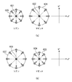
デバイスごと、色味ごとに変動量が異なるが、それに加えて変動量は指向性を持たない。変動する傾向をデバイス非依存の色空間のL*a*b*で示した場合、必ずしも同じ傾向で色味が変動するとは限らない。場合によっては、同じデバイスでキャリブレーション後の経過時間も同じであるのに、色再現性の変動傾向が全く正反対であるということも起こりうる。図6は、色味のずれを例示的に説明する図である。 Although the amount of variation differs for each device and color, the variation amount has no directivity. When the tendency to change is indicated by L * a * b * in a device-independent color space, the color does not necessarily change with the same tendency. In some cases, the same device may have the same elapsed time after calibration, but the variation tendency of color reproducibility may be completely opposite. FIG. 6 is a diagram for explaining the color shift by way of example.
図6(a)はハイエンドカラーMFPの色味のずれを例示する図であり、図6(b)はオフィスカラーMFPの色味のずれを例示する図である。ここではL*a*b*色空間のうち、a*b*平面を示している。中央の円601〜604がキャリブレーション実行時の画像形成の結果を示し、周囲の円605、606、607、608はキャリブレーション実行後、予め定められた時間経過時の画像形成の結果による色味のずれ(変動量)を模式的に示す。図6(a)、(b)に示すように、シアンとマゼンタの色の違いによって色再現性の変動量は相違する。また、図6(a)、(b)と比較するとわかるように同じシアン、マゼンタであっても色再現性の変動量は、ハイエンドMFPとオフィスカラーMFPとでは相違する。更に、キャリブレーション後の時間経過による色味のずれ(変動量)を示す円が中心から全方向に向いていることからわかるように、デバイスの色再現性の変動量は一般に指向性を持たない。
FIG. 6A is a diagram illustrating the color shift of the high-end color MFP, and FIG. 6B is a diagram illustrating the color shift of the office color MFP. Here, the a * b * plane is shown in the L * a * b * color space. The center circles 601 to 604 indicate the result of image formation at the time of calibration execution, and the surrounding
キャリブレーションを実行した後の変動量はデバイスの機種、CMYKの色味によって異なるため、キャリブレーション後の経過時間により一律にキャリブレーションを実行したとしても、効果的な補正をすることができない。 Since the amount of change after the calibration is performed differs depending on the device model and the color of CMYK, even if the calibration is performed uniformly according to the elapsed time after the calibration, effective correction cannot be performed.
(色再現性の定量化)
デバイスごとの色味のずれを定量的に評価し、画像データの出力先として複数のデバイスの優先順位づけを行う処理の流れを、図7、図8を参照して説明する。以下の説明では、リモートコピーの場合を例として説明する。図1に示す構成において、オフィスカラーMFP101をデータの送信側とすると、データの受信側としてハイエンドカラーMFP102、オフィスカラーMFP103、104のいずれかに対してリモートコピーを実行することが可能である。
(Quantification of color reproducibility)
A flow of processing for quantitatively evaluating the color shift for each device and prioritizing a plurality of devices as output destinations of image data will be described with reference to FIGS. In the following description, the case of remote copy will be described as an example. In the configuration shown in FIG. 1, if the
図7は、デバイスごとの色再現性の変動を定量的に評価し、出力するデータに適したデバイスの優先順位づけを行う処理の流れを説明するフローチャートである。本処理は、データ処理部205の全体的な制御の下に実行される。図7の処理において、スキャンを行うオフィスカラーMFP101がS701〜S706、S708〜S712の処理を実行する。一方、リモートコピーを実行する際のデータの受信側となるデバイスA、B、Cは、図1に示すハイエンドカラーMFP102、オフィスカラーMFP103、104に対応づけることが可能である。デバイスA、B、Cはそれぞれ記憶部202にキャリブレーション経過時間と、キャリブレーション経過時間を基準とした場合の色再現性の変動量(色味の変動量)を示すデバイス変動量LUTとを予め備える。そして、デバイスA、B、Cは、オフィスカラーMFP101からの要求に応じて、デバイス変動量LUTと、キャリブレーション経過時間に関する情報とをオフィスカラーMFP101に送信する(S707)。
FIG. 7 is a flowchart for explaining the flow of processing for quantitatively evaluating the variation in color reproducibility for each device and prioritizing devices suitable for output data. This process is executed under the overall control of the
図7に示すデバイスAは、デバイスAで実行されたキャリブレーション経過時間716と、キャリブレーション経過時間716を基準とした場合の色再現性の変動量を示すデバイス変動量LUT713と、を備えている。デバイスBは、デバイスBで実行されたキャリブレーション経過時間717と、キャリブレーション経過時間717を基準とした場合の色再現性の変動量を示すデバイス変動量LUT714と、を備えている。デバイスCは、デバイスCで実行されたキャリブレーション経過時間718と、キャリブレーション経過時間718を基準とした場合の色再現性の変動量を示すデバイス変動量LUT715と、を備えている。
The device A shown in FIG. 7 includes a calibration elapsed
(デバイス変動量LUTの説明)
ここで、図7のフローチャートの各処理を説明する前に、デバイス変動量LUTについて図8を用いて説明する。デバイス変動量LUTは、3次元ルックアップテーブル(3D−LUT)の形式を備える。通常の3D-LUTは特定の色空間を別の色空間に変換するために用いられるが、本実施形態では、ある一定の経過時間における色味の変動量(変動範囲)を示す。例えば、デバイス変動量LUT801(図8)は、直近に実行したキャリブレーションからの経過時間(基準時間)として5日経過した状態の色味の変動量を例示している。RGB=(0、0、17)を入力データとすると、色味の変動量として、L*は±10の範囲で変動し、b*は±20の範囲で変動し、A*は変動していないことを示している。このデバイス変動量LUTは各デバイスによって値が異なる。
(Explanation of device variation LUT)
Here, before explaining each process of the flowchart of FIG. 7, the device variation amount LUT will be described with reference to FIG. 8. The device variation amount LUT has a three-dimensional lookup table (3D-LUT) format. A normal 3D-LUT is used to convert a specific color space to another color space. In the present embodiment, the amount of color variation (variation range) at a certain elapsed time is indicated. For example, the device variation amount LUT 801 (FIG. 8) illustrates the variation amount of the color after five days have passed as the elapsed time (reference time) from the most recently executed calibration. Assuming that RGB = (0, 0, 17) is input data, as the amount of color variation, L * varies within a range of ± 10, b * varies within a range of ± 20, and A * varies. It shows no. The device variation amount LUT has a different value for each device.
(デバイス変動量LUTの生成方法)
次に、デバイス変動量LUTの生成方法について説明する。まず、デバイス変動量LUTを生成するためのRGBデータを用意する。このRGBデータは、例えば、図3のS304で求めた共通RGBデータを利用することが可能である。このRGBデータが、デバイス変動量LUT801の入力側の3次元情報となる。
(Method for generating device variation LUT)
Next, a method for generating the device variation amount LUT will be described. First, RGB data for generating a device variation LUT is prepared. As the RGB data, for example, the common RGB data obtained in S304 of FIG. 3 can be used. This RGB data becomes the three-dimensional information on the input side of the
次に、このRGBデータを図3のS308における色変換処理2(第2色変換処理)でCMYK(多値)データに変換して出力する。この出力結果に基づき測色機を用いてデバイスに非依存の色空間におけるL*a*b*を測定する(第1測定結果)。この第1測定結果は、直近に実行されたキャリブレーション直後の測定結果に対応するものであり、時間経過により色味の変動が生じていないデータとなる。 Next, this RGB data is converted into CMYK (multi-value) data by color conversion processing 2 (second color conversion processing) in S308 of FIG. 3 and output. Based on the output result, a colorimeter is used to measure L * a * b * in a device-independent color space (first measurement result). This first measurement result corresponds to the measurement result immediately after the calibration executed most recently, and is data in which the color does not vary over time.
その後、キャリブレーションを行わない状態で予め定めた期間(基準時間)デバイスを稼動させ、同様のデータをデバイスから出力させる。そして、この出力結果に基づき測色機を用いてデバイスに非依存の色空間におけるL*a*b*を測定する(第2測定結果)。 Thereafter, the device is operated for a predetermined period (reference time) in a state where calibration is not performed, and similar data is output from the device. Based on this output result, L * a * b * in a color space independent of the device is measured using a colorimeter (second measurement result).
次に2つの測定結果から差分の絶対値(|(第1測定結果)―(第2測定結果)|)を計算する。この差分の絶対値が、直近に実行したキャリブレーションからの経過時間(基準時間)における色味の変動量となる。データ処理部205は、この値をデバイス変動量LUTの出力側に格納する。ここでデバイス変動量LUTの出力側をデバイスに非依存の色空間L*a*b*の測定結果としたが、例えば、XYZ、CMY、L*u*v*等の色空間であってもよい。また、同様の処理を複数のデバイスで行い、平均値または最大値を取ってデバイス変動量LUTを生成することにより精度の高いデバイス変動量LUTを生成することも可能である。
Next, the absolute value of the difference (| (first measurement result) − (second measurement result) |) is calculated from the two measurement results. The absolute value of this difference is the amount of color variation in the elapsed time (reference time) since the most recently executed calibration. The
説明を図7に戻し、具体的な処理の流れを説明する。まず、ステップS702において、データ処理部205は、画像読み取り部201を制御して、原稿701を読み込み、データを取得する。
Returning to FIG. 7, the specific processing flow will be described. First, in step S702, the
次に、ステップS703において、データ処理部205は、スキャナ画像処理を実行する。これは図3のS301〜S304の処理と同様の処理である。
Next, in step S703, the
次にステップS704において、データ処理部205は、像域分離処理を行う。データ処理部205は画像データのエッジ部分を抽出し、画像データの各画素が文字か写真かを判定する。
In step S704, the
そして、ステップS705で、データ処理部205は、文字でない画素のRGB値をカウントし、その中で出現頻度の高いRGB値を抽出する。データ処理部205は、出現頻度の高いRGB値を記憶部202に格納する(S706)。ここでRGB値のカウント方法は、階調が8bit(0〜255)である場合、例えば、全ての階調数分をカウントして出現頻度の高いRGB値を抽出することが可能である。この場合、全ての階調数分をカウントせず、特定の範囲内に入っているデータを1つのデータとしてカウントすることも可能である。例えば、0〜255を32刻みでカウントし、その範囲内にあるデータを1つのデータとして扱えば、データの量を削減することが可能となる。本実施形態では像域分離処理を行って文字でない画素のRGB値をカウントし、その中で出現頻度の高いRGB値を抽出しているが、これは文字よりも写真のデータの方が色再現をより重視すると判断しているためである。写真のデータの色再現を重視しない場合は、像域分離処理を用いた切り分けは行わなくてもよい。
In step S705, the
S708において、データ処理部205は、ネットワーク106に接続するデバイスA、デバイスB、デバイスCに対して、各デバイスが有するデバイス変動量LUTとキャリブレーション経過時間に関する情報を要求する。そして、データ処理部205は、この要求に基づき各デバイスから送信(S707)されたデバイス変動量LUT713、714、715とキャリブレーション経過時間716、717、718を受信する。データ処理部205は、受信したデバイス変動量LUT713、714、715と、キャリブレーション経過時間716、717、718とに基づき、新しいデバイス変動量LUTを生成する。新しいデバイス変動量LUTは、キャリブレーション経過時間(基準時間)と、キャリブレーション実行時から現在時刻までの経過時間と、の比率により色再現性の変動量を補間するデータとして生成される。データ処理部205は、この補間結果に基づき、出力すべき画像データに対する画質の変動量を算出することができる。
In step S <b> 708, the
図9は、ステップS708の具体的な処理の流れを説明する図である。本処理は、データ処理部205の全体的な制御の下に実行される。ここでは説明を簡明にするため、データの受信側となるデバイスをデバイスA、1台として説明している。
FIG. 9 is a diagram illustrating a specific processing flow of step S708. This process is executed under the overall control of the
まず、ステップS901で、データ処理部205は、デバイスAから送信されるキャリブレーション経過時間716を受信する。
First, in step S <b> 901, the
次に、ステップS902で、データ処理部205は、デバイスAから送信されたデバイス変動量LUT713を受信する。
Next, in step S902, the
そして、ステップS903において、データ処理部205は、年月日時刻の計測が可能な不図示のタイマーにより計測されている現在時刻の情報により、キャリブレーションの実行から現在時刻までの経過時間を求める。
In step S903, the
ステップS904において、データ処理部205は、新しいデバイス変動量LUTを算出する。データ処理部205は、(1)式に基づき新しいデバイス変動量LUTを算出することが可能である。
In step S904, the
新しいデバイス変動量LUT
=デバイス変動量LUT×経過時間/基準時間 ・・・(1)
経過時間が基準時間と一致する場合、新しいデバイス変動量LUTは予め生成されているデバイス変動量LUTと一致する。図10はキャリブレーションから3日経過後(経過時間3日)の新しいデバイス変動量LUTを例示する図である。新しいデバイス変動量LUT1001の出力側のデータは、図8で説明したデバイス変動量LUT801の出力側のデータ(基準時間5日)を3/5倍した補間データとなる。
New device variation LUT
= Device fluctuation amount LUT x elapsed time / reference time (1)
When the elapsed time matches the reference time, the new device fluctuation amount LUT matches the device fluctuation amount LUT generated in advance. FIG. 10 is a diagram illustrating a new device fluctuation amount LUT after 3 days from calibration (elapsed
以上の処理により新しいデバイス変動量LUTを生成する処理(S708、図9)を終了する。説明を図7に戻し、ステップS709で、データ処理部205は、S708で生成された新しいデバイス変動量LUT(以下、「新デバイス変動量LUT」ともいう)を記憶部202に格納する。デバイスが複数ある場合は、複数のデバイスそれぞれについて、新デバイス変動量LUTが生成され、記憶部202に格納される。
The process (S708, FIG. 9) for generating a new device fluctuation amount LUT is completed by the above process. Returning to FIG. 7, in step S <b> 709, the
ステップS710で、データ処理部205は、記憶部202に格納された出現頻度の高いRGB値(S706)と、新デバイス変動量LUT(S709)と、を読み出す。そして、データ処理部205は、新デバイス変動量LUT(S709)を用いて出現頻度の高いRGB値(S706)を、色再現性の変動量を示すデータ(L*a*b*)に変換する。この変換処理により、データ処理部205は、新デバイス変動量LUTに基づき、出力すべき画像データに対する画質の変動量を複数のデバイスそれぞれに対して算出することができる。
In step S710, the
ステップS711において、データ処理部205は、変換処理の結果により得られたL*、a*、b*値に基づき、色再現性の変動量の大小を評価するための評価パラメータを算出する。そして、データ処理部205は、評価パラメータを順次加算してき、評価パラメータの総和を求める。
In step S711, the
評価パラメータの総和の算出には、例えば、色の出現頻度に応じて重みを設定することが可能である。L*、a*、b*に基づく評価パラメータの総和の算出については、図22の参照により後に詳細に説明する。データ処理部205は、ここで算出された評価パラメータの総和(加算結果)を各デバイスの新デバイス変動量LUTについて同様に求める。この総和が小さいデバイスが読み込んだ原稿701に対して最も変動量が少ないデバイスとなる。
For the calculation of the sum of evaluation parameters, for example, a weight can be set according to the appearance frequency of colors. The calculation of the sum of evaluation parameters based on L *, a *, and b * will be described in detail later with reference to FIG. The
S712において、表示部204は、データ処理部205の表示制御の下、L*、a*、b*の値に基づく評価パラメータの総和(加算結果)の小さい順にユーザインタフェース(UI)にデバイス名を表示し、処理を終了する。
In step S712, the
(評価パラメータの算出処理(S710〜S712))
次に、図7で説明したS710〜S712の処理の具体的な処理を、図22の参照により説明する。本処理はデータ処理部205の全体的な制御下に実行される。
(Evaluation parameter calculation processing (S710 to S712))
Next, specific processing of S710 to S712 described in FIG. 7 will be described with reference to FIG. This process is executed under the overall control of the
ステップS2201において、データ処理部205は、記憶部202に格納されている、新デバイス変動量LUT(S709)を1つ読み出す。例えば、ネットワーク106に接続されているデバイスA、B、Cに対応する新デバイス変動量LUT―A、B、Cが記憶部202に格納されている場合、これらのLUTが1つ選択され読み出される。
In step S2201, the
次にステップS2202において、データ処理部205は、記憶部202に格納されているRGB値(S706)を読み出す。
Next, in step S2202, the
そしてステップS2203において、データ処理部205は、RGB値(S706)に対して、読み出された新デバイス変動量LUTを用いてRGB値の変換処理を行う。新デバイス変動量LUTは、3D−LUTの形式を有しており、入力のRGB値に対して、RGB値の変動量としてL*、a*、b*値が出力される。
In step S2203, the
ステップS2204において、データ処理部205は、変換処理の結果により得られたL*、a*、b*値に基づき、以下に(2)式により色再現性の変動量の大小を評価するための評価パラメータを算出する。そして、データ処理部205は、各RGB値に対して算出された評価パラメータを順次加算してき、加算された評価パラメータの総和(加算結果)を記憶部202に格納する(S2205)。データ処理部205は、評価パラメータの総和(加算結果)とともに、演算に用いた新デバイス変動量LUTがどのデバイスに対応するかを、対応付けて記憶部202に格納する。これにより、評価パラメータの総和(加算結果)とデバイスとを対応付けることができる。
In step S2204, the

ステップS2206において、データ処理部205は、全てのRGB値に対して計算が終了したか判定する。全てのRGB値に対して計算が終了していない場合(S2206−No)、ステップS2202に戻り、同様の処理が繰り返される。一方、全てのRGB値に対して計算が終了した場合(S2206−Yes)、処理はステップS2207に進められる。
In step S2206, the
ステップS2207において、データ処理部205は、全ての新デバイス変動量LUTについて計算が終了したか判定し、終了していない場合(S2207−No)、ステップS2201に戻り、同様の処理が繰り返される。S2201において、データ処理部205は、次の新デバイス変動量LUTを選択し、読み出す。データ処理部205は、ステップS2202で読み出したRGB値に対して、新たに読み出した新デバイス変動量LUTを用いて変換処理を行う。データ処理部205は、変換処理の結果により得られたL*、a*、b*値に基づき評価パラメータを算出し、評価パラメータを順次加算してき、評価パラメータの総和を記憶部202に格納する(S2205)。記憶部202には、新デバイス変動量LUTそれぞれに基づいて算出された評価パラメータの総和が格納される。
In step S2207, the
全てのRGBデータに対する計算が終了し(S2206−Yes)、全ての新デバイス変動量LUTについて計算が終了すると(S2207−Yes)、処理はS2208に進められる。 When calculation for all RGB data is completed (S2206-Yes) and calculation is completed for all new device variation LUTs (S2207-Yes), the process proceeds to S2208.
ステップS2208において、データ処理部205は、記憶部202から新デバイス変動量LUTそれぞれに基づいて算出された評価パラメータの総和(加算結果)を比較する。データ処理部205は、評価パラメータの総和(加算結果)の大小関係を判定する。
In step S2208, the
そして、S2208の判定結果に基づき、表示部204はデータ処理部205の表示制御の下、評価パラメータの総和の小さい順に、対応するデバイス名をユーザインタフェース(UI)に表示する(S712)。
Based on the determination result of S2208, the
本実施形態に拠れば、原稿中にある出現頻度の高い特定の色に対するデバイスごとの変動量を定量的に評価することが可能になる。 According to the present embodiment, it is possible to quantitatively evaluate the amount of change for each device with respect to a specific color having a high appearance frequency in a document.
本実施形態では算出された評価パラメータを一律に加算しているが、例えば、RGBの出現頻度に応じた重み付け係数を評価パラメータに乗じることで出現頻度の情報を評価パラメータの総和(加算結果)に反映することも可能である。 In this embodiment, the calculated evaluation parameters are uniformly added. For example, by multiplying the evaluation parameters by a weighting coefficient corresponding to the appearance frequencies of RGB, the appearance frequency information is added to the sum of the evaluation parameters (addition result). It can also be reflected.
ユーザは、S712の処理によりUIに表示されたデバイス名を参照して、変動量の最も小さいデバイスを選択することが可能である。UI上に表示されたデバイスの中からユーザがデバイスを選択すると、データ処理部205の制御の下、選択されたデバイスに対してデータが送信される。
The user can select the device with the smallest amount of fluctuation with reference to the device name displayed on the UI in the process of S712. When the user selects a device from the devices displayed on the UI, data is transmitted to the selected device under the control of the
データを受信したデバイスは通常のリモートコピーの処理と同じようにプリンタ画像処理(図3のS308〜S313)を実行する。ここで、デバイスをリスト表示せず、最も評価パラメータの総和(加算結果)の小さいデバイスに対して、データ処理部205がデータを自動送信することも可能である。
The device that has received the data executes printer image processing (S308 to S313 in FIG. 3) in the same manner as normal remote copy processing. Here, it is also possible for the
(UI画面表示例)
図11は、リモートコピーを実行する際のUI画面1101を例示的に示す図である。リモートコピーが可能なデバイスをユーザが選択する際に、UI画面には、色再現性レベルが表示される。色再現性レベルは、評価パラメータの総和(加算結果)に対する閾値処理により、高い≦(第1閾値)、第1閾値<普通≦第2閾値、第2閾値<低い、の3つのレベルに分けて表示される。
(Example of UI screen display)
FIG. 11 is a diagram exemplarily showing a
ここで、「高い」デバイスは、リモートコピー処理において、色再現性レベルが最も高いデバイスを示し、「普通」のデバイス、「低い」デバイスの順に、リモートコピー処理における色再現性レベルは低くなる。 Here, the “high” device indicates a device having the highest color reproducibility level in the remote copy process, and the color reproducibility level in the remote copy process decreases in the order of “normal” device and “low” device.
図11に示すUI画面1101において、色再現性レベルの順位はデバイスB、デバイスC、デバイスAの順となり、デバイスBがリモートコピー処理に適した優先順位の高いデバイスとして表示される。
In the
本実施形態ではフルカラーの原稿を対象にしているが、原稿はモノクロや2色のものであってもよい。モノクロのみを対象とする場合、例えば、図21の参照番号2101のように単色のデバイス変動量LUTを使用することも可能である。その場合に必要となるLUTは1次元ルックアップテーブルの形式となり、出力も輝度値(輝度の情報の変動量)のみで良くなるため、記憶部202の記憶容量の削減が可能になる。
In this embodiment, a full-color original is targeted, but the original may be monochrome or two-color. When only monochrome is targeted, for example, a monochrome device variation LUT can be used as indicated by
(1)式の場合、キャリブレーション経過時間を基準に、新デバイス変動量LUTを算出しているが、本発明の趣旨は、この例に限定されるものではない。例えば、デバイス変動量LUTを生成する際に基準とした印刷枚数(基準枚数)と、キャリブレーション後に印刷出力した印刷用紙の枚数とに基づき、新デバイス変動量LUTを(3)式の関係により算出することができる。 In the case of equation (1), the new device fluctuation amount LUT is calculated based on the calibration elapsed time, but the gist of the present invention is not limited to this example. For example, based on the number of printed sheets (reference number) used as a reference when generating the device fluctuation amount LUT and the number of print sheets printed and output after calibration, the new device fluctuation amount LUT is calculated by the relationship of the expression (3). can do.
新しいデバイス変動量LUT
=デバイス変動量LUT×キャリブレーション後に印刷出力した印刷用紙枚数/基準枚数 ・・・(3)
その他にも、デバイス変動量LUTを生成する際に基準としたデバイスの設置場所の温度(基準温度)と、デバイス使用時の温度との関係に基づいて、(4)式より新デバイス変動量LUTを算出することもできる。
New device variation LUT
= Device variation amount LUT × Number of printed sheets printed after calibration / reference number (3)
In addition, based on the relationship between the temperature at which the device is installed (reference temperature) and the temperature when the device is used as a reference when generating the device fluctuation amount LUT, the new device fluctuation amount LUT is calculated from the equation (4). Can also be calculated.
新しいデバイス変動量LUT
=デバイス変動量LUTデバイス使用時の温度/基準温度・・・(4)
また、本実施形態ではデータを受信する受信側の各デバイスがデバイス変動量LUTを備える構成を説明しているが、データの送信側のデバイスが受信側の各デバイスのデバイス変動量LUTを備える構成でもよい。この場合、データの送信側のデバイスは、受信側の各デバイスからキャリブレーション経過時間716、717、718を受信すればよい。
New device variation LUT
= Device variation amount Temperature / reference temperature when using LUT device (4)
Further, in the present embodiment, a configuration is described in which each device on the reception side that receives data includes a device variation LUT, but a configuration in which a device on the data transmission side includes a device variation LUT of each device on the reception side. But you can. In this case, the device on the data transmission side may receive the calibration elapsed
また、デバイスの変動量として本実施形態では「色味」に着目しているが、例えば、RGB値に対応したプリンタの色ずれの変動量をLUT化して、変動量を定量化することも可能である。 In this embodiment, “color” is focused on as the amount of device variation. For example, the amount of variation in printer color misregistration corresponding to RGB values can be converted into LUTs to quantify the amount of variation. It is.
本実施形態に拠れば、原稿のRGB値の出現頻度に応じて色再現性の変動量の少ないデバイスを選択することが可能になる。 According to the present embodiment, it is possible to select a device with a small amount of variation in color reproducibility according to the appearance frequency of the RGB values of the document.
(第2実施形態)
次に、デバイスが持つ色再現範囲を考慮した実施形態について説明する。第1実施形態では、リモートコピーの際に色再現性レベルの変動量の小さいデバイスを選択可能にする構成を説明したが、本実施形態ではさらに選択可能なデバイスの色再現範囲を考慮する構成について説明する。
(Second Embodiment)
Next, an embodiment that considers the color reproduction range of the device will be described. In the first embodiment, a configuration has been described in which a device with a small amount of variation in color reproducibility level can be selected during remote copying. However, in this embodiment, a configuration that further considers the color reproduction range of a selectable device. explain.
第1実施形態では、各デバイスにおける色再現性の変動量に着目したが、実際にはデバイスごとに異なる色再現範囲を持つ。一般にハイエンドデバイスであるほど色再現範囲が広く、オフィス用デバイスは色再現範囲が狭い。そのため、ハイエンドデバイスでは再現できていた色がオフィス用デバイスになると再現できなくなるという現象が起こる。そのような場合、再現不可能なオフィス用デバイスで出力するよりは、色味が変動していても再現可能なハイエンドデバイスで出力した方がユーザにとって望ましい。そこで本実施形態ではRGB値の抽出処理において特定のデバイスでのみ再現可能な色が抽出された場合の処理の流れを説明する。 In the first embodiment, attention is paid to the amount of variation in color reproducibility in each device, but actually, each device has a different color reproduction range. In general, the higher the end device, the wider the color reproduction range, and the office device has a smaller color reproduction range. For this reason, a phenomenon occurs in which a color that can be reproduced on a high-end device cannot be reproduced if it becomes an office device. In such a case, it is more desirable for the user to output with a high-end device that can be reproduced even if the color changes, rather than with an office device that cannot be reproduced. Therefore, in the present embodiment, the flow of processing when a color that can be reproduced only by a specific device is extracted in the RGB value extraction processing will be described.
図14は、第2実施形態における処理の流れを説明する図である。 FIG. 14 is a diagram for explaining the flow of processing in the second embodiment.
ステップS1412とステップS1413以外は図7のフローチャートと同様の処理であり、説明の重複を避けるため図7と同様の処理ステップについては説明を省略する。 Processes other than step S1412 and step S1413 are the same as those in the flowchart of FIG. 7, and the description of the same process steps as in FIG.
ここでは、S705のRGB値を抽出する処理でハイエンドデバイスでのみ再現可能な色(RGB=(255,255、0))が抽出された場合を説明する。 Here, a case where a color (RGB = (255, 255, 0)) that can be reproduced only by a high-end device is extracted in the process of extracting RGB values in S705 will be described.
S708の新デバイス変動量LUTの生成処理において(S708)、データ処理部205は、色再現範囲を超えるデータに対しては、異常状態を評価パラメータの算出結果に反映するために、極端に大きい変換値を設定する。
In the new device fluctuation amount LUT generation processing of S708 (S708), the
図12は、ハイエンドデバイス(ハイエンドカラーMFP)、オフィス用デバイス(オフィスカラーMFP)が備えるデバイス変動量LUTを例示する図である。図12において、参照番号1201はハイエンドカラーMFPを対象としたデバイス変動量LUTであり、参照番号1202はオフィスカラーMFPを対象としたデバイス変動量LUTである。ここでRGB=(0、0、0)から(204,255、0)の範囲で表示されているRGB値は、ハイエンドカラーMFPでも、オフィスカラーMFPでも、共に色再現範囲内に入っているデータである。
FIG. 12 is a diagram illustrating device variation LUTs included in a high-end device (high-end color MFP) and an office device (office color MFP). In FIG. 12,
また、RGB=(255,255、0)で表現される色は、ハイエンドカラーMFPの色再現範囲内にあるデータであるが、オフィスカラーMFPの色再現範囲を超えるデータである。ハイエンドカラーMFP用のデバイス変動量LUT1201の出力として、RGB=(255,255、0)で表現される色は、デバイス変動量LUT1201によりL*a*b*=(10、0、20)と変換される。一方、RGB=(255,255、0)で表現される色は、オフィスカラーMFP用のデバイス変動量LUT1202の出力として、L*a*b*=(100、256、256)と極端に大きい数値に変換される。
The color expressed by RGB = (255, 255, 0) is data that is within the color reproduction range of the high-end color MFP, but is data that exceeds the color reproduction range of the office color MFP. As an output of the
変換されたL*、a*、b*の値に基づき、データ処理部205は、変動量を評価する評価パラメータを算出し、評価パラメータの総和を求める(S711)。色再現範囲を超えるオフィスカラーMFPにおける評価パラメータの総和は、ハイエンドカラーMFPにおける評価パラメータの総和に比べて大きくなる。そのため、オフィスカラーMFPの優先順位は、ハイエンドカラーMFPより低くなる。
Based on the converted values of L *, a *, and b *, the
ステップS1412において、データ処理部205は、入力されたRGB値が色再現範囲内にあるか否かの判定を行う。ここでは、特定の閾値を設けて閾値以下であった場合に、データ処理部205は色再現範囲内のデータと判定し、閾値よりも大きい場合に色再現範囲を超えるデータと判定する。
In step S1412, the
ステップS1413において、表示部204は、データ処理部205の表示制御の下、評価パラメータの総和の小さい順に、対応するデバイス名をユーザインタフェース(UI)に表示する。色再現範囲を超えるデバイスに関しては、大きい変換値に基づき評価パラメータが算出される。そのため、評価パラメータの総和を比較した場合、オフィスカラーMFPの優先順位は、ハイエンドカラーMFPに比べて低くなる。
In step S1413, the
更に、表示部204は、データ処理部205の表示制御の下、色再現可能性の判定結果(S1412)を、色再現性レベルに基づく優先順位の表示と組み合わせてUIに表示する。
Further, under the display control of the
図13は、S1413の処理により表示されるUI画面1301を例示的に示す図である。ここでは入力された原稿に対してデバイスB(ハイエンドカラーMFP)のみ色再現が可能であることを示している。デバイスA、C(オフィスカラーMFP)のデバイス変動量LUTは入力された原稿のRGB値に対して極端に大きい値が設定されているため、優先順位はデバイスBより下がる。また、デバイスA、C(オフィスカラーMFP)は、色再現が不可能であることを示している。
FIG. 13 is a diagram exemplarily showing a
本実施形態に拠れば、色再現範囲の異なるデバイスが混在する場合でも、原稿のRGB値の再現が可能なデバイスを選択することが可能になる。 According to the present embodiment, even when devices having different color reproduction ranges coexist, it is possible to select a device that can reproduce the RGB values of the document.
(第3実施形態)
第1実施形態では、リモートコピーの際に色再現性レベルの変動量の小さいデバイスを選択可能にする構成を説明しが、本実施形態では評価パラメータの総和が同一となる場合に、デバイスの情報を用いてソートを行う例を説明する。
(Third embodiment)
In the first embodiment, a configuration is described in which a device with a small amount of variation in color reproducibility level can be selected during remote copying. However, in this embodiment, when the sum of evaluation parameters is the same, device information An example in which sorting is performed using will be described.
図15は、第3実施形態における処理の流れを説明する図である。ステップS1522〜ステップS1524以外は図7のフローチャートと同様の処理であり、説明の重複を避けるため図7と同様の処理ステップについては説明を省略する。 FIG. 15 is a diagram for explaining the flow of processing in the third embodiment. Except for steps S1522 to S1524, the processing is the same as that of the flowchart of FIG. 7, and the description of the processing steps similar to those of FIG.
デバイスA、B、Cは、デバイス変動量LUT713〜715、キャリブレーション経過時間716〜718の他に、デバイス情報1519〜1521を備える。S707において、デバイスA、B、Cは、オフィスカラーMFP101からの要求に応じて、デバイス変動量LUTと、キャリブレーションの時刻に関する情報とをオフィスカラーMFP101に送信する。この際、デバイス情報1519〜1521も合わせてオフィスカラーMFP101に送信される。デバイス情報は、デバイスの性能を評価するための情報である。例えば、印刷速度に関して、1分間の出力枚数をデバイス情報とすることができる。また、印刷の解像度など、印刷品位に関する情報をデバイス情報とすることも可能である。
The devices A, B, and C include
ステップS711において、評価パラメータの総和が算出された後、ステップS1522において、データ処理部205は、デバイスA、B、Cの中で評価パラメータの総和が同一となるデータがあるか判定する。S1522の判定により、評価パラメータの総和が同一となるデータが無い場合(S1522−No)、処理はステップS712に進められる。S712において、表示部204は、データ処理部205の表示制御の下、L*、a*、b*の値に基づく評価パラメータの総和(加算結果)の小さい順にユーザインタフェース(UI)にデバイス名を表示し、処理を終了する。
In step S711, after the sum of evaluation parameters is calculated, in step S1522, the
一方、S1522の判定で、評価パラメータの総和が同一となるデータが存在する場合(S1522−Yes)、処理はS1523に進められる。S1523において、データ処理部205は、評価パラメータの総和が同一となるデバイスを特定する。データ処理部205は、新デバイス変動量LUTと対応付けられているデバイス名称によりデバイスを特定することができる。そして、データ処理部205は、特定されたデバイスに対応するデバイス情報を比較して、デバイスの優先順位を決定する。データ処理部205は、デバイスの性能を示すデバイス情報に基づいて、評価パラメータの総和が同一となるデバイスの優先順位を決定する。データ処理部205は、例えば、デバイス情報が「1分間の出力枚数」(印刷速度)である場合は、単位時間当たりの出力枚数の多い順に優先順位を決定する。また、デバイス情報が「印刷の解像度」(印刷品位)である場合は、解像度の高い順に優先順位を決定する。
On the other hand, if it is determined in S1522 that there is data having the same sum of the evaluation parameters (S1522-Yes), the process proceeds to S1523. In step S1523, the
そして、S1524において、表示部204は、データ処理部205の表示制御の下、S1523で決定された優先順位に従い、優先順位の高い順に、対応するデバイス名をユーザインタフェース(UI)に表示する。
In step S1524, the
図16は、S1524の処理により表示されるUI画面1601を例示的に示す図である。デバイスA、B、Cは、データの受信側となるデバイスであり、この中で、デバイスBとデバイスCは、評価パラメータの総和が同一となる。データの送信側となるデバイスのデータ処理部205は、デバイスB、Cから送信されたデバイス情報を比較して、デバイスの優先順位を決定する。ここでデバイスBの出力枚数は単位時間(1分)当たり70枚であり、デバイスCの出力枚数は単位時間(1分)当たり30枚であり、単位時間当たりの出力枚数の多いデバイスBの優先順位をデバイスCの優先順位より高くする。デバイスAに関しては、評価パラメータの総和がデバイスB、Cに比べて大きいため、最も低い優先順位のデバイスとして決定される。デバイスAに関しても、UI画面1601では、評価パラメータの総和と共に単位時間あたりの出力枚数に関するデバイス情報が組み合わせて表示される。
FIG. 16 is a diagram exemplarily showing a
本実施形態では、デバイス情報をデータの受信側のデバイスA、B、Cが備える構成としたが、この構成に限定されず、例えば、データの送信側のデバイスがデバイス情報を備える構成とすることも可能である。 In this embodiment, the device information is provided in the devices A, B, and C on the data receiving side. However, the present invention is not limited to this configuration. For example, the device on the data transmitting side is provided with the device information. Is also possible.
本実施形態に拠れば、色再現性のレベルが同一となるデバイスに関しては、デバイスの性能を示すデバイス情報に基づき選択の対象となるデバイスの優先順位を決定することが可能になる。 According to this embodiment, with respect to devices having the same color reproducibility level, it is possible to determine the priority order of devices to be selected based on device information indicating device performance.
(第4実施形態)
第1実施形態では、リモートコピーの際に色再現性レベルの変動量の小さいデバイスを選択可能にする構成を説明しが、本実施形態ではドライバ出力の適用例について説明する。
(Fourth embodiment)
In the first embodiment, a configuration is described in which a device with a small variation in color reproducibility level can be selected during remote copying. In this embodiment, an example of application of driver output will be described.
図17は、第4実施形態における処理の流れを説明する図である。第1実施形態では、データの送信側となるデバイス(例えば、図1のオフィスカラーMFP101)が図7のS701〜S706、S708〜S712の処理を行っていた。本実施形態では対応する処理を情報処理装置(PC)が実行する。本処理は、PCのCPU(不図示)がデータ処理を実行するデータ処理手段として機能する。
FIG. 17 is a diagram for explaining the flow of processing in the fourth embodiment. In the first embodiment, the device (for example, the
まず、ステップS1702において、アプリケーション等により生成された画像データ1701を読み込む。原稿の場合と違い、1つのデータで複数のページが存在する可能性がある。複数のページが存在する場合は各ページ単位に同様の処理を実行することにより本処理を適用することが可能である。
First, in step S1702,
次にステップS1703において、CPUの制御の下、読み込んだ画像データに対してドライバ画像処理が実行される。ドライバ画像処理は、図3のS315〜S318に対応する処理である。その後アプリケーションから得られる情報を用いて、ステップS1704にて文字と写真のデータとを分離する像域分離処理を行う。 In step S1703, driver image processing is executed on the read image data under the control of the CPU. The driver image processing is processing corresponding to S315 to S318 in FIG. Thereafter, using the information obtained from the application, an image area separation process for separating character data and photo data is performed in step S1704.
次に、ステップS1705において、CPUは、文字でない画素のRGB値をカウントし、その中で出現頻度の高いRGB値を抽出する。CPUは、出現頻度の高いRGB値を記憶部202に格納する(S1706)。 Next, in step S1705, the CPU counts the RGB values of pixels that are not characters, and extracts the RGB values having a high appearance frequency among them. The CPU stores the RGB values having a high appearance frequency in the storage unit 202 (S1706).
S1708において、CPUは、ネットワーク106に接続するデバイスA、デバイスB、デバイスCに対して、各デバイスが有するデバイス変動量LUTとキャリブレーション経過時間に関する情報を要求する。そして、CPUは、この要求に基づき各デバイスから送信(S1707)されたデバイス変動量LUT713、714、715とキャリブレーション経過時間716、717、718を受信する。CPUは、受信したデバイス変動量LUT713、714、715と、キャリブレーション経過時間716、717、718とに基づき、新しいデバイス変動量LUTを生成する。
In step S <b> 1708, the CPU requests devices A, B, and C connected to the
ステップS1709で、CPUは、S1708で生成された新デバイス変動量LUTを記憶部202に格納する。
In step S1709, the CPU stores the new device fluctuation amount LUT generated in step S1708 in the
ステップS1710で、CPUは、RGB値(S1706)と、新デバイス変動量LUTと、を読み出す。そして、CPUは、新デバイス変動量LUTを用いて出現頻度の高いRGB値を、色再現性の変動量を示すデータ(L*a*b*)に変換する。 In step S1710, the CPU reads the RGB value (S1706) and the new device fluctuation amount LUT. Then, the CPU converts the RGB value having a high appearance frequency into data (L * a * b *) indicating the variation amount of color reproducibility using the new device variation amount LUT.
ステップS1711において、CPUは、変換処理の結果により得られたL*、a*、b*値に基づき、色再現性の変動量の大小を評価するための評価パラメータを算出する。そして、CPUは、評価パラメータを順次加算してき、評価パラメータの総和を求める。 In step S1711, the CPU calculates an evaluation parameter for evaluating the amount of variation in color reproducibility based on the L *, a *, and b * values obtained as a result of the conversion process. Then, the CPU sequentially adds the evaluation parameters to obtain the sum of the evaluation parameters.
S1712において、情報処理装置(PC)の表示部は、CPUの表示制御の下、L*、a*、b*の値に基づく評価パラメータの総和の小さい順にUI画面にデバイス名を表示し、処理を終了する。このUI画面は、例えば第1実施形態で説明したUI画面である。 In S1712, the display unit of the information processing device (PC) displays device names on the UI screen in ascending order of the sum of the evaluation parameters based on the values of L *, a *, and b * under the display control of the CPU. Exit. This UI screen is, for example, the UI screen described in the first embodiment.
本実施形態に拠れば、ユーザがPCからのドライバ出力を行う際に、画像データのRGB値の出現頻度に応じて色再現性の変動量の少ないデバイスを選択することが可能になる。 According to this embodiment, when a user performs driver output from a PC, it is possible to select a device with a small amount of variation in color reproducibility according to the appearance frequency of RGB values of image data.
(第5実施形態)
第1乃至第4実施形態では、原稿または画像データのRGBデータから出現頻度の高いものを抽出して処理を行う例を説明した。本実施形態では特定の色の再現性を強調するために、ユーザが指定した色に関する情報に基づいて、ユーザの指定に適したデバイスを選択可能にする構成を説明する。
(Fifth embodiment)
In the first to fourth embodiments, an example has been described in which processing is performed by extracting a document or image data having a high appearance frequency from RGB data. In this embodiment, in order to emphasize the reproducibility of a specific color, a configuration that enables selection of a device suitable for the user's designation based on information on the color designated by the user will be described.
図18は、スキャンを実行する前に、特定の色の再現性を強調するために、特定の色の指定を受け付けるためのUI画面1801を例示する図である。UI画面1801では、赤、緑、青、シアン、マゼンタ、イエロー、ブラックの各色に対してそれぞれ薄い色、濃い色に分け、これらの色に対してユーザが再現を重視する色を指定できるようになっている。UI画面1801では薄い緑、薄い青、薄いシアンにチェックがつけられており、これらの色が再現性を強調するために指定されている色となる。ユーザの指定が終了して、実行ボタン1802が押下されるとユーザの指定が確定し、スキャナ画像処理が実行される。ここで、スキャナ画像処理は、図3のS301〜S304に対応する処理である。スキャナ画像処理が行われた後、図19に示すフローに従って処理が実行される。本処理は、データ処理部205の制御の下に実行される。図19のフローチャートにおいて、図7のフローチャートと同様の処理については同一のステップ番号を付して、詳細な説明については、説明を簡略化する。
FIG. 18 is a diagram exemplifying a
まず、ステップS1901において、データ処理部205は、UI画面1801にてユーザが再現したい色を指定しているか判定する。ユーザが色の指定をしていない場合(S1901−No)、処理はS1916に進められる。S1916において、表示部204は、データ処理部205の表示制御の下、リモートコピーの対象となるデバイスを一定の規則に従ってUI画面にリスト表示して処理を終了する。
First, in step S1901, the
一方、ユーザが指定した色がある場合(S1901−Yes)、処理はステップS1902に進められる。 On the other hand, if there is a color designated by the user (S1901-Yes), the process proceeds to step S1902.
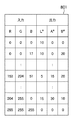
ステップS1902において、データ処理部205は、再現性を重視する色の指定を受け付けるUI画面1801で指定された情報に基づいて、RGB値の抽出を行う。特定の色の再現性を強調するためのRGB値の抽出方法としては、例えば、UI画面1801の各色に対応する複数の色候補のデータを図20に示す表2001に準備しておき、RGB値の抽出処理の実行時に、表2001を参照するようにしてもよい。図20に示す表2001はデータ処理部205により参照可能な状態で記憶部202に格納されているものとする。表2001には、色候補1、色候補2、色候補3が格納されており、ユーザの選択した色に応じた色候補が読み出される。ここで色候補は1〜3としているが、色候補の数はいくつあっても問題は無い。また表2001では全ての色に対して色候補1〜色候補3が定義されているが、「薄い赤」、「濃い赤」などの色に応じて色候補の数が変わっても問題は無い。RGB値の抽出処理の実行時に、データ処理部205はユーザの指定に基づいて、対応する色の色候補1、色候補2、色候補3のRGB値を全て読み出す。例えばユーザが「薄い赤」を選択した場合、色候補1(255,240,240)、色候補2(255,220,220)、色候補3(255,200,200)が読み出される。複数の色を指定した場合は複数の色に対応した色候補1〜3が全て読み出される。S1902の処理により抽出されたRGB値は記憶部202に格納される(S706)。
In step S1902, the
S708において、データ処理部205は、デバイス変動量LUT713、714、715と、キャリブレーション経過時間716、717、718とに基づき、新しいデバイス変動量LUTを生成する。
In step S708, the
ステップS709で、データ処理部205は、S708で生成された新デバイス変動量LUTを記憶部202に格納する。
In step S709, the
ステップS710で、データ処理部205は、記憶部202に格納されたユーザが選択した色に対応する複数の色候補からなるRGB値と、新デバイス変動量LUTと、を読み出す。そして、データ処理部205は、新デバイス変動量LUTを用いて、S1902の処理により抽出されたRGB値を、色再現性の変動量を示すデータ(L*a*b*)に変換する。
In step S <b> 710, the
ステップS711において、データ処理部205は、変換処理の結果により得られたL*、a*、b*値に基づき、例えば、(2)式を利用して、色再現性の変動量の大小を評価するための評価パラメータを算出する。そして、データ処理部205は、評価パラメータを順次加算してき、評価パラメータの総和を求める。ここでは総和に限らず、最大値や平均などを用いても問題は無い。
In step S711, the
S712において、表示部204は、データ処理部205の表示制御の下、L*、a*、b*の値に基づく評価パラメータの総和の小さい順にユーザインタフェース(UI)にデバイス名を表示し、処理を終了する。ユーザによる色の指定が反映された評価結果がUI画面に表示される。
In step S712, the
本実施形態では、リモートコピーを例として説明したが、ドライバ出力を行う場合でも、ユーザによる色の指定を色再現性の変動評価に反映することができる。本実施形態に拠れば、ユーザによる色の指定を反映したRGB値の出現頻度に応じて色再現性の変動量の少ないデバイスを選択することが可能になる。 In this embodiment, the remote copy has been described as an example. However, even when driver output is performed, the color designation by the user can be reflected in the color reproducibility fluctuation evaluation. According to the present embodiment, it is possible to select a device with a small amount of variation in color reproducibility according to the appearance frequency of RGB values reflecting the color designation by the user.
(他の実施形態)
なお、本発明の目的は、前述した実施形態の機能を実現するソフトウェアのプログラムコードを記録したコンピュータ可読の記憶媒体を、システムあるいは装置に供給することによっても、達成されることは言うまでもない。また、システムあるいは装置のコンピュータ(またはCPUやMPU)が記憶媒体に格納されたプログラムコードを読出し実行することによっても、達成されることは言うまでもない。
(Other embodiments)
Needless to say, the object of the present invention can also be achieved by supplying a system or apparatus with a computer-readable storage medium storing software program codes for realizing the functions of the above-described embodiments. Needless to say, this can also be achieved by the computer (or CPU or MPU) of the system or apparatus reading and executing the program code stored in the storage medium.
この場合、記憶媒体から読出されたプログラムコード自体が前述した実施形態の機能を実現することになり、そのプログラムコードを記憶した記憶媒体は本発明を構成することになる。 In this case, the program code itself read from the storage medium realizes the functions of the above-described embodiments, and the storage medium storing the program code constitutes the present invention.
プログラムコードを供給するための記憶媒体としては、例えば、フレキシブルディスク、ハードディスク、光ディスク、光磁気ディスク、CD−ROM、CD−R、不揮発性のメモリカード、ROMなどを用いることができる。 As a storage medium for supplying the program code, for example, a flexible disk, a hard disk, an optical disk, a magneto-optical disk, a CD-ROM, a CD-R, a nonvolatile memory card, a ROM, or the like can be used.
また、コンピュータが読出したプログラムコードを実行することにより、前述した実施形態の機能が実現される。また、プログラムコードの指示に基づき、コンピュータ上で稼働しているOS(オペレーティングシステム)などが実際の処理の一部または全部を行い、その処理によって前述した実施形態が実現される場合も含まれることは言うまでもない。 Further, the functions of the above-described embodiment are realized by executing the program code read by the computer. In addition, an OS (operating system) running on a computer performs part or all of actual processing based on an instruction of a program code, and the above-described embodiment is realized by the processing. Needless to say.
201 像読み取り部
202 記憶部
203 記録部
表示部 204
205 データ処理部
206 入力部
207 ネットワークインタフェース
201
205
Claims (16)
前記補間手段による前記補間の結果に基づき、出力すべき画像データに対する画質の変動量を前記複数の画像形成デバイスそれぞれに対して算出する算出手段と、
前記算出手段の算出結果に基づき、前記画像データの出力先として前記複数の画像形成デバイスの優先順位を決定する決定手段と、
前記決定手段により決定された前記優先順位に従って、前記複数の画像形成デバイスの中から選択が可能な画像形成デバイスをリスト表示する表示手段と
を備えることを特徴とする画像処理装置。 Interpolation means for interpolating the amount of fluctuation in image quality of each of a plurality of image forming devices capable of outputting image data based on the result of image formation at the time of calibration execution and the result of image formation after the execution of calibration ,
Based on the result of the interpolation by the interpolation means, a calculation means for calculating a variation amount of image quality for the image data to be output for each of the plurality of image forming devices;
A determining unit that determines a priority order of the plurality of image forming devices as an output destination of the image data based on a calculation result of the calculating unit;
An image processing apparatus comprising: display means for displaying a list of image forming devices that can be selected from the plurality of image forming devices in accordance with the priority order determined by the determining means.
前記抽出手段により抽出された輝度の情報を入力とし、前記補間手段により補間された前記変動量を出力とした、1次元ルックアップテーブルに基づき、前記算出手段は、前記輝度の情報の変動量を算出することを特徴とする請求項2に記載の画像処理装置。 The extraction means extracts luminance information from the monochrome image data to be output,
Based on a one-dimensional look-up table in which the luminance information extracted by the extraction unit is input and the variation amount interpolated by the interpolation unit is output, the calculation unit calculates the variation amount of the luminance information. The image processing apparatus according to claim 2, wherein the calculation is performed.
前記決定手段は、前記算出手段の算出結果と、前記判定手段の判定結果と、に基づき、前記複数の画像形成デバイスの優先順位を決定することを特徴とする請求項2または3に記載の画像処理装置。 A determination means for determining whether or not the RGB values extracted by the extraction means are within a range reproducible by the plurality of image forming devices;
4. The image according to claim 2, wherein the determination unit determines a priority order of the plurality of image forming devices based on a calculation result of the calculation unit and a determination result of the determination unit. 5. Processing equipment.
前記算出手段の算出結果が複数の画像形成デバイスで同一となった場合に、前記決定手段は、前記取得手段により取得された前記デバイス情報に基づき、当該算出結果が同一となった複数の画像形成デバイスの優先順位を決定することを特徴とする請求項1に記載の画像処理装置。 An acquisition means for acquiring device information for evaluating the performance of the plurality of image forming devices;
When the calculation result of the calculation unit is the same for a plurality of image forming devices, the determination unit is configured to generate a plurality of image formations with the same calculation result based on the device information acquired by the acquisition unit. The image processing apparatus according to claim 1, wherein priority order of devices is determined.
前記指定手段により前記特定の色が指定された場合に、前記抽出手段は、前記カラー画像データから対応する色の色候補を抽出することを特徴とする請求項2に記載の画像処理装置。 In order to emphasize the reproducibility of a specific color, it further comprises a specifying means for receiving the specification of the specific color,
The image processing apparatus according to claim 2, wherein when the specific color is designated by the designation unit, the extraction unit extracts a color candidate of a corresponding color from the color image data.
算出手段が、前記補間工程による前記補間の結果に基づき、出力すべき画像データに対する画質の変動量を前記複数の画像形成デバイスそれぞれに対して算出する算出工程と、
決定手段が、前記算出工程の算出結果に基づき、前記画像データの出力先として前記複数の画像形成デバイスの優先順位を決定する決定工程と、
表示手段が、前記決定工程により決定された前記優先順位に従って、前記複数の画像形成デバイスの中から選択が可能な画像形成デバイスをリスト表示する表示工程と
を有することを特徴とする画像処理装置の制御方法。 Interpolation means interpolates the amount of fluctuation in image quality of each of a plurality of image forming devices capable of outputting image data based on the result of image formation at the time of calibration execution and the result of image formation after the execution of calibration. An interpolation process to
A calculating step in which a calculating unit calculates a variation amount of image quality for image data to be output for each of the plurality of image forming devices based on the result of the interpolation in the interpolation step;
A determination unit that determines a priority order of the plurality of image forming devices as an output destination of the image data based on a calculation result of the calculation step;
An image processing apparatus comprising: a display unit configured to display a list of image forming devices that can be selected from the plurality of image forming devices according to the priority order determined in the determining step. Control method.
前記抽出工程により抽出された輝度の情報を入力とし、前記補間工程により補間された前記変動量を出力とした、1次元ルックアップテーブルに基づき、前記算出工程では、前記輝度の情報の変動量を算出することを特徴とする請求項9に記載の画像処理装置の制御方法。 In the extraction step, luminance information is extracted from the monochrome image data to be output,
Based on a one-dimensional look-up table with the luminance information extracted by the extraction step as an input and the variation amount interpolated by the interpolation step as an output, the calculation step calculates the variation amount of the luminance information. The method of controlling an image processing apparatus according to claim 9 , wherein calculation is performed.
前記決定工程では、前記算出工程の算出結果と、前記判定工程の判定結果と、に基づき、前記複数の画像形成デバイスの優先順位を決定することを特徴とする請求項9または10に記載の画像処理装置の制御方法。 The determination unit further includes a determination step of determining whether or not the RGB values extracted by the extraction step are within a range that can be reproduced by the plurality of image forming devices,
In the determination step, the calculation result of the calculating step, based on a determination result of said determination step, an image according to claim 9 or 10, characterized in that to determine the priority of the plurality of image forming devices A method for controlling a processing apparatus.
前記算出工程の算出結果が複数の画像形成デバイスで同一となった場合に、前記決定工程では、前記取得工程により取得された前記デバイス情報に基づき、当該算出結果が同一となった複数の画像形成デバイスの優先順位を決定することを特徴とする請求項8に記載の画像処理装置の制御方法。 The acquisition unit further includes an acquisition step of acquiring device information for evaluating the performance of the plurality of image forming devices,
When the calculation result of the calculation step is the same for a plurality of image forming devices, the determination step is to form a plurality of image formations with the same calculation result based on the device information acquired by the acquisition step. 9. The method according to claim 8 , wherein the priority order of the devices is determined.
前記指定工程により前記特定の色が指定された場合に、前記抽出工程では、前記カラー画像データから対応する色の色候補を抽出することを特徴とする請求項9に記載の画像処理装置の制御方法。 The designation means further includes a designation step for accepting designation of the specific color in order to emphasize the reproducibility of the specific color;
10. The control of an image processing apparatus according to claim 9 , wherein when the specific color is designated by the designation step, the extraction step extracts a color candidate of a corresponding color from the color image data. Method.
Priority Applications (4)
| Application Number | Priority Date | Filing Date | Title |
|---|---|---|---|
| JP2007307895A JP4839298B2 (en) | 2007-11-28 | 2007-11-28 | Image processing apparatus, image processing apparatus control method, program, and storage medium |
| US12/270,914 US8170377B2 (en) | 2007-11-28 | 2008-11-14 | Image processing apparatus, control method of image processing apparatus, program, and storage medium |
| EP08170142.7A EP2066111B1 (en) | 2007-11-28 | 2008-11-27 | Image processing apparatus and control method |
| CN2008101793306A CN101448059B (en) | 2007-11-28 | 2008-11-28 | Image processing apparatus and control method thereof |
Applications Claiming Priority (1)
| Application Number | Priority Date | Filing Date | Title |
|---|---|---|---|
| JP2007307895A JP4839298B2 (en) | 2007-11-28 | 2007-11-28 | Image processing apparatus, image processing apparatus control method, program, and storage medium |
Publications (3)
| Publication Number | Publication Date |
|---|---|
| JP2009135604A JP2009135604A (en) | 2009-06-18 |
| JP2009135604A5 JP2009135604A5 (en) | 2010-02-12 |
| JP4839298B2 true JP4839298B2 (en) | 2011-12-21 |
Family
ID=40430151
Family Applications (1)
| Application Number | Title | Priority Date | Filing Date |
|---|---|---|---|
| JP2007307895A Expired - Fee Related JP4839298B2 (en) | 2007-11-28 | 2007-11-28 | Image processing apparatus, image processing apparatus control method, program, and storage medium |
Country Status (4)
| Country | Link |
|---|---|
| US (1) | US8170377B2 (en) |
| EP (1) | EP2066111B1 (en) |
| JP (1) | JP4839298B2 (en) |
| CN (1) | CN101448059B (en) |
Families Citing this family (5)
| Publication number | Priority date | Publication date | Assignee | Title |
|---|---|---|---|---|
| JP5901464B2 (en) * | 2012-04-18 | 2016-04-13 | 株式会社Pfu | Image processing system, information processing apparatus, display method, and computer program |
| JP2014033306A (en) * | 2012-08-02 | 2014-02-20 | Canon Inc | Image processing apparatus, and image forming method and program |
| WO2015025575A1 (en) * | 2013-08-23 | 2015-02-26 | ソニー株式会社 | Signal generating device, signal generating program, signal generating method, and image display device |
| JP6501621B2 (en) * | 2015-05-29 | 2019-04-17 | キヤノン株式会社 | IMAGE PROCESSING APPARATUS, IMAGE PROCESSING METHOD, AND IMAGE PROCESSING PROGRAM THEREOF |
| US9917985B2 (en) * | 2016-04-29 | 2018-03-13 | Konica Minolta Laboratory U.S.A., Inc. | Method and system for checking color among a printer having an in-line sensor and printers without an in-line sensor |
Family Cites Families (23)
| Publication number | Priority date | Publication date | Assignee | Title |
|---|---|---|---|---|
| US5712890A (en) * | 1994-11-23 | 1998-01-27 | Thermotrex Corp. | Full breast digital mammography device |
| US5886353A (en) * | 1995-04-21 | 1999-03-23 | Thermotrex Corporation | Imaging device |
| US5989835A (en) * | 1997-02-27 | 1999-11-23 | Cellomics, Inc. | System for cell-based screening |
| DE69835319T2 (en) | 1997-06-20 | 2007-08-02 | Seiko Epson Corp. | Printing system and printing method for selecting an optimal printer for printing |
| WO1999058927A1 (en) * | 1998-05-08 | 1999-11-18 | Sony Corporation | Image generating device and method |
| US6219099B1 (en) * | 1998-09-23 | 2001-04-17 | Honeywell International Inc. | Method and apparatus for calibrating a display using an array of cameras |
| US6864995B2 (en) * | 2000-02-29 | 2005-03-08 | Fuji Photo Film Co., Ltd. | Gradation correction curve producing method, gradation correction curve producing apparatus, and gradation correction curve producing program storage medium |
| US6804406B1 (en) * | 2000-08-30 | 2004-10-12 | Honeywell International Inc. | Electronic calibration for seamless tiled display using optical function generator |
| JP2002118763A (en) * | 2000-10-06 | 2002-04-19 | Ricoh Co Ltd | Color image output method and color image output device |
| US6985637B1 (en) * | 2000-11-10 | 2006-01-10 | Eastman Kodak Company | Method and apparatus of enhancing a digital image using multiple selected digital images |
| JP2002366330A (en) * | 2001-06-11 | 2002-12-20 | Fujitsu Ltd | Print system and print management method |
| CN1237406C (en) * | 2001-09-27 | 2006-01-18 | 佳能株式会社 | Colour picture forming apparatus and controlling method thereof |
| US7348993B2 (en) * | 2003-11-10 | 2008-03-25 | Microsoft Corporation | System and method for obtaining accurate image content |
| JP2005242049A (en) * | 2004-02-27 | 2005-09-08 | Canon Inc | Color printing system |
| JP2006093987A (en) * | 2004-09-22 | 2006-04-06 | Fuji Xerox Co Ltd | Color patch providing method, color correction data providing method, electronic image data providing method, image forming method and system of these |
| JP2006094118A (en) * | 2004-09-24 | 2006-04-06 | Fuji Xerox Co Ltd | Image processing apparatus, image processing method and program thereof |
| JP2006088521A (en) * | 2004-09-24 | 2006-04-06 | Fuji Xerox Co Ltd | Image outputting apparatus, output controlling apparatus, output controlling method and its program |
| JP2006154944A (en) * | 2004-11-25 | 2006-06-15 | Canon Inc | Image output controller |
| JP2006168200A (en) | 2004-12-16 | 2006-06-29 | Canon Inc | Printing system |
| JP2007152859A (en) * | 2005-12-07 | 2007-06-21 | Konica Minolta Business Technologies Inc | Image forming apparatus and data backup processing program |
| JP2007221182A (en) * | 2006-02-14 | 2007-08-30 | Fuji Xerox Co Ltd | Apparatus, program and method of processing image |
| US8373894B2 (en) * | 2006-05-09 | 2013-02-12 | Xerox Corporation | System and method for selecting a proof printer for a given production printer |
| US7702229B2 (en) * | 2006-10-18 | 2010-04-20 | Eastman Kodak Company | Lens array assisted focus detection |
-
2007
- 2007-11-28 JP JP2007307895A patent/JP4839298B2/en not_active Expired - Fee Related
-
2008
- 2008-11-14 US US12/270,914 patent/US8170377B2/en not_active Expired - Fee Related
- 2008-11-27 EP EP08170142.7A patent/EP2066111B1/en not_active Not-in-force
- 2008-11-28 CN CN2008101793306A patent/CN101448059B/en not_active Expired - Fee Related
Also Published As
| Publication number | Publication date |
|---|---|
| EP2066111A3 (en) | 2010-09-22 |
| CN101448059B (en) | 2011-11-30 |
| EP2066111B1 (en) | 2013-06-05 |
| US8170377B2 (en) | 2012-05-01 |
| EP2066111A2 (en) | 2009-06-03 |
| CN101448059A (en) | 2009-06-03 |
| US20090136124A1 (en) | 2009-05-28 |
| JP2009135604A (en) | 2009-06-18 |
Similar Documents
| Publication | Publication Date | Title |
|---|---|---|
| US7369271B2 (en) | Image processing apparatus and its method, and control method | |
| CN103826029B (en) | Color image processing apparatus and its control method | |
| EP1365579B1 (en) | Image processing apparatus, method and program | |
| JP5631060B2 (en) | Image processing apparatus, image processing method, and program for executing image processing method | |
| JP4902331B2 (en) | Image processing apparatus, server apparatus, display method, data processing method, storage medium, program | |
| JP5731847B2 (en) | Image processing apparatus and image processing method | |
| JP5968132B2 (en) | Image processing apparatus, image processing method, and program | |
| CN102035993B (en) | Image processor, image forming system, image processing method | |
| JP5782804B2 (en) | Image processing apparatus, image processing method, and program | |
| KR101672075B1 (en) | Image processing apparatus, image processing method, and computer readable storage medium | |
| KR20140109322A (en) | Color image processing apparatus and method for processing color image | |
| JP4839298B2 (en) | Image processing apparatus, image processing apparatus control method, program, and storage medium | |
| JP5984530B2 (en) | Image processing apparatus, image processing method, and program thereof | |
| JP4793185B2 (en) | Image processing apparatus and program | |
| JP2012105233A (en) | Color conversion method, color conversion device and image formation system | |
| JP4550727B2 (en) | Image processing apparatus and image forming apparatus | |
| JP2020203454A (en) | Image processing device and image forming device | |
| JP2007194810A (en) | Image processing device | |
| JP3880467B2 (en) | Image processing apparatus and method, and control method | |
| JP2006094296A (en) | Image processing apparatus, image forming apparatus, image processing method and program | |
| JP6526134B2 (en) | Image forming apparatus, control method therefor, and computer program | |
| JP2013115730A (en) | Image processing apparatus, image processing method and program | |
| JP2013109496A (en) | Print condition selection device, print condition selection method, and program | |
| JP2006086843A (en) | Electronic image data providing method and system thereof | |
| JP2014110615A (en) | Image processing device and image forming device |
Legal Events
| Date | Code | Title | Description |
|---|---|---|---|
| A521 | Written amendment |
Free format text: JAPANESE INTERMEDIATE CODE: A523 Effective date: 20091218 |
|
| A621 | Written request for application examination |
Free format text: JAPANESE INTERMEDIATE CODE: A621 Effective date: 20091218 |
|
| A977 | Report on retrieval |
Free format text: JAPANESE INTERMEDIATE CODE: A971007 Effective date: 20110608 |
|
| A131 | Notification of reasons for refusal |
Free format text: JAPANESE INTERMEDIATE CODE: A131 Effective date: 20110617 |
|
| A521 | Written amendment |
Free format text: JAPANESE INTERMEDIATE CODE: A523 Effective date: 20110623 |
|
| TRDD | Decision of grant or rejection written | ||
| A01 | Written decision to grant a patent or to grant a registration (utility model) |
Free format text: JAPANESE INTERMEDIATE CODE: A01 Effective date: 20110905 |
|
| A01 | Written decision to grant a patent or to grant a registration (utility model) |
Free format text: JAPANESE INTERMEDIATE CODE: A01 |
|
| A61 | First payment of annual fees (during grant procedure) |
Free format text: JAPANESE INTERMEDIATE CODE: A61 Effective date: 20111003 |
|
| FPAY | Renewal fee payment (event date is renewal date of database) |
Free format text: PAYMENT UNTIL: 20141007 Year of fee payment: 3 |
|
| FPAY | Renewal fee payment (event date is renewal date of database) |
Free format text: PAYMENT UNTIL: 20141007 Year of fee payment: 3 |
|
| LAPS | Cancellation because of no payment of annual fees |