JP4839010B2 - Analysis system, data processing apparatus, and application program - Google Patents

Analysis system, data processing apparatus, and application program Download PDF

Info

Publication number
JP4839010B2
JP4839010B2 JP2005094074A JP2005094074A JP4839010B2 JP 4839010 B2 JP4839010 B2 JP 4839010B2 JP 2005094074 A JP2005094074 A JP 2005094074A JP 2005094074 A JP2005094074 A JP 2005094074A JP 4839010 B2 JP4839010 B2 JP 4839010B2
Authority
JP
Japan
Prior art keywords
measurement
data
analysis result
item
measurement item
Prior art date
Legal status (The legal status is an assumption and is not a legal conclusion. Google has not performed a legal analysis and makes no representation as to the accuracy of the status listed.)
Expired - Fee Related
Application number
JP2005094074A
Other languages
Japanese (ja)
Other versions
JP2006275707A (en
JP2006275707A5 (en
Inventor
義博 三島
照貴 屋内
Current Assignee (The listed assignees may be inaccurate. Google has not performed a legal analysis and makes no representation or warranty as to the accuracy of the list.)
Sysmex Corp
Original Assignee
Sysmex Corp
Priority date (The priority date is an assumption and is not a legal conclusion. Google has not performed a legal analysis and makes no representation as to the accuracy of the date listed.)
Filing date
Publication date
Application filed by Sysmex Corp filed Critical Sysmex Corp
Priority to JP2005094074A priority Critical patent/JP4839010B2/en
Priority to US11/392,085 priority patent/US20060265173A1/en
Publication of JP2006275707A publication Critical patent/JP2006275707A/en
Publication of JP2006275707A5 publication Critical patent/JP2006275707A5/ja
Priority to US12/381,944 priority patent/US20090259408A1/en
Application granted granted Critical
Publication of JP4839010B2 publication Critical patent/JP4839010B2/en
Expired - Fee Related legal-status Critical Current
Anticipated expiration legal-status Critical

Links

Images

Classifications

    • GPHYSICS
    • G01MEASURING; TESTING
    • G01NINVESTIGATING OR ANALYSING MATERIALS BY DETERMINING THEIR CHEMICAL OR PHYSICAL PROPERTIES
    • G01N15/00Investigating characteristics of particles; Investigating permeability, pore-volume, or surface-area of porous materials
    • G01N15/10Investigating individual particles
    • G01N15/14Electro-optical investigation, e.g. flow cytometers
    • G01N15/1468Electro-optical investigation, e.g. flow cytometers with spatial resolution of the texture or inner structure of the particle
    • G01N15/147Electro-optical investigation, e.g. flow cytometers with spatial resolution of the texture or inner structure of the particle the analysis being performed on a sample stream
    • GPHYSICS
    • G01MEASURING; TESTING
    • G01NINVESTIGATING OR ANALYSING MATERIALS BY DETERMINING THEIR CHEMICAL OR PHYSICAL PROPERTIES
    • G01N35/00Automatic analysis not limited to methods or materials provided for in any single one of groups G01N1/00 - G01N33/00; Handling materials therefor
    • G01N35/00584Control arrangements for automatic analysers
    • G01N35/00722Communications; Identification
    • G01N2015/012
    • G01N2015/016
    • G01N2015/018
    • GPHYSICS
    • G01MEASURING; TESTING
    • G01NINVESTIGATING OR ANALYSING MATERIALS BY DETERMINING THEIR CHEMICAL OR PHYSICAL PROPERTIES
    • G01N15/00Investigating characteristics of particles; Investigating permeability, pore-volume, or surface-area of porous materials
    • G01N15/10Investigating individual particles
    • G01N15/14Electro-optical investigation, e.g. flow cytometers
    • G01N2015/1486Counting the particles
    • GPHYSICS
    • G01MEASURING; TESTING
    • G01NINVESTIGATING OR ANALYSING MATERIALS BY DETERMINING THEIR CHEMICAL OR PHYSICAL PROPERTIES
    • G01N35/00Automatic analysis not limited to methods or materials provided for in any single one of groups G01N1/00 - G01N33/00; Handling materials therefor
    • G01N35/00584Control arrangements for automatic analysers
    • G01N35/00722Communications; Identification
    • G01N2035/00891Displaying information to the operator
    • G01N2035/0091GUI [graphical user interfaces]

Description

本発明は、検体に対する測定に使用される分析システム、当該分析システムに使用されるデータ処理装置、及びコンピュータをデータ処理装置として機能させるためのアプリケーションプログラムに関する。   The present invention relates to an analysis system used for measurement of a specimen, a data processing device used for the analysis system, and an application program for causing a computer to function as a data processing device.

血液分析装置、尿分析装置、粒子分析装置といった血液検体、尿検体、又は粒子検体等の様々な性状についての項目を測定する測定装置が知られている。この種の測定装置は、測定データを処理し、また測定結果、分析結果を管理することが必要となるため、かかる用途に用いられるアプリケーションプログラムがインストールされたコンピュータによって構成されるデータ処理装置を測定装置とは別に設け、このデータ処理装置に測定データの処理、並びに測定結果の表示及び管理を行わせる構成となっていることが多い(例えば、特許文献1参照)。   2. Description of the Related Art There are known measuring apparatuses that measure items related to various properties such as blood specimens, urine specimens, and particulate specimens, such as blood analyzers, urine analyzers, and particle analyzers. Since this type of measurement device needs to process measurement data and manage measurement results and analysis results, it measures a data processing device composed of a computer in which an application program used for such applications is installed. It is often provided separately from the apparatus, and the data processing apparatus is often configured to process measurement data and display and manage measurement results (see, for example, Patent Document 1).

また、複数の自動化学分析装置(測定装置)と自動化学分析装置の数より少ないデータ処理装置とを備え、複数の自動化学分析装置に対して一つのデータ処理装置を兼用した検査システムが開示されている(特許文献2参照)。この検査システムでは、複数の異なる種類の自動化学分析装置で一つのデータ処理装置を兼用することが可能である。   Also disclosed is an inspection system that includes a plurality of automatic chemical analyzers (measuring devices) and fewer data processing devices than the number of automatic chemical analyzers, and also uses a single data processing device for a plurality of automatic chemical analyzers. (See Patent Document 2). In this inspection system, a plurality of different types of automatic chemical analyzers can be used as one data processor.

上記のような分析システムにおいては、検査技師等のユーザが、データ処理装置を使用して分析結果を参照し、分析結果が外部に報告すべきものとして妥当か否かを判断し、妥当である場合にはその分析結果の外部への出力を確定する(バリデーション)。このようにバリデートされた分析結果は、検体毎に分析結果を管理するデータベースサーバ(ホストコンピュータ)へ送信され、データベースに登録される。データ処理装置には、測定データのような分析結果のデータ以上の分析情報が格納されており、かかるバリデート処理では、ユーザが分析結果だけでなく、測定データ等の詳細な情報を参照し、この分析結果の妥当性を判断する。   In the analysis system as described above, a user such as an inspection engineer uses a data processing device to refer to the analysis result and determines whether the analysis result is valid as to be reported to the outside. Confirm the output of the analysis results to the outside (validation). The analysis result validated in this way is transmitted to a database server (host computer) that manages the analysis result for each sample, and is registered in the database. The data processing apparatus stores analysis information more than analysis result data such as measurement data. In such validation processing, the user refers to detailed information such as measurement data as well as analysis results. Judge the validity of the analysis results.

特開2003−202346号公報JP 2003-202346 A 特開平5−307041号公報JP-A-5-307041

バリデート済みの分析結果の妥当性の観点から、ユーザが分析結果をバリデートするために用いる判断材料は多いほど好ましいが、上述したような従来の分析システムにおいては、ユーザは1種類の測定装置による測定結果のみを参照してバリデートを行っており、他の種類の測定装置による測定データは用いられていなかった。また、他の種類の測定装置による測定データをバリデートの判断に利用する場合には、ユーザは他のデータ処理装置のデータを確認する必要があり、煩雑な手間を要していた。   From the viewpoint of the validity of the validated analysis result, it is preferable that the judgment material used by the user to validate the analysis result is more preferable. However, in the conventional analysis system as described above, the user performs measurement using one type of measuring device. Validation was performed only by referring to the results, and measurement data obtained by other types of measurement devices were not used. In addition, when using measurement data from another type of measurement device for validation, the user needs to check the data of the other data processing device, which is troublesome.

本発明は、かかる事情に鑑みてなされたものであり、容易に複数種類の測定装置の測定結果を確認して分析結果のバリデートを行うことができる分析システム、データ処理装置、及びアプリケーションプログラムを提供することを目的とする。   The present invention has been made in view of such circumstances, and provides an analysis system, a data processing device, and an application program that can easily check the measurement results of a plurality of types of measurement devices and validate the analysis results. The purpose is to do.

本発明に係る分析システムは、検体に対して複数の測定項目を含む第1測定項目グループの測定を行って各測定項目に対応する各測定値データを取得するための第1測定装置と、検体に対して前記第1測定項目グループとは異なる複数の測定項目を含む第2測定項目グループの測定を行って各測定項目に対応する各測定値データを取得するための第2測定装置と、前記第1及び第2測定装置の夫々とネットワークを介して接続され、第1及び第2測定装置の夫々の測定動作を開始させることが可能なデータ処理装置とを備えた分析システムであって、前記データ処理装置は、前記第1測定装置からネットワークを介して前記第1測定項目グループの各測定項目に対応する各測定値データを受信するとともに、前記第2測定装置からネットワークを介して前記第2測定項目グループの各測定項目に対応する各測定値データを受信する受信手段と、前記第1測定項目グループの各測定項目に対応する各測定値データを分析処理して前記第1測定項目グループの各測定項目の各測定値を第1分析結果として取得するとともに、前記第2測定項目グループの各測定項目に対応する各測定値データを分析処理して前記第2測定項目グループの各測定項目の各測定値を第2分析結果として取得する分析処理手段と、前記第1測定装置による第1測定項目グループの各測定項目の各測定値である第1分析結果および前記第2測定装置による第2測定項目グループの各測定項目の各測定値である第2分析結果を格納する測定結果データベースと、入力手段と、前記測定結果データベースに格納された各第1分析結果または各第2分析結果を表示する分析結果表示領域と、入力手段を介して選択されると前記各第1分析結果を前記分析結果表示領域に表示させる第1選択手段および入力手段を介して選択されると前記各第2分析結果を前記分析結果表示領域に表示させる第2選択手段を含む分析結果表示切換手段とを含む分析結果表示画面を表示する表示手段と、前記第1又は第2選択手段の選択によって前記分析結果表示領域に表示された各第1又は各第2分析結果のうち、入力手段によって選択された一の第1又は第2分析結果のバリデートを行うためのバリデート手段と、を備えることを特徴とする。 An analysis system according to the present invention includes a first measurement device for performing measurement of a first measurement item group including a plurality of measurement items on a sample and acquiring each measurement value data corresponding to each measurement item, and the sample A second measurement device for performing measurement of a second measurement item group including a plurality of measurement items different from the first measurement item group and acquiring each measurement value data corresponding to each measurement item ; is connected via a respective network of first and second measuring device, and an analytical system comprising a data processor capable of initiating the respective measurement operation of the first and second measuring device, wherein the data processing device is configured to receive the measurement value data corresponding to each measurement item of the first measurement item group through the network from the first measuring device, network from the second measuring device Receiving means for receiving the measurement data for each measurement item of the second measurement item group through the analyzes process the measured values data corresponding to each measurement item of the first measurement item group Each measurement value of each measurement item in the first measurement item group is acquired as a first analysis result , and each measurement value data corresponding to each measurement item in the second measurement item group is analyzed to perform the second measurement item. Analysis processing means for acquiring each measurement value of each measurement item of the group as a second analysis result , a first analysis result which is each measurement value of each measurement item of the first measurement item group by the first measurement device, and the first the measurement result database for storing the second analysis result by the second measuring device is the measurement of each measurement item of the second measurement field group input means, stored in said measurement results database An analysis result display area for displaying the first analysis result or the second analysis result, first selecting means and the input means for displaying said respective first analysis result is selected via the input means to the analysis result display area display means for displaying an analysis result display screen to the selected each second analysis result includes an analysis result display switching means including a second selection means to be displayed on the analysis result display area through the first Alternatively, for validating one first or second analysis result selected by the input means among the first or second analysis results displayed in the analysis result display area by the selection of the second selection means. And validating means.

これにより、一つのデータ処理装置を用いて複数種類の測定装置の測定値データ及びその分析結果が管理されるので、ユーザはこのデータ処理装置を用いて複数種類の測定装置の測定値データに基づく複数種類の分析結果を参照してそれぞれの分析結果をバリデートすることができ、容易なバリデート作業で従来に比して分析結果の妥当性判断の精度を向上させることができる
As a result, the measurement value data of a plurality of types of measurement devices and the analysis results thereof are managed using a single data processing device, so that the user can use the data processing device to base the measurement value data on a plurality of types of measurement devices. Each analysis result can be validated by referring to a plurality of types of analysis results, and the accuracy of the validity determination of the analysis results can be improved by a simple validation operation as compared with the conventional case .

上記発明においては、前記データ処理装置は、前記第1及び第2測定値データ並びに前記第1及び第2分析結果を格納する測定結果データベースを備える構成とすることが好ましい。この場合には、前記データ処理装置は、前記第1測定装置に対応した第1測定結果データベースと、前記第2測定装置に対応した第2測定結果データベースとを備える構成とすることができ、また、前記第1及び第2測定値データ並びに前記第1及び第2分析結果を格納する一つの測定結果データベースを備える構成とすることもできる。
In the above invention, it is preferable that the data processing device includes a measurement result database that stores the first and second measurement value data and the first and second analysis results. In this case, the data processing device may be configured to include a first measurement result database corresponding to the first measuring equipment, and a second measurement result database corresponding to the second measuring device, Moreover, it can also be set as the structure provided with one measurement result database which stores the said 1st and 2nd measured value data and the said 1st and 2nd analysis result.

上記発明においては、前記測定結果データベースは、検体を特定する検体特定情報と、その検体の第1及び第2分析結果とを対応付けて格納するように構成されていることが好ましい。また、この場合においては、前記表示手段は、第1及び/又は第2分析結果を検体特定情報と対応付けて表示させる構成とすることが好ましい。更に、前記表示手段は、前記第1分析結果と前記第2分析結果とを、切り替えて表示させように構成されていることが好ましい。かかる構成とすることにより、一つのデータ処理装置を用いて、複数種類の測定装置の測定値データに基づく複数種類の分析結果を測定の種類に対応させて表示させることができ、多種の測定装置の分析結果を単に一度に画面表示した場合のように分析結果を測定の種類に応じて分類しながら確認するといった手間をユーザにかけさせることがなく、ユーザが扱いやすいユーザインタフェースとすることが可能である。
In the above invention, the measurement result database is preferably configured to store the sample specifying information for specifying the sample and the first and second analysis results of the sample in association with each other. Further, in this case, the display means, it is preferable that the configuration of Ru the first and / or second analysis result is displayed in association with the sample identification information. Further, the display means, and said second ANALYSIS Results from the first analysis result, that is configured to Ru was displayed Te toggle preferred. With this configuration, a single data processing device can be used to display a plurality of types of analysis results based on the measurement value data of a plurality of types of measuring devices in correspondence with the types of measurement. without cause applied to the user time and effort to make sure while classified according to the type of measure the analysis result as in the case of displaying analysis results simply at once screen, the user to the easy-to-use user interface Is possible.

上記発明においては、前記第1測定装置から受信した前記第1測定値データのみを分析処理可能であり、分析処理することによって第1分析結果を取得する第1測定装置専用データ処理装置を更に備え、前記第1測定装置専用データ処理装置は、検体を特定する検体特定情報と、その検体の前記第1分析結果とを対応付けて表示させる表示手段を備え、前記データ処理装置の前記表示手段によって表示される画面と前記専用データ処理装置の前記表示手段によって表示される画面、それぞれ、前記第1分析結果の表示領域と、検体特定情報の表示領域とを含み、前記データ処理装置の前記表示手段によって表示される画面と前記第1測定装置専用データ処理装置の前記表示手段によって表示される画面とで、前記第1分析結果の表示領域および前記検体特定情報の表示領域の配置が同一であることが好ましい。これにより、第1測定装置専用データ処理装置とデータ処理装置とのユーザインタフェースが共通化され、ユーザに夫々のデータ処理装置間で共通の使用感を与えることができ、ユーザの利便性がより一層向上する。
In the above invention, it is possible analyze process only the first measurement data received from the first measuring device, further comprising a first measuring device dedicated data processing device for obtaining a first analysis result by analyzing process the first measuring device dedicated data processing device includes a sample specifying information for specifying the sample, a display means for displaying in association with the first analysis result of the specimen, by the display means of the data processing device The displayed screen and the screen displayed by the display means of the dedicated data processing apparatus each include a display area for the first analysis result and a display area for specimen specifying information, and the display of the data processing apparatus Display area of the first analysis result and a screen displayed by the display means of the data processing apparatus dedicated to the first measuring device. It is preferred arrangement of the display area of the fine said analyte specific information is the same. As a result, the user interface between the data processing device dedicated to the first measurement device and the data processing device is shared, and the user can have a common feeling among the respective data processing devices, thereby further improving user convenience. improves.

上記発明においては、前記データ処理装置は、前記第1及び第2測定装置の設定データを格納する設定用データベースを備える構成とすることが好ましい。この場合には、前記データ処理装置は、前記第1測定装置に対応する第1設定用データベースと、前記第2測定装置に対応する第2設定用データベースとを備える構成とすることも可能である。
In the above invention, it is preferable that the data processing device includes a setting database that stores setting data of the first and second measuring devices. In this case, the data processing device includes a first setting database corresponding to the first measuring equipment, it is also possible to adopt a configuration and a second setting database corresponding to the second measuring device is there.

上記発明においては、前記データ処理装置は、前記第1及び第2測定装置に対して検体を測定する動作を指示する動作指示手段をさらに備えることが好ましい。これにより、ユーザは一つのデータ処理装置を使用して各測定装置の動作指示を与えることができ、ユーザの利便性がより一層向上する。
In the above invention, it is preferable that the data processing apparatus further includes an operation instruction means for instructing the first and second measurement apparatuses to perform an operation of measuring a sample . Thereby, the user can give the operation instruction of each measuring device using one data processing device, and the convenience of the user is further improved.

本発明に係るデータ処理装置は検体に対して複数の測定項目を含む第1測定項目グループの測定を行って各測定項目に対応する各測定値データを取得するための第1測定装置及び検体に対して前記第1測定項目グループとは異なる複数の測定項目を含む第2測定項目グループの測定を行って各測定項目に対応する各測定値データを取得するための第2測定装置の夫々とネットワークを介して接続され、第1及び第2測定装置の夫々の測定動作を開始させることが可能なデータ処理装置であって、前記第1測定装置からネットワークを介して前記第1測定項目グループの各測定項目に対応する各測定値データを受信するとともに、前記第2測定装置からネットワークを介して前記第2測定項目グループの各測定項目に対応する各測定値データを受信する受信手段と、前記第1測定項目グループの各測定項目に対応する各測定値データを分析処理して前記第1測定項目グループの各測定項目の各測定値を第1分析結果として取得するとともに、前記第2測定項目グループの各測定項目に対応する各測定値データを分析処理して前記第2測定項目グループの各測定項目の各測定値を第2分析結果として取得する分析処理手段と、前記第1測定装置による第1測定項目グループの各測定項目の各測定値である第1分析結果および前記第2測定装置による第2測定項目グループの各測定項目の各測定値である第2分析結果を格納する測定結果データベースと、入力手段と、前記測定結果データベースに格納された各第1分析結果または各第2分析結果を表示する分析結果表示領域と、入力手段を介して選択されると前記各第1分析結果を前記分析結果表示領域に表示させる第1選択手段および入力手段を介して選択されると前記各第2分析結果を前記分析結果表示領域に表示させる第2選択手段を含む分析結果表示切換手段とを含む分析結果表示画面を表示する表示手段と、前記第1又は第2選択手段の選択によって前記分析結果表示領域に表示された各第1又は各第2分析結果のうち、入力手段によって選択された一の第1又は第2分析結果のバリデートを行うためのバリデート手段とを備えることを特徴とする。 A data processing apparatus according to the present invention includes a first measurement apparatus and a sample for performing measurement of a first measurement item group including a plurality of measurement items on a sample and acquiring each measurement value data corresponding to each measurement item. the second measuring device each network for obtaining the measurement value data corresponding to each measurement item measured the second measurement item group including a plurality of different measurement items from the first measurement item group for Are connected to each other through the data processing device and can start the respective measurement operations of the first and second measurement devices, each of the first measurement item groups from the first measurement device via the network. which receives the measurement values data corresponding to the measurement items, each measurement value data via the network from the second measuring device corresponding to each measurement item of the second measurement item group Receiving means for signals to, and acquires the respective measured value of each measurement item of the first measurement item the first measurement item group by analyzing processes each measurement data corresponding to each measurement item of the group as a first analysis result And an analysis processing means for analyzing each measurement value data corresponding to each measurement item of the second measurement item group and obtaining each measurement value of each measurement item of the second measurement item group as a second analysis result; The first analysis result which is each measurement value of each measurement item of the first measurement item group by the first measurement device and the second measurement value of each measurement item of the second measurement item group by the second measurement device the measurement result database for storing the results of analysis, the input means and the analysis result display area for displaying the measurement results each of the first analysis stored in the database result or the second analysis result, input means When selected via the first selection means and the input means for displaying the first analysis results in the analysis result display area, the second analysis results are displayed in the analysis result display area. Display means for displaying an analysis result display screen including analysis result display switching means including second selection means , and each first or each displayed in the analysis result display area by selection of the first or second selection means of the second analysis result, characterized in that it comprises, and validate means for performing one first or second analysis validated selected by the input means.

これにより、ユーザは一つのデータ処理装置を用いて、複数種類の測定装置の測定値データに基づく複数種類の分析結果を確認してそれぞれの分析結果をバリデートすることができ、容易なバリデート作業で従来に比して分析結果の妥当性判断の精度を向上させることができる。
As a result, the user can check a plurality of types of analysis results based on the measurement value data of a plurality of types of measurement devices using a single data processing device, and validate each analysis result. Compared to the prior art, the accuracy of the validity judgment of the analysis result can be improved.

本発明に係るアプリケーションプログラムは、測定装置の測定値データを処理するために使用されるアプリケーションプログラムにおいて、検体に対して複数の測定項目を含む第1測定項目グループの測定を行って各測定項目に対応する各測定値データを取得するための第1測定装置及び検体に対して前記第1測定項目グループとは異なる複数の測定項目を含む第2測定項目グループの測定を行って各測定項目に対応する各測定値データを取得するための第2測定装置の夫々とネットワークを介して接続され、第1及び第2測定装置の夫々の測定動作を開始させることが可能なコンピュータを、前記第1測定装置からネットワークを介して前記第1測定項目グループの各測定項目に対応する各測定値データを受信するとともに、前記第2測定装置からネットワークを介して前記第2測定項目グループの各測定項目に対応する各測定値データを受信する受信手段と、前記第1測定項目グループの各測定項目に対応する各測定値データを分析処理して前記第1測定項目グループの各測定項目の各測定値を第1分析結果として取得するとともに、前記第2測定項目グループの各測定項目に対応する各測定値データを分析処理して前記第2測定項目グループの各測定項目の各測定値を第2分析結果として取得する分析処理手段と、前記第1測定装置による第1測定項目グループの各測定項目の各測定値である第1分析結果および前記第2測定装置による第2測定項目グループの各測定項目の各測定値である第2分析結果を格納する測定結果データベースと、入力手段と、前記測定結果データベースに格納された各第1分析結果または各第2分析結果を表示する分析結果表示領域と、入力手段を介して選択されると前記各第1分析結果を前記分析結果表示領域に表示させる第1選択手段および入力手段を介して選択されると前記各第2分析結果を前記分析結果表示領域に表示させる第2選択手段を含む分析結果表示切換手段とを含む分析結果表示画面を表示する表示手段と、前記第1又は第2選択手段の選択によって前記分析結果表示領域に表示された各第1又は各第2分析結果のうち、入力手段によって選択された一の第1又は第2分析結果のバリデートを行うためのバリデート手段として機能させることを特徴とする。

An application program according to the present invention is an application program used for processing measurement value data of a measurement apparatus, and performs measurement of a first measurement item group including a plurality of measurement items on a sample to each measurement item. Corresponding to each measurement item by measuring a second measurement item group including a plurality of measurement items different from the first measurement item group for the first measurement device and the specimen for acquiring each corresponding measurement value data A computer connected to each of the second measurement devices for acquiring each measurement value data to be performed via the network and capable of starting the measurement operation of each of the first and second measurement devices is provided in the first measurement. which receives the measurement values data corresponding to each measurement item of the first measurement item group through the network from the device, the second measurement Receiving means for receiving the measurement data for each measurement item of the second measurement item group through a placed network from the analysis process each measurement data corresponding to each measurement item of the first measurement item group Then , each measurement value of each measurement item of the first measurement item group is acquired as a first analysis result , and each measurement value data corresponding to each measurement item of the second measurement item group is analyzed and processed . Analysis processing means for acquiring each measurement value of each measurement item of the two measurement item groups as a second analysis result , and a first analysis result that is each measurement value of each measurement item of the first measurement item group by the first measurement device and a measurement result database for storing the second analysis result is the measurement of each measurement item of the second measurement item group by the second measuring device, an input unit, the measurement result data An analysis result display area for displaying the over scan the first analysis result stored in the or each second analysis result, and displays the respective first analysis result is selected via the input means to the analysis result display area When selected via the first selection means and the input means, an analysis result display screen including analysis result display switching means including second selection means for displaying each second analysis result in the analysis result display area is displayed. One first or second analysis selected by the input means among the first or second analysis results displayed in the analysis result display area by the selection of the display means and the first or second selection means It is made to function as a validating means for validating the result .

これにより、ユーザは一つのコンピュータ(データ処理装置)を用いて、複数種類の測定装置の測定値データに基づく複数種類の分析結果を確認してそれぞれの分析結果をバリデートすることができ、容易なバリデート作業で従来に比して分析結果の妥当性判断の精度を向上させることができる。
Accordingly, the user can use a single computer (data processing device) to check a plurality of types of analysis results based on the measurement value data of a plurality of types of measurement devices and validate each analysis result. The validity of the analysis result can be improved in the validation work as compared with the conventional method.

本発明に係る分析システム、データ処理装置、及びアプリケーションプログラムによれば、ユーザは一つのデータ処理装置を用いて複数種類の測定装置の測定値データに基づく複数種類の分析結果を確認してそれぞれの分析結果をバリデートすることができ、容易なバリデート作業で従来に比して分析結果の妥当性判断の精度を向上させることができる等、本発明は優れた効果を奏する。


Analysis system according to the present invention, the data processing apparatus, and according to the application program, the user each of using one data processing device to check the plurality of types of analytical results based on the measured value data of a plurality of types of measurement devices The present invention has an excellent effect that the analysis result can be validated, and the accuracy of the validity judgment of the analysis result can be improved as compared with the conventional method by an easy validation work.


以下、本発明の実施の形態に係る分析システム、データ処理装置、測定装置、及びアプリケーションプログラムについて、図面を参照しながら具体的に説明する。
(実施の形態1)
図1は、本発明の実施の形態1に係る分析システムの構成を示す模式図である。図1に示すように、本実施の形態1に係る分析システム1は、血球分析装置2a,2bと、血球分析装置2a,2b用のデータ処理装置3と、血液凝固測定装置4a,4bと、血液凝固測定装置4a,4b用のデータ処理装置5と、血球分析装置2a,2b及び血液凝固測定装置4a,4bの全てに用いられるデータ処理装置6と、患者データ管理用のデータベースサーバ7とを主要な構成要素として構成されている。血球分析装置2a,2b、データ処理装置3、血液凝固測定装置4a,4b、データ処理装置5、データ処理装置6、及びデータベースサーバ7は、例えば、病院または病理検査施設等の医療機関の施設内に設けられている。また、例えば、血球分析装置2a,2b、データ処理装置3、血液凝固測定装置4a,4b、データ処理装置5、及びデータ処理装置6は、病理検査施設に設けられており、データベースサーバ7は、病院に設けられている等、分析システム1を構成する装置が複数の施設に別個に設けられていてもよい。また、血球分析装置2a,2b、データ処理装置3、血液凝固測定装置4a,4b、データ処理装置5、データ処理装置6、及びデータベースサーバ7は、互いにデータ通信が可能であるように、電話回線を使用した専用回線、LAN、またはインターネット等である通信ネットワークNWによって接続されている。
Hereinafter, an analysis system, a data processing device, a measurement device, and an application program according to an embodiment of the present invention will be specifically described with reference to the drawings.
(Embodiment 1)
FIG. 1 is a schematic diagram showing a configuration of an analysis system according to Embodiment 1 of the present invention. As shown in FIG. 1, the analysis system 1 according to the first embodiment includes blood cell analyzers 2a and 2b, a data processor 3 for blood cell analyzers 2a and 2b, blood coagulation measuring devices 4a and 4b, A data processing device 5 for blood coagulation measuring devices 4a and 4b, a data processing device 6 used for all of blood cell analyzers 2a and 2b and blood coagulation measuring devices 4a and 4b, and a database server 7 for managing patient data It is configured as a major component. The blood cell analyzers 2a and 2b, the data processing device 3, the blood coagulation measuring devices 4a and 4b, the data processing device 5, the data processing device 6, and the database server 7 are, for example, in a medical institution such as a hospital or a pathological examination facility. Is provided. Further, for example, the blood cell analyzers 2a and 2b, the data processing device 3, the blood coagulation measurement devices 4a and 4b, the data processing device 5 and the data processing device 6 are provided in a pathological examination facility, and the database server 7 The apparatus which comprises the analysis system 1 may be provided separately in several facilities, such as being provided in the hospital. Further, the blood cell analyzers 2a and 2b, the data processor 3, the blood coagulation measuring devices 4a and 4b, the data processor 5, the data processor 6 and the database server 7 are telephone lines so that they can communicate with each other. Are connected by a communication network NW such as a dedicated line using LAN, a LAN, or the Internet.

図2は、血球分析装置2a及びデータ処理装置3の外観構成を示す斜視図である。血球分析装置2a,2bは、血液検査に使用される装置であり、血液検体中に含まれる成分について所定の測定を行うことが可能であるように構成されている。図2では、一方の血球分析装置2aのみを図示しているが、本実施の形態1に係る分析システム1では、同一構成の2つの血球分析装置2a,2bがデータ処理装置3にデータの送受信が可能であるように接続されている。図3は、血球分析装置2a(2b)の構成を示すブロック図である。血球分析装置2a(2b)は、光学式検出部21と、RBC検出部22と、HGB検出部23と、IMI検出部24と、制御部25と、通信部28とを主要な構成要素として構成されている。制御部25は、CPU,ROM,RAM等から構成されており、血球分析装置2aの各種構成要素の動作制御を行うようになっている。通信部28は、例えばEthernet(登録商標)インタフェースであり、データ処理装置3,5,6との間でデータの送受信を行うことが可能である。   FIG. 2 is a perspective view showing the external configuration of the blood cell analyzer 2a and the data processor 3. As shown in FIG. The blood cell analyzers 2a and 2b are devices used for blood tests, and are configured to be able to perform predetermined measurements on components contained in blood samples. In FIG. 2, only one blood cell analyzer 2 a is illustrated, but in the analysis system 1 according to the first embodiment, two blood cell analyzers 2 a and 2 b having the same configuration are transmitted to and received from the data processor 3. Are connected to be possible. FIG. 3 is a block diagram showing the configuration of the blood cell analyzer 2a (2b). The blood cell analyzer 2a (2b) includes an optical detection unit 21, an RBC detection unit 22, an HGB detection unit 23, an IMI detection unit 24, a control unit 25, and a communication unit 28 as main components. Has been. The control unit 25 includes a CPU, a ROM, a RAM, and the like, and performs operation control of various components of the blood cell analyzer 2a. The communication unit 28 is, for example, an Ethernet (registered trademark) interface, and can transmit and receive data to and from the data processing devices 3, 5, and 6.

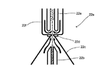
光学式検出部21は、白血球、有核赤血球、網赤血球を半導体レーザによるフローサイトメトリー法により測定することが可能である。図4は、光学式検出部21の構成を示す模式図である。血球分析装置2aは、図示しない試料供給部を有しており、当該試料供給部によって血液試料が吸引定量され、規定倍率で希釈、染色される。光学式検出部21には、シースフローセル21aが設けられており、前記試料供給部からシースフローセル21aに試料が供給されるようになっている。また、光学式検出部21には、図示しないシース液チャンバが設けられており、このシース液チャンバに貯められたシース液が、シースフローセル21aへと供給されるように構成されている。シースフローセル21aでは、シース液に取り囲まれるように試料が流れるようになっている。シースフローセル21aにはオリフィス21bが設けられており、このオリフィス21bによって試料の流れが細く絞り込まれ、試料に含まれる白血球、赤血球等の粒子が一つずつオリフィス21bを通過することとなる。   The optical detection unit 21 can measure white blood cells, nucleated red blood cells, and reticulocytes by a flow cytometry method using a semiconductor laser. FIG. 4 is a schematic diagram illustrating the configuration of the optical detection unit 21. The blood cell analyzer 2a has a sample supply unit (not shown). A blood sample is aspirated and quantified by the sample supply unit, and diluted and stained at a specified magnification. The optical detection unit 21 is provided with a sheath flow cell 21a, and a sample is supplied from the sample supply unit to the sheath flow cell 21a. In addition, the optical detection unit 21 is provided with a sheath liquid chamber (not shown), and the sheath liquid stored in the sheath liquid chamber is supplied to the sheath flow cell 21a. In the sheath flow cell 21a, the sample flows so as to be surrounded by the sheath liquid. The sheath flow cell 21a is provided with an orifice 21b. The orifice 21b narrows the flow of the sample finely, and particles such as white blood cells and red blood cells contained in the sample pass through the orifice 21b one by one.

光学式検出部21には、半導体レーザ光源が、シースフローセル21aのオリフィス21bへ向けてレーザ光を出射するように配置されている。半導体レーザ光源とシースフローセル21aとの間には、複数のレンズからなる照射レンズ系21cが配されている。この照射レンズ系21cによって、半導体レーザ光源から出射された平行ビームがビームスポットに集束されるようになっている。また、半導体レーザ光源からのレーザ光の光軸上には、シースフローセル21aを挟んで照射レンズ系21cに対向するように、ビームストッパ21dが設けられた前方散乱光集光レンズ21eが配されており、半導体レーザ光源からの直接光はビームストッパ21dによって遮光される。   In the optical detector 21, a semiconductor laser light source is disposed so as to emit laser light toward the orifice 21b of the sheath flow cell 21a. An irradiation lens system 21c composed of a plurality of lenses is disposed between the semiconductor laser light source and the sheath flow cell 21a. By this irradiation lens system 21c, the parallel beam emitted from the semiconductor laser light source is focused on the beam spot. A forward scattered light collecting lens 21e provided with a beam stopper 21d is arranged on the optical axis of the laser light from the semiconductor laser light source so as to face the irradiation lens system 21c with the sheath flow cell 21a interposed therebetween. The direct light from the semiconductor laser light source is shielded by the beam stopper 21d.

シースフローセル21aに試料が流れると、レーザ光により散乱光及び蛍光の光信号が発生する。このうち前方の信号光を前方散乱光集光レンズ21eで集めて後段の受光系に送るようになっている。受光系には、ピンホール21fが設けられており、さらに光軸下流側にはフォトダイオード21gが設けられている。前方散乱光集光レンズ21eから送られた信号光は、ピンホール21fによって迷光(測定以外の光)が除去された後、フォトダイオード21gで光電変換され、これによって生じた電気信号(前方散乱光信号)がアンプ21hによって増幅され、制御部25に出力される。かかる前方散乱光信号は、血球の大きさを反映しており、制御部25がこの前方散乱光信号を信号処理することによって、血球の大きさ等を得るようになっている。   When the sample flows through the sheath flow cell 21a, scattered light and fluorescent light signals are generated by the laser light. Among these, the front signal light is collected by the forward scattered light collecting lens 21e and sent to the light receiving system at the subsequent stage. The light receiving system is provided with a pinhole 21f, and further a photodiode 21g is provided downstream of the optical axis. The signal light transmitted from the forward scattered light condensing lens 21e is subjected to photoelectric conversion by the photodiode 21g after stray light (light other than measurement) is removed by the pinhole 21f, and an electric signal (forward scattered light) generated thereby. Signal) is amplified by the amplifier 21h and output to the control unit 25. The forward scattered light signal reflects the size of the blood cell, and the control unit 25 processes the forward scattered light signal to obtain the size of the blood cell.

また、シースフローセル21aの側方であって、照射レンズ系21c及び前方散乱光集光レンズ21eを結ぶ光軸に対して直行する方向には、側方集光レンズ21iが配されており、シースフローセル21a内を通過する血球に半導体レーザを照射したときに発生する側方光がこの側方集光レンズ21iで集められるようになっている。側方集光レンズ21iの下流側にはダイクロイックミラー21jが設けられており、側方集光レンズ21iから送られた信号光は、ダイクロイックミラー21jで散乱光成分と蛍光成分とに分けられる。ダイクロイックミラー21jの側方(側方集光レンズ21iとダイクロイックミラー21jを結ぶ光軸方向に交差する方向)には、側方散乱光受光用の光電子増倍管21kが設けられており、ダイクロイックミラー21jの前記光軸下流側には、光学フィルタ21m、ピンホール21n、及び光電子増倍管21oが設けられている。そして、ダイクロイックミラー21jで分けられた側方散乱光成分は、光電子増倍管21kで光電変換され、これによって生じた電気信号(側方散乱光信号)がアンプ21pによって増幅され、制御部25に出力される。この側方散乱光信号は、血球の内部情報(核の大きさ等)を反映しており、制御部25がこの側方散乱光信号を信号処理することによって、血球の核の大きさ等を得るようになっている。また、ダイクロイックミラー21jから発せられた側方蛍光成分は光学フィルタ21mによって波長選択された後、光電子増倍管21oで光電変換され、これによって生じた電気信号(側方蛍光信号)がアンプ21qによって増幅され、制御部25に出力される。この側方蛍光信号は、血球の染色度合いに関する情報を反映しており、この側方蛍光信号を信号処理することによって、血球の染色性等を得るようになっている。   In addition, a side condensing lens 21i is arranged on the side of the sheath flow cell 21a and in a direction perpendicular to the optical axis connecting the irradiation lens system 21c and the forward scattered light condensing lens 21e, and the sheath flow cell 21a. Lateral light generated when a semiconductor laser is irradiated to blood cells passing through the inside is collected by the lateral condenser lens 21i. A dichroic mirror 21j is provided on the downstream side of the side condenser lens 21i, and the signal light transmitted from the side condenser lens 21i is divided into a scattered light component and a fluorescent component by the dichroic mirror 21j. A photomultiplier tube 21k for receiving side scattered light is provided on the side of the dichroic mirror 21j (direction intersecting the optical axis direction connecting the side condenser lens 21i and the dichroic mirror 21j). On the downstream side of the optical axis, an optical filter 21m, a pinhole 21n, and a photomultiplier tube 21o are provided. Then, the side scattered light component divided by the dichroic mirror 21j is photoelectrically converted by the photomultiplier tube 21k, and an electric signal (side scattered light signal) generated thereby is amplified by the amplifier 21p, and is sent to the control unit 25. Is output. The side scattered light signal reflects internal information (nucleus size, etc.) of the blood cell, and the control unit 25 processes the side scattered light signal to determine the size of the blood cell nucleus, etc. To get. The side fluorescent component emitted from the dichroic mirror 21j is wavelength-selected by the optical filter 21m and then photoelectrically converted by the photomultiplier tube 21o, and an electric signal (side fluorescent signal) generated thereby is amplified by the amplifier 21q. Amplified and output to the control unit 25. This side fluorescent signal reflects information relating to the degree of staining of blood cells, and by processing the side fluorescent signals, the staining properties of blood cells and the like are obtained.

RBC検出部22は、赤血球数及び血小板数を、シースフローDC検出法により測定することが可能である。図5は、RBC検出部22の構成を示す模式図である。RBC検出部22は、図5に示すようなシースフローセル22aを有している。このシースフローセル22aには、上方へ向けて開口した試料ノズル22bが設けられており、試料供給部からこの試料ノズル22bに試料が供給されるようになっている。また、シースフローセル22aは、上方へ向かうにしたがって細くなっているテーパ状のチャンバ22cを有しており、このチャンバ22cの内部中央に前述した試料ノズル22bが配されている。また、チャンバ22cの上端には、アパーチャ22dが設けられており、このアパーチャ22dは、試料ノズル22bと中心位置が合わせられている。試料供給部から供給された試料は、試料ノズル22bの先端から上方へ向けて送出され、それと同時にチャンバ22cにはフロントシース液が供給され、フロントシース液がアパーチャ22dへ向けて上方へと流れる。ここで、フロントシース液に取り囲まれるように試料が流れ、テーパ状のチャンバ22cによって試料の流れが細く絞り込まれて、試料中の血球が一つずつアパーチャ22dを通過することとなる。アパーチャ22dには電極が設けられており、この電極間に直流電流が供給されるようになっている。そして、試料がアパーチャ22dを通流するときのアパーチャ22dにおける直流抵抗の変化を検出し、この電気信号を制御部25へ出力するようになっている。前記直流抵抗は、アパーチャ22dを血球が通過するときに増大するため、この電気信号はアパーチャ22dの血球の通過情報を反映しており、この電気信号を信号処理することによって、赤血球及び血小板を計数するようになっている。   The RBC detection unit 22 can measure the number of red blood cells and platelets by a sheath flow DC detection method. FIG. 5 is a schematic diagram illustrating a configuration of the RBC detection unit 22. The RBC detection unit 22 has a sheath flow cell 22a as shown in FIG. The sheath flow cell 22a is provided with a sample nozzle 22b opened upward, and a sample is supplied to the sample nozzle 22b from a sample supply unit. The sheath flow cell 22a has a tapered chamber 22c that becomes thinner toward the upper side, and the sample nozzle 22b described above is arranged at the center of the inside of the chamber 22c. Further, an aperture 22d is provided at the upper end of the chamber 22c, and the aperture 22d is aligned with the sample nozzle 22b in the center position. The sample supplied from the sample supply unit is sent upward from the tip of the sample nozzle 22b, and at the same time, the front sheath liquid is supplied to the chamber 22c, and the front sheath liquid flows upward toward the aperture 22d. Here, the sample flows so as to be surrounded by the front sheath liquid, the flow of the sample is narrowed down by the tapered chamber 22c, and blood cells in the sample pass through the aperture 22d one by one. The aperture 22d is provided with electrodes, and a direct current is supplied between the electrodes. Then, a change in DC resistance in the aperture 22d when the sample flows through the aperture 22d is detected, and this electric signal is output to the control unit 25. Since the DC resistance increases when a blood cell passes through the aperture 22d, the electrical signal reflects the passage information of the blood cell of the aperture 22d. By processing the electrical signal, red blood cells and platelets are counted. It is supposed to be.

また、アパーチャ22dの上方には、上下に延びた回収管22eが設けられている。また、この回収管22eは、アパーチャ22dを介してチャンバ22cと連なるチャンバ22fの内部に配されている。回収管22eの下端部は、チャンバ22fの内壁から離隔している。チャンバ22fは、バックシース液が供給されるようになっており、このバックシース液は、チャンバ22fの回収管22eの外側領域を下方へ向けて通流する。回収管22eの外側を流れるバックシース液は、チャンバ22fの下端部に到達した後、回収管22eの下端部とチャンバ22fの内壁との間を通り、回収管22eの内部へと流入する。このため、アパーチャ22dを通過した血球の舞い戻りが防止され、これにより血球の誤検出が防止される。   A recovery pipe 22e extending vertically is provided above the aperture 22d. Further, the recovery pipe 22e is disposed inside a chamber 22f connected to the chamber 22c via an aperture 22d. The lower end portion of the recovery pipe 22e is separated from the inner wall of the chamber 22f. The back sheath liquid is supplied to the chamber 22f, and the back sheath liquid flows downward in the outer region of the recovery tube 22e of the chamber 22f. The back sheath liquid flowing outside the recovery pipe 22e reaches the lower end of the chamber 22f, and then flows between the lower end of the recovery pipe 22e and the inner wall of the chamber 22f and flows into the recovery pipe 22e. For this reason, the blood cells that have passed through the aperture 22d are prevented from returning, thereby preventing erroneous detection of the blood cells.

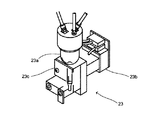
HGB検出部23は、血色素量(HGB)を、SLSヘモグロビン法によって測定することが可能である。図6は、HGB検出部23の構成を示す斜視図である。HGB検出部23は、希釈試料を収容するセル23aと、セル23aへ向けて発光する発光ダイオード23bと、セル23aを透過した透過光を受光する受光素子23cとを有している。試料供給部では、定量された血液が希釈液及び所定の溶血剤によって所定希釈率で希釈され、希釈試料が作成される。この溶血剤は、血液中のヘモグロビンをSLS−ヘモグロビンへと転化する性質を有している。かかる希釈試料は、試料供給部からセル23aへと供給され、セル23aに収容される。この状態で、発光ダイオード23bを発光させ、セル23aを挟んで発光ダイオード23bに対向配置された受光素子23cにて透過光が受光される。発光ダイオード23bは、SLS−ヘモグロビンによる吸光率が高い波長の光を発するようになっており、また、セル23aは透光性の高いプラスチック材料で構成されているので、受光素子23cでは、発光ダイオード23bの発光が略希釈試料によってのみ吸光された透過光が受光されることとなる。受光素子23cは、受光量(吸光度)に応じた電気信号を制御部25へと出力するようになっており、制御部25では、この吸光度と予め測定された希釈液のみの吸光度とを比較し、ヘモグロビン値を算出するようになっている。   The HGB detection unit 23 can measure the amount of hemoglobin (HGB) by the SLS hemoglobin method. FIG. 6 is a perspective view illustrating a configuration of the HGB detection unit 23. The HGB detection unit 23 includes a cell 23a that houses a diluted sample, a light emitting diode 23b that emits light toward the cell 23a, and a light receiving element 23c that receives transmitted light that has passed through the cell 23a. In the sample supply unit, the quantified blood is diluted with a diluent and a predetermined hemolytic agent at a predetermined dilution rate, and a diluted sample is created. This hemolytic agent has the property of converting hemoglobin in blood into SLS-hemoglobin. The diluted sample is supplied from the sample supply unit to the cell 23a and is stored in the cell 23a. In this state, the light emitting diode 23b is caused to emit light, and the transmitted light is received by the light receiving element 23c arranged to face the light emitting diode 23b with the cell 23a interposed therebetween. The light emitting diode 23b emits light having a wavelength with a high light absorption rate due to SLS-hemoglobin, and the cell 23a is made of a highly transparent plastic material. The transmitted light in which the emission of 23b is absorbed only by the substantially diluted sample is received. The light receiving element 23c outputs an electrical signal corresponding to the amount of received light (absorbance) to the control unit 25, and the control unit 25 compares this absorbance with the absorbance of only the diluted solution measured in advance. The hemoglobin value is calculated.

IMI検出部24は、検体中の幼若球の出現度合いをRF/DC検出法により測定することが可能である。図7は、IMI検出部24の構成を示す模式図である。IMI検出部24は、検出器チャンバ24aと、吸引チャンバ24bと、電極24c,24dに接続された直流電流供給回路24eと、電極24c,24dに接続された高周波電流供給回路24fとを有している。検出器チャンバ24aには、試料供給部によって吸引定量され、また所定倍率で希釈された血液試料が供給されるようになっている。また、検出器チャンバ24aと、吸引チャンバ24bとは隣接しており、両チャンバ24a,24bはアパーチャ24gを介して連通している。吸引チャンバ24bは、図示しないポンプに連通されており、このポンプによって希釈試料が吸引されるようになっている。吸引された希釈試料は、検出器チャンバ24aからアパーチャ24gを通って吸引チャンバ24bに流入する。また、電極24cは、検出器チャンバ24a内に設けられており、電極24dは、吸引チャンバ24b内に設けられている。直流電流供給回路24eは、抵抗24hと直流電源24iとが直列接続された回路であり、電極24c,24d間に直流電流を供給するようになっている。したがって、希釈試料が前記ポンプで吸引されているときには、この希釈試料に含まれる血球がアパーチャ24gを通過し、このときに電極24c,24d間の直流抵抗が変化することとなる。直流電流供給回路24eからは、この直流抵抗の変化を示す電気信号が制御部25に出力される。この直流抵抗の変化はアパーチャ24gを通過した血球の大きさ情報を反映しており、制御部25は、この電気信号を信号処理することによって、血球の大きさを得ることができるようになっている。   The IMI detection unit 24 can measure the appearance degree of immature spheres in the specimen by the RF / DC detection method. FIG. 7 is a schematic diagram showing the configuration of the IMI detection unit 24. The IMI detector 24 includes a detector chamber 24a, a suction chamber 24b, a DC current supply circuit 24e connected to the electrodes 24c and 24d, and a high-frequency current supply circuit 24f connected to the electrodes 24c and 24d. Yes. The detector chamber 24a is supplied with a blood sample that is aspirated and quantified by a sample supply unit and diluted at a predetermined magnification. The detector chamber 24a and the suction chamber 24b are adjacent to each other, and both chambers 24a and 24b communicate with each other through an aperture 24g. The suction chamber 24b communicates with a pump (not shown), and the diluted sample is sucked by this pump. The sucked diluted sample flows from the detector chamber 24a through the aperture 24g and into the suction chamber 24b. The electrode 24c is provided in the detector chamber 24a, and the electrode 24d is provided in the suction chamber 24b. The DC current supply circuit 24e is a circuit in which a resistor 24h and a DC power supply 24i are connected in series, and supplies a DC current between the electrodes 24c and 24d. Therefore, when the diluted sample is sucked by the pump, blood cells contained in the diluted sample pass through the aperture 24g, and at this time, the DC resistance between the electrodes 24c and 24d changes. From the direct current supply circuit 24e, an electric signal indicating the change in the direct current resistance is output to the control unit 25. This change in DC resistance reflects the size information of the blood cells that have passed through the aperture 24g, and the control unit 25 can obtain the size of the blood cells by signal processing this electrical signal. Yes.

また、高周波電流供給回路24fは、コンデンサ24jと高周波電源24kとが直列接続された回路であり、電極24c,24d間に高周波電流を供給するようになっている。したがって、希釈試料が前記ポンプで吸引されているときには、この希釈試料に含まれる血球がアパーチャ24gを通過し、このときに電極24c,24d間の高周波抵抗が変化することとなる。高周波電流供給回路24fからは、この高周波抵抗の変化を示す電気信号が制御部25に出力される。この高周波抵抗の変化はアパーチャ24gを通過した血球の内部密度情報を反映しており、制御部25は、この電気信号を信号処理することによって、血球の内部密度を得ることができるようになっている。   The high-frequency current supply circuit 24f is a circuit in which a capacitor 24j and a high-frequency power source 24k are connected in series, and supplies a high-frequency current between the electrodes 24c and 24d. Therefore, when the diluted sample is sucked by the pump, blood cells contained in the diluted sample pass through the aperture 24g, and at this time, the high-frequency resistance between the electrodes 24c and 24d changes. From the high-frequency current supply circuit 24f, an electrical signal indicating the change in the high-frequency resistance is output to the control unit 25. The change in the high frequency resistance reflects the internal density information of the blood cells that have passed through the aperture 24g, and the control unit 25 can obtain the internal density of the blood cells by processing this electrical signal. Yes.

次に、データ処理装置3の構成について説明する。図8は、本発明の実施の形態1に係る血球分析装置2a,2b用のデータ処理装置3の構成を示すブロック図である。データ処理装置3は、本体31と、画像表示部32と、入力部33とから主として構成されたコンピュータ3aによって構成されている。本体31は、CPU31aと、ROM31bと、RAM31cと、ハードディスク31dと、読出装置31eと、入出力インタフェース31fと、通信インタフェース31gと、画像出力インタフェース31hとから主として構成されており、CPU31a、ROM31b、RAM31c、ハードディスク31d、読出装置31e、入出力インタフェース31f、通信インタフェース31g、および画像出力インタフェース31hは、バス31iによって接続されている。   Next, the configuration of the data processing device 3 will be described. FIG. 8 is a block diagram showing a configuration of the data processing device 3 for the blood cell analyzers 2a and 2b according to the first embodiment of the present invention. The data processing device 3 is configured by a computer 3 a mainly composed of a main body 31, an image display unit 32, and an input unit 33. The main body 31 mainly includes a CPU 31a, a ROM 31b, a RAM 31c, a hard disk 31d, a reading device 31e, an input / output interface 31f, a communication interface 31g, and an image output interface 31h. The CPU 31a, ROM 31b, and RAM 31c. The hard disk 31d, the reading device 31e, the input / output interface 31f, the communication interface 31g, and the image output interface 31h are connected by a bus 31i.

CPU31aは、ROM31bに記憶されているコンピュータプログラムおよびRAM31cにロードされたコンピュータプログラムを実行することが可能である。そして、後述するようなアプリケーションプログラム34aを当該CPU31aが実行することにより、コンピュータ3aがデータ処理装置3として機能する。   The CPU 31a can execute a computer program stored in the ROM 31b and a computer program loaded in the RAM 31c. Then, the computer 31 a functions as the data processing device 3 when the CPU 31 a executes an application program 34 a described later.

ROM31bは、マスクROM、PROM、EPROM、EEPROM等によって構成されており、CPU31aに実行されるコンピュータプログラムおよびこれに用いるデータ等が記録されている。   The ROM 31b is configured by a mask ROM, PROM, EPROM, EEPROM, or the like, in which computer programs executed by the CPU 31a, data used for the same, and the like are recorded.

RAM31cは、SRAMまたはDRAM等によって構成されている。RAM31cは、ROM31bおよびハードディスク31dに記録されているコンピュータプログラムの読み出しに用いられる。また、これらのコンピュータプログラムを実行するときに、CPU31aの作業領域として利用される。   The RAM 31c is configured by SRAM, DRAM, or the like. The RAM 31c is used to read out computer programs recorded in the ROM 31b and the hard disk 31d. Further, when these computer programs are executed, they are used as a work area of the CPU 31a.

ハードディスク31dは、オペレーティングシステムおよびアプリケーションプログラム等、CPU31aに実行させるための種々のコンピュータプログラムおよび当該コンピュータプログラムの実行に用いるデータがインストールされている。後述するアプリケーションプログラム34aも、このハードディスク31dにインストールされている。   The hard disk 31d is installed with various computer programs to be executed by the CPU 31a, such as an operating system and application programs, and data used for executing the computer programs. An application program 34a described later is also installed in the hard disk 31d.

読出装置31eは、フレキシブルディスクドライブ、CD−ROMドライブ、またはDVD−ROMドライブ等によって構成されており、可搬型記録媒体34に記録されたコンピュータプログラムまたはデータを読み出すことができる。また、可搬型記録媒体34には、コンピュータを本発明に係る測定装置用データ処理装置として機能させるためのアプリケーションプログラム34aが格納されており、コンピュータ3aが当該可搬型記録媒体34から本発明に係るアプリケーションプログラム34aを読み出し、当該アプリケーションプログラム34aをハードディスク31dにインストールすることが可能である。   The reading device 31e is configured by a flexible disk drive, a CD-ROM drive, a DVD-ROM drive, or the like, and can read a computer program or data recorded on the portable recording medium 34. Further, the portable recording medium 34 stores an application program 34a for causing the computer to function as the data processing device for the measuring apparatus according to the present invention, and the computer 3a relates to the present invention from the portable recording medium 34. It is possible to read the application program 34a and install the application program 34a in the hard disk 31d.

なお、前記アプリケーションプログラム34aは、可搬型記録媒体34によって提供されるのみならず、電気通信回線(有線、無線を問わない)によってコンピュータ3aと通信可能に接続された外部の機器から前記電気通信回線を通じて提供することも可能である。例えば、前記アプリケーションプログラム34aがインターネット上のサーバコンピュータのハードディスク内に格納されており、このサーバコンピュータにコンピュータ3aがアクセスして、当該コンピュータプログラムをダウンロードし、これをハードディスク31dにインストールすることも可能である。   The application program 34a is not only provided by the portable recording medium 34, but also from an external device that is communicably connected to the computer 3a via an electric communication line (whether wired or wireless). It is also possible to provide through. For example, the application program 34a is stored in the hard disk of a server computer on the Internet. The computer 3a can access the server computer, download the computer program, and install it on the hard disk 31d. is there.

また、ハードディスク31dには、例えば米マイクロソフト社が製造販売するWindows(登録商標)等のグラフィカルユーザインタフェース環境を提供するオペレーティングシステムがインストールされている。以下の説明においては、本実施の形態1に係るアプリケーションプログラム34aは当該オペレーティングシステム上で動作するものとしている。   The hard disk 31d is installed with an operating system that provides a graphical user interface environment such as Windows (registered trademark) manufactured and sold by Microsoft Corporation. In the following description, the application program 34a according to the first embodiment is assumed to operate on the operating system.

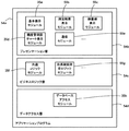
図9は、本発明の実施の形態1に係る血球分析装置2a,2b用のアプリケーションプログラム34aの構成を示す模式図である。アプリケーションプログラム34aは、プレゼンテーション層34bと、ビジネスロジック層34cと、データアクセス層34dとを有する3階層アーキテクチャとなっている。プレゼンテーション層34bは、アプリケーションプログラム34aにおけるユーザインタフェース部及び通信部に相当する階層であり、かかるプレゼンテーション層34bには、当該アプリケーションプログラム34aのウィンドウにおける基本的なパーツの表示を実行するための基本表示モジュール35a、血球分析装置2a,2bによる測定結果を画像表示部32に表示するための測定結果表示モジュール35b、検体が異常であること、又は異常の疑いがあることを示すIPメッセージを表示するためのIPメッセージ表示モジュール35c、精度管理画面を表示するための精度管理図チャート表示モジュール35d、及び血球分析装置2a,2bと通信するための通信モジュール35e等が属している。   FIG. 9 is a schematic diagram showing the configuration of the application program 34a for the blood cell analyzers 2a and 2b according to Embodiment 1 of the present invention. The application program 34a has a three-layer architecture having a presentation layer 34b, a business logic layer 34c, and a data access layer 34d. The presentation layer 34b is a hierarchy corresponding to a user interface unit and a communication unit in the application program 34a. The presentation layer 34b has a basic display module for executing display of basic parts in the window of the application program 34a. 35a, a measurement result display module 35b for displaying the measurement results by the blood cell analyzers 2a, 2b on the image display unit 32, for displaying an IP message indicating that the sample is abnormal or suspected of being abnormal The IP message display module 35c, the quality control chart display module 35d for displaying the quality control screen, the communication module 35e for communicating with the blood cell analyzers 2a and 2b, and the like belong.

また、ビジネスロジック層34cは、アプリケーションプログラム34aにおけるデータの処理、加工部に相当する階層であり、かかるビジネスロジック層34cには、データの単位換算を行う単位換算モジュール、精度管理用グラフを表示するためのデータを作成する精度管理グラフ表示用データ作成モジュール等を含む各機種共通の共通ロジックモジュール35f、及び血球分析装置固有のデータ処理を実行するための血球分析ロジックモジュール35g等が属している。   The business logic layer 34c is a hierarchy corresponding to the data processing and processing unit in the application program 34a, and the business logic layer 34c displays a unit conversion module for performing data unit conversion and a quality control graph. A common logic module 35f common to all models including a quality control graph display data creation module for creating data for the purpose, a blood cell analysis logic module 35g for executing data processing unique to the blood cell analyzer, and the like belong.

また、データアクセス層34dは、アプリケーションプログラム34aにおけるデータアクセス部に相当する階層であり、かかるデータアクセス層34dには、後述するデータベースDB21,DB22にアクセスするためのデータベースアクセスモジュール35hが属している。これらのプログラムモジュール35a〜35hは、アプリケーションプログラムのコンポーネントであり、実行形式ファイル又はダイナミックリンクライブラリに含まれている。また、ここでは、アプリケーションプログラム34aを構成するプログラムモジュールとして、上記のプログラムモジュール35a〜35hのみを記載しているが、これは説明を簡略化するために代表的なプログラムモジュールのみを示したものであって、実際にはこれら以外のプログラムモジュールも存在する。   The data access layer 34d is a hierarchy corresponding to a data access unit in the application program 34a, and a database access module 35h for accessing databases DB21 and DB22 described later belongs to the data access layer 34d. These program modules 35a to 35h are components of an application program, and are included in an executable file or a dynamic link library. Here, only the program modules 35a to 35h are described as the program modules constituting the application program 34a. However, for the sake of simplicity, only the representative program modules are shown. Actually, there are other program modules.

ここで、基本表示モジュール35a、精度管理図チャート表示モジュール35d、共通ロジックモジュール35f、及びデータベースアクセスモジュール35hは、血液凝固測定装置用のアプリケーションプログラムと共用のプログラムモジュール(以下、共通モジュールという)であり、これに対して、測定結果表示モジュール35b、IPメッセージ表示モジュール35c、通信モジュール35e、及び血球分析ロジックモジュール35gは、血球分析装置用のアプリケーションプログラム特有のプログラムモジュール(以下、機種依存モジュールという)である。図10は、ハードディスク31dにおける共通モジュールおよび機種依存モジュールの格納状態を示す模式図である。図10に示すように、基本表示モジュール35a、精度管理図チャート表示モジュール35d、共通ロジックモジュール35f、及びデータベースアクセスモジュール35hは、一つのダイナミックリンクライブラリ35iに格納されている。また、測定結果表示モジュール35b、IPメッセージ表示モジュール35c、通信モジュール35e、及び血球分析ロジックモジュール35gは、もう一つのダイナミックリンクライブラリ35jに格納されている。即ち、共通モジュールと機種依存モジュールとは別々のダイナミックリンクライブラリ35i,35jに格納され、これらのダイナミックリンクライブラリ35i,35jがハードディスク31dに保存されている。このように共通モジュールと機種依存モジュールとが別々のファイル(ダイナミックリンクライブラリ)に格納されているので、共通モジュールについてはコンパイル、リンクの処理を行わずにバイナリデータであるダイナミックリンクライブラリの形式のまま他のアプリケーションプログラムに利用することができ、利便性、開発効率が向上する。なお、共通モジュールは、本実施の形態で説明したように一つのダイナミックリンクライブラリ35iに格納されていてもよいが、複数のダイナミックリンクライブラリに分割して格納されていてもよい。同様に、機種依存モジュールは、本実施の形態で説明したように一つのダイナミックリンクライブラリ35jに格納されていてもよいが、複数のダイナミックリンクライブラリに分割して格納されていてもよい。   Here, the basic display module 35a, the quality control chart display module 35d, the common logic module 35f, and the database access module 35h are program modules that are shared with the application program for the blood coagulation measurement apparatus (hereinafter referred to as a common module). On the other hand, the measurement result display module 35b, the IP message display module 35c, the communication module 35e, and the blood cell analysis logic module 35g are program modules specific to application programs for blood cell analyzers (hereinafter referred to as model-dependent modules). is there. FIG. 10 is a schematic diagram showing a storage state of the common module and the model-dependent module in the hard disk 31d. As shown in FIG. 10, the basic display module 35a, the quality control chart display module 35d, the common logic module 35f, and the database access module 35h are stored in one dynamic link library 35i. The measurement result display module 35b, the IP message display module 35c, the communication module 35e, and the blood cell analysis logic module 35g are stored in another dynamic link library 35j. That is, the common module and the model-dependent module are stored in separate dynamic link libraries 35i and 35j, and these dynamic link libraries 35i and 35j are stored in the hard disk 31d. In this way, the common module and the model-dependent module are stored in separate files (dynamic link library), so the common module remains in the format of the dynamic link library that is binary data without compiling and linking. It can be used for other application programs, improving convenience and development efficiency. The common module may be stored in one dynamic link library 35i as described in the present embodiment, but may be divided and stored in a plurality of dynamic link libraries. Similarly, the model-dependent module may be stored in one dynamic link library 35j as described in the present embodiment, but may be divided and stored in a plurality of dynamic link libraries.

また、上述したようにアプリケーションプログラム34aは、プレゼンテーション層34b、ビジネスロジック層34c、およびデータアクセス層34dによって3階層に構成されており、プレゼンテーション層34bは、各測定装置によって異なるプログラムモジュールが多く属し、ビジネスロジック層34cは、測定原理が同一であって種類の異なる測定装置(例えば、血球分析装置の上位機種および下位機種)では共用するが、測定原理の異なる測定装置(例えば、血球分析装置および血液凝固測定装置)では共用することができないプログラムモジュールが多く属し、また、データアクセス層34dは、測定原理の異同を問わず、多種類の測定装置間で共用するプログラムモジュールが多く属するようになっている。このように、かかる階層はアプリケーションプログラムの部品の共用化のレベルに応じて分かれており、プログラムモジュールが共用化レベルで切り分けられているため、多機種間で効率的にプログラムモジュールを共用することができ、多機種のアプリケーションプログラムの開発をより一層効率化することが可能となる。   As described above, the application program 34a is configured in three layers by the presentation layer 34b, the business logic layer 34c, and the data access layer 34d, and the presentation layer 34b includes many program modules that differ depending on each measurement device. The business logic layer 34c has the same measurement principle and is shared by different types of measurement devices (for example, a higher-level model and a lower-level model of the blood cell analysis device), but a measurement device (for example, a blood cell analysis device and blood with different measurement principles). The coagulation measuring apparatus) has many program modules that cannot be shared, and the data access layer 34d has many program modules that are shared among various types of measuring apparatuses regardless of the measurement principle. Yes. In this way, such a hierarchy is divided according to the level of sharing of application program components, and since program modules are separated at the sharing level, it is possible to efficiently share program modules among multiple models. This makes it possible to further improve the efficiency of developing various types of application programs.

また、ハードディスク31dには、データベースDB21,DB22がインストールされている。データベースDB21は、検体番号及び血球分析装置2a,2bの測定結果データを互いに対応付けて格納するためのリレーショナルデータベースである。血球分析装置2a,2bの測定によって得られた測定結果データは、アプリケーションプログラム34aによってこのデータベースDB21に格納されるようになっている。また、アプリケーションプログラム34aは、データベースDB21にアクセスして、過去の測定結果データを読み出し、画像表示部32に表示させることが可能である。   Databases DB21 and DB22 are installed in the hard disk 31d. The database DB21 is a relational database for storing the sample number and the measurement result data of the blood cell analyzers 2a and 2b in association with each other. The measurement result data obtained by the measurement of the blood cell analyzers 2a and 2b is stored in this database DB21 by the application program 34a. Further, the application program 34 a can access the database DB 21, read past measurement result data, and display it on the image display unit 32.

データベースDB22は、アプリケーションプログラム34a及び血球分析装置2a,2bの設定値を格納するためのデータベースである。かかるデータベースDB22は、各種の設定データを互いに対応付けて格納するためのリレーショナルデータベースである。アプリケーションプログラム34aは、複数のユーザによって使用されるマルチユーザ型のソフトウェアであり、ユーザ毎にアプリケーションプログラム34aの機能の使用権限を設定することができたり、ユーザ毎に異なる表示形式を設定することができるようになっている。したがって、このようなユーザ毎の設定値等が、データベースDB22に保存され、アプリケーションプログラム34aは、起動時にデータベースDB22の設定データを読み出し、これによりユーザ毎の設定に合わせた動作を実現している。   The database DB22 is a database for storing setting values of the application program 34a and the blood cell analyzers 2a and 2b. The database DB 22 is a relational database for storing various setting data in association with each other. The application program 34a is multi-user type software that is used by a plurality of users, and the authority to use the functions of the application program 34a can be set for each user, or a different display format can be set for each user. It can be done. Accordingly, such setting values for each user are stored in the database DB 22, and the application program 34a reads the setting data in the database DB 22 at the time of activation, thereby realizing an operation according to the setting for each user.

アプリケーションプログラム34aは、起動時にデータベースDB22から設定データを読み出し、これらの設定データによってデータツリーTを構成する。図11及び図12は、データツリーTの一例を示す概念図である。データベースDB22は、アプリケーションプログラム34a及び血球分析装置2a,2bの設定データが格納されており、アプリケーションプログラム34aからは、設定データの読み出し、及び設定データの更新のためにアクセスされる。例えば、「項目“HGB”の表示単位は“g/dL”である。」という設定内容は、設定条件を示す第1データ“項目=HGB”と、設定項目と設定値とが互いに関連づけられた第2データ“表示単位=g/dL”とを含むデータセット(設定データ)で与えられる。また、「ユーザ名“Admin”はデータ変更権限を有する。」という設定内容は、設定条件を示す第1データ“ユーザ名=Admin”と、設定項目と設定値とが互いに関連づけられた第2データ“データ変更権限=有”とを含むデータセットで与えられ、「ユーザ名“User1”はデータ変更権限を有さない。」という設定内容は、第1データ“ユーザ名=User1”と、第2データ“データ変更権限=無”とを含むデータセットで与えられる。夫々のデータセットは、このように複数のデータ(第1データ、第2データ)を含んでおり、同一のデータセットに含まれるデータ郡は、互いに関連付けられてデータベースDB22に格納される。   The application program 34a reads the setting data from the database DB22 at the time of activation, and forms a data tree T with these setting data. 11 and 12 are conceptual diagrams illustrating an example of the data tree T. FIG. The database DB 22 stores setting data of the application program 34a and the blood cell analyzers 2a and 2b, and is accessed from the application program 34a for reading of setting data and updating of setting data. For example, the setting content “the display unit of the item“ HGB ”is“ g / dL ”” indicates that the first data “item = HGB” indicating the setting condition is associated with the setting item and the setting value. It is given by a data set (setting data) including the second data “display unit = g / dL”. In addition, the setting content “user name“ Admin ”has data change authority” includes the first data “user name = Admin” indicating the setting condition, and the second data in which the setting item and the setting value are associated with each other. Given with a data set including “data change authority = present”, the setting content “user name“ User1 ”does not have data change authority” includes the first data “user name = User1” and the second It is given in a data set including data “data change authority = no”. Each data set includes a plurality of data (first data and second data) as described above, and data groups included in the same data set are stored in the database DB 22 in association with each other.

ここで、アプリケーションプログラム34aによってデータベースDB22を使用する場合の動作について説明する。図13は、アプリケーションプログラム34aによる設定動作の流れを示すフローチャートである。ユーザがデータ処理装置3の画像表示部32の画面に表示されたアイコンをマウスでダブルクリックする等、アプリケーションプログラム34aの動作開始の指示をデータ処理装置3に入力した場合には、CPU31aは、この動作開始指示を受け付けて、アプリケーションプログラム34aを起動する(ステップS101)。次にCPU31aは、データベースDB22から設定データ(データセット)を読み出し(ステップS102)、かかる設定データを加工する(ステップS103)。上述したように、各設定データは、設定条件を示す第1データと、設定項目と設定値とが互いに関連づけられた第2データとを含んでいる。このステップS103の処理では、かかるデータセットを、「設定項目」、「設定条件」、及び「設定値」に分解する加工を行う。つまり、“項目=HGB”、“表示単位=g/dL”のデータセットは、「設定項目」としてのデータ“表示単位”と、「設定条件」としてのデータ“項目=HGB”と、「設定値」としてのデータ“g/dL”とに加工される。同様に、“ユーザ名=Admin”、“データ変更権限=有”のデータセットは、「設定項目」としてのデータ“データ変更権限”と、「設定条件」としてのデータ“ユーザ名=Admin”と、「設定値」としてのデータ“有”とに加工され、“ユーザ名=User1”、“データ変更権限=無”のデータセットは、「設定項目」としてのデータ“データ変更権限”と、「設定条件」としてのデータ“ユーザ名=User1”と、「設定値」としてのデータ“無”とに加工される。加工後のデータは、CPU31aによってRAM31cに構成されたハッシュテーブルにセットされ(ステップS104)、これによって図11に示すようなデータツリーT1,T2が構成される。アプリケーションプログラム34aのデータベースアクセスモジュール35hは、かかるデータツリーT1,T2にアクセスして、例えば、“表示単位”、“項目=HGB”、“g/dL”の順に探索して、「設定項目」が“表示単位”であり、「設定条件」が“項目=HGB”である設定値データ“g/dL”を取得することができる。こうして、アプリケーションプログラム34aの設定動作が完了する。   Here, the operation when the database DB22 is used by the application program 34a will be described. FIG. 13 is a flowchart showing the flow of setting operation by the application program 34a. When the user inputs an operation start instruction of the application program 34a to the data processing device 3, such as double-clicking an icon displayed on the screen of the image display unit 32 of the data processing device 3, the CPU 31a In response to the operation start instruction, the application program 34a is activated (step S101). Next, the CPU 31a reads setting data (data set) from the database DB22 (step S102), and processes the setting data (step S103). As described above, each setting data includes first data indicating a setting condition and second data in which setting items and setting values are associated with each other. In the process of step S103, the data set is decomposed into “setting items”, “setting conditions”, and “setting values”. That is, the data set of “item = HGB” and “display unit = g / dL” includes data “display unit” as “setting item”, data “item = HGB” as “setting condition”, “setting” Data “g / dL” as “value” is processed. Similarly, a data set of “user name = Admin” and “data change authority = present” has data “data change authority” as “setting item” and data “user name = Admin” as “setting condition”. , The data set “data” having “user name = User1” and “data change authority = no” is processed as “setting value”, “data change authority”, and “data change authority” Data “user name = User1” as “setting condition” and data “none” as “setting value” are processed. The processed data is set in the hash table configured in the RAM 31c by the CPU 31a (step S104), thereby configuring data trees T1 and T2 as shown in FIG. The database access module 35h of the application program 34a accesses the data trees T1 and T2 and searches, for example, “display unit”, “item = HGB”, “g / dL” in this order. It is possible to obtain set value data “g / dL” which is “display unit” and whose “setting condition” is “item = HGB”. Thus, the setting operation of the application program 34a is completed.

ここで、図11に示した例から、「ユーザ毎に各項目の表示単位を変更可能」とするようにアプリケーションプログラム34aの仕様を変更する場合について説明する。例えば、上記例から「ユーザ名“Admin”における表示項目“HGB”の表示単位は“g/dL”である。」という設定内容に夫々変更された場合、与えられるデータセットは、設定条件を示す第1データである“ユーザ名=Admin”及び“項目=HGB”と、設定項目と設定値とが互いに関連づけられた第2データである“表示単位=g/dL”とを含んでおり、「ユーザ名“User1”における表示項目“HGB”の表示単位は“g/L”である。」という設定内容に夫々変更された場合、与えられるデータセットは、第1データである“ユーザ名=User1”及び“項目=HGB”と、第2データである“表示単位=g/L”とを含んでいる。そして、アプリケーションプログラム34aが起動した場合には、“ユーザ名=Admin”、“項目=HGB”、“表示単位=g/dL”のデータセットは、「設定項目」としてのデータ“表示単位”と、「設定条件」としてのデータ“ユーザ名=Admin”及び“項目=HGB”と、「設定値」としてのデータ“g/dL”とに加工される。同様に、“ユーザ名=User1”、“項目=HGB”、“表示単位=g/L”のデータセットは、「設定項目」としてのデータ“表示単位”と、「設定条件」としてのデータ“ユーザ名=User1”及び“項目=HGB”と、「設定値」としてのデータ“g/L”とに加工される。加工後のデータは、ハッシュテーブルにセットされ、これによって図12に示すようなデータツリーT11,T2が構成されることとなる。このように、ルートノードを「設定項目」とし、中間ノードを「設定条件」とし、リーフノードを「設定値」としたツリーに設定データを展開することとしたので、「設定項目」毎に独立したデータツリーが構成されることとなる。例えば、「設定項目」が“表示単位”のデータツリーT11と、「設定項目」が“データ変更権限”のデータツリーT2は別々に構成されることとなる。したがって、上述したようにアプリケーションプログラム34aの“表示単位”の設定仕様が変更された場合には、「設定項目」が“表示単位”のデータツリーT1はデータツリーT11へと変更されるが、その変更は“データ変更権限”のデータツリーT2には影響を及ぼさない(図12参照)。したがって、アプリケーションプログラム34aのバージョンアップ等により、一部の設定仕様を変更する場合には、アプリケーションプログラム34aのうち、変更されるデータツリーに関する部分のみを変更すればよく、開発工数を抑制することができる。また、かかる変更後のデータツリーT11は、データベースの構造自体は変更されないので、データベースアクセスモジュール35hを何ら変更しなくても、アプリケーションプログラム34aからアクセスすることが可能である。したがって、このように、設定値の仕様を変更した場合にも、アプリケーションプログラム34aの変更を最小限に抑えることができ、利便性、開発効率が向上する。   Here, a case where the specification of the application program 34a is changed so that “the display unit of each item can be changed for each user” will be described from the example illustrated in FIG. For example, from the above example, when the setting content is changed to “g / dL” for the display item “HGB” in the user name “Admin”, the given data set indicates the setting condition. “User name = Admin” and “item = HGB” as the first data, and “display unit = g / dL” as the second data in which the setting item and the setting value are associated with each other. When the display item “HGB” in the user name “User1” is changed to the setting content “g / L”, the given data set is “username = User1”. And “item = HGB” and “display unit = g / L” as the second data. When the application program 34a is activated, the data set of “user name = Admin”, “item = HGB”, “display unit = g / dL” is the data “display unit” as “setting item”. , Data “user name = Admin” and “item = HGB” as “setting conditions” and data “g / dL” as “setting values” are processed. Similarly, a data set of “user name = User1”, “item = HGB”, “display unit = g / L” includes data “display unit” as “setting item” and data “data” as “setting condition”. The user name = User1 ”and“ item = HGB ”and the data“ g / L ”as“ setting value ”are processed. The processed data is set in a hash table, whereby data trees T11 and T2 as shown in FIG. 12 are configured. In this way, the setting data is expanded in a tree with the root node as the “setting item”, the intermediate node as the “setting condition”, and the leaf node as the “setting value”. A data tree is constructed. For example, the data tree T11 whose “setting item” is “display unit” and the data tree T2 whose “setting item” is “data change authority” are configured separately. Therefore, when the setting specification of the “display unit” of the application program 34a is changed as described above, the data tree T1 whose “setting item” is “display unit” is changed to the data tree T11. The change does not affect the data tree T2 of “data change authority” (see FIG. 12). Therefore, when changing some setting specifications due to version upgrade of the application program 34a, etc., it is only necessary to change only the part related to the data tree to be changed in the application program 34a, thereby reducing the development man-hours. it can. Further, since the database structure itself is not changed, the data tree T11 after the change can be accessed from the application program 34a without changing the database access module 35h. Therefore, even when the setting value specification is changed as described above, the change of the application program 34a can be minimized, and convenience and development efficiency are improved.

入出力インタフェース31fは、例えばUSB,IEEE1394,RS-232C等のシリアルインタフェース、SCSI,IDE,IEEE1284等のパラレルインタフェース、およびD/A変換器、A/D変換器等からなるアナログインタフェース等から構成されている。入出力インタフェース31fには、キーボードおよびマウスからなる入力部33が接続されており、ユーザが当該入力部33を使用することにより、コンピュータ3aにデータを入力することが可能である。   The input / output interface 31f includes, for example, a serial interface such as USB, IEEE1394, and RS-232C, a parallel interface such as SCSI, IDE, and IEEE1284, and an analog interface including a D / A converter and an A / D converter. ing. An input unit 33 composed of a keyboard and a mouse is connected to the input / output interface 31f, and the user can input data to the computer 3a by using the input unit 33.

通信インタフェース31gは、例えばEthernet(登録商標)インタフェースであり、データ処理装置3は、当該通信インタフェース31gにより、所定の通信プロトコルを使用して通信ネットワークNWに接続された血球分析装置2a,2b、血液凝固測定装置4a,4b、データ処理装置5,6、及びデータベースサーバ7の夫々との間でデータの送受信が可能である。   The communication interface 31g is an Ethernet (registered trademark) interface, for example. Data can be transmitted and received between the coagulation measuring devices 4a and 4b, the data processing devices 5 and 6, and the database server 7.

画像出力インタフェース31hは、LCDまたはCRT等で構成された画像表示部32に接続されており、CPU31aから与えられた画像データに応じた映像信号を画像表示部32に出力するようになっている。画像表示部32は、入力された映像信号にしたがって、画像(画面)を表示する。   The image output interface 31h is connected to an image display unit 32 constituted by an LCD, a CRT or the like, and outputs a video signal corresponding to the image data given from the CPU 31a to the image display unit 32. The image display unit 32 displays an image (screen) according to the input video signal.

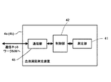
次に、血液凝固測定装置4a,4bの構成について説明する。図14は、血液凝固測定装置4a(4b)の構成を示すブロック図である。血液凝固測定装置4a(4b)は、測定部41と、制御部42と、通信部45とを主要な構成要素として構成されている。制御部42は、CPU,ROM,RAM等から構成されており、血液凝固測定装置4aの各種構成要素の動作制御を行うようになっている。通信部45は、例えばEthernet(登録商標)インタフェースであり、データ処理装置3,5,6との間でデータの送受信を行うことが可能である。   Next, the configuration of the blood coagulation measuring devices 4a and 4b will be described. FIG. 14 is a block diagram showing a configuration of the blood coagulation measuring apparatus 4a (4b). The blood coagulation measurement apparatus 4a (4b) is configured with a measurement unit 41, a control unit 42, and a communication unit 45 as main components. The control unit 42 includes a CPU, a ROM, a RAM, and the like, and performs operation control of various components of the blood coagulation measuring device 4a. The communication unit 45 is an Ethernet (registered trademark) interface, for example, and can transmit and receive data to and from the data processing devices 3, 5, and 6.

測定部41は、発光ダイオード41aと、ハロゲンランプ41bと、光学フィルタ41cと、光ファイバ41dと、フォトダイオード41e,41fとを有しており(図15及び図16参照)、また図示しないヒータを有している。かかる測定部41は、生物活性法を利用して血液の凝固時間を測定することが可能であり、また、合成基質法を利用して、血漿に特定の試薬及び発色性合成基質を添加したときの吸光度変化量を測定することが可能であり、また、免疫比濁法を利用して、血漿又は血清に安定化試薬及び抗体感作試薬を添加したときの吸光度変化量を測定することが可能であるように構成されている。   The measuring unit 41 includes a light emitting diode 41a, a halogen lamp 41b, an optical filter 41c, an optical fiber 41d, and photodiodes 41e and 41f (see FIGS. 15 and 16), and a heater (not shown). Have. The measuring unit 41 can measure the blood coagulation time using a biological activity method, and when a specific reagent and a chromogenic synthetic substrate are added to plasma using a synthetic substrate method. It is possible to measure the amount of change in absorbance when a stabilizing reagent and an antibody sensitizing reagent are added to plasma or serum using an immunoturbidimetric method. It is comprised so that.

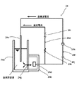
図15は、生物活性法による測定原理を説明するための模式図である。図15に示すように、測定部41では、発光ダイオード41aが試料を収容するキュベット41gへ向けて発光するように配置されている。また、キュベット41gの側方には、受光面がキュベット41gへと向けられてフォトダイオード41eが配置されており、このフォトダイオード41eの受光光軸方向は、発光ダイオード41aの発光光軸に対して水平方向に約90度をなしている。発光ダイオード41aは、約660nmの波長の光を発するようになっている。定量された血漿がキュベット41gに収容され、一定時間ヒータによって加温された後、凝固試薬が添加される。この後、発光ダイオード41aから試料へ向けて光が照射され、試料による散乱光がフォトダイオード41eで受光される。この受光量は、試料の濁度を表しており、試薬を添加した直後の試料は散乱光が弱く(濁度が低く)、受光量の変化はほとんどないが、反応が進むにつれて試料中にフィブリン塊が形成され始め、それに伴って試料が白濁して散乱光が急速に増加する。凝固反応が終了すると散乱光の増加はなくなり、一定の受光レベルになる。フォトダイオード41eは、受光量に応じた電気信号を出力するようになっており、この電気信号が制御部42に与えられるようになっている。制御部42では、この受光量データから試料の凝固時間を算出するようになっており、また、この凝固時間から特定の血液成分の濃度又は活性パーセントを演算することができるようになっている。   FIG. 15 is a schematic diagram for explaining the measurement principle by the biological activity method. As shown in FIG. 15, in the measurement part 41, the light emitting diode 41a is arrange | positioned so that it may light-emit toward the cuvette 41g which accommodates a sample. Further, a photodiode 41e is disposed on the side of the cuvette 41g with the light receiving surface directed toward the cuvette 41g. The light receiving optical axis direction of the photodiode 41e is relative to the light emitting optical axis of the light emitting diode 41a. It is approximately 90 degrees horizontally. The light emitting diode 41a emits light having a wavelength of about 660 nm. The quantified plasma is stored in 41 g of cuvette and heated by a heater for a certain time, and then a coagulation reagent is added. Thereafter, light is emitted from the light emitting diode 41a toward the sample, and scattered light from the sample is received by the photodiode 41e. The amount of light received represents the turbidity of the sample. The sample immediately after the addition of the reagent has weak scattered light (low turbidity) and there is almost no change in the amount of received light. However, as the reaction proceeds, fibrin is present in the sample. A lump starts to form, and as a result, the sample becomes cloudy and the scattered light rapidly increases. When the coagulation reaction is completed, the scattered light does not increase and the light reception level is constant. The photodiode 41e is configured to output an electrical signal corresponding to the amount of received light, and this electrical signal is supplied to the control unit 42. The control unit 42 calculates the coagulation time of the sample from the received light amount data, and can calculate the concentration or activity percentage of a specific blood component from the coagulation time.

図16は、合成基質法及び免疫比濁法による測定原理を説明するための模式図である。図16に示すように、測定部41では、ハロゲンランプ41bがキュベット41gへ向けて発光するように配置されている。ハロゲンランプ41bとキュベット41gとの間には、光学フィルタ41cと光ファイバ41dとが配されており、ハロゲンランプ41bから照射された光が光学フィルタ41cによって800nm、575nm、405nmの3つの波長に分光され、分光された光が光ファイバ41dを通じて試料に照射されるようになっている。キュベット41gに対向するようにフォトダイオード41fが配置されており、試料を透過した光はこのフォトダイオード41fに到達し、フォトダイオード41fが受光を電気信号へ変換して制御部42へ出力するようになっている。制御部42は、この受光量データから吸光度変化量を算出し、また、前記吸光度変化量、及び吸光度変化量と特定の血液成分の濃度又は活性パーセントとの関係を示す検量線に基づいて、特定の血液成分の濃度又は活性パーセントを演算することができるようになっている。ATIII(アンチトロンビンIII)、α2PI(α2−アンチプラスミン)等を合成基質法により測定する場合には、血漿を一定時間ヒータにより加温した後に、発色性合成基質を添加し、405nmの光を照射して、このときの吸光度変化を測定する。また、FDP(フィブリン分解産物)、D−Dダイマー等を免疫比濁法により測定する場合には、試料(血漿又は血清)を一定時間ヒータにより加温した後に、安定化試薬、抗体感作試薬を添加し、575nm又は800nmの光を照射して、このときの吸光度変化を測定する。   FIG. 16 is a schematic diagram for explaining the measurement principle by the synthetic substrate method and the immunoturbidimetric method. As shown in FIG. 16, in the measurement unit 41, the halogen lamp 41b is arranged to emit light toward the cuvette 41g. An optical filter 41c and an optical fiber 41d are disposed between the halogen lamp 41b and the cuvette 41g, and light emitted from the halogen lamp 41b is split into three wavelengths of 800 nm, 575 nm, and 405 nm by the optical filter 41c. Then, the sampled light is irradiated onto the sample through the optical fiber 41d. A photodiode 41f is arranged so as to face the cuvette 41g, and the light transmitted through the sample reaches the photodiode 41f, and the photodiode 41f converts the received light into an electric signal and outputs it to the control unit 42. It has become. The control unit 42 calculates the absorbance change amount from the received light amount data, and specifies the absorbance change amount and the calibration curve indicating the relationship between the absorbance change amount and the concentration or activity percentage of a specific blood component. The blood component concentration or activity percentage can be calculated. When measuring ATIII (antithrombin III), α2PI (α2-antiplasmin), etc. by the synthetic substrate method, plasma is heated with a heater for a certain period of time, then a chromogenic synthetic substrate is added and irradiated with light at 405 nm. Then, the absorbance change at this time is measured. When measuring FDP (fibrin degradation product), DD dimer, etc. by immunoturbidimetry, a sample (plasma or serum) is heated with a heater for a certain period of time, and then a stabilizing reagent, an antibody sensitizing reagent Is added, irradiated with light of 575 nm or 800 nm, and the change in absorbance at this time is measured.

次に、データ処理装置5の構成について説明する。図17は、本発明の実施の形態1に係る血液凝固測定装置4a,4b用のデータ処理装置5の構成を示すブロック図である。図17に示すように、データ処理装置5は、本体51と、画像表示部52と、入力部53とから主として構成されたコンピュータ5aによって構成されている。本体51は、CPU51aと、ROM51bと、RAM51cと、ハードディスク51dと、読出装置51eと、入出力インタフェース51fと、通信インタフェース51gと、画像出力インタフェース51hとから主として構成されており、CPU51a、ROM51b、RAM51c、ハードディスク51d、読出装置51e、入出力インタフェース51f、通信インタフェース51g、および画像出力インタフェース51hは、バス51iによって接続されている。CPU51a、ROM51b、RAM51c、読出装置51e、入出力インタフェース51f、通信インタフェース51g、及び画像出力インタフェース51hの構成は、上述したCPU31a、ROM31b、RAM31c、読出装置31e、入出力インタフェース31f、通信インタフェース31g、及び画像出力インタフェース31hの構成と同様であるので、その説明を省略する。   Next, the configuration of the data processing device 5 will be described. FIG. 17 is a block diagram showing a configuration of the data processing device 5 for the blood coagulation measuring devices 4a and 4b according to the first embodiment of the present invention. As shown in FIG. 17, the data processing device 5 is configured by a computer 5 a mainly composed of a main body 51, an image display unit 52, and an input unit 53. The main body 51 mainly includes a CPU 51a, a ROM 51b, a RAM 51c, a hard disk 51d, a reading device 51e, an input / output interface 51f, a communication interface 51g, and an image output interface 51h. The CPU 51a, ROM 51b, and RAM 51c. The hard disk 51d, reading device 51e, input / output interface 51f, communication interface 51g, and image output interface 51h are connected by a bus 51i. The configurations of the CPU 51a, ROM 51b, RAM 51c, reading device 51e, input / output interface 51f, communication interface 51g, and image output interface 51h are as described above for the CPU 31a, ROM 31b, RAM 31c, reading device 31e, input / output interface 31f, communication interface 31g, and Since the configuration is the same as that of the image output interface 31h, the description thereof is omitted.

読出装置51eによってデータの読み出しが可能な可搬型記録媒体54には、コンピュータを本発明に係る測定装置用データ処理装置として機能させるためのアプリケーションプログラム54aが格納されており、コンピュータ5aが当該可搬型記録媒体54から本発明に係るアプリケーションプログラム54aを読み出し、当該アプリケーションプログラム54aをハードディスク51dにインストールすることが可能である。なお、前述したアプリケーションプログラム34aと同様に、アプリケーションプログラム54aは、可搬型記録媒体54によって提供されるのみならず、電気通信回線(有線、無線を問わない)によってコンピュータ5aと通信可能に接続された外部の機器から前記電気通信回線を通じて提供することも可能である。   The portable recording medium 54 from which data can be read by the reading device 51e stores an application program 54a for causing the computer to function as the data processing device for the measuring device according to the present invention. It is possible to read the application program 54a according to the present invention from the recording medium 54 and install the application program 54a in the hard disk 51d. Similar to the application program 34a described above, the application program 54a is not only provided by the portable recording medium 54 but also connected to the computer 5a through an electric communication line (whether wired or wireless). It is also possible to provide from an external device through the telecommunication line.

ハードディスク51dには、例えば米マイクロソフト社が製造販売するWindows(登録商標)等のグラフィカルユーザインタフェース環境を提供するオペレーティングシステム、及びアプリケーションプログラム54aがインストールされている。以下の説明においては、本実施の形態1に係るアプリケーションプログラム54aは前記オペレーティングシステム上で動作するものとしている。   An operating system that provides a graphical user interface environment such as Windows (registered trademark) manufactured and sold by US Microsoft Corporation and an application program 54a are installed on the hard disk 51d. In the following description, it is assumed that the application program 54a according to the first embodiment operates on the operating system.

図18は、本発明の実施の形態1に係る血液凝固測定装置4a,4b用のアプリケーションプログラム54aの構成を示す模式図である。アプリケーションプログラム54aは、アプリケーションプログラム34aと同様に、プレゼンテーション層54bと、ビジネスロジック層54cと、データアクセス層54dとを有する3階層アーキテクチャとなっている。プレゼンテーション層54bは、アプリケーションプログラム54aにおけるユーザインタフェース部及び通信部に相当する階層であり、かかるプレゼンテーション層54bには、当該アプリケーションプログラム54aのウィンドウにおける基本的なパーツの表示を実行するための基本表示モジュール35a、血液凝固測定装置4a,4bによる測定結果を画像表示部52に表示するための測定結果表示モジュール55b、測定結果の演算に用いられる検量線を表示するための検量線表示モジュール55c、精度管理画面を表示するための精度管理図チャート表示モジュール35d、及び血液凝固測定装置4a,4bと通信するための通信モジュール55e等が属している。   FIG. 18 is a schematic diagram showing the configuration of the application program 54a for the blood coagulation measuring apparatuses 4a and 4b according to the first embodiment of the present invention. Similar to the application program 34a, the application program 54a has a three-layer architecture having a presentation layer 54b, a business logic layer 54c, and a data access layer 54d. The presentation layer 54b is a hierarchy corresponding to a user interface unit and a communication unit in the application program 54a. The presentation layer 54b has a basic display module for executing display of basic parts in the window of the application program 54a. 35a, a measurement result display module 55b for displaying the measurement results by the blood coagulation measuring devices 4a and 4b on the image display unit 52, a calibration curve display module 55c for displaying a calibration curve used for calculation of the measurement results, and accuracy control A quality control chart display module 35d for displaying a screen, a communication module 55e for communicating with the blood coagulation measuring devices 4a and 4b, and the like belong to this.

また、ビジネスロジック層54cは、アプリケーションプログラム54aにおけるデータの処理、加工部に相当する階層であり、かかるビジネスロジック層54cには、データの単位換算を行う単位換算モジュール、精度管理用グラフを表示するためのデータを作成する精度管理グラフ表示用データ作成モジュール等を含む各機種共通の共通ロジックモジュール35f、及び血液凝固測定装置固有のデータ処理を実行するための血液凝固測定ロジックモジュール55g等が属している。   The business logic layer 54c is a hierarchy corresponding to the data processing and processing unit in the application program 54a. The business logic layer 54c displays a unit conversion module for performing data unit conversion and a quality control graph. A common logic module 35f common to all models, including a data creation module for accuracy control graph display for creating data for the purpose, and a blood coagulation measurement logic module 55g for executing data processing unique to the blood coagulation measurement apparatus Yes.

また、データアクセス層54dは、アプリケーションプログラム54aにおけるデータアクセス部に相当する階層であり、かかるデータアクセス層54dには、後述するデータベースDB41,DB42にアクセスするためのデータベースアクセスモジュール35hが属している。これらのプログラムモジュール35a,35d,35f,35h,55b,55c,55e,55gは、アプリケーションプログラムのコンポーネントであり、実行形式ファイル又はダイナミックリンクライブラリに含まれている。また、ここでは、アプリケーションプログラム54aを構成するプログラムモジュールとして、上記のプログラムモジュール35a,35d,35f,35h,55b,55c,55e,55gのみを記載しているが、これは説明を簡略化するために代表的なプログラムモジュールのみを示したものであって、実際にはこれら以外のプログラムモジュールも存在する。   The data access layer 54d is a layer corresponding to a data access unit in the application program 54a, and a database access module 35h for accessing databases DB41 and DB42 described later belongs to the data access layer 54d. These program modules 35a, 35d, 35f, 35h, 55b, 55c, 55e, and 55g are components of the application program and are included in the executable file or the dynamic link library. Here, only the above-described program modules 35a, 35d, 35f, 35h, 55b, 55c, 55e, and 55g are described as program modules constituting the application program 54a, but this is for the sake of simplifying the explanation. Only representative program modules are shown, and there are actually other program modules.

上述したように、基本表示モジュール35a、精度管理図チャート表示モジュール35d、共通ロジックモジュール35f、及びデータベースアクセスモジュール35hは、血球分析装置用のアプリケーションプログラムと共用の共通モジュールであり、これに対して、測定結果表示モジュール55b、検量線表示モジュール55c、通信モジュール55e、及び血液凝固測定ロジックモジュール55gは、血液凝固測定装置用のアプリケーションプログラム特有の機種依存モジュールである。   As described above, the basic display module 35a, the quality control chart display module 35d, the common logic module 35f, and the database access module 35h are common modules that are shared with the application program for the blood cell analyzer. The measurement result display module 55b, the calibration curve display module 55c, the communication module 55e, and the blood coagulation measurement logic module 55g are model-dependent modules unique to application programs for the blood coagulation measurement apparatus.

また、上述したアプリケーションプログラム34aと同様に、アプリケーションプログラム54aの共通モジュールと機種依存モジュールとは別々のダイナミックリンクライブラリに格納されている。また、アプリケーションプログラム54aの共通モジュールは、1つのダイナミックリンクライブラリ35iに格納されており、機種依存モジュールは、他の1つのダイナミックリンクライブラリに格納されている(図示せず)。また、共通モジュールのダイナミックリンクライブラリは、血球分析装置用のアプリケーションプログラム34aのダイナミックリンクライブラリ35iと同一のものである。これにより、ダイナミックリンクライブラリ35iは、新たに開発する必要はなく、アプリケーションプログラム34aのダイナミックリンクライブラリ35iのコピーをハードディスク51d内の所定の格納場所(ディレクトリ)に格納するだけで、アプリケーションプログラム54aに流用することができる。なお、共通モジュールは、一つのダイナミックリンクライブラリに格納されていてもよいし、複数のダイナミックリンクライブラリに分割して格納されていてもよく、また機種依存モジュールは、一つのダイナミックリンクライブラリに格納されていてもよいし、複数のダイナミックリンクライブラリに分割して格納されていてもよい。   Similarly to the application program 34a described above, the common module and the model-dependent module of the application program 54a are stored in separate dynamic link libraries. The common module of the application program 54a is stored in one dynamic link library 35i, and the model-dependent module is stored in another dynamic link library (not shown). The dynamic link library of the common module is the same as the dynamic link library 35i of the application program 34a for the blood cell analyzer. As a result, the dynamic link library 35i does not need to be newly developed, and can be used for the application program 54a simply by storing a copy of the dynamic link library 35i of the application program 34a in a predetermined storage location (directory) in the hard disk 51d. can do. The common module may be stored in one dynamic link library or may be divided into a plurality of dynamic link libraries, and the model-dependent module is stored in one dynamic link library. Or may be divided and stored in a plurality of dynamic link libraries.

また、ハードディスク51dには、データベースDB41,DB42がインストールされている。データベースDB41は、検体番号及び血液凝固測定装置4a,4bの測定結果データを互いに対応付けて格納するためのリレーショナルデータベースである。このデータベースDB41は、データベースDB21と同様のスキーマで構成されており、血液凝固測定装置4a,4bの測定によって得られた測定結果データは、アプリケーションプログラム54aによってこのデータベースDB41に格納されるようになっている。また、アプリケーションプログラム54aは、データベースDB41にアクセスして、過去の測定結果データを読み出し、画像表示部52に表示させることが可能である。   Databases DB41 and DB42 are installed in the hard disk 51d. The database DB 41 is a relational database for storing the sample number and the measurement result data of the blood coagulation measuring devices 4a and 4b in association with each other. The database DB41 is configured with the same schema as the database DB21, and the measurement result data obtained by the measurement of the blood coagulation measuring apparatuses 4a and 4b is stored in the database DB41 by the application program 54a. Yes. Further, the application program 54 a can access the database DB 41, read past measurement result data, and display the data on the image display unit 52.

データベースDB42は、アプリケーションプログラム54aの設定データを格納するためのリレーショナルデータベースである。このデータベースDB42に格納された設定データは、アプリケーションプログラム54aの動作時にCPU51aによって読み出され、データベースDB22の場合と同様に「設定項目」、「設定条件」、及び「設定値」のデータに加工される。そして、加工された各データによって設定用のデータツリーが構成され、このデータツリーによって表現された設定内容がアプリケーションプログラム54aの動作時に反映される。かかるデータツリーの構造は、アプリケーションプログラム34aによって使用されるデータツリーt1,t2,t11の構造と同様であるので、その説明を省略する。   The database DB42 is a relational database for storing setting data of the application program 54a. The setting data stored in the database DB 42 is read by the CPU 51a during the operation of the application program 54a, and is processed into “setting item”, “setting condition”, and “setting value” data as in the case of the database DB 22. The A data tree for setting is constituted by each processed data, and setting contents expressed by the data tree are reflected when the application program 54a is operated. Since the structure of the data tree is the same as that of the data trees t1, t2, and t11 used by the application program 34a, the description thereof is omitted.

次に、データ処理装置6の構成について説明する。図19は、本発明の実施の形態1に係る血球分析装置2a,2b及び血液凝固測定装置4a,4bの測定結果参照用のデータ処理装置6の構成を示すブロック図である。図19に示すように、データ処理装置6は、本体61と、画像表示部62と、入力部63とから主として構成されたコンピュータ6aによって構成されている。本体61は、CPU61aと、ROM61bと、RAM61cと、ハードディスク61dと、読出装置61eと、入出力インタフェース61fと、通信インタフェース61gと、画像出力インタフェース61hとから主として構成されており、CPU61a、ROM61b、RAM61c、ハードディスク61d、読出装置61e、入出力インタフェース61f、通信インタフェース61g、および画像出力インタフェース61hは、バス61iによって接続されている。CPU61a、ROM61b、RAM61c、読出装置61e、入出力インタフェース61f、通信インタフェース61g、及び画像出力インタフェース61hの構成は、上述したCPU31a、ROM31b、RAM31c、読出装置31e、入出力インタフェース31f、通信インタフェース31g、及び画像出力インタフェース31hの構成と同様であるので、その説明を省略する。   Next, the configuration of the data processing device 6 will be described. FIG. 19 is a block diagram showing the configuration of the data processing apparatus 6 for referring to the measurement results of the blood cell analyzers 2a and 2b and the blood coagulation measuring apparatuses 4a and 4b according to Embodiment 1 of the present invention. As shown in FIG. 19, the data processing device 6 is configured by a computer 6 a mainly including a main body 61, an image display unit 62, and an input unit 63. The main body 61 mainly includes a CPU 61a, a ROM 61b, a RAM 61c, a hard disk 61d, a reading device 61e, an input / output interface 61f, a communication interface 61g, and an image output interface 61h. The CPU 61a, ROM 61b, and RAM 61c. The hard disk 61d, the reading device 61e, the input / output interface 61f, the communication interface 61g, and the image output interface 61h are connected by a bus 61i. The configurations of the CPU 61a, ROM 61b, RAM 61c, reading device 61e, input / output interface 61f, communication interface 61g, and image output interface 61h are as described above for the CPU 31a, ROM 31b, RAM 31c, reading device 31e, input / output interface 31f, communication interface 31g, and Since the configuration is the same as that of the image output interface 31h, the description thereof is omitted.

読出装置61eによってデータの読み出しが可能な可搬型記録媒体64には、コンピュータを本発明に係る測定装置用データ処理装置として機能させるためのアプリケーションプログラム64aが格納されており、コンピュータ6aが当該可搬型記録媒体64から本発明に係るアプリケーションプログラム64aを読み出し、当該アプリケーションプログラム64aをハードディスク61dにインストールすることが可能である。なお、前述したアプリケーションプログラム34aと同様に、アプリケーションプログラム64aは、可搬型記録媒体64によって提供されるのみならず、電気通信回線(有線、無線を問わない)によってコンピュータ6aと通信可能に接続された外部の機器から前記電気通信回線を通じて提供することも可能である。   A portable recording medium 64 from which data can be read by the reading device 61e stores an application program 64a for causing the computer to function as the data processing device for the measuring device according to the present invention. It is possible to read the application program 64a according to the present invention from the recording medium 64 and install the application program 64a in the hard disk 61d. Similar to the application program 34a described above, the application program 64a is not only provided by the portable recording medium 64 but also connected to the computer 6a through an electric communication line (whether wired or wireless). It is also possible to provide from an external device through the telecommunication line.

ハードディスク61dには、例えば米マイクロソフト社が製造販売するWindows(登録商標)等のグラフィカルユーザインタフェース環境を提供するオペレーティングシステム、及びアプリケーションプログラム64aがインストールされている。以下の説明においては、本実施の形態1に係るアプリケーションプログラム64aは前記オペレーティングシステム上で動作するものとしている。   An operating system that provides a graphical user interface environment such as Windows (registered trademark) manufactured and sold by US Microsoft Corporation and an application program 64a are installed in the hard disk 61d. In the following description, it is assumed that the application program 64a according to the first embodiment operates on the operating system.

図20は、本発明の実施の形態1に係る血球分析装置2a,2b及び血液凝固測定装置4a,4bの測定結果参照用のアプリケーションプログラム64aの構成を示す模式図である。アプリケーションプログラム64aは、アプリケーションプログラム34aと同様に、プレゼンテーション層64bと、ビジネスロジック層64cと、データアクセス層64dとを有する3階層アーキテクチャとなっている。プレゼンテーション層64bは、アプリケーションプログラム64aにおけるユーザインタフェース部及び通信部に相当する階層であり、かかるプレゼンテーション層64bには、当該アプリケーションプログラム64aのウィンドウにおける基本的なパーツの表示を実行するための基本表示モジュール35a、血球分析装置2a,2bによる測定結果を画像表示部62に表示するための測定結果表示モジュール35b、血液凝固測定装置4a,4bによる測定結果を画像表示部62に表示するための測定結果表示モジュール55b、血球分析装置2a,2bの検体が異常であること、又は異常の疑いがあることを示すIPメッセージを表示するためのIPメッセージ表示モジュール35c、血液凝固測定装置4a,4bの測定結果の演算に用いられる検量線を表示するための検量線表示モジュール55c、血球分析装置2a,2b及び血液凝固測定装置4a,4bの精度管理画面を表示するための精度管理図チャート表示モジュール35d、血球分析装置2a,2bと通信するための通信モジュール35e、及び血液凝固測定装置4a,4bと通信するための通信モジュール55e等が属している。   FIG. 20 is a schematic diagram showing a configuration of an application program 64a for referring to measurement results of blood cell analyzers 2a and 2b and blood coagulation measuring apparatuses 4a and 4b according to Embodiment 1 of the present invention. Similar to the application program 34a, the application program 64a has a three-layer architecture having a presentation layer 64b, a business logic layer 64c, and a data access layer 64d. The presentation layer 64b is a hierarchy corresponding to the user interface unit and the communication unit in the application program 64a. The presentation layer 64b has a basic display module for executing display of basic parts in the window of the application program 64a. 35a, a measurement result display module 35b for displaying the measurement results by the blood cell analyzers 2a, 2b on the image display unit 62, and a measurement result display for displaying the measurement results by the blood coagulation measurement devices 4a, 4b on the image display unit 62 The module 55b, the IP message display module 35c for displaying an IP message indicating that the specimen of the blood cell analyzer 2a, 2b is abnormal or suspected of being abnormal, and the measurement results of the blood coagulation measuring apparatuses 4a, 4b For calculation Calibration curve display module 55c for displaying a calibration curve to be used, accuracy control chart chart display module 35d for displaying accuracy control screens of blood cell analyzers 2a, 2b and blood coagulation measuring devices 4a, 4b, blood cell analyzer 2a , 2b, a communication module 55e for communicating with the blood coagulation measuring devices 4a, 4b, and the like.

また、ビジネスロジック層64cは、アプリケーションプログラム64aにおけるデータの処理、加工部に相当する階層であり、かかるビジネスロジック層64cには、データの単位換算を行う単位換算モジュール、精度管理用グラフを表示するためのデータを作成する精度管理グラフ表示用データ作成モジュール等を含む各機種共通の共通ロジックモジュール35f、血球分析装置固有のデータ処理を実行するための血球分析ロジックモジュール35g、及び血液凝固測定装置固有のデータ処理を実行するための血液凝固測定ロジックモジュール55g等が属している。   The business logic layer 64c is a hierarchy corresponding to the data processing and processing unit in the application program 64a. The business logic layer 64c displays a unit conversion module for performing data unit conversion and a quality control graph. Common logic module 35f common to all models, including an accuracy control graph display data creation module for creating data for the purpose, a blood cell analysis logic module 35g for executing data processing unique to the blood cell analyzer, and a blood coagulation measurement device specific The blood coagulation measurement logic module 55g and the like for executing the data processing belong to FIG.

また、データアクセス層64dは、アプリケーションプログラム64aにおけるデータアクセス部に相当する階層であり、かかるデータアクセス層64dには、データベースDB21,DB22,DB41,DB42にアクセスするためのデータベースアクセスモジュール35hが属している。これらのプログラムモジュール35a,35b,35c,35d,35e,35f,35g,35h,55b,55c,55e,55gは、アプリケーションプログラムのコンポーネントであり、実行形式ファイル又はダイナミックリンクライブラリに含まれている。また、ここでは、アプリケーションプログラム64aを構成するプログラムモジュールとして、上記のプログラムモジュール35a,35b,35c,35d,35e,35f,35g,35h,55b,55c,55e,55gのみを記載しているが、これは説明を簡略化するために代表的なプログラムモジュールのみを示したものであって、実際にはこれら以外のプログラムモジュールも存在する。   The data access layer 64d is a layer corresponding to the data access unit in the application program 64a, and the database access module 35h for accessing the databases DB21, DB22, DB41, and DB42 belongs to the data access layer 64d. Yes. These program modules 35a, 35b, 35c, 35d, 35e, 35f, 35g, 35h, 55b, 55c, 55e, and 55g are components of the application program, and are included in the executable file or the dynamic link library. Here, only the program modules 35a, 35b, 35c, 35d, 35e, 35f, 35g, 35h, 55b, 55c, 55e, and 55g are described as the program modules constituting the application program 64a. In order to simplify the explanation, only representative program modules are shown, and actually there are other program modules.

基本表示モジュール35a、精度管理図チャート表示モジュール35d、共通ロジックモジュール35f、及びデータベースアクセスモジュール35hは、血球分析装置用のアプリケーションプログラム34a及び血液凝固測定装置用のアプリケーションプログラム54aと共用の共通モジュールであり、測定結果表示モジュール35b、IPメッセージ表示モジュール35c、通信モジュール35e、及び血球分析ロジックモジュール35gは、血球分析装置用のアプリケーションプログラム34aと共通のプログラムモジュールである。また、測定結果表示モジュール55b、検量線表示モジュール55c、通信モジュール55e、血液凝固測定ロジックモジュール55gは、血液凝固測定装置用のアプリケーションプログラム54aと共通のプログラムモジュールである。   The basic display module 35a, the accuracy control chart display module 35d, the common logic module 35f, and the database access module 35h are common modules that are shared with the application program 34a for the blood cell analyzer and the application program 54a for the blood coagulation measurement apparatus. The measurement result display module 35b, the IP message display module 35c, the communication module 35e, and the blood cell analysis logic module 35g are program modules common to the application program 34a for the blood cell analyzer. The measurement result display module 55b, the calibration curve display module 55c, the communication module 55e, and the blood coagulation measurement logic module 55g are program modules that are common to the application program 54a for the blood coagulation measurement apparatus.

また、上述したアプリケーションプログラム34a,54aと同様に、共通モジュールは、一つのダイナミックリンクライブラリに格納されていてもよいし、複数のダイナミックリンクライブラリに分割して格納されていてもよく、また機種依存モジュールは、一つのダイナミックリンクライブラリに格納されていてもよいし、複数のダイナミックリンクライブラリに分割して格納されていてもよいが、共通モジュールと機種依存モジュールとは別々のダイナミックリンクライブラリに格納されていることが好ましい。   Similarly to the above-described application programs 34a and 54a, the common module may be stored in one dynamic link library, or may be divided and stored in a plurality of dynamic link libraries. Modules may be stored in a single dynamic link library or may be stored separately in multiple dynamic link libraries, but common modules and model-dependent modules are stored in separate dynamic link libraries. It is preferable.

また、ハードディスク61dには、データベースDB21,DB22,DB41,DB42がインストールされている。ハードディスク61dにインストールされているデータベースDB21,DB22は、上述したデータ処理装置3に設けられたデータベースDB21,DB22と同一の内容のデータベースであり、ハードディスク61dにインストールされているデータベースDB41,DB42は、上述したデータ処理装置5に設けられたデータベースDB41,DB42と同一の内容のデータベースである。これらのデータベースDB21,DB22,DB41,DB42は、アプリケーションプログラム34a,54a,64aの機能によってデータ処理装置3,5に設けられたデータベースDB21,DB22,DB41,DB42とリアルタイムで同期が取られるようになっている。これにより、故障等によってデータ処理装置3に障害が発生した場合にも、データ処理装置6を用いて血球分析装置2a,2bのデータ処理を行うことが可能であり、またデータ処理装置5に障害が発生した場合にも、同様にデータ処理装置6を用いて血液凝固測定装置4a,4bのデータ処理を行うことが可能である。   Databases DB21, DB22, DB41, and DB42 are installed in the hard disk 61d. The databases DB21 and DB22 installed in the hard disk 61d are databases having the same contents as the databases DB21 and DB22 provided in the data processing apparatus 3 described above, and the databases DB41 and DB42 installed in the hard disk 61d are described above. This is a database having the same contents as the databases DB41 and DB42 provided in the data processing apparatus 5. These databases DB21, DB22, DB41, and DB42 are synchronized in real time with the databases DB21, DB22, DB41, and DB42 provided in the data processing devices 3 and 5 by the functions of the application programs 34a, 54a, and 64a. ing. As a result, even when a failure occurs in the data processing device 3 due to a failure or the like, the data processing of the blood cell analyzers 2a and 2b can be performed using the data processing device 6, and the data processing device 5 can be damaged. Similarly, data processing of the blood coagulation measuring devices 4a and 4b can be performed using the data processing device 6 even when the error occurs.

データベースサーバ7は、コンピュータによって構成されており、ハードディスク等によって構成された記憶装置には、過去に実施した検査に関する情報のデータベースが設けられている。このデータベースはリレーショナルデータベースであり、検査日、検体番号、患者ID、血球分析装置による測定結果、血液凝固測定装置による測定結果、患者名、生年月日、性別、年齢、血液型、病棟、担当医、検体コメント、患者コメント等のデータが互いに関連付けて格納されている。データ処理装置3,5,6は、このデータベースサーバ7にアクセスし、検体番号等に対応付けて測定結果のデータをデータベースから取得し、又はデータベースに登録することが可能である。   The database server 7 is constituted by a computer, and a storage device constituted by a hard disk or the like is provided with a database of information relating to tests performed in the past. This database is a relational database. Examination date, specimen number, patient ID, measurement result by blood cell analyzer, measurement result by blood coagulation measurement device, patient name, date of birth, sex, age, blood type, ward, doctor in charge Data such as specimen comments and patient comments are stored in association with each other. The data processing devices 3, 5, 6 can access the database server 7, acquire measurement result data from the database in association with the sample number or the like, or register it in the database.

次に、本実施の形態1に係る分析システム1の動作について説明する。分析システム1では、ユーザがデータ処理装置3を使用して、血球分析装置2a,2bの動作設定及び動作開始指示を行うことができ、また血球分析装置2a,2bでの測定結果を表示することが可能である。また、ユーザがデータ処理装置5を使用して、血液凝固測定装置4a,4bの動作設定及び動作開始指示を行うことができ、また血液凝固測定装置4a,4bでの測定結果を表示することが可能である。更に、ユーザがデータ処理装置6を使用して、血球分析装置2a,2b及び血液凝固測定装置4a,4bの動作設定及び動作開始指示を行うことができ、また血球分析装置2a,2b及び血液凝固測定装置4a,4bでの測定結果を表示することも可能である。各データ処理装置3,5,6は、どのようなユーザが使用することも可能であるが、例えば、データ処理装置3は、血球分析装置2a,2bを使用するオペレータ、血液検体の血球分析検査を行う検査技師、検査を実施し、又は検査結果を確認、もしくは使用する検査医等が使用することができ、データ処理装置5は、血液凝固測定装置4a,4bを使用するオペレータ、血液検体の血液凝固検査を行う検査技師、検査を実施し、又は検査結果を確認、もしくは使用する検査医等が使用することができ、またデータ処理装置6は、血球分析装置2a,2b及び血液凝固測定装置4a,4bの全てデータを参照することが可能な管理者(技師長等)が使用することができるように、ユーザ権限を設定してもよい。また、血球分析装置2a,2b及び血液凝固測定装置4a,4bのサポート技術者には、全てのデータ処理装置3,5,6の使用及び設定を行うことができるようなユーザ権限が設定される。   Next, the operation of the analysis system 1 according to the first embodiment will be described. In the analysis system 1, the user can set the operation of the blood cell analyzers 2a and 2b and give an instruction to start the operation using the data processing device 3, and display the measurement results of the blood cell analyzers 2a and 2b. Is possible. In addition, the user can use the data processing device 5 to set the operation of the blood coagulation measurement devices 4a and 4b and to start the operation, and to display the measurement results of the blood coagulation measurement devices 4a and 4b. Is possible. In addition, the user can use the data processing device 6 to set the operation of the blood cell analyzers 2a and 2b and the blood coagulation measuring devices 4a and 4b, and to start the operation, and the blood cell analyzers 2a and 2b and the blood coagulation device. It is also possible to display the measurement results of the measuring devices 4a and 4b. Each data processing device 3, 5 and 6 can be used by any user. For example, the data processing device 3 is an operator using the blood cell analyzers 2a and 2b, a blood cell analysis test of a blood sample. The data processing device 5 can be used by a test engineer who performs the test, or a test doctor who confirms or uses the test result. The data processing device 5 is an operator who uses the blood coagulation measuring devices 4a and 4b, It can be used by a laboratory technician who performs a blood coagulation test, an inspector who performs the test, or confirms or uses the test results. User authority may be set so that an administrator (such as an engineer chief) who can refer to all the data 4a and 4b can use. In addition, a user authority that can use and set all the data processing devices 3, 5, and 6 is set for the support engineers of the blood cell analyzers 2 a and 2 b and the blood coagulation measuring devices 4 a and 4 b. .

まず、血球分析装置2a,2bのオペレータであるユーザが、データ処理装置3を使用して血球分析装置2a,2bを動作させ、検体を測定する場合の分析システム1の動作について説明する。図21〜図23は、データ処理装置3を使用して血球分析装置2a,2bを動作させ、検体を測定する場合のアプリケーションプログラム34aの処理手順を示すフローチャートである。まず、オペレータは、アプリケーションプログラム34aを起動する。コンピュータ3aのCPU31aは、画像表示部32にログオンウィンドウを表示させる(ステップS1)。このログオンウィンドウには、ログオンID及びパスワードを夫々入力するための入力エリアが設けられており、ユーザはこの入力エリアにカーソルを移動させ、ログオンID及びパスワードを入力する(図示せず)。CPU31aは、このようなログオンID及びパスワードの入力を受け付けた場合には(ステップS2においてYes)、ハードディスク31dに格納されたアプリケーションプログラム34aのユーザ認証用のデータベース(図示せず)を参照して、ログオンID及びパスワードが登録されたアカウントのものであるか否か、アカウントが有効であるか否か、及び有効期限が満了しているか否かを判別することにより、ユーザ認証を行う(ステップS3)。ユーザ認証が失敗した場合には(ステップS3においてNo)、CPU31aは、ステップS1へと処理を戻す。ステップS3において、ユーザ認証が成功した場合には(ステップS3においてYes)、CPU31aは、画像表示部32に初期ウィンドウ81を表示させる(ステップS4)。このステップS4の初期ウィンドウ81の表示処理は、主として基本表示モジュール35aの機能である。   First, the operation of the analysis system 1 when a user who is an operator of the blood cell analyzers 2a and 2b operates the blood cell analyzers 2a and 2b using the data processing device 3 to measure a sample will be described. FIGS. 21 to 23 are flowcharts showing the processing procedure of the application program 34a when the blood cell analyzers 2a and 2b are operated using the data processing device 3 to measure a sample. First, the operator activates the application program 34a. The CPU 31a of the computer 3a displays a logon window on the image display unit 32 (step S1). The logon window is provided with an input area for inputting a logon ID and a password. The user moves the cursor to the input area and inputs the logon ID and password (not shown). When the CPU 31a accepts such a logon ID and password (Yes in step S2), the CPU 31a refers to a user authentication database (not shown) of the application program 34a stored in the hard disk 31d. User authentication is performed by determining whether the logon ID and password are of a registered account, whether the account is valid, and whether the expiration date has expired (step S3). . When the user authentication fails (No in step S3), the CPU 31a returns the process to step S1. If the user authentication is successful in step S3 (Yes in step S3), the CPU 31a displays an initial window 81 on the image display unit 32 (step S4). The display process of the initial window 81 in step S4 is mainly a function of the basic display module 35a.

図24は、初期ウィンドウ81の構成を示す模式図である。図24に示すように、初期ウィンドウ81は、ウィンドウ最上部に設けられたタイトル表示領域81aと、タイトル表示領域81aの下方に設けられたメニューバー81bと、メニューバー81bの下方に設けられたツールバー81cと、ツールバー81cの下方に設けられたウィンドウ表示領域81dとを有している。タイトル表示領域81aには、装置名称、表示ウィンドウ名称、記憶検体数等が表示される。メニューバー81bには、「ファイル」、「編集」、「表示」、「データ操作」、「実行」、「出力」、「設定」、「ウィンドウ」、「ヘルプ」の各メニューが表示される。夫々のメニューにはサブメニューが設けられており、メニュー上にマウスポインタを位置させ、マウスの左ボタンをクリック(以下、左クリックという)することにより、当該メニューに対応するサブメニューがプルダウン表示されるようになっている。メニューには、ユーザのアクセス権限等によって使用不可能なものもあり、このようなメニューは淡色(灰色)表示されるようになっている。なお、使用可能なメニューは黒色表示される。   FIG. 24 is a schematic diagram showing the configuration of the initial window 81. As shown in FIG. 24, the initial window 81 includes a title display area 81a provided at the top of the window, a menu bar 81b provided below the title display area 81a, and a tool bar provided below the menu bar 81b. 81c and a window display area 81d provided below the toolbar 81c. In the title display area 81a, an apparatus name, a display window name, the number of stored samples, and the like are displayed. The menu bar 81b displays menus of “file”, “edit”, “display”, “data operation”, “execute”, “output”, “setting”, “window”, and “help”. Each menu has a submenu. By placing the mouse pointer on the menu and clicking the left button of the mouse (hereinafter referred to as left click), the submenu corresponding to the menu is displayed in a pull-down display. It has become so. Some menus cannot be used depending on the access authority of the user, and such menus are displayed in light color (gray). The usable menu is displayed in black.

また、ツールバー81cには、複数のボタンが横に並べられて表示される。これらのボタンは、メニューからプルダウン表示されるサブメニューの中から、比較的使用頻度が高いものに対応付けられており、ツールバー81cのボタンを左クリックすることにより、サブメニューをすばやく実行することができるようになっている。   In addition, a plurality of buttons are displayed side by side on the toolbar 81c. These buttons are associated with sub-menus that are relatively frequently used among the sub-menus displayed in a pull-down menu from the menu. By left-clicking the button on the toolbar 81c, the sub-menu can be quickly executed. It can be done.

ウィンドウ表示領域81dには、各種の処理及び操作を行うためのウィンドウが表示される。図24に示すように、初期ウィンドウ81では、ウィンドウ表示領域81dにメニューウィンドウ81eが表示される。このメニューウィンドウ81eには、複数のボタンが表示される。これらのボタンは、使用頻度が比較的高いサブメニューに対応しており、ボタンを左クリックすることにより、対応するサブメニューを実行し、目的とするウィンドウを開くことが可能である。このボタンは、ユーザによって自由に追加、削除されることが可能となっている。また、ウィンドウ表示領域81dに表示されるウィンドウの上端には、タブが設けられている。このタブには、ウィンドウの名称が表示される。ウィンドウ表示領域81dに複数のウィンドウが存在する場合には、このタブを選択することでアクティブなウィンドウ(最前面に表示されるウィンドウ)を変更することができる。このように、複数のウィンドウをウィンドウ表示領域81dに表示させることによって、複数の処理又は操作を並行して実行することが可能である。   In the window display area 81d, windows for performing various processes and operations are displayed. As shown in FIG. 24, in the initial window 81, a menu window 81e is displayed in the window display area 81d. A plurality of buttons are displayed in the menu window 81e. These buttons correspond to submenus that are used relatively frequently. By left-clicking the button, the corresponding submenu can be executed to open the target window. This button can be freely added and deleted by the user. A tab is provided at the upper end of the window displayed in the window display area 81d. This tab displays the name of the window. When there are a plurality of windows in the window display area 81d, the active window (the window displayed in the foreground) can be changed by selecting this tab. Thus, by displaying a plurality of windows in the window display area 81d, it is possible to execute a plurality of processes or operations in parallel.

データ処理装置3は、この状態でユーザからの指示入力を待機する。ここでユーザがメニューウィンドウ81eのボタンを左クリックしたり、ツールバー81cのボタンを左クリックしたり、又は血球分析装置2aの動作を開始させることによって、夫々に対応する処理を実行することができる。このように、ここでの処理はイベントドリブン型の処理であり、この状態からは、ユーザの指示に応じて実行する処理が異なることとなるが、ここでは説明を簡単にするために、メニューウィンドウ81e内の測定登録ボタン81fが左クリックされた場合の動作についてのみ述べる。CPU31aは、測定登録ボタン81fが左クリックされた場合には(ステップS5においてYes)、測定登録ウィンドウ82を表示する(ステップS6)。   In this state, the data processing device 3 waits for an instruction input from the user. Here, when the user left-clicks the button of the menu window 81e, left-clicks the button of the tool bar 81c, or starts the operation of the blood cell analyzer 2a, the corresponding processing can be executed. As described above, the process here is an event-driven process, and from this state, the process to be executed is different according to the user's instruction. Only the operation when the measurement registration button 81f in 81e is left-clicked will be described. When the measurement registration button 81f is left-clicked (Yes in step S5), the CPU 31a displays the measurement registration window 82 (step S6).

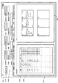
図25は、測定登録ウィンドウ82の構成を示す模式図である。図25に示すように、測定登録ウィンドウ82は、ウィンドウ上部に設けられた測定項目グループ選択ボックス82aと、後述する測定選択項目テーブル82bを表示する測定選択項目テーブル表示領域82cと、後述する測定項目リスト82dを表示する測定項目リスト表示領域82eと、検体に関する情報を入力するための検体情報入力領域82fと、患者に関する情報を表示するための患者情報表示領域82gと、測定選択項目を選択するための複数のボタン82h,82i,82j,82k,82m,82nが表示されるボタン表示領域82oとを有している。   FIG. 25 is a schematic diagram showing the configuration of the measurement registration window 82. As shown in FIG. 25, the measurement registration window 82 includes a measurement item group selection box 82a provided at the top of the window, a measurement selection item table display area 82c for displaying a measurement selection item table 82b described later, and a measurement item described later. In order to select a measurement item list display area 82e for displaying the list 82d, a specimen information input area 82f for inputting information about the specimen, a patient information display area 82g for displaying information about the patient, and a measurement selection item. A plurality of buttons 82h, 82i, 82j, 82k, 82m, and 82n.

測定項目グループ選択ボックス82aは、右端に表示された三角矢印ボタンを左クリックすることによって、測定項目グループのプルダウンメニューが表示されるようになっており、このプルダウンメニューからユーザが所望の測定項目グループを選択することが可能であるようになっている。測定項目グループは、データ処理装置がデータ処理対象とする測定装置毎に予め設定されており、ここでは血球分析に関する測定項目グループとして「MCC」というグループが設定されている場合について説明する。ユーザは、測定項目グループ選択ボックス82aのプルダウンメニューを表示し、その中から「MCC」を選択する。または、データ処理装置3の対象とする測定装置が血球分析装置2a,2bであることから、測定項目グループとして「MCC」がデフォルト設定されていてもよい。この場合には、ユーザが操作を行わなくても「MCC」が選択される。図21〜図23に示すフローチャートでは、説明を簡単にするために、測定項目グループのデフォルト設定で「MCC」が設定されていることとしている。   In the measurement item group selection box 82a, a pull-down menu of measurement item groups is displayed by left-clicking the triangular arrow button displayed at the right end, and the user can select a desired measurement item group from this pull-down menu. It is possible to select. The measurement item group is set in advance for each measurement device to be processed by the data processing device. Here, a case where a group “MCC” is set as a measurement item group related to blood cell analysis will be described. The user displays a pull-down menu of the measurement item group selection box 82a, and selects “MCC” from the pull-down menu. Alternatively, since the measurement device that is the target of the data processing device 3 is the blood cell analyzers 2a and 2b, “MCC” may be set as a default as the measurement item group. In this case, “MCC” is selected without any operation by the user. In the flowcharts shown in FIGS. 21 to 23, “MCC” is set as the default setting of the measurement item group in order to simplify the description.

測定項目グループにMCCが選択されたときには、CPU31aは、測定選択項目テーブル82b及び測定項目リスト82dを作成して夫々測定選択項目テーブル表示領域82c及び測定項目リスト表示領域82eに表示する(ステップS7)。図25に示すように、測定選択項目テーブル82bは、検体番号フィールド82p、ラックフィールド82q、チューブフィールド82r、患者IDフィールド82s、コメントフィールド82t、CBCフィールド82u、DIFFフィールド82v、RETフィールド82w、及びNRBCフィールド82xを有している。検体番号フィールド82pには、ユーザによって入力された検体番号が表示される。ラックフィールド82q及びチューブフィールド82rには、ユーザによって入力されたラック番号及びチューブ番号が表示される。患者IDフィールド82sには、同一レコードの検体番号に対応する患者の患者IDが表示される。コメントフィールド82tには、この検体についてのコメントが入力された場合にこれが表示される。CBCフィールド82uには、対象の検体に対して、測定選択項目としてCBCが選択された場合に、丸印、黒丸印、及び黒三角印のいずれかの記号が表示される。ここで、丸印の記号は、この測定選択項目(CBC)が未測定であることを示し、黒丸印の記号は、この測定選択項目について測定済みであることを示し、黒三角印の記号は、この測定選択項目について測定中であることを示している。CBCとは、白血球数(WBC)、赤血球数(RBC)、血色素量(HGB)、ヘマトクリット値(HCT)、平均赤血球容積(MCV)、平均赤血球血色素量(MCH)、平均赤血球血色素濃度(MCHC)、血小板数(PLT)、赤血球分布幅(RDW−SD)、赤血球分布幅(RDW−CV)、血小板分布幅(PDW)、平均血小板容積(MPV)、大型血小板比率(P−LCR)、及び血小板クリット値(PCT)の測定項目のグループである。DIFFフィールド82vには、対象の検体に対して、測定選択項目としてDIFFが選択された場合に、上記記号が表示される。DIFFとは、好中球数比率(NEUT%)、リンパ球数比率(LYMPH%)、単球数比率(MONO%)、好酸球数比率(EO%)、好塩基球数比率(BASO%)、好中球数(NEUT#)、リンパ球数(LYMPH#)、単球数(MONO#)、好酸球数(EO#)、及び好塩基球数(BASO#)の測定項目のグループである。RETフィールド82wには、対象の検体に対して、測定選択項目としてRETが選択された場合に、上記記号が表示される。RETとは、網赤血球比率(RET%)、網赤血球数(RET#)、高蛍光網赤血球比率(HFR)、中蛍光網赤血球比率(MFR)、低蛍光網赤血球比率(LFR)、及び網赤血球成熟指数(IRF)の測定項目のグループである。NRBCフィールド82xには、対象の検体に対して、測定選択項目としてNRBCが選択された場合に、上記記号が表示される。NRBCとは、有核赤血球数比率(NRBC%)及び有核赤血球数(NRBC#)の測定項目のグループである。図25の例を用いて説明すると、検体番号「801−05」の検体は、CBC、DIFF、及びNRBCが測定選択項目として選択されており、このうちCBC及びNRBCは測定済みであり、DIFFは測定中であることとなる。   When MCC is selected as the measurement item group, the CPU 31a creates the measurement selection item table 82b and the measurement item list 82d and displays them in the measurement selection item table display area 82c and the measurement item list display area 82e, respectively (step S7). . As shown in FIG. 25, the measurement selection item table 82b includes a specimen number field 82p, a rack field 82q, a tube field 82r, a patient ID field 82s, a comment field 82t, a CBC field 82u, a DIFF field 82v, a RET field 82w, and an NRBC. It has a field 82x. The specimen number input by the user is displayed in the specimen number field 82p. In the rack field 82q and the tube field 82r, the rack number and the tube number input by the user are displayed. The patient ID field 82s displays the patient ID of the patient corresponding to the sample number in the same record. This is displayed in the comment field 82t when a comment about this sample is input. In the CBC field 82u, when CBC is selected as a measurement selection item for the target specimen, any one of a circle mark, a black circle mark, and a black triangle mark is displayed. Here, a circle symbol indicates that the measurement selection item (CBC) has not been measured, a black circle symbol indicates that the measurement selection item has been measured, and a black triangle symbol represents This indicates that the measurement selection item is being measured. CBC means white blood cell count (WBC), red blood cell count (RBC), hemoglobin content (HGB), hematocrit value (HCT), average red blood cell volume (MCV), average red blood cell hemoglobin content (MCH), average red blood cell hemoglobin concentration (MCHC) , Platelet count (PLT), red blood cell distribution width (RDW-SD), red blood cell distribution width (RDW-CV), platelet distribution width (PDW), average platelet volume (MPV), large platelet ratio (P-LCR), and platelets This is a group of measurement items of crit value (PCT). In the DIFF field 82v, the symbol is displayed when DIFF is selected as a measurement selection item for the target specimen. DIFF means neutrophil count ratio (NEUT%), lymphocyte count ratio (LYMPH%), monocyte count ratio (MONO%), eosinophil count ratio (EO%), basophil count ratio (BASO%). ), Neutrophil count (NEUT #), lymphocyte count (LYMPH #), monocyte count (MONO #), eosinophil count (EO #), and basophil count (BASO #) It is. In the RET field 82w, the above symbol is displayed when RET is selected as the measurement selection item for the target sample. RET means reticulocyte ratio (RET%), reticulocyte count (RET #), high fluorescent reticulocyte ratio (HFR), medium fluorescent reticulocyte ratio (MFR), low fluorescent reticulocyte ratio (LFR), and reticulocyte It is a group of measurement items of maturity index (IRF). The above symbol is displayed in the NRBC field 82x when NRBC is selected as a measurement selection item for the target specimen. The NRBC is a group of measurement items of the nucleated red blood cell count ratio (NRBC%) and the nucleated red blood cell count (NRBC #). Referring to the example of FIG. 25, CBC, DIFF, and NRBC are selected as measurement selection items for the sample with the sample number “801-05”. Among these, CBC and NRBC have been measured, and DIFF is Measurement is in progress.

このような測定選択項目テーブル82bに表示されたレコードのうち、ユーザによって1つの検体番号に関する行が選択されたときには、この行が他の行とは異なる色でハイライト表示される。そして、CPU31aは、この選択された検体番号について測定項目の設定状態を測定項目リスト82dに表示する。図25に示すように、測定項目リスト82dには、血球分析における測定項目がリスト表示され、夫々の測定項目について測定対象として設定されている場合には丸印が表示されるようになっている。図25の例で説明すると、検体番号「801−04」の行が選択されており、この検体については測定選択項目としてCBCとNRBCとが設定されているので、測定項目リスト82dでは、WBC,RBC,HGB,HCT,MCV,MCH,MCHC,PLT,RDW−SD,RDW−CV,PDW,MPV,P−LCR,PCT,NRBC%,NRBC#に対して丸印が表示されることとなる。   Among the records displayed in the measurement selection item table 82b, when the user selects a row relating to one specimen number, this row is highlighted in a color different from the other rows. Then, the CPU 31a displays the measurement item setting state for the selected sample number in the measurement item list 82d. As shown in FIG. 25, the measurement item list 82d displays a list of measurement items in blood cell analysis, and when each measurement item is set as a measurement target, a circle is displayed. . In the example of FIG. 25, the row of the sample number “801-04” is selected, and for this sample, CBC and NRBC are set as measurement selection items. Therefore, in the measurement item list 82d, WBC, Circles are displayed for RBC, HGB, HCT, MCV, MCH, MCHC, PLT, RDW-SD, RDW-CV, PDW, MPV, P-LCR, PCT, NRBC%, and NRBC #.

また、検体情報入力領域82fには、入力された検体情報が表示され、患者情報表示領域82gには、この検体情報に対応する患者情報が表示される。検体情報入力領域82fには、検体番号、ラック、チューブ、及びコメントを入力するための入力ボックスが設けられており、ユーザはこれらの入力ボックスにカーソルを移動させた状態でこれらの検体情報(検体番号、ラック、チューブ、及びコメント)を入力することが可能である。これらの入力ボックスに入力された結果は測定選択項目テーブル82bに反映され、データベースDB21に該当データが登録される。また、患者情報表示領域82gには、患者ID、名字、名前、性別、生年月日、病棟、担当医、及び患者コメントを表示するための表示ボックスが設けられており、これらの表示ボックスに該当する患者の情報が表示される。ここで、検体情報がユーザによって入力されたとき場合には(ステップS8でYes)、CPU31aがデータベースサーバ7にこの検体番号を送信し、この検体番号に対応する患者情報をデータベースサーバ7に問い合わせる。データベースサーバ7は、かかる検体番号を検索キーとして患者情報を検索し、前記検体番号に対応する患者情報をデータ処理装置3へと送信する。このようにして、CPU31aは患者情報を取得する(ステップS9)。図25の例を用いて説明すると、検体番号の入力ボックスに「801−04」が、コメントの入力ボックスに「コメント」が夫々入力されている。このとき、データ処理装置3は、検体番号「801−04」を示すデータをデータベースサーバ7へと送信し、対応する患者情報を要求する。データベースサーバ7は、検体番号「801−04」を検索キーとして対応する患者情報を検索し、この結果、この検体に対応する患者情報を獲得する。データベースサーバ7は、かかる患者情報をデータ処理装置3へと送信し、データ処理装置3は、受信した患者情報である患者の患者ID「ABC12345」、名字「シスメックス」、名前「タロウ」、性別「Male」、生年月日「1943/01/15」、病棟「01」、担当医「0839」を患者情報表示領域82gの夫々対応する表示ボックスに表示させる。   The input specimen information is displayed in the specimen information input area 82f, and patient information corresponding to the specimen information is displayed in the patient information display area 82g. The sample information input area 82f is provided with an input box for inputting a sample number, rack, tube, and comment, and the user moves the cursor to these input boxes and inputs the sample information (sample). Number, rack, tube, and comment). The results input in these input boxes are reflected in the measurement selection item table 82b, and the corresponding data is registered in the database DB21. The patient information display area 82g is provided with display boxes for displaying the patient ID, surname, name, gender, date of birth, ward, doctor in charge, and patient comments. Patient information is displayed. Here, when the sample information is input by the user (Yes in step S8), the CPU 31a transmits the sample number to the database server 7 and inquires the database server 7 about patient information corresponding to the sample number. The database server 7 searches for patient information using the sample number as a search key, and transmits patient information corresponding to the sample number to the data processing device 3. Thus, CPU31a acquires patient information (step S9). Referring to the example of FIG. 25, “801-04” is entered in the sample number input box, and “comment” is entered in the comment input box. At this time, the data processing device 3 transmits data indicating the sample number “801-04” to the database server 7 and requests corresponding patient information. The database server 7 searches corresponding patient information using the sample number “801-04” as a search key, and as a result, acquires patient information corresponding to the sample. The database server 7 transmits the patient information to the data processing device 3, and the data processing device 3 receives the patient ID “ABC12345”, the last name “Sysmex”, the name “Taro”, the gender “ “Male”, date of birth “1943/01/15”, ward “01”, and attending physician “0839” are displayed in corresponding display boxes in the patient information display area 82g.

また、測定項目リスト表示領域82eの右方には、ボタン82h,82i,82j,82k,82m,82nが縦に並べられて設けられている。ボタン82hは、CBCを登録するためのボタンであり、ユーザがこのボタン82hを左クリックすることにより、その時点で検体情報入力領域82fの入力ボックスに入力されている検体番号に対して、測定選択項目としてCBCが登録される。同様に、ボタン82i,82j,82k,82m,82nは、夫々CBC+DIFF,CBC+DIFF+RET,CBC+DIFF+RET+NRBC,RET,NRBCを測定選択項目として登録するためのボタンである。検体情報が入力され、患者情報が表示された状態で、更にユーザがボタン82iを左クリックした場合(ステップS10でYes)、CPU31aは、測定選択項目テーブル82bに新たな行を追加し、入力ボックスに入力された検体番号をこの行の検体番号フィールドに表示し、CBCフィールド及びDIFFフィールドに丸印を表示する(ステップS11)。また、ステップS11の処理では、測定項目リスト82dにおいて、WBC,RBC,HGB,HCT,MCV,MCH,MCHC,PLT,RDW−SD,RDW−CV,PDW,MPV,P−LCR,PCT,NEUT%,LYMPH%,MONO%,EO%,BASO%,NEUT#,LYMPH#,MONO#,EO#,BASO#に対して丸印が表示されることとなる。また、CPU31aは、データベースDB21にアクセスして、これらの検体情報、患者情報、および測定項目を登録する(ステップS12)。このようにして、新たな検体についての測定登録を行うことが可能である。   Further, buttons 82h, 82i, 82j, 82k, 82m, and 82n are vertically arranged on the right side of the measurement item list display area 82e. The button 82h is a button for registering the CBC. When the user left-clicks the button 82h, the measurement selection is performed for the sample number currently input in the input box of the sample information input area 82f. CBC is registered as an item. Similarly, buttons 82i, 82j, 82k, 82m, and 82n are buttons for registering CBC + DIFF, CBC + DIFF + RET, CBC + DIFF + RET + NRBC, RET, and NRBC as measurement selection items, respectively. When the sample information is input and the patient information is displayed and the user further left-clicks the button 82i (Yes in step S10), the CPU 31a adds a new line to the measurement selection item table 82b, and inputs the input box. Is displayed in the sample number field of this row, and circles are displayed in the CBC field and DIFF field (step S11). In the process of step S11, in the measurement item list 82d, WBC, RBC, HGB, HCT, MCV, MCH, MCHC, PLT, RDW-SD, RDW-CV, PDW, MPV, P-LCR, PCT, NEUT% , LYMPH%, MONO%, EO%, BASO%, NEUT #, LYMPH #, MONOP #, EO #, BASO # are displayed as circles. Further, the CPU 31a accesses the database DB21 and registers these sample information, patient information, and measurement items (step S12). In this way, measurement registration for a new sample can be performed.

検体の測定を開始する場合、オペレータは、検体が収容された採血管をラックにセットし、このラックを血球分析装置2a(2b)の前部に設けられた搬送部にセットする。採血管には、この検体の検体番号を示すバーコードラベルが貼付されている。搬送部によって、血球分析装置2a(2b)の試料供給部(図示せず)の下方の検体供給位置に採血管がラックごと搬送され、その途中で血球分析装置2aに設けられたバーコードリーダによって前記バーコードが読み取られる。血球分析装置2aの制御部25は、このようにバーコードから読み取られた検体番号を示す検体番号データをデータ処理装置3へと送信する。CPU31aは、血球分析装置2aから検体番号データを受信した場合には(ステップS13でYes)、この検体番号について前述したような測定登録のデータが存在するか否かを判別する(ステップS14)。この処理は、データベースDB21を参照して該当する検体番号のレコードが存在するか否かを判別することによって行われる。ステップS14の処理で、この検体番号について測定登録データが存在する場合には(ステップS14でYes)、CPU31aは、データベースDB21からこの検体番号に対応する測定項目を読み出し(ステップS15)、後述するステップS18へと処理を移す。   When starting the measurement of the sample, the operator sets the blood collection tube in which the sample is stored in the rack, and sets the rack in the transport unit provided at the front of the blood cell analyzer 2a (2b). A barcode label indicating the sample number of the sample is attached to the blood collection tube. The blood collection tube is transported together with the rack to the sample supply position below the sample supply unit (not shown) of the blood cell analyzer 2a (2b) by the transport unit, and a barcode reader provided in the blood cell analyzer 2a in the middle thereof The bar code is read. The control unit 25 of the blood cell analyzer 2a transmits the sample number data indicating the sample number read from the barcode in this way to the data processing device 3. When the CPU 31a receives the sample number data from the blood cell analyzer 2a (Yes in step S13), the CPU 31a determines whether or not the above-described measurement registration data exists for this sample number (step S14). This process is performed by referring to the database DB 21 to determine whether there is a record of the corresponding sample number. If measurement registration data exists for this sample number in the process of step S14 (Yes in step S14), the CPU 31a reads out a measurement item corresponding to this sample number from the database DB 21 (step S15), and will be described later. The process proceeds to S18.

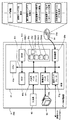
一方、ステップS14において、この検体番号について測定登録データが存在しない場合には(ステップS14でNo)、CPU31aは、検体番号データをデータベースサーバ7へと送信し、この検体の測定項目を問い合わせる(ステップS16)。このときのデータの流れを図26を用いて説明する。図26は、測定装置へのオーダ発行までのデータの流れを示す模式図である。血球分析装置2aからの検体番号データの受信は、通信モジュール35eによって実行される。通信モジュール35eによって受信された検体番号データは、キュー83aに入れられる。キュー83aから取り出された検体番号データは、ビジネスロジック層34cのプログラムモジュール(例えば共通ロジックモジュール35f)に与えられ、このプログラムモジュールから通信モジュール35eへと送られる。そして、通信モジュール35eは、受け取った検体番号データをデータベースサーバ7へと送信し、これによって測定項目の問い合わせが行われる。   On the other hand, if there is no measurement registration data for this sample number in Step S14 (No in Step S14), the CPU 31a transmits the sample number data to the database server 7 and inquires about the measurement item of this sample (Step S14). S16). The data flow at this time will be described with reference to FIG. FIG. 26 is a schematic diagram showing a data flow until order issuance to the measuring apparatus. Reception of the sample number data from the blood cell analyzer 2a is executed by the communication module 35e. The sample number data received by the communication module 35e is placed in the queue 83a. The specimen number data taken out from the queue 83a is given to a program module (for example, common logic module 35f) of the business logic layer 34c, and is sent from the program module to the communication module 35e. Then, the communication module 35e transmits the received sample number data to the database server 7, thereby inquiring about the measurement item.

データベースサーバ7は、検体番号データを検索キーとして、この検体に対応する測定項目を検索する。検索の結果得られた測定項目は、測定項目データとして要求元のデータ処理装置3へと送信される。CPU31aは、測定項目データを受信した場合には(ステップS17でYes)、この測定項目データをRAM31cに設けられたオーダ発行用測定項目管理バッファ83bに格納する(ステップS18)。このときのデータの流れを図26を用いて説明する。データベースサーバ7からの測定項目データの受信は、通信モジュール35eによって実行される。通信モジュール35eによって受信された測定項目データは、キュー83aに入れられる。キュー83aから取り出された測定項目データは、ビジネスロジック層34cのプログラムモジュール(例えば、共通ロジックモジュール35f)に与えられる。このプログラムモジュールは、取り出した測定項目データを、検体番号データと対応付けてオーダ発行用測定項目管理バッファ83bに格納する。   The database server 7 searches for a measurement item corresponding to this sample using the sample number data as a search key. The measurement item obtained as a result of the search is transmitted to the requesting data processing apparatus 3 as measurement item data. When the measurement item data is received (Yes in step S17), the CPU 31a stores the measurement item data in the order issue measurement item management buffer 83b provided in the RAM 31c (step S18). The data flow at this time will be described with reference to FIG. Reception of the measurement item data from the database server 7 is executed by the communication module 35e. The measurement item data received by the communication module 35e is put in the queue 83a. The measurement item data taken out from the queue 83a is given to a program module (for example, the common logic module 35f) of the business logic layer 34c. This program module stores the extracted measurement item data in the order issue measurement item management buffer 83b in association with the sample number data.

その後、例えば血球分析装置2aの検体供給位置に測定対象の検体が収容された採血管が到達したことを、図示しないセンサによって制御部25が検出したときに、制御部25は測定項目の送信を要求する送信要求データをデータ処理装置3へと送信する。この送信要求データには、測定対象の検体の検体番号データが含まれている。CPU31aは、この送信要求データを受信した場合に(ステップS19でYes)、この送信要求データに含まれる検体番号データに対応する測定項目データをオーダ発行用測定項目管理バッファ83bから取得し(ステップS20)、この測定項目データを血球分析装置2aへと送信する(ステップS21)。このときのデータの流れを図26を用いて説明する。血球分析装置2aからの送信要求データの受信は、通信モジュール35eによって実行される。通信モジュール35eによって受信された送信要求データは、キュー83aに入れられる。キュー83aから取り出された送信要求データは、ビジネスロジック層34cのプログラムモジュール(例えば、共通ロジックモジュール35f)に与えられる。このプログラムモジュールは、取り出した送信要求データに含まれる検体番号データに対応する測定項目データをオーダ発行用測定項目管理バッファ83bから読み出し、この測定項目データを通信モジュール35eに与える。そして、通信モジュール35eは、受け取った測定項目データを血球分析装置2aに送信する。   Thereafter, for example, when the control unit 25 detects that the blood collection tube containing the sample to be measured has reached the sample supply position of the blood cell analyzer 2a by a sensor (not shown), the control unit 25 transmits the measurement item. The requested transmission request data is transmitted to the data processing device 3. This transmission request data includes the sample number data of the sample to be measured. When the CPU 31a receives this transmission request data (Yes in step S19), the CPU 31a acquires measurement item data corresponding to the sample number data included in the transmission request data from the order issue measurement item management buffer 83b (step S20). The measurement item data is transmitted to the blood cell analyzer 2a (step S21). The data flow at this time will be described with reference to FIG. Reception of the transmission request data from the blood cell analyzer 2a is executed by the communication module 35e. The transmission request data received by the communication module 35e is put in the queue 83a. The transmission request data extracted from the queue 83a is given to a program module (for example, the common logic module 35f) of the business logic layer 34c. This program module reads measurement item data corresponding to the sample number data included in the extracted transmission request data from the order issue measurement item management buffer 83b, and provides this measurement item data to the communication module 35e. Then, the communication module 35e transmits the received measurement item data to the blood cell analyzer 2a.

その後、血球分析装置2aの制御部25は、試料供給部に採血管から検体を吸引させる。この吸引が完了した後に、制御部25は、吸引の完了を通知するための吸引完了通知データをデータ処理装置3へ送信する。この吸引完了通知データには、吸引した検体の検体番号データが含まれている。CPU31aは、この吸引完了通知データを受信した場合に(ステップS22でYes)、この吸引完了通知データに含まれる検体番号データに対応する測定項目データをオーダ発行用測定項目管理バッファ83bから取得し(ステップS23)、検体番号に対応付けてデータベースDB21に登録する(ステップS24)。このときのデータの流れを図26を用いて説明する。血球分析装置2aからの吸引完了通知データの受信は、通信モジュール35eによって実行される。通信モジュール35eによって受信された吸引完了通知データは、キュー83aに入れられる。キュー83aから取り出された吸引完了通知データは、ビジネスロジック層34cのプログラムモジュール(例えば、共通ロジックモジュール35f)に与えられる。このプログラムモジュールは、取り出した吸引完了通知データに含まれる検体番号データに対応する測定項目データをオーダ発行用測定項目管理バッファ83bから読み出し、この測定項目データと検体番号データとをデータベースアクセスモジュール35hに与える。そして、データベースアクセスモジュール35hは、検体番号と測定項目とを対応付けてデータベースDB21に登録する。   Thereafter, the control unit 25 of the blood cell analyzer 2a causes the sample supply unit to suck the sample from the blood collection tube. After the suction is completed, the control unit 25 transmits suction completion notification data for notifying the completion of the suction to the data processing device 3. This aspiration completion notification data includes sample number data of the aspirated sample. When the CPU 31a receives the suction completion notification data (Yes in step S22), the CPU 31a acquires measurement item data corresponding to the sample number data included in the suction completion notification data from the order issue measurement item management buffer 83b ( In step S23), the sample number is registered in the database DB 21 in association with the sample number (step S24). The data flow at this time will be described with reference to FIG. Reception of the suction completion notification data from the blood cell analyzer 2a is executed by the communication module 35e. The suction completion notification data received by the communication module 35e is placed in the queue 83a. The suction completion notification data extracted from the queue 83a is given to a program module (for example, the common logic module 35f) of the business logic layer 34c. The program module reads measurement item data corresponding to the sample number data included in the extracted suction completion notification data from the order issue measurement item management buffer 83b, and sends the measurement item data and the sample number data to the database access module 35h. give. Then, the database access module 35h registers the sample number and the measurement item in the database DB 21 in association with each other.

次に、血球分析装置2aは、採血管から吸引した検体を光学式検出部21、RBC検出部22、HGB検出部23、及びIMI検出部24の何れかに供給し、データ処理装置3から与えられた測定項目について測定を開始する。測定終了後は、制御部25が測定値データをデータ処理装置3へと送信する。この測定値データには、検体番号データが含まれている。CPU31aは、この測定値データを受信した場合に(ステップS25でYes)、データベースDB21に検体番号に対応付けて測定値を登録する(ステップS26)。ここで、ユーザが測定結果の表示を指示する入力を行った場合には(ステップS27でYes)、CPU31aは、データベースDB21から測定値データを読み出し(ステップS28)、測定結果表示ウィンドウを表示する(ステップS29)。本実施の形態1においては、測定結果表示ウィンドウの表示は、ユーザがメニューウィンドウ81e内のサンプルエクスプローラボタン81hを左クリックした場合に実行される。   Next, the blood cell analyzer 2a supplies the sample aspirated from the blood collection tube to any one of the optical detector 21, the RBC detector 22, the HGB detector 23, and the IMI detector 24, and gives it from the data processor 3. Measurement is started for the measured item. After the measurement is completed, the control unit 25 transmits measurement value data to the data processing device 3. The measurement value data includes specimen number data. When the CPU 31a receives the measurement value data (Yes in step S25), the CPU 31a registers the measurement value in the database DB 21 in association with the sample number (step S26). When the user inputs an instruction to display the measurement result (Yes in step S27), the CPU 31a reads the measurement value data from the database DB 21 (step S28) and displays the measurement result display window ( Step S29). In the first embodiment, the measurement result display window is displayed when the user left-clicks the sample explorer button 81h in the menu window 81e.

図27は、測定結果表示ウィンドウ84の構成を示す模式図である。図27に示すように、測定結果表示ウィンドウ84は、後述する検体情報テーブル84aを表示する検体情報テーブル表示領域84bと、後述する数値データテーブル84cを表示する数値データテーブル表示領域84dと、患者に関する情報を表示するための患者情報表示領域84eとを有している。患者情報表示領域84eは、上述した測定登録ウィンドウ82の患者情報表示領域82gと同様であるので、その説明を省略する。   FIG. 27 is a schematic diagram showing the configuration of the measurement result display window 84. As shown in FIG. 27, the measurement result display window 84 includes a specimen information table display area 84b for displaying a specimen information table 84a to be described later, a numerical data table display area 84d for displaying a numerical data table 84c to be described later, and a patient-related information. A patient information display area 84e for displaying information. Since the patient information display area 84e is the same as the patient information display area 82g of the measurement registration window 82 described above, description thereof is omitted.

上述したように、サンプルエクスプローラボタン81hが左クリックされた場合には、CPU31aは、過去に測定が行われた検体に関する検体情報及び当該検体に関する測定値データをデータベースDB21から取得し、これらの情報から検体情報テーブル84a及び数値データテーブル84cを作成して夫々検体情報テーブル表示領域84b及び数値データテーブル表示領域84dに表示し、また患者情報を患者情報表示領域84eに表示する(ステップS30)。図27に示すように、検体情報テーブル84aには、検体番号フィールド84f、測定装置IDフィールド84h、測定時刻フィールド84i、及び測定値フィールド84j,84k,84m,84n,84o,84p,84q,84rを有している。検体番号フィールド84fには、過去に測定された検体の検体番号が表示される。測定装置IDフィールド84hには、検体を測定した測定装置の測定装置IDが表示される。測定時刻フィールド84iには、検体を測定した時刻が表示される。測定値フィールド84j,84k,84m,84n,84o,84p,84q,84rには、検体の各測定値が表示される。このような検体情報テーブル表示領域84bの下部には、測定項目切替タブ84s〜84uが設けられている。ここでは、CBCタブ84s、DIFFタブ84t、及びRETタブ84uが設けられている場合について説明する。CBCタブ84sが選択されているときには、測定値フィールド84j,84k,84m,84n,84o,84p,84q,84rに、WBC,RBC,HGB,HCT,MCV,MCH,MCHC,PLTの各測定値が表示されるようになっている。DIFFタブ84tがクリックされた場合には、検体情報テーブル84aが切り替わり、測定値フィールドにDIFFの測定項目についての測定値が表示される。またRETタブ84uが選択されたときには、測定値フィールドにRETの測定項目についての測定値が表示される。なお、検体番号フィールド84f、測定装置IDフィールド84h、測定時刻フィールド84iはどのタブが選択されている場合でも表示される。また、この他にも、NRBCタブを設けて、このタブが選択されているときには、NRBCの測定項目についての測定値が表示されるようにしてもよい。   As described above, when the sample explorer button 81h is left-clicked, the CPU 31a obtains the sample information related to the sample that has been measured in the past and the measurement value data related to the sample from the database DB 21, and from these information A specimen information table 84a and a numerical data table 84c are created and displayed in the specimen information table display area 84b and the numerical data table display area 84d, respectively, and patient information is displayed in the patient information display area 84e (step S30). As shown in FIG. 27, the sample information table 84a includes a sample number field 84f, a measurement device ID field 84h, a measurement time field 84i, and measurement value fields 84j, 84k, 84m, 84n, 84o, 84p, 84q, and 84r. Have. The specimen number field 84f displays the specimen number of the specimen measured in the past. The measurement device ID field 84h displays the measurement device ID of the measurement device that measured the sample. In the measurement time field 84i, the time when the sample is measured is displayed. In the measurement value fields 84j, 84k, 84m, 84n, 84o, 84p, 84q, and 84r, each measurement value of the specimen is displayed. Measurement item switching tabs 84s to 84u are provided below the specimen information table display area 84b. Here, a case where the CBC tab 84s, the DIFF tab 84t, and the RET tab 84u are provided will be described. When the CBC tab 84s is selected, the measurement values 84j, 84k, 84m, 84n, 84o, 84p, 84q, and 84r have WBC, RBC, HGB, HCT, MCV, MCH, MCHC, and PLT measurement values. It is displayed. When the DIFF tab 84t is clicked, the sample information table 84a is switched, and the measurement value for the DIFF measurement item is displayed in the measurement value field. When the RET tab 84u is selected, the measurement value for the RET measurement item is displayed in the measurement value field. The sample number field 84f, the measurement device ID field 84h, and the measurement time field 84i are displayed regardless of which tab is selected. In addition to this, an NRBC tab may be provided, and when this tab is selected, a measurement value for an NRBC measurement item may be displayed.

このような検体情報テーブル84aに表示されたレコードのうち、ユーザによって1つの検体番号に関する行が選択されたときには、この行が他の行とは異なる色でハイライト表示される。そして、CPU31aは、この選択された検体番号についての測定値を数値データテーブル84cに表示する。図27に示すように、数値データテーブル84cは、血球分析における測定項目フィールド84v、数値データフィールド84w、及び単位フィールド84xを有している。測定項目フィールド84vには、測定項目の名称が表示される。数値データフィールド84wには、その行の測定項目に対応する検体の測定値が表示される。単位フィールド84xには、その行の測定値の単位が表示される。このような測定結果表示ウィンドウ84が表示されることによって、ユーザは血球分析装置2aによる測定結果を確認することができる。   Among the records displayed in the sample information table 84a, when the user selects a row related to one sample number, this row is highlighted in a color different from the other rows. Then, the CPU 31a displays the measured value for the selected sample number in the numerical data table 84c. As shown in FIG. 27, the numerical data table 84c has a measurement item field 84v, a numerical data field 84w, and a unit field 84x in blood cell analysis. In the measurement item field 84v, the name of the measurement item is displayed. In the numerical data field 84w, the measurement value of the sample corresponding to the measurement item in the row is displayed. In the unit field 84x, the unit of the measurement value of the row is displayed. By displaying such a measurement result display window 84, the user can confirm the measurement result obtained by the blood cell analyzer 2a.

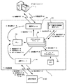
データ処理装置3が血球分析装置2aから測定値データを受信してから、測定結果表示ウィンドウを表示するまでのデータの流れを図を用いて説明する。図28は、データ処理装置3が測定装置から測定値データを受信してから、測定結果を表示するまでのデータの流れを示す模式図である。血球分析装置2aからの測定値データの受信は、通信モジュール35eによって実行される。通信モジュール35eによって受信された測定値データはキュー83aに入れられる。キュー83aから取り出された測定値データは、ビジネスロジック層34cのプログラムモジュール(例えば共通ロジックモジュール35f)に与えられ、このプログラムモジュールからデータベースアクセスモジュール35hへと送られる。そして、データベースアクセスモジュール35hは、受け取った測定値データを対応する検体番号に関連付けてデータベースサーバDB21に登録する。また、ビジネスロジックモジュールは、ビジネスロジック層34cに属するキーリストマネージャクラス85aへデータベースDB21の内容を書き換えたことを通知する。キーリストマネージャクラス85aは、登録されたレコードの主キーをデータベースアクセスモジュール35hに問合せる。また、キーリストマネージャクラス85aは、アクティブキーリスト管理バッファ85bを参照し、変更対象のキーリストバッファを特定する。RAM31cには、前述したアクティブキーリスト管理バッファ85b及び複数のキーリストバッファ85c〜85eが設けられている。アクティブキーリスト管理バッファ85bは、処理対象のキーリストバッファを特定する情報を格納するバッファであり、キーリストバッファ85c〜85eは、データベースDB21から取得した主キーを格納するバッファである。キーリストマネージャクラス85aは、データベースアクセスモジュール35hから取得した主キーを、アクティブキーリスト管理バッファ85bで特定したキーリストバッファに格納し、次のキーリストバッファをアクティブとするようにアクティブキーリスト管理バッファ85bを更新する。次に、測定結果表示ウィンドウを表示するイベントが発生したときに、ビジネスロジック層34cに属するアイテムクラス85fが、アクティブキーリスト管理バッファ85bを参照して表示すべき測定値に対応するキーリストバッファを特定し、このキーリストバッファを参照して主キーを取得する。アイテムクラス85fは、ビジネスロジック層34cに属するデータマネージャクラス85gにこの主キーを与えて測定値を問い合わせる。データマネージャクラス85gは、測定値データを管理するクラスであり、データベースアクセスモジュール35hを通じてデータベースDB21から測定値データを取得する。こうしてアイテムクラス85fは、主キーに対応する測定値データを取得し、これをビジネスロジック層34cに属する単位換算モジュールに渡す。単位換算モジュールは、測定値データの単位換算を行い、変換後の測定値データを測定結果表示モジュール35b等に与える。そして、測定結果表示ウィンドウの表示が行われる。   The data flow from when the data processing device 3 receives the measurement value data from the blood cell analyzer 2a to when the measurement result display window is displayed will be described with reference to the drawings. FIG. 28 is a schematic diagram showing a data flow from when the data processing device 3 receives the measurement value data from the measurement device to when the measurement result is displayed. The measurement value data is received from the blood cell analyzer 2a by the communication module 35e. The measurement value data received by the communication module 35e is placed in the queue 83a. The measurement value data taken out from the queue 83a is given to a program module (for example, the common logic module 35f) of the business logic layer 34c, and is sent from the program module to the database access module 35h. Then, the database access module 35h registers the received measurement value data in the database server DB 21 in association with the corresponding sample number. The business logic module notifies the key list manager class 85a belonging to the business logic layer 34c that the contents of the database DB 21 have been rewritten. The key list manager class 85a inquires of the database access module 35h about the primary key of the registered record. Further, the key list manager class 85a refers to the active key list management buffer 85b, and specifies the key list buffer to be changed. The RAM 31c is provided with the aforementioned active key list management buffer 85b and a plurality of key list buffers 85c to 85e. The active key list management buffer 85b is a buffer for storing information for specifying a key list buffer to be processed, and the key list buffers 85c to 85e are buffers for storing primary keys acquired from the database DB21. The key list manager class 85a stores the primary key acquired from the database access module 35h in the key list buffer specified by the active key list management buffer 85b, and activates the next key list buffer so as to activate the next key list buffer. 85b is updated. Next, when an event for displaying the measurement result display window occurs, the item class 85f belonging to the business logic layer 34c refers to the active key list management buffer 85b to display a key list buffer corresponding to the measurement value to be displayed. The primary key is obtained by referring to this key list buffer. The item class 85f gives the primary key to the data manager class 85g belonging to the business logic layer 34c and inquires about the measured value. The data manager class 85g is a class for managing measured value data, and acquires measured value data from the database DB21 through the database access module 35h. In this way, the item class 85f acquires measurement value data corresponding to the primary key, and passes this to the unit conversion module belonging to the business logic layer 34c. The unit conversion module performs unit conversion of the measurement value data, and provides the converted measurement value data to the measurement result display module 35b and the like. Then, the measurement result display window is displayed.

また、ユーザが測定結果の詳細情報の表示を指示する入力を行った場合には(ステップS31でYes)、CPU31aは、データベースDB21から測定値データを読み出し(ステップS32)、測定結果詳細情報表示ウィンドウを表示する(ステップS33)。本実施の形態1においては、ユーザが測定結果表示ウィンドウ84内の検体情報テーブル84aをダブルクリックした場合に測定結果詳細情報表示ウィンドウが開き、この測定結果詳細情報表示ウィンドウには、ダブルクリックされたデータについての詳細情報が表示される。また、測定結果詳細情報表示ウィンドウは、ユーザがメニューウィンドウ81e内のデータブラウザボタン81iを左クリックした場合等にも表示される。   When the user inputs an instruction to display the detailed information of the measurement result (Yes in step S31), the CPU 31a reads the measurement value data from the database DB 21 (step S32), and the measurement result detailed information display window Is displayed (step S33). In the first embodiment, when the user double-clicks the sample information table 84a in the measurement result display window 84, the measurement result detailed information display window is opened, and the measurement result detailed information display window is double-clicked. Detailed information about the data is displayed. The measurement result detailed information display window is also displayed when the user left-clicks the data browser button 81i in the menu window 81e.

図29は、測定結果詳細情報表示ウィンドウ86の構成を示す模式図である。図29に示すように、測定結果詳細情報表示ウィンドウ86は、測定結果に異常が認められるか否かを表示する異常表示領域86aと、検体情報を表示する検体情報表示領域86bと、測定結果の各種詳細情報を表示する詳細情報表示領域86cとを有している。異常表示領域86aは、測定結果詳細情報表示ウィンドウ86の左上部に設けられ、血球測定値あるいは血球像に異常が認められた場合には「Positive」と表示され、これがダブルクリックされることによって異常の分類を表示するようになっている。また、この異常表示領域86aには、異常および測定エラーのない場合に「Negative」と表示されるようになっている。また、検体情報表示領域86bには、検体番号、患者ID、患者名、性別、生年月日、病棟、担当医、測定年月日、測定時刻、及びコメントを表示するための表示ボックスが設けられており、これらの表示ボックスに該当する検体の情報が表示される。   FIG. 29 is a schematic diagram showing the configuration of the measurement result detailed information display window 86. As shown in FIG. 29, the measurement result detailed information display window 86 includes an abnormality display area 86a for displaying whether or not an abnormality is recognized in the measurement result, a specimen information display area 86b for displaying specimen information, and a measurement result. A detailed information display area 86c for displaying various kinds of detailed information. The abnormality display area 86a is provided in the upper left part of the measurement result detailed information display window 86. When an abnormality is observed in the blood cell measurement value or blood cell image, “Positive” is displayed. The classification is displayed. In the abnormality display area 86a, “Negative” is displayed when there is no abnormality and no measurement error. The sample information display area 86b is provided with a display box for displaying a sample number, patient ID, patient name, sex, date of birth, ward, doctor in charge, measurement date, measurement time, and comment. The information on the corresponding sample is displayed in these display boxes.

詳細情報表示領域86cには、各種測定結果に関する詳細情報を表示するためのウィンドウが表示される。図29では、詳細情報表示領域86cに血球分析メインウィンドウ86dを表示した場合を示している。血球分析メインウィンドウ86dは、各測定項目の数値データを表示するための数値データ表示領域86eと、5分類された白血球の個数及び比率を表示するための白血球5分類表示領域86fと、各種の測定項目について、検体が異常であること、又は以上の疑いがあることを示すIPメッセージを表示するフラグ表示領域86gとを有している。   In the detailed information display area 86c, a window for displaying detailed information regarding various measurement results is displayed. FIG. 29 shows a case where the blood cell analysis main window 86d is displayed in the detailed information display area 86c. The blood cell analysis main window 86d includes a numerical data display area 86e for displaying numerical data of each measurement item, a white blood cell 5 classification display area 86f for displaying the number and ratio of five classified white blood cells, and various measurements. The item has a flag display area 86g for displaying an IP message indicating that the specimen is abnormal or suspected as described above.

数値データ表示領域86eには、各測定項目についての数値データとその単位とを表示する数値データテーブル86hが表示される。この数値データテーブル86hは、測定項目、数値データ、及び単位のフィールドを有しており、測定項目毎に数値データが表形式で表示されるようになっている。また、数値データテーブル86hには、各測定項目毎に測定数値の正常範囲からのずれをグラフィカル表示するSDバーが表示されるようになっており、これによりユーザが測定数値の正常範囲に対するずれの程度を容易に確認することができるようになっている。   In the numerical data display area 86e, a numerical data table 86h for displaying numerical data and units for each measurement item is displayed. The numerical data table 86h has fields of measurement items, numerical data, and units, and the numerical data is displayed in a table format for each measurement item. In addition, the numerical data table 86h displays an SD bar for graphically displaying the deviation of the measured numerical value from the normal range for each measurement item. The degree can be easily confirmed.

白血球5分類表示領域86fには、白血球の個数に関する測定項目についての数値データとその単位とを表示する白血球個数データテーブル86iと、白血球の個数の比率に関する測定項目についての数値データとその単位を表示する白血球比率データテーブル86jとが表示される。白血球個数データテーブル86iは、測定項目、数値データ、及び単位のフィールドを有しており、白血球の個数に関する測定項目、即ちNEUT#、LYMPH#、MONO#、EO#、及びBASO#について数値データが表形式で表示されるようになっている。また、白血球個数データテーブル86iには、各測定項目毎に測定数値の正常範囲からのずれをグラフィカル表示するSDバーが表示されるようになっている。白血球比率データテーブル86jは、測定項目、数値データ、及び単位のフィールドを有しており、白血球の個数比率に関する測定項目、即ちNEUT%、LYMPH%、MONO%、EO%、及びBASO%について数値データが表形式で表示されるようになっている。   The white blood cell 5 classification display area 86f displays the white blood cell number data table 86i for displaying the numerical data regarding the measurement items regarding the number of white blood cells and the unit thereof, and the numerical data regarding the measurement items regarding the ratio of the number of white blood cells and the unit thereof. The white blood cell ratio data table 86j to be displayed is displayed. The white blood cell count data table 86i has fields of measurement items, numerical data, and units, and numerical data for measurement items related to the number of white blood cells, that is, NEUT #, LYMPH #, MONO #, EO #, and BASO #. It is displayed in tabular format. The white blood cell count data table 86i displays an SD bar for graphically displaying the deviation of the measured numerical value from the normal range for each measurement item. The white blood cell ratio data table 86j has fields of measurement items, numerical data, and units, and numerical data on measurement items related to the white blood cell number ratio, that is, NEUT%, LYMPH%, MONO%, EO%, and BASO%. Is displayed in tabular form.

フラグ表示領域86gには、WBCに関するIPメッセージを表示する第1IPメッセージ表示ボックス86kと、RBC及びRETに関するIPメッセージを表示する第2IPメッセージ表示ボックス86mと、PLTに関するIPメッセージを表示する第3IPメッセージ表示ボックス86nとが表示される。IPメッセージには、検体が明らかに異常であることを示すアブノーマルIPメッセージと、検体に異常の疑いがあることを示すサスペクトIPメッセージとがあり、第1IPメッセージ表示ボックス86k、第2IPメッセージ表示ボックス86m、及び第3IPメッセージ表示ボックス86nには、対応する測定項目についてのIPメッセージがリスト表示されるようになっている。   In the flag display area 86g, a first IP message display box 86k that displays an IP message about WBC, a second IP message display box 86m that displays an IP message about RBC and RET, and a third IP message display that displays an IP message about PLT A box 86n is displayed. The IP message includes an abnormal IP message indicating that the specimen is clearly abnormal, and a suspect IP message indicating that the specimen is suspected of being abnormal, and includes a first IP message display box 86k and a second IP message display box 86m. The third IP message display box 86n displays a list of IP messages for the corresponding measurement items.

上述したように、検体情報テーブル84aの中のデータがダブルクリックされた場合、又はデータブラウザボタン81iが左クリックされた場合等には、CPU31aは、過去に測定が行われた検体に関する検体情報及び当該検体に関する測定値データをデータベースDB21から取得し、これらの情報から数値データテーブル86h、白血球個数データテーブル86i、及び白血球比率データテーブル86jを作成して夫々数値データ表示領域86e及び白血球5分類表示領域86fに表示し、また検体情報を検体情報表示領域86bに、IPメッセージをフラグ表示領域86gに夫々表示する(ステップS34)。そして、ユーザから終了の指示入力を受け付けた場合には、CPU31aは、処理を終了する。なお、上述ような詳細情報表示領域86cには、血球分析メインウィンドウ86dの他、測定結果をグラフ表示するグラフウィンドウ、白血球に関する詳細情報を表示するWBCウィンドウ、赤血球に関する詳細情報を表示するRBCウィンドウ等を開くことができるようになっている。これらのウィンドウの表示は、詳細情報表示領域86cの上部に設けられたタブで切り替えることができる。例えば、「メイン(MCC)」と表記されたタブが左クリックされた場合には、血球分析メインウィンドウ86dが表示され、「グラフ(MCC)」と表記されたタブが左クリックされた場合には、グラフウィンドウが表示されることとなる。   As described above, when the data in the sample information table 84a is double-clicked, or when the data browser button 81i is left-clicked, the CPU 31a displays the sample information on the sample that has been measured in the past, Measurement value data relating to the sample is acquired from the database DB21, and a numerical data table 86h, a white blood cell count data table 86i, and a white blood cell ratio data table 86j are created from these pieces of information to obtain a numerical data display area 86e and a white blood cell 5 classification display area, respectively. 86f, the sample information is displayed in the sample information display area 86b, and the IP message is displayed in the flag display area 86g (step S34). When an end instruction input is received from the user, the CPU 31a ends the process. In the detailed information display area 86c as described above, in addition to the blood cell analysis main window 86d, a graph window for displaying measurement results in a graph, a WBC window for displaying detailed information about white blood cells, an RBC window for displaying detailed information about red blood cells, and the like. Can be opened. The display of these windows can be switched by a tab provided in the upper part of the detailed information display area 86c. For example, when a tab labeled “Main (MCC)” is left-clicked, the blood cell analysis main window 86d is displayed, and when a tab labeled “Graph (MCC)” is left-clicked, A graph window will be displayed.

次に、血液凝固測定装置4a,4bのオペレータであるユーザが、データ処理装置5を使用して血液凝固測定装置4a,4bを動作させ、検体を測定する場合の分析システム1の動作について説明する。まず、オペレータは、アプリケーションプログラム54aを起動する。この場合も、アプリケーションプログラム34aの場合と同様に、コンピュータ5aのCPU51aは、画像表示部52にログオンウィンドウを表示させ、ここでログオンID及びパスワードの入力を受け付けた場合には、ユーザ認証を行う。そして、ユーザ認証が成功した場合には、画像表示部52に初期ウィンドウが表示される。この初期ウィンドウの表示処理は、主として基本表示モジュール35aの機能である。   Next, the operation of the analysis system 1 when a user who is an operator of the blood coagulation measuring devices 4a and 4b operates the blood coagulation measuring devices 4a and 4b using the data processing device 5 to measure a sample will be described. . First, the operator activates the application program 54a. Also in this case, as in the case of the application program 34a, the CPU 51a of the computer 5a displays a logon window on the image display unit 52, and performs user authentication when the logon ID and password are accepted. When the user authentication is successful, an initial window is displayed on the image display unit 52. This initial window display processing is mainly a function of the basic display module 35a.

この初期ウィンドウの構成は、図24に示す血球分析装置2a,2b用のアプリケーションプログラム34aにおける初期ウィンドウ81の構成と同様となっている。これは、アプリケーションプログラム34aと共用している基本表示モジュール35a等によって初期ウィンドウが表示されるためである。また、血球分析装置2a,2b、及び血液凝固測定装置4a,4bは夫々測定装置であるため、これらの測定結果の表示等に使用するアプリケーションプログラム34a,54aの処理内容には共通点が多い。したがって、アプリケーションプログラムの構成の一部を無理なく共通化することができ、アプリケーションプログラム34a,54aの開発工数を低減することができる。また、このようにユーザインタフェースを統一することによって、アプリケーションプログラム毎にユーザインタフェースが異なることによるユーザの負担、例えば各アプリケーションプログラム毎に操作を覚える手間等を軽減することができ、一つのアプリケーションプログラム34aの操作さえ覚えておけば、他のアプリケーションプログラム54aをある程度操作することができ、また操作を容易に覚えることができるので利便性が向上する。   The configuration of the initial window is the same as the configuration of the initial window 81 in the application program 34a for the blood cell analyzers 2a and 2b shown in FIG. This is because the initial window is displayed by the basic display module 35a shared with the application program 34a. Further, since the blood cell analyzers 2a and 2b and the blood coagulation measuring devices 4a and 4b are measuring devices, the processing contents of the application programs 34a and 54a used for displaying these measurement results have a lot in common. Therefore, a part of the configuration of the application program can be shared without difficulty, and the development man-hours of the application programs 34a and 54a can be reduced. Also, by unifying the user interface in this way, it is possible to reduce the burden on the user due to the difference in the user interface for each application program, for example, the trouble of memorizing the operation for each application program, etc., and one application program 34a If only the above operation is memorized, the other application program 54a can be manipulated to some extent, and the operation can be easily memorized, thereby improving convenience.

この初期ウィンドウにおいて、ユーザがメニューウィンドウの測定登録ボタンを左クリックした場合には、CPU51aは、測定登録ウィンドウ182を表示する。図30は、測定登録ウィンドウ182の構成を示す模式図である。図30に示すように、測定登録ウィンドウ182は、ウィンドウ上部に設けられた測定項目グループ選択ボックス182aと、ラック番号を選択するためのラック番号選択ボックス182jと、測定項目テーブル182bを表示する測定項目テーブル表示領域182cと、測定項目リスト182dを表示する測定項目リスト表示領域182eと、検体に関する情報を入力するための検体情報入力領域182fと、患者に関する情報を表示するための患者情報表示領域182gと、測定項目を選択するための複数のボタン182h,182iが表示されるボタン表示領域182oとを有している。このように、測定登録ウィンドウ182の構成は、アプリケーションプログラム34aの測定登録ウィンドウ82の構成と同様となっている。なお、測定項目グループ選択ボックス182a、検体情報入力領域182f、及び患者情報表示領域182gの構成は、測定登録ウィンドウ82の測定項目グループ選択ボックス82a、検体情報入力領域82f、及び患者情報表示領域82gの構成と夫々同様であるので、説明を省略する。   In the initial window, when the user left-clicks the measurement registration button on the menu window, the CPU 51a displays a measurement registration window 182. FIG. 30 is a schematic diagram showing the configuration of the measurement registration window 182. As shown in FIG. As shown in FIG. 30, the measurement registration window 182 includes a measurement item group selection box 182a provided at the top of the window, a rack number selection box 182j for selecting a rack number, and a measurement item for displaying a measurement item table 182b. A table display area 182c, a measurement item list display area 182e for displaying the measurement item list 182d, a specimen information input area 182f for inputting information about the specimen, and a patient information display area 182g for displaying information about the patient And a button display area 182o on which a plurality of buttons 182h and 182i for selecting measurement items are displayed. As described above, the configuration of the measurement registration window 182 is the same as the configuration of the measurement registration window 82 of the application program 34a. The configuration of the measurement item group selection box 182a, the specimen information input area 182f, and the patient information display area 182g is the same as that of the measurement item group selection box 82a, the specimen information input area 82f, and the patient information display area 82g of the measurement registration window 82. Since it is the same as the configuration, description thereof will be omitted.

ここでは、測定項目グループとして、血液凝固測定に関する測定項目グループ「CA_凝固法」というグループが設定されている場合について説明する。このCA_凝固法は、生物活性法により測定される測定項目、即ち、プロトロンビン時間(PT)、活性化部分トロンボプラスチン時間(APTT)、フィブリノーゲン量(Fbg)等の測定項目のグループである。ユーザは、測定項目グループ選択ボックス182aのプルダウンメニューを表示し、その中から「CA_凝固法」を選択する。また、この「CA_凝固法」がデフォルト設定されている場合には、ユーザは入力操作を省略することができる。このように「CA_凝固法」が選択された場合には、CPU51aは測定項目テーブル182b及び測定項目リスト182dを作成し、夫々測定項目テーブル表示領域182c及び測定項目リスト表示領域182eに表示する。   Here, a case where a measurement item group “CA_coagulation method” related to blood coagulation measurement is set as the measurement item group will be described. This CA_coagulation method is a group of measurement items such as prothrombin time (PT), activated partial thromboplastin time (APTT), and fibrinogen amount (Fbg) measured by a bioactivity method. The user displays a pull-down menu of the measurement item group selection box 182a and selects “CA_coagulation method” from the pull-down menu. Further, when the “CA_coagulation method” is set as a default, the user can omit an input operation. Thus, when “CA_coagulation method” is selected, the CPU 51a creates the measurement item table 182b and the measurement item list 182d, and displays them in the measurement item table display area 182c and the measurement item list display area 182e, respectively.

図30に示すように、測定項目テーブル182bは、チューブフィールド182p、検体番号フィールド182q、測定指定フィールド182s、PTフィールド182t、APTTフィールド182u、Fbgフィールド182v、患者IDフィールド182w、及び検体コメントフィールド182xを有している。 チューブフィールド182pには、チューブ番号が表示される。検体番号フィールド182qには、検体情報入力領域182fに入力された検体番号が表示される。PTフィールド182tには、対象の検体に対して、測定項目としてPTが登録されている場合に、丸印、黒丸印、及び黒三角印のいずれかの記号が表示される。これらの記号の意味は、上述したアプリケーションプログラム34aにおける記号の意味と同様であるので、その説明を省略する。APTTフィールド182uには、対象の検体に対して、測定項目としてAPTTが登録されている場合に、上記記号が表示される。また、Fbgフィールド182vには、対象の検体に対して、測定項目としてFbgが登録されている場合に、上記記号が表示される。図30の例を用いて説明すると、ラック番号「3」、チューブ番号「2」、検体番号「123」の検体は、PT、及びFbgが測定項目として登録されており、その両方が未測定であることとなる。   As shown in FIG. 30, the measurement item table 182b includes a tube field 182p, a specimen number field 182q, a measurement designation field 182s, a PT field 182t, an APTT field 182u, an Fbg field 182v, a patient ID field 182w, and a specimen comment field 182x. Have. The tube number is displayed in the tube field 182p. The sample number input to the sample information input area 182f is displayed in the sample number field 182q. In the PT field 182t, when PT is registered as a measurement item for the target specimen, any symbol of a circle mark, a black circle mark, and a black triangle mark is displayed. Since the meaning of these symbols is the same as the meaning of the symbols in the application program 34a described above, the description thereof is omitted. The above symbol is displayed in the APTT field 182u when APTT is registered as a measurement item for the target sample. In the Fbg field 182v, the above symbol is displayed when Fbg is registered as a measurement item for the target sample. Referring to the example of FIG. 30, for the sample with the rack number “3”, the tube number “2”, and the sample number “123”, PT and Fbg are registered as measurement items. There will be.

このような測定項目テーブル182bに表示されたレコードのうち、ユーザによって1つの検体番号に関する行が選択されたときには、この行が他の行とは異なる色でハイライト表示される。そして、CPU51aは、この選択された検体番号について測定項目の設定状態を測定項目リスト182dに表示する。図30に示すように、測定項目リスト182dには、生物活性法における測定項目がリスト表示され、夫々の測定項目について測定対象として設定されている場合には丸印が表示されるようになっている。図30の例で説明すると、検体番号「123」の行が選択されており、この検体については測定項目としてPTとFbgとが登録されているので、測定項目リスト182dでは、PT,Fbgに対して丸印が表示されることとなる。   Among the records displayed in the measurement item table 182b, when the user selects a row related to one specimen number, this row is highlighted in a color different from the other rows. Then, the CPU 51a displays the measurement item setting state for the selected sample number in the measurement item list 182d. As shown in FIG. 30, the measurement item list 182d displays a list of measurement items in the biological activity method, and when each measurement item is set as a measurement target, a circle is displayed. Yes. In the example of FIG. 30, the row of the sample number “123” is selected, and PT and Fbg are registered as measurement items for this sample. Therefore, in the measurement item list 182d, PT and Fbg Will be displayed.

また、測定項目リスト表示領域182eの右方には、ボタン182h,182iが縦に並べられて設けられている。ボタン182hは、PT+APTT+Fbgを登録するためのボタンであり、ユーザがこのボタン182hを左クリックすることにより、その時点で検体情報入力領域182fの入力ボックスに入力されている検体番号に対して、測定項目としてPT,APTT,Fbgが登録される。同様に、ボタン182iは、PT+APTTを測定項目として登録するためのボタンである。   In addition, buttons 182h and 182i are vertically arranged on the right side of the measurement item list display area 182e. The button 182h is a button for registering PT + APTT + Fbg. When the user left-clicks the button 182h, the measurement item is measured with respect to the sample number input in the input box of the sample information input area 182f at that time. PT, APTT, and Fbg are registered. Similarly, the button 182i is a button for registering PT + APTT as a measurement item.

ここで、検体情報がユーザによって入力されたとき場合には、CPU51aがデータベースサーバ7にこの検体番号を送信し、この検体番号に対応する患者情報をデータベースサーバ7に問い合わせる。データベースサーバ7は、かかる検体番号を検索キーとして患者情報を検索し、前記検体番号に対応する患者情報をデータ処理装置5へと送信する。このようにして、CPU51aは患者情報を取得する。図30の例を用いて説明すると、検体番号の入力ボックスに「123」が、ラックの入力ボックスに「3」が夫々入力されている。このとき、データ処理装置3は、検体番号「123」を示すデータをデータベースサーバ7へと送信し、対応する患者情報を要求する。データベースサーバ7は、検体番号「123」を検索キーとして対応する患者情報を検索し、この結果、この検体に対応する患者情報を獲得する。データベースサーバ7は、かかる患者情報をデータ処理装置3へと送信し、データ処理装置3は、受信した患者情報である患者の患者ID「ABC12345」、名字「シスメックス」、名前「タロウ」、性別「Male」、生年月日「1943/01/15」、病棟「01」、担当医「0839」を患者情報表示領域182gの夫々対応する表示ボックスに表示させる。   Here, when the sample information is input by the user, the CPU 51a transmits the sample number to the database server 7 and inquires the database server 7 about patient information corresponding to the sample number. The database server 7 searches for patient information using the sample number as a search key, and transmits patient information corresponding to the sample number to the data processing device 5. In this way, the CPU 51a acquires patient information. Referring to the example of FIG. 30, “123” is entered in the sample number input box, and “3” is entered in the rack input box. At this time, the data processing device 3 transmits data indicating the sample number “123” to the database server 7 and requests corresponding patient information. The database server 7 searches the corresponding patient information using the sample number “123” as a search key, and as a result, acquires the patient information corresponding to this sample. The database server 7 transmits the patient information to the data processing device 3, and the data processing device 3 receives the patient ID “ABC12345”, the last name “Sysmex”, the name “Taro”, the gender “ “Male”, date of birth “1943/01/15”, ward “01”, and attending physician “0839” are displayed in the corresponding display boxes in the patient information display area 182g.

また、ユーザは、上述のようにラック番号の入力ボックスにラック番号を入力する以外に、ラック番号選択ボックス182jでラック番号を指定することが可能である。このときユーザは、ラック番号選択ボックス182jのプルダウンメニューを表示し、その中から所望のラック番号を選択する。   In addition to inputting the rack number in the rack number input box as described above, the user can specify the rack number in the rack number selection box 182j. At this time, the user displays a pull-down menu of the rack number selection box 182j and selects a desired rack number from the pull-down menu.

また、検体番号の入力後、更にユーザがボタン182iを左クリックした場合には、そこで入力されているラック番号及びチューブ番号に対応する行の検体番号フィールドに、入力ボックスに入力された検体番号が表示され、またこの行のPTフィールド及びAPTTフィールドに丸印が表示される。また、この場合には、測定項目リスト182dにおいて、PT,APTTに対して丸印が表示されることとなる。また、CPU51aは、データベースDB41にアクセスして、これらの情報を登録する。このようにして、新たな検体についての測定登録を行うことが可能である。   When the user further left-clicks the button 182i after inputting the sample number, the sample number input in the input box is displayed in the sample number field in the row corresponding to the rack number and tube number input there. And a circle is displayed in the PT field and APTT field of this row. In this case, a circle is displayed for PT and APTT in the measurement item list 182d. Further, the CPU 51a accesses the database DB41 and registers these pieces of information. In this way, measurement registration for a new sample can be performed.

検体の測定を開始する場合、オペレータは、検体が収容された採血管(チューブ)をラックにセットし、このラックを血液凝固測定装置4a(4b)の前部に設けられた搬送部にセットする。ラックには、このラックを特定するラック番号を示すバーコードラベルが貼付されており、またチューブには、このチューブを特定するチューブ番号を示すバーコードラベル及びこのチューブに収容された検体の検体番号を示すバーコードラベルが貼付されている。搬送部によって、血液凝固測定装置4a(4b)の試料供給部(図示せず)の下方の検体供給位置に採血管がラックごと搬送され、その途中で血液凝固測定装置4aに設けられたバーコードリーダによってバーコードが読み取られる。血液凝固測定装置4aの制御部42は、このようにバーコードから読み取られたラック番号、チューブ番号、及び検体番号を示すデータをデータ処理装置5へと送信する。CPU51aは、血液凝固測定装置4aからデータを受信した場合には、このラック番号、チューブ番号、及び検体番号に対応する測定登録のデータが存在するか否かを判別する。この処理は、データベースDB41を参照して該当するラック番号、チューブ番号、及び検体番号のレコードが存在するか否かを判別することによって行われる。このラック番号、チューブ番号、及び検体番号について測定登録データが存在する場合には、CPU51aは、データベースDB41からこれに対応する測定項目を読み出す。   When starting the measurement of the sample, the operator sets the blood collection tube (tube) in which the sample is stored in the rack, and sets the rack in the transport unit provided at the front of the blood coagulation measurement device 4a (4b). . A bar code label indicating the rack number identifying this rack is affixed to the rack, and a bar code label indicating the tube number identifying this tube and the sample number of the sample contained in this tube are attached to the tube. A bar code label indicating is attached. The collection tube transports the blood collection tube together with the rack to the sample supply position below the sample supply unit (not shown) of the blood coagulation measurement device 4a (4b), and a barcode provided in the blood coagulation measurement device 4a in the middle thereof. The barcode is read by the reader. The control unit 42 of the blood coagulation measuring device 4a transmits data indicating the rack number, the tube number, and the sample number read from the barcode as described above to the data processing device 5. When receiving data from the blood coagulation measurement apparatus 4a, the CPU 51a determines whether or not measurement registration data corresponding to the rack number, tube number, and sample number exists. This process is performed by referring to the database DB 41 to determine whether or not there is a record of the corresponding rack number, tube number, and sample number. When measurement registration data exists for the rack number, tube number, and sample number, the CPU 51a reads the measurement item corresponding to this from the database DB41.

かかるラック番号、チューブ番号、及び検体番号に対応する測定登録データが存在しない場合には、CPU51aは、検体番号データをデータベースサーバ7へと送信し、この検体の測定項目を問い合わせる。データベースサーバ7は、検体番号データを検索キーとして、この検体に対応する測定項目を検索する。検索の結果得られた測定項目は、測定項目データとして要求元のデータ処理装置5へと送信される。CPU51aは、測定項目データを受信した場合には、この測定項目データをRAM51cに設けられたオーダ発行用測定項目管理バッファに格納する。   When there is no measurement registration data corresponding to the rack number, tube number, and sample number, the CPU 51a sends the sample number data to the database server 7 and inquires about the measurement item of this sample. The database server 7 searches for a measurement item corresponding to this sample using the sample number data as a search key. The measurement item obtained as a result of the search is transmitted to the requesting data processing device 5 as measurement item data. When the measurement item data is received, the CPU 51a stores the measurement item data in an order issue measurement item management buffer provided in the RAM 51c.

その後、例えば血液凝固測定装置4aの検体供給位置に測定対象の検体が収容された採血管が到達したことを、図示しないセンサによって制御部42が検出したときに、制御部42は測定項目の送信を要求する送信要求データをデータ処理装置5へと送信する。この送信要求データには、測定対象の検体の検体番号データが含まれている。CPU51aは、この送信要求データを受信した場合に、この送信要求データに含まれる検体番号データに対応する測定項目データをオーダ発行用測定項目管理バッファから取得し、この測定項目データを血液凝固測定装置4aへと送信する。以上の場合のデータの流れは、図26を用いて説明したデータ処理装置3でのデータの流れと同様であるので、その説明を省略する。   Thereafter, for example, when the control unit 42 detects that the blood collection tube containing the sample to be measured has reached the sample supply position of the blood coagulation measurement apparatus 4a by a sensor (not shown), the control unit 42 transmits the measurement item. The transmission request data for requesting is transmitted to the data processing device 5. This transmission request data includes the sample number data of the sample to be measured. When receiving the transmission request data, the CPU 51a acquires measurement item data corresponding to the sample number data included in the transmission request data from the order issue measurement item management buffer, and the measurement item data is obtained from the blood coagulation measurement apparatus. To 4a. Since the data flow in the above case is the same as the data flow in the data processing apparatus 3 described with reference to FIG. 26, the description thereof is omitted.

その後、血液凝固測定装置4aの制御部42は、試料供給部に採血管から検体を吸引させる。この吸引が完了した後に、制御部42は、吸引の完了を通知するための吸引完了通知データをデータ処理装置5へ送信する。この吸引完了通知データには、吸引した検体の検体番号データが含まれている。CPU51aは、この吸引完了通知データを受信した場合に、この吸引完了通知データに含まれる検体番号データに対応する測定項目データをオーダ発行用測定項目管理バッファから取得し、検体番号に対応付けてデータベースDB41に登録する。   Thereafter, the control unit 42 of the blood coagulation measurement apparatus 4a causes the sample supply unit to suck the sample from the blood collection tube. After the suction is completed, the control unit 42 transmits suction completion notification data for notifying the completion of the suction to the data processing device 5. This aspiration completion notification data includes sample number data of the aspirated sample. When the CPU 51a receives the suction completion notification data, the CPU 51a acquires measurement item data corresponding to the sample number data included in the suction completion notification data from the order issue measurement item management buffer, and associates it with the sample number in the database. Register in DB41.

次に、血液凝固測定装置4aは、採血管から吸引した検体を測定部41に供給し、データ処理装置5から与えられた測定項目について測定を開始する。測定終了後は、制御部42が測定値データをデータ処理装置5へと送信する。この測定値データには、検体番号データが含まれている。CPU51aは、この測定値データを受信した場合に、データベースDB41に検体番号に対応付けて測定値を登録する。ここで、ユーザが測定結果の表示を指示する入力を行った場合には、CPU51aは、データベースDB41から測定値データを読み出し、測定結果表示ウィンドウを表示する。本実施の形態1においては、この測定結果表示ウィンドウの表示は、データ処理装置3の場合と同様に、ユーザがメニューウィンドウ内のサンプルエクスプローラボタンを左クリックした場合に実行される。   Next, the blood coagulation measurement device 4a supplies the sample sucked from the blood collection tube to the measurement unit 41, and starts measuring the measurement item given from the data processing device 5. After the measurement is completed, the control unit 42 transmits the measurement value data to the data processing device 5. The measurement value data includes specimen number data. When the CPU 51a receives the measurement value data, the CPU 51a registers the measurement value in the database DB 41 in association with the sample number. When the user inputs an instruction to display the measurement result, the CPU 51a reads the measurement value data from the database DB 41 and displays a measurement result display window. In the first embodiment, the measurement result display window is displayed when the user left-clicks the sample explorer button in the menu window, as in the case of the data processing device 3.

図31は、測定結果表示ウィンドウ184の構成を示す模式図である。図31に示すように、測定結果表示ウィンドウ184は、検体情報テーブル184aを表示する検体情報テーブル表示領域184bと、後述する数値データテーブル184cを表示する数値データテーブル表示領域184dと、患者に関する情報を表示するための患者情報表示領域184eとを有している。患者情報表示領域184eは、図27で示した測定結果表示ウィンドウ84の患者情報表示領域84eと同様であるので、その説明を省略する。   FIG. 31 is a schematic diagram showing the configuration of the measurement result display window 184. As shown in FIG. As shown in FIG. 31, the measurement result display window 184 displays a specimen information table display area 184b for displaying a specimen information table 184a, a numerical data table display area 184d for displaying a numerical data table 184c described later, and information about a patient. A patient information display area 184e for display. The patient information display area 184e is the same as the patient information display area 84e of the measurement result display window 84 shown in FIG.

上述したように、サンプルエクスプローラボタンが左クリックされた場合には、CPU51aは、過去に測定が行われた検体に関する検体情報及び当該検体に関する測定値データをデータベースDB41から取得し、これらの情報から検体情報テーブル184a及び数値データテーブル184cを作成して夫々検体情報テーブル表示領域184b及び数値データテーブル表示領域184dに表示し、また患者情報を患者情報表示領域184eに表示する。図31に示すように、検体情報テーブル184aには、検体番号フィールド184f、測定装置IDフィールド184h、測定時刻フィールド184i、及び測定値フィールド184j,184k,184m,184n,184o,184p,184q,184rが設けられている。検体番号フィールド184fには、過去に測定された検体の検体番号が表示される。測定装置IDフィールド184hには、検体を測定した測定装置の測定装置IDが表示される。測定時刻フィールド184iには、検体を測定した時刻が表示される。測定値フィールド184j,184k,184m,184n,184o,184p,184q,184rには、検体の各測定値が表示される。このような検体情報テーブル表示領域184bの下部には、測定項目切替タブ184sが設けられている。ここでは、CAタブ184sのみが設けられている場合について説明する。即ち、本実施の形態1では、CAタブ184sが常時選択されており、血液凝固測定の測定項目に関する検体情報テーブル184a以外は表示させることができない。かかる検体情報テーブル184aの測定値フィールド184j,184k,184m,184n,184o,184p,184q,184rには、PT_%(プロトロンビン活性パーセント)、PT_R(プロトロンビン比)、PT_INR(プロトロンビンINR(国際標準比))、APTT、Fbg、Fbg_C(フィブリノーゲン濃度)、AT3_dOD(アンチトロンビンIII透過光変化率)、AT3_%(アンチトロンビンIII活性パーセント)、APL_dOD(アンチプラスミン透過光変化率)等の各測定値が表示されるようになっている。なお、検体番号フィールド184f、測定装置IDフィールド184h、測定時刻フィールド184iはどのタブが選択されている場合でも表示される。   As described above, when the sample explorer button is left-clicked, the CPU 51a acquires the sample information related to the sample that has been measured in the past and the measurement value data related to the sample from the database DB 41, and the sample is obtained from these information. An information table 184a and a numerical data table 184c are created and displayed in the sample information table display area 184b and the numerical data table display area 184d, respectively, and patient information is displayed in the patient information display area 184e. As shown in FIG. 31, the sample information table 184a includes a sample number field 184f, a measurement device ID field 184h, a measurement time field 184i, and measurement value fields 184j, 184k, 184m, 184n, 184o, 184p, 184q, 184r. Is provided. The sample number field 184f displays the sample number of the sample measured in the past. The measurement device ID field 184h displays the measurement device ID of the measurement device that measured the sample. The measurement time field 184i displays the time at which the sample is measured. In the measurement value fields 184j, 184k, 184m, 184n, 184o, 184p, 184q, and 184r, the respective measurement values of the specimen are displayed. A measurement item switching tab 184s is provided at the lower part of the specimen information table display area 184b. Here, a case where only the CA tab 184s is provided will be described. That is, in the first embodiment, the CA tab 184s is always selected, and only the sample information table 184a relating to the measurement item of blood coagulation measurement can be displayed. The measured value fields 184j, 184k, 184m, 184n, 184o, 184p, 184q, and 184r of the specimen information table 184a include PT_% (prothrombin activity percentage), PT_R (prothrombin ratio), PT_INR (prothrombin INR (international standard ratio)). ), APTT, Fbg, Fbg_C (fibrinogen concentration), AT3_dOD (antithrombin III transmission light change rate), AT3_% (antithrombin III activity percentage), APL_dOD (antiplasmin transmission light change rate), etc. are displayed. It has become so. The sample number field 184f, the measurement device ID field 184h, and the measurement time field 184i are displayed regardless of which tab is selected.

このような検体情報テーブル184aに表示されたレコードのうち、ユーザによって1つの検体番号に関する行が選択されたときには、この行が他の行とは異なる色でハイライト表示される。そして、CPU51aは、この選択された検体番号についての測定値を数値データテーブル184cに表示する。図31に示すように、数値データテーブル184cは、血液凝固測定における測定項目フィールド184v、数値データフィールド184w、及び単位フィールド184xを有している。測定項目フィールド184vには、測定項目の名称が表示される。数値データフィールド184wには、その行の測定項目に対応する検体の測定値が表示される。単位フィールド184xには、その行の測定値の単位が表示される。このような測定結果表示ウィンドウ184が表示されることによって、ユーザは血液凝固測定装置4aによる測定結果を確認することができる。また、データ処理装置5が血液凝固測定装置4aから測定値データを受信してから、測定結果表示ウィンドウを表示するまでのデータの流れは、図28を用いて説明したデータ処理装置3でのデータの流れと同様であるので、その説明を省略する。   Of the records displayed in the sample information table 184a, when the user selects a row related to one sample number, this row is highlighted in a color different from the other rows. Then, the CPU 51a displays the measured value for the selected sample number in the numerical data table 184c. As shown in FIG. 31, the numerical data table 184c has a measurement item field 184v, a numerical data field 184w, and a unit field 184x in blood coagulation measurement. In the measurement item field 184v, the name of the measurement item is displayed. In the numerical data field 184w, the measurement value of the sample corresponding to the measurement item in the row is displayed. In the unit field 184x, the unit of the measurement value of the row is displayed. By displaying such a measurement result display window 184, the user can confirm the measurement result by the blood coagulation measurement apparatus 4a. The data flow from when the data processing device 5 receives the measurement value data from the blood coagulation measurement device 4a to when the measurement result display window is displayed is the data flow in the data processing device 3 described with reference to FIG. Since this is the same as the above flow, the description thereof is omitted.

このように、測定結果表示ウィンドウ184は、上述したアプリケーションプログラム34aにおける測定結果表示ウィンドウ84と同様の構成となっている。これは、上述した初期ウィンドウの場合と同様に、アプリケーションプログラム34aと共用している基本表示モジュール35a等によって測定結果表示ウィンドウ184が表示されるためである。また、このようにユーザインタフェースを統一させることにより、ユーザの利便性を向上させることができる。また、共通のユーザインタフェースに関しては、共通モジュールにより実現することができるので、アプリケーションプログラム34a,54aの設計、開発の効率を向上させることが期待できる。   Thus, the measurement result display window 184 has the same configuration as the measurement result display window 84 in the application program 34a described above. This is because the measurement result display window 184 is displayed by the basic display module 35a shared with the application program 34a as in the case of the initial window described above. Moreover, user convenience can be improved by unifying user interfaces in this way. Further, since a common user interface can be realized by a common module, it can be expected to improve the design and development efficiency of the application programs 34a and 54a.

また、ユーザが測定結果の詳細情報の表示を指示する入力を行った場合には、CPU51aは、データベースDB41から測定値データを読み出し、測定結果詳細情報表示ウィンドウを表示する。本実施の形態1においては、上述したアプリケーションプログラム34aにおける測定結果詳細情報表示ウィンドウの表示と同様に、ユーザが測定結果表示ウィンドウ184内の検体情報テーブル184aをダブルクリックした場合に測定結果詳細情報表示ウィンドウが開き、この測定結果詳細情報表示ウィンドウには、ダブルクリックされたデータについての詳細情報が表示される。また、測定結果詳細情報表示ウィンドウは、ユーザがメニューウィンドウ内のデータブラウザボタンを左クリックした場合等にも表示される。   When the user inputs an instruction to display the detailed information of the measurement result, the CPU 51a reads the measurement value data from the database DB 41 and displays the measurement result detailed information display window. In the first embodiment, similarly to the display of the measurement result detailed information display window in the application program 34a described above, when the user double-clicks the sample information table 184a in the measurement result display window 184, the measurement result detailed information display is performed. A window opens, and detailed information about the double-clicked data is displayed in this measurement result detailed information display window. The measurement result detailed information display window is also displayed when the user left-clicks the data browser button in the menu window.

図32は、測定結果詳細情報表示ウィンドウ186の構成を示す模式図である。図32に示すように、測定結果詳細情報表示ウィンドウ186は、測定結果に異常が認められるか否かを表示する異常表示領域186aと、検体情報を表示する検体情報表示領域186bと、測定結果の各種詳細情報を表示する詳細情報表示領域186cとを有している。図29に示した測定結果詳細情報表示ウィンドウ86と同様に、異常表示領域186aは、測定結果詳細情報表示ウィンドウ186の左上部に設けられ、測定結果に異常が認められた場合には「Positive」と表示され、これがダブルクリックされることによって異常の分類を表示するようになっている。また、この異常表示領域186aは、異常および測定エラーのない場合に「Negative」と表示されるようになっている。また、検体情報表示領域186bは、図29で示した測定結果詳細情報表示ウィンドウ86の検体情報表示領域86bと同様であるので、その説明を省略する。   FIG. 32 is a schematic diagram showing the configuration of the measurement result detailed information display window 186. As shown in FIG. 32, the measurement result detailed information display window 186 includes an abnormality display region 186a for displaying whether or not an abnormality is recognized in the measurement result, a sample information display region 186b for displaying sample information, and a measurement result. A detailed information display area 186c for displaying various kinds of detailed information. Similarly to the measurement result detailed information display window 86 shown in FIG. 29, the abnormality display area 186a is provided at the upper left part of the measurement result detailed information display window 186, and when an abnormality is recognized in the measurement result, “Positive”. Is displayed, and when this is double-clicked, the abnormality classification is displayed. The abnormality display area 186a is displayed as “Negative” when there is no abnormality and no measurement error. The specimen information display area 186b is the same as the specimen information display area 86b of the measurement result detailed information display window 86 shown in FIG.

詳細情報表示領域186cには、各種測定結果に関する詳細情報を表示するためのウィンドウが表示される。図32では、詳細情報表示領域186cに血液凝固測定メインウィンドウ186dを表示した場合を示している。血液凝固測定メインウィンドウ186dは、各測定項目の数値データを表示するための数値データ表示領域186eと、各測定項目の凝固曲線をグラフ表示するためのグラフ表示領域186fとを有している。   In the detailed information display area 186c, a window for displaying detailed information regarding various measurement results is displayed. FIG. 32 shows a case where the blood coagulation measurement main window 186d is displayed in the detailed information display area 186c. The blood coagulation measurement main window 186d has a numerical data display area 186e for displaying numerical data of each measurement item, and a graph display area 186f for displaying a coagulation curve of each measurement item in a graph.

数値データ表示領域186eには、各測定項目についての数値データとその単位とを表示する数値データテーブル186hが表示される。この数値データテーブル186hは、図29に示した測定結果詳細情報表示ウィンドウ86における数値データテーブル86hと同様に、測定項目、数値データ、及び単位のフィールドを有しており、測定項目毎に数値データが表形式で表示されるようになっている。また、数値データテーブル186hには、各測定項目毎に測定数値の正常範囲からのずれをグラフィカル表示するSDバーが表示されるようになっており、これによりユーザが測定数値の正常範囲に対するずれの程度を容易に確認することができるようになっている。   In the numerical data display area 186e, a numerical data table 186h that displays numerical data and units for each measurement item is displayed. This numerical data table 186h has fields of measurement items, numerical data, and units, like the numerical data table 86h in the measurement result detailed information display window 86 shown in FIG. 29, and the numerical data for each measurement item. Is displayed in tabular form. In addition, in the numerical data table 186h, an SD bar for graphically displaying the deviation of the measured numerical value from the normal range is displayed for each measurement item. The degree can be easily confirmed.

グラフ表示領域186fには、測定項目毎に、凝固曲線のグラフと測定値データと演算項目の数値データとが表示される。図32では、PT,APTT,Fgb,AT3,APL,Plgの6つの測定項目を測定対象としている場合を示している。このグラフ表示領域186fには、各測定項目についての表示領域186i,186j,186k,186m,186n,186oがマトリックス状に並べられており、夫々の表示領域186i,186j、186k,186m,186n,186oに凝固曲線グラフ、測定値データ、及び演算項目の数値データが表示される。凝固曲線グラフは、縦軸が散乱光強度、横軸が時間のグラフである。この凝固曲線グラフの下には、各項目の凝固時間又はdOD(透過光変化率)が表示される。また凝固時間(dOD)の下には、演算項目の数値データが表示される。図32では、PT,APTT,Fbgの各測定項目には測定データが存在するため、これらの測定項目についての表示領域186i,186j,186kには凝固曲線グラフ等が表示されているが、AT3,APL,Plgの各測定項目に測定データがないため、これらの測定項目についての表示領域186m,186n,186oは空白となっている。   In the graph display area 186f, a graph of a coagulation curve, measured value data, and numerical data of calculation items are displayed for each measurement item. FIG. 32 shows a case where six measurement items of PT, APTT, Fgb, AT3, APL, and Plg are the measurement targets. In this graph display area 186f, display areas 186i, 186j, 186k, 186m, 186n, and 186o for each measurement item are arranged in a matrix, and the respective display areas 186i, 186j, 186k, 186m, 186n, and 186o are arranged. The coagulation curve graph, measured value data, and numerical data of calculation items are displayed. The solidification curve graph is a graph in which the vertical axis represents scattered light intensity and the horizontal axis represents time. Under this coagulation curve graph, the coagulation time or dOD (transmission light change rate) of each item is displayed. Also, numerical data of calculation items is displayed under the coagulation time (dOD). In FIG. 32, since measurement data exists in each measurement item of PT, APTT, and Fbg, solidification curve graphs and the like are displayed in the display areas 186i, 186j, and 186k for these measurement items. Since there is no measurement data in each measurement item of APL and Plg, the display areas 186m, 186n, and 186o for these measurement items are blank.

なお、上述ような詳細情報表示領域186cには、血液凝固測定メインウィンドウ186dの他、各測定項目についての詳細な情報を表示する測定項目詳細ウィンドウ等を開くことができるようになっている。これらのウィンドウの表示は、詳細情報表示領域186cの上部に設けられたタブで切り替えることができる。例えば、「メイン(CA)」と表記されたタブが左クリックされた場合には、血液凝固測定メインウィンドウ186dが表示され、「詳細」と表記されたタブが左クリックされた場合には、測定項目詳細ウィンドウが表示されることとなる。   In the detailed information display area 186c as described above, in addition to the blood coagulation measurement main window 186d, a measurement item detail window for displaying detailed information about each measurement item can be opened. The display of these windows can be switched by a tab provided in the upper part of the detailed information display area 186c. For example, when a tab labeled “Main (CA)” is left-clicked, the blood coagulation measurement main window 186d is displayed, and when a tab labeled “Details” is left-clicked, measurement is performed. The item detail window will be displayed.

このように、データ処理装置5の測定結果詳細情報表示ウィンドウ186は、データ処理装置3の測定結果詳細情報表示ウィンドウ86に対して詳細情報表示領域186cの表示内容が異なっているが、その他のウィンドウ構成(例えば、異常表示領域186a、検体情報表示領域186b、及び詳細情報表示領域186cの配置)は同様となっている。上述したように、詳細情報表示領域186cに表示する内容は、血液凝固測定特有のものであり、この詳細情報表示領域186cの表示内容まで測定結果詳細情報表示ウィンドウ86と共通化することはできない。これに対して、詳細情報表示領域186c以外の部分、即ち異常表示領域186a及び検体情報表示領域186bに表示する内容は、概ね血球分析の場合と一致している。このように測定結果詳細情報表示ウィンドウ86及び186は、表示する情報の共通点が多く、そのため測定結果詳細情報表示ウィンドウ186のウィンドウ構成は、測定結果詳細情報表示ウィンドウ86と多くの部分を共通化されている。また、詳細情報表示領域186cに表示させる内容についても、数値データテーブル186h等、詳細情報表示領域86cの表示内容と一致する部分の構成が共通化されている。このようにデータ処理装置3,5のユーザインタフェースを統一することによって、ユーザに共通の操作性を提供することができ、ユーザが各データ処理装置毎に学習しなければならない操作手順を可及的に少なくすることができ、ユーザの利便性が向上する。また、共通のユーザインタフェースに関しては、共通モジュールにより実現することができるので、アプリケーションプログラム34a,54aの設計、開発の効率を向上させることが期待できる。   As described above, the measurement result detailed information display window 186 of the data processing device 5 is different from the measurement result detailed information display window 86 of the data processing device 3 in the display content of the detailed information display area 186c, but the other windows The configuration (for example, the arrangement of the abnormal display area 186a, the specimen information display area 186b, and the detailed information display area 186c) is the same. As described above, the contents displayed in the detailed information display area 186c are specific to blood coagulation measurement, and the display contents in the detailed information display area 186c cannot be shared with the measurement result detailed information display window 86. On the other hand, the contents displayed in the part other than the detailed information display area 186c, that is, the abnormality display area 186a and the specimen information display area 186b are substantially the same as in the case of blood cell analysis. As described above, the measurement result detailed information display windows 86 and 186 have a lot of common information to be displayed. Therefore, the window configuration of the measurement result detailed information display window 186 shares many parts with the measurement result detailed information display window 86. Has been. In addition, regarding the contents to be displayed in the detailed information display area 186c, the configuration of the part that matches the display contents of the detailed information display area 86c, such as the numerical data table 186h, is shared. By unifying the user interfaces of the data processing devices 3 and 5 in this way, it is possible to provide common operability to the user, and as much as possible the operation procedure that the user has to learn for each data processing device. The convenience for the user is improved. Further, since a common user interface can be realized by a common module, it can be expected to improve the design and development efficiency of the application programs 34a and 54a.

次に、血球分析装置2a,2b及び血液凝固測定装置4a,4bの全てデータを参照することが可能な管理者(技師長等)であるユーザが、データ処理装置6を使用して血球分析装置2a,2b及び血液凝固測定装置4a,4bの測定結果を確認する場合の分析システム1の動作について説明する。まず、ユーザは、アプリケーションプログラム64aを起動する。この場合も、アプリケーションプログラム34aの場合と同様に、コンピュータ6aのCPU61aは、画像表示部62にログオンウィンドウを表示させ、ここでログオンID及びパスワードの入力を受け付けた場合には、ユーザ認証を行う。そして、ユーザ認証が成功した場合には、画像表示部62に初期ウィンドウが表示される。この初期ウィンドウの表示処理は、主として基本表示モジュール35aの機能である。   Next, a user who is an administrator (chief engineer or the like) who can refer to all data of the blood cell analyzers 2a and 2b and the blood coagulation measuring devices 4a and 4b uses the data processing device 6 to perform the blood cell analyzer. The operation of the analysis system 1 when confirming the measurement results of 2a and 2b and the blood coagulation measuring devices 4a and 4b will be described. First, the user activates the application program 64a. Also in this case, as in the case of the application program 34a, the CPU 61a of the computer 6a displays a logon window on the image display unit 62, and performs user authentication when an input of a logon ID and a password is accepted. If the user authentication is successful, an initial window is displayed on the image display unit 62. This initial window display processing is mainly a function of the basic display module 35a.

この初期ウィンドウの構成は、図24に示す血球分析装置2a,2b用のアプリケーションプログラム34aにおける初期ウィンドウ81、及び血液凝固測定装置4a,4b用のアプリケーションプログラム54aにおける初期ウィンドウの構成と同様となっている。これは、アプリケーションプログラム34a,54aと共用している基本表示モジュール35a等によって初期ウィンドウが表示されるためである。また、上述したようにアプリケーションプログラムの構成の一部を共通化することで、アプリケーションプログラム34a,54a,64aの開発工数を低減することができる。また、ユーザインタフェースを統一することによって、アプリケーションプログラム毎にユーザインタフェースが異なることによるユーザの負担を軽減することができ、ユーザの利便性を向上させることができる。   The configuration of the initial window is the same as the configuration of the initial window 81 in the application program 34a for the blood cell analyzers 2a and 2b and the application program 54a for the blood coagulation measuring devices 4a and 4b shown in FIG. Yes. This is because the initial window is displayed by the basic display module 35a shared with the application programs 34a and 54a. Further, by sharing a part of the configuration of the application program as described above, the development man-hours of the application programs 34a, 54a, and 64a can be reduced. In addition, by unifying the user interface, it is possible to reduce the burden on the user due to the user interface being different for each application program, and it is possible to improve user convenience.

この初期ウィンドウにおいて、ユーザがメニューウィンドウの測定登録ボタンを左クリックした場合には、CPU61aは、測定登録ウィンドウ282を表示する(図25参照)。測定登録ウィンドウ282は、ウィンドウ上部に設けられた測定項目グループ選択ボックス282aと、測定項目テーブル282bを表示する測定項目テーブル表示領域282cと、測定項目リスト282dを表示する測定項目リスト表示領域282eと、検体に関する情報を入力するための検体情報入力領域282fと、患者に関する情報を表示するための患者情報表示領域282gと、測定項目を選択するための複数のボタン282h,282i,282j,282k,282m,282nが表示されるボタン表示領域282oとを有している。このように、測定登録ウィンドウ282の構成は、アプリケーションプログラム34aの測定登録ウィンドウ82の構成と同様となっている。よって、ここでは測定登録ウィンドウ282の構成についての説明を省略する。   In the initial window, when the user left-clicks the measurement registration button in the menu window, the CPU 61a displays a measurement registration window 282 (see FIG. 25). The measurement registration window 282 includes a measurement item group selection box 282a provided at the top of the window, a measurement item table display area 282c for displaying the measurement item table 282b, a measurement item list display area 282e for displaying the measurement item list 282d, A sample information input area 282f for inputting information about the sample, a patient information display area 282g for displaying information about the patient, and a plurality of buttons 282h, 282i, 282j, 282k, 282m for selecting measurement items, And a button display area 282o in which 282n is displayed. Thus, the configuration of the measurement registration window 282 is the same as the configuration of the measurement registration window 82 of the application program 34a. Therefore, description of the configuration of the measurement registration window 282 is omitted here.

かかるデータ処理装置6は、血球分析装置2a,2b及び血液凝固測定装置4a,4bの全ての動作設定を行うことができるようになっている。したがって、データ処理装置6においては、上述した「MCC」と「CA_凝固法」の測定項目グループが設定されている。ユーザは、測定項目グループ選択ボックス282aから所望の測定項目グループを選択することができる。ここでユーザが「MCC」を選択した場合には、CPU61aがハードディスク61dのデータベースDB21にアクセスし、図25に示すようなデータ処理装置3の測定登録ウィンドウ82と同様の測定登録ウィンドウ282を表示する。また、ユーザが「CA_凝固法」を選択した場合には、CPU61aがハードディスク61dのデータベースDB41にアクセスし、図30に示した測定登録ウィンドウ182と同様の測定登録ウィンドウを表示する。なお、測定登録ウィンドウ282の使用方法、及びCPU61aの処理については、上述したデータ処理装置3,5の場合における測定登録ウィンドウ82,182の使用方法、及びCPU31a,51aの処理と夫々同様であるので、その説明を省略する。   The data processing device 6 can set all the operations of the blood cell analyzers 2a and 2b and the blood coagulation measuring devices 4a and 4b. Therefore, in the data processing device 6, the measurement item groups “MCC” and “CA_coagulation method” described above are set. The user can select a desired measurement item group from the measurement item group selection box 282a. Here, when the user selects “MCC”, the CPU 61a accesses the database DB21 of the hard disk 61d and displays a measurement registration window 282 similar to the measurement registration window 82 of the data processing apparatus 3 as shown in FIG. . When the user selects “CA_coagulation method”, the CPU 61a accesses the database DB41 of the hard disk 61d and displays a measurement registration window similar to the measurement registration window 182 shown in FIG. Note that the method of using the measurement registration window 282 and the processing of the CPU 61a are the same as the method of using the measurement registration windows 82 and 182 and the processing of the CPUs 31a and 51a in the case of the data processing devices 3 and 5, respectively. The description is omitted.

検体の血球分析を開始する場合、ユーザは、検体が収容された採血管をラックにセットし、このラックを血球分析装置2a(2b)の前部に設けられた搬送部にセットする。搬送部によって採血管がラックごと搬送され、その途中でバーコードリーダによってバーコード(検体番号)が読み取られ、検体番号データがデータ処理装置6へと送信される。CPU61aは、上述したデータ処理装置3における処理と同様に、データベースDB21又はデータベースサーバ7からこの検体番号に対応する測定項目を取得し、この測定項目データをRAM61cに設けられたオーダ発行用測定項目管理バッファに格納する。その後、データ処理装置6は、血球分析装置2aから測定項目の送信を要求する送信要求データを受信した場合に、この送信要求データに含まれる検体番号データに対応する測定項目データを前記オーダ発行用測定項目管理バッファから取得し、この測定項目データを血球分析装置2aへと送信する。   When starting the blood cell analysis of the sample, the user sets the blood collection tube in which the sample is stored in the rack, and sets the rack in the transport unit provided at the front of the blood cell analyzer 2a (2b). The blood collection tube is transported together with the rack by the transport unit, and the barcode (sample number) is read by the barcode reader in the middle of the rack, and the sample number data is transmitted to the data processing device 6. The CPU 61a obtains the measurement item corresponding to this sample number from the database DB21 or the database server 7 in the same manner as the processing in the data processing device 3 described above, and this measurement item data is managed for order issue measurement item provided in the RAM 61c. Store in buffer. Thereafter, when the data processing device 6 receives transmission request data for requesting transmission of a measurement item from the blood cell analyzer 2a, the data processing device 6 sends the measurement item data corresponding to the sample number data included in the transmission request data for the order issuance. Obtained from the measurement item management buffer, and transmits this measurement item data to the blood cell analyzer 2a.

その後、血球分析装置2aにおいて採血管からの検体の吸引が完了したときに、吸引の完了を通知するための吸引完了通知データが血球分析装置2aからをデータ処理装置6へ送信される。データ処理装置6は、この吸引完了通知データに含まれる検体番号データに対応する測定項目データをオーダ発行用測定項目管理バッファから取得し、検体番号に対応付けてデータベースDB21に登録する。   Thereafter, when the blood sample analyzer 2a completes the suction of the sample from the blood collection tube, suction completion notification data for notifying the completion of the suction is transmitted from the blood cell analyzer 2a to the data processing device 6. The data processing device 6 acquires measurement item data corresponding to the sample number data included in the aspiration completion notification data from the order issue measurement item management buffer, and registers it in the database DB 21 in association with the sample number.

次に、血球分析装置2aは、採血管から吸引した検体を光学式検出部21、RBC検出部22、HGB検出部23、及びIMI検出部24の何れかに供給し、データ処理装置6から与えられた測定項目について測定を開始する。測定終了後は、血球分析装置2aから測定値データがデータ処理装置6へと送信される。CPU61aは、この測定値データを受信した場合に、データベースDB21に検体番号に対応付けて測定値を登録する。   Next, the blood cell analyzer 2a supplies the sample aspirated from the blood collection tube to any one of the optical detector 21, the RBC detector 22, the HGB detector 23, and the IMI detector 24, and gives it from the data processor 6. Measurement is started for the measured item. After the measurement is completed, the measured value data is transmitted from the blood cell analyzer 2a to the data processor 6. When receiving the measurement value data, the CPU 61a registers the measurement value in the database DB21 in association with the sample number.

これに対して、検体の血液凝固測定を開始する場合、ユーザは、検体が収容された採血管をラックにセットし、このラックを血液凝固測定装置4a(4b)の前部に設けられた搬送部にセットする。搬送部によって採血管がラックごと搬送され、その途中でバーコードリーダによってバーコードが読み取られ、検体番号データがデータ処理装置6へと送信される。CPU61aは、データベースDB41又はデータベースサーバ7からこの検体番号に対応する測定項目を取得し、この測定項目データをRAM61cに設けられたオーダ発行用測定項目管理バッファに格納する。その後、データ処理装置6は、血液凝固測定装置4aから測定項目の送信を要求する送信要求データを受信した場合に、この送信要求データに含まれる検体番号データに対応する測定項目データを前記オーダ発行用測定項目管理バッファから取得し、この測定項目データを血液凝固測定装置4aへと送信する。以上の場合のデータの流れは、図26を用いて説明したデータ処理装置3でのデータの流れと同様であるので、その説明を省略する。   On the other hand, when starting blood coagulation measurement of a specimen, the user sets a blood collection tube containing the specimen in a rack, and transports the rack to the front of the blood coagulation measurement apparatus 4a (4b). Set the part. The blood collection tube is transported together with the rack by the transport unit, the barcode is read by the barcode reader in the middle, and the sample number data is transmitted to the data processing device 6. The CPU 61a acquires the measurement item corresponding to the sample number from the database DB41 or the database server 7, and stores this measurement item data in the order issue measurement item management buffer provided in the RAM 61c. Thereafter, when the data processing device 6 receives the transmission request data requesting the transmission of the measurement item from the blood coagulation measurement device 4a, the data processing device 6 issues the measurement item data corresponding to the sample number data included in the transmission request data. Is obtained from the measurement item management buffer, and the measurement item data is transmitted to the blood coagulation measuring device 4a. Since the data flow in the above case is the same as the data flow in the data processing apparatus 3 described with reference to FIG. 26, the description thereof is omitted.

その後、血液凝固測定装置4aにおいて採血管からの検体の吸引が完了したときに、吸引の完了を通知するための吸引完了通知データが血液凝固測定装置4aからをデータ処理装置6へ送信される。データ処理装置6は、この吸引完了通知データに含まれる検体番号データに対応する測定項目データをオーダ発行用測定項目管理バッファから取得し、検体番号に対応付けてデータベースDB41に登録する。   Thereafter, when the suction of the sample from the blood collection tube is completed in the blood coagulation measurement device 4a, suction completion notification data for notifying the completion of the suction is transmitted from the blood coagulation measurement device 4a to the data processing device 6. The data processing device 6 acquires measurement item data corresponding to the sample number data included in the aspiration completion notification data from the order issue measurement item management buffer, and registers it in the database DB 41 in association with the sample number.

次に、血液凝固測定装置4aは、採血管から吸引した検体を測定部41に供給し、データ処理装置6から与えられた測定項目について測定を開始する。測定終了後は、血液凝固測定装置4aから測定値データがデータ処理装置6へと送信される。CPU61aは、この測定値データを受信した場合に、データベースDB41に検体番号に対応付けて測定値を登録する。なお、以上説明したデータ処理装置6を用いて検体の血球分析及び血液凝固測定を行う場合におけるデータの流れは、図26を用いて説明したデータ処理装置3でのデータの流れと同様であるので、その説明を省略する。   Next, the blood coagulation measurement device 4a supplies the sample sucked from the blood collection tube to the measurement unit 41, and starts measurement on the measurement item given from the data processing device 6. After the measurement is completed, the measurement value data is transmitted from the blood coagulation measurement device 4a to the data processing device 6. When the CPU 61a receives the measurement value data, the CPU 61a registers the measurement value in the database DB 41 in association with the sample number. Note that the data flow in the case of performing blood cell analysis and blood coagulation measurement of a sample using the data processing device 6 described above is the same as the data flow in the data processing device 3 described using FIG. The description is omitted.

このように、データ処理装置6を用いることにより、血球分析装置2a,2b及び血液凝固測定装置4a,4bの両方に対して測定項目を提供することができ、また、データ処理装置6で血球分析装置2a,2b及び血液凝固測定装置4a,4bの両方の測定データを受信し、データ処理装置6に設けられたデータベースDB21,DB41に測定値を登録することができる。したがって、データ処理装置3,5のいずれか一方が故障等により使用することができない場合にも、データ処理装置6を用いることにより血球分析装置2a,2b又は血液凝固測定装置4a,4bによる検体の測定を行うことができる。   As described above, by using the data processing device 6, it is possible to provide measurement items to both the blood cell analyzers 2 a and 2 b and the blood coagulation measuring devices 4 a and 4 b. The measurement data of both the devices 2a and 2b and the blood coagulation measurement devices 4a and 4b can be received, and the measurement values can be registered in the databases DB21 and DB41 provided in the data processing device 6. Therefore, even when either one of the data processing devices 3 and 5 cannot be used due to a failure or the like, by using the data processing device 6, the sample of the sample by the blood cell analyzers 2a and 2b or the blood coagulation measuring devices 4a and 4b can be obtained. Measurements can be made.

ここで、ユーザが測定結果の表示を指示する入力を行った場合には、CPU61aは、データベースDB21,DB41から測定値データを読み出し、測定結果表示ウィンドウを表示する。本実施の形態1においては、測定結果表示ウィンドウの表示は、ユーザがメニューウィンドウ内のサンプルエクスプローラボタンを左クリックした場合に実行される。   When the user inputs an instruction to display the measurement result, the CPU 61a reads the measurement value data from the databases DB21 and DB41 and displays the measurement result display window. In the first embodiment, the measurement result display window is displayed when the user left-clicks the sample explorer button in the menu window.

図33は、測定結果表示ウィンドウ284の構成を示す模式図である。図33に示すように、測定結果表示ウィンドウ284は、検体情報テーブル284aを表示する検体情報テーブル表示領域284bと、数値データテーブル284cを表示する数値データテーブル表示領域284dと、患者に関する情報を表示するための患者情報表示領域284eとを有している。患者情報表示領域284eは、図27で示した測定結果表示ウィンドウ84の患者情報表示領域84eと同様であるので、その説明を省略する。   FIG. 33 is a schematic diagram showing the configuration of the measurement result display window 284. As shown in FIG. 33, the measurement result display window 284 displays the sample information table display area 284b for displaying the sample information table 284a, the numerical data table display area 284d for displaying the numerical data table 284c, and information about the patient. A patient information display area 284e. The patient information display area 284e is the same as the patient information display area 84e of the measurement result display window 84 shown in FIG.

上述したようにサンプルエクスプローラボタンが左クリックされた場合には、CPU31aは、過去に測定が行われた検体に関する検体情報及び当該検体に関する測定値データをデータベースDB21,DB41から取得し、これらの情報から検体情報テーブル284a及び数値データテーブル284cを作成して夫々検体情報テーブル表示領域284b及び数値データテーブル表示領域284dに表示し、また患者情報を患者情報表示領域284eに表示する。図33に示すように、検体情報テーブル284aには、検体番号フィールド284f、測定装置IDフィールド284h、測定時刻フィールド284i、及び測定値フィールド284j,284k,284m,284n,284o,284p,284q,284rが設けられている。かかる検体情報テーブル284aのフィールド284f〜284rは、データ処理装置3における測定結果表示ウィンドウ84に含まれる検体情報テーブル84aのフィールド84f〜84rと同様であるので、その説明を省略する。このような検体情報テーブル表示領域284bの下部には、測定項目切替タブ284s,284t,284u,284yが設けられている。ここでは、CBCタブ284s、DIFFタブ284t、RETタブ284u、及びCAタブ284yが設けられている場合について説明する。CBCタブ284sが選択されているときには、測定値フィールド284j,284k,284m,284n,284o,284p,284q,284rに、WBC,RBC,HGB,HCT,MCV,MCH,MCHC,PLTの各測定値が表示されるようになっている。DIFFタブ284tがクリックされた場合には、検体情報テーブル284aが切り替わり、測定値フィールドにDIFFの測定項目についての測定値が表示される。またRETタブ284uが選択されたときには、測定値フィールドにRETの測定項目についての測定値が表示され、CAタブ284yが選択されたときには、測定値フィールドに血液凝固測定の測定項目についての測定値が表示される。このように、データ処理装置6の測定結果表示ウィンドウ284においては、血球分析装置2a,2bの測定項目についての測定値を表示するためのCBCタブ284s,DIFFタブ284t,RETタブ284uと、血液凝固測定装置4a,4bの測定項目についての測定値を表示するためのCAタブ284yが設けられており、これらを切り替えることにより、血球分析装置2a,2b及び血液凝固測定装置4a,4bの両方の測定結果を表示させることができるようになっている。なお、検体番号フィールド84f、測定装置IDフィールド84h、測定時刻フィールド84iはどのタブが選択されている場合でも表示される。また、この他にも、NRBCタブを設けて、このタブが選択されているときには、NRBCの測定項目についての測定値が表示されるようにしてもよい。   As described above, when the sample explorer button is left-clicked, the CPU 31a acquires the sample information on the sample that has been measured in the past and the measurement value data on the sample from the databases DB21 and DB41, and from these information A specimen information table 284a and a numerical data table 284c are created and displayed in the specimen information table display area 284b and the numerical data table display area 284d, respectively, and patient information is displayed in the patient information display area 284e. As shown in FIG. 33, the sample information table 284a includes a sample number field 284f, a measurement device ID field 284h, a measurement time field 284i, and measured value fields 284j, 284k, 284m, 284n, 284o, 284p, 284q, 284r. Is provided. Since the fields 284f to 284r of the sample information table 284a are the same as the fields 84f to 84r of the sample information table 84a included in the measurement result display window 84 in the data processing device 3, description thereof will be omitted. Measurement item switching tabs 284s, 284t, 284u, and 284y are provided in the lower part of the specimen information table display area 284b. Here, a case where a CBC tab 284s, a DIFF tab 284t, a RET tab 284u, and a CA tab 284y are provided will be described. When the CBC tab 284s is selected, the measured values fields 284j, 284k, 284m, 284n, 284o, 284p, 284q, and 284r include the measured values of WBC, RBC, HGB, HCT, MCV, MCH, MCHC, and PLT. It is displayed. When the DIFF tab 284t is clicked, the sample information table 284a is switched, and the measurement values for the DIFF measurement items are displayed in the measurement value field. When the RET tab 284u is selected, the measurement value for the RET measurement item is displayed in the measurement value field. When the CA tab 284y is selected, the measurement value for the measurement item of the blood coagulation measurement is displayed in the measurement value field. Is displayed. Thus, in the measurement result display window 284 of the data processing device 6, the CBC tab 284s, the DIFF tab 284t, the RET tab 284u for displaying the measurement values for the measurement items of the blood cell analyzers 2a and 2b, and the blood coagulation A CA tab 284y for displaying measurement values for the measurement items of the measurement devices 4a and 4b is provided. By switching between them, measurement of both the blood cell analyzers 2a and 2b and the blood coagulation measurement devices 4a and 4b is performed. The result can be displayed. The sample number field 84f, the measurement device ID field 84h, and the measurement time field 84i are displayed regardless of which tab is selected. In addition to this, an NRBC tab may be provided, and when this tab is selected, a measurement value for an NRBC measurement item may be displayed.

このような検体情報テーブル284aには、データベースDB21から読み出した測定結果(即ち、血球分析装置2a,2bの測定結果)とデータベースDB41から読み出した測定結果(即ち、血液凝固測定装置4a,4bの測定結果)とが混在して表示される。ここで、血球分析装置2a,2bの測定項目についての測定値を表示するためのタブ(例えば、CBCタブ284s)が選択されている場合には、血液凝固測定装置4a,4bの測定結果についてのデータにおいては血球分析装置の測定項目の測定値が存在しないため、血液凝固測定装置4a,4bの測定結果の行の各測定項目のマスが空白で表示されることとなる。   In such a specimen information table 284a, the measurement result read from the database DB21 (that is, the measurement result of the blood cell analyzers 2a and 2b) and the measurement result read from the database DB41 (that is, the measurement of the blood coagulation measurement devices 4a and 4b). Result) are displayed together. Here, when a tab (for example, CBC tab 284s) for displaying measurement values for the measurement items of the blood cell analyzers 2a and 2b is selected, the measurement results of the blood coagulation measurement devices 4a and 4b are displayed. In the data, since the measurement value of the measurement item of the blood cell analyzer does not exist, the cell of each measurement item in the measurement result row of the blood coagulation measurement devices 4a and 4b is displayed blank.

このような検体情報テーブル284aに表示されたレコードのうち、ユーザによって1つの検体番号に関する行が選択されたときには、この行が他の行とは異なる色でハイライト表示される。そして、CPU61aは、この選択された検体番号についての測定値を数値データテーブル284cに表示する。図33に示すように、数値データテーブル284cには、測定項目フィールド284v、数値データフィールド284w、及び単位フィールド284xが設けられている。検体情報テーブル284aにおいて血球分析装置2a,2bの測定結果の行が選択されている場合には、数値データテーブル284cの測定項目フィールド284vには、血球分析装置2a,2bの測定項目の名称が表示される。数値データフィールド284wには、その行の測定項目に対応する検体の測定値が表示される。単位フィールド284xには、その行の測定値の単位が表示される。また、検体情報テーブル284aにおいて血液凝固測定装置4a,4bの測定結果の行が選択された場合には、数値データテーブル284cの表示が切り替わり、測定項目フィールド284vには血液凝固測定装置4a,4bの測定項目の名称が表示され、数値データフィールド284wには、その行の測定項目に対応する検体の測定値が表示され、単位フィールド284xには、その行の測定値の単位が表示されることとなる。このような測定結果表示ウィンドウ284が表示されることによって、ユーザは血球分析装置2a,2b及び血液凝固測定装置4a,4bによる測定結果を確認することができる。また、データ処理装置6が血球分析装置2a又は血液凝固測定装置4から測定値データを受信してから、測定結果表示ウィンドウを表示するまでのデータの流れは、図28を用いて説明したデータ処理装置3でのデータの流れと同様であるので、その説明を省略する。   Of the records displayed in the sample information table 284a, when the user selects a row related to one sample number, this row is highlighted in a color different from the other rows. Then, the CPU 61a displays the measured value for the selected sample number in the numerical data table 284c. As shown in FIG. 33, the numerical data table 284c is provided with a measurement item field 284v, a numerical data field 284w, and a unit field 284x. When the measurement result row of the blood cell analyzers 2a and 2b is selected in the sample information table 284a, the name of the measurement item of the blood cell analyzers 2a and 2b is displayed in the measurement item field 284v of the numerical data table 284c. Is done. In the numerical data field 284w, the measurement value of the sample corresponding to the measurement item in the row is displayed. In the unit field 284x, the unit of the measurement value of the row is displayed. When the measurement result row of the blood coagulation measuring devices 4a and 4b is selected in the specimen information table 284a, the display of the numerical data table 284c is switched, and the measurement item field 284v displays the blood coagulation measuring devices 4a and 4b. The name of the measurement item is displayed, the measurement value of the sample corresponding to the measurement item in the row is displayed in the numerical data field 284w, and the unit of the measurement value in the row is displayed in the unit field 284x. Become. By displaying such a measurement result display window 284, the user can check the measurement results obtained by the blood cell analyzers 2a and 2b and the blood coagulation measuring devices 4a and 4b. The data flow from when the data processing device 6 receives the measurement value data from the blood cell analyzer 2a or the blood coagulation measuring device 4 to when the measurement result display window is displayed is the data processing described with reference to FIG. Since this is the same as the data flow in the apparatus 3, the description thereof is omitted.

このように、測定結果表示ウィンドウ184は、上述したアプリケーションプログラム34a,54aにおける測定結果表示ウィンドウ84,184と同様の構成となっている。これは、上述した初期ウィンドウの場合と同様に、アプリケーションプログラム34a,54aと共用している基本表示モジュール35a等によって測定結果表示ウィンドウ284が表示されるためである。また、このようにユーザインタフェースを統一させることにより、ユーザの利便性を向上させることができる。また、共通のユーザインタフェースに関しては、共通モジュールにより実現することができるので、アプリケーションプログラム34a,54a,64aの設計、開発の効率を向上させることが期待できる。   Thus, the measurement result display window 184 has the same configuration as the measurement result display windows 84 and 184 in the application programs 34a and 54a described above. This is because the measurement result display window 284 is displayed by the basic display module 35a shared with the application programs 34a and 54a as in the case of the initial window described above. Moreover, user convenience can be improved by unifying user interfaces in this way. Further, since a common user interface can be realized by a common module, it can be expected to improve the design and development efficiency of the application programs 34a, 54a, and 64a.

また、ユーザは、データ処理装置6を使用することによって、血球分析装置2a,2bの測定結果及び分析結果と、血液凝固測定装置4a,4bの測定結果及び分析結果とを選択的に切り替えて画面に表示させ、種類の異なる測定結果を確認した上で、分析結果のバリデートを行う。なお、分析結果のバリデートは、ユーザが入力部33を操作して、バリデートする対象の分析結果を選択した状態で図示しないバリデートメニューを選択することにより実行される。また、分析結果のバリデートは、データ処理装置6だけでなく、データ処理装置3,5によっても実行することが可能である。このように、データ処理装置6では、タブによって測定項目グループを選択するだけで、その測定項目グループの測定結果及び分析結果を確認することができるため、容易に種類の異なる測定結果を参照することが可能であり、バリデート対象の分析結果と同じ測定装置による測定結果だけでなく、異なる種類の測定装置による測定結果をも分析結果のバリデートの判断材料として利用することができ、この結果バリデートの妥当性を向上させることができる。   Further, the user selectively switches between the measurement results and analysis results of the blood cell analyzers 2a and 2b and the measurement results and analysis results of the blood coagulation measurement devices 4a and 4b by using the data processing device 6. After confirming the measurement results of different types, validate the analysis results. The validation of the analysis result is executed when the user operates the input unit 33 and selects a validation menu (not shown) in a state where the analysis result to be validated is selected. Further, the validation of the analysis result can be executed not only by the data processing device 6 but also by the data processing devices 3 and 5. In this way, in the data processing device 6, simply by selecting a measurement item group using a tab, the measurement result and analysis result of the measurement item group can be confirmed. Therefore, different types of measurement results can be easily referred to. It is possible to use not only the measurement results from the same measurement device as the analysis result of the validation target but also the measurement results from different types of measurement devices as judgment materials for the validation of the analysis results. Can be improved.

また、正常な測定結果及び分析結果が既知のコントロール物質を対象として血球分析装置2a,2b及び血液凝固測定装置4a,4bにて測定を実行させ、データ処理装置6でこのときの測定結果及び分析結果を表示させ、正常な測定結果及び分析結果と比較することにより、一つのデータ処理装置6を使用して種類の異なる測定装置2a(2b),4a(4b)の精度管理を容易に行うことができる。これにより、従来、専用のデータ処理装置では1種類の測定装置の精度管理しか行えなかったため、複数種類の測定装置の精度管理を行うためには、ユーザが各データ処理装置間を移動して夫々の測定装置の精度管理を行わなければならなかったが、かかる煩雑な手間を削減することができ、ユーザの利便性を大幅に向上させることができる。   Further, the blood cell analyzers 2a and 2b and the blood coagulation measuring devices 4a and 4b are used for control substances whose normal measurement results and analysis results are known, and the data processing device 6 performs the measurement results and analysis at this time. By displaying the results and comparing them with the normal measurement results and analysis results, it is possible to easily manage the accuracy of different types of measurement devices 2a (2b) and 4a (4b) using one data processing device 6. Can do. As a result, the conventional data processing apparatus can only manage the accuracy of one type of measuring device. Therefore, in order to manage the accuracy of a plurality of types of measuring devices, the user moves between the data processing devices. However, it is possible to reduce the troublesome labor and greatly improve the convenience for the user.

また、検体番号に対応して血球分析装置2a,2b及び血液凝固測定装置4a,4bの測定結果及び分析結果を選択的に切り替えて表示することとしたため、ユーザは同一検体の様々な測定結果及び分析結果を容易に確認することができ、非常に便利である。また、バリデートされた分析結果はデータベースサーバ7に送信され、蓄積されることとなるが、ユーザはデータベースサーバ7にアクセスして分析結果を確認しなくても、データ処理装置6を使用して、測定結果も含めたより詳細な分析結果情報を得ることができる。このことは、データベースサーバ7に対するアクセス量の削減をもたらし、これによってデータベースサーバ7の負荷分散が実現でき、分析システム1全体のパフォーマンスが向上する。   In addition, since the measurement results and analysis results of the blood cell analyzers 2a and 2b and the blood coagulation measurement devices 4a and 4b are selectively switched and displayed corresponding to the sample numbers, the user can select various measurement results and The analysis result can be easily confirmed, which is very convenient. The validated analysis result is transmitted to and accumulated in the database server 7, but the user can use the data processing device 6 without accessing the database server 7 and confirming the analysis result. More detailed analysis result information including measurement results can be obtained. This results in a reduction in the amount of access to the database server 7, whereby load distribution of the database server 7 can be realized, and the performance of the entire analysis system 1 is improved.

また、ユーザが測定結果の詳細情報の表示を指示する入力を行った場合には、CPU61aは、データベースDB21,DB41から測定値データを読み出し、測定結果詳細情報表示ウィンドウを表示する。本実施の形態1においては、上述したアプリケーションプログラム34a,54aにおける測定結果詳細情報表示ウィンドウの表示と同様に、ユーザが測定結果表示ウィンドウ284内の検体情報テーブル284aをダブルクリックした場合に測定結果詳細情報表示ウィンドウが開き、この測定結果詳細情報表示ウィンドウには、ダブルクリックされたデータについての詳細情報が表示される。また、測定結果詳細情報表示ウィンドウは、ユーザがメニューウィンドウ内のデータブラウザボタンを左クリックした場合等にも表示される。   When the user inputs an instruction to display the detailed information of the measurement result, the CPU 61a reads the measurement value data from the databases DB21 and DB41 and displays the measurement result detailed information display window. In the first embodiment, the measurement result details are displayed when the user double-clicks the sample information table 284a in the measurement result display window 284, similarly to the display of the measurement result detailed information display window in the application programs 34a and 54a described above. An information display window is opened, and detailed information about the double-clicked data is displayed in the measurement result detailed information display window. The measurement result detailed information display window is also displayed when the user left-clicks the data browser button in the menu window.

図34は、測定結果詳細情報表示ウィンドウ286の構成を示す模式図である。図34に示すように、測定結果詳細情報表示ウィンドウ286は、測定結果に異常が認められるか否かを表示する異常表示領域286aと、検体情報を表示する検体情報表示領域286bと、測定結果の各種詳細情報を表示する詳細情報表示領域286cとを有している。図29及び図32に示した測定結果詳細情報表示ウィンドウ86,186と同様に、異常表示領域286aは、測定結果詳細情報表示ウィンドウ286の左上部に設けられ、測定結果に異常が認められた場合には「Positive」と表示され、これがダブルクリックされることによって異常の分類を表示するようになっている。また、この異常表示領域286aは、異常および測定エラーのない場合に「Negative」と表示されるようになっている。また、検体情報表示領域286bは、図29及び図32で示した測定結果詳細情報表示ウィンドウ86,186の検体情報表示領域86b,186bと同様であるので、その説明を省略する。   FIG. 34 is a schematic diagram showing the configuration of the measurement result detailed information display window 286. As shown in FIG. 34, the measurement result detailed information display window 286 includes an abnormality display region 286a for displaying whether or not an abnormality is recognized in the measurement result, a sample information display region 286b for displaying sample information, and a measurement result. A detailed information display area 286c for displaying various kinds of detailed information. Similar to the measurement result detailed information display windows 86 and 186 shown in FIGS. 29 and 32, the abnormality display area 286a is provided at the upper left portion of the measurement result detailed information display window 286, and an abnormality is recognized in the measurement result. Is displayed as “Positive”, and when this is double-clicked, the abnormality classification is displayed. The abnormality display area 286a is displayed as “Negative” when there is no abnormality and no measurement error. The specimen information display area 286b is the same as the specimen information display areas 86b and 186b of the measurement result detailed information display windows 86 and 186 shown in FIGS.

詳細情報表示領域286cには、各種測定結果に関する詳細情報を表示するためのウィンドウが表示される。図34では、詳細情報表示領域286cに血液凝固測定メインウィンドウ286dを表示した場合を示している。血液凝固測定メインウィンドウ286dは、各測定項目の数値データを表示するための数値データ表示領域286eと、各測定項目の凝固曲線をグラフ表示するためのグラフ表示領域286fとを有している。かかる血液凝固測定メインウィンドウ286dは、データ処理装置5の測定結果詳細情報表示ウィンドウ186の詳細情報表示領域186cに表示される血液凝固測定メインウィンドウ186dと同様であるので、その説明を省略する。   In the detailed information display area 286c, a window for displaying detailed information regarding various measurement results is displayed. FIG. 34 shows a case where a blood coagulation measurement main window 286d is displayed in the detailed information display area 286c. The blood coagulation measurement main window 286d has a numerical data display area 286e for displaying numerical data of each measurement item, and a graph display area 286f for displaying a coagulation curve of each measurement item in a graph. Since the blood coagulation measurement main window 286d is the same as the blood coagulation measurement main window 186d displayed in the detailed information display area 186c of the measurement result detailed information display window 186 of the data processing device 5, the description thereof will be omitted.

また、上述ような詳細情報表示領域286cには、血液凝固測定メインウィンドウ286dの他、血球分析の測定結果についての詳細情報を表示する血球分析メインウィンドウ、測定結果をグラフ表示するグラフウィンドウ、白血球に関する詳細情報を表示するWBCウィンドウ、赤血球に関する詳細情報を表示するRBCウィンドウ、血液凝固測定の各測定項目についての詳細な情報を表示する測定項目詳細ウィンドウ等を開くことができるようになっている。これらのウィンドウの表示は、詳細情報表示領域186cの上部に設けられたタブで切り替えることができる。例えば、「メイン(MCC)」と表記されたタブが左クリックされた場合には、血球分析メインウィンドウが表示され、「メイン(CA)」と表記されたタブが左クリックされた場合には、血液凝固測定メインウィンドウ286dが表示され、「グラフ」と表記されたタブが左クリックされた場合には、グラフウィンドウが表示され、「詳細」と表記されたタブが左クリックされた場合には、測定項目詳細ウィンドウが表示されることとなる。   Further, in the detailed information display area 286c as described above, in addition to the blood coagulation measurement main window 286d, a blood cell analysis main window for displaying detailed information about the measurement result of the blood cell analysis, a graph window for displaying the measurement result in a graph, and a white blood cell A WBC window for displaying detailed information, an RBC window for displaying detailed information on red blood cells, a measurement item detail window for displaying detailed information on each measurement item of blood coagulation measurement, and the like can be opened. The display of these windows can be switched by a tab provided in the upper part of the detailed information display area 186c. For example, when a tab labeled “Main (MCC)” is left-clicked, a blood cell analysis main window is displayed, and when a tab labeled “Main (CA)” is left-clicked, When the blood coagulation measurement main window 286d is displayed and the tab labeled "Graph" is left-clicked, the graph window is displayed. When the tab labeled "Details" is left-clicked, The measurement item detail window will be displayed.

このように、データ処理装置6の測定結果詳細情報表示ウィンドウ286は、データ処理装置3の測定結果詳細情報表示ウィンドウ86の詳細情報表示領域86cに表示されるウィンドウ(例えば、血球分析メインウィンドウ、グラフウィンドウ)を表示することが可能であると共に、データ処理装置5の測定結果詳細情報表示ウィンドウ186の詳細情報表示領域186cに表示されるウィンドウ(例えば、血液凝固測定メインウィンドウ、測定項目詳細ウィンドウ)を表示することも可能であり、その点がデータ処理装置3,5の測定結果詳細情報表示ウィンドウ86,186と異なっているが、その他のウィンドウ構成(例えば、異常表示領域286a、検体情報表示領域286b、及び詳細情報表示領域286cの配置)は測定結果詳細情報表示ウィンドウ86,186と同様となっている。上述したように、詳細情報表示領域286cに表示されるウィンドウは、夫々測定結果詳細情報表示ウィンドウ86,186の詳細情報表示領域86c,186cに表示されるウィンドウと共通のものである。したがって、これらのウィンドウの表示に関係するプログラムモジュールは、アプリケーションプログラム34a,54aのプログラムモジュールと共用することが可能である。更に、詳細情報表示領域186c以外の部分、即ち異常表示領域186a及び検体情報表示領域186bに表示する内容は、概ね血球分析の場合と一致している。したがって、これらの部分の表示に関係するプログラムモジュールも、アプリケーションプログラム34a,54aと共用することが可能である。このようにアプリケーションプログラム34a,54a,64aの間でプログラムモジュールを共用することによって、アプリケーションプログラム34a,54a,64aの設計、開発の効率を向上させることが期待できる。また、上述のようにデータ処理装置3,5,6のユーザインタフェースを統一することによって、ユーザに共通の操作性を提供することができ、ユーザが各データ処理装置毎に学習しなければならない操作手順を可及的に少なくすることができ、ユーザの利便性が向上する。   As described above, the measurement result detailed information display window 286 of the data processing device 6 is a window (for example, a blood cell analysis main window, a graph) displayed in the detailed information display area 86c of the measurement result detailed information display window 86 of the data processing device 3. A window (for example, blood coagulation measurement main window, measurement item detail window) displayed in the detailed information display area 186c of the measurement result detailed information display window 186 of the data processing device 5 It is also possible to display it, which differs from the measurement result detailed information display windows 86 and 186 of the data processing devices 3 and 5, but other window configurations (for example, an abnormal display area 286a and a specimen information display area 286b). , And the arrangement of the detailed information display area 286c) are the measurement results. It has become the same as those of the fine-information display window 86,186. As described above, the windows displayed in the detailed information display area 286c are the same as the windows displayed in the detailed information display areas 86c and 186c of the measurement result detailed information display windows 86 and 186, respectively. Therefore, the program modules related to the display of these windows can be shared with the program modules of the application programs 34a and 54a. Further, the contents displayed in the part other than the detailed information display area 186c, that is, the abnormality display area 186a and the specimen information display area 186b are substantially the same as in the case of blood cell analysis. Therefore, the program modules related to the display of these parts can also be shared with the application programs 34a and 54a. Thus, by sharing the program module among the application programs 34a, 54a, and 64a, it can be expected that the design and development efficiency of the application programs 34a, 54a, and 64a is improved. Further, by unifying the user interfaces of the data processing devices 3, 5, and 6 as described above, common operability can be provided to the user, and operations that the user has to learn for each data processing device. The procedure can be reduced as much as possible, and the convenience for the user is improved.

次に、本発明の実施の形態1に係る分析システム1のフォールトトレランスに関する動作について説明する。図35は、本発明の実施の形態1に係る分析システムのフォールトトレランスに関する動作の流れを説明するフローチャートである。血球分析装置2aによる測定を開始する場合、上述したように、オペレータは、検体が収容された採血管をラックにセットし、このラックを血球分析装置2aの前部に設けられた搬送部にセットする。搬送部によって、採血管がラックごと搬送される途中で血球分析装置2aに設けられたバーコードリーダによってバーコードから検体番号が読み取られる。血球分析装置2aの制御部25は、検体番号データをデータ処理装置3へと送信する(ステップS41)。CPU31aは、血球分析装置2aから検体番号データを受信した場合には(ステップS42でYes)、血球分析装置2aの送信要求に応じて測定項目データを血球分析装置2aへ送信する(ステップS43)。制御部25は、測定項目データを受信した場合には(ステップS44でYes)、試料供給部に採血管から検体を吸引させ、測定を開始する(ステップS45)。制御部25は、測定によって測定値データを生成し、この測定値データを測定オーダの発行元であるデータ処理部3へと送信し(ステップS46)、処理を終了する。   Next, the operation regarding the fault tolerance of the analysis system 1 according to the first embodiment of the present invention will be described. FIG. 35 is a flowchart for explaining the flow of operations related to the fault tolerance of the analysis system according to the first embodiment of the present invention. When starting measurement by the blood cell analyzer 2a, as described above, the operator sets the blood collection tube containing the sample in the rack, and sets this rack in the transport unit provided in the front part of the blood cell analyzer 2a. To do. The sample number is read from the barcode by the barcode reader provided in the blood cell analyzer 2a while the blood collection tube is being conveyed along with the rack. The control unit 25 of the blood cell analyzer 2a transmits the sample number data to the data processing device 3 (step S41). When the CPU 31a receives the sample number data from the blood cell analyzer 2a (Yes in step S42), the CPU 31a transmits the measurement item data to the blood cell analyzer 2a in response to a transmission request from the blood cell analyzer 2a (step S43). When receiving the measurement item data (Yes in step S44), the control unit 25 causes the sample supply unit to suck the sample from the blood collection tube and starts measurement (step S45). The control unit 25 generates measurement value data by measurement, transmits this measurement value data to the data processing unit 3 that is the issuer of the measurement order (step S46), and ends the process.

CPU31aは、測定値データを受信した場合には(ステップS47でYes)、受信した測定値データをデータベースDB21に格納し、データベースの更新を実行する(ステップS48)。次に、CPU31aは、データベースDB21の更新前と更新後との差分データ、即ち、当該更新によってデータベースDB21に生じた差分を表すデータを生成し(ステップS49)、この差分データをデータ処理装置6へと送信する(ステップS50)。データ処理装置6のCPU61aは、差分データを受信した場合には(ステップS51でYes)、当該差分データを用いてハードディスク61dに格納されているデータベースDB21を更新する(ステップS52)。このように、差分データはデータベースDB21の更新前と更新後との差を表すデータであるため、当該差分データを用いてデータ処理装置3の更新後のデータベースDB21にデータ処理装置6のデータベースDB21を整合させることができる。かかる処理は、データ処理装置3のデータベースDB21の更新の直後に行われるため、実質的にリアルタイムにデータベースDB21のミラーリングが行われる。   When the measurement value data is received (Yes in step S47), the CPU 31a stores the received measurement value data in the database DB21 and updates the database (step S48). Next, the CPU 31a generates difference data before and after the update of the database DB21, that is, data representing a difference generated in the database DB21 due to the update (step S49), and sends this difference data to the data processing device 6. Is transmitted (step S50). When the CPU 61a of the data processing device 6 receives the difference data (Yes in step S51), the CPU 61a updates the database DB 21 stored in the hard disk 61d using the difference data (step S52). As described above, the difference data is data representing the difference between before and after the update of the database DB 21, so that the database DB 21 of the data processing device 6 is added to the updated database DB 21 of the data processing device 3 using the difference data. Can be matched. Since this process is performed immediately after the update of the database DB 21 of the data processing device 3, the database DB 21 is mirrored substantially in real time.

CPU31aは、測定値データに基づいて血球の計数、白血球の分類等の分析処理を実行する(ステップS53)。そして、生成した処理結果データをデータベースDB21に格納し、データベースDB21を更新する(ステップS54)。次に、CPU31aは、データベースDB21の更新前と更新後との差分データを生成し(ステップS55)、この差分データをデータ処理装置6へと送信して(ステップS56)、処理を終了する。データ処理装置6のCPU61aは、差分データを受信した場合には(ステップS57でYes)、当該差分データを用いてハードディスク61dに格納されているデータベースDB21を更新し(ステップS58)、処理を終了する。   The CPU 31a executes analysis processing such as blood cell counting and white blood cell classification based on the measured value data (step S53). Then, the generated processing result data is stored in the database DB21, and the database DB21 is updated (step S54). Next, the CPU 31a generates difference data before and after updating the database DB21 (step S55), transmits this difference data to the data processing device 6 (step S56), and ends the process. When the CPU 61a of the data processing device 6 receives the difference data (Yes in Step S57), the CPU 61a updates the database DB 21 stored in the hard disk 61d using the difference data (Step S58), and ends the process. .

なお、図35に示したフローチャートは、血球分析装置2aが測定を行った場合のデータベースDB21を二重化する処理の流れを説明したが、実際には、データベースDB21の更新が血球分析装置2aによる測定の実行によるものであるか否かを問わず、データ処理装置3のデータベースDB21が更新された場合には、CPU31aに割り込みが発生し、差分データの生成が行われ、この差分データがデータ処理装置6へと送信されて、データベースDB21の二重化が行われる。   In the flowchart shown in FIG. 35, the flow of processing for duplicating the database DB21 when the blood cell analyzer 2a performs measurement has been described. In practice, the update of the database DB21 is performed by the blood cell analyzer 2a. Regardless of whether it is due to execution or not, if the database DB21 of the data processing device 3 is updated, an interruption occurs in the CPU 31a, and differential data is generated, and this differential data is stored in the data processing device 6 And the database DB21 is duplicated.

このようにすることにより、データ処理装置3のデータベースDB21に更新が必要となるタイミングで、その更新に必要なデータがデータ処理装置6にも与えられるため、データ処理装置3,6のデータベースDB21の内容を一致させることができる。このように、データベースDB21が二重化されるので、例えばデータ処理装置3が故障して動作しなくなった場合にあっても、データ処理装置6には最新の状態、または最新に近い状態のデータベースDB21がバックアップされており、このデータベースDB21を使用してシステムを停止せずにデータの処理を継続することが可能である。   By doing so, the data DB 21 of the data processing device 3 is provided with the data necessary for the update at the timing when the database DB 21 of the data processing device 3 needs to be updated. The contents can be matched. As described above, since the database DB21 is duplicated, for example, even when the data processing device 3 fails and does not operate, the data processing device 6 has the database DB21 in the latest state or a state close to the latest. It is backed up, and it is possible to continue processing data without stopping the system using this database DB21.

なお、データベースDB22についても同様に、例えばデータ処理装置3の設定値が変更されるなど、データベースDB22の更新が必要となるタイミングで、その更新に必要なデータをデータ処理装置6に送信し、このデータによってデータ処理装置6のデータベースDB22を更新することもできることはいうまでもない。また、ここでは説明を簡略化するために省略したが、データベースDB41,DB42についても同様である。   Similarly, for the database DB 22, for example, when the setting value of the data processing device 3 is changed, the data necessary for the update is transmitted to the data processing device 6 at a timing when the database DB 22 needs to be updated. It goes without saying that the database DB 22 of the data processing device 6 can be updated with data. Although omitted here for the sake of simplicity, the same applies to the databases DB41 and DB42.

また、このような構成に限らず、例えば、データ処理装置3,5とデータ処理装置6とが、所定の時間間隔毎にデータベースDB21,DB22,DB41,DB42のミラーリングを行い、データ処理装置3のデータベースDB21,DB22とデータ処理装置6のデータベースDB21,DB22との内容を一致させ、データ処理装置5のデータベースDB41,DB42とデータ処理装置6のデータベースDB41,DB42との内容を一致させてもよいし、血球分析装置2a,2b(血液凝固測定装置4a,4b)が測定を実行したときに、測定値データをデータ処理装置3(5)とデータ処理装置6とに同時に送信し、この測定値データによりデータ処理装置3(5),6が同時に夫々のデータベースDB21(DB41)を更新することによりデータベースDB21(DB41)のミラーリングを行う構成としてもよい。また、この場合には、データ処理装置3(5)が分析処理を行って分析結果データを生成した場合には、この分析結果データをデータ処理装置6へと送信し、データ処理装置6が当該分析結果データを用いてデータベースDB21(DB41)のデータの更新を行ってもよい。   In addition, for example, the data processing devices 3 and 5 and the data processing device 6 perform mirroring of the databases DB21, DB22, DB41, and DB42 at predetermined time intervals, and the data processing device 3 The contents of the databases DB21 and DB22 and the databases DB21 and DB22 of the data processing device 6 may be matched, and the contents of the databases DB41 and DB42 of the data processing device 5 and the databases DB41 and DB42 of the data processing device 6 may be matched. When the blood cell analyzers 2a and 2b (blood coagulation measuring devices 4a and 4b) perform measurement, the measured value data is simultaneously transmitted to the data processing device 3 (5) and the data processing device 6, and the measured value data As a result, the data processing devices 3 (5) and 6 simultaneously update the respective databases DB21 (DB41). It may be configured to perform mirroring of the database DB 21 (DB 41) by Rukoto. In this case, when the data processing device 3 (5) performs analysis processing and generates analysis result data, the analysis result data is transmitted to the data processing device 6, and the data processing device 6 Data in the database DB21 (DB41) may be updated using the analysis result data.

また、本実施の形態1においては、データ処理装置3,5がデータベースを更新する都度、データベースDB21,DB22,DB41,DB42の更新前と更新後との差分データを生成し、この差分データをデータ処理装置6へと送信して、データ処理装置6がデータベースDB21,DB22,DB41,DB42を最新の状態に更新する構成について述べたが、これに限定されるものではなく、データ処理装置3,5は、所定の時間間隔毎に、データベースDB21,DB22,DB41,DB42の更新前と更新後との差分データを生成し、この差分データをデータ処理装置6へと送信して、データ処理装置6がデータベースDB21,DB22,DB41,DB42を最新の状態に更新する構成としてもよい。   In the first embodiment, each time the data processing devices 3 and 5 update the database, difference data between before and after the update of the databases DB21, DB22, DB41, and DB42 is generated, and the difference data is stored as data. Although the configuration in which the data processing device 6 updates the databases DB21, DB22, DB41, and DB42 to the latest state by transmitting to the processing device 6 is described, the present invention is not limited to this, and the data processing devices 3 and 5 are not limited thereto. Generates the difference data before and after updating the databases DB21, DB22, DB41, and DB42 at predetermined time intervals, and transmits the difference data to the data processing device 6 so that the data processing device 6 The databases DB21, DB22, DB41, and DB42 may be updated to the latest state.

また、本実施の形態1においては、アプリケーションプログラム34a,54a,64aの動作時にデータベースDB22,DB42から設定データが読み出され、かかる設定データが加工された上でデータツリーに展開される構成について述べたが、これに限定されるものではなく、例えば、設定用のデータベース自体をツリー構造のデータベースとし、アプリケーションプログラム34a,54a,64aの動作時に、前記データベースから設定データを読み出し、そのままのデータツリーをメモリ上に展開する構成としてもよいし、ハードディスク31d,41d,61dに格納されたデータベースに直接アクセスする構成としてもよい。また、ツリー構造に限らず、「設定項目」、「設定条件」、及び「設定値」を「設定項目」毎に関係付けたデータ構造であれば、テーブル形式やリスト形式等、如何なるデータ構造であってもよい。
(実施の形態2)
図36は、本発明の実施の形態2に係る分析システムの構成を示す模式図である。図36に示すように、本実施の形態2に係る分析システム101は、血球分析装置2a,2bと、血球分析装置2a,2b用のデータ処理装置103と、血液凝固測定装置4a,4bと、血液凝固測定装置4a,4b用のデータ処理装置105と、患者データ管理用のデータベースサーバ7とを主要な構成要素として構成されている。血球分析装置2a,2b、データ処理装置103、血液凝固測定装置4a,4b、データ処理装置105、及びデータベースサーバ7は、例えば、病院または病理検査施設等の医療機関の施設内に設けられている。また、例えば、血球分析装置2a,2b、データ処理装置103、血液凝固測定装置4a,4b、及びデータ処理装置105は、病理検査施設に設けられており、データベースサーバ7は、病院に設けられている等、分析システム101を構成する装置が複数の施設に別個に設けられていてもよい。また、血球分析装置2a,2b、データ処理装置103、血液凝固測定装置4a,4b、データ処理装置105、及びデータベースサーバ7は、互いにデータ通信が可能であるように、電話回線を使用した専用回線、LAN、またはインターネット等である通信ネットワークNWによって接続されている。データ処理装置103は、血球分析装置2a,2bの近傍に配置されており、主として血球分析装置2a,2bに関するデータ処理に用いられる。これに対してデータ処理装置105は、血液凝固測定装置4a,4bの近傍に配置されており、主として血液凝固測定装置4a,4bに関するデータ処理に用いられる。なお、血球分析装置2a,2b、血液凝固測定装置4a,4b、及びデータベースサーバ7については、実施の形態1に係る分析システム1における構成と同様であるので、同一構成要素については同一符号を付し、その説明を省略する。
In the first embodiment, a configuration is described in which setting data is read from the databases DB22 and DB42 when the application programs 34a, 54a, and 64a are operated, and the setting data is processed and expanded into a data tree. However, the present invention is not limited to this. For example, the setting database itself is a tree-structured database. When the application programs 34a, 54a, and 64a are operated, the setting data is read from the database, It may be configured to be expanded on a memory, or may be configured to directly access a database stored in the hard disks 31d, 41d, 61d. In addition to the tree structure, any data structure such as a table format or a list format may be used as long as it is a data structure in which “setting item”, “setting condition”, and “setting value” are related to each “setting item”. There may be.
(Embodiment 2)
FIG. 36 is a schematic diagram showing a configuration of an analysis system according to Embodiment 2 of the present invention. As shown in FIG. 36, the analysis system 101 according to the second embodiment includes blood cell analyzers 2a and 2b, a data processing device 103 for the blood cell analyzers 2a and 2b, blood coagulation measuring devices 4a and 4b, The data processing device 105 for the blood coagulation measuring devices 4a and 4b and the database server 7 for managing patient data are configured as main components. Blood cell analyzers 2a and 2b, data processor 103, blood coagulation measuring devices 4a and 4b, data processor 105, and database server 7 are provided in a medical institution such as a hospital or a pathological examination facility, for example. . Further, for example, the blood cell analyzers 2a and 2b, the data processing device 103, the blood coagulation measuring devices 4a and 4b, and the data processing device 105 are provided in a pathological examination facility, and the database server 7 is provided in a hospital. For example, the devices constituting the analysis system 101 may be provided separately in a plurality of facilities. Further, the blood cell analyzers 2a and 2b, the data processor 103, the blood coagulation measuring devices 4a and 4b, the data processor 105, and the database server 7 are dedicated lines using telephone lines so that they can communicate with each other. Are connected by a communication network NW such as a LAN or the Internet. The data processor 103 is disposed in the vicinity of the blood cell analyzers 2a and 2b, and is mainly used for data processing related to the blood cell analyzers 2a and 2b. On the other hand, the data processing device 105 is disposed in the vicinity of the blood coagulation measuring devices 4a and 4b, and is mainly used for data processing related to the blood coagulation measuring devices 4a and 4b. The blood cell analyzers 2a and 2b, the blood coagulation measuring devices 4a and 4b, and the database server 7 are the same as those in the analysis system 1 according to the first embodiment. The description is omitted.

次に、データ処理装置103の構成について説明する。図37は、本発明の実施の形態2に係るデータ処理装置103の構成を示すブロック図である。データ処理装置103は、本体131と、画像表示部32と、入力部33とから主として構成されたコンピュータ103aによって構成されている。本体131は、CPU31aと、ROM31bと、RAM31cと、ハードディスク131dと、読出装置31eと、入出力インタフェース31fと、通信インタフェース31gと、画像出力インタフェース31hとから主として構成されており、CPU31a、ROM31b、RAM31c、ハードディスク131d、読出装置31e、入出力インタフェース31f、通信インタフェース31g、および画像出力インタフェース31hは、バス31iによって接続されている。   Next, the configuration of the data processing apparatus 103 will be described. FIG. 37 is a block diagram showing the configuration of the data processing apparatus 103 according to the second embodiment of the present invention. The data processing apparatus 103 is configured by a computer 103 a mainly composed of a main body 131, an image display unit 32, and an input unit 33. The main body 131 mainly includes a CPU 31a, a ROM 31b, a RAM 31c, a hard disk 131d, a reading device 31e, an input / output interface 31f, a communication interface 31g, and an image output interface 31h. The CPU 31a, ROM 31b, and RAM 31c. The hard disk 131d, the reading device 31e, the input / output interface 31f, the communication interface 31g, and the image output interface 31h are connected by a bus 31i.

データ処理装置103のハードディスク131dには、データベースDB121,DB122がインストールされている。データベースDB121は、血球分析装置2a,2bの測定結果データ及び血液凝固測定装置4a,4bの測定結果データを検体番号に対応付けて格納するためのリレーショナルデータベースである。血球分析装置2a,2b及び血液凝固測定装置の測定によって得られた測定結果データは、CPU31aによって実行されるアプリケーションプログラム134aによってこのデータベースDB121に格納されるようになっている。また、アプリケーションプログラム134aは、データベースDB121にアクセスして、過去の測定結果データを読み出し、画像表示部32に表示させることが可能である。   Databases DB121 and DB122 are installed in the hard disk 131d of the data processing apparatus 103. The database DB 121 is a relational database for storing the measurement result data of the blood cell analyzers 2a and 2b and the measurement result data of the blood coagulation measurement devices 4a and 4b in association with the sample numbers. The measurement result data obtained by the measurement of the blood cell analyzers 2a and 2b and the blood coagulation measuring device is stored in the database DB 121 by the application program 134a executed by the CPU 31a. Further, the application program 134 a can access the database DB 121 to read past measurement result data and display it on the image display unit 32.

データベースDB122は、アプリケーションプログラム134a,154aの設定値を格納するためのツリー構造データベースである。かかるデータベースDB122の構成は、実施の形態1で説明したデータベースDB22の構成と同様であるので、その説明を省略する。   The database DB 122 is a tree structure database for storing setting values of the application programs 134a and 154a. Since the configuration of the database DB 122 is the same as the configuration of the database DB 22 described in the first embodiment, the description thereof is omitted.

可搬型記録媒体134には、コンピュータを本発明に係る測定装置用データ処理装置として機能させるためのアプリケーションプログラム134aが格納されており、コンピュータ103aが読出装置31eによって当該可搬型記録媒体134から本発明に係るアプリケーションプログラム134aを読み出し、当該アプリケーションプログラム134aをハードディスク131dにインストールすることが可能である。   The portable recording medium 134 stores an application program 134a for causing the computer to function as the data processing device for the measuring apparatus according to the present invention. The computer 103a is read from the portable recording medium 134 by the reading device 31e. It is possible to read the application program 134a according to the above and install the application program 134a in the hard disk 131d.

アプリケーションプログラム134aは、血球分析装置2a,2b及び血液凝固測定装置4a,4bに対する動作設定、測定項目の提供、測定結果の受信、測定結果のデータベースDB121への登録、測定結果の表示等の機能を提供するコンピュータプログラムであり、CPU31aで実行されることによってコンピュータ103aを上記機能を具備するデータ処理装置103として機能させることが可能である。かかるアプリケーションプログラム134aは、データベースDB121に対して測定結果のデータの登録、削除、変更、及び取得を行うことができる他は、実施の形態1で説明したアプリケーションプログラム64aの構成と同様であるので、その説明を省略する。   The application program 134a has functions such as operation settings for the blood cell analyzers 2a and 2b and blood coagulation measuring devices 4a and 4b, provision of measurement items, reception of measurement results, registration of measurement results in the database DB 121, display of measurement results, and the like. It is a computer program to be provided, and can be executed by the CPU 31a to cause the computer 103a to function as the data processing apparatus 103 having the above functions. The application program 134a is the same as the configuration of the application program 64a described in the first embodiment except that the database DB 121 can register, delete, change, and acquire measurement result data. The description is omitted.

なお、データ処理装置103は、ハードディスク131dにアプリケーションプログラム134a、及びデータベースDB121,DB122がインストールされている他は、実施の形態1で説明したデータ処理装置3の構成と同様であるので、同一構成要素については同一符号を付し、その説明を省略する。   The data processing apparatus 103 is the same as the configuration of the data processing apparatus 3 described in the first embodiment except that the application program 134a and the databases DB121 and DB122 are installed in the hard disk 131d. Are denoted by the same reference numerals, and description thereof is omitted.

次に、データ処理装置105の構成について説明する。図38は、本発明の実施の形態2に係るデータ処理装置105の構成を示すブロック図である。データ処理装置105は、本体151と、画像表示部52と、入力部53とから主として構成されたコンピュータ105aによって構成されている。本体151は、CPU51aと、ROM51bと、RAM51cと、ハードディスク151dと、読出装置51eと、入出力インタフェース51fと、通信インタフェース51gと、画像出力インタフェース51hとから主として構成されており、CPU51a、ROM51b、RAM51c、ハードディスク151d、読出装置51e、入出力インタフェース51f、通信インタフェース51g、および画像出力インタフェース51hは、バス51iによって接続されている。   Next, the configuration of the data processing apparatus 105 will be described. FIG. 38 is a block diagram showing the configuration of the data processing apparatus 105 according to the second embodiment of the present invention. The data processing apparatus 105 is configured by a computer 105 a mainly configured by a main body 151, an image display unit 52, and an input unit 53. The main body 151 mainly includes a CPU 51a, ROM 51b, RAM 51c, hard disk 151d, reading device 51e, input / output interface 51f, communication interface 51g, and image output interface 51h. The CPU 51a, ROM 51b, and RAM 51c. The hard disk 151d, the reading device 51e, the input / output interface 51f, the communication interface 51g, and the image output interface 51h are connected by a bus 51i.

データ処理装置105のハードディスク151dには、データベースDB121,DB122がインストールされている。ハードディスク151dにインストールされているデータベースDB121,DB122は、上述したデータ処理装置103に設けられたデータベースDB121,DB122と夫々同一の内容のデータベースである。これらのデータベースDB121,DB122は、アプリケーションプログラム134a,154aの機能によってデータ処理装置103に設けられたデータベースDB121,DB122とリアルタイムで同期が取られるようになっている。これにより、故障等によってデータ処理装置103に障害が発生した場合にも、データ処理装置105を用いて血球分析装置2a,2bの測定結果のデータ処理等を行うことが可能であり、またデータ処理装置105に障害が発生した場合にも、同様にデータ処理装置103を用いて血液凝固測定装置4a,4bの測定結果のデータ処理等を行うことが可能である。   Databases DB121 and DB122 are installed in the hard disk 151d of the data processing apparatus 105. The databases DB121 and DB122 installed in the hard disk 151d are databases having the same contents as the databases DB121 and DB122 provided in the data processing apparatus 103 described above. These databases DB121 and DB122 are synchronized in real time with the databases DB121 and DB122 provided in the data processing apparatus 103 by the functions of the application programs 134a and 154a. Thereby, even when a failure occurs in the data processing device 103 due to a failure or the like, it is possible to perform data processing of the measurement results of the blood cell analyzers 2a and 2b using the data processing device 105, and data processing Even when a failure occurs in the device 105, it is possible to similarly perform data processing of the measurement results of the blood coagulation measuring devices 4a and 4b using the data processing device 103.

可搬型記録媒体154には、コンピュータを本発明に係る測定装置用データ処理装置として機能させるためのアプリケーションプログラム154aが格納されており、コンピュータ105aが読出装置51eによって当該可搬型記録媒体154から本発明に係るアプリケーションプログラム154aを読み出し、当該アプリケーションプログラム154aをハードディスク151dにインストールすることが可能である。   The portable recording medium 154 stores an application program 154a for causing the computer to function as the data processing device for the measuring apparatus according to the present invention. The computer 105a is read from the portable recording medium 154 by the reading device 51e. It is possible to read the application program 154a related to the above and install the application program 154a in the hard disk 151d.

アプリケーションプログラム154aは、血球分析装置2a,2b及び血液凝固測定装置4a,4bに対する動作設定、測定項目の提供、測定結果の受信、測定結果のデータベースDB122への登録、測定結果の表示等の機能を提供するコンピュータプログラムであり、CPU51aで実行されることによってコンピュータ105aを上記機能を具備するデータ処理装置105として機能させることが可能である。かかるアプリケーションプログラム154aは、ハードディスク151dに設けられたデータベースDB122に対して測定結果のデータの登録、削除、変更、及び取得を行うことができる他は、実施の形態1で説明したアプリケーションプログラム64aの構成と同様であるので、その説明を省略する。   The application program 154a has functions such as operation settings for the blood cell analyzers 2a and 2b and blood coagulation measuring devices 4a and 4b, provision of measurement items, reception of measurement results, registration of measurement results in the database DB 122, display of measurement results, and the like. It is a computer program to be provided, and can be executed by the CPU 51a to cause the computer 105a to function as the data processing device 105 having the above functions. The application program 154a can register, delete, change, and acquire measurement result data in the database DB 122 provided in the hard disk 151d. The application program 154a has the same configuration as the application program 64a described in the first embodiment. Since this is the same, the description thereof is omitted.

なお、データ処理装置105は、ハードディスク151dにアプリケーションプログラム154a、及びデータベースDB121,DB122がインストールされている他は、実施の形態1で説明したデータ処理装置5の構成と同様であるので、同一構成要素については同一符号を付し、その説明を省略する。   The data processing apparatus 105 is the same as the configuration of the data processing apparatus 5 described in the first embodiment except that the application program 154a and the databases DB121 and DB122 are installed in the hard disk 151d. Are denoted by the same reference numerals, and description thereof is omitted.

このような本実施の形態2に係る分析システム101では、ユーザがデータ処理装置103を使用して、血球分析装置2a,2b及び血液凝固測定装置4a,4bの動作設定及び動作開始指示を行うことができ、また血球分析装置2a,2b及び血液凝固測定装置4a,4bでの測定結果を表示することが可能である。また、ユーザがデータ処理装置105を使用して、血球分析装置2a,2b及び血液凝固測定装置4a,4bの動作設定及び動作開始指示を行うことができ、また血球分析装置2a,2b及び血液凝固測定装置4a,4bでの測定結果を表示することが可能である。各データ処理装置103,105は、ユーザ毎に使用することができる機能を制限することが可能である。例えば、血球分析装置2a,2bを使用するオペレータに対しては、血球分析装置2a,2bの動作指示及び測定結果の表示の機能の使用のみを許可し、その他の機能の使用を禁止するようにデータ処理装置103,105のユーザ権限を設定することができる。また、血液凝固測定装置4a,4bを使用するオペレータに対しては、血液凝固測定装置4a,4bの動作指示及び測定結果の表示の機能の使用のみを許可し、その他の機能の使用を禁止するようにデータ処理装置103,105のユーザ権限を設定することができる。また、血球分析装置2a,2b及び血液凝固測定装置4a,4bの全てデータを参照することが可能な管理者(技師長等)に対しては、全ての機能を使用する権限を与えるようにデータ処理装置103,105のユーザ権限を設定することができる。   In the analysis system 101 according to the second embodiment as described above, the user uses the data processing device 103 to perform the operation setting and the operation start instruction of the blood cell analyzers 2a and 2b and the blood coagulation measuring devices 4a and 4b. It is also possible to display the measurement results of the blood cell analyzers 2a and 2b and the blood coagulation measuring devices 4a and 4b. In addition, the user can use the data processing device 105 to set the operation of the blood cell analyzers 2a and 2b and the blood coagulation measuring devices 4a and 4b and to start the operation, and the blood cell analyzers 2a and 2b and the blood coagulation device. It is possible to display the measurement results of the measuring devices 4a and 4b. Each of the data processing devices 103 and 105 can limit functions that can be used for each user. For example, for an operator who uses the blood cell analyzers 2a and 2b, only the use of the operation instruction and measurement result display functions of the blood cell analyzers 2a and 2b is permitted, and the use of other functions is prohibited. The user authority of the data processing devices 103 and 105 can be set. In addition, for the operator who uses the blood coagulation measuring devices 4a and 4b, only the use of the function of displaying the operation instruction and the measurement result of the blood coagulation measuring devices 4a and 4b is permitted, and the use of other functions is prohibited. Thus, the user authority of the data processing devices 103 and 105 can be set. In addition, data is given so that an administrator (such as a chief engineer) who can refer to all data of the blood cell analyzers 2a and 2b and the blood coagulation measuring devices 4a and 4b is authorized to use all functions. The user authority of the processing devices 103 and 105 can be set.

次に、本発明の実施の形態2に係る分析システム101のフォールトトレラントに関する動作について説明する。血球分析装置2a,2b、血液凝固装置4a,4b、及びデータ処理装置103(105)は、データベースDB121,DB122の更新が必要なタイミングに、その更新に必要となるデータを他方のデータ処理装置105(103)へと送信する。データを受信したデータ処理装置105(103)は、このデータにより、データベースDB121,DB122を更新し、これによってデータベースの二重化が達成される。また、この実施の形態2においても、データ処理装置103とデータ処理装置105とが所定の時間間隔毎にデータベースDB121,DB122のミラーリングを行い、データ処理装置103のデータベースDB121,DB122とデータ処理装置105のデータベースDB121,DB122との内容を一致させる構成であってもよい。このようにデータベースDB121,DB122を二重化する(バックアップを取る)ことにより、データ処理装置103,105のいずれか一方に障害が発生した場合でも、システムを停止せずに継続処理を行うことが可能となる。   Next, the operation regarding the fault tolerant of the analysis system 101 according to the second embodiment of the present invention will be described. The blood cell analyzers 2a and 2b, the blood coagulation apparatuses 4a and 4b, and the data processing apparatus 103 (105) transfer data necessary for the update to the other data processing apparatus 105 at a timing when the databases DB121 and DB122 are required to be updated. (103). The data processing apparatus 105 (103) that has received the data updates the databases DB121 and DB122 with this data, thereby achieving database duplication. Also in the second embodiment, the data processing device 103 and the data processing device 105 mirror the databases DB121 and DB122 at predetermined time intervals, and the database DB121 and DB122 of the data processing device 103 and the data processing device 105 are mirrored. The contents of the databases DB121 and DB122 may be matched. By duplicating the databases DB121 and DB122 (taking a backup) in this way, even if a failure occurs in one of the data processing apparatuses 103 and 105, continuous processing can be performed without stopping the system. Become.

なお、本発明の実施の形態2に係る分析システム101のデータ処理装置103,105のその他の動作については、実施の形態1で説明したデータ処理装置6の動作と同様であるので、その説明を省略する。
(実施の形態3)
図39は、本発明の実施の形態3に係る分析システムの構成を示す模式図である。図39に示すように、本実施の形態3に係る分析システム201は、血球分析装置2a,2bと、血球分析装置2a,2b用のデータ処理装置203と、血液凝固測定装置4a,4bと、血液凝固測定装置4a,4b用のデータ処理装置205と、患者データ管理用のデータベースサーバ7とを主要な構成要素として構成されている。血球分析装置2a,2b、データ処理装置203、血液凝固測定装置4a,4b、データ処理装置205、及びデータベースサーバ7は、例えば、病院または病理検査施設等の医療機関の施設内に設けられている。また、例えば、血球分析装置2a,2b、データ処理装置203、血液凝固測定装置4a,4b、及びデータ処理装置205は、病理検査施設に設けられており、データベースサーバ7は、病院に設けられている等、分析システム201を構成する装置が複数の施設に別個に設けられていてもよい。また、血球分析装置2a,2b、データ処理装置203、血液凝固測定装置4a,4b、データ処理装置205、及びデータベースサーバ7は、互いにデータ通信が可能であるように、電話回線を使用した専用回線、LAN、またはインターネット等である通信ネットワークNWによって接続されている。データ処理装置203は、血球分析装置2a,2bの近傍に配置されており、主として血球分析装置2a,2bに関するデータ処理に用いられる。これに対してデータ処理装置205は、血液凝固測定装置4a,4bの近傍に配置されており、主として血液凝固測定装置4a,4bに関するデータ処理に用いられる。なお、血球分析装置2a,2b、血液凝固測定装置4a,4b、及びデータベースサーバ7については、実施の形態1に係る分析システム1における構成と同様であるので、同一構成要素については同一符号を付し、その説明を省略する。
Since other operations of the data processing devices 103 and 105 of the analysis system 101 according to the second embodiment of the present invention are the same as the operations of the data processing device 6 described in the first embodiment, the description thereof will be omitted. Omitted.
(Embodiment 3)
FIG. 39 is a schematic diagram showing a configuration of an analysis system according to Embodiment 3 of the present invention. As shown in FIG. 39, the analysis system 201 according to the third embodiment includes blood cell analyzers 2a and 2b, a data processing device 203 for the blood cell analyzers 2a and 2b, blood coagulation measuring devices 4a and 4b, The data processing device 205 for the blood coagulation measuring devices 4a and 4b and the database server 7 for managing patient data are configured as main components. The blood cell analyzers 2a and 2b, the data processing device 203, the blood coagulation measuring devices 4a and 4b, the data processing device 205, and the database server 7 are provided in a medical institution such as a hospital or a pathological examination facility, for example. . Further, for example, the blood cell analyzers 2a and 2b, the data processing device 203, the blood coagulation measurement devices 4a and 4b, and the data processing device 205 are provided in a pathological examination facility, and the database server 7 is provided in a hospital. For example, the devices constituting the analysis system 201 may be separately provided in a plurality of facilities. The blood cell analyzers 2a and 2b, the data processing device 203, the blood coagulation measuring devices 4a and 4b, the data processing device 205, and the database server 7 are dedicated lines using telephone lines so that they can communicate with each other. Are connected by a communication network NW such as a LAN or the Internet. The data processor 203 is disposed in the vicinity of the blood cell analyzers 2a and 2b, and is mainly used for data processing related to the blood cell analyzers 2a and 2b. On the other hand, the data processing device 205 is disposed in the vicinity of the blood coagulation measuring devices 4a and 4b, and is mainly used for data processing relating to the blood coagulation measuring devices 4a and 4b. The blood cell analyzers 2a and 2b, the blood coagulation measuring devices 4a and 4b, and the database server 7 are the same as those in the analysis system 1 according to the first embodiment. The description is omitted.

次に、データ処理装置203の構成について説明する。図40は、本発明の実施の形態3に係るデータ処理装置203の構成を示すブロック図である。データ処理装置203は、本体231と、画像表示部32と、入力部33とから主として構成されたコンピュータ203aによって構成されている。本体231は、CPU31aと、ROM31bと、RAM31cと、ハードディスク231dと、読出装置31eと、入出力インタフェース31fと、通信インタフェース31gと、画像出力インタフェース31hとから主として構成されており、CPU31a、ROM31b、RAM31c、ハードディスク231d、読出装置31e、入出力インタフェース31f、通信インタフェース31g、および画像出力インタフェース31hは、バス31iによって接続されている。   Next, the configuration of the data processing device 203 will be described. FIG. 40 is a block diagram showing a configuration of data processing apparatus 203 according to Embodiment 3 of the present invention. The data processing device 203 is configured by a computer 203 a mainly composed of a main body 231, an image display unit 32, and an input unit 33. The main body 231 mainly includes a CPU 31a, a ROM 31b, a RAM 31c, a hard disk 231d, a reading device 31e, an input / output interface 31f, a communication interface 31g, and an image output interface 31h. The CPU 31a, ROM 31b, and RAM 31c. The hard disk 231d, the reading device 31e, the input / output interface 31f, the communication interface 31g, and the image output interface 31h are connected by a bus 31i.

データ処理装置203のハードディスク231dには、データベースDB221,DB222,DB241,DB242がインストールされている。データベースDB221は、血球分析装置2a,2bの測定結果データを検体番号に対応付けて格納するためのリレーショナルデータベースである。血球分析装置2a,2bの測定によって得られた測定結果データは、CPU31aによって実行されるアプリケーションプログラム234aによってこのデータベースDB221に格納されるようになっている。また、アプリケーションプログラム234aは、データベースDB221にアクセスして、過去の測定結果データを読み出し、画像表示部32に表示させることが可能である。かかるデータベースDB221の構成は、実施の形態1で説明したデータベースDB21の構成と同様であるので、その説明を省略する。   Databases DB221, DB222, DB241, and DB242 are installed on the hard disk 231d of the data processing device 203. The database DB 221 is a relational database for storing the measurement result data of the blood cell analyzers 2a and 2b in association with the sample number. The measurement result data obtained by the measurement of the blood cell analyzers 2a and 2b is stored in the database DB 221 by the application program 234a executed by the CPU 31a. Further, the application program 234 a can access the database DB 221 to read past measurement result data and display it on the image display unit 32. Since the configuration of the database DB 221 is the same as the configuration of the database DB 21 described in the first embodiment, the description thereof is omitted.

データベースDB222は、アプリケーションプログラム234aの設定値を格納するためのツリー構造データベースである。かかるデータベースDB222の構成は、実施の形態1で説明したデータベースDB22の構成と同様であるので、その説明を省略する。   The database DB 222 is a tree structure database for storing setting values of the application program 234a. Since the configuration of the database DB 222 is the same as the configuration of the database DB 22 described in the first embodiment, the description thereof is omitted.

ハードディスク231dにインストールされているデータベースDB241,DB242は、後述するデータ処理装置205に設けられたデータベースDB241,DB242と夫々同一の内容のデータベースである。これらのデータベースDB241,DB242は、アプリケーションプログラム234a,254aの機能によってデータ処理装置205に設けられたデータベースDB241,DB242とリアルタイムで同期が取られるようになっている。これにより、故障等によってデータ処理装置205に障害が発生した場合にも、データ処理装置203を用いて血液凝固測定装置4a,4bの測定結果のデータ処理等を行うことが可能である。   The databases DB241 and DB242 installed on the hard disk 231d are databases having the same contents as the databases DB241 and DB242 provided in the data processing device 205 described later. These databases DB241 and DB242 are synchronized in real time with the databases DB241 and DB242 provided in the data processing device 205 by the functions of the application programs 234a and 254a. Thus, even when a failure occurs in the data processing device 205 due to a failure or the like, it is possible to perform data processing of the measurement results of the blood coagulation measuring devices 4a and 4b using the data processing device 203.

可搬型記録媒体234には、コンピュータを本発明に係る測定装置用データ処理装置として機能させるためのアプリケーションプログラム234aが格納されており、コンピュータ203aが読出装置31eによって当該可搬型記録媒体234から本発明に係るアプリケーションプログラム234aを読み出し、当該アプリケーションプログラム234aをハードディスク231dにインストールすることが可能である。   The portable recording medium 234 stores an application program 234a for causing the computer to function as the data processing device for the measuring device according to the present invention. The computer 203a is read from the portable recording medium 234 by the reading device 31e. It is possible to read the application program 234a according to the above and install the application program 234a in the hard disk 231d.

アプリケーションプログラム234aは、血球分析装置2a,2b及び血液凝固測定装置4a,4bに対する動作設定、測定項目の提供、測定結果の受信、測定結果のデータベースDB221,DB241への登録、測定結果の表示等の機能を提供するコンピュータプログラムであり、CPU31aで実行されることによってコンピュータ203aを上記機能を具備するデータ処理装置203として機能させることが可能である。かかるアプリケーションプログラム234aは、データベースDB221,DB241に対して測定結果のデータの登録、削除、変更、及び取得を行うことができる他は、実施の形態1で説明したアプリケーションプログラム64aの構成と同様であるので、その説明を省略する。   The application program 234a is used to set the operation for the blood cell analyzers 2a and 2b and the blood coagulation measuring devices 4a and 4b, provide measurement items, receive the measurement results, register the measurement results in the databases DB221 and DB241, display the measurement results, etc. It is a computer program that provides functions, and can be executed by the CPU 31a to cause the computer 203a to function as the data processing device 203 having the above functions. The application program 234a has the same configuration as that of the application program 64a described in the first embodiment, except that the database DB221 and DB241 can register, delete, change, and acquire measurement result data. Therefore, the description is omitted.

なお、データ処理装置203は、ハードディスク231dにアプリケーションプログラム234a、及びデータベースDB121,DB122,DB241,DB242がインストールされている他は、実施の形態1で説明したデータ処理装置3の構成と同様であるので、同一構成要素については同一符号を付し、その説明を省略する。   The data processing device 203 is the same as the configuration of the data processing device 3 described in the first embodiment except that the application program 234a and the databases DB121, DB122, DB241, and DB242 are installed on the hard disk 231d. The same components are denoted by the same reference numerals, and the description thereof is omitted.

次に、データ処理装置205の構成について説明する。図41は、本発明の実施の形態3に係るデータ処理装置205の構成を示すブロック図である。データ処理装置205は、本体251と、画像表示部52と、入力部53とから主として構成されたコンピュータ205aによって構成されている。本体251は、CPU51aと、ROM51bと、RAM51cと、ハードディスク251dと、読出装置51eと、入出力インタフェース51fと、通信インタフェース51gと、画像出力インタフェース51hとから主として構成されており、CPU51a、ROM51b、RAM51c、ハードディスク251d、読出装置51e、入出力インタフェース51f、通信インタフェース51g、および画像出力インタフェース51hは、バス51iによって接続されている。   Next, the configuration of the data processing device 205 will be described. FIG. 41 is a block diagram showing the configuration of the data processing device 205 according to Embodiment 3 of the present invention. The data processing device 205 is configured by a computer 205 a mainly composed of a main body 251, an image display unit 52, and an input unit 53. The main body 251 mainly includes a CPU 51a, a ROM 51b, a RAM 51c, a hard disk 251d, a reading device 51e, an input / output interface 51f, a communication interface 51g, and an image output interface 51h. The CPU 51a, ROM 51b, and RAM 51c. The hard disk 251d, the reading device 51e, the input / output interface 51f, the communication interface 51g, and the image output interface 51h are connected by a bus 51i.

データ処理装置205のハードディスク251dには、データベースDB221,DB222,DB241,DB242がインストールされている。データベースDB241は、血液凝固測定装置4a,4bの測定結果データを検体番号に対応付けて格納するためのリレーショナルデータベースである。血液凝固測定装置4a,4bの測定によって得られた測定結果データは、CPU31aによって実行されるアプリケーションプログラム254aによってこのデータベースDB241に格納されるようになっている。また、アプリケーションプログラム254aは、データベースDB241にアクセスして、過去の測定結果データを読み出し、画像表示部52に表示させることが可能である。かかるデータベースDB241の構成は、実施の形態1で説明したデータベースDB41の構成と同様であるので、その説明を省略する。   Databases DB221, DB222, DB241, and DB242 are installed on the hard disk 251d of the data processing device 205. The database DB 241 is a relational database for storing the measurement result data of the blood coagulation measuring apparatuses 4a and 4b in association with the sample number. The measurement result data obtained by the measurement of the blood coagulation measuring devices 4a and 4b is stored in the database DB 241 by the application program 254a executed by the CPU 31a. The application program 254 a can access the database DB 241, read past measurement result data, and display the data on the image display unit 52. Since the configuration of the database DB 241 is the same as the configuration of the database DB 41 described in the first embodiment, the description thereof is omitted.

データベースDB242は、アプリケーションプログラム254aの設定値を格納するためのツリー構造データベースである。かかるデータベースDB242の構成は、実施の形態1で説明したデータベースDB42の構成と同様であるので、その説明を省略する。   The database DB 242 is a tree structure database for storing setting values of the application program 254a. Since the configuration of the database DB 242 is the same as the configuration of the database DB 42 described in the first embodiment, the description thereof is omitted.

ハードディスク251dにインストールされているデータベースDB221,DB222は、上述したデータ処理装置203に設けられたデータベースDB221,DB222と夫々同一の内容のデータベースである。これらのデータベースDB221,DB222は、アプリケーションプログラム234a,254aの機能によってデータ処理装置203に設けられたデータベースDB221,DB222とリアルタイムで同期が取られるようになっている。これにより、故障等によってデータ処理装置203に障害が発生した場合にも、データ処理装置205を用いて血球分析装置2a,2bの測定結果のデータ処理等を行うことが可能である。   The databases DB221 and DB222 installed in the hard disk 251d are databases having the same contents as the databases DB221 and DB222 provided in the data processing apparatus 203 described above. These databases DB221 and DB222 are synchronized in real time with the databases DB221 and DB222 provided in the data processing device 203 by the functions of the application programs 234a and 254a. Thereby, even when a failure occurs in the data processing device 203 due to a failure or the like, it is possible to perform data processing of the measurement results of the blood cell analyzers 2a and 2b using the data processing device 205.

可搬型記録媒体254には、コンピュータを本発明に係る測定装置用データ処理装置として機能させるためのアプリケーションプログラム254aが格納されており、コンピュータ205aが読出装置51eによって当該可搬型記録媒体254から本発明に係るアプリケーションプログラム254aを読み出し、当該アプリケーションプログラム254aをハードディスク251dにインストールすることが可能である。   The portable recording medium 254 stores an application program 254a for causing the computer to function as the data processing device for the measuring apparatus according to the present invention. The computer 205a is read from the portable recording medium 254 by the reading device 51e. It is possible to read out the application program 254a related to and install the application program 254a in the hard disk 251d.

アプリケーションプログラム254aは、血球分析装置2a,2b及び血液凝固測定装置4a,4bに対する動作設定、測定項目の提供、測定結果の受信、測定結果のデータベースDB221,DB241への登録、測定結果の表示等の機能を提供するコンピュータプログラムであり、CPU51aで実行されることによってコンピュータ205aを上記機能を具備するデータ処理装置205として機能させることが可能である。かかるアプリケーションプログラム254aは、データベースDB221,DB241に対して測定結果のデータの登録、削除、変更、及び取得を行うことができる他は、実施の形態1で説明したアプリケーションプログラム64aの構成と同様であるので、その説明を省略する。   The application program 254a is used for setting the operation for the blood cell analyzers 2a and 2b and the blood coagulation measuring devices 4a and 4b, providing measurement items, receiving the measurement results, registering the measurement results in the databases DB221 and DB241, displaying the measurement results, etc. It is a computer program that provides functions, and can be executed by the CPU 51a to cause the computer 205a to function as the data processing device 205 having the above functions. The application program 254a has the same configuration as that of the application program 64a described in the first embodiment, except that the measurement result data can be registered, deleted, changed, and acquired from the databases DB221 and DB241. Therefore, the description is omitted.

なお、データ処理装置205は、ハードディスク251dにアプリケーションプログラム254a、及びデータベースDB121,DB122,DB241,DB242がインストールされている他は、実施の形態1で説明したデータ処理装置5の構成と同様であるので、同一構成要素については同一符号を付し、その説明を省略する。   The data processing device 205 is the same as the configuration of the data processing device 5 described in the first embodiment except that the application program 254a and the databases DB121, DB122, DB241, and DB242 are installed on the hard disk 251d. The same components are denoted by the same reference numerals, and the description thereof is omitted.

このような本実施の形態3に係る分析システム201では、ユーザがデータ処理装置203を使用して、血球分析装置2a,2b及び血液凝固測定装置4a,4bの動作設定及び動作開始指示を行うことができ、また血球分析装置2a,2b及び血液凝固測定装置4a,4bでの測定結果を表示することが可能である。また、ユーザがデータ処理装置205を使用して、血球分析装置2a,2b及び血液凝固測定装置4a,4bの動作設定及び動作開始指示を行うことができ、また血球分析装置2a,2b及び血液凝固測定装置4a,4bでの測定結果を表示することが可能である。各データ処理装置203,205は、ユーザ毎に使用することができる機能を制限することが可能である。例えば、血球分析装置2a,2bを使用するオペレータに対しては、血球分析装置2a,2bの動作指示及び測定結果の表示の機能の使用のみを許可し、その他の機能の使用を禁止するようにデータ処理装置203,205のユーザ権限を設定することができる。また、血液凝固測定装置4a,4bを使用するオペレータに対しては、血液凝固測定装置4a,4bの動作指示及び測定結果の表示の機能の使用のみを許可し、その他の機能の使用を禁止するようにデータ処理装置203,205のユーザ権限を設定することができる。また、血球分析装置2a,2b及び血液凝固測定装置4a,4bの全てデータを参照することが可能な管理者(技師長等)に対しては、全ての機能を使用する権限を与えるようにデータ処理装置203,205のユーザ権限を設定することができる。   In such an analysis system 201 according to the third embodiment, the user uses the data processing device 203 to perform operation setting and operation start instructions for the blood cell analyzers 2a and 2b and the blood coagulation measuring devices 4a and 4b. It is also possible to display the measurement results of the blood cell analyzers 2a and 2b and the blood coagulation measuring devices 4a and 4b. Further, the user can use the data processing device 205 to set the operation of the blood cell analyzers 2a and 2b and the blood coagulation measuring devices 4a and 4b and to start the operation, and the blood cell analyzers 2a and 2b and the blood coagulation device. It is possible to display the measurement results of the measuring devices 4a and 4b. Each of the data processing devices 203 and 205 can limit functions that can be used for each user. For example, for an operator who uses the blood cell analyzers 2a and 2b, only the use of the operation instruction and measurement result display functions of the blood cell analyzers 2a and 2b is permitted, and the use of other functions is prohibited. The user authority of the data processing devices 203 and 205 can be set. In addition, for the operator who uses the blood coagulation measuring devices 4a and 4b, only the use of the function of displaying the operation instruction and the measurement result of the blood coagulation measuring devices 4a and 4b is permitted, and the use of other functions is prohibited. Thus, the user authority of the data processing devices 203 and 205 can be set. In addition, data is given so that an administrator (such as a chief engineer) who can refer to all data of the blood cell analyzers 2a and 2b and the blood coagulation measuring devices 4a and 4b is authorized to use all functions. The user authority of the processing devices 203 and 205 can be set.

次に、本発明の実施の形態3に係る分析システム201のフォールトトレラントに関する動作について説明する。血球分析装置2a,2b、血液凝固装置4a,4b、及びデータ処理装置203(205)は、データベースDB221,DB222,DB241,DB242の更新が必要なタイミングに、その更新に必要となるデータを他方のデータ処理装置205(203)へと送信する。データを受信したデータ処理装置205(203)は、このデータにより、データベースDB221,DB222,DB241,DB242を更新し、これによってデータベースの二重化が達成される。また、この実施の形態3においても、データ処理装置203とデータ処理装置205とが所定の時間間隔毎にデータベースDB221,DB222,DB241,DB242のミラーリングを行い、データ処理装置203のデータベースDB221,DB222,DB241,DB242とデータ処理装置205のデータベースDB221,DB222,DB241,DB242との内容を一致させる構成であってもよい。このようにデータベースDB221,DB222,DB241,DB242を二重化する(バックアップを取る)ことにより、データ処理装置203,205のいずれか一方に障害が発生した場合でも、システムを停止せずに継続処理を行うことが可能となる。   Next, the operation regarding the fault tolerant of the analysis system 201 according to the third embodiment of the present invention will be described. The blood cell analyzers 2a and 2b, the blood coagulation devices 4a and 4b, and the data processing device 203 (205) transfer the data necessary for the update to the other database DB221, DB222, DB241, and DB242 at the other timing. The data is transmitted to the data processing device 205 (203). The data processor 205 (203) that has received the data updates the databases DB221, DB222, DB241, and DB242 with this data, thereby achieving database duplication. Also in the third embodiment, the data processing device 203 and the data processing device 205 mirror the databases DB221, DB222, DB241, and DB242 at predetermined time intervals, and the databases DB221, DB222, A configuration may be adopted in which the contents of the DBs 241 and 242 and the databases DB221, DB222, DB241, and DB242 of the data processing device 205 are matched. By duplicating the databases DB221, DB222, DB241, and DB242 in this way (taking a backup), even if a failure occurs in one of the data processing devices 203, 205, continuous processing is performed without stopping the system. It becomes possible.

なお、本発明の実施の形態3に係る分析システム201のデータ処理装置203,205のその他の動作については、実施の形態1で説明したデータ処理装置6の動作と同様であるので、その説明を省略する。   Since other operations of the data processing devices 203 and 205 of the analysis system 201 according to the third embodiment of the present invention are the same as the operations of the data processing device 6 described in the first embodiment, the description thereof will be given. Omitted.

また、実施の形態1〜3においては、測定値データ及び分析結果データを格納するためのデータベースDB21,DB41,DB121,DB221,DB241並びに設定値データを格納するためのデータベースDB22,DB42,DB122,DB222,DB242を二重化して信頼性を確保する構成についてのみ説明したが、これに限定されるものではなく、例えば、データ処理装置3,5,6,103,105,203,205が夫々ログ保存用のデータベースに自身の動作状態に関するログを保存しておき、他のデータ処理装置との間でログ保存用のデータベースを二重化してもよい。この場合には、例えば1つのデータ処理装置が異常により動作不能となった場合にも、他のデータ処理装置が動作不能のデータ処理装置の動作ログに基づいて迅速に復旧作業を行い、分析システムの動作を停止させることなく、又は停止させたとしても停止時間を僅かなものとして、システムの信頼性を確保することができる。   In the first to third embodiments, the databases DB21, DB41, DB121, DB221, DB241 for storing the measurement value data and the analysis result data, and the databases DB22, DB42, DB122, DB222 for storing the setting value data are used. However, the present invention is not limited to this. For example, the data processing devices 3, 5, 6, 103, 105, 203, and 205 are for log storage. It is also possible to store a log relating to its own operating state in this database and to duplicate the log storage database with other data processing apparatuses. In this case, for example, even when one data processing device becomes inoperable due to an abnormality, the other data processing device can quickly recover based on the operation log of the data processing device inoperable, and the analysis system The system reliability can be ensured without stopping the operation, or even if the operation is stopped, the stop time is short.

また、実施の形態1〜3においては、分析システム1が測定装置として血球分析装置2a,2b及び血液凝固測定装置4a,4bを有し、データ処理装置3,5,6,103,105,203,205によって血球分析装置2a,2b及び血液凝固測定装置4a,4bの動作設定、動作指示、測定結果の管理、及び測定結果の表示を行う構成について述べたが、これに限定されるものではなく、例えば、尿中有形成分分析装置、尿定性分析装置、便分析装置、粒子分析装置等、他の測定装置を有し、データ処理装置によってかかる測定装置の動作設定、動作指示、測定結果の管理、及び測定結果の表示等を行う構成としてもよい。   In the first to third embodiments, the analysis system 1 includes blood cell analyzers 2a and 2b and blood coagulation measuring devices 4a and 4b as measurement devices, and data processing devices 3, 5, 6, 103, 105, and 203. , 205 describes the configuration for performing the operation setting, operation instruction, measurement result management, and measurement result display of the blood cell analyzers 2a and 2b and the blood coagulation measurement devices 4a and 4b, but is not limited thereto. For example, a urine sediment analyzer, a urine qualitative analyzer, a stool analyzer, a particle analyzer, etc. It is good also as a structure which performs management, a display of a measurement result, etc.

本発明に係る分析システム、データ処理装置、及びアプリケーションプログラムは、ユーザは一つのデータ処理装置を用いて複数種類の測定装置の測定結果を参照して分析結果をバリデートすることができ、容易なバリデート作業で従来に比して分析結果の妥当性判断の精度を向上させることができるという効果を奏し、検体に対する測定に使用される分析システム、当該分析システムに使用されるデータ処理装置、及びコンピュータをデータ処理装置として機能させるためのアプリケーションプログラムとして有用である。   The analysis system, data processing apparatus, and application program according to the present invention enable a user to validate analysis results by referring to the measurement results of a plurality of types of measurement apparatuses using a single data processing apparatus. An analysis system used for measurement on a sample, a data processing device used for the analysis system, and a computer, which have the effect of improving the accuracy of the validity judgment of the analysis result in comparison with the conventional method, It is useful as an application program for functioning as a data processing device.

本発明の実施の形態1に係る分析システムの構成を示す模式図である。It is a schematic diagram which shows the structure of the analysis system which concerns on Embodiment 1 of this invention. 本発明の実施の形態1に係る血球分析装置及びデータ処理装置の外観構成を示す斜視図である。It is a perspective view which shows the external appearance structure of the blood cell analyzer and data processor which concern on Embodiment 1 of this invention. 本発明の実施の形態1に係る血球分析装置の構成を示すブロック図である。It is a block diagram which shows the structure of the blood cell analyzer which concerns on Embodiment 1 of this invention. 本発明の実施の形態1に係る血球分析装置の光学式検出部の構成を示す模式図である。It is a schematic diagram which shows the structure of the optical detection part of the blood cell analyzer which concerns on Embodiment 1 of this invention. 本発明の実施の形態1に係る血球分析装置のRBC検出部の構成を示す模式図である。It is a schematic diagram which shows the structure of the RBC detection part of the blood cell analyzer which concerns on Embodiment 1 of this invention. 本発明の実施の形態1に係る血球分析装置のHGB検出部の構成を示す斜視図である。It is a perspective view which shows the structure of the HGB detection part of the blood cell analyzer which concerns on Embodiment 1 of this invention. 本発明の実施の形態1に係る血球分析装置のIMI検出部の構成を示す模式図である。It is a schematic diagram which shows the structure of the IMI detection part of the blood cell analyzer which concerns on Embodiment 1 of this invention. 本発明の実施の形態1に係る血球分析装置用のデータ処理装置の構成を示すブロック図である。It is a block diagram which shows the structure of the data processor for blood cell analyzers which concerns on Embodiment 1 of this invention. 本発明の実施の形態1に係る血球分析装置用のアプリケーションプログラムの構成を示す模式図である。It is a schematic diagram which shows the structure of the application program for blood cell analyzers based on Embodiment 1 of this invention. 本発明の実施の形態1に係るアプリケーションプログラムの共通モジュールと機種依存モジュールのハードディスク内での格納状態を示す模式図である。It is a schematic diagram which shows the storage state in the hard disk of the common module and model dependence module of an application program which concerns on Embodiment 1 of this invention. 本発明の実施の形態1に係るアプリケーションプログラム及び測定装置の設定用のデータツリーの一例を示す概念図である。It is a conceptual diagram which shows an example of the data tree for the setting of the application program and measurement apparatus which concern on Embodiment 1 of this invention. 本発明の実施の形態1に係るアプリケーションプログラムに機能を追加した場合のデータツリーの一例を示す概念図である。It is a conceptual diagram which shows an example of the data tree at the time of adding a function to the application program which concerns on Embodiment 1 of this invention. 本発明の実施の形態1に係るアプリケーションプログラムの設定動作の流れを示すフローチャートである。It is a flowchart which shows the flow of the setting operation | movement of the application program which concerns on Embodiment 1 of this invention. 本発明の実施の形態1に係る血液凝固測定装置の構成を示すブロック図である。It is a block diagram which shows the structure of the blood coagulation measuring apparatus which concerns on Embodiment 1 of this invention. 血液凝固測定における生物活性法による測定原理を説明するための模式図である。It is a schematic diagram for demonstrating the measurement principle by the bioactivity method in blood coagulation measurement. 血液凝固測定における合成基質法及び免疫比濁法による測定原理を説明するための模式図である。It is a schematic diagram for demonstrating the measurement principle by the synthetic substrate method and immunoturbidimetry in blood coagulation measurement. 本発明の実施の形態1に係る血液凝固測定装置用のデータ処理装置の構成を示すブロック図である。It is a block diagram which shows the structure of the data processor for the blood coagulation measuring apparatus which concerns on Embodiment 1 of this invention. 本発明の実施の形態1に係る血液凝固測定装置用のアプリケーションプログラムの構成を示す模式図である。It is a schematic diagram which shows the structure of the application program for the blood coagulation measuring apparatus which concerns on Embodiment 1 of this invention. 本発明の実施の形態1に係る血球分析装置及び血液凝固測定装置の測定結果参照用のデータ処理装置の構成を示すブロック図である。It is a block diagram which shows the structure of the data processing apparatus for a measurement result reference of the blood cell analyzer and blood coagulation measuring apparatus which concern on Embodiment 1 of this invention. 本発明の実施の形態1に係る血球分析装置及び血液凝固測定装置の測定結果参照用のアプリケーションプログラムの構成を示す模式図である。It is a schematic diagram which shows the structure of the application program for a measurement result reference of the blood cell analyzer and blood coagulation measuring apparatus which concern on Embodiment 1 of this invention. 本発明の実施の形態1に係る血球分析装置により検体を測定する場合のアプリケーションプログラムの処理手順を示すフローチャートである。It is a flowchart which shows the process sequence of the application program in the case of measuring a sample with the blood cell analyzer which concerns on Embodiment 1 of this invention. 本発明の実施の形態1に係る血球分析装置により検体を測定する場合のアプリケーションプログラムの処理手順を示すフローチャートである。It is a flowchart which shows the process sequence of the application program in the case of measuring a sample with the blood cell analyzer which concerns on Embodiment 1 of this invention. 本発明の実施の形態1に係る血球分析装置により検体を測定する場合のアプリケーションプログラムの処理手順を示すフローチャートである。It is a flowchart which shows the process sequence of the application program in the case of measuring a sample with the blood cell analyzer which concerns on Embodiment 1 of this invention. 本発明の実施の形態1に係る血球分析装置用のアプリケーションプログラムの初期ウィンドウの構成の一例を示す模式図である。It is a schematic diagram which shows an example of a structure of the initial window of the application program for blood cell analyzers which concerns on Embodiment 1 of this invention. 本発明の実施の形態1に係る血球分析装置用のアプリケーションプログラムの測定登録ウィンドウの構成の一例を示す模式図である。It is a schematic diagram which shows an example of a structure of the measurement registration window of the application program for blood cell analyzers which concerns on Embodiment 1 of this invention. 測定装置への測定オーダ発行までのデータの流れを示す模式図である。It is a schematic diagram which shows the flow of data until measurement order issuance to a measuring device. 本発明の実施の形態1に係る血球分析装置用のアプリケーションプログラムの測定結果表示ウィンドウの構成の一例を示す模式図である。It is a schematic diagram which shows an example of a structure of the measurement result display window of the application program for blood cell analyzers which concerns on Embodiment 1 of this invention. 本発明の実施の形態1に係るデータ処理装置が測定装置から測定値データを受信してから、測定結果を表示するまでのデータの流れを示す模式図である。It is a schematic diagram which shows the data flow after the data processing apparatus which concerns on Embodiment 1 of this invention receives measurement value data from a measuring apparatus until it displays a measurement result. 本発明の実施の形態1に係る血球分析装置用のアプリケーションプログラムの測定結果詳細情報表示ウィンドウの構成の一例を示す模式図である。It is a schematic diagram which shows an example of a structure of the measurement result detailed information display window of the application program for blood cell analyzers which concerns on Embodiment 1 of this invention. 本発明の実施の形態1に係る血液凝固測定装置用のアプリケーションプログラムの測定登録ウィンドウの構成の一例を示す模式図である。It is a schematic diagram which shows an example of a structure of the measurement registration window of the application program for the blood coagulation measuring apparatus which concerns on Embodiment 1 of this invention. 本発明の実施の形態1に係る血液凝固測定装置用のアプリケーションプログラムの測定結果表示ウィンドウの構成の一例を示す模式図である。It is a schematic diagram which shows an example of a structure of the measurement result display window of the application program for the blood coagulation measuring apparatus which concerns on Embodiment 1 of this invention. 本発明の実施の形態1に係る血液凝固測定装置用のアプリケーションプログラムの測定結果詳細情報表示ウィンドウの構成の一例を示す模式図である。It is a schematic diagram which shows an example of a structure of the measurement result detailed information display window of the application program for the blood coagulation measuring apparatus which concerns on Embodiment 1 of this invention. 本発明の実施の形態1に係る血液分析装置及び血液凝固測定装置の測定結果参照用のアプリケーションプログラムの測定結果表示ウィンドウの構成の一例を示す模式図である。It is a schematic diagram which shows an example of a structure of the measurement result display window of the application program for a measurement result reference of the blood analyzer which concerns on Embodiment 1 of this invention, and a blood coagulation measuring device. 本発明の実施の形態1に係る血液分析装置及び血液凝固測定装置の測定結果参照用のアプリケーションプログラムの測定結果詳細情報表示ウィンドウの構成の一例を示す模式図である。It is a schematic diagram which shows an example of a structure of the measurement result detailed information display window of the application program for a measurement result reference of the blood analyzer which concerns on Embodiment 1 of this invention, and a blood coagulation measuring device. 本発明の実施の形態1に係る分析システムのフォールトトレランスに関する動作の流れを説明するフローチャートである。It is a flowchart explaining the flow of operation | movement regarding the fault tolerance of the analysis system which concerns on Embodiment 1 of this invention. 本発明の実施の形態2に係る分析システムの構成を示す模式図である。It is a schematic diagram which shows the structure of the analysis system which concerns on Embodiment 2 of this invention. 本発明の実施の形態2に係る血球分析装置用のデータ処理装置の構成を示すブロック図である。It is a block diagram which shows the structure of the data processor for blood cell analyzers concerning Embodiment 2 of this invention. 本発明の実施の形態2に係る血液凝固測定装置用のデータ処理装置の構成を示すブロック図である。It is a block diagram which shows the structure of the data processor for the blood coagulation measuring apparatus which concerns on Embodiment 2 of this invention. 本発明の実施の形態3に係る分析システムの構成を示す模式図である。It is a schematic diagram which shows the structure of the analysis system which concerns on Embodiment 3 of this invention. 本発明の実施の形態3に係る血球分析装置用のデータ処理装置の構成を示すブロック図である。It is a block diagram which shows the structure of the data processor for blood cell analyzers concerning Embodiment 3 of this invention. 本発明の実施の形態3に係る血液凝固測定装置用のデータ処理装置の構成を示すブロック図である。It is a block diagram which shows the structure of the data processor for the blood coagulation measuring apparatus which concerns on Embodiment 3 of this invention.

符号の説明Explanation of symbols

1,101,201 分析システム
2a,2b 血球分析装置
21 光学式検出部
21a シースフローセル
21b オリフィス
21k 光電子増倍管
22 RBC検出部
22a シースフローセル
23 HGB検出部
24 IMI検出部
24g アパーチャ
25 制御部
28 通信部
3,5,6,103,105,203,205 データ処理装置
3a,5a,6a,103a,105a,203a,205a コンピュータ
31a,51a,61a CPU
31b,51b,61b ROM
31c,51c,61c RAM
31d,51d,61d,131d,151d,231d,251d ハードディスク
31h,51h,61h 画像出力インタフェース
32,52,62 画像表示部
34,54,64,134,154,234,254 可搬型記録媒体
34a,54a,64a アプリケーションプログラム
34b,54b,64b プレゼンテーション層
34c,54c,64c ビジネスロジック層
34d,54d,64d データアクセス層
35a 基本表示モジュール
35b,55b 測定結果表示モジュール
35c IPメッセージ表示モジュール
35d 精度管理図チャート表示モジュール
35e,55e 通信モジュール
35f 共通ロジックモジュール
35g 血球分析ロジックモジュール
35h データベースアクセスモジュール
35i,35j ダイナミックリンクライブラリ
4a,4b 血液凝固測定装置
41 測定部
41a 発光ダイオード
41b ハロゲンランプ
41e,41f フォトダイオード
42 制御部
45 通信部
55c 検量線表示モジュール
55g 血液凝固測定ロジックモジュール
7 データベースサーバ
81 初期ウィンドウ
81d ウィンドウ表示領域
81e メニューウィンドウ
81f 測定登録ボタン
81h サンプルエクスプローラボタン
81i データブラウザボタン
82,182 測定登録ウィンドウ
82a,182a,282 測定項目グループ選択ボックス
82b,182b,282b 測定選択項目テーブル
82c,182c,282c 測定選択項目テーブル表示領域
82d,182d,282d 測定項目リスト
82e,182e,282e 測定項目リスト表示領域
82f,182f,282f 検体情報入力領域
82g,182g,282g 患者情報表示領域
82o,182o,282o ボタン表示領域
83a キュー
83b オーダ発行用測定項目管理バッファ
84,184,284 測定結果表示ウィンドウ
84a,184a,284a 検体情報テーブル
84b,184b,284b 検体情報テーブル表示領域
84c,184c,284c 数値データテーブル
84d,184d,284d 数値データテーブル表示領域
84e,184e,284e 患者情報表示領域
84s〜84u,184s,284s〜284u,284y 測定項目切替タブ
85a キーリストマネージャクラス
85b アクティブキーリスト管理バッファ
85c〜85e キーリストバッファ
85f アイテムクラス
85g データマネージャクラス
86,186,286 測定結果詳細情報表示ウィンドウ
86a,186a,286a 異常表示領域
86b,186b,286b 検体情報表示領域
86c,186c,286c 詳細情報表示領域
86e,186e,286e 数値データ表示領域
DB21,DB22,DB41,DB42 データベース
NW 通信ネットワーク
T1,T2,T11 データツリー
1, 101, 201 Analysis system 2a, 2b Blood cell analyzer 21 Optical detector 21a Sheath flow cell 21b Orifice 21k Photomultiplier tube 22 RBC detector 22a Sheath flow cell 23 HGB detector 24 IMI detector 24g Aperture 25 Controller 28 Communication Units 3, 5, 6, 103, 105, 203, 205 Data processing devices 3a, 5a, 6a, 103a, 105a, 203a, 205a Computers 31a, 51a, 61a CPU
31b, 51b, 61b ROM
31c, 51c, 61c RAM
31d, 51d, 61d, 131d, 151d, 231d, 251d Hard disks 31h, 51h, 61h Image output interfaces 32, 52, 62 Image display units 34, 54, 64, 134, 154, 234, 254 Portable recording media 34a, 54a , 64a Application program 34b, 54b, 64b Presentation layer 34c, 54c, 64c Business logic layer 34d, 54d, 64d Data access layer 35a Basic display module 35b, 55b Measurement result display module 35c IP message display module 35d Quality control chart display module 35e, 55e Communication module 35f Common logic module 35g Blood cell analysis logic module 35h Database access module 35i, 35j Dynamic Clink library 4a, 4b Blood coagulation measuring device 41 Measuring unit 41a Light-emitting diode 41b Halogen lamp 41e, 41f Photodiode 42 Control unit 45 Communication unit 55c Calibration curve display module 55g Blood coagulation measurement logic module 7 Database server 81 Initial window 81d Window display Area 81e Menu window 81f Measurement registration button 81h Sample explorer button 81i Data browser button 82, 182 Measurement registration window 82a, 182a, 282 Measurement item group selection box 82b, 182b, 282b Measurement selection item table 82c, 182c, 282c Measurement selection item table Display area 82d, 182d, 282d Measurement item list 82e, 182e, 282e Measurement item list display area 82f, 82f, 282f Specimen information input area 82g, 182g, 282g Patient information display area 82o, 182o, 282o Button display area 83a Queue 83b Order issue measurement item management buffer 84, 184, 284 Measurement result display window 84a, 184a, 284a Specimen information Table 84b, 184b, 284b Sample information table display area 84c, 184c, 284c Numerical data table 84d, 184d, 284d Numerical data table display area 84e, 184e, 284e Patient information display area 84s-84u, 184s, 284s-284u, 284y Measurement Item switching tab 85a Key list manager class 85b Active key list management buffer 85c to 85e Key list buffer 85f Item class 85g Data manager class 86, 186, 286 Measurement result detailed information display windows 86a, 186a, 286a Abnormal display areas 86b, 186b, 286b Sample information display areas 86c, 186c, 286c Detailed information display areas 86e, 186e, 286e Numerical data display areas DB21, DB22, DB41, DB42 Database NW Communication network T1, T2, T11 Data tree

Claims (7)

検体に対して複数の測定項目を含む第1測定項目グループの測定を行って各測定項目に対応する各測定値データを取得するための第1測定装置と、検体に対して前記第1測定項目グループとは異なる複数の測定項目を含む第2測定項目グループの測定を行って各測定項目に対応する各測定値データを取得するための第2測定装置と、前記第1及び第2測定装置の夫々とネットワークを介して接続され、第1及び第2測定装置の夫々の測定動作を開始させることが可能なデータ処理装置とを備えた分析システムであって、
前記データ処理装置は、
前記第1測定装置からネットワークを介して前記第1測定項目グループの各測定項目に対応する各測定値データを受信するとともに、前記第2測定装置からネットワークを介して前記第2測定項目グループの各測定項目に対応する各測定値データを受信する受信手段と、
前記第1測定項目グループの各測定項目に対応する各測定値データを分析処理して前記第1測定項目グループの各測定項目の各測定値を第1分析結果として取得するとともに、前記第2測定項目グループの各測定項目に対応する各測定値データを分析処理して前記第2測定項目グループの各測定項目の各測定値を第2分析結果として取得する分析処理手段と、
前記第1測定装置による第1測定項目グループの各測定項目の各測定値である第1分析結果および前記第2測定装置による第2測定項目グループの各測定項目の各測定値である第2分析結果を格納する測定結果データベースと、
入力手段と、
前記測定結果データベースに格納された各第1分析結果または各第2分析結果を表示する分析結果表示領域と、入力手段を介して選択されると前記各第1分析結果を前記分析結果表示領域に表示させる第1選択手段および入力手段を介して選択されると前記各第2分析結果を前記分析結果表示領域に表示させる第2選択手段を含む分析結果表示切換手段とを含む分析結果表示画面を表示する表示手段と、
前記第1又は第2選択手段の選択によって前記分析結果表示領域に表示された各第1又は各第2分析結果のうち、入力手段によって選択された一の第1又は第2分析結果のバリデートを行うためのバリデート手段と、を備える分析システム。
A first measurement device for performing measurement of a first measurement item group including a plurality of measurement items on a sample and acquiring each measurement value data corresponding to each measurement item, and the first measurement item for a sample A second measurement device for measuring a second measurement item group including a plurality of measurement items different from the group and acquiring each measurement value data corresponding to each measurement item; and the first and second measurement devices An analysis system comprising a data processing device connected to each other via a network and capable of starting the measurement operation of each of the first and second measurement devices ,
The data processing device includes:
Each measurement value data corresponding to each measurement item of the first measurement item group is received from the first measurement device via the network, and each of the second measurement item group is received from the second measurement device via the network. Receiving means for receiving each measured value data corresponding to the measurement item ;
Each measurement value data corresponding to each measurement item in the first measurement item group is analyzed to obtain each measurement value of each measurement item in the first measurement item group as a first analysis result, and the second measurement Analysis processing means for analyzing each measurement value data corresponding to each measurement item of the item group and obtaining each measurement value of each measurement item of the second measurement item group as a second analysis result;
A first analysis result that is each measurement value of each measurement item of the first measurement item group by the first measurement device and a second analysis that is each measurement value of each measurement item of the second measurement item group by the second measurement device. A measurement result database for storing results;
Input means;
An analysis result display area for displaying each first analysis result or each second analysis result stored in the measurement result database, and when selected via the input means, each first analysis result is displayed in the analysis result display area. An analysis result display screen including analysis result display switching means including second selection means for displaying each second analysis result in the analysis result display area when selected via the first selection means and input means to be displayed. Display means for displaying;
Among the analysis result display first respective displayed in the area or each second analysis result by the selection of the first or second selection means, one of the first or second analysis validated selected by the input means An analysis system comprising: a validation means for performing;
前記測定結果データベースは、前記第1及び第2測定値データ並びに前記第1及び第2分析結果を格納する請求項1に記載の分析システム。 The measurement results database analysis system according to Motomeko 1 that stores said first and second measurement data and the first and second analysis results. 前記測定結果データベースは、検体を特定する検体特定情報と、その検体の第1及び第2分析結果とを対応付けて格納するように構成されている請求項1または請求項2に記載の分析システム。 The analysis system according to claim 1 or 2 , wherein the measurement result database is configured to store sample specifying information for specifying a sample and first and second analysis results of the sample in association with each other. . 前記表示手段は、前記各第1及び第2分析結果を検体特定情報と対応付けて表示させる請求項に記載の分析システム。 The analysis system according to claim 3 , wherein the display unit displays the first and second analysis results in association with sample specifying information. 前記データ処理装置は、前記第1及び第2測定装置の設定データを格納する設定用データベースを備える請求項1乃至の何れかに記載の分析システム。 The data processing apparatus, analyzing system according to any one of claims 1 to 4 comprising a setting database for storing configuration data of the first and second measuring device. 検体に対して複数の測定項目を含む第1測定項目グループの測定を行って各測定項目に対応する各測定値データを取得するための第1測定装置及び検体に対して前記第1測定項目グループとは異なる複数の測定項目を含む第2測定項目グループの測定を行って各測定項目に対応する各測定値データを取得するための第2測定装置の夫々とネットワークを介して接続され、第1及び第2測定装置の夫々の測定動作を開始させることが可能なデータ処理装置であって、
前記第1測定装置からネットワークを介して前記第1測定項目グループの各測定項目に対応する各測定値データを受信するとともに、前記第2測定装置からネットワークを介して前記第2測定項目グループの各測定項目に対応する各測定値データを受信する受信手段と、
前記第1測定項目グループの各測定項目に対応する各測定値データを分析処理して前記第1測定項目グループの各測定項目の各測定値を第1分析結果として取得するとともに、前記第2測定項目グループの各測定項目に対応する各測定値データを分析処理して前記第2測定項目グループの各測定項目の各測定値を第2分析結果として取得する分析処理手段と、
前記第1測定装置による第1測定項目グループの各測定項目の各測定値である第1分析結果および前記第2測定装置による第2測定項目グループの各測定項目の各測定値である第2分析結果を格納する測定結果データベースと、
入力手段と、
前記測定結果データベースに格納された各第1分析結果または各第2分析結果を表示する分析結果表示領域と、入力手段を介して選択されると前記各第1分析結果を前記分析結果表示領域に表示させる第1選択手段および入力手段を介して選択されると前記各第2分析結果を前記分析結果表示領域に表示させる第2選択手段を含む分析結果表示切換手段とを含む分析結果表示画面を表示する表示手段と、
前記第1又は第2選択手段の選択によって前記分析結果表示領域に表示された各第1又は各第2分析結果のうち、入力手段によって選択された一の第1又は第2分析結果のバリデートを行うためのバリデート手段とを備えるデータ処理装置。
A first measurement device for measuring a first measurement item group including a plurality of measurement items for a sample and acquiring each measurement value data corresponding to each measurement item, and the first measurement item group for the sample is connected via a respective network of the second measuring device for acquiring the measurement value data corresponding to each measurement item measured the second measurement item group including a plurality of different measurement items and, first And a data processing device capable of starting each measurement operation of the second measurement device ,
Each measurement value data corresponding to each measurement item of the first measurement item group is received from the first measurement device via the network, and each of the second measurement item group is received from the second measurement device via the network. Receiving means for receiving each measured value data corresponding to the measurement item ;
Each measurement value data corresponding to each measurement item in the first measurement item group is analyzed to obtain each measurement value of each measurement item in the first measurement item group as a first analysis result, and the second measurement Analysis processing means for analyzing each measurement value data corresponding to each measurement item of the item group and obtaining each measurement value of each measurement item of the second measurement item group as a second analysis result;
A first analysis result that is each measurement value of each measurement item of the first measurement item group by the first measurement device and a second analysis that is each measurement value of each measurement item of the second measurement item group by the second measurement device. A measurement result database for storing results;
Input means;
An analysis result display area for displaying each first analysis result or each second analysis result stored in the measurement result database, and when selected via the input means, each first analysis result is displayed in the analysis result display area. An analysis result display screen including analysis result display switching means including second selection means for displaying each second analysis result in the analysis result display area when selected via the first selection means and input means to be displayed. Display means for displaying;
Among the analysis result display first respective displayed in the area or each second analysis result by the selection of the first or second selection means, one of the first or second analysis validated selected by the input means data processing apparatus including a validated means, for performing.
測定装置の測定値データを処理するために使用されるアプリケーションプログラムにおいて、
検体に対して複数の測定項目を含む第1測定項目グループの測定を行って各測定項目に対応する各測定値データを取得するための第1測定装置及び検体に対して前記第1測定項目グループとは異なる複数の測定項目を含む第2測定項目グループの測定を行って各測定項目に対応する各測定値データを取得するための第2測定装置の夫々とネットワークを介して接続され、第1及び第2測定装置の夫々の測定動作を開始させることが可能なコンピュータを、
前記第1測定装置からネットワークを介して前記第1測定項目グループの各測定項目に対応する各測定値データを受信するとともに、前記第2測定装置からネットワークを介して前記第2測定項目グループの各測定項目に対応する各測定値データを受信する受信手段と、
前記第1測定項目グループの各測定項目に対応する各測定値データを分析処理して前記第1測定項目グループの各測定項目の各測定値を第1分析結果として取得するとともに、前記第2測定項目グループの各測定項目に対応する各測定値データを分析処理して前記第2測定項目グループの各測定項目の各測定値を第2分析結果として取得する分析処理手段と、
前記第1測定装置による第1測定項目グループの各測定項目の各測定値である第1分析結果および前記第2測定装置による第2測定項目グループの各測定項目の各測定値である第2分析結果を格納する測定結果データベースと、
入力手段と、
前記測定結果データベースに格納された各第1分析結果または各第2分析結果を表示する分析結果表示領域と、入力手段を介して選択されると前記各第1分析結果を前記分析結果表示領域に表示させる第1選択手段および入力手段を介して選択されると前記各第2分析結果を前記分析結果表示領域に表示させる第2選択手段を含む分析結果表示切換手段とを含む分析結果表示画面を表示する表示手段と、
前記第1又は第2選択手段の選択によって前記分析結果表示領域に表示された各第1又は各第2分析結果のうち、入力手段によって選択された一の第1又は第2分析結果のバリデートを行うためのバリデート手段として機能させるためのアプリケーションプログラム。
In the application program used to process the measurement data of the measuring device,
A first measurement device for measuring a first measurement item group including a plurality of measurement items for a sample and acquiring each measurement value data corresponding to each measurement item, and the first measurement item group for the sample is connected via a respective network of the second measuring device for acquiring the measurement value data corresponding to each measurement item measured the second measurement item group including a plurality of different measurement items and, first And a computer capable of starting each measurement operation of the second measuring device ,
Each measurement value data corresponding to each measurement item of the first measurement item group is received from the first measurement device via the network, and each of the second measurement item group is received from the second measurement device via the network. Receiving means for receiving each measured value data corresponding to the measurement item ;
Each measurement value data corresponding to each measurement item in the first measurement item group is analyzed to obtain each measurement value of each measurement item in the first measurement item group as a first analysis result, and the second measurement Analysis processing means for analyzing each measurement value data corresponding to each measurement item of the item group and obtaining each measurement value of each measurement item of the second measurement item group as a second analysis result;
A first analysis result that is each measurement value of each measurement item of the first measurement item group by the first measurement device and a second analysis that is each measurement value of each measurement item of the second measurement item group by the second measurement device. A measurement result database for storing results;
Input means;
An analysis result display area for displaying each first analysis result or each second analysis result stored in the measurement result database, and when selected via the input means, each first analysis result is displayed in the analysis result display area. An analysis result display screen including analysis result display switching means including second selection means for displaying each second analysis result in the analysis result display area when selected via the first selection means and input means to be displayed. Display means for displaying;
Among the analysis result display first respective displayed in the area or each second analysis result by the selection of the first or second selection means, one of the first or second analysis validated selected by the input means Application program to function as a validating means to do.
JP2005094074A 2005-03-29 2005-03-29 Analysis system, data processing apparatus, and application program Expired - Fee Related JP4839010B2 (en)

Priority Applications (3)

Application Number Priority Date Filing Date Title
JP2005094074A JP4839010B2 (en) 2005-03-29 2005-03-29 Analysis system, data processing apparatus, and application program
US11/392,085 US20060265173A1 (en) 2005-03-29 2006-03-29 Analyzing system, data processing apparatus, and storage medium
US12/381,944 US20090259408A1 (en) 2005-03-29 2009-03-18 Analyzing system, data processing apparatus, and storage medium

Applications Claiming Priority (1)

Application Number Priority Date Filing Date Title
JP2005094074A JP4839010B2 (en) 2005-03-29 2005-03-29 Analysis system, data processing apparatus, and application program

Publications (3)

Publication Number Publication Date
JP2006275707A JP2006275707A (en) 2006-10-12
JP2006275707A5 JP2006275707A5 (en) 2008-05-08
JP4839010B2 true JP4839010B2 (en) 2011-12-14

Family

ID=37210632

Family Applications (1)

Application Number Title Priority Date Filing Date
JP2005094074A Expired - Fee Related JP4839010B2 (en) 2005-03-29 2005-03-29 Analysis system, data processing apparatus, and application program

Country Status (2)

Country Link
US (2) US20060265173A1 (en)
JP (1) JP4839010B2 (en)

Families Citing this family (15)

* Cited by examiner, † Cited by third party
Publication number Priority date Publication date Assignee Title
JP5103807B2 (en) * 2006-06-30 2012-12-19 富士通株式会社 Control program, control method, information processing apparatus, and information processing system
JP4979307B2 (en) * 2006-08-25 2012-07-18 シスメックス株式会社 Blood sample measuring device
JP2010511941A (en) * 2006-12-01 2010-04-15 アメリトックス リミテッド Method and apparatus for generating toxicological reports
EP1953526B1 (en) * 2007-02-01 2017-08-30 Sysmex Corporation Hematological analyzer, method for analyzing body fluid and computer program product
EP2098867B1 (en) * 2008-03-07 2019-12-11 Sysmex Corporation Analyzer and transportation device
US8485828B2 (en) * 2010-08-12 2013-07-16 Fenwal, Inc. Methods and systems for blood collection operator training
US11901069B2 (en) 2010-08-12 2024-02-13 Fenwal, Inc. Processing blood donation data for presentation on operator interface
US8676600B2 (en) 2010-08-12 2014-03-18 Fenwal, Inc Mobile applications for blood centers
JP5791954B2 (en) * 2011-04-28 2015-10-07 シスメックス株式会社 Sample analyzer, sample analysis system, measurement result management device, and computer program
JP6607186B2 (en) * 2014-04-17 2019-11-20 ソニー株式会社 Blood state analysis device, blood state analysis system, blood state analysis method and program
JP6504834B2 (en) * 2015-01-27 2019-04-24 株式会社日立ハイテクノロジーズ Inspection device
JP6845199B2 (en) * 2018-09-28 2021-03-17 シスメックス株式会社 Display method, sample analyzer, computer program and recording medium
JP2020085535A (en) * 2018-11-19 2020-06-04 アークレイ株式会社 Information processing device, measurement system, and program
CN110376023B (en) * 2019-07-26 2022-05-17 重庆德方信息技术有限公司 Control system and method applied to intelligent closestool
US11592809B2 (en) * 2019-11-29 2023-02-28 Rohde & Schwarz Gmbh & Co. Kg System and method for measurement data management in a distributed environment

Family Cites Families (23)

* Cited by examiner, † Cited by third party
Publication number Priority date Publication date Assignee Title
JPH05307041A (en) * 1992-05-01 1993-11-19 Olympus Optical Co Ltd Constituting method for inspection system using automatic chemical analysis device
US5492831A (en) * 1994-11-15 1996-02-20 Lachat Instruments Shared peripheral analytical system
US5778882A (en) * 1995-02-24 1998-07-14 Brigham And Women's Hospital Health monitoring system
JPH09274044A (en) * 1996-04-03 1997-10-21 Hitachi Ltd Distributed processing-type analyzer
US6275150B1 (en) * 1998-07-14 2001-08-14 Bayer Corporation User interface for a biomedical analyzer system
JP4012339B2 (en) * 1999-05-24 2007-11-21 株式会社堀場製作所 Blood cell classification matrix diagram display device, blood cell classification matrix diagram display method, and recording medium recording blood cell classification matrix diagram display program
JP3598019B2 (en) * 1999-06-16 2004-12-08 株式会社日立製作所 Automatic analyzer
LV12612B (en) * 2000-08-21 2001-03-20 Jehezkelis FINKELŠTEINS Method and device for collecting and processing of biomedical information
JP4860841B2 (en) * 2000-08-25 2012-01-25 シスメックス株式会社 Analysis data providing method, analysis data providing apparatus, and analysis data providing program
JP2002148268A (en) * 2000-11-09 2002-05-22 Shimadzu Corp Measurement data management device for analyzer
US6410330B1 (en) * 2001-07-27 2002-06-25 Coulter International Corp. Method for measurement of nucleated red blood cells
US7368080B2 (en) * 2002-01-18 2008-05-06 Sysmex Corporation Smear preparing apparatus
US20040176667A1 (en) * 2002-04-30 2004-09-09 Mihai Dan M. Method and system for medical device connectivity
JP2003329690A (en) * 2002-05-09 2003-11-19 Sysmex Corp Clinical examination system
US7046134B2 (en) * 2002-06-27 2006-05-16 Axeda Corporation Screen sharing
US20040122702A1 (en) * 2002-12-18 2004-06-24 Sabol John M. Medical data processing system and method
JP2004004098A (en) * 2003-06-06 2004-01-08 Horiba Ltd Whole blood corpuscle immunity measuring apparatus
WO2005050523A2 (en) * 2003-11-13 2005-06-02 Draeger Medical Systems, Inc A processing device and display system
US7458029B2 (en) * 2004-01-15 2008-11-25 Microsoft Corporation System and process for controlling a shared display given inputs from multiple users using multiple input modalities
US20050273272A1 (en) * 2004-04-22 2005-12-08 Applera Corporation, A Delaware Corporation System and method for laboratory-wide information management
US20050283764A1 (en) * 2004-04-28 2005-12-22 Leo Chiu Method and apparatus for validating a voice application
US20060173246A1 (en) * 2005-02-02 2006-08-03 Zaleski John R Medical information interface and communication system
US20070073590A1 (en) * 2005-08-22 2007-03-29 Cosentino Louis C Remote monitor for physiological parameters and durable medical supplies

Also Published As

Publication number Publication date
US20060265173A1 (en) 2006-11-23
US20090259408A1 (en) 2009-10-15
JP2006275707A (en) 2006-10-12

Similar Documents

Publication Publication Date Title
JP4839010B2 (en) Analysis system, data processing apparatus, and application program
JP4659497B2 (en) Setting method for measuring apparatus, analysis system, data processing apparatus, and application program
JP4807769B2 (en) Analysis system, data processing apparatus, and application program
JP2006194744A (en) Data processor for measuring device and application program
JP2006277424A (en) Analysis system, data processor, measurement device and application program
JP5923088B2 (en) Analysis system for analyzing a biological sample and method implemented by an analysis system used for processing a biological sample
Briggs et al. Guidelines for point‐of‐care testing: haematology
JP4584579B2 (en) Biometric quality management process
KR101489012B1 (en) System and method for testing autoverification rules
WO2011024163A1 (en) Method and system for selecting, retrieving, visualizing and exploring time-oriented data in multiple subject records.
JPWO2011067888A1 (en) Automatic analyzer
US20070027648A1 (en) Clinical testing information processing apparatus, clinical testing information processing method, and analyzing system
JP5530691B2 (en) Blood cell counter, diagnosis support apparatus, diagnosis support method, and computer program
US10489598B2 (en) Infrastructure diagnostic system and method
CN103282873A (en) Systems and methods for laboratory assay validation or verification
US8001097B2 (en) Computerized system and method for building a system of test components for a healthcare orderable procedure
WO2014154810A1 (en) Laboratory automation system with integration of data from a laboratory automation apparatus and a middleware
US20080177719A1 (en) Methods and systems for retrieving query results based on a data standard specification
CN108140069A (en) particle analysis system and method
KR102580747B1 (en) A medical apparatus, a system for controlling a request for medical observation and a program recorded in a medium
JP2019028018A (en) Automatic analysis system
JP2022027608A (en) Test result verification method and verification system
US20080177703A1 (en) Methods and systems for displaying standardized data
Favaloro et al. Post-analytical issues in hemostasis and thrombosis testing: an update
US20220084638A1 (en) Patient test data processing system and method

Legal Events

Date Code Title Description
A521 Request for written amendment filed

Free format text: JAPANESE INTERMEDIATE CODE: A523

Effective date: 20080325

A621 Written request for application examination

Free format text: JAPANESE INTERMEDIATE CODE: A621

Effective date: 20080325

A977 Report on retrieval

Free format text: JAPANESE INTERMEDIATE CODE: A971007

Effective date: 20100414

A131 Notification of reasons for refusal

Free format text: JAPANESE INTERMEDIATE CODE: A131

Effective date: 20100608

A521 Request for written amendment filed

Free format text: JAPANESE INTERMEDIATE CODE: A523

Effective date: 20100714

A131 Notification of reasons for refusal

Free format text: JAPANESE INTERMEDIATE CODE: A131

Effective date: 20101207

A521 Request for written amendment filed

Free format text: JAPANESE INTERMEDIATE CODE: A523

Effective date: 20110204

A02 Decision of refusal

Free format text: JAPANESE INTERMEDIATE CODE: A02

Effective date: 20110426

A521 Request for written amendment filed

Free format text: JAPANESE INTERMEDIATE CODE: A523

Effective date: 20110725

A911 Transfer to examiner for re-examination before appeal (zenchi)

Free format text: JAPANESE INTERMEDIATE CODE: A911

Effective date: 20110729

RD04 Notification of resignation of power of attorney

Free format text: JAPANESE INTERMEDIATE CODE: A7424

Effective date: 20110811

TRDD Decision of grant or rejection written
A01 Written decision to grant a patent or to grant a registration (utility model)

Free format text: JAPANESE INTERMEDIATE CODE: A01

Effective date: 20110913

A01 Written decision to grant a patent or to grant a registration (utility model)

Free format text: JAPANESE INTERMEDIATE CODE: A01

A61 First payment of annual fees (during grant procedure)

Free format text: JAPANESE INTERMEDIATE CODE: A61

Effective date: 20111003

FPAY Renewal fee payment (event date is renewal date of database)

Free format text: PAYMENT UNTIL: 20141007

Year of fee payment: 3

R150 Certificate of patent or registration of utility model

Free format text: JAPANESE INTERMEDIATE CODE: R150

Ref document number: 4839010

Country of ref document: JP

Free format text: JAPANESE INTERMEDIATE CODE: R150

R250 Receipt of annual fees

Free format text: JAPANESE INTERMEDIATE CODE: R250

R250 Receipt of annual fees

Free format text: JAPANESE INTERMEDIATE CODE: R250

LAPS Cancellation because of no payment of annual fees