JP4832448B2 - Gastrointestinal floating anchor - Google Patents
Gastrointestinal floating anchor Download PDFInfo
- Publication number
- JP4832448B2 JP4832448B2 JP2007548959A JP2007548959A JP4832448B2 JP 4832448 B2 JP4832448 B2 JP 4832448B2 JP 2007548959 A JP2007548959 A JP 2007548959A JP 2007548959 A JP2007548959 A JP 2007548959A JP 4832448 B2 JP4832448 B2 JP 4832448B2
- Authority
- JP
- Japan
- Prior art keywords
- anchor
- balloon
- curved
- rod
- proximal
- Prior art date
- Legal status (The legal status is an assumption and is not a legal conclusion. Google has not performed a legal analysis and makes no representation as to the accuracy of the status listed.)
- Active
Links
Images


Classifications
-
- A—HUMAN NECESSITIES
- A61—MEDICAL OR VETERINARY SCIENCE; HYGIENE
- A61M—DEVICES FOR INTRODUCING MEDIA INTO, OR ONTO, THE BODY; DEVICES FOR TRANSDUCING BODY MEDIA OR FOR TAKING MEDIA FROM THE BODY; DEVICES FOR PRODUCING OR ENDING SLEEP OR STUPOR
- A61M25/00—Catheters; Hollow probes
- A61M25/01—Introducing, guiding, advancing, emplacing or holding catheters
- A61M25/02—Holding devices, e.g. on the body
- A61M25/04—Holding devices, e.g. on the body in the body, e.g. expansible
-
- A—HUMAN NECESSITIES
- A61—MEDICAL OR VETERINARY SCIENCE; HYGIENE
- A61M—DEVICES FOR INTRODUCING MEDIA INTO, OR ONTO, THE BODY; DEVICES FOR TRANSDUCING BODY MEDIA OR FOR TAKING MEDIA FROM THE BODY; DEVICES FOR PRODUCING OR ENDING SLEEP OR STUPOR
- A61M25/00—Catheters; Hollow probes
- A61M25/10—Balloon catheters
Landscapes
- Health & Medical Sciences (AREA)
- Life Sciences & Earth Sciences (AREA)
- Hematology (AREA)
- Animal Behavior & Ethology (AREA)
- Engineering & Computer Science (AREA)
- Anesthesiology (AREA)
- Biomedical Technology (AREA)
- Heart & Thoracic Surgery (AREA)
- Biophysics (AREA)
- Pulmonology (AREA)
- General Health & Medical Sciences (AREA)
- Public Health (AREA)
- Veterinary Medicine (AREA)
- Media Introduction/Drainage Providing Device (AREA)
- Prostheses (AREA)
- Surgical Instruments (AREA)
Description
【技術分野】
【0001】
関連する出願の相互参照
この出願は、2005年5月18日付けで出願されたUS特許出願11/132,855(これは、参照したことによって本明細書に組み込まれる)の一部継続出願であり、その利益を主張する。
この出願は、2004年12月27日付けで出願された「減量バルーンのための胃内アンカーデバイス」という名称のUS仮特許出願60/639,843(これは、参照したことによって本明細書に組み込まれる)の利益を主張する。
【0002】
発明の分野
本発明は、概しては、胃腸管内に設置することができるアンカーに関する。特に、本発明は、浮動的な(フローティング)アンカーに向けられており、当該アンカーは、食道、胃、小腸、大腸、または、直腸空洞内に挿入することができ、そして、それらの中に設置されたときに、曲がった形状へと復帰するものである。
【背景技術】
【0003】
発明の背景
病的肥満は、U.S.において、依然、増加する問題となっている。様々な形態の胃バイパス手術が過去数十年間に渡って開発され、改善されてきている。近年、腹腔鏡下胃バンディング法が低侵襲手術の選択肢として出現した。しかしながら、肥満手術は最大で20%の死亡率に悩まされており、手術後3から5年における再手術の割合は、25%に近づいている。肥満手術は、0.5%の手術死亡率を有している。ダイエットおよび薬剤による代替的手法は、それほど効果的ではなく、高い再発率を有する。今日、Bioenterics(登録商標)胃内バルーン(BIB(登録商標))(Inamed Corporation, Santa Barbara, California, USA)は、U.S.の国外においても使用されており、15kgの平均減量、そして、BMIでは5ポイントの低減を達成している。しかしながら、8−9%のバルーンの収縮レートは、望ましくない移動(migration)の結果となり、障害に結び付く。
【0004】
Gannoe 等へのUS特許出願公報2004/0044357(これは、参照したことによって本明細書に組み込まれる)は、胃の空間を占拠するデバイスについて述べており、該デバイスは、患者の胃腸管内で配備されるように、とりわけ食道、または、胃の中で配備されるように構成されたステントを含んでいる。このステントには、その患者の胃の中に滞在するように適合化されたある膨張可能な部材が固定されている。この膨張可能な部材は、膨張すると、その患者の内部においてある所定の容積を占拠し、これはさらにこの配備されたステントに繋ぎとめられ、こうしてこの拡大可能な部材は胃の中に保持すなわちアンカリング(anchoring)される。該空間占拠デバイスを配備するための方法とシステムについても説明されている。
【0005】
Chen 等へのPCT公報WO 05/107641、US特許出願公報2005/0267596、および、US特許出願公報2005/0267595(これは、参照したことによって本明細書に組み込まれる)は、胃バルーンについて述べており、このバルーンは、骨格構造と、この骨格構造内の1つ、または、複数の内部の膨張可能な部屋と、この空間を満たす部屋の上に形成された1つ、または、複数の膨張可能な浮き袋とを有する。この胃バルーンは、胃鏡を用いて食道を経由して配備され、そして体内で、好ましくは液体と気体の膨張媒体の組合せを用いて膨張される。
【0006】
Burnett 等へのPCT公報WO 05/009288、および、US特許出願公報2005/0033331(これらは、参照したことによって本明細書に組み込まれる)は、幽門弁の断続的な、および/または、部分的な閉塞を助けるための技法について述べている。述べられているデバイスは、概しては、当該デバイスが幽門弁を通過するのを防止するための支持部分と、幽門弁を閉塞させるために該弁に隣接する組織に接触するための組織係合部分とを含んでいる。幾つかの態様は、さらに、位置決め部材を含んでおり、該部材は、弁を閉塞させるために当該デバイスの位置決めを助けるために、組織係合部分から延長している。オプションとして、位置決め部材の遠位端の所にさらにこのデバイスを胃の中のある位置に保持させるために、保持部材を含めてもよい。幾つかの態様は、食道を通じて、飲み込むことで、または、導通路、または、カテーテルを通じて、胃の中に導入することができる。幾つかの態様は、全復元性であると説明されている。幾つかの態様は、胃の中で自己膨張し、他の幾つかは、膨らませられるか、または、膨張される。
【0007】
Burnett 等へのUS特許出願公報2005/0055039(これは、参照したことによって本明細書に組み込まれる)は、患者の胃腸管内において、1つ、または、複数の機能を遂行するためのデバイスについて述べており、該デバイスは、アンカリング部材と、このアンカリングデバイスに結合された少なくとも1つのアクチュエータ、センサー、または、この両方の組合せを含んでいる。このアンカリングデバイスは、このデバイスの少なくとも一部をその患者の胃の幽門部分内に維持し、そして胃の組織と、直接に取り付けることなく、断続的に係合するように適合化される。アクチュエータは、任意の適当な機能、例えば、組織へのエネルギーの伝達、栄養の吸収を低減するためのスリーブとしての働き、胃内の空間の占拠、薬物の溶出、その他類似する機能を遂行する。センサーは患者の胃腸管内の任意の適当な患者の特性、例えば、pH、温度、胆液内容物、栄養分、脂質、糖類、アルコール、アヘン剤、薬物、検体、電解質、および/または、ヘモグロビンなどを検知するように適合化される。
【0008】
次に示す特許および特許出願公報(これらは、参照したことによって本明細書に組み込まれる)は重要だろう。
Demarais へのUS特許出願公報2005/0228504
Levine 等へのUS特許出願公報2005/0085923
Binmoeller へのUS特許出願公報2005/0192614
Gazi 等へのUS特許出願公報2004/0267378
Garren 等へのUS特許4,416,267
Zimmon へのUS特許5,052,998
Paganon 等へのPCT公報WO05/039457
Paganon へのPCT公報WO04/089262
Byrum 等へのカナダ特許出願公報2483335
Jambor 等へのUS特許出願公報2005/0070937
Lee 等へのUS特許出願公報2005/004430
Ritchie へのPCT公報WO04/105622
Gannoe 等へのUS特許出願公報2004/088008
Gannoe 等へのPCT公報WO04/014237
Gannoe 等へのUS特許出願公報2004/093091
Garza 等へのUS特許出願公報2004/059289
Alverdy へのPCT公報WO03/095015
Creusy 等への欧州特許出願公報EP1342458
Wazne へのUS特許出願公報2003/158569
Lointier 等へのPCT公報WO03/055420
Gannoe 等へのUS特許6,656,194
McGhan へのUS特許出願公報2003/171768
Bales 等へのPCT公報WO02/40081
Birk へのPCT公報WO01/66166
Pier 等へのPCT公報WO98/56321
Bangs へのUS特許5,234,454
Kuzmak へのカナダ特許出願公報CA2068715
Kuzmak 等へのUS特許4,696,288
Cantenys へのUS特許5,129,915
Gau 等へのUS特許5,084,061
Jacobsen 等へのUS特許4,908,011
Eshel 等への欧州特許出願公報EP0246999
Taylor へのPCT公報WO87/00034
Lai 等へのUS特許4,739,758
Kullas 等へのPCT公報WO86/06611
Weiner 等へのUS特許4,694,827
Stricker 等へのドイツ特許出願公報DE3540936
Celestin 等への英国特許出願公報GB2139902
Garren 等へのカナダ特許出願公報CA1233387
Garren へのUS特許4,899,747
Woerner へのドイツ特許出願公報DE3326061
Husfeldt へのドイツ特許出願公報DE3310234
Frimberger 等へのイタリア特許IT1235492
Foster に交付されたUS特許4,485,805
Woerner へのドイツ特許出願公報DE3227585
Garren 等へのUS特許4,416,267
Smit へのUS特許4,315,509
【0009】
以下の文献(これらは、参照したことによって本明細書に組み込まれる)が、重要だろう。
Kadakia SC 等、"Esophageal dilation with polyvinyl bougies using a marked guidewire without the aid of fluoroscopy(蛍光透視の助けなしに、マークされた案内ワイヤーを用いて、ポリビニルブジーにて、食道を拡張させる方法)"、Am J Gastro 88:1381-86(1993)
Fleischer DE 等、"A marked guidewire facilitates esophageal dilation(食道の拡張を容易にするマークされた案内ワイヤー)"、Am J Gastro 84:359-61(1989)
Dumon JR 等、"A new method of esophageal dilation using Savary-Gilliard bougies(サバリ−ギリアード ブージーを用いて、食道を拡張させる新たな方法)"、Gastro Endosc 31:379-82(1985)
Werthらによる、"A safe and quick method for endoscopic retrieval of multiple gastric foreign bodies using a protective sheath(保護シースを用いて複数の胃内異物を内視鏡的に取り出すための安全かつ迅速な方法)"、Surg Gynecol Obstet 171(5):419-20(1990)
【発明の開示】
【0010】
発明の概要
本発明の1つの態様に従うと、予め選択された曲がった形態を呈するための弾性的な記憶を持った、可撓性を有する管状アンカーが、胃腸管内への設置のために説明される。当該アンカーは、遠位端と、開口した近位端とを有し、遠位端に向かって延びる中心コアを持っている。該コアが、真っ直ぐに伸ばすロッドをその中を通るように受け入れると、該アンカーは、予め選択された曲がった形態から真っ直ぐに伸ばされる。
【0011】
本発明の他の態様に従って、可撓性を有する管状アンカーを患者の胃腸管内に挿入する方法が説明される。該アンカーは、予め選択された曲がった形態を呈するための弾性的な記憶を持ち、遠位端と開口した近位端とを持ち、遠位端に向かって延びる中心コアを持ち、バルーンが該アンカーの一部分に沿ってシールされ、膨張導通路が近位端からバルーンの内部に向かって延びており、押し込みカテーテルはその内部を通過する内腔を有し、該内腔はアンカーと軸方向に一線上に揃っており、真っ直ぐに伸ばすロッドが、前記カテーテルとアンカーとを通って延びている。当該方法は、概しては、アンカーをその真っ直ぐにされた形態にて患者の胃の中に挿入することを有し、真っ直ぐに伸ばすロッドから該アンカーを分離することを有し、それによって、該アンカーが予め選択された曲がった形状を呈することを可能にし、次いで、該バルーンを膨張させることを有する。
【0012】
当業者においては理解できるであろうとおり、本発明の幾つかの態様によって提供される特徴は、アンカーが胃腸系内に挿入される際の容易さである。本発明の幾つかの態様によって提供されるもう1つの特徴は、このようなアンカーの使用によって提供される安全性とセキュリティである。従って、本発明の幾つかの態様の1つの目的は、浮動的なアンカーを胃腸系内に挿入および固定するための安全かつ容易な方法を提供し、これによって多様なデバイスを胃腸内に安全に固定できるようにすることである。本発明の幾つかの態様の他の目的は、患者の満腹感を促進するために、バルーンを胃の中に安全かつしっかりと留めることにある。本発明の幾つかの態様の付加的な目的は、以下の説明を読むことで明らかになろう。
【0013】
従って、本発明の1つの態様によると、被術者の胃腸管内で用いるための装置が提供され、当該装置は、
真っ直ぐに伸ばすロッドを含み、
可撓性を有する管状アンカーを含み、該管状アンカーは、遠位端と開口した近位端とを有し、かつ、胃腸管内に合うサイズとされており、該アンカーは、弾性的な記憶を持った材料を有してなり、その弾性的な記憶が該アンカーにバイアスをかけて予め選択された曲がった形態を呈する方へと向かわせるものであり、該アンカーは、開口した近位端から遠位端に向かって延びる中心コアを定めるような形状とされ、かつ、該アンカーは、中心コア内への真っ直ぐに伸ばすロッドの挿入によって、予め選択された曲がった形態から真っ直ぐに伸ばされるように構成されており、
該アンカーに結合されたデバイスを含み、該デバイスは、治療用デバイスおよび送信デバイスから成るリストから選択されるものである。
【0014】
幾つかの用途に対しては、該アンカーの遠位端は、テーパーとされる。幾つかの用途に対しては、曲がった形態は、C形になっている形態、S形になっている形態、U形になっている形態、うず巻き形の形態、および、正弦波の形の形態からなる群から選択されるものであり、かつ、材料が弾性的な記憶を持ち、その弾性的な記憶が、該アンカーにバイアスをかけて前記選択される曲がった形態を呈する方へと向かわせるものである。
【0015】
幾つかの用途に対しては、当該装置は、押し込みカテーテルを含んでおり、該カテーテルは、それを貫通する内腔を定めるような形状とされており、該カテーテルは、アンカーと軸方向に一線上に揃うように適合化され、真っ直ぐに伸ばすロッドが、該カテーテルを通ってアンカーの中心コア内へと挿入されるように構成されている。
【0016】
1つの態様では、アンカーが、その中に案内ワイヤー管を持った壁を定めるような形状とされている。
【0017】
1つの態様では、デバイスが、送信デバイスを含んでいる。
【0018】
1つの態様では、アンカーが、被術者の胃内容排出に干渉するように適合化されている。
【0019】
1つの態様では、デバイスが、治療用デバイスを含んでいる。幾つかの用途に対しては、治療用デバイスが、糸状のアタッチメントを含んでいる。幾つかの態様に対しては、治療用デバイスが、薬物投与デバイスを含んでいる。幾つかの用途に対しては、治療用デバイスが、腫瘍標的療法を施すように適合化されたものである。
【0020】
1つの態様では、治療用デバイスが、アタッチメントを有してなり、該アタッチメントは、アンカーが胃の中に配置されたときに、被術者の胃の胃内容排出に干渉するように適合化されたものである。
【0021】
1つの態様では、治療用デバイスが、アンカーのバルーン結合部分に結合されたバルーンを含んでいる。幾つかの用途に対しては、アンカーが、該アンカーの外側表面のまわりに巻き付けられた導通路を含み、該導通路が、アンカーの近位端からバルーンの内部へと延びている。
【0022】
1つの態様では、バルーンが、被術者の満腹感を促進するように適合化されている。代替として、または、追加的に、バルーンが、被術者の蠕動波および胃内容排出に干渉するように適合化されている。
【0023】
幾つかの用途に対しては、バルーンが第1のバルーンを含み、治療用デバイスが第2のバルーンを含む。
【0024】
1つの態様では、バルーンが、アンカーのバルーン結合部分の周りに配置されている。幾つかの用途に対しては、アンカーが、近位部分と遠位部分とを含んでおり、該近位部分と遠位部分はバルーン結合部分のそれぞれの側にあり、バルーンは、バルーン結合部分に結合され、かつ、近位部分にも遠位部分にも結合されていない。幾つかの用途に対しては、アンカーのバルーン結合部分の長さが、アンカーの全長の50%より短いといったように、アンカーの全長の75%より短い。
【0025】
1つの態様では、アンカーが、該アンカーの近位端からバルーンの内部へと延びる導通路チャネルを定めるような形状とされている。幾つかの用途に対しては、この装置は、遠位端と近位端とを有する導通路を有し、該導通路は、導通路チャネルを通過して配置されるように適合化され、該遠位端がバルーンの内部へと開き、該近位端がアンカーの外側へと開くようになっている。
【0026】
1つの態様では、アンカーが曲がった形態を呈したとき、該アンカーの遠位部分が湾曲した形状を有するものである。幾つかの用途に対しては、アンカーが曲がった形態を呈したとき、該アンカーの遠位部分がうず巻き形の形状を有するものである。幾つかの用途に対しては、アンカーが曲がった形態を呈したとき、該アンカーの近位部分が、うず巻き形の形状を有するものである。
【0027】
1つの態様では、アンカーが曲がった形態を呈したとき、該アンカーの近位部分が、湾曲した形状を有する。幾つかの用途に対しては、アンカーが曲がった形態を呈したとき、該アンカーの近位部分が、うず巻き形の形状を有する。
【0028】
1つの態様では、アンカーが、その遠位端から延びる細長い付属物を有しており、該付属物は遠位端を持っており、該付属物は、アンカーが曲がった形態を呈したときに、該付属物の遠位端が該アンカーの近位端の近傍にくるようなポジションを呈するように構成されている。幾つかの用途に対しては、付属物が、ハウジングとその中のワイヤーとを有し、該ワイヤーは、第1の可撓性を有するセグメントと、第2の比較的堅固なセグメントと、第3の比較的可撓性を有するセグメントとを含んでいる。幾つかの用途に対しては、デバイスが、アンカーに結合されたバルーンを含み、付属物は、該バルーンが膨らまされたときに該バルーンによって移動させられるように適合化されており、該付属物の遠位端がアンカーの近位端の近傍には位置しなくなるようになっている。
【0029】
本発明の1つの態様に従うと、さらに、被術者の胃腸管内で用いるための装置が提供され、当該装置は、
真っ直ぐに伸ばすロッドを含み、かつ、
可撓性を有する管状アンカーを含み、該管状アンカーは、閉鎖された遠位端と開口した近位端とを有し、かつ、胃腸管内に合うサイズとされており、該アンカーは、弾性的な記憶を持った材料を有してなり、その弾性的な記憶が該アンカーにバイアスをかけて予め選択された曲がった形態を呈する方へと向かわせるものであり、該アンカーは、開口した近位端から遠位端に向かって延びる中心コアを定めるような形状とされ、かつ、該アンカーは、中心コア内への真っ直ぐに伸ばすロッドの挿入によって、予め選択された曲がった形態から真っ直ぐに伸ばされるように構成されている。
【0030】
本発明の1つの態様に従うと、さらに、被術者の胃の中で用いる装置が提供され、当該装置は、
細長い生体適合性を有するアンカーを含み、該アンカーは、近位部分と、遠位部分と、それらの間にあるバルーン結合部分とを持っており、該アンカーは、胃内に合うサイズとされており、
バルーンを含み、該バルーンは、前記アンカーのバルーン結合部分に結合され、かつ、近位部分にも遠位部分にも結合されないものである。
【0031】
1つの態様では、バルーンが、被術者の満腹感を促進するように適合化されている。代替的に、または、付加的には、バルーンが、被術者の蠕動波および胃内容排出に干渉するように適合化されている。
【0032】
1つの態様では、アンカーが、被術者の胃内容排出に干渉するように適合化されている。
【0033】
1つの態様では、アンカーが、胃内にあるときに、予め選択された曲がった形態を呈するように適合化されている。
【0034】
1つの態様では、バルーンが、アンカーのバルーン結合部分のまわりに位置している。幾つかの用途に対しては、アンカーのバルーン結合部分の長さは、アンカーの全長の50%より短いといったように、アンカーの全長の75%より短い。
【0035】
本発明の1つの態様に従うと、さらに、方法が提供され、当該方法は、
可撓性を有する管状アンカーを真っ直ぐに伸ばすことを含み、該アンカーは、弾性的な記憶を持った材料を含んでおり、その弾性的な記憶が該アンカーにバイアスをかけて予め選択された曲がった形態を呈する方へと向かわせるものであり、該アンカーの開口した近位端から遠位端に向かって延びる中心コア内に、真っ直ぐに伸ばすロッドを挿入することによって、真っ直ぐに伸ばすことがなされるものであり、
真っ直ぐに伸ばされたアンカーを、その中のロッドと共に、被術者の胃腸管内に挿入することを含み、
アンカーをロッドから取り外すことを含み、それによって、該アンカーが予め選択された曲がった形態を呈することを可能にするものである。
【0036】
幾つかの用途に対しては、真っ直ぐに伸ばされたアンカーを挿入することが、該アンカーを、案内ワイヤーに被せて通すことを含んでいる。代替的には、真っ直ぐに伸ばされたアンカーを挿入することが、該アンカーをオーバーチューブ内に挿入することを含んでいる。
【0037】
幾つかの用途に対しては、ロッドを中心コア内に挿入することが、該ロッドを、アンカーと軸方向に一線上に揃っている押し込みカテーテルの内腔を通して、それから、中心コア内に挿入することを含み、かつ、ロッドをアンカーから取り外すことが、押し込みカテーテルを押し進めることによって、該アンカーをロッドから押し外すことを含んでいる。
【0038】
幾つかの用途に対しては、バルーンを膨張させることが、膨張導通路を胃腸管内に挿入すること、および、該膨張導通路を通じてバルーンを膨張させることを含んでいる。幾つかの用途に対しては、バルーンを膨張させることが、導通路チャネルを通過する膨張導通路を通じてバルーンを膨張させることを含んでいる。
【0039】
本発明の1つの態様によると、加えて、方法が提供され、該方法は、
被術者の胃の中に、近位部分と遠位部分とそれらの間にあるバルーン結合部分とを有する細長いアンカーを挿入することを含み、
該アンカーのバルーン結合部分に結合されかつ近位部分にも遠位部分にも結合されていないバルーンを膨張させることを含んでいる。
【0040】
本発明の方法および装置は、その態様を、図示および例示している、以下の特定の態様の詳細な説明および添付の図面を参照することで、より良く理解できるであろう。
【発明を実施するための最良の形態】
【0041】
態様の詳細な説明
図面によって例示されている以下の好ましい態様は、単に本発明を解説するための実例であり、これらが本発明のクレームによって包含される本発明を制限することは意図していない。
【0042】
図面に全体的に示されているように、胃腸の浮動的なアンカー1が、デバイスを胃腸管内にしっかり固定するために提供される。ここで用いられる胃腸管には、食道が含まれる。デバイスおよび方法が、幾つかの態様では、膨張させたバルーンを胃中に減量を促すためにアンカリングするために有効であると説明している、ここで説明されている方法およびデバイスは、任意のデバイスを、その意図される目的のために、胃腸管内のあらゆるところにしっかり固定するために使用できることを理解されるべきである。
【0043】
図1は本発明の1つの態様に従った、胃腸の浮動的なアンカー1を示している。図1の態様で示されているように、アンカー1は「C」形状を有している。当該アンカーは、遠位端(末端,distal end)2と、近位端(基端,proximal end)4と、側壁5とを有する。遠位端は、挿入が容易であるようにテーパーが設けられるのが好ましい。近位端4は、中心コア7へ入るよう開く開口部(aperture)6を定めるような形状とされ、該中心コアは、当該アンカーの実質的に全長に渡って延びている。遠位端は、開放されていても、または、閉じられていてもよい。遠位端は、典型的には、テーパーとされる。堅い(リジッドな)挿入ロッド8(図7を参照して後に説明する)が、当該アンカーを患者内に挿入する間に、開口6および中心コア7内へと挿入される。アンカー1は、真っ直ぐにされるのに十分に可撓性を有する(flexible)が、しかし、あらかじめ選択された曲がった形状へと一致するよう弾性的な“記憶”を有する材料によって形成される。その弾性的な記憶は、その材料自体によって発現されても、または、代替的には、別の材料の追加によって発現されてもよい。例えば、当該アンカーが戻るべき形状は、バネ鋼やプラスチックのインサートのような、記憶を有する付加的な材料を含むことによって決定してもよい。該アンカー材料は、当業者によく知られているように、胃の酸性環境に耐えることができる生体適合性材料を有する。
【0044】
幾つかの用途のために、当該アンカーの遠位端と近位端との間のほぼ中間に、バルーン10が位置しており、該バルーンは、当該アンカーに固定され、かつ、典型的には当該アンカーを取り巻く。バルーン10は、収縮した状態にて図1に示されている。該バルーンは、典型的には、胃管腔の酸性環境に耐えることができる生体適合性材料によって製造される。導通路チャネル(コンジット・チャネル,conduit channel)11が典型的にはアンカーの側壁5内に形成される。この導通路チャネルは、薄壁とされた導通路(示されていない)をアンカーの側壁に沿って通し、バルーン10の内部空間内に到達させ、これによってバルーンを膨張させることを可能にする。典型的には、案内ワイヤー管(ガイドワイヤー・カナル,guidewire canal)12が、当該アンカーを胃の中に挿入する際に案内ワイヤーを挿入するために、該アンカー1の壁内に形成される。代替的には、アンカーを胃腸管内に挿入する際に、該案内ワイヤーの代わりに、オーバーチューブ(overtube)を用いてもよい。当該アンカーの直径が十分に小さいならば、当該アンカーを胃腸管内に導くためのオーバーチューブとして、内視鏡のバイオプシー(生検)チャネルを用いてもよい。
【0045】
図2および3は、それぞれに、本発明の態様による図1のアンカー1の他の構成の、側面図と断面図である。この構成では、図1の導通路チャネル11は、アンカー1の側壁5内に形成された導通路管(コンジット・カナル,conduit canal)14に置き換えられている。幾つかの用途に対しては、当該アンカーの側壁5は、当該技術分野においてよく知られているように(図3に示されているように)、標準の案内ワイヤー、例えば、標準の0.28インチの案内ワイヤーのような案内ワイヤーの通過を可能にする、案内ワイヤー管12を定めるような形状にされる。
【0046】
図4は、図2のアンカー1を示しており、薄壁とされた導通路16が当該アンカーの側壁5の導通路管14内に挿入され、そして、バルーン10の内部へと通されている。(代替的には、該導通路(conduit)16は、図1を参照しながら上述したように、側壁5の導通路チャネル11内に挿入しても良い)。バルーン10は、図4では、膨張した状態にて示されている。導通路16の近位端18は、十分な距離(例えば、60cm)だけ延びており、膨張したバルーンを伴ったアンカーが胃管腔内にある間、その導通路が患者の口から外へと通じることができるようになっている。管継手(fitting)20が、この導通路16の近位端18にある。該管継手20は、典型的には、「ルアー・ロック(luer-lock)」型、または、それと同等の自己シール機構を有し、それは、当業者にはよく知られているように、バルーンを密封された系内で膨張させることができるようにするためのものである。胃の中へのバルーンの挿入は、患者の満腹感を促進し、そして、蠕動(ぜんどう)波および胃内容排出(gastric emptying)に概括的に干渉する。幾つかの用途においては、導通路16は、図2の導通路管14、または、図1の導通路チャネル11内に通されるのではなく、アンカー1の外側表面の周りに巻き付けられる。これらの用途に対しては、当該アンカー1は、典型的には、導通路管14もチャネル11も形成しないような形状にされる。
【0047】
導通路およびその内腔(ルーメン)の口径は、典型的には、どのようなバルーンをも膨張させるのに十分なものとされる。該導通路は、酸性環境に耐えることができ、そしてアンカーと共に、その異なる形態(conformation)へと曲がることができるような生体適合性材料から構成される。バルーンは、胃管腔を満たすかまたは部分的に満たすのに十分な体積へと膨張させられ、典型的には、胃のサイズにもよるが、約400ccから約1000ccの間である。当該アンカーは、典型的には、そのテーパーとされた先の端部から、例えば、5cm間隔にて、外面のマーキングを有し、オペレータを導く助けとなる。
【0048】
図5は、本発明の1つの態様によるアンカー22を示している。下記説明を除いて、アンカー22は、図1−4を参照しながら上記で説明したアンカー1と概括的には類似している。アンカー22は、「S]形状を有するような形状とされ、2以上のバルーン、例えば、遠位バルーン24と近位バルーン26とを有している。幾つかの用途に対しては、アンカー22は、近位バルーンに対して近位のアンカーの部分は含まないような形状にされる。図5に示されているマルチバルーン構成では、対応する数の各々の管(canal)が導通路をそれらバルーンの各々の内側へと案内するために用いられる。遠位管28は、遠位導通路30を遠位バルーン24へと案内し、近位管32は近位導通路34を近位バルーン26へと案内する。2つより多くのバルーンが備えられているときは、対応する数の導通路が同一のやり方にて用いられる。膨張ポートには、近位と遠位のマークが付けられ、内視鏡操作者が胃管腔を観察している際に容易に認識できる様になっている。
【0049】
図6は、図5のアンカーを、近位および遠位バルーンが膨張された状態で示している。
【0050】
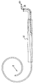
図7は、本発明の一態様によるアンカー1の側面図であって、該アンカーは、胃腸管内に挿入される前の真っ直ぐに伸ばされたポジション(姿勢)となっている。剛性を持ったロッド8が、典型的に、アンカー1の中心コア7の長さ全体に渡って延び、それによって、アンカー1が全体的に真っ直ぐに伸びた形状を呈するようになっている。(代替的には、このリジッドなロッドは、中心コアの長さの一部だけに渡って延びている)。近位端37と遠位端38とを有する押し込み(pushing)カテーテル36が、アンカー1に軸を一線に揃えて示されている。この押し込みカテーテル36は、その全体を貫通して延びる内腔(bore)39を有する。ロッド8が、内腔39の全体を通じて延び、そして、当該押し込みカテーテルの近位端37の外側へと延びる。このリジッドなロッド8は、典型的には、剛性を有し、曲がらない生体適合性材料を有してなり、該押し込みカテーテル内へ容易に滑らせて入れそして出すことができる。代替的には、このリジッドなロッドは、概してはリジッドな生体適合性材料を有してなり、少しは曲がるが、押し込みカテーテル内に滑るように容易に挿入したり出したりするために、十分に剛性を有する。剛性を有するロッド8は、押し込みカテーテル36の内腔39と全面的に係合するように、そして、押し込みカテーテルの遠位端38から外へ約35から55cmだけ、例えば、図1−4を参照しながら上記で説明したC形状の形態のためには、およそ40cm、または、およそ45cm、延びて出るように、充分に長くなっている。ロッド8の遠位部分は、押し込みカテーテル36の遠位端38を越えて延び、アンカー1の中心コア7内へと挿入される。他の配置形態、例えば、図5および6を参照しながら上記で説明したS形状の形態、または、図12A−Bを参照しながら下記で説明するうず巻き状の形態と共に用いられるときは、ロッド8は、これら形態のコアの長さに対して適当な長さを有するようにされる。
【0051】
押し込みタブ40が、好ましくは、押し込みカテーテルの近位端37の近傍に備えられる。タブ40は、内視鏡操作者によって用いられ、ロッド8の近位端を患者の口に対して固定するように保持しながら該タブを前方に押すことによって、アンカー1をロッド8から押して外すために用いられる。この押し込みカテーテルは、典型的には、生体適合性の剛性を有する曲がらない材料、または、概しては剛性を有するが僅かに屈曲可能な材料を有してなる。
【0052】
アンカー1が胃腸管内に挿入され、真っ直ぐに伸ばすロッドが取り外された後、当該アンカーは、その「C」、「S」、「U」、または、該アンカーが呈するように構成されたあらゆる他の予め選択された屈曲形状を呈する。予め選択された屈曲形状を呈することで、当該アンカーは、概しては、挿入されたデバイスがどこかへ移動してしまうことを阻止する。アンカー材料は、配備のために真っ直ぐになり得るよう十分に可撓性を有し、かつ、ロッド8が取り外された後に残留する記憶形状を有する。このようにして、その記憶形状を取った後でさえも、内視鏡を安全に組織に傷を付けることなく取り外すことが容易となる。適当であるように、アンカー1は、取り外しの際に、部分的に、または、完全に真っ直ぐに伸ばされる。アンカー1は、1つ、または、複数のバルーン、送信機、カメラ、または、胃管腔内に設置されることが望まれるあらゆる他のデバイスを担持することを可能にする。
【0053】
アンカー1は、図1−4を参照しながら上記で説明したC−形状になる場合には、典型的には、全長は、約30cmから約55cmの間、例えば、およそ40cmである。中央の、概して真っ直ぐな部分は、典型的には、約15cmから約25cmの間の長さ、例えば、およそ16cm、または、およそ20cmの長さを有し、そして、各端の部分は、典型的には、約8cmから約15cmの間、例えば、そよそ10cm、または、およそ12cmの長さを有する。これらの寸法は、勿論、胃の形状およびサイズによって変えてもよい。胃腸管の他の領域は、様々な形状およびサイズを必要とする。典型的には、アンカー1の遠位端2は、閉じられ、そして、胃腸管内に楽に通すことができるように柔らかく可撓性を有する先端を有するようにテーパーとされる。
【0054】
図8は、本発明の1つの態様による、アンカー1の遠位端2に取り付けられた付属物(appendage)42を示している。付属物42は、また、図5−6を参照しながら上記で説明した(形状は今示している)アンカー22の遠位端2に取り付けられてもよい。付属物42は、可撓性を有するシャフト44内に収容されたワイヤー45を有する。該付属物は、好ましくは、遠位端の先端2の細長い延長物であり、遠位端の先端2と同一の材料から構成される。該付属物は、好ましくは、糸状(string-like)であり、およそ3−5mmの直径とされる。この中に収容されるワイヤー45は、典型的には、単一部品(unitary piece)であり、典型的には、比較的短く比較的可撓性を有する第1のセグメント46(例えば、およそ5cmの長さを有する)を有する。該ワイヤーはこの“糸”状の付属物内を延びているので、より長く比較的堅固なセグメント48(例えば、およそ8−10cmの長さを有する)の後に、第3の可撓性を有するセグメント50(例えば、およそ3cmの長さを有する)が続く。ワイヤー45は、代替的には、各々が様々な長さを有する、可撓性を有するセグメントと、堅固なセグメントとが、交互になった異なる配置構成を有する。
【0055】
バルーン10が収縮した状態にあるときは、付属物42は、典型的には、図8に示したポジションを呈し、付属物42の遠位端52は、アンカー1の近位端4の近傍に位置する(図示の明確さのために、バルーン10は、図8には示されていない。該バルーンは、例えば、図1に収縮した状態にて見ることができる)。このポジションでは、バルーン10が膨張していない場合、付属物42は、デバイスに対して追加的な安全性を提供する。付属物42は、アンカー1の近位端4と遠位端2との間の間隙を閉じ、それによって、デバイスが胃から出て幽門内へと望ましくない移動を起こすことを阻止する。バルーン10が、例えば、図4に示されるように、膨張すると、付属物42は、バルーンによって容易に移動させられる(付属物42の遠位端52が、もはやアンカー1の近位端4の近傍には位置しないように)。
【0056】
図9および10は、本発明のそれぞれの態様に従った、アンカー1に結合されたアタッチメント60を示している。アタッチメント60は、図5−6(構成は示されていない)を参照しながら上記で説明したアンカー22に取り付けられててもよい。アタッチメント60は、1つ、または、複数の要素48を含み、該要素は、例えば、コード、リボン、スポンジ、他の細い材料、または、これらの組み合わせから構成してもよい。要素48は、典型的には、生体適合性材を有してなる。アタッチメント60は、胃の前庭部の全体、または、一部を占拠するように適合していおり、これによって胃内容排出に干渉する。幾つかの用途に対しては、図9に示されているように、アタッチメント60がバルーン10の代わりに用いられる。これらの用途では、アタッチメント60は、例えば、アンカー1の中央部分1に結合されていてもよい。代替的には、幾つかの用途に対しては、図10に示されているように、アタッチメント60は、バルーン10と組み合わせて用いられる。これら用途においては、アタッチメント60は、例えば、アンカー1の横の腕部に結合されてもよい。
【0057】
図11は、本発明の1つの態様に従った、アンカー1に接続されたデバイス70を示している。デバイス70は、送信デバイス、または、他のデバイス(例えば、カメラのようなもの)を有し、別個に配置しても、または、(図11に示されているような)バルーン10といった他のデバイスと組み合わせて配置してもよい。デバイス70は、また、別のタイプの治療用デバイスから構成されても良く、例えば、デバイス50は、薬物を投与するための(administering medication)デバイス、または、腫瘍を標的とするデバイスから構成されてもよい。デバイス70が腫瘍を標的とするデバイスからなる幾つかの用途に対しては、デバイス70は、化学療法、放射線療法、光線力学療法、腫瘍切除療法、シード植込み療法、または、当業者においてよく知られたあらゆる他の抗腫瘍療法を施すように適合化される。
【0058】
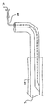
図12Aおよび12Bを参照すると、本発明の1つの態様に従った、アンカー1の構成が示されており、該アンカーは、その遠位端において、うず巻き形状(helix)の曲がった形状を呈している。幾つかの用途に対しては、導通路管14が中心コア7内に配置される。バルーン10は、従来のやり方にて膨張させられる。このうず巻き形状の直径は、典型的には、これが幽門を通過できないような直径、例えば、約4cmから約20cmの間、例えば、約8cmから約14cmの間にされる。デバイスが、当該アンカーの真っ直ぐな長さの部分に結合され、それは、治療用デバイス(例えば、バルーン10);送信デバイス(例えば、カメラ、または、他の送信デバイス);または、他の治療用デバイス70といったものである。幾つかの用途に対しては、当該アンカーの近位端は、湾曲した先端部を有し(例えば、うず巻き形の曲がった形状を呈する)、これが、概しては、非外傷性の(atraumatic)表面を形成することによって、組織の外傷を減少させる。
【0059】
図1−12Bを参照しながら上記で説明したアンカーの近位端2は、典型的には、テーパーにはされず、むしろ、接触した際の組織の損傷を防止するために丸くされる。当該アンカーは、典型的には、およそ7−35Fr口径、例えば、およそ7−20Fr口径、または、およそ25−35Fr口径を有する。幾つかの用途に対しては、当該アンカーの内側表面は、ロッド8の通過が容易になるように、および/または、形状を維持するために、アンカーの残りの部分のそれとは異なる生体適合性材から構成される。別個の案内ワイヤー管12が設けられない用途に対しては、当該アンカーは、典型的には、より小さな口径、例えば、およそ6−16Frを有する。更に代替的には、当該アンカーの中心コア7は、案内ワイヤーのために、または、案内ワイヤー/真っ直ぐに伸ばすロッドの組合せのために用いられる。
【0060】
配備
本発明の態様の使用の以下の例は、本発明の範囲を制限することを意図するものではないことを理解されるべきである。
【0061】
本発明の一態様では、ここで説明された胃腸用デバイスの配備は、胃オーバーチューブを用いて、または、案内ワイヤーを覆って実施される。これらの標準のよく確立された技術が、ここに説明されている新規の方法およびデバイスに対して適合化される。案内ワイヤー法は、上部胃腸管内に導入される場合について食道狭窄症との関連で説明されている。例えば、上述の Kadakia SC 等、Flesischer DE 等、および/または、Dumon JR 等の論文で述べられている技術を、必要におうじて変更を加えて(mutatis mutandis)、食道拡張器を案内ワイヤーにて導入する技術を含めて、蛍光透視を必要とすることなく、用いてもよい。
【0062】
本発明の1つの態様では、ここで説明されているアンカーは、Dumor JR 等によって説明されているサバリ(Savary)システム案内ワイヤー技術を、すぐ下に説明するように修正を加えて用いることで配備される。上部の内視鏡検査が遂行され、食道、胃および十二指腸が完全に評価される。内視鏡操作者は、門歯から胃−食道接合部までの距離を測定する。胃前庭部内に導入された内視鏡を用いて、案内ワイヤーが(可撓性を有する先端を先にして)、直視下にて胃前庭部内へと通される。案内ワイヤーが前方に進められ、内視鏡が取り除かれながら、該案内ワイヤーが胃管腔内に残される。次に、案内ワイヤーの自由端(口の外側)が、アンカーの案内ワイヤー腔内に入れられる。アンカーが、案内ワイヤーを覆いながら(案内ワイヤーの口に対する位置は変わらないようにしながら)下方に向かって滑らされ、そして、口の中を下方に食道に向かって通される。門歯におけるアンカー上の外面のマークが(最初の内視鏡検査の際に内視鏡操作者によって示された)胃−食道接合部のレベルより6−8cm大きくなった時点で、ロッドを患者の口に対して固定するように保持しながら、押し込みカテーテルの押し込みタブが前方に押される。いったん該アンカーがロッドから外れたら、ロッド、案内ワイヤー、および、押し込みカテーテルが取り外される。導通路の膨張ポートは、口の外側にあり続ける。次に、内視鏡が、当該アンカーのポジション(姿勢)を調べるために挿入され、任意の必要な調節が行われる。次に、導通路膨張ポートが、ルアー・ロックシリンジでアクセスされ、胃のサイズに応じて(それは内視鏡にて観察することができる)、およそ400−1000ccの流体にて膨張させられる。当該アンカーが複数のバルーンを含む態様に対しては、これが反復される。次に導通路チューブ(conduit tubing)が、スネアー、フックカテーテル、握り鉗子、または、同等物を用いて、胃の中へと引き下ろされる。該導通路チューブが、いったん胃前庭部内に入ったら、次に内視鏡が取り出され、この手順は完了する。
【0063】
もしも、後になって、バルーンを調節する必要が生じたときは、内視鏡とスネアー、フックカテーテル、握り鉗子、または、同等物を用いて、この導通路チューブの自由端へのアクセスが遂行される。該導通路が口から外へ引っ張られ、膨張、または、収縮が遂行され、その後、該導通路の自由端が、上で説明したように、胃管腔内へと押し入れられる。本出願を読み終えた当業者においては明らかなように、ここで説明されているこれら態様は、挿入するための様々な方法を用いて、胃管腔内に設置することができる。
【0064】
本発明の1つの態様では、ここで説明されたアンカーは、標準的な胃オーバーチューブ法を用いて、すぐ下に説明するような修正を加えて配備される。標準的な内視鏡検査が遂行され、食道、胃および十二指腸が調べられる。次に内視鏡が取り出され、胃オーバーチューブが典型的には通常の技術を用いて設置される。典型的には、上述の Werth 等による文献において説明されているような技術を用いて、胃オーバーチューブが異物の除去および複数の内視鏡挿管のために用いられる。オーバーチューブがいったん所定の位置に設置されると、当該アンカーがこのオーバーチューブを通して設置される。案内ワイヤー技術について上で説明したように、アンカーの遠位端の先端が胃・食道接合部を6−8cmだけ越えると、押し込みカテーテルのタブが押される。当該アンカーがロッドから外れたら、ロッドと押し込みカテーテルが取り出される。次に、上で説明したように、内視鏡がこのオーバーチューブ内に通され得、アンカーのポジションが調べられる。この手順の残りの部分は、上で説明した案内ワイヤー手続きと同一である。
【0065】
このアンカーは、あらかじめ選択された曲がった形状に復帰すると、収縮したバルーンの移動を阻止し、これによって安全な減量デバイスが提供される。当該アンカーは、1つより多くのバルーンを留める(anchor)ために用いることができ、胃管腔内にとどまることを必要とされる任意のデバイスを固定することができる。当該アンカーは、その人の減量が頭打ちとなり、その人がさらなる減量を希望するような肥満手術後の患者に用いることもできる。当該アンカーは、胃腸管内の、任意のタイプのデバイスが所定位置にとどまることを必要となるようなどのような場所にでも用いることができる。当該アンカーの所在地(site)が、予め決定される形状、幾何、およびサイズを決定する。これは、典型的には、外来のセッティングでの、意識のある鎮静作用下において、内視鏡的に取り付けられ、内視鏡的に取り外される。
【0066】
本発明は、当業者においては理解できると思われるが、上記で特に示され説明されたものに制限されるものではない。そして、むしろ、本発明の範囲は、上で説明された様々な特徴の組合せおよびサブの組合せの両方、および、上の説明を読むことで当業者に思いつくような、従来技術には属さない、本発明の変形物および修正物をも含む。
【図面の簡単な説明】
【0067】
【図1】図1は、本発明の一態様に依る、胃腸の浮動的なアンカーの側面図である。
【図2】図2と3は、本発明の一態様に依る、図1のアンカーの他の形態の、それぞれ、側面図と断面図である。
【図3】図2と3は、本発明の一態様に依る、図1のアンカーの他の形態の、それぞれ、側面図と断面図である。
【図4】図4は、本発明の一態様に依る、図2に示される態様の、膨張したバルーンを示す側面図である。
【図5】図5は、本発明の一態様に依る、他の胃腸の浮動的なアンカーの側面図である。
【図6】図6は、本発明の一態様に依る、図5のアンカーの、バルーンを膨張させた状態にて示す側面図である。
【図7】図7は、本発明の一態様に依る、図1のアンカーの一態様を、胃腸管内に挿入される前の、真っ直ぐに伸ばしたポジションにて示す側面図である。
【図8】図8は、本発明の一態様に依る、図1のアンカーの遠位端に取り付けられた付属物を示している。
【図9】図9と10は、本発明の各々の態様に依る、図1のアンカーに結合されたアタッチメントを示している。
【図10】図9と10は、本発明の各々の態様に依る、図1のアンカーに結合されたアタッチメントを示している。
【図11】図11は、本発明の一態様に依る、図1のアンカーに取り付けられたデバイスとバルーンの側面図である。
【図12A】図12Aは、図1のアンカーの一形態の側面図であって、当該アンカーは、本発明の一態様に従って、うず巻き形状の遠位端と中心コア内の導通路管とを有する。
【図12B】図12Bは、本発明の一態様に依る、図12Aに示される構成の近位端の拡大図である。【Technical field】
[0001]
Cross-reference of related applications
This application is a continuation-in-part of US
This application is a US
[0002]
Field of Invention
The present invention relates generally to anchors that can be placed in the gastrointestinal tract. In particular, the present invention is directed to a floating anchor, which can be inserted into and placed in the esophagus, stomach, small intestine, large intestine, or rectal cavity. When it is done, it will return to a bent shape.
[Background]
[0003]
Background of the Invention
Morbid obesity is reported in US S. However, it is still an increasing problem. Various forms of gastric bypass surgery have been developed and improved over the past decades. In recent years, laparoscopic gastric banding has emerged as an option for minimally invasive surgery. However, bariatric surgery suffers from a mortality rate of up to 20%, and the percentage of reoperations 3 to 5 years after surgery approaches 25%. Bariatric surgery has a surgical mortality rate of 0.5%. Dietary and drug alternative approaches are less effective and have a high relapse rate. Today, Bioenterics® Intragastric Balloon (BIB®) (Inamed Corporation, Santa Barbara, California, USA) S. It is also used overseas, achieving an average weight loss of 15 kg and a 5 point reduction in BMI. However, a balloon deflation rate of 8-9% results in undesirable migration and leads to failure.
[0004]
US Patent Application Publication No. 2004/0044357 to Gannoe et al., Which is incorporated herein by reference, describes a device that occupies the stomach space, which is deployed in the gastrointestinal tract of a patient. In particular, it includes a stent configured to be deployed in the esophagus or stomach. Secured to the stent is an inflatable member adapted to stay in the patient's stomach. When the inflatable member is inflated, it occupies a certain volume within the patient, which is further anchored to the deployed stent so that the expandable member is retained or anchored in the stomach. It is anchored. A method and system for deploying the space occupying device is also described.
[0005]
PCT publication WO 05/107641 to Chen et al., US patent application publication 2005/0267596, and US patent application publication 2005/0267595, which are incorporated herein by reference, describe gastric balloons. The balloon has a skeletal structure, one or more internal inflatable chambers within the skeletal structure, and one or more inflatables formed over the chamber filling the space. A floating bag. The gastric balloon is deployed via the esophagus using a gastroscope and inflated in the body, preferably using a combination of liquid and gaseous inflation media.
[0006]
PCT publication WO 05/009288 to Burnett et al. And US patent application publication 2005/0033331, which are hereby incorporated by reference, are intermittent and / or partial pyloric valves. Describes techniques for helping to prevent obstruction. The described device generally includes a support portion for preventing the device from passing through the pyloric valve and a tissue engaging portion for contacting tissue adjacent to the pyloric valve to occlude it. Including. Some aspects further include a positioning member that extends from the tissue engaging portion to assist in positioning the device to occlude the valve. Optionally, a retention member may be included at the distal end of the positioning member to further retain the device in a position in the stomach. Some embodiments can be introduced into the stomach through the esophagus, by swallowing, or through a conduit or catheter. Some aspects have been described as being fully recoverable. Some embodiments are self-expanding in the stomach and others are inflated or inflated.
[0007]
US Patent Application Publication 2005/0055039 to Burnett et al., Which is hereby incorporated by reference, describes a device for performing one or more functions in the gastrointestinal tract of a patient. The device includes an anchoring member and at least one actuator, sensor, or a combination of both coupled to the anchoring device. The anchoring device is adapted to maintain at least a portion of the device within the pyloric portion of the patient's stomach and to intermittently engage the stomach tissue without direct attachment. The actuator performs any suitable function, such as transferring energy to tissue, acting as a sleeve to reduce nutrient absorption, space occupancy in the stomach, drug elution, and other similar functions. The sensor may be any suitable patient characteristic within the patient's gastrointestinal tract, such as pH, temperature, bile content, nutrients, lipids, sugars, alcohol, opiates, drugs, analytes, electrolytes, and / or hemoglobin, etc. Adapted to detect.
[0008]
The following patents and patent application publications, which are hereby incorporated by reference, will be important.
US Patent Application Publication No. 2005/0228504 to Demarais
US Patent Application Publication 2005/0085923 to Levine et al.
US Patent Application Publication 2005/0192614 to Binmoeller
US Patent Application Publication No. 2004/0267378 to Gazi et al.
US Patent 4,416,267 to Garren et al.
US Patent 5,052,998 to Zimmon
PCT Publication WO05 / 039457 to Paganon et al.
PCT Gazette to Paganon WO 04/089292
Canadian Patent Application Publication No. 2482335 to Byrum et al.
US Patent Application Publication 2005/0070937 to Jambor et al.
US Patent Application Publication 2005/004430 to Lee et al.
PCT Gazette WO04 / 105622 to Ritchie
US Patent Application Publication No. 2004/088008 to Gannoe et al.
PCT publication WO 04/014237 to Gannoe et al.
US Patent Application Publication No. 2004/093091 to Gannoe et al.
US Patent Application Publication No. 2004/059289 to Garza et al.
PCT Gazette to Alverdy WO 03/095015
European Patent Application Publication EP1342458 to Creusy et al.
US Patent Application Publication 2003/158869 to Wazne
PCT publication WO03 / 055420 to Lointier et al.
US Patent 6,656,194 to Gannoe et al.
US Patent Application Publication 2003/171768 to McGhan
PCT publication WO02 / 40081 to Bales et al.
PCT Publication WO01 / 66166 to Birk
PCT Publication WO98 / 56321 to Pier et al.
US Patent 5,234,454 to Bangs
Canadian Patent Application Publication CA2068715 to Kuzmak
US Patent 4,696,288 to Kuzmak et al.
US Patent 5,129,915 to Cantenys
US Patent 5,084,061 to Gau et al.
US Patent 4,908,011 to Jacobsen et al.
European Patent Application Publication EP 0246999 to Eshel et al.
PCT publication WO87 / 00034 to Taylor
US Patent 4,739,758 to Lai et al.
PCT Publication WO86 / 06611 to Kullas et al.
US Patent 4,694,827 to Weiner et al.
German patent application DE 3540936 to Stricker et al.
GB 2139902 GB Patent Application Publication to Celestin et al.
Canadian Patent Application Publication CA12333387 to Garren et al.
US Patent 4,899,747 to Garren
German Patent Application DE 3326061 to Woerner
German patent application DE 3310234 to Husfeldt
Italian patent IT1235492 to Frimberger et al.
US Patent 4,485,805 issued to Foster
German Patent Application Publication No. DE3227585 to Woerner
US Patent 4,416,267 to Garren et al.
US Patent 4,315,509 to Smit
[0009]
The following documents, which are incorporated herein by reference, will be important.
Kadakia SC et al., “Esophageal dilation with polyvinyl bougies using a marked guidewire without the aid of fluoroscopy”, Am J Gastro 88: 1381-86 (1993)
Fleischer DE et al., "A marked guidewire facilitates esophageal dilation", Am J Gastro 84: 359-61 (1989)
Dumon JR et al., "A new method of esophageal dilation using Savary-Gilliard bougies", Gastro Endosc 31: 379-82 (1985)
Werth et al., “A safe and quick method for endoscopic retrieval of multiple gastric foreign bodies using a protective sheath”, Surg Gynecol Obstet 171 (5): 419-20 (1990)
DISCLOSURE OF THE INVENTION
[0010]
Summary of the Invention
In accordance with one aspect of the present invention, a flexible tubular anchor with elastic memory to assume a preselected bent form is described for placement in the gastrointestinal tract. The anchor has a central core having a distal end and an open proximal end and extending toward the distal end. When the core receives a straight extending rod therethrough, the anchor is extended straight from a preselected bent configuration.
[0011]
In accordance with another aspect of the present invention, a method for inserting a flexible tubular anchor into a patient's gastrointestinal tract is described. The anchor has a resilient memory to assume a preselected bent configuration, has a distal end and an open proximal end, has a central core extending toward the distal end, and a balloon is Sealed along a portion of the anchor, the inflation conduit extends from the proximal end toward the interior of the balloon, and the pusher catheter has a lumen therethrough that is axially connected to the anchor. A rod that is aligned and straight out extends through the catheter and anchor. The method generally includes inserting the anchor into a patient's stomach in its straightened form, and separating the anchor from a straight extending rod, whereby the anchor Having a preselected bent shape, and then inflating the balloon.
[0012]
As will be appreciated by those skilled in the art, a feature provided by some aspects of the present invention is the ease with which an anchor is inserted into the gastrointestinal system. Another feature provided by some aspects of the present invention is the safety and security provided by the use of such anchors. Accordingly, one object of some aspects of the present invention is to provide a safe and easy method for inserting and securing a floating anchor in the gastrointestinal system, thereby allowing various devices to be safely placed in the gastrointestinal tract. It is to be able to fix. Another object of some aspects of the invention is to secure the balloon safely and securely in the stomach to promote a feeling of fullness in the patient. Additional objects of some aspects of the invention will become apparent upon reading the following description.
[0013]
Thus, according to one aspect of the present invention, there is provided a device for use in the gastrointestinal tract of a subject, the device comprising:
Including a straight rod,
A tubular anchor having flexibility, the tubular anchor having a distal end and an open proximal end, and sized to fit within the gastrointestinal tract; The elastic memory biases the anchor toward the pre-selected bent form, the anchor from the open proximal end Shaped to define a central core extending toward the distal end, and the anchor is straightened from a preselected bent configuration by insertion of a straightening rod into the central core Configured,
Including a device coupled to the anchor, the device being selected from a list consisting of a therapeutic device and a transmitting device.
[0014]
For some applications, the distal end of the anchor is tapered. For some applications, the bent form is a C-shaped form, an S-shaped form, a U-shaped form, Vortex Selected from the group consisting of a wound form and a sinusoidal form, and the material has an elastic memory that biases the anchor to said It is directed to the direction of the selected bent form.
[0015]
For some applications, the device includes a pusher catheter that is shaped to define a lumen therethrough, the catheter being axially aligned with the anchor. A rod that is adapted to line up and extends straight is configured to be inserted through the catheter and into the central core of the anchor.
[0016]
In one aspect, the anchor is shaped to define a wall having a guide wire tube therein.
[0017]
In one aspect, the device includes a transmitting device.
[0018]
In one aspect, the anchor is adapted to interfere with the subject's gastric emptying.
[0019]
In one aspect, the device includes a therapeutic device. For some applications, the therapeutic device includes a thread-like attachment. For some aspects, the therapeutic device includes a drug delivery device. For some applications, the therapeutic device is adapted to deliver tumor targeted therapy.
[0020]
In one aspect, the therapeutic device comprises an attachment that is adapted to interfere with gastric emptying of the subject's stomach when the anchor is placed in the stomach. It is a thing.
[0021]
In one aspect, the therapeutic device includes a balloon coupled to the balloon coupling portion of the anchor. For some applications, the anchor includes a conduit that is wrapped around the outer surface of the anchor, the conduit extending from the proximal end of the anchor into the interior of the balloon.
[0022]
In one aspect, the balloon is adapted to promote a feeling of fullness in the subject. Alternatively or additionally, the balloon is adapted to interfere with the subject's peristaltic wave and gastric emptying.
[0023]
For some applications, the balloon includes a first balloon and the therapeutic device includes a second balloon.
[0024]
In one aspect, a balloon is disposed around the balloon coupling portion of the anchor. For some applications, the anchor includes a proximal portion and a distal portion, the proximal portion and the distal portion being on each side of the balloon coupling portion, the balloon comprising a balloon coupling portion. And is not connected to either the proximal portion or the distal portion. For some applications, the length of the anchor balloon coupling portion is less than 75% of the total length of the anchor, such as less than 50% of the total length of the anchor.
[0025]
In one aspect, the anchor is shaped to define a conduit channel that extends from the proximal end of the anchor into the interior of the balloon. For some applications, the device has a conduit having a distal end and a proximal end, the conduit being adapted to be disposed through the conduit channel; The distal end opens to the inside of the balloon and the proximal end opens to the outside of the anchor.
[0026]
In one aspect, the distal portion of the anchor has a curved shape when the anchor assumes a bent configuration. For some applications, when the anchor assumes a bent configuration, the distal portion of the anchor Vortex It has a wound shape. For some applications, when the anchor assumes a bent configuration, the proximal portion of the anchor is Vortex It has a wound shape.
[0027]
In one aspect, when the anchor assumes a bent configuration, the proximal portion of the anchor has a curved shape. For some applications, when the anchor assumes a bent configuration, the proximal portion of the anchor is Vortex It has a wound shape.
[0028]
In one aspect, the anchor has an elongated appendage extending from its distal end, the appendage having a distal end, the appendage when the anchor assumes a bent configuration. , And configured to assume a position such that the distal end of the appendage is near the proximal end of the anchor. For some applications, the appendage includes a housing and a wire therein, the wire including a first flexible segment, a second relatively rigid segment, and a first 3 relatively flexible segments. For some applications, the device includes a balloon coupled to an anchor and the appendage is adapted to be moved by the balloon when the balloon is inflated, the appendage So that its distal end is no longer near the proximal end of the anchor.
[0029]
According to one aspect of the present invention, there is further provided a device for use in the gastrointestinal tract of a subject, the device comprising:
Including a straight rod, and
A tubular anchor having flexibility, the tubular anchor having a closed distal end and an open proximal end, and sized to fit within the gastrointestinal tract; The elastic memory biases the anchor toward the pre-selected bent form, the anchor being open Shaped to define a central core extending from the distal end toward the distal end, and the anchor is straightened from a preselected bent configuration by insertion of a straightly extending rod into the central core. It is configured to be.
[0030]
According to one aspect of the present invention, there is further provided a device for use in the stomach of a subject, the device comprising:
An elongated biocompatible anchor, the anchor having a proximal portion, a distal portion, and a balloon coupling portion therebetween, the anchor being sized to fit within the stomach And
Including a balloon, which is coupled to the balloon coupling portion of the anchor and not to the proximal or distal portion.
[0031]
In one aspect, the balloon is adapted to promote a feeling of fullness in the subject. Alternatively or additionally, the balloon is adapted to interfere with the subject's peristaltic waves and gastric emptying.
[0032]
In one aspect, the anchor is adapted to interfere with the subject's gastric emptying.
[0033]
In one aspect, the anchor is adapted to assume a preselected bent configuration when in the stomach.
[0034]
In one aspect, the balloon is located around the balloon coupling portion of the anchor. For some applications, the length of the anchor balloon coupling portion is less than 75% of the total length of the anchor, such as less than 50% of the total length of the anchor.
[0035]
According to one aspect of the present invention, a method is further provided, the method comprising:
Straightening a flexible tubular anchor, the anchor comprising a material with elastic memory, the elastic memory biasing the anchor and pre-selected bending The anchor is straightened by inserting a straight-extending rod into the central core extending from the open proximal end to the distal end of the anchor. And
Inserting a straightly stretched anchor, together with a rod therein, into the gastrointestinal tract of the subject,
Removing the anchor from the rod, thereby allowing the anchor to assume a preselected bent configuration.
[0036]
For some applications, inserting a straightened anchor includes passing the anchor over a guide wire. Alternatively, inserting a straight stretched anchor includes inserting the anchor into the overtube.
[0037]
For some applications, inserting the rod into the central core inserts the rod through the lumen of the pusher catheter that is axially aligned with the anchor and then into the central core. And removing the rod from the anchor includes pushing the anchor away from the rod by pushing the pushing catheter.
[0038]
For some applications, inflating the balloon includes inserting an inflation conduit into the gastrointestinal tract and inflating the balloon through the inflation conduit. For some applications, inflating the balloon includes inflating the balloon through an inflation conduit that passes through the conduit channel.
[0039]
According to one aspect of the invention, in addition, a method is provided, the method comprising:
Inserting an elongate anchor having a proximal portion, a distal portion, and a balloon coupling portion therebetween, in the stomach of the subject;
Inflating a balloon coupled to the balloon coupling portion of the anchor and not coupled to the proximal or distal portion.
[0040]
The method and apparatus of the present invention may be better understood with reference to the following detailed description of specific embodiments and the accompanying drawings, which illustrate and illustrate the embodiments thereof.
BEST MODE FOR CARRYING OUT THE INVENTION
[0041]
Detailed description of the embodiment
The following preferred embodiments, illustrated by the drawings, are illustrative only to illustrate the present invention and are not intended to limit the invention as encompassed by the claims of the invention.
[0042]
As shown generally in the drawings, a gastrointestinal floating
[0043]
FIG. 1 shows a gastrointestinal floating
[0044]
For some applications, a
[0045]
2 and 3 are a side view and a cross-sectional view, respectively, of another configuration of the
[0046]
FIG. 4 shows the
[0047]
The diameter of the conduit and its lumen (lumen) is typically sufficient to inflate any balloon. The conduit is constructed of a biocompatible material that can withstand an acidic environment and bend with its anchor into its different conformation. The balloon is inflated to a volume sufficient to fill or partially fill the gastric lumen, typically between about 400 cc and about 1000 cc, depending on the size of the stomach. The anchor typically has markings on the outer surface from its tapered tip end, for example, at 5 cm intervals, to help guide the operator.
[0048]
FIG. 5 illustrates an
[0049]
FIG. 6 shows the anchor of FIG. 5 with the proximal and distal balloons inflated.
[0050]
FIG. 7 is a side view of the
[0051]
A
[0052]
After the
[0053]
When the
[0054]
FIG. 8 illustrates an appendage 42 attached to the
[0055]
When the
[0056]
Figures 9 and 10 show an
[0057]
FIG. 11 illustrates a
[0058]
Referring to FIGS. 12A and 12B, there is shown the configuration of
[0059]
The
[0060]
deployment
It should be understood that the following examples of use of aspects of the invention are not intended to limit the scope of the invention.
[0061]
In one aspect of the invention, deployment of the gastrointestinal device described herein is performed using a gastric overtube or over a guide wire. The well-established techniques of these standards are adapted for the new methods and devices described herein. The guide wire method has been described in the context of esophageal stenosis when introduced into the upper gastrointestinal tract. For example, the techniques described in the papers mentioned above, such as Kadakia SC, Flesischer DE, etc. and / or Dumon JR, etc., may be modified as necessary (mutatis mutandis) to guide the esophageal dilator with a guide wire. It may be used without requiring fluoroscopy, including the technology to be introduced.
[0062]
In one aspect of the present invention, the anchor described herein is deployed using the Savary system guidewire technology described by Dumor JR et al., With modifications as described immediately below. Is done. Upper endoscopy is performed and the esophagus, stomach and duodenum are fully evaluated. The endoscope operator measures the distance from the incisor to the stomach-esophageal junction. Using an endoscope introduced into the gastric vestibule, a guide wire (with the flexible tip first) is passed through the gastric vestibule under direct viewing. As the guide wire is advanced forward and the endoscope is removed, the guide wire is left in the gastric lumen. The free end of the guide wire (outside the mouth) is then placed in the guide wire cavity of the anchor. An anchor is slid down while covering the guide wire (while keeping the position of the guide wire relative to the mouth) and is passed down the mouth towards the esophagus. When the external marking on the anchor in the incisor is 6-8 cm above the level of the gastro-esophageal junction (shown by the endoscopic operator during the first endoscopy), the rod is The pusher tab of the pusher catheter is pushed forward while holding it fixed against the mouth. Once the anchor is released from the rod, the rod, guide wire, and pusher catheter are removed. The expansion port of the conduction path remains outside the mouth. Next, an endoscope is inserted to check the position (posture) of the anchor and any necessary adjustments are made. The conduit inflation port is then accessed with a luer lock syringe and inflated with approximately 400-1000 cc of fluid, depending on the size of the stomach (which can be viewed with an endoscope). This is repeated for embodiments where the anchor includes multiple balloons. The conduit tubing is then pulled down into the stomach using a snare, hook catheter, grasping forceps, or the like. Once the conduit tube has entered the gastric vestibule, the endoscope is then removed and the procedure is complete.
[0063]
If it is later necessary to adjust the balloon, access to the free end of the conduit tube is performed using an endoscope and snare, hook catheter, grasping forceps, or the like. The The conduit is pulled out of the mouth and inflation or contraction is performed, after which the free end of the conduit is pushed into the gastric lumen as described above. As will be apparent to those skilled in the art after reading this application, the embodiments described herein can be placed in the gastric lumen using various methods for insertion.
[0064]
In one aspect of the invention, the anchor described herein is deployed using standard gastric overtube techniques with modifications as described immediately below. Standard endoscopy is performed and the esophagus, stomach and duodenum are examined. The endoscope is then removed and a gastric overtube is typically placed using conventional techniques. Typically, gastric overtubes are used for foreign body removal and multiple endoscopic intubations using techniques such as those described in the above-mentioned Werth et al. Once the overtube is installed in place, the anchor is installed through the overtube. As described above for guidewire technology, the pusher catheter tab is pushed when the distal tip of the anchor exceeds the stomach-esophageal junction by 6-8 cm. When the anchor is disengaged from the rod, the rod and pusher catheter are removed. Next, as explained above, an endoscope can be passed through this overtube and the position of the anchor is examined. The rest of this procedure is the same as the guide wire procedure described above.
[0065]
When the anchor returns to the pre-selected bent shape, it prevents movement of the deflated balloon, thereby providing a safe weight loss device. The anchor can be used to anchor more than one balloon and can secure any device that needs to remain in the gastric lumen. The anchor can also be used in patients after bariatric surgery where the person's weight loss has peaked and the person desires further weight loss. The anchor can be used anywhere in the gastrointestinal tract where any type of device needs to remain in place. The anchor site determines the predetermined shape, geometry, and size. This is typically endoscopically attached and removed endoscopically under conscious sedation in an outpatient setting.
[0066]
The present invention will be understood by those skilled in the art, but is not limited to what has been particularly shown and described above. And, rather, the scope of the present invention does not belong to the prior art, as would occur to one skilled in the art upon reading both the various feature combinations and sub-combinations described above, and the above description, Variations and modifications of the invention are also included.
[Brief description of the drawings]
[0067]
FIG. 1 is a side view of a gastrointestinal floating anchor in accordance with an aspect of the present invention.
2 and 3 are a side view and a cross-sectional view, respectively, of another form of the anchor of FIG. 1 in accordance with an aspect of the present invention.
FIGS. 2 and 3 are a side view and a cross-sectional view, respectively, of another form of the anchor of FIG. 1 in accordance with an aspect of the present invention.
FIG. 4 is a side view of an inflated balloon of the embodiment shown in FIG. 2 according to one embodiment of the present invention.
FIG. 5 is a side view of another gastrointestinal floating anchor in accordance with an aspect of the present invention.
FIG. 6 is a side view of the anchor of FIG. 5 shown in a balloon inflated state according to one aspect of the present invention.
FIG. 7 is a side view of one embodiment of the anchor of FIG. 1 in a straightened position prior to insertion into the gastrointestinal tract, according to one embodiment of the present invention.
FIG. 8 illustrates an appendage attached to the distal end of the anchor of FIG. 1 in accordance with an aspect of the present invention.
FIGS. 9 and 10 illustrate attachments coupled to the anchor of FIG. 1 in accordance with each aspect of the present invention.
FIGS. 9 and 10 illustrate attachments coupled to the anchor of FIG. 1 in accordance with each aspect of the present invention.
FIG. 11 is a side view of a device and balloon attached to the anchor of FIG. 1 in accordance with an aspect of the present invention.
12A is a side view of one form of the anchor of FIG. 1, wherein the anchor is in accordance with an aspect of the present invention. Vortex It has a wound distal end and a conduit tube in the central core.
FIG. 12B is an enlarged view of the proximal end of the configuration shown in FIG. 12A, according to one aspect of the invention.
Claims (15)
真っ直ぐに伸ばすロッドを有し、
可撓性を有する管状アンカーを有し、該管状アンカーは、遠位端と開口した近位端とを有し、かつ、胃腸管内に合うサイズとされており、該アンカーは、弾性的な記憶を持った材料を有してなり、その弾性的な記憶が該アンカーにバイアスをかけて予め選択された湾曲した形態を呈する方へと向かわせるものであり、該アンカーは、開口した近位端から遠位端に向かって延びる中心コアを定めるような形状とされ、かつ、該アンカーは、中心コア内への真っ直ぐに伸ばすロッドの挿入によって、予め選択された湾曲した形態から真っ直ぐに伸ばされるように構成されており、
該アンカーの一部分に結合された治療用デバイスを有し、該治療用デバイスはバルーンを有している、
前記装置。A device for use in the gastrointestinal tract of a subject, the device comprising:
It has a rod that extends straight,
A tubular anchor having flexibility, the tubular anchor having a distal end and an open proximal end and sized to fit within the gastrointestinal tract; the material will have a having its elastic memory is intended to direct toward exhibiting a form that it curved preselected bias the said anchor, said anchor, the opened near It is from proximal end shaped so as to define a central core extending toward the distal end, and the anchor is by straightening insert the rod into the central core, straight from preselected curved to form Configured to be stretched to
Has a therapeutic device coupled to a portion of the anchor, the therapeutic device that has a balloon,
Said device.
C形になっている形態と、S形になっている形態と、正弦波の形の形態と、A form that is C-shaped, a form that is S-shaped, a form that is a sine wave,
からなる群から選択されるものである、請求項1記載の装置。The apparatus of claim 1, wherein the apparatus is selected from the group consisting of:
Applications Claiming Priority (5)
| Application Number | Priority Date | Filing Date | Title |
|---|---|---|---|
| US63984304P | 2004-12-27 | 2004-12-27 | |
| US60/639,843 | 2004-12-27 | ||
| US11/132,855 | 2005-05-18 | ||
| US11/132,855 US20060142731A1 (en) | 2004-12-27 | 2005-05-18 | Floating gastro-intestinal anchor |
| PCT/IL2005/001381 WO2006070361A2 (en) | 2004-12-27 | 2005-12-27 | Floating gastrointestinal anchor |
Publications (3)
| Publication Number | Publication Date |
|---|---|
| JP2008526290A JP2008526290A (en) | 2008-07-24 |
| JP2008526290A5 JP2008526290A5 (en) | 2009-02-19 |
| JP4832448B2 true JP4832448B2 (en) | 2011-12-07 |
Family
ID=36612759
Family Applications (1)
| Application Number | Title | Priority Date | Filing Date |
|---|---|---|---|
| JP2007548959A Active JP4832448B2 (en) | 2004-12-27 | 2005-12-27 | Gastrointestinal floating anchor |
Country Status (5)
| Country | Link |
|---|---|
| US (1) | US20060142731A1 (en) |
| EP (1) | EP1830916A2 (en) |
| JP (1) | JP4832448B2 (en) |
| CN (1) | CN101443071B (en) |
| WO (1) | WO2006070361A2 (en) |
Families Citing this family (29)
| Publication number | Priority date | Publication date | Assignee | Title |
|---|---|---|---|---|
| US8403952B2 (en) * | 2004-12-27 | 2013-03-26 | Spatz-Fgia, Inc. | Floating gastrointestinal anchor |
| US9974680B2 (en) | 2004-12-27 | 2018-05-22 | Spatz Fgia, Inc. | System and methods for internalization of external components of adjustable intragastric balloon |
| WO2014082044A1 (en) | 2012-11-26 | 2014-05-30 | Spatz Fgia, Inc. | System and methods for internalization of components of an adjustable intragastric balloon |
| JP2009531122A (en) * | 2006-03-28 | 2009-09-03 | スパツフジア インコーポレイティド | Floating gastrointestinal anchor |
| US20080086082A1 (en) * | 2006-10-06 | 2008-04-10 | Brooks Jeffrey S | Radiopaque marking to detect balloon deflation |
| WO2008121409A1 (en) * | 2007-03-29 | 2008-10-09 | Jaime Vargas | Intragastric implant devices |
| US20100121371A1 (en) * | 2007-04-30 | 2010-05-13 | Spatz Fgia, Inc. | Non-endoscopic insertion and removal of a device |
| US20090192541A1 (en) * | 2008-01-28 | 2009-07-30 | Ethicon Endo-Surgery, Inc. | Methods and devices for predicting performance of a gastric restriction system |
| US20100114148A1 (en) * | 2008-10-30 | 2010-05-06 | Albrecht Thomas E | Devices and methods for adjusting a satiation and satiety-inducing implanted device |
| US20100114144A1 (en) * | 2008-10-30 | 2010-05-06 | Albrecht Thomas E | Intra-gastric satiety creation device with data handling devices and methods |
| US20100114146A1 (en) * | 2008-10-30 | 2010-05-06 | Albrecht Thomas E | Methods and devices for predicting intra-gastric satiety and satiation creation device system performance |
| US20100114141A1 (en) * | 2008-10-30 | 2010-05-06 | Albrecht Thomas E | Optimizing the operation of an intra-gastric satiety creation device |
| US20100114143A1 (en) * | 2008-10-30 | 2010-05-06 | Albrecht Thomas E | Wearable elements for intra-gastric satiety creations systems |
| US8414559B2 (en) | 2009-05-07 | 2013-04-09 | Rainbow Medical Ltd. | Gastroretentive duodenal pill |
| US20110066175A1 (en) * | 2009-05-07 | 2011-03-17 | Rainbow Medical Ltd. | Gastric anchor |
| US20110092998A1 (en) * | 2009-10-13 | 2011-04-21 | Spatz Fgia, Inc. | Balloon hydraulic and gaseous expansion system |
| EP2552350A1 (en) | 2010-03-26 | 2013-02-06 | Ibis Medical Inc. | Intragastric implant devices |
| US8628554B2 (en) | 2010-06-13 | 2014-01-14 | Virender K. Sharma | Intragastric device for treating obesity |
| US9526648B2 (en) | 2010-06-13 | 2016-12-27 | Synerz Medical, Inc. | Intragastric device for treating obesity |
| US10420665B2 (en) | 2010-06-13 | 2019-09-24 | W. L. Gore & Associates, Inc. | Intragastric device for treating obesity |
| US10010439B2 (en) | 2010-06-13 | 2018-07-03 | Synerz Medical, Inc. | Intragastric device for treating obesity |
| AU2012316159A1 (en) | 2011-09-27 | 2014-04-17 | IBIS Medical, Inc. | Intragastric implant devices |
| CN104582645B (en) | 2012-07-13 | 2017-04-05 | Gi动力公司 | TP grappling |
| WO2014098880A1 (en) * | 2012-12-20 | 2014-06-26 | Empire Technology Development, Llc | Inflatable balloon for protecting blood vessel |
| US9492396B2 (en) | 2014-07-15 | 2016-11-15 | Yossi Gross | Enhanced drug delivery pill |
| US10779980B2 (en) | 2016-04-27 | 2020-09-22 | Synerz Medical, Inc. | Intragastric device for treating obesity |
| EP3579910A4 (en) | 2017-02-09 | 2020-12-30 | Spatz Fgia Ltd | Check valve with docking station for gastrointestinal balloon |
| US10675248B2 (en) | 2018-08-14 | 2020-06-09 | Alma Therapeutics Ltd. | Expandable pill |
| EP3897474A4 (en) | 2018-12-21 | 2023-01-04 | Spatz Fgia Ltd | Valve with docking station for gastrointestinal balloon |
Citations (2)
| Publication number | Priority date | Publication date | Assignee | Title |
|---|---|---|---|---|
| US6746460B2 (en) * | 2002-08-07 | 2004-06-08 | Satiety, Inc. | Intra-gastric fastening devices |
| JP2008517677A (en) * | 2004-10-26 | 2008-05-29 | バロノヴァ,インク. | Medical device delivery catheter |
Family Cites Families (51)
| Publication number | Priority date | Publication date | Assignee | Title |
|---|---|---|---|---|
| US4102342A (en) * | 1975-12-29 | 1978-07-25 | Taichiro Akiyama | Valved device |
| US4315509A (en) * | 1977-01-10 | 1982-02-16 | Smit Julie A | Insertion and removal catheters and intestinal tubes for restricting absorption |
| US4416267A (en) * | 1981-12-10 | 1983-11-22 | Garren Lloyd R | Method and apparatus for treating obesity |
| US4899747A (en) * | 1981-12-10 | 1990-02-13 | Garren Lloyd R | Method and appartus for treating obesity |
| US4485805A (en) * | 1982-08-24 | 1984-12-04 | Gunther Pacific Limited Of Hong Kong | Weight loss device and method |
| US4598699A (en) * | 1985-06-10 | 1986-07-08 | Garren Lloyd R | Endoscopic instrument for removing stomach insert |
| US4696288A (en) * | 1985-08-14 | 1987-09-29 | Kuzmak Lubomyr I | Calibrating apparatus and method of using same for gastric banding surgery |
| US4694827A (en) * | 1986-01-14 | 1987-09-22 | Weiner Brian C | Inflatable gastric device for treating obesity and method of using the same |
| GB8603099D0 (en) * | 1986-02-07 | 1986-03-12 | Blass K G | Gastrointestinal module |
| US4739758A (en) * | 1986-05-19 | 1988-04-26 | Criticare Systems, Inc. | Apparatus for stomach cavity reduction |
| DK155637C (en) * | 1986-05-22 | 1989-09-18 | Ballobes Aps | PROCEDURE AND APPARATUS FOR PERFORMING A PUNKING WORK ON A PATIENT IMPLANTED, PUMPED BALLON OR BALLON-LIKE ITEM |
| US4738667A (en) * | 1986-11-04 | 1988-04-19 | Galloway Niall T M | Preformed catheter assembly |
| US5084061A (en) * | 1987-09-25 | 1992-01-28 | Gau Fred C | Intragastric balloon with improved valve locating means |
| EP0379530B1 (en) * | 1988-07-05 | 1992-07-08 | José CANTENYS | Intragastric balloon |
| US4925446A (en) * | 1988-07-06 | 1990-05-15 | Transpharm Group Inc. | Removable inflatable intragastrointestinal device for delivering beneficial agents |
| US5052998A (en) * | 1990-04-04 | 1991-10-01 | Zimmon David S | Indwelling stent and method of use |
| US5234454A (en) * | 1991-08-05 | 1993-08-10 | Akron City Hospital | Percutaneous intragastric balloon catheter and method for controlling body weight therewith |
| US5433216A (en) * | 1993-06-14 | 1995-07-18 | Mountpelier Investments, S.A. | Intra-abdominal pressure measurement apparatus and method |
| US5578048A (en) * | 1993-09-15 | 1996-11-26 | United States Surgical Corporation | Manipulator apparatus |
| US5545209A (en) * | 1993-09-30 | 1996-08-13 | Texas Petrodet, Inc. | Controlled deployment of a medical device |
| US6245040B1 (en) * | 1994-01-14 | 2001-06-12 | Cordis Corporation | Perfusion balloon brace and method of use |
| US6743198B1 (en) * | 1995-03-20 | 2004-06-01 | Conticare Medical, Inc. | Self-cleansing bladder drainage device |
| US6364868B1 (en) * | 1995-08-02 | 2002-04-02 | The Trustees Of Columbia University In The City Of New York | Ureteral catheter and tissue expander and method of megaureter creation |
| US5732715A (en) * | 1996-06-25 | 1998-03-31 | Safe-T-Gard Corporation | Mouthpiece |
| US6183461B1 (en) * | 1998-03-11 | 2001-02-06 | Situs Corporation | Method for delivering a medication |
| US20050192629A1 (en) * | 1999-06-25 | 2005-09-01 | Usgi Medical Inc. | Methods and apparatus for creating and regulating a gastric stoma |
| FR2805986B1 (en) * | 2000-03-13 | 2002-10-11 | Districlass Madical | INTRA-GASTRIC DEVICE WITH VARIABLE VOLUME |
| US7033373B2 (en) * | 2000-11-03 | 2006-04-25 | Satiety, Inc. | Method and device for use in minimally invasive placement of space-occupying intragastric devices |
| CN2465734Y (en) * | 2001-02-22 | 2001-12-19 | 王启斌 | Multifunctional gastrointestinal tube |
| US6589228B2 (en) * | 2001-04-13 | 2003-07-08 | Asher Holzer | Device for aiding urination and method of use thereof |
| US7146984B2 (en) * | 2002-04-08 | 2006-12-12 | Synecor, Llc | Method and apparatus for modifying the exit orifice of a satiation pouch |
| US7033384B2 (en) * | 2002-08-30 | 2006-04-25 | Satiety, Inc. | Stented anchoring of gastric space-occupying devices |
| US8070743B2 (en) * | 2002-11-01 | 2011-12-06 | Valentx, Inc. | Devices and methods for attaching an endolumenal gastrointestinal implant |
| US9060844B2 (en) * | 2002-11-01 | 2015-06-23 | Valentx, Inc. | Apparatus and methods for treatment of morbid obesity |
| IL152630A (en) * | 2002-11-04 | 2010-11-30 | Innoventions Ltd | Implantable device |
| IL152629A (en) * | 2002-11-04 | 2010-12-30 | Innoventions Ltd | Implantable medical device for controlled release of a substance |
| US6656194B1 (en) * | 2002-11-05 | 2003-12-02 | Satiety, Inc. | Magnetic anchoring devices |
| US7291160B2 (en) * | 2003-03-17 | 2007-11-06 | Delegge Rebecca | Intragastric catheter |
| US7357818B2 (en) * | 2003-03-26 | 2008-04-15 | Boston Scientific Scimed, Inc. | Self-retaining stent |
| BR0302240B8 (en) * | 2003-06-24 | 2013-02-19 | semi-stationary balloon in the gastric antrum with anchor rod for weight loss induction in humans. | |
| US20090259236A2 (en) * | 2003-07-28 | 2009-10-15 | Baronova, Inc. | Gastric retaining devices and methods |
| US8048169B2 (en) * | 2003-07-28 | 2011-11-01 | Baronova, Inc. | Pyloric valve obstructing devices and methods |
| US9498366B2 (en) * | 2003-07-28 | 2016-11-22 | Baronova, Inc. | Devices and methods for pyloric anchoring |
| WO2005060882A1 (en) * | 2003-12-09 | 2005-07-07 | Gi Dynamics, Inc. | Apparatus to be anchored within the gastrointestinal tract and anchoring method |
| US7931693B2 (en) * | 2004-02-26 | 2011-04-26 | Endosphere, Inc. | Method and apparatus for reducing obesity |
| US20050267596A1 (en) * | 2004-05-03 | 2005-12-01 | Fulfillium, Inc. A Delaware Corporation | Devices and systems for gastric volume control |
| JP2008500110A (en) * | 2004-05-25 | 2008-01-10 | ユー.エス. エンドスコピー グループ, インコーポレイテッド | Delivery device |
| US9345604B2 (en) * | 2005-05-02 | 2016-05-24 | Almuhannad Alfrhan | Percutaneous intragastric balloon device and method |
| US8216266B2 (en) * | 2005-06-16 | 2012-07-10 | Hively Robert L | Gastric bariatric apparatus with selective inflation and safety features |
| US20070088380A1 (en) * | 2005-10-14 | 2007-04-19 | Endocross Ltd. | Balloon catheter system for treating vascular occlusions |
| US20070100369A1 (en) * | 2005-10-31 | 2007-05-03 | Cragg Andrew H | Intragastric space filler |
-
2005
- 2005-05-18 US US11/132,855 patent/US20060142731A1/en not_active Abandoned
- 2005-12-27 JP JP2007548959A patent/JP4832448B2/en active Active
- 2005-12-27 CN CN2005800486926A patent/CN101443071B/en active Active
- 2005-12-27 EP EP05819222A patent/EP1830916A2/en not_active Withdrawn
- 2005-12-27 WO PCT/IL2005/001381 patent/WO2006070361A2/en active Application Filing
Patent Citations (2)
| Publication number | Priority date | Publication date | Assignee | Title |
|---|---|---|---|---|
| US6746460B2 (en) * | 2002-08-07 | 2004-06-08 | Satiety, Inc. | Intra-gastric fastening devices |
| JP2008517677A (en) * | 2004-10-26 | 2008-05-29 | バロノヴァ,インク. | Medical device delivery catheter |
Also Published As
| Publication number | Publication date |
|---|---|
| WO2006070361A3 (en) | 2009-04-30 |
| WO2006070361A2 (en) | 2006-07-06 |
| JP2008526290A (en) | 2008-07-24 |
| CN101443071B (en) | 2012-07-18 |
| CN101443071A (en) | 2009-05-27 |
| EP1830916A2 (en) | 2007-09-12 |
| US20060142731A1 (en) | 2006-06-29 |
Similar Documents
| Publication | Publication Date | Title |
|---|---|---|
| JP4832448B2 (en) | Gastrointestinal floating anchor | |
| US20190388257A1 (en) | Floating gastrointestinal anchor | |
| US8403952B2 (en) | Floating gastrointestinal anchor | |
| US8777967B2 (en) | Methods and devices for anchoring to tissue | |
| US8821429B2 (en) | Intragastric implant devices | |
| US20100121371A1 (en) | Non-endoscopic insertion and removal of a device | |
| US20110092998A1 (en) | Balloon hydraulic and gaseous expansion system | |
| US5234454A (en) | Percutaneous intragastric balloon catheter and method for controlling body weight therewith | |
| US9554932B2 (en) | System and method for gastric restriction and malabsorption | |
| ES2932209T3 (en) | Intragastric device to treat obesity | |
| WO2007145684A2 (en) | Methods and devices for anchoring to soft tissue | |
| US11679013B2 (en) | Apparatus and methods for anchoring in the stomach and the duodenum | |
| EP3597156B1 (en) | Gastrointestinal implant and method for deploying the same |
Legal Events
| Date | Code | Title | Description |
|---|---|---|---|
| A521 | Request for written amendment filed |
Free format text: JAPANESE INTERMEDIATE CODE: A523 Effective date: 20081226 |
|
| A621 | Written request for application examination |
Free format text: JAPANESE INTERMEDIATE CODE: A621 Effective date: 20081226 |
|
| A131 | Notification of reasons for refusal |
Free format text: JAPANESE INTERMEDIATE CODE: A131 Effective date: 20110426 |
|
| A521 | Request for written amendment filed |
Free format text: JAPANESE INTERMEDIATE CODE: A523 Effective date: 20110726 |
|
| TRDD | Decision of grant or rejection written | ||
| A01 | Written decision to grant a patent or to grant a registration (utility model) |
Free format text: JAPANESE INTERMEDIATE CODE: A01 Effective date: 20110823 |
|
| A01 | Written decision to grant a patent or to grant a registration (utility model) |
Free format text: JAPANESE INTERMEDIATE CODE: A01 |
|
| A61 | First payment of annual fees (during grant procedure) |
Free format text: JAPANESE INTERMEDIATE CODE: A61 Effective date: 20110920 |
|
| R150 | Certificate of patent or registration of utility model |
Ref document number: 4832448 Country of ref document: JP Free format text: JAPANESE INTERMEDIATE CODE: R150 Free format text: JAPANESE INTERMEDIATE CODE: R150 |
|
| FPAY | Renewal fee payment (event date is renewal date of database) |
Free format text: PAYMENT UNTIL: 20140930 Year of fee payment: 3 |
|
| R250 | Receipt of annual fees |
Free format text: JAPANESE INTERMEDIATE CODE: R250 |
|
| R250 | Receipt of annual fees |
Free format text: JAPANESE INTERMEDIATE CODE: R250 |
|
| R250 | Receipt of annual fees |
Free format text: JAPANESE INTERMEDIATE CODE: R250 |
|
| R250 | Receipt of annual fees |
Free format text: JAPANESE INTERMEDIATE CODE: R250 |
|
| R250 | Receipt of annual fees |
Free format text: JAPANESE INTERMEDIATE CODE: R250 |
|
| R250 | Receipt of annual fees |
Free format text: JAPANESE INTERMEDIATE CODE: R250 |
|
| R250 | Receipt of annual fees |
Free format text: JAPANESE INTERMEDIATE CODE: R250 |
|
| R250 | Receipt of annual fees |
Free format text: JAPANESE INTERMEDIATE CODE: R250 |
|
| R250 | Receipt of annual fees |
Free format text: JAPANESE INTERMEDIATE CODE: R250 |
|
| R250 | Receipt of annual fees |
Free format text: JAPANESE INTERMEDIATE CODE: R250 |