JP4831962B2 - Imaging device - Google Patents
Imaging device Download PDFInfo
- Publication number
- JP4831962B2 JP4831962B2 JP2004375067A JP2004375067A JP4831962B2 JP 4831962 B2 JP4831962 B2 JP 4831962B2 JP 2004375067 A JP2004375067 A JP 2004375067A JP 2004375067 A JP2004375067 A JP 2004375067A JP 4831962 B2 JP4831962 B2 JP 4831962B2
- Authority
- JP
- Japan
- Prior art keywords
- color
- light
- image
- photographing
- leds
- Prior art date
- Legal status (The legal status is an assumption and is not a legal conclusion. Google has not performed a legal analysis and makes no representation as to the accuracy of the status listed.)
- Expired - Fee Related
Links
Images


Landscapes
- Spectrometry And Color Measurement (AREA)
- Color Television Image Signal Generators (AREA)
- Studio Devices (AREA)
Description
本発明は、被写体の分光スペクトル情報を利用して、入力画像の測定を行う撮影装置に関する。 The present invention relates to a photographing apparatus that measures an input image using spectral spectrum information of a subject.
従来、工業分野や食品分野、医療分野等の多くの分野において、色彩管理が行われている。例えば、工業分野では、製造した製品の色についての色彩管理が行われており、製品が規格内の色に仕上がっているか否かの確認に、分光計、色彩計等の測色器が利用されている。また、医療分野では、例えば皮膚科において、皮膚の色についての色彩管理が行われている。皮膚の色の変化を記録するために、デジタルカメラが利用されることが多い。 Conventionally, color management has been performed in many fields such as the industrial field, food field, and medical field. For example, in the industrial field, color management is performed on the colors of manufactured products, and colorimeters such as spectrometers and colorimeters are used to check whether the products are finished in a standard color. ing. In the medical field, for example, in dermatology, color management for skin color is performed. Digital cameras are often used to record changes in skin color.
デジタルカメラは、近年、高画素化、低廉化が進み、これに伴い色彩管理における利用分野も広がっている。例えば、歯科分野等においてもデジタルカメラが利用されつつある。 In recent years, digital cameras have been increased in the number of pixels and the cost thereof, and accordingly, the field of use in color management has expanded. For example, digital cameras are being used in the dental field and the like.
デジタルカメラは患部の画像を容易に取得することができ、撮像後直ちに画像を確認することができるという利点がある反面、色補正の精度が低いことから、同一被写体であっても、撮影の度に撮像画像の色が異なる等の問題がある。デジタルカメラにおける色補正の精度は、種々の原因によって低下する。特に、ホワイトバランスの検出精度の低下が色補正の精度に与える影響は大きい。 Digital cameras have the advantage of being able to easily acquire an image of the affected area and confirming the image immediately after imaging, but the accuracy of color correction is low. However, there is a problem that the color of the captured image is different. The accuracy of color correction in a digital camera decreases due to various causes. In particular, a decrease in white balance detection accuracy has a great influence on color correction accuracy.
そこで、特許文献1においては、ホワイトバランスの補正精度を向上させる提案がなされている。この提案においては、デジタルカメラの撮影時に測色センサの情報を利用して、ホワイトバランスの補正精度を向上させるようになっている。即ち、特許文献1は、デジタルカメラで撮影している領域とほぼ同じ方向に測色センサを設置し、得られた測色センサのRGB値をもとに、デジタルカメラの信号値を補正するものである。この場合には、デジタルカメラで撮影した画像データのRGB値を、RGB毎に画面全体で平均化して、測色センサと比較するようにしている。
ところで、皮膚科や、歯科用の医療現場では、画像中の患部の部分だけでも正確な色を取得したいという要求が高い。しかしながら、特許文献1においては、単に画面全体のホワイトバランスを調整することを目的としていることから、患部について正確な色を取得することができるとは限らない。
By the way, in the dermatology and the medical field for dentistry, there is a high demand for obtaining an accurate color only for the affected part in the image. However, in
そこで、異なる色で発光する4つ以上の光源を用いて撮影を行うことにより、測色精度を向上させる手法も考えられる。 In view of this, a method of improving the colorimetric accuracy by photographing using four or more light sources that emit light of different colors is also conceivable.
しかしながら、光源の数を増加させると、これに伴って消費電力も増大してしまうという欠点がある。特に、測色のための撮影装置を携帯可能に構成する場合には、消費電力の増大によって種々の不具合が生じるという問題点があった。 However, when the number of light sources is increased, there is a disadvantage that the power consumption increases accordingly. In particular, when the photographing apparatus for color measurement is configured to be portable, there is a problem that various problems occur due to an increase in power consumption.
本発明はかかる問題点に鑑みてなされたものであって、消費電力を増大させることなく高精度の測色を行うことができる撮影装置を提供することを目的とする。 The present invention has been made in view of such problems, and an object of the present invention is to provide an imaging apparatus capable of performing high-precision color measurement without increasing power consumption.
本発明に係る撮影装置は、被写体を撮影する撮影装置において、カラーフィルタアレイを有し、前記被写体のカラー画像を撮影するためのカラー画像撮像手段と、4色以上の分光特性の異なる光源を有して、前記被写体を照明する照明手段と、前記カラー画像撮像手段によるマルチバンド撮影モード時に、前記光源の全ての種類の光源を順次選択して発光させると共に、前記カラー画像撮像手段により動画像を見るためのマルチバンド撮影待機モード時に、前記光源のうちの一部の種類の光源のみを同時に選択して発光させる照明制御手段とを具備したことを特徴とする。
An imaging apparatus according to the present invention is an imaging apparatus for imaging a subject, and includes a color filter array, a color image imaging unit for capturing a color image of the subject, and light sources having different spectral characteristics of four or more colors. Then, in the multiband shooting mode by the illuminating means for illuminating the subject and the color image capturing means, all kinds of light sources are sequentially selected to emit light, and a moving image is captured by the color image capturing means. In the multiband shooting standby mode for viewing , there is provided illumination control means for simultaneously selecting and emitting only some types of light sources among the light sources.
本発明によれば、消費電力を増大させることなく、撮影画像について高精度の色補正を行うことができるという効果を有する。 According to the present invention, there is an effect that highly accurate color correction can be performed on a captured image without increasing power consumption.
以下、図面を参照して本発明の実施の形態について詳細に説明する。図1は本発明の一実施の形態に係る撮影装置を示すブロック図である。また、図2は装置の外観を示す斜視図である。なお、図1は本実施の形態に係る撮影装置の内部の回路構成を示すと共に、クレードル72上に載置されている状態を模式的に示している。 Hereinafter, embodiments of the present invention will be described in detail with reference to the drawings. FIG. 1 is a block diagram showing a photographing apparatus according to an embodiment of the present invention. FIG. 2 is a perspective view showing the appearance of the apparatus. FIG. 1 schematically shows the internal circuit configuration of the photographing apparatus according to the present embodiment, and schematically shows the state of being placed on the cradle 72.
本実施の形態は撮影対象が歯、全顎及び歯を含む顔である場合に好適なものである。本実施の形態の撮影装置を用いて、歯牙の測定を行って、歯冠色票の番号であるシェード番号を算出するシステムを構築することができる。 This embodiment is suitable when the object to be imaged is a face including teeth, all jaws, and teeth. By using the imaging apparatus according to the present embodiment, it is possible to construct a system for measuring a tooth and calculating a shade number that is a number of a crown color chart.
図3は歯修復、歯のホワイトニング等で行われる歯測定システムの構成を示す説明図である。 FIG. 3 is an explanatory diagram showing a configuration of a tooth measurement system performed for tooth restoration, tooth whitening, and the like.
図3において、歯測定システムは、撮影装置であるカメラユニット69、クレードル72及び画像処理部を構成するパーソナルコンピュータ(PC)68によって構成される。
In FIG. 3, the tooth measurement system is configured by a
カメラユニット69は、照明型のマルチバンドカメラである。クレードル72は、カメラユニット69を載置可能に構成されて、カメラユニット69に対する充電が可能である。また、クレードル72は、図1に示すように、カメラユニット69のキャリブレーションを行うための参照板110と、カメラユニット69がクレードル72に正常な位置に装着されたか否かを確認するためのマイクロスイッチ111と、充電ユニットの電源のON/OFFを行うための電源スイッチ102と、電源スイッチ102のON/OFFに連動して点灯/消灯する図示しない電源ランプと、カメラユニット69が正常位置に装着された時に点灯する装着ランプ104とによって構成される。
The
クレードル72は、例えば、卓上型であり、カメラユニット69がクレードル72の所定位置に装着されることで、カメラユニット69の充電接点100を介して、カメラユニット69に電力を供給することができるようになっている。
The cradle 72 is, for example, a desktop type, and the
装着ランプ104は、クレードル72がカメラユニット69の正常位置に装着された場合には緑色に点灯し、されていない場合には赤色に点滅する。また、このクレードル72には、電源接続コネクタ105が設けられており、ACアダプタ106が接続されるようになっている。そして、リチウムバッテリ99の充電容量が減少し、充電LED95の黄色や赤が点灯している状態では、カメラユニット69がクレードル72に置かれた時にリチウムバッテリ99への充電が行われるように構成されている。
The mounting lamp 104 lights green when the cradle 72 is mounted at the normal position of the
クレードル72とPC68とはUSB2規格のケーブル等によって相互に接続されている。PC68は、カメラユニット69の撮影画像がクレードル72及びケーブルを介して入力される。PC68は入力された撮影画像に対して所定の画像処理を施すと共に、撮影画像に基づくシェード番号の算出を行う。更に、PC68は色票検査に関する種々の処理、オペレータに対する情報の表示及び取り込み等を行うためのプログラムを実行することができるようになっている。
The cradle 72 and the PC 68 are connected to each other by a USB2 standard cable or the like. The PC 68 receives an image captured by the
図1において、カメラユニット69は、照明ユニット70、撮像ユニット73及び制御ユニット71によって構成される。太線にて示す照明ユニット70は、カメラユニット69の先端側に着脱自在に設けられており、図示しない照明ユニット接点により制御ユニット71と信号の授受及びパワーの供給等が行われるようになっている。なお、図示しないが着脱せずに固定であっても構わない。
In FIG. 1, the
照明ユニット70は、発する光の分光特性が相互に異なる複数種類のLEDから構成されるLED照明部70a,70bとこれを被写体に照明するための照明光学系74、LEDの情報が記憶されているLEDメモリ75,LED近傍の温度を測定するための温度センサ76によって構成される。なお、LED照明部70a,70bとしては、例えば、本実施の形態では7種類のLEDを各4個ずつ配置した、合計28個のLEDによって構成されている。各LEDの中心波長はそれぞれ、450nm, 465nm, 505nm, 525nm, 575nm, 605nm, 630nmである。また、照明光学系74はLED光を被写体面に照射するためのもので、LED光を略均一に照射するように構成されている。
The illumination unit 70 stores
撮像ユニット73は撮影レンズ16,RGB撮像素子5、ゲイン補正やオフセット補正等を行うアナログ処理を行う信号処理部17及びAD変換器(A/D)18によって構成される。フォーカスレバー79は、マニュアルにてフォーカスを変更するためのもので、フォーカスレバー79の位置検出用接点80も具備されている。
The imaging unit 73 includes a
図1において、カメラユニット69内の照明ユニット70及び撮像ユニット73を除く部分で制御ユニット71が構成される。制御ユニット71内のカメラ制御CPU81は、カメラ制御を行うためのCPUであり、ローカルバス82及びLCDコントローラ87に接続される一方、撮像ユニット73の制御を行うと共に、撮像ユニット73で撮影したカラー画像信号を外部のモニタに出力するためのコンポジット出力端子85に接続されている。カメラ制御CPU81によって、照明制御手段が構成される。
In FIG. 1, a control unit 71 is configured in a portion excluding the illumination unit 70 and the imaging unit 73 in the
LEDドライバ83は、LED照明部70a,70bの発光を制御するためのもので,データI/F84は照明ユニット70のLEDメモリ75の内容や温度センサ76の情報を受信するためのインタフェースである。通信I/Fコントローラ97は、例えばUSB2のような通信I/Fを制御するためのコントローラであり、98はその接続のための通信I/F接続接点である。
The
リチウムバッテリ99は、カメラユニット69全体に電源供給を行うためのもので、充電のための接点である充電接点100に接続されている。画像メモリ89は、撮像ユニット73で撮影された画像データを一次的に記憶するためのものである。
The lithium battery 99 is used to supply power to the
LED照明部70a,70bは、7種類のLEDを用いており、画像メモリ89は、最低でも7種類の分光画像と1つのRGBカラー画像を記憶可能な容量を有している。LCDモニタ86は、カメラで撮影中の画像、または撮影済みの画像を表示するためのモニタである。
The
また、LCDモニタ86は、必要に応じてオーバーレメモリ88に記憶されている画像パターンと重畳された画像を表示するように構成されている。画像パターンとしては、例えば歯全体を水平に撮影するような水平ラインや、これに交差するクロスライン等である。操作部I/F90は、カメラユニット69に配設されている第1乃至第3ファンクションボタンや情報伝達のため図示しない出力部との間で信号の授受を行う。
The LCD monitor 86 is configured to display an image superimposed on the image pattern stored in the overlay memory 88 as necessary. The image pattern is, for example, a horizontal line that captures the entire tooth horizontally, a cross line that intersects the horizontal line, or the like. The operation unit I /
なお、第1ファンクションボタン91は、例えば、RGB撮影モードへの切り替え機能を呈する。第2ファンクションボタン92は、シャッタボタンとして機能する。また、第3ファンクションボタン93は、マルチバンド撮影待機モードへの切り替え機能を呈する。なお、第1乃至第3ファンクションボタンは、各ボタンがこれらの動作モード以外の他のモードへの切り替え機能も有している。
Note that the
更に、カメラユニット69には、バッテリの状態を知らせるための充電LED95,撮影時の危険を知らせるためのアラームブザー96等も設けられる。
Further, the
これらの第1乃至第3ファンクションボタン91〜93及びLCDモニタ86等は、カメラユニット69の筐体の背面側に配置される。図2はカメラユニット69の主に背面側の外観を示している。
These first to
カメラユニット69は、画像を表示したり使用者が把持したりするための本体部分と、例えば被検者の口等にコンタクトキャップ260を介して当て付ける当付部分と、を略L字状に一体化して構成された形状を有する。
The
カメラユニット69の本体部分の背面上部には、LCDモニタ86が設けられており、このLCDモニタ86の右下には充電LED95が配設されている。また、該LCDモニタ86の下側には、矩形をなす該LCDモニタ86の下辺に沿うように、左から右に向かって順に、第1ファンクションボタン91と、第2ファンクションボタン92と、第3ファンクションボタン93と、が配設されている。これらの各ファンクションボタン91,92,93が果たす機能についての情報は、LCDモニタ86内の下辺側の各ファンクションボタン91,92,93に対応する位置に表示されるようになっている。従って、動作状態に応じて各ファンクションボタン91,92,93の機能が変化しても、どのような機能に関する操作を行うボタンとなっているかを容易に理解することができるようになっている。
An LCD monitor 86 is provided at the upper back of the main body of the
また、カメラユニット69の当付部分の上面側には、フォーカスレバー79が一部を操作可能に露呈して配設されている。さらに、カメラユニット69の当付部分の両側面には、スチレン系エラストマ等により形成された弾性を有する後述するコンタクトキャップ260を取り付けるためのフック部260aが設けられている。
Further, a focus lever 79 is disposed on the upper surface side of the contact portion of the
本実施の形態においては、RGB撮影モードにおいて、通常のRGBカラー撮影が可能である。単板式の撮像素子によってカラー撮影を可能にするために、RGB撮像素子5は、カラーフィルタを備えている。
In the present embodiment, normal RGB color photographing is possible in the RGB photographing mode. In order to enable color photographing with a single-plate image sensor, the
図4はRGBカラー撮影のための具体的な構成を示す説明図である。撮影レンズ16は、RGB撮像素子5の入射面に被写体光学像を結像させる。RGB撮像素子5の入射面側にはカラーフィルタアレイ5bが配設されている。カラーフィルタアレイ5bは、R(赤)G(緑)B(青)色フィルタが市松模様状に配設されたものである。カラーフィルタアレイ5bによって、入射光は各画素毎にRGB色光に変換されてRGB撮像素子5の入射面に結像される。こうして、RGB撮像素子5からはカラーの画像信号が得られる。
FIG. 4 is an explanatory diagram showing a specific configuration for RGB color photography. The photographing
カメラ制御CPU81によって、RGB撮像素子5からの画像信号を順次出力することで、RGB撮影による動画像をLCDモニタ86の表示画面上に表示させることができる。また、RGB撮影モード時に、第2ファンクションボタン(シャッタボタン)が押下されることによって、カメラ制御CPU81は、シャッタボタン押下タイミングにおける静止画像を取込んで、画像メモリ89に記憶させると共に、LCDモニタ86の表示画面上に表示させることができるようになっている。
By sequentially outputting image signals from the
また、本実施の形態においては、マルチバンド撮影待機モード時においても、RGBカラー画像を得ることができる。マルチバンド撮影待機モード時においては、カメラ制御CPU81は、LEDドライバ83を制御して、LED照明部70a,70bの1つ以上のLEDを発光させる。LEDから発光された光は被写体で反射して、反射光が撮影レンズ16及びカラーフィルタアレイ5bを介してRGB撮像素子5の入射面に結像する。こうして、マルチバンド撮影待機モード時においても、RGB撮像素子5からの画像信号を順次出力することで、LED発光を利用した撮影による動画像(ライブ画像)をLCDモニタ86の表示画面上に表示させることができる。
In this embodiment, an RGB color image can be obtained even in the multiband shooting standby mode. In the multiband shooting standby mode, the
ところで、マルチバンド撮影待機モード時には、LEDを発光させる必要があり、消費電力が増大する。そこで、本実施の形態においては、カメラ制御CPU81は、LEDドライバ83を制御して、LED照明部70a,70bの各LEDを個別に発光制御して、例えば、7種類中の3種類のLEDのみを発光させるようになっている。
By the way, in the multiband shooting standby mode, it is necessary to cause the LED to emit light, which increases power consumption. Therefore, in the present embodiment, the
図5はLED照明部70a,70bの7種類のLED(以下、LEDλ1〜λ7という)の特性λ1〜λ7を示す図である。各特性λ1〜λ7の中心周波数は、上述したように、夫々、450nm, 465nm, 505nm, 525nm, 575nm, 605nm, 630nmである。これらの各LEDλ1〜λ7のうち、最も発光効率が低いLEDは、中心波長が575nmのLEDλ5である。また、比較的発光効率に優れたLEDは、中心周波数が465nm,525nm,630nmのLEDλ2,λ4,λ7である。LEDλ1,λ2の発光帯域は、略B(青)色光の波長域に含まれ、LEDλ3〜λ5の発光帯域は、略G(緑)色光の波長域に含まれ、LEDλ6,λ7の発光帯域は、略R(赤)色光の波長域に含まれる。
FIG. 5 is a diagram illustrating characteristics λ1 to λ7 of the seven types of LEDs (hereinafter referred to as LEDs λ1 to λ7) of the
そこで、本実施の形態においては、カメラ制御CPU81は、マルチバンド撮影待機モード時においては、RGB3原色を含み、発光効率に優れた3種類のLEDλ2,λ4,λ7を選択的に発光させるようになっている。この場合でも、白色光を被写体に照射することが可能である。
Therefore, in the present embodiment, the
マルチバンド撮影待機モードにおいては、各LEDを比較的長時間発光させるので、消費電力が増加しやすく、温度上昇も大きい。このため、LED特性の変化が大きくなってしまう。しかし、本実施の形態においては、マルチバンド撮影待機モードにおいては数種類のLEDのみを発光させていることから、消費電力を低減することができ、温度上昇を抑制して、LED特性を安定化させることも可能である。 In the multiband shooting standby mode, each LED emits light for a relatively long time, so that power consumption is likely to increase and the temperature rises greatly. For this reason, the change in LED characteristics becomes large. However, in the present embodiment, only a few types of LEDs emit light in the multiband shooting standby mode, so that power consumption can be reduced, temperature rise is suppressed, and LED characteristics are stabilized. It is also possible.
なお、消費電力を考慮する必要がない場合には、カメラ制御CPU81は全LEDλ1〜λ7を同時に発光させるようにしてもよい。また、マルチバンド撮影待機モード時のライブ画像の色再現性を特に問題としない場合には、カメラ制御CPU81は、全LED中の1又は2種類のLEDのみを発光させるようにしてもよい。更に、明るさが十分であれば、選択された各種類毎に、一部のLEDのみを発光させてもよい。
If there is no need to consider power consumption, the
本実施の形態においては、マルチバンド撮影待機モード時において、第2ファンクションボタン(シャッタボタン)が押下された場合には、カメラ制御CPU81は、マルチバンド撮影モードに移行するようになっている。マルチバンド撮影モード時においては、カメラ制御CPU81は、7種類のLEDを順次点灯させるようになっている。
In the present embodiment, when the second function button (shutter button) is pressed in the multiband shooting standby mode, the
カメラ制御CPU81は、順次発光するLEDの各色毎に、画像信号を取込む。この場合には、カメラ制御CPU81は、LEDの発光色に対応するカラーフィルタアレイ5bの画素毎に信号を取込む。即ち、各LEDの発光毎に分光画像が取込まれることになる。カメラ制御CPU81は、取込んだ7種類の分光画像を画像メモリ89に記憶させることができるようになっている。
The
次に、このように構成された実施の形態の動作について図6乃至図11を参照して説明する。本実施の形態は歯科医院におけるホワイトニング(漂白)や義歯構築を例にしている。 Next, the operation of the embodiment configured as described above will be described with reference to FIGS. In the present embodiment, whitening (bleaching) or denture construction in a dental clinic is taken as an example.
歯科医院における歯の測定には3つの撮影モードが実行される。各撮影モードについて図6乃至図8を参照して説明する。 Three imaging modes are executed for tooth measurement in the dental clinic. Each photographing mode will be described with reference to FIGS.
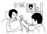
撮影モードとしては、図6に示すように、顔全体の撮影である顔貌撮影、図7に示す上下の歯全体の撮影である全顎撮影、図8に示す歯の1〜2本の撮影を行う歯牙撮影の3種類がある。顔貌撮影及び全顎撮影における動作モードとしては、上述したRGB撮影モードが採用される。また、歯牙撮影にはマルチバンド撮影モードが採用される。上述したマルチバンド撮影待機モードは、歯牙撮影の準備のための装置の位置合わせ時等に採用される。 As the photographing mode, as shown in FIG. 6, facial photographing that is photographing of the entire face, full jaw photographing that is photographing of the entire upper and lower teeth shown in FIG. 7, and photographing of one or two teeth shown in FIG. There are three types of tooth photography to be performed. The RGB shooting mode described above is adopted as an operation mode in facial photography and full jaw photography. In addition, a multiband imaging mode is employed for tooth imaging. The above-described multiband imaging standby mode is employed when the apparatus is aligned for preparation for tooth imaging.
動作モードの変更は、第1乃至第3ファンクションボタンの押下によってなされる。図6乃至図8に示す歯の測定時における動作について説明する。 The operation mode is changed by pressing the first to third function buttons. The operation at the time of tooth measurement shown in FIGS. 6 to 8 will be described.
(RGB撮影)
先ず、図9のステップS1において、初期モードの設定を行う。初期モードは、RGB撮影モードが選択される。撮影者は、カメラユニット69を持ち上げてクレードル72から取り外し、撮影モードを「RGB撮影モード」に合わせる。RGB撮像素子5では順次撮影が行われ、その画像がLCDモニタ86にて表示される。この撮影の時にはLED照明部70a,70bは消灯しており、図6に示すように、外光を利用した撮影が行われる。
(RGB shooting)
First, in step S1 in FIG. 9, the initial mode is set. The RGB mode is selected as the initial mode. The photographer lifts and removes the
以後、ステップS2,S6,S3において、第1乃至第3ファンクションボタンが押下されたか否かの判定が行われる。第1ファンクションボタンの押下によってRGB撮影モードとなり(ステップS5)、第3ファンクションボタンの押下によってマルチバンド撮影待機モード(ステップS4)となる。 Thereafter, in steps S2, S6, and S3, it is determined whether or not the first to third function buttons have been pressed. When the first function button is pressed, the RGB shooting mode is set (step S5), and when the third function button is pressed, the multiband shooting standby mode is set (step S4).
撮影者(歯科医や歯科衛生士)は、LCDモニタ86上の画像を見ながら、被写体(顔、または、全顎)に位置を合わせて、次にフォーカスレバー79を用いてピントを合わせる。この際にカメラ制御CPU81では適正露光になるようにRGB撮像素子5の電子シャッタスピードを制御する。そして、第2ファンクションボタンであるシャッタボタンが押されると、ステップS6から処理をステップS7に移行して、動作モードの判定を行う。この場合には、RGB撮影モードであるので、ステップS9においてRGB撮影が行われる。撮影された画像は、画像メモリ89に記憶される。この際に、RGB画像モード等の付帯情報も一緒に記憶される。
The photographer (dentist or dental hygienist) adjusts the position of the subject (face or whole jaw) while viewing the image on the
(マルチバンド撮影)
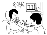
次に、撮影者は、歯牙撮影を行う。この場合には、図10に示すように、カメラユニット69の当付部分の先端に、コンタクトキャップ260を装着する。撮影者は、コンタクトキャップ260を被検者の検査する歯の周辺に当接させる。この場合には、マルチバンド撮影モードへの移行時における電力消費を安定させるために、また、コンタクトキャップ260により外光が遮られるので、撮影者は第3ファンクションボタンを押下して、マルチバンド撮影待機モードに移行させる。カメラ制御CPU81は、ステップS3において、第3ファンクションボタンが押下されたことを検出すると、ステップS4において、マルチバンド撮影待機モードを設定する。
(Multiband shooting)
Next, the photographer performs tooth photography. In this case, as shown in FIG. 10, a
即ち、カメラ制御CPU81は、LEDドライバ83を制御して、7種類のLEDのうちの例えばLEDλ2,λ4,λ7のみを発光させる。これにより、これらのLEDからの照明光による白色光が被検体の歯の周辺に照射され、その反射光が撮像レンズ16及びカラーフィルタアレイ5bを介してRGB撮像素子5の入射面に結像する。こうして、RGB撮像素子5は、3種類のLEDの照明光を利用したRGB撮影を行い、ライブ画像がLCDモニタ86に表示される。マルチバンド撮影待機モードにおいて数種類のLEDに電流を供給しており、マルチバンド撮影時におけるLEDの発光を安定化させることが可能である。
That is, the
撮影者は、LCDモニタ86の表示を見ながら、コンタクトキャップ260の位置決めを行う。撮像範囲が決定すると、撮影者は、シャッタボタンである第2ファンクションボタンを押下する。これにより、カメラ制御CPU81は、ステップS6,S7からステップS8に移行して、マルチバンド撮影を実行する。
The photographer positions the
図11はマルチバンド撮影による単歯画像の撮影処理を示すフローチャートである。 FIG. 11 is a flowchart showing a single-tooth image photographing process by multiband photographing.
マルチバンド撮影時には、カメラ制御CPU81は、図11のステップS11において、7種類のLEDのうちの1種類のLEDをまず発光させる。そして、発光された1つの原色による照明下で、歯を撮像する(ステップS12)。
At the time of multiband shooting, the
その後、全ての原色(上述した例では7つの原色)のLEDを発光させたか否かを判定し(ステップS13)、まだ全ての原色のLEDを発光させていない場合には、未発光の原色を選択する(ステップS14)。その後、上記ステップS11へ戻って、新たに選択した原色のLEDを発光させ、ステップS12において歯を撮像する。 Thereafter, it is determined whether or not the LEDs of all the primary colors (seven primary colors in the above-described example) are caused to emit light (step S13). Select (step S14). Thereafter, the process returns to step S11, the newly selected primary color LED is caused to emit light, and the tooth is imaged in step S12.
こうして、ステップS13において、全ての原色のLEDを発光させたと判定された場合には、次に、LEDの発光を行うことなく歯を撮像する(単歯のバックグラウンド撮像)(ステップS15)。カメラ制御CPU81は、撮像して得た各画像を画像メモリ89に記憶させる。こうして得たマルチバンド撮影画像をPC68に転送して、シェードガイドのシェード番号の算出を行う。
In this way, if it is determined in step S13 that all primary color LEDs have been made to emit light, then the teeth are imaged without emitting the LEDs (single-tooth background imaging) (step S15). The
このように本実施の形態においては、マルチバンド撮影におけるLED発光を安定化させるという理由及びマルチバンド撮影直前には外光が制限されるという理由から、マルチバンド撮影待機モード時には、マルチバンド撮影に用いるLEDを利用した照明を行うようになっている。この場合において、各LEDのうち3原色の色光を発光する3種類のLEDであって、発光効率に優れたLEDを選択して発光させている。これにより、消費電力を著しく低減することが可能である。また、LED及びその近傍の温度上昇も抑制することができ、LED特性を安定化させることができ、キャリブレーションを容易にするという効果も得られる。 As described above, in this embodiment, the multi-band shooting is performed in the multi-band shooting standby mode because the LED light emission in the multi-band shooting is stabilized and the external light is limited immediately before the multi-band shooting. Illumination using the LED to be used is performed. In this case, three types of LEDs that emit light of three primary colors among the LEDs are selected, and LEDs having excellent luminous efficiency are selected to emit light. Thereby, power consumption can be significantly reduced. Moreover, the temperature rise of LED and its vicinity can also be suppressed, LED characteristics can be stabilized, and the effect that calibration is made easy is also acquired.
なお、上記実施の形態においては、マルチバンド撮影待機モードにおいては、RGB原色光に対応する狭帯域のLEDのうち、発光効率が高いLEDを選択的に用いた。しかし、被写体からの反射光はカラーフィルタアレイ5bを介してRGB撮像素子5の入射面に入射することから、LEDの特性だけでなく、カラーフィルタアレイ5bの各色特性も考慮した方がよいことも考えられる。
In the above-described embodiment, in the multiband shooting standby mode, LEDs with high luminous efficiency are selectively used among narrowband LEDs corresponding to RGB primary color light. However, since the reflected light from the subject enters the incident surface of the
例えば、各LED出力とカラーフィルタアレイ5bの出力との積を積分し、最も大きい値が得られるLEDを選択するようにしてもよい。即ち、LEDλ1,λ2については各反射光がカラーフィルタアレイ5bのBフィルタを通過した場合の出力、LEDλ3〜λ5については各反射光がカラーフィルタアレイ5bのGフィルタを通過した場合の出力、LEDλ6,λ7については各反射光がカラーフィルタアレイ5bのRフィルタを通過した場合の出力を夫々求める。各LEDに対応したフィルタ出力が大きく、RGB3原色に対応した3種類のLEDを選択するのである。 For example, the product of each LED output and the output of the color filter array 5b may be integrated to select the LED that provides the largest value. That is, for LEDs λ1 and λ2, the output when each reflected light passes through the B filter of the color filter array 5b, and for LEDs λ3 to λ5, the output when each reflected light passes through the G filter of the color filter array 5b, LED λ6, For λ7, the output when each reflected light passes through the R filter of the color filter array 5b is obtained. The filter output corresponding to each LED is large, and three types of LEDs corresponding to the three primary colors of RGB are selected.
更に、ホワイトバランスを考慮した選択も可能である。即ち、RGB3軸について、各LEDに対応したフィルタ出力を求め、3軸のバランスを考慮することで、良好なホワイトバランスが得られるように、3種類のLEDを選択するのである。この場合には、若干消費電力が増大する可能性はあるが、マルチバンド撮影待機モードにおいても、ホワイトバランスに優れたライブ画像が得られる。 Furthermore, selection considering white balance is also possible. That is, three types of LEDs are selected so that a good white balance can be obtained by obtaining the filter output corresponding to each LED for the RGB three axes and considering the balance of the three axes. In this case, although there is a possibility that the power consumption is slightly increased, a live image excellent in white balance can be obtained even in the multiband shooting standby mode.
更に、カラーフィルタアレイ5bのRGB各色フィルタの中心波長に近い中心波長を有する3種類のLEDを選択してもよい。また、上記各選択条件を組み合わせて、1種類以上のLEDを選択してもよい。いずれの場合でも、全種類のLEDを発光させる場合に比べて、消費電力を低減させることが可能である。 Furthermore, you may select three types of LED which has a center wavelength close | similar to the center wavelength of each RGB color filter of the color filter array 5b. One or more types of LEDs may be selected by combining the above selection conditions. In any case, it is possible to reduce power consumption compared to the case where all types of LEDs emit light.
5…RGB撮像素子、69…カメラユニット、70…照明ユニット、70a,70b…LED照明部、71…制御ユニット、81…カメラ制御CPU、83…LEDドライバ、86…LCDモニタ。
DESCRIPTION OF
代理人 弁理士 伊 藤 進 Agent Patent Attorney Susumu Ito
Claims (5)
カラーフィルタアレイを有し、前記被写体のカラー画像を撮影するためのカラー画像撮像手段と、
4色以上の分光特性の異なる光源を有して、前記被写体を照明する照明手段と、
前記カラー画像撮像手段によるマルチバンド撮影モード時に、前記光源の全ての種類の光源を順次選択して発光させると共に、前記カラー画像撮像手段により動画像を見るためのマルチバンド撮影待機モード時に、前記光源のうちの一部の種類の光源のみを同時に選択して発光させる照明制御手段と
を具備したことを特徴とする撮影装置。 In a photographing device for photographing a subject,
A color image imaging means for capturing a color image of the subject, having a color filter array;
Illuminating means for illuminating the subject having light sources having different spectral characteristics of four or more colors;
In the multiband shooting mode by the color image pickup means, all types of light sources are sequentially selected to emit light, and in the multiband shooting standby mode for viewing moving images by the color image pickup means, the light source And an illumination control means for simultaneously selecting and emitting only some types of light sources.
Priority Applications (1)
| Application Number | Priority Date | Filing Date | Title |
|---|---|---|---|
| JP2004375067A JP4831962B2 (en) | 2004-12-24 | 2004-12-24 | Imaging device |
Applications Claiming Priority (1)
| Application Number | Priority Date | Filing Date | Title |
|---|---|---|---|
| JP2004375067A JP4831962B2 (en) | 2004-12-24 | 2004-12-24 | Imaging device |
Publications (3)
| Publication Number | Publication Date |
|---|---|
| JP2006184033A JP2006184033A (en) | 2006-07-13 |
| JP2006184033A5 JP2006184033A5 (en) | 2008-02-21 |
| JP4831962B2 true JP4831962B2 (en) | 2011-12-07 |
Family
ID=36737270
Family Applications (1)
| Application Number | Title | Priority Date | Filing Date |
|---|---|---|---|
| JP2004375067A Expired - Fee Related JP4831962B2 (en) | 2004-12-24 | 2004-12-24 | Imaging device |
Country Status (1)
| Country | Link |
|---|---|
| JP (1) | JP4831962B2 (en) |
Families Citing this family (3)
| Publication number | Priority date | Publication date | Assignee | Title |
|---|---|---|---|---|
| JP5224178B2 (en) * | 2008-08-12 | 2013-07-03 | 株式会社松風 | Dental colorimeter |
| DE102010040386A1 (en) * | 2010-09-08 | 2012-03-08 | Sirona Dental Systems Gmbh | Dental X-ray device with image acquisition unit for surface detection and method for generating an X-ray image of a patient |
| WO2012066553A1 (en) * | 2010-11-16 | 2012-05-24 | Given Imaging Ltd. | In-vivo imaging device and method for performing spectral analysis |
Family Cites Families (2)
| Publication number | Priority date | Publication date | Assignee | Title |
|---|---|---|---|---|
| JPH11313797A (en) * | 1998-05-06 | 1999-11-16 | Olympus Optical Co Ltd | Endoscope device |
| WO2004012461A1 (en) * | 2002-07-26 | 2004-02-05 | Olympus Optical Co., Ltd. | Image processing system |
-
2004
- 2004-12-24 JP JP2004375067A patent/JP4831962B2/en not_active Expired - Fee Related
Also Published As
| Publication number | Publication date |
|---|---|
| JP2006184033A (en) | 2006-07-13 |
Similar Documents
| Publication | Publication Date | Title |
|---|---|---|
| JP4800591B2 (en) | Shooting system | |
| JP4088313B2 (en) | Image processing system, hospital processing system | |
| JP5968944B2 (en) | Endoscope system, processor device, light source device, operation method of endoscope system, operation method of processor device, operation method of light source device | |
| US7756327B2 (en) | Image processing system having multiple imaging modes | |
| EP2912990B1 (en) | Endoscope system and endoscope system processor device | |
| US8050519B2 (en) | Image combining apparatus | |
| JP2007047045A (en) | Apparatus, method and program for image processing | |
| JP4616318B2 (en) | camera | |
| US11089943B2 (en) | Endoscope system and method of operating the same | |
| JP2010081057A (en) | Image processing apparatus and method, and colorimetry system | |
| JP3989521B2 (en) | Image composition apparatus, method and program | |
| JP4831962B2 (en) | Imaging device | |
| JP7015382B2 (en) | Endoscope system | |
| JP2009195495A (en) | Dental device for measuring color | |
| KR100849007B1 (en) | Imaging system | |
| JP2011069735A (en) | Dental colorimeter | |
| JP4713883B2 (en) | Dental imaging device | |
| WO2019244254A1 (en) | Image processing device, operating method for image processing device, and operation program for image processing device | |
| JP2009053160A (en) | Dental colorimetric device | |
| JP4540469B2 (en) | Dental imaging device |
Legal Events
| Date | Code | Title | Description |
|---|---|---|---|
| A521 | Request for written amendment filed |
Free format text: JAPANESE INTERMEDIATE CODE: A523 Effective date: 20071221 |
|
| A621 | Written request for application examination |
Free format text: JAPANESE INTERMEDIATE CODE: A621 Effective date: 20071221 |
|
| A977 | Report on retrieval |
Free format text: JAPANESE INTERMEDIATE CODE: A971007 Effective date: 20100618 |
|
| A131 | Notification of reasons for refusal |
Free format text: JAPANESE INTERMEDIATE CODE: A131 Effective date: 20100817 |
|
| A521 | Request for written amendment filed |
Free format text: JAPANESE INTERMEDIATE CODE: A523 Effective date: 20101012 |
|
| A521 | Request for written amendment filed |
Free format text: JAPANESE INTERMEDIATE CODE: A523 Effective date: 20101013 |
|
| A131 | Notification of reasons for refusal |
Free format text: JAPANESE INTERMEDIATE CODE: A131 Effective date: 20110301 |
|
| A521 | Request for written amendment filed |
Free format text: JAPANESE INTERMEDIATE CODE: A523 Effective date: 20110419 |
|
| TRDD | Decision of grant or rejection written | ||
| A01 | Written decision to grant a patent or to grant a registration (utility model) |
Free format text: JAPANESE INTERMEDIATE CODE: A01 Effective date: 20110906 |
|
| A01 | Written decision to grant a patent or to grant a registration (utility model) |
Free format text: JAPANESE INTERMEDIATE CODE: A01 |
|
| A61 | First payment of annual fees (during grant procedure) |
Free format text: JAPANESE INTERMEDIATE CODE: A61 Effective date: 20110920 |
|
| R151 | Written notification of patent or utility model registration |
Ref document number: 4831962 Country of ref document: JP Free format text: JAPANESE INTERMEDIATE CODE: R151 |
|
| FPAY | Renewal fee payment (event date is renewal date of database) |
Free format text: PAYMENT UNTIL: 20140930 Year of fee payment: 3 |
|
| S531 | Written request for registration of change of domicile |
Free format text: JAPANESE INTERMEDIATE CODE: R313531 |
|
| R350 | Written notification of registration of transfer |
Free format text: JAPANESE INTERMEDIATE CODE: R350 |
|
| R250 | Receipt of annual fees |
Free format text: JAPANESE INTERMEDIATE CODE: R250 |
|
| R250 | Receipt of annual fees |
Free format text: JAPANESE INTERMEDIATE CODE: R250 |
|
| LAPS | Cancellation because of no payment of annual fees |