JP4830912B2 - Control device for internal combustion engine - Google Patents
Control device for internal combustion engine Download PDFInfo
- Publication number
- JP4830912B2 JP4830912B2 JP2007054183A JP2007054183A JP4830912B2 JP 4830912 B2 JP4830912 B2 JP 4830912B2 JP 2007054183 A JP2007054183 A JP 2007054183A JP 2007054183 A JP2007054183 A JP 2007054183A JP 4830912 B2 JP4830912 B2 JP 4830912B2
- Authority
- JP
- Japan
- Prior art keywords
- value
- nox
- combustion engine
- internal combustion
- nox concentration
- Prior art date
- Legal status (The legal status is an assumption and is not a legal conclusion. Google has not performed a legal analysis and makes no representation as to the accuracy of the status listed.)
- Expired - Fee Related
Links
Images


Classifications
-
- F—MECHANICAL ENGINEERING; LIGHTING; HEATING; WEAPONS; BLASTING
- F01—MACHINES OR ENGINES IN GENERAL; ENGINE PLANTS IN GENERAL; STEAM ENGINES
- F01N—GAS-FLOW SILENCERS OR EXHAUST APPARATUS FOR MACHINES OR ENGINES IN GENERAL; GAS-FLOW SILENCERS OR EXHAUST APPARATUS FOR INTERNAL COMBUSTION ENGINES
- F01N3/00—Exhaust or silencing apparatus having means for purifying, rendering innocuous, or otherwise treating exhaust
- F01N3/08—Exhaust or silencing apparatus having means for purifying, rendering innocuous, or otherwise treating exhaust for rendering innocuous
- F01N3/0807—Exhaust or silencing apparatus having means for purifying, rendering innocuous, or otherwise treating exhaust for rendering innocuous by using absorbents or adsorbents
- F01N3/0828—Exhaust or silencing apparatus having means for purifying, rendering innocuous, or otherwise treating exhaust for rendering innocuous by using absorbents or adsorbents characterised by the absorbed or adsorbed substances
- F01N3/0842—Nitrogen oxides
-
- F—MECHANICAL ENGINEERING; LIGHTING; HEATING; WEAPONS; BLASTING
- F01—MACHINES OR ENGINES IN GENERAL; ENGINE PLANTS IN GENERAL; STEAM ENGINES
- F01N—GAS-FLOW SILENCERS OR EXHAUST APPARATUS FOR MACHINES OR ENGINES IN GENERAL; GAS-FLOW SILENCERS OR EXHAUST APPARATUS FOR INTERNAL COMBUSTION ENGINES
- F01N3/00—Exhaust or silencing apparatus having means for purifying, rendering innocuous, or otherwise treating exhaust
- F01N3/08—Exhaust or silencing apparatus having means for purifying, rendering innocuous, or otherwise treating exhaust for rendering innocuous
- F01N3/0807—Exhaust or silencing apparatus having means for purifying, rendering innocuous, or otherwise treating exhaust for rendering innocuous by using absorbents or adsorbents
- F01N3/0814—Exhaust or silencing apparatus having means for purifying, rendering innocuous, or otherwise treating exhaust for rendering innocuous by using absorbents or adsorbents combined with catalytic converters, e.g. NOx absorption/storage reduction catalysts
-
- F—MECHANICAL ENGINEERING; LIGHTING; HEATING; WEAPONS; BLASTING
- F01—MACHINES OR ENGINES IN GENERAL; ENGINE PLANTS IN GENERAL; STEAM ENGINES
- F01N—GAS-FLOW SILENCERS OR EXHAUST APPARATUS FOR MACHINES OR ENGINES IN GENERAL; GAS-FLOW SILENCERS OR EXHAUST APPARATUS FOR INTERNAL COMBUSTION ENGINES
- F01N9/00—Electrical control of exhaust gas treating apparatus
-
- F—MECHANICAL ENGINEERING; LIGHTING; HEATING; WEAPONS; BLASTING
- F02—COMBUSTION ENGINES; HOT-GAS OR COMBUSTION-PRODUCT ENGINE PLANTS
- F02D—CONTROLLING COMBUSTION ENGINES
- F02D13/00—Controlling the engine output power by varying inlet or exhaust valve operating characteristics, e.g. timing
- F02D13/02—Controlling the engine output power by varying inlet or exhaust valve operating characteristics, e.g. timing during engine operation
- F02D13/0203—Variable control of intake and exhaust valves
-
- F—MECHANICAL ENGINEERING; LIGHTING; HEATING; WEAPONS; BLASTING
- F02—COMBUSTION ENGINES; HOT-GAS OR COMBUSTION-PRODUCT ENGINE PLANTS
- F02D—CONTROLLING COMBUSTION ENGINES
- F02D35/00—Controlling engines, dependent on conditions exterior or interior to engines, not otherwise provided for
- F02D35/02—Controlling engines, dependent on conditions exterior or interior to engines, not otherwise provided for on interior conditions
- F02D35/023—Controlling engines, dependent on conditions exterior or interior to engines, not otherwise provided for on interior conditions by determining the cylinder pressure
-
- F—MECHANICAL ENGINEERING; LIGHTING; HEATING; WEAPONS; BLASTING
- F02—COMBUSTION ENGINES; HOT-GAS OR COMBUSTION-PRODUCT ENGINE PLANTS
- F02D—CONTROLLING COMBUSTION ENGINES
- F02D41/00—Electrical control of supply of combustible mixture or its constituents
- F02D41/02—Circuit arrangements for generating control signals
- F02D41/14—Introducing closed-loop corrections
- F02D41/1438—Introducing closed-loop corrections using means for determining characteristics of the combustion gases; Sensors therefor
- F02D41/1444—Introducing closed-loop corrections using means for determining characteristics of the combustion gases; Sensors therefor characterised by the characteristics of the combustion gases
- F02D41/146—Introducing closed-loop corrections using means for determining characteristics of the combustion gases; Sensors therefor characterised by the characteristics of the combustion gases the characteristics being an NOx content or concentration
- F02D41/1461—Introducing closed-loop corrections using means for determining characteristics of the combustion gases; Sensors therefor characterised by the characteristics of the combustion gases the characteristics being an NOx content or concentration of the exhaust gases emitted by the engine
- F02D41/1462—Introducing closed-loop corrections using means for determining characteristics of the combustion gases; Sensors therefor characterised by the characteristics of the combustion gases the characteristics being an NOx content or concentration of the exhaust gases emitted by the engine with determination means using an estimation
-
- F—MECHANICAL ENGINEERING; LIGHTING; HEATING; WEAPONS; BLASTING
- F02—COMBUSTION ENGINES; HOT-GAS OR COMBUSTION-PRODUCT ENGINE PLANTS
- F02D—CONTROLLING COMBUSTION ENGINES
- F02D41/00—Electrical control of supply of combustible mixture or its constituents
- F02D41/22—Safety or indicating devices for abnormal conditions
- F02D41/222—Safety or indicating devices for abnormal conditions relating to the failure of sensors or parameter detection devices
-
- F—MECHANICAL ENGINEERING; LIGHTING; HEATING; WEAPONS; BLASTING
- F01—MACHINES OR ENGINES IN GENERAL; ENGINE PLANTS IN GENERAL; STEAM ENGINES
- F01L—CYCLICALLY OPERATING VALVES FOR MACHINES OR ENGINES
- F01L1/00—Valve-gear or valve arrangements, e.g. lift-valve gear
- F01L1/34—Valve-gear or valve arrangements, e.g. lift-valve gear characterised by the provision of means for changing the timing of the valves without changing the duration of opening and without affecting the magnitude of the valve lift
- F01L1/344—Valve-gear or valve arrangements, e.g. lift-valve gear characterised by the provision of means for changing the timing of the valves without changing the duration of opening and without affecting the magnitude of the valve lift changing the angular relationship between crankshaft and camshaft, e.g. using helicoidal gear
-
- F—MECHANICAL ENGINEERING; LIGHTING; HEATING; WEAPONS; BLASTING
- F01—MACHINES OR ENGINES IN GENERAL; ENGINE PLANTS IN GENERAL; STEAM ENGINES
- F01L—CYCLICALLY OPERATING VALVES FOR MACHINES OR ENGINES
- F01L1/00—Valve-gear or valve arrangements, e.g. lift-valve gear
- F01L1/02—Valve drive
- F01L1/04—Valve drive by means of cams, camshafts, cam discs, eccentrics or the like
- F01L1/047—Camshafts
- F01L1/053—Camshafts overhead type
- F01L2001/0537—Double overhead camshafts [DOHC]
-
- F—MECHANICAL ENGINEERING; LIGHTING; HEATING; WEAPONS; BLASTING
- F01—MACHINES OR ENGINES IN GENERAL; ENGINE PLANTS IN GENERAL; STEAM ENGINES
- F01L—CYCLICALLY OPERATING VALVES FOR MACHINES OR ENGINES
- F01L1/00—Valve-gear or valve arrangements, e.g. lift-valve gear
- F01L1/34—Valve-gear or valve arrangements, e.g. lift-valve gear characterised by the provision of means for changing the timing of the valves without changing the duration of opening and without affecting the magnitude of the valve lift
- F01L1/344—Valve-gear or valve arrangements, e.g. lift-valve gear characterised by the provision of means for changing the timing of the valves without changing the duration of opening and without affecting the magnitude of the valve lift changing the angular relationship between crankshaft and camshaft, e.g. using helicoidal gear
- F01L2001/34486—Location and number of the means for changing the angular relationship
- F01L2001/34496—Two phasers on different camshafts
-
- F—MECHANICAL ENGINEERING; LIGHTING; HEATING; WEAPONS; BLASTING
- F01—MACHINES OR ENGINES IN GENERAL; ENGINE PLANTS IN GENERAL; STEAM ENGINES
- F01L—CYCLICALLY OPERATING VALVES FOR MACHINES OR ENGINES
- F01L2800/00—Methods of operation using a variable valve timing mechanism
- F01L2800/10—Providing exhaust gas recirculation [EGR]
-
- F—MECHANICAL ENGINEERING; LIGHTING; HEATING; WEAPONS; BLASTING
- F01—MACHINES OR ENGINES IN GENERAL; ENGINE PLANTS IN GENERAL; STEAM ENGINES
- F01N—GAS-FLOW SILENCERS OR EXHAUST APPARATUS FOR MACHINES OR ENGINES IN GENERAL; GAS-FLOW SILENCERS OR EXHAUST APPARATUS FOR INTERNAL COMBUSTION ENGINES
- F01N2560/00—Exhaust systems with means for detecting or measuring exhaust gas components or characteristics
- F01N2560/02—Exhaust systems with means for detecting or measuring exhaust gas components or characteristics the means being an exhaust gas sensor
- F01N2560/026—Exhaust systems with means for detecting or measuring exhaust gas components or characteristics the means being an exhaust gas sensor for measuring or detecting NOx
-
- F—MECHANICAL ENGINEERING; LIGHTING; HEATING; WEAPONS; BLASTING
- F01—MACHINES OR ENGINES IN GENERAL; ENGINE PLANTS IN GENERAL; STEAM ENGINES
- F01N—GAS-FLOW SILENCERS OR EXHAUST APPARATUS FOR MACHINES OR ENGINES IN GENERAL; GAS-FLOW SILENCERS OR EXHAUST APPARATUS FOR INTERNAL COMBUSTION ENGINES
- F01N2560/00—Exhaust systems with means for detecting or measuring exhaust gas components or characteristics
- F01N2560/08—Exhaust systems with means for detecting or measuring exhaust gas components or characteristics the means being a pressure sensor
-
- F—MECHANICAL ENGINEERING; LIGHTING; HEATING; WEAPONS; BLASTING
- F01—MACHINES OR ENGINES IN GENERAL; ENGINE PLANTS IN GENERAL; STEAM ENGINES
- F01N—GAS-FLOW SILENCERS OR EXHAUST APPARATUS FOR MACHINES OR ENGINES IN GENERAL; GAS-FLOW SILENCERS OR EXHAUST APPARATUS FOR INTERNAL COMBUSTION ENGINES
- F01N2570/00—Exhaust treating apparatus eliminating, absorbing or adsorbing specific elements or compounds
- F01N2570/14—Nitrogen oxides
-
- F—MECHANICAL ENGINEERING; LIGHTING; HEATING; WEAPONS; BLASTING
- F01—MACHINES OR ENGINES IN GENERAL; ENGINE PLANTS IN GENERAL; STEAM ENGINES
- F01N—GAS-FLOW SILENCERS OR EXHAUST APPARATUS FOR MACHINES OR ENGINES IN GENERAL; GAS-FLOW SILENCERS OR EXHAUST APPARATUS FOR INTERNAL COMBUSTION ENGINES
- F01N2900/00—Details of electrical control or of the monitoring of the exhaust gas treating apparatus
- F01N2900/06—Parameters used for exhaust control or diagnosing
- F01N2900/14—Parameters used for exhaust control or diagnosing said parameters being related to the exhaust gas
-
- F—MECHANICAL ENGINEERING; LIGHTING; HEATING; WEAPONS; BLASTING
- F02—COMBUSTION ENGINES; HOT-GAS OR COMBUSTION-PRODUCT ENGINE PLANTS
- F02D—CONTROLLING COMBUSTION ENGINES
- F02D41/00—Electrical control of supply of combustible mixture or its constituents
- F02D41/0002—Controlling intake air
- F02D2041/001—Controlling intake air for engines with variable valve actuation
-
- F—MECHANICAL ENGINEERING; LIGHTING; HEATING; WEAPONS; BLASTING
- F02—COMBUSTION ENGINES; HOT-GAS OR COMBUSTION-PRODUCT ENGINE PLANTS
- F02D—CONTROLLING COMBUSTION ENGINES
- F02D35/00—Controlling engines, dependent on conditions exterior or interior to engines, not otherwise provided for
- F02D35/02—Controlling engines, dependent on conditions exterior or interior to engines, not otherwise provided for on interior conditions
- F02D35/028—Controlling engines, dependent on conditions exterior or interior to engines, not otherwise provided for on interior conditions by determining the combustion timing or phasing
-
- F—MECHANICAL ENGINEERING; LIGHTING; HEATING; WEAPONS; BLASTING
- F02—COMBUSTION ENGINES; HOT-GAS OR COMBUSTION-PRODUCT ENGINE PLANTS
- F02D—CONTROLLING COMBUSTION ENGINES
- F02D41/00—Electrical control of supply of combustible mixture or its constituents
- F02D41/02—Circuit arrangements for generating control signals
- F02D41/14—Introducing closed-loop corrections
- F02D41/1438—Introducing closed-loop corrections using means for determining characteristics of the combustion gases; Sensors therefor
- F02D41/1444—Introducing closed-loop corrections using means for determining characteristics of the combustion gases; Sensors therefor characterised by the characteristics of the combustion gases
- F02D41/1454—Introducing closed-loop corrections using means for determining characteristics of the combustion gases; Sensors therefor characterised by the characteristics of the combustion gases the characteristics being an oxygen content or concentration or the air-fuel ratio
-
- F—MECHANICAL ENGINEERING; LIGHTING; HEATING; WEAPONS; BLASTING
- F02—COMBUSTION ENGINES; HOT-GAS OR COMBUSTION-PRODUCT ENGINE PLANTS
- F02D—CONTROLLING COMBUSTION ENGINES
- F02D41/00—Electrical control of supply of combustible mixture or its constituents
- F02D41/02—Circuit arrangements for generating control signals
- F02D41/14—Introducing closed-loop corrections
- F02D41/1438—Introducing closed-loop corrections using means for determining characteristics of the combustion gases; Sensors therefor
- F02D41/1444—Introducing closed-loop corrections using means for determining characteristics of the combustion gases; Sensors therefor characterised by the characteristics of the combustion gases
- F02D41/146—Introducing closed-loop corrections using means for determining characteristics of the combustion gases; Sensors therefor characterised by the characteristics of the combustion gases the characteristics being an NOx content or concentration
- F02D41/1461—Introducing closed-loop corrections using means for determining characteristics of the combustion gases; Sensors therefor characterised by the characteristics of the combustion gases the characteristics being an NOx content or concentration of the exhaust gases emitted by the engine
-
- F—MECHANICAL ENGINEERING; LIGHTING; HEATING; WEAPONS; BLASTING
- F02—COMBUSTION ENGINES; HOT-GAS OR COMBUSTION-PRODUCT ENGINE PLANTS
- F02D—CONTROLLING COMBUSTION ENGINES
- F02D41/00—Electrical control of supply of combustible mixture or its constituents
- F02D41/02—Circuit arrangements for generating control signals
- F02D41/18—Circuit arrangements for generating control signals by measuring intake air flow
-
- F—MECHANICAL ENGINEERING; LIGHTING; HEATING; WEAPONS; BLASTING
- F02—COMBUSTION ENGINES; HOT-GAS OR COMBUSTION-PRODUCT ENGINE PLANTS
- F02M—SUPPLYING COMBUSTION ENGINES IN GENERAL WITH COMBUSTIBLE MIXTURES OR CONSTITUENTS THEREOF
- F02M69/00—Low-pressure fuel-injection apparatus ; Apparatus with both continuous and intermittent injection; Apparatus injecting different types of fuel
- F02M69/04—Injectors peculiar thereto
- F02M69/042—Positioning of injectors with respect to engine, e.g. in the air intake conduit
- F02M69/046—Positioning of injectors with respect to engine, e.g. in the air intake conduit for injecting into both the combustion chamber and the intake conduit
-
- Y—GENERAL TAGGING OF NEW TECHNOLOGICAL DEVELOPMENTS; GENERAL TAGGING OF CROSS-SECTIONAL TECHNOLOGIES SPANNING OVER SEVERAL SECTIONS OF THE IPC; TECHNICAL SUBJECTS COVERED BY FORMER USPC CROSS-REFERENCE ART COLLECTIONS [XRACs] AND DIGESTS
- Y02—TECHNOLOGIES OR APPLICATIONS FOR MITIGATION OR ADAPTATION AGAINST CLIMATE CHANGE
- Y02A—TECHNOLOGIES FOR ADAPTATION TO CLIMATE CHANGE
- Y02A50/00—TECHNOLOGIES FOR ADAPTATION TO CLIMATE CHANGE in human health protection, e.g. against extreme weather
- Y02A50/20—Air quality improvement or preservation, e.g. vehicle emission control or emission reduction by using catalytic converters
-
- Y—GENERAL TAGGING OF NEW TECHNOLOGICAL DEVELOPMENTS; GENERAL TAGGING OF CROSS-SECTIONAL TECHNOLOGIES SPANNING OVER SEVERAL SECTIONS OF THE IPC; TECHNICAL SUBJECTS COVERED BY FORMER USPC CROSS-REFERENCE ART COLLECTIONS [XRACs] AND DIGESTS
- Y02—TECHNOLOGIES OR APPLICATIONS FOR MITIGATION OR ADAPTATION AGAINST CLIMATE CHANGE
- Y02T—CLIMATE CHANGE MITIGATION TECHNOLOGIES RELATED TO TRANSPORTATION
- Y02T10/00—Road transport of goods or passengers
- Y02T10/10—Internal combustion engine [ICE] based vehicles
- Y02T10/12—Improving ICE efficiencies
-
- Y—GENERAL TAGGING OF NEW TECHNOLOGICAL DEVELOPMENTS; GENERAL TAGGING OF CROSS-SECTIONAL TECHNOLOGIES SPANNING OVER SEVERAL SECTIONS OF THE IPC; TECHNICAL SUBJECTS COVERED BY FORMER USPC CROSS-REFERENCE ART COLLECTIONS [XRACs] AND DIGESTS
- Y02—TECHNOLOGIES OR APPLICATIONS FOR MITIGATION OR ADAPTATION AGAINST CLIMATE CHANGE
- Y02T—CLIMATE CHANGE MITIGATION TECHNOLOGIES RELATED TO TRANSPORTATION
- Y02T10/00—Road transport of goods or passengers
- Y02T10/10—Internal combustion engine [ICE] based vehicles
- Y02T10/40—Engine management systems
Landscapes
- Engineering & Computer Science (AREA)
- Chemical & Material Sciences (AREA)
- Combustion & Propulsion (AREA)
- Mechanical Engineering (AREA)
- General Engineering & Computer Science (AREA)
- Chemical Kinetics & Catalysis (AREA)
- Combined Controls Of Internal Combustion Engines (AREA)
- Output Control And Ontrol Of Special Type Engine (AREA)
- Electrical Control Of Ignition Timing (AREA)
- Exhaust Gas After Treatment (AREA)
Description
この発明は、内燃機関の制御装置に係り、特に、車両に搭載される内燃機関の排気ガスに含まれるNOxの濃度を正確に推定するうえで好適な内燃機関の制御装置に関する。 The present invention relates to an internal combustion engine control apparatus, and more particularly to an internal combustion engine control apparatus suitable for accurately estimating the concentration of NOx contained in exhaust gas of an internal combustion engine mounted on a vehicle.
従来、例えば特開2002−195071号公報に開示されるように、内燃機関の排気ガスに含まれるNOxの濃度を推定する機能を有するシステムが知られている。より具体的には、上記の特許文献には、吸入空気量、吸気温度、吸気圧力、空燃比、及びEGR(Exhaust Gas Recirculation)率に基づいて、排気ガスのNOx濃度を推定する手法が開示されている。 Conventionally, as disclosed in, for example, Japanese Patent Laid-Open No. 2002-195071, a system having a function of estimating the concentration of NOx contained in exhaust gas of an internal combustion engine is known. More specifically, the above patent document discloses a method for estimating the NOx concentration of exhaust gas based on the intake air amount, intake air temperature, intake air pressure, air-fuel ratio, and EGR (Exhaust Gas Recirculation) rate. ing.
排気ガスのNOx濃度が演算により推定できれば、例えば、NOx濃度が許容値を超えないように内燃機関を制御することが可能となる。このため、上記の手法でNOx濃度を推定することは、内燃機関のエミッション特性を改善するうえで有用である。 If the NOx concentration of the exhaust gas can be estimated by calculation, for example, the internal combustion engine can be controlled so that the NOx concentration does not exceed an allowable value. For this reason, estimating the NOx concentration by the above method is useful for improving the emission characteristics of the internal combustion engine.
しかしながら、排気ガスのNOx濃度は、筒内における混合気の燃焼状態に応じて大きな変動を示す。また、筒内における混合気の燃焼状態は、点火時期が変わることにより、更には、ノックが発生することにより、大きく変化する。そして、上記従来のシステムでは、このような燃焼状態の変化をNOx濃度の推定に反映させることはできない。この点、上記従来のシステムは、NOx濃度の推定精度において改良の余地を残すものであった。 However, the NOx concentration of the exhaust gas varies greatly depending on the combustion state of the air-fuel mixture in the cylinder. Further, the combustion state of the air-fuel mixture in the cylinder changes greatly when the ignition timing changes and further when knocking occurs. In the conventional system, such a change in the combustion state cannot be reflected in the estimation of the NOx concentration. In this regard, the conventional system described above leaves room for improvement in the NOx concentration estimation accuracy.
この発明は、上述のような課題を解決するためになされたもので、筒内圧を基礎データとして用いることにより排気ガスのNOx濃度を精度良く推定することのできる内燃機関の制御装置を提供することを目的とする。 The present invention has been made to solve the above-described problems, and provides an internal combustion engine control apparatus capable of accurately estimating the NOx concentration of exhaust gas by using the in-cylinder pressure as basic data. With the goal.
第1の発明は、上記の目的を達成するため、内燃機関の制御装置であって、
内燃機関の筒内圧を検出する筒内圧センサと、
前記筒内圧に基づいて、前記筒内で消費される内部エネルギと相関を有する内部エネルギ相関値を算出する内部エネルギ相関値算出手段と、
前記内部エネルギ相関値に基づいて、排気ガス中のNOx濃度推定値を算出するNOx濃度推定手段と、を備え、
前記内部エネルギ相関値算出手段は、
膨張行程の開始後における特定クランク角までに終了した燃焼の割合を表すMFBを、前記筒内圧に基づいて算出するMFB算出手段を備え、
当該MFBを前記内部エネルギ相関値として算出することを特徴とする。
In order to achieve the above object, a first invention is a control device for an internal combustion engine,
An in-cylinder pressure sensor for detecting an in-cylinder pressure of the internal combustion engine;
An internal energy correlation value calculating means for calculating an internal energy correlation value having a correlation with the internal energy consumed in the cylinder based on the in-cylinder pressure;
NOx concentration estimation means for calculating an NOx concentration estimated value in the exhaust gas based on the internal energy correlation value ,
The internal energy correlation value calculating means includes:
MFB calculating means for calculating the MFB that represents the ratio of combustion that has been completed by the specific crank angle after the start of the expansion stroke, based on the in-cylinder pressure,
It characterized that you calculate the MFB as said internal energy correlation value.
また、第2の発明は、第1の発明において、
内燃機関の吸入空気量を検出する吸入空気量検出手段を備え、
前記NOx濃度推定手段は、
前記内部エネルギ相関値に基づいて、内燃機関から排出されるNOx排出量を算出するNOx量算出手段と、
前記NOx排出量を前記吸入空気量で規格化することにより前記NOx濃度推定値を算出する規格化手段と、を含むことを特徴とする。
The second invention is the first invention, wherein
Intake air amount detection means for detecting the intake air amount of the internal combustion engine,
The NOx concentration estimating means includes
NOx amount calculating means for calculating the NOx emission amount discharged from the internal combustion engine based on the internal energy correlation value;
Normalizing means for calculating the NOx concentration estimated value by normalizing the NOx emission amount with the intake air amount.
また、第3の発明は、第1又は第2の発明において、
内燃機関の吸入空気量を検出する吸入空気量検出手段を備え、
前記NOx濃度推定手段は、前記吸入空気量が多量であるほど、前記NOx濃度推定値を低く補正する補正手段を含むことを特徴とする。
The third invention is the first or second invention, wherein
Intake air amount detection means for detecting the intake air amount of the internal combustion engine,
The NOx concentration estimating means includes correction means for correcting the NOx concentration estimated value to be lower as the intake air amount is larger.
また、第4の発明は、第1乃至第3の発明の何れかにおいて、
筒内で燃焼する混合気の空燃比を検出する空燃比検出手段を備え、
前記NOx濃度推定手段は、前記空燃比がリーンであるほど前記NOx濃度推定値を高く補正する補正手段を含むことを特徴とする。
According to a fourth invention, in any one of the first to third inventions,
Air-fuel ratio detection means for detecting the air-fuel ratio of the air-fuel mixture combusted in the cylinder,
The NOx concentration estimating means includes a correcting means for correcting the NOx concentration estimated value higher as the air-fuel ratio becomes leaner.
また、第5の発明は、第1乃至第4の発明の何れかにおいて、
排気行程の後に筒内に残留する残留ガス量と相関を有する残留ガス量相関値を検知する残留ガス量相関値検知手段を備え、
前記NOx濃度推定手段は、前記残留ガス量相関値に基づいて前記残留ガス量が多いと推定されるほど、前記NOx濃度推定値を低く補正する補正手段を含むことを特徴とする。
According to a fifth invention, in any one of the first to fourth inventions,
A residual gas amount correlation value detecting means for detecting a residual gas amount correlation value correlated with a residual gas amount remaining in the cylinder after the exhaust stroke;
The NOx concentration estimating means includes correction means for correcting the NOx concentration estimated value to be lower as the residual gas amount is estimated to be larger based on the residual gas amount correlation value.
また、第6の発明は、第5の発明において、
内燃機関の吸入空気量を検出する吸入空気量検出手段を備え、
前記補正手段は、前記吸入空気量と前記残留ガス量との和が多いと推定されるほど、前記NOx濃度推定値を低く補正することを特徴とする。
The sixth invention is the fifth invention, wherein
Intake air amount detection means for detecting the intake air amount of the internal combustion engine,
The correction means corrects the NOx concentration estimated value to be lower as the sum of the intake air amount and the residual gas amount is estimated to be larger.
また、第7の発明は、第1乃至第6の発明の何れかにおいて、
前記NOx濃度推定値が、NOx濃度目標値に近づくように内燃機関を制御する制御手段と、
内燃機関の運転状態に基づいて、前記NOx濃度目標値を設定するNOx濃度目標値設定手段と、
を備えることを特徴とする。
According to a seventh invention, in any one of the first to sixth inventions,
Control means for controlling the internal combustion engine so that the NOx concentration estimated value approaches the NOx concentration target value;
NOx concentration target value setting means for setting the NOx concentration target value based on the operating state of the internal combustion engine;
It is characterized by providing.
また、第8の発明は、第1乃至第7の発明の何れかにおいて、
内燃機関の出力効率と相関を有する出力効率指標を算出する出力効率指標算出手段と、
前記出力効率指標と、出力効率指標目標値との差を指標偏差として算出する指標偏差算出手段と、
前記NOx濃度推定値と、NOx濃度目標値との差を濃度偏差として算出する濃度偏差算出手段と、
前記指標偏差が大きいほど大きな値となり、かつ、前記濃度偏差が大きいほど大きな値となる評価値を算出する評価値算出手段と、
前記評価値が最小になるように、内燃機関の点火時期を制御する点火時期制御手段と、
を備えることを特徴とする。
Further, an eighth invention is any one of the first to seventh inventions,
An output efficiency index calculating means for calculating an output efficiency index having a correlation with the output efficiency of the internal combustion engine;
An index deviation calculating means for calculating a difference between the output efficiency index and an output efficiency index target value as an index deviation;
A concentration deviation calculating means for calculating a difference between the NOx concentration estimated value and the NOx concentration target value as a concentration deviation;
An evaluation value calculating means for calculating an evaluation value that becomes a larger value as the index deviation is larger and becomes a larger value as the concentration deviation is larger;
Ignition timing control means for controlling the ignition timing of the internal combustion engine so that the evaluation value is minimized;
It is characterized by providing.
また、第9の発明は、第8の発明において、
前記評価値算出手段は、前記指標偏差と前記濃度偏差とを、それぞれの重み係数の割合で前記評価値に反映させ、
内燃機関の状態に応じて、前記重み係数の割合を変化させる重み係数変更手段を備えることを特徴とする。
The ninth invention is the eighth invention, wherein
The evaluation value calculation means reflects the index deviation and the concentration deviation in the evaluation value at a ratio of respective weighting factors,
Weight coefficient changing means for changing the ratio of the weight coefficient according to the state of the internal combustion engine is provided.
また、第10の発明は、第9の発明において、
排気ガスを浄化するための触媒と、
前記触媒の劣化を判定する触媒劣化判定手段と、を備え、
前記重み係数変更手段は、前記触媒の劣化が認められた場合に、前記濃度偏差の重み係数の割合を大きくする劣化対応手段を含むことを特徴とする。
The tenth invention is the ninth invention, wherein
A catalyst for purifying exhaust gas,
Catalyst deterioration determination means for determining deterioration of the catalyst,
The weighting factor changing means includes deterioration countermeasure means for increasing the ratio of the weighting factor of the concentration deviation when deterioration of the catalyst is recognized.
また、第11の発明は、第9又は第10の発明において、
排気ガスを浄化するための触媒と、
前記触媒のNOx浄化余力を推定する浄化余力推定手段と、
前記触媒のNOx浄化余力を回復させるための再生処理を実行する再生手段と、
前記再生処理の実行可否を判断する実行可否判断手段と、を備え、
前記重み係数変更手段は、前記NOx浄化余力が判定値以下であり、かつ、前記再生処理の実行が不可である場合に、前記濃度偏差の重み係数の割合を大きくする再生不可対応手段を含むことを特徴とする。
The eleventh invention is the ninth or tenth invention,
A catalyst for purifying exhaust gas,
A purification capacity estimating means for estimating a NOx purification capacity of the catalyst;
Regeneration means for performing regeneration processing for recovering the NOx purification capacity of the catalyst;
Execution feasibility judgment means for judging whether or not the reproduction process can be performed,
The weighting factor changing unit includes a nonregeneration handling unit that increases a weighting factor ratio of the concentration deviation when the NOx purification remaining capacity is equal to or less than a determination value and the regeneration process cannot be performed. It is characterized by.
また、第12の発明は、第1乃至第7の発明の何れかにおいて、
内燃機関の出力効率と相関を有する出力効率指標を算出する出力効率指標算出手段と、
前記NOx濃度推定値と、NOx濃度目標値との差を濃度偏差として算出する濃度偏差算出手段と、
前記出力効率指標の基本目標値を前記濃度偏差に基づいて修正することにより出力効率指標目標値を設定する指標目標値設定手段と、
前記出力効率指標が、前記出力効率指標目標値に近づくように、内燃機関の点火時期を制御する点火時期制御手段と、
を備えることを特徴とする。
In addition, a twelfth aspect of the invention is any one of the first to seventh aspects of the invention,
An output efficiency index calculating means for calculating an output efficiency index having a correlation with the output efficiency of the internal combustion engine;
A concentration deviation calculating means for calculating a difference between the NOx concentration estimated value and the NOx concentration target value as a concentration deviation;
Index target value setting means for setting the output efficiency index target value by correcting the basic target value of the output efficiency index based on the concentration deviation;
Ignition timing control means for controlling the ignition timing of the internal combustion engine so that the output efficiency index approaches the output efficiency index target value;
It is characterized by providing.
また、第13の発明は、第1乃至第12の発明の何れかにおいて、
バルブオーバーラップ期間が変化するように、内燃機関の吸気弁及び排気弁の少なくとも一方の開弁特性を変更することのできる可変動弁機構と、
前記NOx濃度推定値が、NOx濃度目標値に近づくように、前記可変動弁機構を制御する制御手段と、
を備えることを特徴とする。
The thirteenth aspect of the invention is any one of the first to twelfth aspects of the invention.
A variable valve mechanism capable of changing a valve opening characteristic of at least one of an intake valve and an exhaust valve of an internal combustion engine so that a valve overlap period changes;
Control means for controlling the variable valve mechanism so that the NOx concentration estimated value approaches the NOx concentration target value;
It is characterized by providing.
また、第14の発明は、内燃機関の制御装置であって、
内燃機関の筒内圧を検出する筒内圧センサと、
前記筒内圧に基づいて、前記筒内で消費される内部エネルギと相関を有する内部エネルギ相関値を算出する内部エネルギ相関値算出手段と、
前記内部エネルギ相関値に基づいて、排気ガス中のNOx濃度推定値を算出するNOx濃度推定手段と、
機関回転数を検知する回転数センサと、を備え、
前記内部エネルギ相関値算出手段は、
筒内容積と、クランク角当たりの筒内圧力変化率との積を、膨張行程において積分した結果に基づいて前記内部エネルギ相関値を算出する第1の算出手段と、
膨張行程の開始直後の筒内容積と筒内圧力の積と、前記膨張行程の終了時点付近における筒内容積と筒内圧力の積との差に基づいて、前記内部エネルギ相関値を算出する第2の算出手段と、
機関回転数が判定値以下である場合には前記第1の算出手段による算出を選択し、機関回転数が前記判定値を超える場合には前記第2の算出手段による算出を選択する算出手法選択手段と、
を備えることを特徴とする。
A fourteenth aspect of the invention is a control device for an internal combustion engine,
An in-cylinder pressure sensor for detecting an in-cylinder pressure of the internal combustion engine;
An internal energy correlation value calculating means for calculating an internal energy correlation value having a correlation with the internal energy consumed in the cylinder based on the in-cylinder pressure;
NOx concentration estimating means for calculating an estimated NOx concentration value in the exhaust gas based on the internal energy correlation value;
Comprising a speed sensor for detecting the engine speed, and
The internal energy correlation value calculating means includes:
First calculation means for calculating the internal energy correlation value based on a result obtained by integrating a product of an in-cylinder volume and an in-cylinder pressure change rate per crank angle in an expansion stroke;
The internal energy correlation value is calculated based on the difference between the product of the cylinder volume immediately after the start of the expansion stroke and the cylinder pressure and the product of the cylinder volume and the cylinder pressure near the end of the expansion stroke. Two calculating means;
Calculation method selection for selecting calculation by the first calculation means when the engine speed is equal to or less than a determination value, and selecting calculation by the second calculation means when the engine speed exceeds the determination value Means,
It is characterized by providing.
また、第15の発明は、第1の発明において、
排気ガス中のNOx濃度を検出するNOx濃度センサと、
前記NOx濃度の検出値と、前記NOx濃度推定値との差が判定値を超えている場合に、前記NOx濃度センサの異常を判定する異常判定手段と、
を備えることを特徴とする。
The fifteenth aspect of the invention is the first aspect of the invention,
A NOx concentration sensor that detects the NOx concentration in the exhaust gas;
When the difference between the detected value of the NOx concentration and the estimated NOx concentration exceeds a determination value, an abnormality determination unit that determines abnormality of the NOx concentration sensor;
It is characterized by providing.
また、第16の発明は、第1乃至第15の発明の何れかにおいて、
前記内燃機関は複数の気筒を有し、
前記筒内圧センサは、複数の気筒にそれぞれ配置され、
前記内部エネルギ相関値算出手段は、前記複数の気筒のそれぞれにつき前記内部エネルギ相関値を算出し、
前記NOx濃度推定手段は、前記複数の気筒のそれぞれにつき前記NOx濃度推定値を算出し、
前記複数の気筒のそれぞれについて算出されたNOx濃度推定値のばらつきが所定の範囲に収まっている場合に、NOx濃度推定値の推定結果が正しいと判断する正否判定手段を備えることを特徴とする。
According to a sixteenth aspect of the invention, in any one of the first to fifteenth aspects,
The internal combustion engine has a plurality of cylinders;
The in-cylinder pressure sensor is disposed in each of a plurality of cylinders,
The internal energy correlation value calculating means calculates the internal energy correlation value for each of the plurality of cylinders,
The NOx concentration estimation means calculates the NOx concentration estimated value for each of the plurality of cylinders,
The present invention is characterized by comprising correct / incorrect determination means for determining that the estimation result of the NOx concentration estimated value is correct when the variation of the NOx concentration estimated value calculated for each of the plurality of cylinders is within a predetermined range.
第1の発明によれば、内燃機関の筒内圧に基づいて、内部エネルギ相関値を算出することができる。NOxは、燃焼ガスの温度が上がることにより発生し易くなる。このため、NOx濃度は、筒内で消費される内部エネルギに対して強い相関を示す。従って、本発明によれば、排気ガスのNOx濃度を精度良く推定することができる。
また、この発明によれば、内部エネルギ相関値としてMFBを算出し、そのMFBに基づいてNOx濃度推定値を算出することができる。このため、本発明によれば、NOx濃度推定値を簡単に求めることができる。
According to the first aspect, the internal energy correlation value can be calculated based on the in-cylinder pressure of the internal combustion engine. NOx is likely to be generated as the temperature of the combustion gas increases. For this reason, the NOx concentration shows a strong correlation with the internal energy consumed in the cylinder. Therefore, according to the present invention, the NOx concentration of the exhaust gas can be accurately estimated.
Further, according to the present invention, the MFB can be calculated as the internal energy correlation value, and the NOx concentration estimated value can be calculated based on the MFB. Therefore, according to the present invention, the NOx concentration estimated value can be easily obtained.
第2の発明によれば、内部エネルギ相関値に基づいて、NOx排出量を算出することができる。NOx排出力は、燃焼ガス量が多ければ当然に多量となる。本発明によれば、NOx排出力を吸入空気量で規格化することにより、NOx濃度を精度良く算出することができる。 According to the second invention, the NOx emission amount can be calculated based on the internal energy correlation value. Naturally, the NOx emission power becomes large if the amount of combustion gas is large. According to the present invention, the NOx concentration can be calculated with high accuracy by normalizing the NOx discharge force with the intake air amount.
第3の発明によれば、吸入空気量が多量であるほどNOx濃度推定値を低く補正することができる。内部エネルギは、吸入空気量が少ない領域では、吸入空気量の増加に対して比例的な増加を示す。しかしながら、吸入空気量が多い領域では、放熱によって失われるエネルギ等の割合が大きくなり、吸入空気量の増加に対する内部エネルギの増加割合が緩やかになる。その結果、吸入空気量が多い領域では、吸入空気量に対して、発生するNOx量が相対的に少量となる。本発明によれば、その影響を補正することにより、吸入空気量の多少によらず、NOx濃度を正確に推定することができる。 According to the third aspect of the invention, the NOx concentration estimated value can be corrected to be lower as the intake air amount is larger. The internal energy increases in proportion to the increase in the intake air amount in the region where the intake air amount is small. However, in a region where the amount of intake air is large, the proportion of energy lost due to heat dissipation increases, and the rate of increase of internal energy with respect to the increase of the amount of intake air becomes moderate. As a result, in a region where the intake air amount is large, the generated NOx amount is relatively small with respect to the intake air amount. According to the present invention, by correcting the influence, the NOx concentration can be accurately estimated regardless of the amount of intake air.
第4の発明によれば、空燃比がリーンであるほどNOx濃度推定値を高く補正することができる。NOxは、空燃比がリーンとなるほど、つまり、混合気中の酸素が多量となるほど発生し易くなる。本発明によれば、その影響を補正することにより、空燃比の高低によらず、NOx濃度を正確に推定することができる。 According to the fourth invention, the leaner the air-fuel ratio, the higher the NOx concentration estimated value can be corrected. NOx is more likely to be generated as the air-fuel ratio becomes leaner, that is, as the amount of oxygen in the mixture increases. According to the present invention, by correcting the influence, the NOx concentration can be accurately estimated regardless of the level of the air-fuel ratio.
第5の発明によれば、排気行程の後に筒内に残留する残留ガス量が多いほど、NOx濃度推定値を低く補正することができる。筒内で発生したエネルギは、残留ガスに奪われるため、残留ガス量が多いほど燃焼ガスの温度は上昇し難くなる。このため、残留ガスが多いほど、NOx濃度は低くなり易い。本発明によれば、その影響を補正することにより、残留ガスの多少によらず、NOx濃度を正確に推定することができる。 According to the fifth aspect, the NOx concentration estimated value can be corrected to be lower as the amount of residual gas remaining in the cylinder after the exhaust stroke is larger. Since the energy generated in the cylinder is taken away by the residual gas, the temperature of the combustion gas is less likely to rise as the residual gas amount increases. For this reason, the NOx concentration tends to decrease as the residual gas increases. According to the present invention, by correcting the influence, the NOx concentration can be accurately estimated regardless of the amount of residual gas.
第6の発明によれば、吸入空気量と残留ガス量との和が多いほど、NOx濃度推定値を低く補正することができる。このため、本発明によれば、吸入空気量の影響と、残留ガスの影響の双方を、適切にNOx濃度に反映させることができる。 According to the sixth aspect, the NOx concentration estimated value can be corrected to be lower as the sum of the intake air amount and the residual gas amount is larger. For this reason, according to the present invention, both the influence of the intake air amount and the influence of the residual gas can be appropriately reflected in the NOx concentration.
第7の発明によれば、NOx濃度推定値がNOx濃度目標値に近づくように内燃機関を制御することができる。更に、本発明によれば、内燃機関の運転状態に基づいて、NOx濃度目標値を変更することができる。このため、本発明によれば、NOx濃度を適切に制御しながら、高い自由度をもって内燃機関に対する要求に応えることができる。 According to the seventh aspect of the invention, the internal combustion engine can be controlled so that the estimated NOx concentration value approaches the NOx concentration target value. Furthermore, according to the present invention, the NOx concentration target value can be changed based on the operating state of the internal combustion engine. Therefore, according to the present invention, it is possible to meet the demand for the internal combustion engine with a high degree of freedom while appropriately controlling the NOx concentration.
第8の発明によれば、出力効率指標とその目標値との差(指標偏差)が大きいほど、かつ、NOx濃度推定値とその目標値との差(濃度偏差)が大きいほど、大きな値となる評価値を算出することができる。更に、本発明によれば、その評価値が最小となるように点火時期を制御することができる。評価値は、出力効率とNOx濃度推定値が、共に目標に近づくほど小さな値となる。このため、本発明によれば、出力効率とNOx濃度の双方を最適化した状態で内燃機関を動作させることができる。 According to the eighth invention, the larger the difference (index deviation) between the output efficiency index and its target value, and the greater the difference (concentration deviation) between the NOx concentration estimated value and its target value, An evaluation value can be calculated. Furthermore, according to the present invention, the ignition timing can be controlled so that the evaluation value is minimized. The evaluation value becomes smaller as the output efficiency and the NOx concentration estimated value both approach the target. Therefore, according to the present invention, the internal combustion engine can be operated with both the output efficiency and the NOx concentration optimized.
第9の発明によれば、出力効率の目標からのずれを意味する指標偏差と、NOx濃度前記濃度偏差とを、それぞれの重み係数の割合で評価値に反映させることができる。更に、本発明によれば、その重み係数の割合を変化させることができる。このため、本発明によれば、出力効率を重視する状態からNOx濃度を重視する状態まで、内燃機関の状態を変化させることができる。 According to the ninth aspect, it is possible to reflect the index deviation, which means a deviation from the target of the output efficiency, and the NOx concentration concentration deviation in the evaluation value at the ratio of the respective weighting factors. Furthermore, according to the present invention, the ratio of the weight coefficient can be changed. For this reason, according to the present invention, the state of the internal combustion engine can be changed from a state in which output efficiency is emphasized to a state in which NOx concentration is emphasized.
第10の発明によれば、触媒の劣化が認められた場合に、NOx濃度を重視する設定とすることができる。このような設定によれば、触媒が劣化した状況下でも、NOxの排出量を十分に抑制することができる。 According to the tenth aspect, when the deterioration of the catalyst is recognized, the NOx concentration can be set to be emphasized. According to such a setting, the NOx emission amount can be sufficiently suppressed even under a situation where the catalyst is deteriorated.
第11の発明によれば、触媒のNOx浄化力は、再生処理を行うことにより回復させることができる。但し、再生処理の実行が不可である場合は、その回復を図ることができない。本発明によれば、このような状況下で、NOx濃度を重視する設定とすることができる。このような設定によれば、触媒が浄化するべきNOx量が減るため、再生処理が実行可能となるまでに排出されるNOx量を十分に抑えることができる。 According to the eleventh aspect, the NOx purification power of the catalyst can be recovered by performing the regeneration process. However, if the reproduction process cannot be executed, it cannot be recovered. According to the present invention, it is possible to set the NOx concentration to be important under such circumstances. According to such setting, the amount of NOx to be purified by the catalyst is reduced, so that the amount of NOx discharged before the regeneration process can be performed can be sufficiently suppressed.
第12の発明によれば、出力効率指標の基本目標値を、NOx濃度推定値とその目標値との差(濃度偏差)に基づいて修正することができる。更に、本発明によれば、内燃機関の出力効率指標が、修正後の出力効率指標目標値に近づくように点火時期を制御することができる。このため、本発明によれば、出力効率とNOx濃度の双方を最適化した状態で内燃機関を動作させることができる。 According to the twelfth aspect, the basic target value of the output efficiency index can be corrected based on the difference (concentration deviation) between the NOx concentration estimated value and the target value. Furthermore, according to the present invention, the ignition timing can be controlled so that the output efficiency index of the internal combustion engine approaches the corrected output efficiency index target value. Therefore, according to the present invention, the internal combustion engine can be operated with both the output efficiency and the NOx concentration optimized.
第13の発明によれば、可変動弁機構を作動させることにより、バルブオーバーラップ期間を変化させ、その結果、筒内の残留ガス量を変化させることができる。残留ガス量は、NOx濃度に影響を与える。本発明では、この性質を利用して、NOx濃度推定値がその目標値に近づくように、可変動弁機構を制御することができる。このため、本発明によれば、点火時期に影響を与えることなく、NOx濃度推定値をその目標値に近づけることができる。 According to the thirteenth aspect, by operating the variable valve mechanism, the valve overlap period can be changed, and as a result, the residual gas amount in the cylinder can be changed. The amount of residual gas affects the NOx concentration. In the present invention, using this property, the variable valve mechanism can be controlled so that the estimated NOx concentration value approaches the target value. Therefore, according to the present invention, the NOx concentration estimated value can be brought close to the target value without affecting the ignition timing.
第14の発明によれば、積分演算を伴う第1の算出方法と、演算負荷の低い第2の算出方法とで内部エネルギ相関値を算出することができる。また、本発明によれば、演算負荷の高い第1の算出方法は、機関回転数が低い領域でのみ用いられ、機関回転数の高い領域では第2の算出方法が用いられる。このため、本発明によれば、低回転領域においてNOx濃度推定を高い精度で算出し、かつ、高回転領域において、過剰な演算負荷が生ずるのを防ぐことができる。 According to the fourteenth aspect , the internal energy correlation value can be calculated by the first calculation method involving integral calculation and the second calculation method having a low calculation load. Further, according to the present invention, the first calculation method with a high calculation load is used only in a region where the engine speed is low, and the second calculation method is used in a region where the engine speed is high. Therefore, according to the present invention, it is possible to calculate the NOx concentration estimation with high accuracy in the low rotation region, and to prevent an excessive calculation load from occurring in the high rotation region.
第15の発明によれば、NOx濃度の検出値が、NOx濃度推定値から大きく外れているか否かを判断することにより、NOx濃度センサの異常判定を正確に行うことができる。 According to the fifteenth invention, it is possible to accurately determine the abnormality of the NOx concentration sensor by determining whether or not the detected value of the NOx concentration is greatly deviated from the estimated NOx concentration.
第16の発明によれば、複数の気筒のそれぞれについて算出されたNOx濃度推定値を比較することにより、NOx濃度推定値が正しいか否かを判断することができる。 According to the sixteenth aspect , it is possible to determine whether or not the NOx concentration estimated value is correct by comparing the NOx concentration estimated values calculated for each of the plurality of cylinders.
実施の形態1.
[実施の形態1の構成]
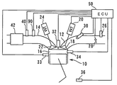
図1は、本発明の実施の形態1のシステムの構成を説明するための図である。本実施形態のシステムは、内燃機関10を備えている。内燃機関10は、複数の気筒を備える多筒式の機関である。図1には、それらの気筒のうちの1つを代表例として示している。
[Configuration of Embodiment 1]
FIG. 1 is a diagram for explaining the configuration of the system according to the first embodiment of the present invention. The system of this embodiment includes an
内燃機関10の個々の気筒には、吸気通路12と排気通路14が連通している。筒内16と吸気通路12との境界には、吸気弁18が設けられている。吸気弁18は、可変動弁機構(VVT)20によって駆動される。可変動弁機構20は、吸気弁18の開弁タイミングを変化させることができる。筒内16と排気通路14との境界には、排気弁22が配置されている。排気弁22は、VVT20と同様の機能を有するVVT24により駆動される。
An
吸気通路12には、吸入空気量Gaを検出するためのエアフロメータ26が組み付けられている。エアフロメータ26の下流には、スロットル弁28が配置されている。また、個々の気筒に通じる吸気ポートには、燃料噴射弁30が配置されている。更に、個々の気筒には、点火プラグ32と筒内圧センサ34とが組み付けられている。
An
内燃機関10は、クランク角を検知するためのクランク角センサ36を備えている。内燃機関10のシリンダブロックには、冷却水温THWを検知するための水温センサ38が組み付けられている。排気通路14は、排気空燃比を検知するための空燃比センサ40を備えている。空燃比センサ40の下流側には、排気ガスを浄化するための触媒42が配置されている。
The
本実施形態のシステムは、ECU(Electronic Control Unit)50を備えている。ECU50には、上述した各種のセンサ及びアクチュエータが接続されている。ECU50は、それらのセンサから送信される信号に基づいて、内燃機関10の状態を、適切に制御することができる。
The system of this embodiment includes an ECU (Electronic Control Unit) 50. The
[実施の形態1の特徴]
本実施形態のシステムは、筒内圧センサ34の出力Pに基づいて、排気ガス中のNOx濃度推定値[NOx]を算出する機能を有している。以下、本実施形態のシステムが、NOx濃度推定値[NOx]を算出する手法について説明する。
[Features of Embodiment 1]
The system of this embodiment has a function of calculating the estimated NOx concentration value [NOx] in the exhaust gas based on the output P of the in-
内燃機関10の筒内で発生するエネルギは、主として、出力トルクに変換される仕事エネルギQwと、筒内で消費される内部エネルギQi(筒内ガスを昇温させるエネルギ)に変換される。排気ガス中のNOxは、膨張行程において筒内ガスが過熱されることにより発生する。このため、NOxの発生量は、筒内で発生する内部エネルギと相関を有している。
The energy generated in the cylinder of the
混合気の燃焼に伴って生成される内部エネルギは、次式により求めることができる。但し、Vθ、Pθは、それぞれ、クランク角θにおける筒内容積V及び筒内圧力Pを意味するものとする。また、次式の積分期間は、点火クランク角θ1から燃焼終了クランク角θ2までとする。
Qi=∫Vθ・(dPθ/dθ)dθ ・・・(1)
The internal energy generated with the combustion of the air-fuel mixture can be obtained from the following equation. However, V θ and P θ mean the cylinder volume V and the cylinder pressure P at the crank angle θ, respectively. Further, the integration period of the following equation is from the ignition crank angle θ 1 to the combustion end crank angle θ 2 .
Qi = ∫V θ · (dP θ / dθ) dθ (1)
内燃機関10における空燃比は、原則として理論空燃比に制御される。このような前提の下では、混合気のポテンシャルエネルギは、吸入空気量Ga(負荷率KL)に比例する。従って、筒内で発生する内部エネルギの値、及び筒内で発生するNOxの量も、吸入空気量Ga(負荷率KL)に比例する。従って、排気ガスのNOx濃度推定値[NOx]は、上記(1)式により得られる内部エネルギを、KLで規格化した値に対して相関を示す。次式は、その関係を示したものである。但し、次式のαは比例係数である。
[NOx]=α・Qi/KL
=α・{∫Vθ・(dPθ/dθ)dθ}/KL ・・・(2)
In principle, the air-fuel ratio in the
[NOx] = α ・ Qi / KL
= Α ・ {∫V θ・ (dP θ / dθ) dθ} / KL (2)
図2は、内燃機関10の負荷率KLと、NOx排出量の実測値との関係を示す図である。上記(1)式では、内部エネルギQiが、負荷率KLと比例することを前提としている。しかしながら、負荷率KLが大きくなり、筒内で発生するエネルギが多量になると、壁面を伝って放出されるエネルギロス等の割合が大きくなり、負荷率KLの増加に対する内部エネルギの増加率が緩やかになる。図2に示す結果は、その現象が反映されたものであり、負荷率が40に達するまでは、NOx排出量がほぼKLに比例し、負荷率KLが40を超える領域では、負荷率KLが大きくなるに従って、NOx排出量の増加率が緩やかになることを表している。
FIG. 2 is a diagram showing the relationship between the load factor KL of the
図3は、負荷率KLが大きい領域でNOx排出量の増加率が緩やかになる傾向をNOx濃度推定値[NOx]に反映させるための補正係数f(kl)の一例を説明するための図である。図3に示す補正係数f(KL)は、KLが40以下の領域では基準値の1.0に維持され、KLが40を超える領域では、KLの増加に対して比例的に減少する。このf(KL)は、以下の式によって表すことができる。
f(KL)=(200−KL)/160
但し、f(KL)>1のときはf(KL)=1 ・・・(3)
FIG. 3 is a diagram for explaining an example of the correction coefficient f (kl) for causing the NOx concentration estimated value [NOx] to reflect the tendency that the increase rate of the NOx emission amount becomes gentle in the region where the load factor KL is large. is there. The correction coefficient f (KL) shown in FIG. 3 is maintained at the reference value of 1.0 in the region where KL is 40 or less, and decreases in proportion to the increase in KL in the region where KL exceeds 40. This f (KL) can be expressed by the following equation.
f (KL) = (200−KL) / 160
However, when f (KL)> 1, f (KL) = 1 (3)
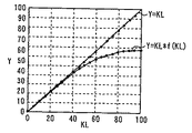
図4は、Y=KLの関係とY=KL*f(KL)の関係を、0≦KL≦100の範囲において表した図である。図4に示すように、Y=KL*f(KL)の曲線は、図2に示すNOx排出量の実測値と負荷率KLの関係に似た曲線となる。このように、上記の補正係数f(KL)は、KLに対して比例的な増加を示す変数に掛け合わせることにより、その変数の変化を、現実のNOx排出量の変化(図2に示す変化)に近似させることができる。従って、上記(1)式の結果(Qi)にf(KL)を掛け合わせれば、負荷率KLの下で現実に発生する内部エネルギを精度良く推定することができる。また、上記(2)式の結果([NOx])にf(KL)を掛け合わせれば、負荷率KLの下での現実のNOx濃度を精度良く推定することが可能である。 FIG. 4 is a diagram showing the relationship of Y = KL and the relationship of Y = KL * f (KL) in the range of 0 ≦ KL ≦ 100. As shown in FIG. 4, the curve of Y = KL * f (KL) is a curve similar to the relationship between the actual measurement value of NOx emission and the load factor KL shown in FIG. As described above, the correction coefficient f (KL) is multiplied by a variable showing a proportional increase with respect to KL, and the change of the variable is changed to the actual change of NOx emission (change shown in FIG. 2). ). Therefore, by multiplying the result (Qi) of the above equation (1) by f (KL), the internal energy actually generated under the load factor KL can be estimated with high accuracy. Further, by multiplying the result ([NOx]) of the above equation (2) by f (KL), it is possible to accurately estimate the actual NOx concentration under the load factor KL.
以下に示す演算式は、上記(2)式の積分項を、ECU50による処理(離散値の積算)に合わせてΣの項に置き換え、かつ、比例計数αを上記(3)式の補正係数f(KL)に置き換えたものである。
In the arithmetic expression shown below, the integral term in the above equation (2) is replaced with the term of Σ in accordance with the processing (integration of discrete values) by the

本実施形態のシステムは、内燃機関10の運転中に、上記(4)式に従ってNOx濃度推定値を算出する。具体的には、ECU50は、膨張行程毎に、その行程に先立って吸入された吸入空気量Gaに基づいて負荷率KLを算出する。また、ECU50は、膨張行程において、所定のクランク角Δθ毎に、筒内容積Vθ及び筒内圧力Pθを検出する。ECU50は、クランク角θとの関係で、個々の気筒の筒内容積Vθを定めたマップを記憶している。ここでは、そのマップに従って、クランク角センサ36の出力値に基づいて、筒内容積Vθが算出される。筒内圧力Pθについては、筒内圧センサ34の出力に基づいて検出される。
The system of the present embodiment calculates the NOx concentration estimated value according to the above equation (4) during operation of the
ECU50は、点火クランク角θ1から燃焼終了クランク角θ2まで、所定のクランク角Δθ毎に、Σ{Vθ・(dPθ/dθ)Δθ}の積算を進行させる。その結果として得られた積算値に、負荷率KLに基づく規格化と、補正係数f(KL)による補正とが施されることにより、上記(4)式によるNOx濃度推定値[NOx]が算出される。
The
上記(4)式の推定では、NOx濃度の基礎データとして、筒内圧Pが用いられている。このような推定の手法によれば、点火時期の変動や、ノックの発生に起因して、筒内での混合気の燃焼状態が変化した場合に、その変化をNOx濃度推定値[NOx]に反映させることができる。このため、上述した推定の手法によれば、内燃機関10の運転状態の変化に関わらず、常に高い精度でNOx濃度を推定する機能を実現することができる。
In the estimation of the above equation (4), the in-cylinder pressure P is used as basic data of the NOx concentration. According to such an estimation method, when the combustion state of the air-fuel mixture in the cylinder changes due to fluctuations in the ignition timing or occurrence of knocking, the change is made to the NOx concentration estimated value [NOx]. It can be reflected. For this reason, according to the estimation method described above, it is possible to realize the function of always estimating the NOx concentration with high accuracy regardless of the change in the operating state of the
図5は、本実施形態のシステムが算出したNOx濃度推定値[NOx]と、内燃機関10の排気ガス中のNOx濃度の実測値との相関を示した図である。図5に示す各点は、異なる条件下で得られたNOx濃度推定値[NOx]と、NOx濃度の実測値との組みをプロットしたものである。ここで、「異なる条件」とは、機関回転数NE及び負荷率KLが異なることを意味する。但し、混合気の空燃比は理論空燃比に制御されているものとする。
FIG. 5 is a diagram showing a correlation between the estimated NOx concentration value [NOx] calculated by the system of the present embodiment and the actual measured value of the NOx concentration in the exhaust gas of the
図5に示す結果は、上記(4)式により算出されたNOx濃度推定値[NOx]が、あらゆる運転条件下で、NOx濃度の実測値に対して極めて高い相関を示すことを表している。このように、本実施形態のシステムによれば、あらゆる運転状況の下で、NOx濃度の実測値と精度良く一致するNOx濃度推定値[NOx]を算出することが可能である。 The results shown in FIG. 5 indicate that the NOx concentration estimated value [NOx] calculated by the above equation (4) shows a very high correlation with the measured value of the NOx concentration under all operating conditions. As described above, according to the system of the present embodiment, it is possible to calculate the NOx concentration estimated value [NOx] that accurately matches the actually measured value of the NOx concentration under any operating conditions.
ところで、上述した実施の形態1においては、ECU50が、(4)式におけるΣ{Vθ・(dPθ/dθ)Δθ}の積算処理を行うことにより、前記第1の発明における「内部エネルギ相関値算出手段」が実現されている。また、ECU50が、その結果に対して、KLによる規格化と、f(KL)による補正とを施すことにより前記第1の発明における「NOx濃度推定手段」が実現されている。
By the way, in the first embodiment described above, the
また、上述した実施の形態1においては、エアフロメータ26が前記第2又は第3の発明における「吸入空気量検出手段」に相当している。更に、ECU50が、(4)式におけるΣ{Vθ・(dPθ/dθ)Δθ}の積算処理を行うことにより前記第2の発明における「NOx量算出手段」が実現されている。更に、ECU50が、その積算処理の結果に対してKLによる規格化を施すことにより前記第2の発明における「規格化手段」が、f(KL)による補正を施すことにより前記第3の発明における「補正手段」が、それぞれ実現されている。
In the first embodiment described above, the
実施の形態2.
次に、本発明の実施の形態2について説明する。本実施形態のシステムは、図1に示す構成において、ECU50に、後述する(5)式に従ってNOx濃度推定値[NOx]を算出させることにより実現することができる。
Next, a second embodiment of the present invention will be described. The system of the present embodiment can be realized by causing the
上述した実施の形態1では、内燃機関10が、空燃比が理論空燃比に制御された状態で作動することを前提としている。しかしながら、内燃機関10においては、燃料の増量補正や減量補正が要求されることがある。そして、内燃機関10の空燃比は、それらの要求に応じた燃料制御が実行されることにより、必然的に理論空燃比から外れた値となる。
In the first embodiment described above, it is assumed that the
排気ガス中のNOxは、混合気中に存在する酸素が多量であるほど、つまり、空燃比がリーンであるほど発生し易い。このため、空燃比が理論空燃比から外れる領域においてNOx濃度を正確に推定するためには、空燃比の影響を、NOx濃度推定値[NOx]に反映させることが必要である。 NOx in the exhaust gas is more likely to be generated as the amount of oxygen present in the air-fuel mixture increases, that is, as the air-fuel ratio becomes leaner. Therefore, in order to accurately estimate the NOx concentration in a region where the air-fuel ratio deviates from the stoichiometric air-fuel ratio, it is necessary to reflect the influence of the air-fuel ratio on the NOx concentration estimated value [NOx].
以下に示す演算式(5)は、上記の要求に応えるためのものである。具体的には、式(5)は、上記(4)式の右辺に、空燃比補正係数λを掛け合わせたものである。但し、空燃比補正係数λは、排気空燃比A/Fの実測値と、理論空燃比(ここでは「14.5」とする)との比(λ=(A/F)/14.5)とする。 The following arithmetic expression (5) is for meeting the above requirements. Specifically, Equation (5) is obtained by multiplying the right side of Equation (4) by the air-fuel ratio correction coefficient λ. However, the air-fuel ratio correction coefficient λ is a ratio between the measured value of the exhaust air-fuel ratio A / F and the theoretical air-fuel ratio (here, “14.5”) (λ = (A / F) /14.5). And
ECU50は、空燃比センサ40の出力により、排気空燃比A/Fを実測することができる。また、上記の空燃比補正係数λは、空燃比A/Fが理論空燃比に一致する場合に基準値1.0となり、A/Fがリーンになるほど大きな値に、また、A/Fがリッチになるほど小さな値になる。このため、上記(5)式によれば、空燃比がNOxの発生量に与える影響を、適切にNOx濃度推定値[NOx]に反映させることができる。従って、本実施形態のシステムによれば、空燃比が理論空燃比から外れる状況下でも、NOx濃度推定値[NOx]を極めて精度良く算出することができる。
The
尚、上述した実施の形態2においては、空燃比センサ40が前記第4の発明における「空燃比検出手段」に相当している。また、ECU50が、(5)式に示すλの積算処理を行うことにより前記第4の発明における「補正手段」が実現されている。
In the second embodiment described above, the air-
実施の形態3.
次に、図6乃至図8を参照して、本発明の実施の形態3について説明する。本実施形態のシステムは、図1に示す構成に、吸気管圧力Pmを検知する圧力センサを加えると共に、ECU50に、後述する(6)式に従ってNOx濃度推定値[NOx]を算出させることにより実現することができる。
Embodiment 3 FIG.
Next, Embodiment 3 of the present invention will be described with reference to FIGS. The system of the present embodiment is realized by adding a pressure sensor for detecting the intake pipe pressure Pm to the configuration shown in FIG. 1 and causing the
筒内で発生するNOxの量は、筒内ガスが高温になるほど多量になり易い。筒内には、吸気行程において吸入された新気と共に、筒内に残留した残留ガス(EGRガスを含む)とが存在している。筒内で発生したエネルギは、残留ガスの昇温によっても消費される。このため、残留ガスが多量であるほど、筒内ガスの温度は上昇しにくく、その結果、NOxの生成量が少量となる。 The amount of NOx generated in the cylinder tends to increase as the temperature of the in-cylinder gas increases. In the cylinder, there is residual gas (including EGR gas) remaining in the cylinder as well as fresh air sucked in the intake stroke. The energy generated in the cylinder is also consumed by the temperature rise of the residual gas. For this reason, as the residual gas increases, the temperature of the in-cylinder gas hardly increases, and as a result, the amount of NOx generated decreases.
上述した実施の形態1及び2は、筒内に残留する既燃ガスの割合が大きく変動しないことを前提としてNOx濃度推定値[NOx]を算出している。しかしながら、内燃機関10においては、VVT20,24の機能によってバルブオーバーラップが変化すると、筒内の残留ガスの割合に有意な変化が生ずる。このため、上述した実施の形態1又は2における手法では、VVT20,24がバルブオーバーラップを変化させた場合に、NOx濃度の推定精度が低下する事態が生じ得る。
Embodiments 1 and 2 described above calculate the NOx concentration estimated value [NOx] on the assumption that the ratio of burned gas remaining in the cylinder does not vary greatly. However, in the
図6は、VVTの作動に伴う残留ガス量の変化が、(4)式(実施の形態1)によるNOx濃度推定値[NOx]に与える影響を示す結果である。図6に示す各点は、異なる条件下で算出されたNOx濃度推定値[NOx]と、NOx濃度の実測値との組みをプロットしたものである。図6中に「吸気弁進角小」として示した点は、吸気弁18の進角量が少なくなるように、つまり、バルブオーバーラップが小さくなるようにVVT20を作動させた場合の結果である。他方、図6中に「吸気弁進角大」として示した点は、吸気弁18の進角量が多くなるように、つまり、バルブオーバーラップが大きくなるようにVVT20を作動させた場合の結果である。
FIG. 6 is a result showing the influence of the change in the residual gas amount accompanying the operation of the VVT on the NOx concentration estimated value [NOx] according to the equation (4) (Embodiment 1). Each point shown in FIG. 6 is a plot of a set of an estimated NOx concentration value [NOx] calculated under different conditions and an actual measured value of NOx concentration. The point indicated as “small intake valve advance angle” in FIG. 6 is the result when the
図6に示す結果は、進角量が少なく残留ガス(内部EGRガス)量が少ない状況下では、現実には、その影響でNOxが多量に発生しているのに対して、(4)式による[NOx]値が過小になっていることを表している。また、この結果は、進角量が多く残留ガス量が多い状況下では、現実には、その影響でNOx発生量が少なくなるのに対して、(4)式では過大な[NOx]値が算出されることを表している。 The results shown in FIG. 6 show that in the situation where the amount of advance angle is small and the amount of residual gas (internal EGR gas) is small, in reality, a large amount of NOx is generated due to the influence, but equation (4) This indicates that the [NOx] value by is too small. In addition, this result shows that in the situation where the amount of advance is large and the amount of residual gas is large, the amount of NOx generated is actually reduced due to the influence, whereas in equation (4), an excessive [NOx] value is It is calculated.
本実施形態のシステムは、筒内の残留ガス量を、NOx濃度推定値[NOx]に反映させることにより、上記の理由に起因する推定誤差を十分に抑制する点に特徴を有している。以下、残留ガス量を[NOx]に反映させるための手法を説明する。 The system of this embodiment is characterized in that the estimation error due to the above reason is sufficiently suppressed by reflecting the amount of residual gas in the cylinder in the NOx concentration estimated value [NOx]. Hereinafter, a method for reflecting the residual gas amount in [NOx] will be described.
図7は、吸気弁18の進角量と、吸気管圧力Pmとの関係を説明するための図である。図7に示す複数の実線は、それぞれ、機関回転数NE及び負荷率KLを一定として吸気弁18の進角量(バルブオーバーラップ)を変化させた場合に得られた複数の結果(点)を結んだものである。これらの実線は、それぞれ、バルブオーバーラップと吸気管圧力Pmとが互いに相関していることを示している。より具体的には、図7に示す複数の実線は、バルブオーバーラップが大きくなり、残留ガス量が多量になるほど、吸気管圧力Pmが高くなることを示している。このため、吸気管圧力Pmは、残留ガス量の代用特性値として用いることが可能である。
FIG. 7 is a view for explaining the relationship between the advance amount of the
以下に示す演算式(6)は、吸気管圧力Pmを用いて、残留ガス量の影響をNOx濃度推定値[NOx]に反映させるための式である。但し、(6)式におけるτは、燃料噴射弁30に指令する燃料噴射時間である。
An arithmetic expression (6) shown below is an expression for reflecting the influence of the residual gas amount on the NOx concentration estimated value [NOx] using the intake pipe pressure Pm. However, τ in the equation (6) is a fuel injection time commanded to the
上記(6)式は、実質的には、(5)式における補正係数f(KL)を、Pmをパラメータとするf(Pm)に置き換えたものである。すなわち、(5)式における(1/KL)*λは、以下に示すように展開することができる。
(1/KL)*λ
=(1/KL)*(A/F)/14.5 ・・・(7)
The above equation (6) is substantially obtained by replacing the correction coefficient f (KL) in equation (5) with f (Pm) using Pm as a parameter. That is, (1 / KL) * λ in equation (5) can be expanded as shown below.
(1 / KL) * λ
= (1 / KL) * (A / F) /14.5 (7)
KLは、吸入空気量Gaの相関値であり、AはGaを意味するから、(1/KL)*Aは係数に置き換えることができる。この係数と14.5を一つの係数βで表せば、(7)式の関係は、以下のように表すことができる。
(1/KL)*λ=β/F ・・・(8)
Since KL is a correlation value of the intake air amount Ga and A means Ga, (1 / KL) * A can be replaced with a coefficient. If this coefficient and 14.5 are expressed by one coefficient β, the relationship of the equation (7) can be expressed as follows.
(1 / KL) * λ = β / F (8)
Fは燃料噴射量であるから、τに置き換えることができる。従って、(5)式における(1/KL)*λは、(6)式におけるβ*(1/τ)と等価である。このため、(6)式は実質的には、補正係数fのパラメータが、負荷率KLから吸気管圧力Pmに置き換えられている点を除いて、(5)式と同一である。 Since F is the fuel injection amount, it can be replaced with τ. Therefore, (1 / KL) * λ in equation (5) is equivalent to β * (1 / τ) in equation (6). For this reason, the equation (6) is substantially the same as the equation (5) except that the parameter of the correction coefficient f is replaced with the intake pipe pressure Pm from the load factor KL.
補正係数f(Pm)は、図3に示すf(KL)と同様に、吸気管圧力Pmが低い領域では基準値1.0を維持し、吸気管圧力Pmが大きい領域では、Pmが大きくなるほど最小値0に向かって減少する。吸気管圧力Pmは、上述した通り、残留ガス量が多いほど高い値となる(図7参照)。従って、補正係数f(Pm)によれば、残留ガス量が多く、現実のNOx量が少なくなり易いほど、NOx濃度推定値[NOx]を小さく補正することができる。
As with f (KL) shown in FIG. 3, the correction coefficient f (Pm) maintains the reference value 1.0 in the region where the intake pipe pressure Pm is low, and the Pm increases as the intake pipe pressure Pm increases. It decreases toward the
図8は、上記(6)式に従って算出したNOx濃度推定値[NOx]と、NOx濃度の実測値との相関を示した図である。図8に示す各点は、機関回転数NE及び負荷率KLに加えて、吸気弁18のVVT20の状態をも変化させて得た、NOx濃度推定値[NOx]とNOx濃度の実測値との組み合わせをプロットしたものである。図8に示すように、上記(6)式によれば、VVT20の状態変化の影響を受けることなく、NOxの実測値に対して常に高い相関を示すNOx濃度推定値[NOx]を算出することができる。このため、本実施形態のシステムによれば、残留ガス量の多少に関わらず、排気ガスのNOx濃度を正確に推定することができる。
FIG. 8 is a diagram showing the correlation between the estimated NOx concentration value [NOx] calculated according to the above equation (6) and the actual measured value of NOx concentration. Each point shown in FIG. 8 is obtained by changing the state of the
ところで、上述した実施の形態3では、残留ガスの影響を、吸気管圧力Pmを用いてNOx濃度推定値[NOx]に反映させることとしているが、その手法はこれに限定されるものではない。すなわち、筒内の残留ガス量は、例えば、吸気行程圧力と、排気行程圧力とを基礎データとすることで、公知の手法(例えば筒内DJ手法)により算出することができる。残留ガス量が算出できれば、吸気管圧力Pmと同様の特性、つまり、残留ガス量が多いほど大きな値となり、かつ、負荷率KLが大きいほど大きな値となる特性を示す他のパラメータを設定することができる。このパラメータを、Pmに置き換えて(6)式の演算を行うことによっても、残留ガス量の影響を[NOx]に反映させることは可能である。 In the third embodiment described above, the effect of residual gas is reflected in the NOx concentration estimated value [NOx] using the intake pipe pressure Pm, but the method is not limited to this. That is, the residual gas amount in the cylinder can be calculated by a known method (for example, an in-cylinder DJ method) by using, for example, the intake stroke pressure and the exhaust stroke pressure as basic data. If the residual gas amount can be calculated, other parameters that show the same characteristics as the intake pipe pressure Pm, that is, the larger the residual gas amount, and the larger the load factor KL, the larger the parameter. Can do. The effect of the residual gas amount can be reflected in [NOx] by replacing this parameter with Pm and performing the calculation of equation (6).
また、上述した実施の形態3では、補正係数f(Pm)を用いて、負荷率KLの影響と共に残留ガス量の影響をNOx濃度推定値[NOx]に反映させることとしているが、その手法はこれに限定されるものではない。すなわち、NOx濃度推定値[NOx]の精度を高めるうえでは、残留ガス量が多いほど、[NOx]が小さく補正されれば十分である。従って、残留ガス量が判る場合には、例えば、(5)式の右辺分母に残留ガス量を反映させることで上記の機能を実現することとしてもよい。 In the third embodiment described above, the correction coefficient f (Pm) is used to reflect the influence of the residual gas amount together with the influence of the load factor KL on the NOx concentration estimated value [NOx]. It is not limited to this. That is, in order to increase the accuracy of the NOx concentration estimated value [NOx], it is sufficient that [NOx] is corrected to be smaller as the residual gas amount is larger. Therefore, when the residual gas amount is known, for example, the above function may be realized by reflecting the residual gas amount in the right side denominator of the equation (5).
また、上述した実施の形態3では、残留ガス量が変化する原因が、バルブオーバーラップの変化に限定されているが、その原因はこれに限定されるものではない。例えば、排気ガスを吸気系に還流させるEGR機構を備える内燃機関においては、残留ガス量が、そのEGR機構の状態に応じて変化することがある。本実施形態の手法によれば、残留ガス量の変化が、如何なる原因により生じたかに関わらず、常にその影響を精度良くNOx濃度推定値[NOx]に反映させることができる。 In the third embodiment described above, the cause of the change in the residual gas amount is limited to the change in the valve overlap, but the cause is not limited to this. For example, in an internal combustion engine that includes an EGR mechanism that recirculates exhaust gas to the intake system, the amount of residual gas may vary depending on the state of the EGR mechanism. According to the method of the present embodiment, regardless of what causes the change in the residual gas amount, the influence can always be accurately reflected in the NOx concentration estimated value [NOx].
また、上述した実施の形態3においては、吸気管圧力Pmを、吸気圧センサにより検知することとしているが、その検知の手法はこれに限定されるものではない。例えば、エアフロメータ26によって検出される吸入空気量Gaや、クランク角センサ36によって検知される機関回転数NE等に基づいて、公知の手法で吸気管圧力Pmを推定することとしてもよい。
In the third embodiment described above, the intake pipe pressure Pm is detected by the intake pressure sensor, but the detection method is not limited to this. For example, the intake pipe pressure Pm may be estimated by a known method based on the intake air amount Ga detected by the
尚、上述した実施の形態3においては、吸気圧センサが前記第5の発明における「残留ガス量相関値検知手段」に相当している。また、ECU50が、(6)式における補正係数f(Pm)の積算処理を行うことにより前記第5の発明における「補正手段」が実現されている。
In the third embodiment described above, the intake pressure sensor corresponds to the “residual gas amount correlation value detecting means” in the fifth aspect of the invention. Further, the “correction means” in the fifth aspect of the present invention is realized by the
また、上述した実施の形態3においては、エアフロメータ26が、前記第6の発明における吸入空気量検出手段に相当している。また、ECU50に、残留ガス量を算出させることにより、前記第5の発明における「残留ガス量相関値検知手段」を実現することができる。更に、ECU50に、残留ガス量が多いほど大きな値となり、かつ、負荷率KLが大きいほど大きな値となるパラメータを設定させ、Pmをそのパラメータに置き換えて(6)式の演算を実行させることにより前記第6の発明における「補正手段」を実現することができる。
In the third embodiment described above, the
実施の形態4.
[実施の形態4の特徴]
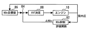
次に、図9及び図10を参照して、本発明の実施の形態4について説明する。図9は、本実施形態において、ECU50が実行する制御の内容を説明するためのブロック図である。図9に示すように、本実施形態では、ECU50の内部に、NOx算出部52、MFB算出部54、及びSA決定部56が形成される。これらは、何れも、ECU50が、その内部に記憶されている制御プログラムを実行することにより実現される。
Embodiment 4 FIG.
[Features of Embodiment 4]
Next, a fourth embodiment of the present invention will be described with reference to FIG. 9 and FIG. FIG. 9 is a block diagram for explaining the contents of control executed by the
NOx算出部52は、上述した実施の形態1乃至3の何れかの手法でNOx濃度推定値[NOx]を算出する部分である。MFB算出部54は、以下に説明する手法により、筒内の燃焼状態の特性値であるMFBを算出する部分である。MFBは、点火の実行後、クランク角が特定クランク角に達するまでに生じた熱量Q1と、燃焼終了クランク角(本実施形態ではATDC60°CAとする)に達するまでに生じた発熱量Q@ATDC60との比(Q1/ Q@ATDC60)で表される。
The
内燃機関10が発生するトルクは、負荷率KLや空燃比A/Fが同じでも、点火時期が異なれば異なった値となる。このため、内燃機関10の点火時期は、出力特性を向上させる観点からは、最も効率的にトルクを発生させるクランク角に制御することが望ましい。つまり、出力向上の観点からは、点火進角値SAを、上記のクランク角を実現する値(MBT)に制御することが望ましい。
Even if the load factor KL and the air-fuel ratio A / F are the same, the torque generated by the
本実施形態において、MFB算出部54は、特に、上記の特定クランク角を上死点後(ATDC)8°CAとしてMFBを算出する。以下、この点が明確になるように、本実施形態におけるMFBを、「MFB@ATDC8」とする。以下に示す(9)式は、MFB算出部54によって算出されるMFB@ATDC8の演算式である。
MFB@ATDC8=Q@ATDC8/Q@ATDC60 ・・・(9)
In the present embodiment, the
MFB @ ATDC8 = Q @ ATDC8 / Q @ ATDC60 (9)
上記(9)式(特に、ATDC8°CAを第1のクランク角とすること)は、内燃機関10の特性に合わせて設定したものである。本実施形態において、この式(9)により算出されるMFB@ATDC8は、内燃機関10の点火進角値SAとMBTとの一致程度に対して相関を有している。より具体的には、上記のMFB@ATDC8は、内燃機関10の点火進角値SAがMBTに近づくに連れて0.5に近づき、両者が一致する状況下で0.5となる。このため、MFB@ATDC8は、本実施形態において、点火進角値SAとMBTとの一致度合いを表す特性値として用いることができる。
The above equation (9) (particularly, setting ATDC 8 ° CA as the first crank angle) is set in accordance with the characteristics of the
SA決定部56は、NOx濃度推定値[NOx]とMFB@ATDC8とに基づいて、内燃機関10において用いるべき点火進角値SAを決定する部分である。SA決定部56は、より具体的には、第1に、次式(10)に従って評価関数Jを算出する。但し、次式中「A」は、内燃機関10の運転状態に応じて適宜決定される重み付け係数である。また、次式中「a」は、内燃機関10が目標とするNOx濃度、つまり、[NOx]の目標値である。
J=A×(MFB@ATDC8−0.5)2+(1−A)×([NOx]−a)2 ・・・(10)
The
J = A × (MFB @ ATDC8 −0.5) 2 + (1−A) × ([NOx] −a) 2 (10)
(10)式によって算出される評価値Jは、MFB@ATDC8が0.5に近いほど、つまり、点火進角値SAがMBTに近いほど小さな値となり、かつ、[NOx]が目標値aに近いほど小さな値となる。但し、点火進角値SAがMBTに近い領域では、それらが近づくに従って、NOxが増える傾向がある。このため、点火進角値SAを徐々にMBTに近づけていった場合、評価値Jは、一旦減少した後、増加に転じる傾向を示す。 The evaluation value J calculated by the equation (10) becomes smaller as MFB @ ATDC8 is closer to 0.5, that is, the ignition advance value SA is closer to MBT, and [NOx] becomes the target value a. The closer it is, the smaller the value. However, in the region where the ignition advance value SA is close to MBT, NOx tends to increase as they approach. For this reason, when the ignition advance value SA is gradually brought closer to the MBT, the evaluation value J tends to increase after decreasing once.
内燃機関10においては、高い出力効率が望まれると同時に、NOx排出量が少ないことも望まれる。上記の評価値Jは、MFB@ATDC8及び [NOx]の双方が、バランス良くそれぞれの目標値(最適値)に近づいた際に最小の値となる。従って、出力効率に関する要求とNOx排出量に関する要求とを高いレベルで両立させるうえでは、評価値Jが最小値となるような点火進角値SAを設定することが望ましい。
In the
本実施形態において、SA決定部56は、第2に、上記(10)式によって算出される評価値Jを最小とする点火進角値SAを探索する。具体的には、点火進角値SAを変化させながら評価値Jを算出し、その値Jを最小とする最適なSAを探索する。そして、SA決定部56は、このようにして探索したSAを、内燃機関10に対する指令値として保持する。以上の処理により、本実施形態のシステムは、内燃機関10に対して、優れた排気エミッション特性と、優れた出力特性とを共に付与することができる。
In the present embodiment, the
[実施の形態4における具体的処理]
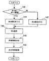
図10は、本実施形態において、ECU50が実行するルーチンのフローチャートである。図10に示すルーチンでは、先ず、内燃機関10の運転条件が読み込まれる(ステップ100)。ここでは、具体的には、機関回転数NE、負荷率KL(吸入空気量Ga)に加えて、実施の形態1乃至3の何れかの手法で算出された[NOx]、並びに公知の手法で算出されたMFBが読み込まれる。
[Specific Processing in Embodiment 4]
FIG. 10 is a flowchart of a routine executed by the
次に、NOx濃度の目標値aが選択される(ステップ102)。内燃機関10が目標とするNOx濃度は、必ずしも一定ではない。すなわち、内燃機関10に要求される様々な要求にバランス良く応えるためには、NOx濃度の目標値aは、内燃機関10の運転状態に応じて適宜変化させることが望ましい。本実施形態において、ECU50は、内燃機関10の運転状態との関係で目標値aを定めたマップを記憶している。ここでは、そのマップに従って目標値aが選択される。
Next, the NOx concentration target value a is selected (step 102). The target NOx concentration of the
次に、重み付け係数Aが決定される(ステップ104)。内燃機関10において、優れた出力効率を得ることの重要性と、優れたエミッション特性を得ることの重要性は、常に一定ではない。例えば、加速が要求される状況下では、出力効率の要求を、エミッション特性の要求に優先することが望ましい。また、定常運転時には、その逆の優先設定をすることが望ましい。ECU50は、上記の観点から、内燃機関10の運転状態との関係で、重み付け係数Aを定めたマップを記憶している。このマップは、出力効率が優先される状況下ほど重み付け係数Aが最大値1.0に近づき、エミッション特性が優先される状況下ほど、重み付け係数Aが最小値0に近づくように設定されている。本ステップ104では、このマップに従って重み付け係数Aが決定される。
Next, the weighting coefficient A is determined (step 104). In the
次に、点火進角値SAの初期値SA0が設定される(ステップ106)。初期値SA0は、十分に小さな値に設定される。より具体的には、上記(10)式による評価値Jを最小値とするSAに対して、MBTの反対側に位置することが明らかな値に設定される。 Next, an initial value SA0 of the ignition advance value SA is set (step 106). The initial value SA0 is set to a sufficiently small value. More specifically, it is set to a value that is clearly located on the opposite side of the MBT with respect to the SA having the minimum evaluation value J according to the above equation (10).
次に、上記(10)式に従って、評価値Jが算出される(ステップ108)。次いで、今回の処理サイクルで算出されたJが、前回のサイクルで算出されたJに比して小さいか否かが判別される(ステップ110)。 Next, the evaluation value J is calculated according to the above equation (10) (step 108). Next, it is determined whether or not J calculated in the current processing cycle is smaller than J calculated in the previous cycle (step 110).
評価値Jには、初期化処理により十分に大きな値が設定される。このため、評価値Jが初めて演算されたサイクルでは、ステップ110の条件が成立する。同様に、点火進角値SAが、初期値SA0の近傍にある間は、その条件の成立が判定される。この場合は、点火進角値SAが、所定値dSAだけ大きく更新される(ステップ112)。その後、再びステップ108の処理が実行される。
The evaluation value J is set to a sufficiently large value by the initialization process. For this reason, in the cycle in which the evaluation value J is calculated for the first time, the condition of
上記の処理が繰り返されると、やがては、評価値Jの変化が減少から増加に転じる。この反転が生ずると、ステップ110の条件が不成立となる。この場合、その時点で設定されている点火進角値SAが保持される(ステップ114)。
If the above process is repeated, the change in the evaluation value J will eventually increase from a decrease to an increase. When this inversion occurs, the condition of
以上の処理によれば、内燃機関10の運転状態に応じて重み付け係数A及びNOx目標値aをそれぞれ自由に設定することができる。更に、この処理によれば、それらの設定の下で、評価値Jを最小とする点火進角値SAを保持することができる。このため、本実施形態のシステムによれば、内燃機関10の出力特性及びエミッション特性を、内燃機関10の運転状況に応じた最適なバランスで両立させることができる。
According to the above processing, the weighting coefficient A and the NOx target value a can be freely set according to the operating state of the
ところで、上述した実施の形態4においては、内燃機関10の特性に合わせて、MFB@ATDC8を、点火進角値とMBTとの一致度合いを表す特性値としている。従って、異なる特性を示す内燃機関に対しては、ATDC8°CAとは異なるクランク角を特定クランク角としてMFBを算出することとしてもよい。尚、この点は、以下に説明する他の実施形態においても同様である。
By the way, in Embodiment 4 described above, MFB @ ATDC8 is set to a characteristic value representing the degree of coincidence between the ignition advance value and the MBT in accordance with the characteristics of the
尚、上述した実施の形態4においては、MFB@ATDC8が前記第8の発明における「出力効率指標」に相当していると共に、ECU50が、MFB@ATDC8を算出することにより前記第8の発明における「出力効率指標算出手段」が実現されている。また、ここでは、(10)式における(MFB@ATDC8−0.5)が前記第8の発明における「指標偏差」に相当していると共に、ECU50がその演算を行うことにより前記第8の発明における「指標偏差算出手段」が実現されている。また、(10)式における([NOx]−a)が前記第8の発明における「濃度偏差」に相当していると共に、ECU50がその演算を行うことにより前記第8の発明における「濃度偏差算出手段」が実現されている。更に、ECU50が、上記ステップ108の処理を実行することにより前記第8の発明における「評価値算出手段」が、上記ステップ110〜114の処理を実行することにより前記第8の発明における「点火時期制御手段」が、それぞれ実現されている。
In the above-described fourth embodiment, MFB @ ATDC8 corresponds to the “output efficiency index” in the eighth invention, and
また、上述した実施の形態4においては、ECU50が、ステップ104の処理を実行することにより前記第9の発明における「重み係数変更手段」が実現されている。
In the fourth embodiment described above, the “weight coefficient changing means” according to the ninth aspect of the present invention is realized by the
実施の形態5.
次に、図11を参照して本発明の実施の形態5について説明する。図11は、本実施形態において、ECU50が実行する制御の内容を説明するためのブロック図である。図11に示す構成要素は、何れも、ECU50が、その内部に記憶している制御プログラムを実行することにより実現される。
Embodiment 5 FIG.
Next, a fifth embodiment of the present invention will be described with reference to FIG. FIG. 11 is a block diagram for explaining the contents of the control executed by the
図11に示すように、本実施形態においては、ECU50の内部に、NOx抑制部62が形成される。NOx抑制部62は、NOx補正値KNOx=γ・ΔNOxを算出するためのブロックである。NOx抑制部62は、具体的には、以下の処理を実行する。
i)上述した実施の形態1乃至3の何れかの手法でNOx濃度推定値[NOx]を算出する。
ii)算出した[NOx]と、NOx濃度の目標値aとの差ΔNOx(=[NOx]−a)を算出する。
iii)上記の差ΔNOxに定数γを掛け合わせてNOx補正値KNOx=γ・ΔNOxを算出する。
As shown in FIG. 11, in the present embodiment, a
i) The NOx concentration estimated value [NOx] is calculated by the method of any one of the first to third embodiments described above.
ii) A difference ΔNOx (= [NOx] −a) between the calculated [NOx] and the target value a of the NOx concentration is calculated.
iii) Multiplying the difference ΔNOx by a constant γ, the NOx correction value KNOx = γ · ΔNOx is calculated.
NOx補正値KNOxは、NOx濃度推定値[NOx]が目標値aに対して過大であるほど大きな値となる係数である。ECU50の内部で、NOx補正値KNOxは、図11に示すように第1減算部64に供給される。第1減算部64には、MFB@ATDC8の最適値である0.5が供給されている。第1減算部64は、その0.5からNOx補正値KNOxを減じた値(以下、「第1指令値OUT64」とする)を、後段の第2減算部66に供給する。
The NOx correction value KNOx is a coefficient that increases as the NOx concentration estimated value [NOx] is excessive with respect to the target value a. Inside the
第2減算部66には、MFB演算部68からMFB@ATDC8が供給されている。MFB演算部68は、実施の形態4において説明した上記(9)式に従って、公知の手法によりMFB@ATDC8を算出するブロックである。第2減算部66は、第1減算部64から供給された第1指令値OUT64
からMFB@ATDC8を減じた値(以下、「第2指令値OUT66」とする)をPI制御部70に供給する。PI制御部70に供給される第2指令値OUT66は、次式により表すことができる。
OUT66=OUT64−MFB@ATDC8=0.5−KNOx−MFB@ATDC8 ・・・(11)
The second subtraction unit 66 is supplied with MFB @ ATDC8 from the
A value obtained by subtracting MFB @ ATDC8 (hereinafter referred to as “second command value OUT 66 ”) is supplied to the
OUT 66 = OUT 64 -MFB @ ATDC8 = 0.5 -KNOx -MFB @ ATDC8 (11)
(11)式により算出される第2指令値OUT66は、MFB@ATDC8が、第1指令値OUT64より小さい場合には正の値となる。つまり、第2指令値OUT66は、第1指令値OUT64が意味する燃焼割合に対してMFB@ATDC8が過小である場合に正の値となり、他方、MFB@ATDC8が過大である場合に負の値となる。 The second command value OUT 66 calculated by the equation (11) is a positive value when MFB @ ATDC8 is smaller than the first command value OUT 64 . That is, the second command value OUT 66 is a positive value when MFB @ ATDC8 is too small with respect to the combustion ratio implied by the first command value OUT 64 , and is negative when MFB @ ATDC8 is excessive. It becomes the value of.
PI制御部70は、第2指令値OUT66の比例項Pと積分項Iを算出し、それらの和を進角補正値ΔSAとして算出するブロックである。PI制御部70によって算出された進角補正値ΔSAは、加算部72に供給される。加算部72には、また、点火時期モデル演算部74から基本進角値SABが供給されている。点火時期モデル演算部74は、機関回転数NE及び機関負荷KLを基礎として、内燃機関10の運転状態に適合した点火進角値を基本進角値SABとして算出するブロックである。加算部72は、基本進角値SABに進角補正値ΔSAを加えた値を最終的な点火進角値SAとして内燃機関10に供給する。内燃機関10は、このようにして算出された点火進角値SAで各気筒の点火時期を決定する。
The
点火進角値SAは、進角補正値ΔSAが0であれば基本進角値SABと一致する。そして、点火進角値SAは、ΔSAが正であればSABより進角側の値となり、ΔSAが負であればSABに比して遅角側の値となる。進角補正値ΔSAは、第2指令値OUT66が正であれば正方向に更新され、第2指令値OUT66が負であれば負方向に更新される。 The ignition advance value SA matches the basic advance value SAB if the advance correction value ΔSA is zero. The ignition advance value SA is a value on the advance side from SAB if ΔSA is positive, and a value on the retard side compared to SAB if ΔSA is negative. Advance correction value ΔSA is second command value OUT 66 is updated if any in the positive direction positive, second command value OUT 66 is updated in the negative direction if it is negative.
第2指令値OUT66は、上述した通り、第1指令値OUT64に対してMFB@ATDC8が過小である場合に正となる。この場合、進角補正値ΔSAが正方向に更新され、点火進角値SAが進角側に修正される。その結果、燃焼の速度が増してMFB@ATDC8が第1指令値OUT64に近づけられる。反対に、第1指令値OUT64に対してMFB@ATDC8が過大である場合は、第2指令値OUT66が負となり、点火進角値SAが遅角側に修正される。このように、図11に示すシステムによれば、MFB@ATDC8が第1指令値OUT64に近づくように内燃機関10の点火進角値SAを制御することができる。
As described above, the second command value OUT 66 is positive when the MFB @ ATDC8 is too small with respect to the first command value OUT 64 . In this case, the advance correction value ΔSA is updated in the positive direction, and the ignition advance value SA is corrected to the advance side. As a result, the rate of combustion MFB @ ATDC8 is brought close to the first command value OUT 64 increases. On the other hand, when MFB @ ATDC8 is excessive with respect to the first command value OUT 64 , the second command value OUT 66 becomes negative, and the ignition advance value SA is corrected to the retard side. Thus, according to the system shown in FIG. 11, it is possible to control the ignition advance value SA of the
第1指令値OUT64は、NOx補正値KNOxが大きいほど、つまり、目標値aに対してNOx濃度推定値[NOx]が過大であるほど0.5に比して小さな値となる。従って、[NOx]が目標値aに一致していれば、第1指令値OUT64は0.5となる。この場合、点火進角値SAは、MFB@ATDC8が0.5になるように制御される。つまり、この場合、点火時期SAはMBTに制御されることになる。 The first command value OUT 64 becomes smaller as compared with 0.5 as the NOx correction value KNOx is larger, that is, as the NOx concentration estimated value [NOx] is larger than the target value a. Accordingly, if [NOx] matches the target value a, the first command value OUT 64 is 0.5. In this case, the ignition advance value SA is controlled so that MFB @ ATDC8 becomes 0.5. That is, in this case, the ignition timing SA is controlled to MBT.
現実には、点火進角値SAがMBTに近づく過程で、NOx濃度推定値[NOx]は目標値aを超えるのが通常である。この場合、先ず、第1指令値OUT64が0.5より小さな値に修正される。この修正に続いて、MFB@ATDC8が0.5より小さな値となるように、点火進角値SAが遅角側に修正される。その結果、筒内での燃焼速度が遅くなり、NOx濃度が低下する。以上の処理が連続的に繰り返されることにより、点火進角値SAは、MBTに近く、かつ、[NOx]を目標値aに近づける適正値に制御される。 In reality, the NOx concentration estimated value [NOx] usually exceeds the target value a while the ignition advance value SA approaches the MBT. In this case, first, the first command value OUT64 is corrected to a value smaller than 0.5. Following this correction, the ignition advance value SA is corrected to the retard side so that the MFB @ ATDC8 becomes a value smaller than 0.5. As a result, the combustion speed in the cylinder becomes slow, and the NOx concentration decreases. By repeating the above processing continuously, the ignition advance value SA is controlled to an appropriate value that is close to MBT and that makes [NOx] close to the target value a.
以上説明した通り、本実施形態のシステムによれば、実施の形態4の場合と同様に、NOx濃度推定値[NOx]を利用して、内燃機関10の点火進角値SAを、優れた出力効率と、優れたエミッション特性の双方を実現する値に制御することができる。このため、本実施形態のシステムによれば、煩雑な適合作業を行うことなく、内燃機関10の全運転領域において、バランス良く出力効率とエミッション特性を両立させることができる。
As described above, according to the system of the present embodiment, as in the case of the fourth embodiment, the ignition advance value SA of the
尚、上述した実施の形態5においては、MFB@ATDC8が前記第12の発明における「出力効率指標」に相当していると共に、MFB演算部68が前記第12の発明における「出力効率指標算出手段」に相当している。また、ここでは、[NOx]と目標値aとの差が前記第12の発明における「濃度偏差」に相当していると共に、NOx抑制部62が前記第12の発明における「濃度偏差算出手段」に相当している。更に、本実施形態では、第1減算部64が前記第12の発明における「指標目標値設定手段」に、PI制御部70及び加算部72が前記第12の発明における「点火時期制御手段」に、それぞれ相当している。
In the fifth embodiment described above, MFB @ ATDC8 corresponds to the “output efficiency index” in the twelfth aspect of the invention, and the
実施の形態6.
次に、図12を参照して本発明の実施の形態6について説明する。本実施形態のシステムは、実施の形態4又は5のシステムにおいて、NOx濃度推定値[NOx]の目標値aを、後述する手法で設定することにより実現することができる。
Embodiment 6 FIG.
Next, a sixth embodiment of the present invention will be described with reference to FIG. The system of the present embodiment can be realized by setting the target value a of the NOx concentration estimated value [NOx] by the method described later in the system of the fourth or fifth embodiment.
図12は、内燃機関10の排気ガス中のNOx濃度と負荷率KLとの関係を説明するための図である。図12中に、破線で示したデータは、現在の排気ガス規制を満たすことが確認されている量産型の内燃機関を、規定の運転モード(10モード、15モード、LA4モード)で動作させた場合の結果を示す。また、図12中に○で示したデータは、上記量産型の内燃機関を一定の機関回転数(NE=1500rpm、2000rpm、3000rpm)で定常運転させた場合の結果である。
FIG. 12 is a diagram for explaining the relationship between the NOx concentration in the exhaust gas of the
図12に示す結果は、量産型の内燃機関から排出される排気ガス中のNOx濃度は、負荷率KLが小さい領域でほぼ負荷率KLに比例した値となり、負荷率KLが一定値(本実施形態では40%)を超える領域で、上限値に収束することを示している。図12中に実線で示す折れ線は、その傾向に合わせて設定した目標値aを示す。本実施形態において、ECU50は、上記の折れ線に対応する関数(具体的には、KL小領域における比例定数と、屈曲点のKL値)を記憶しており、その関数に従って目標値aを設定する。
The results shown in FIG. 12 show that the NOx concentration in the exhaust gas discharged from the mass-produced internal combustion engine becomes a value almost proportional to the load factor KL in a region where the load factor KL is small, and the load factor KL is a constant value (this embodiment) In the form, it is shown that the region converges to the upper limit value in a region exceeding 40%). A broken line indicated by a solid line in FIG. 12 indicates a target value a set in accordance with the tendency. In the present embodiment, the
上述した通り、実施の形態4又は5のシステムによれば、内燃機関10において良好な燃焼効率が得られ、かつ、NOx濃度推定値[NOx]が目標値aに近づくように点火進角値SAが制御される。このため、目標値aが、図12中の実線に属する値に設定されれば、燃焼効率の最適化が図られつつ、現実のNOx濃度が目標値aに近い値に抑制される。この場合、内燃機関10の排気エミッション特性は、現在の量産型の内燃機関のレベルと同等になる。
As described above, according to the system of the fourth or fifth embodiment, the ignition advance value SA is obtained so that good combustion efficiency is obtained in the
以上の理由により、本実施形態のシステムによれば、煩雑な適合作業を行うまでもなく、市場での要求に適合するエミッション特性と、優れた出力特性とを内燃機関10に付与することができる。このため、本実施形態のシステムによれば、内燃機関10の開発工数を減らすことが可能である。更に、上記の処理によれば、目標値aの設定に必要な情報(折れ線の関数)が、極めて僅かである。このため、本実施形態のシステムは、多大なメモリ容量を必要とせずに実現することができる。
For the above reasons, according to the system of the present embodiment, it is possible to give the
尚、上述した実施の形態6においては、ECU50が、実施の形態4又は5の手法で点火進角値SAを制御することにより前記第7の発明における「制御手段」が実現される。また、ここでは、ECU50が、図12に示す実線の関係に従って目標値aを設定することにより前記第7の発明における「NOx濃度目標値設定手段」が実現される。
In the sixth embodiment, the
実施の形態7.
次に、図13を参照して、本発明の実施の形態7について説明する。本実施形態のシステムは、実施の形態4のシステムにおいて、ECU50に、触媒42の劣化判定処理と、後述する図13に示すルーチンとを更に実行させることにより実現することができる。
Next, a seventh embodiment of the present invention will be described with reference to FIG. The system of the present embodiment can be realized by causing the
触媒42には、経時変化による劣化が生ずる。NOxの大気放出を防ぐ意味では、触媒42の劣化が進むほど、内燃機関10から排出されるNOx量を少なくすることが必要となる。上述した通り、実施の形態4のシステムは、重み付け係数Aにより、出力特性と、エミッション特性の重要度を変えることができる(上記(10)式参照)。
The
より具体的には、このシステムでは、重み付け係数Aを小さくすることで、エミッション特性の重要度を高めて、内燃機関10から排出されるNOx量を少なくすることができる。そこで、本実施形態では、触媒42が十分な浄化能力を有する間は、重み付け係数Aを大きな値として出力特性を重視し、触媒42の劣化が認められた場合は、重み付け係数Aを小さくして、エミッション特性を重視した状態を実現することとした。
More specifically, in this system, by reducing the weighting coefficient A, the importance of the emission characteristics can be increased and the amount of NOx discharged from the
図13は、上記の機能を実現するためにECU50が実行するルーチンのフローチャートである。図13に示すルーチンでは、先ず、公知の手法により触媒42の劣化判定が行われる(ステップ120)。その結果、触媒42の劣化が認められなかった場合は、そのまま今回のサイクルが終了される。
FIG. 13 is a flowchart of a routine executed by the
重み付け係数Aは、初期化処理により、出力特性と、エミッション特性とのバランスを考慮した最適値に設定されている。上記ステップ120において、触媒42の劣化が認められなかった場合は、重み付け係数Aが、初期化された値のまま維持されるため、上記のバランスが保たれるように内燃機関10の状態が制御される。
The weighting coefficient A is set to an optimum value in consideration of the balance between the output characteristic and the emission characteristic by the initialization process. If the
上記ステップ120において、触媒42の劣化が判定された場合は、低NOxモードへの切り換えが行われる(ステップ122)。具体的には、重み付け係数Aが所定値だけ小さな値に変更される。上記(10)式によれば、重み付け係数Aが小さいほど、評価値Jを最小とする上で、[NOx]を目標値aに近づけることが重要となる。このため、上記の処理が実行されると、以後、内燃機関10は、エミッション特性を重視した状態で運転されることになり、内燃機関10から排出されるNOx量が減少する。
If it is determined in
以上説明した通り、本実施形態のシステムによれば、触媒42が劣化した状況下では、NOxの制御精度を高めることで、触媒42が処理するべきNOx量を減らすことができる。このため、本実施形態のシステムによれば、触媒42の劣化に関わらず、NOxの大気放出を十分に抑制することができる。
As described above, according to the system of the present embodiment, the amount of NOx to be processed by the
ところで、上述した実施の形態7においては、触媒42の劣化時に低NOxモードに切り換える処理を、実施の形態4のシステムにおいて実行することとしているが、その組み合わせはこれに限定されるものではない。すなわち、触媒42の劣化時に低NOxモードに切り換える処理は、実施の形態5のシステムに組み合わせることとしてもよい。実施の形態5のシステムでは、NOx抑制部62が、NOx補正係数KNOxを、KNOx=γ・ΔNOxにより算出する。この場合、係数γを大きな値に変更することによりΔNOx([NOx]と目標値aとの差)を小さくすることの重要度を高め、NOx排出量を少なくすることが可能である。
By the way, in
尚、上述した実施の形態7においては、ECU50が、ステップ120の処理を実行することにより前記第10の発明における「触媒劣化判定手段」が実現されている。また、ここでは、ECU50がステップ122の処理を実行することにより前記第10の発明における「劣化対応手段」が実現されている。
In the seventh embodiment described above, the “catalyst deterioration determination means” according to the tenth aspect of the present invention is realized by the
実施の形態8.
次に、図14を参照して、本発明の実施の形態8について説明する。本実施形態のシステムは、実施の形態4のシステムにおいて、触媒42をNOx吸蔵触媒とし、かつ、ECU50に、後述する図14に示すルーチンを実行させることにより実現することができる。
Embodiment 8 FIG.
Next, an eighth embodiment of the present invention will be described with reference to FIG. The system of the present embodiment can be realized by using the
NOx吸蔵触媒は、吸蔵容量の範囲内で、排気ガス中に含まれるNOxを吸蔵することができる。また、NOx吸蔵触媒のNOx吸蔵能力は、排気空燃比を一時的にリッチにすること、つまり、所謂リッチスパイク制御を行うことで再生することができる。従って、本実施形態のシステムによれば、触媒42に吸蔵されるNOx量が規定の吸蔵容量に近づく毎にリッチスパイク制御を行うことにより、永続的にNOxの大気放出を防ぐことが可能である。
The NOx storage catalyst can store NOx contained in the exhaust gas within the range of the storage capacity. Further, the NOx storage capacity of the NOx storage catalyst can be regenerated by temporarily enriching the exhaust air-fuel ratio, that is, performing so-called rich spike control. Therefore, according to the system of the present embodiment, it is possible to permanently prevent NOx from being released into the atmosphere by performing rich spike control every time the amount of NOx stored in the
ところで、リッチスパイク制御は、内燃機関10のトルク変動を伴うため、加速時やフューエルカット時など、トルク変動を生じさせるべきでない状況下では、実行しないことが望ましい。しかしながら、リッチスパイク制御は、触媒42のNOx吸蔵量が上限値付近に達した段階で要求されるため、その要求が発生している状況下でリッチスパイク制御の実行を禁止すると、触媒42がNOxを吸蔵し切れずに、NOxが大気に放出される事態が生じ得る。そこで、本実施形態では、このような場合には、重み付け係数Aを小さな値として、内燃機関10から排出されるNOx量を抑制することとした。
By the way, since the rich spike control is accompanied by torque fluctuation of the
図14は、上記の機能を実現するために、本実施形態においてECU50が実行するルーチンのフローチャートである。図14に示すルーチンでは、先ず、触媒42のNOx飽和が近いか否かが判断される(ステップ130)。ECU50は、内燃機関10から排出されるNOx量、つまり、触媒42に流入するNOx量を、排気空燃比A/Fと吸入空気量Gaとに基づいて公知の手法により算出している。また、ECU50は、そのNOx量を積算して、触媒42内のNOx吸蔵量を算出している。本ステップ130では、具体的には、そのNOx吸蔵量が、飽和判定値(触媒42のNOx吸蔵容量より僅かに小さな値)に達している場合に、NOx飽和が近いと判断される。
FIG. 14 is a flowchart of a routine executed by the
上記の処理により、触媒42のNOx飽和が近くないと判断された場合は、そのまま今回の処理サイクルが終了される。一方、触媒42のNOx飽和が近いと判断された場合は、次に、リッチスパイク制御の実行が不可であるかが判断される(ステップ132)。ECU50は、リッチスパイク制御の実行を禁止するべき条件(加速時等)を記憶している。ここでは、具体的には、内燃機関10の状態が、その禁止条件を満たしているかが判断される。
If it is determined by the above processing that the NOx saturation of the
上記の処理により、リッチスパイク制御の実行が可能であると判断された場合は、そのまま今回の処理サイクルが終了される。この場合、他のルーチンによりリッチスパイク制御が実行され、その結果、触媒42のNOx吸蔵能力が回復する。
If it is determined by the above processing that rich spike control can be executed, the current processing cycle is terminated. In this case, rich spike control is executed by another routine, and as a result, the NOx storage capacity of the
他方、上記ステップ132において、リッチスパイク制御の実行が不可であると判断された場合は、低NOxモードへの切り換えが行われる(ステップ134)。具体的には、重み付け係数Aが所定値だけ小さな値に変更され、[NOx]を目標値aに一致させることの重要度が高められる(上記(10)式参照)。その結果、内燃機関10から排出されるNOx量が減り、触媒42がNOx飽和に至るまでの時間を引き延ばされる。リッチスパイク制御の実行を禁止するべき状況は、通常、短時間で終了する。このため、上記の処理によれば、リッチスパイク制御の実行禁止に起因するNOxの大気放出を、実質的に防ぐことができる。
On the other hand, if it is determined in
以上説明した通り、本実施形態のシステムによれば、加速時等の特定の状況下でリッチスパイク制御の実行を禁止することとしても、その実行禁止に起因して、NOxが大気中に放出されてしまうのを避けることができる。このため、本実施形態のシステムによれば、トルク変動を生じさせるべきでない状況下でリッチスパイク制御の実行を禁止しつつ、その実行の禁止に起因するエミッション特性の悪化を最小限に抑えることができる。 As described above, according to the system of the present embodiment, even if the execution of rich spike control is prohibited under a specific situation such as acceleration, NOx is released into the atmosphere due to the execution prohibition. Can be avoided. Therefore, according to the system of the present embodiment, it is possible to minimize the deterioration of the emission characteristics due to the prohibition of execution while prohibiting the execution of the rich spike control in a situation where torque fluctuation should not be caused. it can.
ところで、上述した実施の形態8においては、リッチスパイク制御が実行できない場合に、内燃機関10を低NOxモードとする処理を、実施の形態4のシステムにおいて実行することとしているが、その組み合わせはこれに限定されるものではない。すなわち、上記の状況下で低NOxモードへの切り換えを行う処理は、実施の形態5のシステムに組み合わせることとしてもよい(係数γを大きな値に変更して低NOxモードを実現することとしてもよい)。
By the way, in the above-described eighth embodiment, when the rich spike control cannot be executed, the process of setting the
尚、上述した実施の形態8においては、ECU50がステップ130の処理を実行することにより前記第11の発明における「浄化余力推定手段」が実現されている。また、ECU50がリッチスパイク制御を行うことにより前記第11の発明における「再生手段」が実現されている。また、ECU50がステップ132の処理を実行することにより前記第11の発明における「実行可否判断手段」が実現されている。更に、ECU50がステップ134の処理を実行することにより前記第11の発明における「再生不可対応手段」が実現されている。
In the eighth embodiment described above, the “purification remaining capacity estimating means” in the eleventh aspect of the present invention is realized by the
実施の形態9.
次に、図15を参照して、本発明の実施の形態9について説明する。本実施形態のシステムは、上述した実施の形態1乃至3の何れかのシステムにおいて、吸気側のVVT20を後述する手法で制御することにより実現することができる。
Embodiment 9 FIG.
Next, a ninth embodiment of the present invention will be described with reference to FIG. The system of the present embodiment can be realized by controlling the
図15は、本実施形態において、ECU50が実行する制御の内容を説明するためのブロック図である。図15に示す構成要素は、何れも、ECU50が、その内部に記憶している制御プログラムを実行することにより実現される。
FIG. 15 is a block diagram for explaining the contents of the control executed by the
図15に示すように、本実施形態では、ECU50の内部に、NOx抑制部82が形成される。NOx抑制部82は、上述した実施の形態5(図11参照)におけるNOx抑制部62と同様に、NOx濃度推定値[NOx]と目標値aとの差に対応するNOx補正値KNOx(=γ・([NOx]−a))を算出する。
As shown in FIG. 15, in this embodiment, a
NOx補正値KNOxは、加算部84に供給される。加算部84には、また、NOx目標値指令部86から、NOxの目標値aが供給されている。NOx目標値指令部86は、内燃機関10の運転状態に基づいて、上記の目標値aを算出する。加算部84は、目標値aにNOx補正値KNOxを加えた値(以下、「VVT指令値」とする)を、VVT決定部88に供給する。VVT決定部88は、上記のVVT指令値に基づいて、吸気側のVVT20の制御量を算出し、その値をVVT20に供給する。
The NOx correction value KNOx is supplied to the adding unit 84. Further, the NOx target value a is supplied from the NOx target value command unit 86 to the adding unit 84. The NOx target value command unit 86 calculates the target value a based on the operating state of the
図15に示す構成によれば、NOx濃度推定値[NOx]が目標値aに対して過大であるほど、VVT決定部88には大きなVVT指令値が供給される。この場合、VVT決定部88は、VVT20に対して、より大きな進角を求める。
According to the configuration shown in FIG. 15, the larger the NOx concentration estimated value [NOx] is over the target value a, the larger the VVT command value is supplied to the
内燃機関10において、吸気弁18の開弁時期が進角されると、排気弁22と吸気弁18が同時に開弁状態となる期間、つまり、所謂バルブオーバーラップ期間が伸張される。バルブオーバーラップ期間が延びると、排気通路14から吸気通路12への排気ガスの逆流量が増え、筒内の残留ガス量(内部EGR量)が増加する。そして、筒内の残留ガス量が増えると、筒内ガスの温度上昇が緩やかになりNOx発生量が抑制される。
In the
以上の理由により、本実施形態のシステムによれば、バルブオーバーラップ期間を調整することにより、NOx濃度推定値[NOx]を目標値aに近づけることができる。このため、本実施形態のシステムでは、上述した実施の形態1乃至8の場合に比して、点火時期SAを、より一層MBTに近づけることができる。従って、本実施形態のシステムによれば、それらの実施形態に比して、より一層高いレベルで、出力特性に対する要求と、排気エミッションに対する要求とを両立させることができる。 For the above reasons, according to the system of the present embodiment, the NOx concentration estimated value [NOx] can be brought close to the target value a by adjusting the valve overlap period. For this reason, in the system of the present embodiment, the ignition timing SA can be made closer to the MBT as compared with the case of the first to eighth embodiments described above. Therefore, according to the system of the present embodiment, it is possible to satisfy both the requirements for the output characteristics and the requirements for the exhaust emission at a higher level than those of the embodiments.
ところで、上述した実施の形態9においては、吸気弁18の開弁時期を進角させてバルブオーバーラップ期間を増やすこととしているが、その手法はこれに限定されるものではない。すなわち、排気弁22の閉弁時期を近くさせることによりバルブオーバーラップ期間を伸張させることとしてもよい。
In the above-described ninth embodiment, the valve overlap timing is increased by advancing the valve opening timing of the
また、上述した実施の形態9では、バルブオーバーラップ期間を変えることで筒内の残留ガス量を変化させることとしているが、その手法はこれに限定されるものではない。すなわち、外部EGR量を変えることにより、筒内の残留ガス量を変化させることとしてもよい。 In the ninth embodiment described above, the residual gas amount in the cylinder is changed by changing the valve overlap period, but the method is not limited to this. That is, the residual gas amount in the cylinder may be changed by changing the external EGR amount.
尚、上述した実施の形態9においては、VVT20が前記第13の発明における「可変動弁機構」に相当している。また、ここでは、NOx抑制部82、加算部84、及びVVT決定部88が前記第13の発明における「制御手段」に相当している。
In the above-described ninth embodiment, the
実施の形態10.
次に、図16乃至図18を参照して本発明の実施の形態10について説明する。本実施形態のシステムは、上述した実施の形態1のシステムにおいて、ECU50に、MFBを用いた簡易計算により[NOx]を推定させることにより実現することができる。
Next, a tenth embodiment of the present invention will be described with reference to FIGS. The system of the present embodiment can be realized by causing the
上述した実施の形態1では、ECU50に、上記(4)式に基づいてNOx濃度推定値[NOx]を算出させることとしている。この場合、ECU50は、V・dP/dθの積分計算を行うことになる。ECU50がこのような計算を行う場合に、dθを小さくし過ぎると演算負荷が大きくなり過ぎるという問題が生ずる。反対に、dθを大きくすると、センサのノイズによって演算値が振動的になり、最終的な積分結果に大きなバラツキが重畳し易くなる。そこで、本実施形態では、V・dP/dθの積分計算に代えて、MFBを用いた簡易計算により[NOx]を求める手法を提案する。
In the first embodiment described above, the
図16は、∫V・dPとクランク角θとの関係を、MFB@ATDC8をパラメータとして表したものである。より具体的には、図16に示す3つの波形は、上から順に、MFB@ATDC8が80%、50%、20%となるように内燃機関10を動作させた場合の∫V・dPとクランク角θとの関係を表している。これらの波形は、∫V・dPとMFB@ATDC8との間に相関があることを表している。
FIG. 16 shows the relationship between ∫V · dP and the crank angle θ using MFB @ ATDC8 as a parameter. More specifically, the three waveforms shown in FIG. 16 are, in order from the top, ∫V · dP and crank when the
図17は、内燃機関10から排出されるNOx濃度の実測値とMFB@ATDC8との関係を示す。図17に示す複数の実線のそれぞれは、機関回転数NE及び負荷率KLを揃えて行った複数の結果をつないだものである。これらの結果は、何れも、MFB@ATDC8とNOx濃度との間に、ほぼ比例的な関係が成立していることを表している。
FIG. 17 shows the relationship between the measured value of the NOx concentration discharged from the
図18は、NOx濃度の実測値と、(∫V・dP)/KLとの関係を示す。図18に示す複数の実線のそれぞれは、機関回転数NE及び負荷率KLを揃えて行った複数の結果をつないだものである。これらの結果は、何れも、NOx濃度の実測値と(∫V・dP)/KLとの間に、ほぼ比例的な関係が成立していることを表している。 FIG. 18 shows the relationship between the actual measured value of NOx concentration and (∫V · dP) / KL. Each of the plurality of solid lines shown in FIG. 18 is obtained by connecting a plurality of results obtained by aligning the engine speed NE and the load factor KL. These results all indicate that a substantially proportional relationship is established between the measured value of the NOx concentration and (∫V · dP) / KL.
更に、図17に示す結果と図18に示す結果は、NOx濃度の実測値に対して、MFB@ATDC8と(∫V・dP)/KLとが、同じ相関を示すことを表している。このため、上記(4)式における(ΣV・dP/dθ・Δθ)/KLの項は、MFB@ATDC8に置き換えることが可能である。つまり、NOx濃度推定値[NOx]は、MFB@ATDC8を用いることにより、次式によって算出することができる。但し、次式のg(KL)は、補正係数f(KL)に適合定数を掛け合わせたものとする。
[NOx]=MFB@ATDC8×g(kl) ・・・(12)
Furthermore, the result shown in FIG. 17 and the result shown in FIG. 18 show that MFB @ ATDC8 and (∫V · dP) / KL show the same correlation with the measured value of the NOx concentration. For this reason, the term (ΣV · dP / dθ · Δθ) / KL in the above equation (4) can be replaced with MFB @ ATDC8 . That is, the NOx concentration estimated value [NOx] can be calculated by the following equation using MFB @ ATDC8 . However, g (KL) in the following equation is obtained by multiplying the correction coefficient f (KL) by the adaptation constant.
[NOx] = MFB @ ATDC8 × g (kl) (12)
MFB@ATDC8は、公知の簡易手法(PV∧κ)を用いることで、V・dP/dθの積分計算に比して簡単に算出することができる(例えば特開2005−36754号公報参照)。このため、上記(12)式によれば、(4)式を用いる場合に比して、[NOx]の演算負荷を十分に軽減することができる。従って、本実施形態のシステムによれば、バラツキのない[NOx]を算出するための演算負荷を実施の形態1の場合に比して十分に軽くすることができる。 MFB @ ATDC8, by using a known simple technique (PV ∧ kappa), (see for example, Japanese 2005-36754 JP) which can be easily calculated compared to the integral calculation of V · dP / dθ. Therefore, according to the above equation (12), the calculation load of [NOx] can be sufficiently reduced as compared with the case where the equation (4) is used. Therefore, according to the system of the present embodiment, the calculation load for calculating [NOx] without variation can be sufficiently reduced as compared with the case of the first embodiment.
ところで、上述した実施の形態10では、実施の形態1の演算式(4)をMFB@ATDC8を用いて簡易化することとしているが、簡易化が可能な対象はこれに限定されるものではない。すなわち、同様の置き換えを行うことで、実施の形態2の演算式(5)をMFB@ATDC8で簡易化することとしてもよい。 In the tenth embodiment described above, the arithmetic expression (4) in the first embodiment is simplified using MFB @ ATDC8 , but the object that can be simplified is not limited to this. . That is, by performing the same replacement, the arithmetic expression (5) of the second embodiment may be simplified with MFB @ ATDC8 .
更には、(ΣV・dP/dθ・Δθ)/τの項をMFB@ATDC8に置き換えることにより、実施の形態3の演算式(6)をMFB@ATDC8で簡易化することとしてもよい。図19は、(∫V・dP)/τとMFB@ATDC8との相関を示す図である。但し、図19中に示す複数の実線は、機関回転数NE及び負荷率KLを揃えて行った複数の結果をつないだものである。図19に示すように、(∫V・dP)/τとMFB@ATDC8との間には、比例的な関係が成立している。このため、上記の置き換えによれば、MFB@ATDC8を用いた簡易計算によりほぼ演算式(6)の結果と同様の結果を得ることが可能である。 Furthermore, by replacing the term (ΣV · dP / dθ · Δθ) / τ with MFB @ ATDC8 , the arithmetic expression (6) of Embodiment 3 may be simplified with MFB @ ATDC8 . FIG. 19 is a diagram showing a correlation between (∫V · dP) / τ and MFB @ ATDC8 . However, a plurality of solid lines shown in FIG. 19 are obtained by connecting a plurality of results obtained by aligning the engine speed NE and the load factor KL. As shown in FIG. 19, a proportional relationship is established between (∫V · dP) / τ and MFB @ ATDC8 . For this reason, according to the above replacement, it is possible to obtain almost the same result as the result of the arithmetic expression (6) by the simple calculation using the MFB @ ATDC8 .
尚、上述した実施の形態10においては、ECU50が、MFB@ATDC8を算出することにより前記第1の発明における「MFB算出手段」に相当している。また、ここでは、ECU50が、MFB@ATDC8を(4)式又は(5)式の(ΣV・dP/dθ・Δθ)/KLと置き換えて、或いは(6)式の (ΣV・dP/dθ・Δθ)/τと置き換えて演算処理を行うことにより、前記第1の発明における「内部エネルギ相関値算出手段」が実現されている。
In the tenth embodiment described above, the
実施の形態11.
次に、図20乃至図22を参照して本発明の実施の形態11について説明する。本実施形態のシステムは、上述した図1に示す構成において、ECU50に、後述する演算式(13)に従ってNOx濃度推定値[NOx]を算出させることにより実現することができる。
Embodiment 11 FIG.
Next, an eleventh embodiment of the present invention will be described with reference to FIGS. The system of the present embodiment can be realized by causing the
実施の形態3で用いた演算式(6)を展開して近似すると、次式(13)を得ることができる。但し、(13)式において、δ及びεは、それぞれ定数である。 When the expression (6) used in the third embodiment is expanded and approximated, the following expression (13) can be obtained. However, in the equation (13), δ and ε are constants.
上記(13)式によれば、クランク角θ=θ1における筒内圧Pθ1及び筒内容積Vθ1と、クランク角θ=θ2における筒内圧Pθ2及び筒内容積Vθ2を検知して、それらを用いた演算を一回行うだけでNOx濃度推定値[NOx]を算出することができる。このため、[NOx]の演算式を上記(6)式に代えて(13)式とすると、ECU50の演算負荷を大幅に軽減することができる。
According to the above (13), and cylinder pressure P .theta.1 and cylinder volume V .theta.1 at the crank angle theta = theta 1, detects the in-cylinder pressure P .theta.2 and cylinder volume V .theta.2 at the crank angle theta = theta 2, The NOx concentration estimated value [NOx] can be calculated with only one calculation using them. For this reason, if the arithmetic expression of [NOx] is replaced with the above expression (6) and the expression (13), the calculation load of the
図20は、実施の形態1〜3の場合と同様にθ1を点火クランク角とし、かつ、θ2を燃焼終了クランク角として(13)式の演算を行った結果と、NOx濃度の実測値との関係を示す。より具体的には、図20において、点(・)で示す結果は、機関回転数NEを1500rpmとして、負荷率KLを小、中、大の3段階に変化させた場合の関係を示す。また、円(○)で示す結果は、機関回転数NEを2000rpmとして、負荷率KLを小、中、大の3段階に変化させた場合の関係を示す。 FIG. 20 shows the result of the calculation of equation (13) and the measured value of the NOx concentration, with θ 1 as the ignition crank angle and θ 2 as the combustion end crank angle, as in the first to third embodiments. Shows the relationship. More specifically, in FIG. 20, the result indicated by a point (•) shows the relationship when the engine speed NE is 1500 rpm and the load factor KL is changed in three stages of small, medium and large. The results indicated by circles (◯) indicate the relationship when the engine speed NE is 2000 rpm and the load factor KL is changed in three stages of small, medium and large.
図20に示す結果は、以下の傾向を示している。
i)何れの運転条件下でも、(13)式による[NOx]とNOx実測値とは、ほぼ比例関係となる。
ii)機関回転数NEの高低は、(13)式による[NOx]とNOx実測値との関係に大きな変化を与えない。
iii) (13)式による[NOx]とNOx実測値との関係には、負荷率KLに応じたオフセットが重畳する。
The results shown in FIG. 20 show the following trends.
i) Under any operating condition, [NOx] according to the equation (13) and the measured NOx value are substantially proportional.
ii) The level of the engine speed NE does not greatly change the relationship between [NOx] and the measured NOx value according to the equation (13).
iii) An offset corresponding to the load factor KL is superimposed on the relationship between [NOx] and the actual measured NOx value according to equation (13).
負荷率KL毎に重畳するオフセットの大きさは、内燃機関10において特定することが可能である。従って、そのオフセットを相殺するための補正値は、KL毎に定め手おくことができる。このため、ECU50は、(13)式を用いて [NOx]を算出し、その結果に、KLに応じた補正を施すことにより、正確なNOx濃度推定値[NOx]を算出することができる。また、このような処理によれば、上述した実施の形態1乃至3の場合に比して、[NOx]を得るための演算負荷を大幅に軽減することができる。
The magnitude of the offset superimposed for each load factor KL can be specified in the
ところで、本発明の出願人は、(13)式における積分対象区間(すなわち、θ1とθ2)を、下記のように変更すると、[NOx]の推定精度が上がり、図20に示すオフセットを消滅させ得ることを見いだした。
θ1:筒内圧が最大となるクランク角CApmax
θ2:膨張下死点 ・・・(14)
By the way, if the applicant of the present invention changes the integration target section (that is, θ 1 and θ 2 ) in the equation (13) as follows, the estimation accuracy of [NOx] increases, and the offset shown in FIG. I found that it could be extinguished.
θ 1 : Crank angle CApmax that maximizes the in-cylinder pressure
θ 2 : Expansion bottom dead center (14)
図21は、θ1及びθ2を上記(14)の設定に変更して(13)式の演算を行った結果を示す。図21に示すように、この場合、機関回転数NEの高低や、負荷率KLの大小に関わらず、全ての運転条件下で、[NOx]とNOx濃度の実測値とがほぼ比例的な関係を示す。従って、(14)の設定の下で(13)式の演算を行うこととすれば、オフセットを消滅させるための補正を行うことなく、正確な[NOx]を得ることが可能である。 FIG. 21 shows the result of calculation of equation (13) with θ 1 and θ 2 changed to the setting of (14). As shown in FIG. 21, in this case, [NOx] and the measured value of the NOx concentration are almost proportional under all operating conditions regardless of the engine speed NE and the load factor KL. Indicates. Therefore, if the calculation of equation (13) is performed under the setting of (14), it is possible to obtain accurate [NOx] without performing correction for eliminating the offset.
設定(14)において用いられるθ2は、内燃機関10の運転状態に関わらず常に一定である。これに対して、設定(14)において用いられる他方のクランク角θ1=CApmaxは、内燃機関10の運転状態に応じて変動する。このため、設定(14)の下で式(13)の演算を行うためには、膨張行程毎にCApmaxを探索することが必要である。
Θ 2 used in the setting (14) is always constant regardless of the operating state of the
図22は、MFB@ATDC8とCApmaxとの関係を示す図である。図22に示すように、MFB@ATDC8とCApmaxとは、比例的な関係を示す。このため、MFB@ATDC8は、CApmaxの特性値として利用することができる。また、MFB@ATDC8は、上述したように、公知の簡易手法(PV∧κ)を用いることで比較的簡単に求めることができる。 FIG. 22 is a diagram showing the relationship between MFB @ ATDC8 and CApmax. As shown in FIG. 22, MFB @ ATDC8 and CApmax have a proportional relationship. Therefore, MFB @ ATDC8 can be used as a characteristic value of CApmax. Further , as described above, MFB @ ATDC8 can be obtained relatively easily by using a known simple method (PV ∧ κ).
本実施形態において、ECU50は、MFB@ATDC8をCApmaxに換算するための規則を記憶している。そして、ECU50は、膨張行程毎にMFB@ATDC8を算出し、その算出値をCApmaxに換算する。更に、ECU50は、このようにして算出したCApmaxをθ1として筒内圧Pθ1及び筒内容積Vθ1を検知し、また、膨張下死点θ2における筒内圧Pθ2及び筒内容積Vθ2を検知する。その後、ECU50は、それらの変数に基づいて(13)式の演算を行うことにより、NOx濃度推定値[NOx]を算出する。
In the present embodiment, the
以上の処理によれば、簡単な演算処理により、NOx濃度推定値[NOx]を精度良く算出することができる。このため、本実施形態のシステムによれば、NOx濃度推定値[NOx]を正確に算出するための演算負荷を、上述した他の実施形態の場合に比して十分に軽減することができる。 According to the above processing, the NOx concentration estimated value [NOx] can be accurately calculated by a simple calculation process. For this reason, according to the system of the present embodiment, it is possible to sufficiently reduce the calculation load for accurately calculating the NOx concentration estimated value [NOx] as compared with the other embodiments described above.
ところで、上述した実施の形態11においては、(6)式を基礎とする近似式(13)を用いて[NOx]を算出することとしているが、本発明は、これに限定されるものではない。すなわち、[NOx]を算出するための近似式は、実施の形態1で用いた(4)式を展開して近似したもの、或いは実施の形態2で用いた(5)式を展開して近似したものであってもよい。 In the eleventh embodiment described above, [NOx] is calculated using the approximate expression (13) based on the expression (6), but the present invention is not limited to this. . That is, the approximate expression for calculating [NOx] is an approximation obtained by expanding (4) used in the first embodiment, or approximated by expanding (5) used in the second embodiment. It may be what you did.
また、上述した実施の形態11では、設定(14)の下で(13)式の演算を行うことにより、図20に示すオフセットを消滅させるための補正を省略することとしているが、本発明はこれに限定されるものではない。すなわち、θ1を点火クランク角、θ2を燃焼終了クランク角として(13)の演算を行い、その演算の結果に対して、図20に示すオフセットを消滅させるための補正を施すこととしてもよい。 In the eleventh embodiment described above, correction for eliminating the offset shown in FIG. 20 is omitted by performing the calculation of equation (13) under setting (14). It is not limited to this. That is, the calculation of (13) may be performed with θ 1 as the ignition crank angle and θ 2 as the combustion end crank angle, and correction for eliminating the offset shown in FIG. 20 may be applied to the calculation result. .
実施の形態12.
[実施の形態12の特徴]
次に、図23を参照して本発明の実施の形態12について説明する。本実施形態のシステムは、実施の形態4のシステムにおいて、ECU50に、上記(13)式により[NOx]を算出させる機能を与えたうえで、後述する図23に示すルーチンを実行させることにより実現することができる。
[Features of Embodiment 12]
Next,
上述した通り、(6)式による[NOx]の演算には多大な演算負荷が伴う。一方、(13)式によれば、[NOx]の算出に伴う演算負荷は軽減することができる。しかしながら、(13)式は、あくまで(6)式の近似式であるから、[NOx]の演算精度は、(6)式を用いる方が(13)式を用いる場合に比して高くなる。 As described above, the calculation of [NOx] according to the equation (6) involves a large calculation load. On the other hand, according to the equation (13), the calculation load accompanying the calculation of [NOx] can be reduced. However, since the expression (13) is an approximate expression of the expression (6), the calculation accuracy of [NOx] is higher when the expression (6) is used than when the expression (13) is used.
(6)式の演算、及び(13)式の演算は、何れも、膨張行程毎に実行することが必要である。従って、何れも演算式を用いる場合であっても[NOx]の演算処理は、内燃機関10のクランク角に同期するように繰り返すことが必要である。この場合、低回転領域では、1周期の時間が長いため、比較的複雑な演算の実行が可能となる。他方、高回転領域では、1周期の時間が短いため、複雑な演算の実行が困難となる。そこで、本実施形態では、低回転領域では[NOx]の演算式として(6)式を用い、高回転領域では、その演算式を(13)式に変更することとした。
It is necessary to execute the calculation of the expression (6) and the calculation of the expression (13) for each expansion stroke. Therefore, even if an arithmetic expression is used in any case, it is necessary to repeat the [NOx] calculation process so as to synchronize with the crank angle of the
[実施の形態12における具体的処理]
図23は、本実施形態において、ECU50が実行するルーチンのフローチャートである。図23に示すルーチンでは、先ず、機関回転数NEが、閾値NE0を超えているか否かが判断される(ステップ140)。閾値NE0は、(6)式による[NOx]の算出が可能な機関回転数NEの上限である。
[Specific Processing in Embodiment 12]
FIG. 23 is a flowchart of a routine executed by the
上記の処理により、NE>NE0の判定が否定された場合は、機関回転数NEが低く、(6)式による演算が可能であると判断できる。この場合は、NOx濃度推定値[NOx]の演算手法として、(6)式による手法が選択される(ステップ142)。 If the determination of NE> NE0 is denied by the above processing, it can be determined that the engine speed NE is low and the calculation according to the equation (6) is possible. In this case, the method based on the equation (6) is selected as the method for calculating the NOx concentration estimated value [NOx] (step 142).
一方、上記ステップ140において、NE>NE0が成立すると判定された場合は、機関回転数NEが高く、(6)式による[NOx]の演算が困難であると判断できる。この場合は、NOx濃度推定値[NOx]の演算手法として、(13)式による手法が選択される(ステップ144)。
On the other hand, if it is determined in
次に、上記の処理により特定された手法でNOx濃度推定値[NOx]が算出される(ステップ146)。(6)式による推定の手法、及び(13)式による推定の手法は、それぞれ、実施の形態3又は実施の形態11の場合と同様である。 Next, the NOx concentration estimated value [NOx] is calculated by the method specified by the above processing (step 146). The estimation method based on equation (6) and the estimation method based on equation (13) are the same as those in the third embodiment or the eleventh embodiment, respectively.
以後、実施の形態4の場合と同様の手法で、評価関数Jが決定され(ステップ148)、点火時期が制御される(ステップ150)。これらの処理は、具体的には、ECU50が、図10に示すルーチンを実行することにより実現される。
Thereafter, the evaluation function J is determined by the same method as in the fourth embodiment (step 148), and the ignition timing is controlled (step 150). Specifically, these processes are realized by the
以上の処理によれば、低回転領域においては、(6)式を用いた演算処理により[NOx]を精度良く算出することができる。また、高回転領域では、[NOx]の演算式を(6)式から(13)式に代えることにより、ECU50の演算負荷が過大になるのを避けることができる。このため、本実施形態のシステムによれば、ECU50に対して過剰な演算能力を与えることなく、内燃機関10の全運転領域において、適切な精度で[NOx]を算出することができる。
According to the above processing, [NOx] can be accurately calculated in the low rotation region by the arithmetic processing using the equation (6). Further, in the high rotation region, it is possible to avoid an excessive calculation load on the
尚、上述した実施の形態12においては、クランク角センサ36が前記第14の発明における「回転数センサ」に相当している。また、ECU50が、(6)式を用いた手法でNOx濃度推定値[NOx]を算出することにより前記第14の発明における「第1の算出手段」が、(13)式を用いた手法でNOx濃度推定値[NOx]を算出することにより前記第14の発明における「第2の算出手段」が、それぞれ実現されている。更に、ECU50が、ステップ140の処理を実行することにより前記第14の発明における「算出手法選択手段」が実現されている。
In the twelfth embodiment described above, the
実施の形態13.
[実施の形態13の特徴]
次に、図24及び図25を参照して本発明の実施の形態13について説明する。図24は、本実施形態のシステムの構成を説明するための図である。図24に示す構成は、排気通路14に、NOx濃度センサ90が追加されている点を除いて図1に示す構成と同様である。本実施形態のシステムは、図24に示す構成において、ECU50に、以下に説明する図25に示すルーチンを実行させることにより実現することができる。
Embodiment 13 FIG.
[Features of Embodiment 13]
Next, a thirteenth embodiment of the present invention will be described with reference to FIGS. FIG. 24 is a diagram for explaining the configuration of the system of the present embodiment. The configuration shown in FIG. 24 is the same as the configuration shown in FIG. 1 except that a NOx concentration sensor 90 is added to the
本実施形態のシステムは、上述した実施の形態1乃至12の手法の何れかによりNOx濃度推定値[NOx]を算出する。この場合、[NOx]は、膨張行程毎に、つまり、気筒毎に算出することができる。内燃機関10は、複数の気筒を有している。本実施形態において、ECU50は、それら複数の気筒のそれぞれについて[NOx]を算出するものとする。
The system of this embodiment calculates the NOx concentration estimated value [NOx] by any one of the methods of
排気ガスの成分は、複数の気筒において大きく異ならないのが通常である。このため、複数の気筒のそれぞれについて算出された[NOx]同士を比較すれば、それらが正しく算出されているか否かを判断することが可能である。また、NOx濃度センサ90の検出値を[NOx]と比較すれば、それらが共に正常であるかを判断することが可能である。特に、[NOx]が正しいと判断されていれば、上記の比較によって、NOx濃度センサ90の検出値が正しいか否かを判断することが可能である。 Normally, the components of the exhaust gas are not greatly different among the plurality of cylinders. For this reason, if [NOx] calculated for each of the plurality of cylinders is compared, it is possible to determine whether or not they are correctly calculated. If the detected value of the NOx concentration sensor 90 is compared with [NOx], it is possible to determine whether both are normal. In particular, if it is determined that [NOx] is correct, it is possible to determine whether or not the detected value of the NOx concentration sensor 90 is correct by the above comparison.
[実施の形態13における具体的処理]
図25は、上記の原理に従って、[NOx]が正しく算出されているか、及びNOx濃度センサ90が正常に機能しているかを判断するためにECU50が実行するルーチンのフローチャートである。このルーチンでは、先ず、内燃機関10が備える複数の気筒のそれぞれにつき、NOx濃度推定値[NOx]が算出される(ステップ160)。ここで、[NOx]を算出する手法は、上述した実施の形態1乃至12の何れで用いたものであってもよい。
[Specific Processing in Embodiment 13]
FIG. 25 is a flowchart of a routine executed by the
次に、複数気筒の[NOx]が、正常とみなせるばらつきの範囲に収まっているかが判断される(ステップ162)。具体的には、先ず、全ての[NOx]の平均値が算出される。次に、その平均値からの乖離量が判定値を超えているか否かが、個々の[NOx]につき、順次判断される。その結果、判定値を超える乖離を伴う[NOx]が認められた場合は、[NOx]のバラツキが正常でないと判断される。この場合、[NOx]の推定異常が認識された後(ステップ164)、今回の処理サイクルが終了される。但し、ここで説明した手法は[NOx]のバラツキを判断する手法の一例であり、その手法はこれに限定されるものではない。 Next, it is determined whether [NOx] of a plurality of cylinders is within a variation range that can be regarded as normal (step 162). Specifically, first, an average value of all [NOx] is calculated. Next, it is sequentially determined for each [NOx] whether or not the deviation from the average value exceeds the determination value. As a result, when [NOx] accompanied by a deviation exceeding the determination value is recognized, it is determined that the variation of [NOx] is not normal. In this case, after the estimated abnormality of [NOx] is recognized (step 164), the current processing cycle is terminated. However, the method described here is an example of a method for determining variation in [NOx], and the method is not limited to this.
これに対して、上記ステップ162において[NOx]のバラツキが正常であると判断された場合は、次に、[NOx]の平均値と、NOx濃度センサ90の検出値とが比較される(ステップ166)。具体的には、両者の乖離量が正常値に収まっているか否かが判断される。その結果、上記の判断が肯定された場合は、NOx濃度センサ90の正常判定がなされた後(ステップ168)、今回の処理サイクルが終了される。
On the other hand, if it is determined in
一方、上記ステップ166において、[NOx]の平均値とNOx濃度センサ90の検出値とが、判定値を超えて乖離していると判断された場合は、NOx濃度センサ90の異常判定がなされる(ステップ170)。以上の処理によれば、[NOx]の推定が正常に行われている否か、及び、NOx濃度センサ90が正常に機能しているか否かを、簡単な比較の処理により、正確に判断することができる。
On the other hand, if it is determined in
ところで、上述した実施の形態13においては、ECU50が、ステップ166の処理を実行することにより前記第15の発明における「異常判定手段」が実現されている。また、ECU50が、ステップ160の処理を実行することにより前記第16の発明における「内部エネルギ相関値算出手段」及び「NOx濃度推定手段」が実現されている。更に、ECU50がステップ162の処理を実行することにより前記第16の発明における「正否判定手段」が実現されている。
Incidentally, in the thirteenth embodiment described above, the “abnormality determination means” according to the fifteenth aspect of the present invention is realized by the
10 内燃機関
18 吸気弁
22 排気弁
20 吸気側VVT
26 エアフロメータ
34 筒内圧センサ
36 クランク角センサ
50 ECU(Electronic Control Unit)
90 NOxセンサ
Vθ 筒内容積
Pθ 筒内圧力
KL 負荷率
Pm 吸気管圧力
SA 点火進角値
τ 燃料噴射時間
NE 機関回転数
Ga 吸入空気量
CApmax 最大筒内圧クランク角
10
26 Air flow
90 NOx sensor
V θ In- cylinder volume
P θ In- cylinder pressure
KL load factor
Pm Intake pipe pressure
SA ignition advance value τ Fuel injection time
NE engine speed
Ga intake air volume
CApmax Maximum cylinder pressure crank angle
Claims (16)
前記筒内圧に基づいて、前記筒内で消費される内部エネルギと相関を有する内部エネルギ相関値を算出する内部エネルギ相関値算出手段と、
内燃機関の負荷率が所定値を超えたときに前記内部エネルギ相関値の増加率が緩やかになる特性に基づいて前記内部エネルギ相関値を補正する手段であって、前記負荷率が前記所定値以下の場合には前記内部エネルギ相関値の補正を実行せず、前記負荷率が前記所定値を超える場合には前記負荷率が増加するにつれて前記内部エネルギ相関値の増加率を減少させる補正手段と、
前記補正手段により補正された前記内部エネルギ相関値に基づいて、排気ガス中のNOx濃度推定値を算出するNOx濃度推定手段と、を備え、
前記内部エネルギ相関値算出手段は、
膨張行程の開始後における特定クランク角までに終了した燃焼の割合を表すMFBを、前記筒内圧に基づいて算出するMFB算出手段を備え、
当該MFBを前記内部エネルギ相関値として算出することを特徴とすることを特徴とする内燃機関の制御装置。 An in-cylinder pressure sensor for detecting an in-cylinder pressure of the internal combustion engine;
An internal energy correlation value calculating means for calculating an internal energy correlation value having a correlation with the internal energy consumed in the cylinder based on the in-cylinder pressure;
A means for correcting the internal energy correlation value based on a characteristic that an increase rate of the internal energy correlation value becomes gentle when a load factor of the internal combustion engine exceeds a predetermined value, wherein the load factor is equal to or less than the predetermined value. In this case, the correction means does not execute the correction of the internal energy correlation value, and reduces the increase rate of the internal energy correlation value as the load factor increases when the load factor exceeds the predetermined value;
NOx concentration estimating means for calculating an NOx concentration estimated value in exhaust gas based on the internal energy correlation value corrected by the correcting means ,
The internal energy correlation value calculating means includes:
MFB calculating means for calculating the MFB that represents the ratio of combustion that has been completed by the specific crank angle after the start of the expansion stroke, based on the in-cylinder pressure,
The control apparatus for an internal combustion engine, wherein the MFB is calculated as the internal energy correlation value.
前記NOx濃度推定手段は、
前記内部エネルギ相関値に基づいて、内燃機関から排出されるNOx排出量を算出するNOx量算出手段と、
前記NOx排出量を前記吸入空気量で規格化することにより前記NOx濃度推定値を算出する規格化手段と、を含むことを特徴とする請求項1記載の内燃機関の制御装置。 Intake air amount detection means for detecting the intake air amount of the internal combustion engine,
The NOx concentration estimating means includes
NOx amount calculating means for calculating the NOx emission amount discharged from the internal combustion engine based on the internal energy correlation value;
2. The control apparatus for an internal combustion engine according to claim 1, further comprising normalization means for calculating the estimated NOx concentration value by normalizing the NOx emission amount with the intake air amount.
前記NOx濃度推定手段は、前記吸入空気量が多量であるほど、前記NOx濃度推定値を低く補正する補正手段を含むことを特徴とする請求項1又は2記載の内燃機関の制御装置。 Intake air amount detection means for detecting the intake air amount of the internal combustion engine,
3. The control apparatus for an internal combustion engine according to claim 1, wherein the NOx concentration estimating means includes a correcting means for correcting the NOx concentration estimated value to be lower as the intake air amount is larger.
前記NOx濃度推定手段は、前記空燃比がリーンであるほど前記NOx濃度推定値を高く補正する補正手段を含むことを特徴とする請求項1乃至3の何れか1項記載の内燃機関の制御装置。 Air-fuel ratio detection means for detecting the air-fuel ratio of the air-fuel mixture combusted in the cylinder,
4. The control device for an internal combustion engine according to claim 1, wherein the NOx concentration estimating means includes a correcting means for correcting the NOx concentration estimated value to be higher as the air-fuel ratio is leaner. 5. .
前記NOx濃度推定手段は、前記残留ガス量相関値に基づいて前記残留ガス量が多いと推定されるほど、前記NOx濃度推定値を低く補正する補正手段を含むことを特徴とする請求項1乃至4の何れか1項記載の内燃機関の制御装置。 A residual gas amount correlation value detecting means for detecting a residual gas amount correlation value correlated with a residual gas amount remaining in the cylinder after the exhaust stroke;
The NOx concentration estimation means includes correction means for correcting the NOx concentration estimation value to be lower as the residual gas amount is estimated to be larger based on the residual gas amount correlation value. The control apparatus for an internal combustion engine according to any one of claims 4 to 4.
前記補正手段は、前記吸入空気量と前記残留ガス量との和が多いと推定されるほど、前記NOx濃度推定値を低く補正することを特徴とする請求項5記載の内燃機関の制御装置。 Intake air amount detection means for detecting the intake air amount of the internal combustion engine,
6. The control apparatus for an internal combustion engine according to claim 5, wherein the correction means corrects the NOx concentration estimated value lower as the sum of the intake air amount and the residual gas amount is estimated to be larger.
内燃機関の運転状態に基づいて、前記NOx濃度目標値を設定するNOx濃度目標値設定手段と、
を備えることを特徴とする請求項1乃至6の何れか1項記載の内燃機関の制御装置。 Control means for controlling the internal combustion engine so that the NOx concentration estimated value approaches the NOx concentration target value;
NOx concentration target value setting means for setting the NOx concentration target value based on the operating state of the internal combustion engine;
The control device for an internal combustion engine according to any one of claims 1 to 6, further comprising:
前記出力効率指標と、出力効率指標目標値との差を指標偏差として算出する指標偏差算出手段と、
前記NOx濃度推定値と、NOx濃度目標値との差を濃度偏差として算出する濃度偏差算出手段と、
前記指標偏差が大きいほど大きな値となり、かつ、前記濃度偏差が大きいほど大きな値となる評価値を算出する評価値算出手段と、
前記評価値が最小になるように、内燃機関の点火時期を制御する点火時期制御手段と、
を備えることを特徴とする請求項1乃至7の何れか1項記載の内燃機関の制御装置。 An output efficiency index calculating means for calculating an output efficiency index having a correlation with the output efficiency of the internal combustion engine;
An index deviation calculating means for calculating a difference between the output efficiency index and an output efficiency index target value as an index deviation;
A concentration deviation calculating means for calculating a difference between the NOx concentration estimated value and the NOx concentration target value as a concentration deviation;
An evaluation value calculating means for calculating an evaluation value that becomes a larger value as the index deviation is larger and becomes a larger value as the concentration deviation is larger;
Ignition timing control means for controlling the ignition timing of the internal combustion engine so that the evaluation value is minimized;
The control apparatus for an internal combustion engine according to any one of claims 1 to 7, further comprising:
内燃機関の状態に応じて、前記重み係数の割合を変化させる重み係数変更手段を備えることを特徴とする請求項8記載の内燃機関の制御装置。 The evaluation value calculation means reflects the index deviation and the concentration deviation in the evaluation value at a ratio of respective weighting factors,
9. The control apparatus for an internal combustion engine according to claim 8, further comprising weight coefficient changing means for changing a ratio of the weight coefficient according to a state of the internal combustion engine.
前記触媒の劣化を判定する触媒劣化判定手段と、を備え、
前記重み係数変更手段は、前記触媒の劣化が認められた場合に、前記濃度偏差の重み係数の割合を大きくする劣化対応手段を含むことを特徴とする請求項9記載の内燃機関の制御装置。 A catalyst for purifying exhaust gas,
Catalyst deterioration determination means for determining deterioration of the catalyst,
10. The control apparatus for an internal combustion engine according to claim 9, wherein the weight coefficient changing means includes deterioration countermeasure means for increasing a ratio of the weight coefficient of the concentration deviation when deterioration of the catalyst is recognized.
前記触媒のNOx浄化余力を推定する浄化余力推定手段と、
前記触媒のNOx浄化余力を回復させるための再生処理を実行する再生手段と、
前記再生処理の実行可否を判断する実行可否判断手段と、を備え、
前記重み係数変更手段は、前記NOx浄化余力が判定値以下であり、かつ、前記再生処理の実行が不可である場合に、前記濃度偏差の重み係数の割合を大きくする再生不可対応手段を含むことを特徴とする請求項9又は10記載の内燃機関の制御装置。 A catalyst for purifying exhaust gas,
A purification capacity estimating means for estimating a NOx purification capacity of the catalyst;
Regeneration means for performing regeneration processing for recovering the NOx purification capacity of the catalyst;
Execution feasibility judgment means for judging whether or not the reproduction process can be performed,
The weighting factor changing unit includes a nonregeneration handling unit that increases a weighting factor ratio of the concentration deviation when the NOx purification remaining capacity is equal to or less than a determination value and the regeneration process cannot be performed. 11. The control device for an internal combustion engine according to claim 9 or 10, characterized by the above.
前記NOx濃度推定値と、NOx濃度目標値との差を濃度偏差として算出する濃度偏差算出手段と、
前記出力効率指標の基本目標値を前記濃度偏差に基づいて修正することにより出力効率指標目標値を設定する指標目標値設定手段と、
前記出力効率指標が、前記出力効率指標目標値に近づくように、内燃機関の点火時期を制御する点火時期制御手段と、
を備えることを特徴とする請求項1乃至7の何れか1項記載の内燃機関の制御装置。 An output efficiency index calculating means for calculating an output efficiency index having a correlation with the output efficiency of the internal combustion engine;
A concentration deviation calculating means for calculating a difference between the NOx concentration estimated value and the NOx concentration target value as a concentration deviation;
Index target value setting means for setting the output efficiency index target value by correcting the basic target value of the output efficiency index based on the concentration deviation;
Ignition timing control means for controlling the ignition timing of the internal combustion engine so that the output efficiency index approaches the output efficiency index target value;
The control apparatus for an internal combustion engine according to any one of claims 1 to 7, further comprising:
前記NOx濃度推定値が、NOx濃度目標値に近づくように、前記可変動弁機構を制御する制御手段と、
を備えることを特徴とする請求項1乃至12の何れか1項記載の内燃機関の制御装置。 A variable valve mechanism capable of changing a valve opening characteristic of at least one of an intake valve and an exhaust valve of an internal combustion engine so that a valve overlap period changes;
Control means for controlling the variable valve mechanism so that the NOx concentration estimated value approaches the NOx concentration target value;
The control apparatus for an internal combustion engine according to any one of claims 1 to 12, further comprising:
前記筒内圧に基づいて、前記筒内で消費される内部エネルギと相関を有する内部エネルギ相関値を算出する内部エネルギ相関値算出手段と、
前記内部エネルギ相関値に基づいて、排気ガス中のNOx濃度推定値を算出するNOx濃度推定手段と、
機関回転数を検知する回転数センサと、を備え、
前記内部エネルギ相関値算出手段は、
筒内容積と、クランク角当たりの筒内圧力変化率との積を、膨張行程において積分した結果に基づいて前記内部エネルギ相関値を算出する第1の算出手段と、
膨張行程の開始直後の筒内容積と筒内圧力の積と、前記膨張行程の終了時点付近における筒内容積と筒内圧力の積との差に基づいて、前記内部エネルギ相関値を算出する第2の算出手段と、
機関回転数が判定値以下である場合には前記第1の算出手段による算出を選択し、機関回転数が前記判定値を超える場合には前記第2の算出手段による算出を選択する算出手法選択手段と、を備え、
前記判定値は、前記第1の算出手段の算出結果に基づいて前記NOx濃度推定値を算出することが可能な機関回転数の上限として設定することを特徴とする内燃機関の制御装置。 An in-cylinder pressure sensor for detecting an in-cylinder pressure of the internal combustion engine;
An internal energy correlation value calculating means for calculating an internal energy correlation value having a correlation with the internal energy consumed in the cylinder based on the in-cylinder pressure;
NOx concentration estimating means for calculating an estimated NOx concentration value in the exhaust gas based on the internal energy correlation value;
A rotational speed sensor for detecting the engine rotational speed,
The internal energy correlation value calculating means includes:
First calculation means for calculating the internal energy correlation value based on a result obtained by integrating a product of an in-cylinder volume and an in-cylinder pressure change rate per crank angle in an expansion stroke;
The internal energy correlation value is calculated based on the difference between the product of the cylinder volume immediately after the start of the expansion stroke and the cylinder pressure and the product of the cylinder volume and the cylinder pressure near the end of the expansion stroke. Two calculating means;
Calculation method selection for selecting calculation by the first calculation means when the engine speed is equal to or less than a determination value, and selecting calculation by the second calculation means when the engine speed exceeds the determination value and means, the,
The determination value, the control device for an internal combustion engine, characterized in that you set as the first engine speed upper limit which can be calculated the NOx concentration estimated value based on the calculation result of the calculating means.
前記NOx濃度の検出値と、前記NOx濃度推定値との差が判定値を超えている場合に、前記NOx濃度センサの異常を判定する異常判定手段と、
を備えることを特徴とする請求項1記載の内燃機関の制御装置。 A NOx concentration sensor that detects the NOx concentration in the exhaust gas;
When the difference between the detected value of the NOx concentration and the estimated NOx concentration exceeds a determination value, an abnormality determination unit that determines abnormality of the NOx concentration sensor;
The control apparatus for an internal combustion engine according to claim 1, further comprising:
前記筒内圧センサは、複数の気筒にそれぞれ配置され、
前記内部エネルギ相関値算出手段は、前記複数の気筒のそれぞれにつき前記内部エネルギ相関値を算出し、
前記NOx濃度推定手段は、前記複数の気筒のそれぞれにつき前記NOx濃度推定値を算出し、
前記複数の気筒のそれぞれについて算出されたNOx濃度推定値のばらつきが所定の範囲に収まっている場合に、NOx濃度推定値の推定結果が正しいと判断する正否判定手段を備えることを特徴とする請求項1乃至15の何れか1項記載の内燃機関の制御装置。
機関の空燃比制御装置。 The internal combustion engine has a plurality of cylinders;
The in-cylinder pressure sensor is disposed in each of a plurality of cylinders,
The internal energy correlation value calculating means calculates the internal energy correlation value for each of the plurality of cylinders,
The NOx concentration estimation means calculates the NOx concentration estimated value for each of the plurality of cylinders,
5. A correct / incorrect determination means for determining that the NOx concentration estimated value estimation result is correct when variations in the NOx concentration estimated value calculated for each of the plurality of cylinders are within a predetermined range. Item 16. The control device for an internal combustion engine according to any one of Items 1 to 15.
Engine air-fuel ratio control device.
Priority Applications (5)
| Application Number | Priority Date | Filing Date | Title |
|---|---|---|---|
| JP2007054183A JP4830912B2 (en) | 2007-03-05 | 2007-03-05 | Control device for internal combustion engine |
| DE112008000347.5T DE112008000347B4 (en) | 2007-03-05 | 2008-02-26 | Control device of an internal combustion engine |
| US12/528,353 US8161944B2 (en) | 2007-03-05 | 2008-02-26 | Control device of the internal combustion engine |
| PCT/JP2008/053232 WO2008108212A1 (en) | 2007-03-05 | 2008-02-26 | Internal combustion engine controller |
| CN2008800069777A CN101641511B (en) | 2007-03-05 | 2008-02-26 | Internal combustion engine controller |
Applications Claiming Priority (1)
| Application Number | Priority Date | Filing Date | Title |
|---|---|---|---|
| JP2007054183A JP4830912B2 (en) | 2007-03-05 | 2007-03-05 | Control device for internal combustion engine |
Publications (3)
| Publication Number | Publication Date |
|---|---|
| JP2008215213A JP2008215213A (en) | 2008-09-18 |
| JP2008215213A5 JP2008215213A5 (en) | 2010-01-07 |
| JP4830912B2 true JP4830912B2 (en) | 2011-12-07 |
Family
ID=39738104
Family Applications (1)
| Application Number | Title | Priority Date | Filing Date |
|---|---|---|---|
| JP2007054183A Expired - Fee Related JP4830912B2 (en) | 2007-03-05 | 2007-03-05 | Control device for internal combustion engine |
Country Status (5)
| Country | Link |
|---|---|
| US (1) | US8161944B2 (en) |
| JP (1) | JP4830912B2 (en) |
| CN (1) | CN101641511B (en) |
| DE (1) | DE112008000347B4 (en) |
| WO (1) | WO2008108212A1 (en) |
Families Citing this family (43)
| Publication number | Priority date | Publication date | Assignee | Title |
|---|---|---|---|---|
| JP2009162181A (en) * | 2008-01-09 | 2009-07-23 | Denso Corp | NOx SENSOR DIAGNOSTIC DEVICE AND EXHAUST EMISSION CONTROL SYSTEM USING THE SAME |
| JP2009264176A (en) * | 2008-04-23 | 2009-11-12 | Yanmar Co Ltd | Gas engine control device |
| US8301356B2 (en) * | 2008-10-06 | 2012-10-30 | GM Global Technology Operations LLC | Engine out NOx virtual sensor using cylinder pressure sensor |
| FR2945320B1 (en) * | 2009-05-11 | 2017-11-17 | Renault Sas | ESTIMATING AND REGULATING AT LEAST ONE OUTPUT PARAMETER OF AN INTERNAL COMBUSTION ENGINE. |
| JP5234225B2 (en) * | 2010-05-17 | 2013-07-10 | トヨタ自動車株式会社 | Control device for internal combustion engine |
| JP5533235B2 (en) * | 2010-05-17 | 2014-06-25 | いすゞ自動車株式会社 | NOx sensor diagnostic device and SCR system |
| DE102010048311A1 (en) * | 2010-10-14 | 2012-04-19 | Continental Automotive Gmbh | Method and device for operating an internal combustion engine |
| DE102010060330A1 (en) * | 2010-11-03 | 2012-05-03 | Ford Global Technologies, Llc. | Method for monitoring a pollutant concentration in the exhaust gas of an internal combustion engine |
| DE102011017036B4 (en) * | 2011-04-14 | 2015-02-19 | Mtu Friedrichshafen Gmbh | Method for controlling the NOx concentration in the exhaust gas of an internal combustion engine |
| US8694197B2 (en) * | 2011-05-26 | 2014-04-08 | GM Global Technology Operations LLC | Gain/amplitude diagnostics of NOx sensors |
| DE102011110669B4 (en) * | 2011-08-19 | 2023-05-11 | Testo SE & Co. KGaA | Method and measuring arrangement for determining specific and/or absolute emission values for NOx and/or CO2 in an internal combustion engine |
| JP5704250B2 (en) * | 2011-10-06 | 2015-04-22 | トヨタ自動車株式会社 | Control device for internal combustion engine |
| US9291143B2 (en) | 2011-10-24 | 2016-03-22 | Nissan Motor Co., Ltd. | Spark ignition internal combustion engine and control method of spark ignition internal combustion engine |
| US9038611B2 (en) * | 2011-11-14 | 2015-05-26 | Ford Global Technologies, Llc | NOx feedback for combustion control |
| JP5891734B2 (en) * | 2011-11-18 | 2016-03-23 | いすゞ自動車株式会社 | NOx sensor abnormality diagnosis method, NOx sensor abnormality diagnosis system, and internal combustion engine |
| JP5915111B2 (en) * | 2011-11-18 | 2016-05-11 | いすゞ自動車株式会社 | NOx sensor abnormality diagnosis method, NOx sensor abnormality diagnosis system, and NOx emission concentration estimation method for internal combustion engine |
| KR101317410B1 (en) * | 2011-11-22 | 2013-10-10 | 서울대학교산학협력단 | Nox mass prediction method |
| KR101317413B1 (en) * | 2011-11-22 | 2013-10-10 | 서울대학교산학협력단 | System and method for controlling nox |
| US8731757B2 (en) | 2012-02-15 | 2014-05-20 | Toyota Jidosha Kabushiki Kaisha | Control apparatus and control system |
| JP5579787B2 (en) * | 2012-06-19 | 2014-08-27 | 本田技研工業株式会社 | Control device for internal combustion engine |
| DE112013007106T5 (en) * | 2013-05-24 | 2016-03-10 | International Engine Intellectual Property Company, Llc | Engine NOx Model |
| CN103410592B (en) * | 2013-07-18 | 2015-07-01 | 武汉理工大学 | Diesel NOx original emission load predicting method based on crankshaft angular velocity sensor |
| JP5910651B2 (en) * | 2014-03-07 | 2016-04-27 | トヨタ自動車株式会社 | Air-fuel ratio detection device for internal combustion engine |
| DE102014210841A1 (en) * | 2014-06-06 | 2015-12-17 | Robert Bosch Gmbh | Method for determining a nitrogen oxide emission during operation of an internal combustion engine |
| JP6090257B2 (en) | 2014-08-07 | 2017-03-08 | トヨタ自動車株式会社 | Exhaust gas purification device for internal combustion engine |
| US9863346B2 (en) | 2014-10-03 | 2018-01-09 | GM Global Technology Operations LLC | Method and apparatus for estimating nitrogen oxides out of an engine |
| US10508606B2 (en) | 2014-10-22 | 2019-12-17 | Ge Global Sourcing Llc | Method and systems for airflow control |
| DE102015204218A1 (en) * | 2015-03-10 | 2016-09-15 | Robert Bosch Gmbh | Method and device for calculating a function value of an inverted data-based function model |
| DE102015206135A1 (en) * | 2015-04-07 | 2016-10-13 | Robert Bosch Gmbh | Determining nitrogen oxides in the exhaust gas of an internal combustion engine |
| CN107690520B (en) | 2015-04-14 | 2021-09-14 | 伍德沃德有限公司 | Engine control based on combustion pressure feedback with variable resolution sampling window |
| JP6269572B2 (en) * | 2015-05-15 | 2018-01-31 | トヨタ自動車株式会社 | Engine equipment |
| DE102016200709A1 (en) * | 2016-01-20 | 2017-07-20 | Robert Bosch Gmbh | Method for determining an emission of nitrogen oxides during operation of an internal combustion engine |
| DE102016201650A1 (en) * | 2016-02-03 | 2017-08-03 | Volkswagen Aktiengesellschaft | Method for calculating a residual gas mass in a cylinder of an internal combustion engine and control |
| JP2017149201A (en) * | 2016-02-22 | 2017-08-31 | トヨタ自動車株式会社 | Control device for vehicle drive device |
| US10371116B2 (en) * | 2017-12-08 | 2019-08-06 | GM Global Technology Operations LLC | Method and apparatus for controlling a multi-cylinder internal combustion engine |
| DE102017129528A1 (en) * | 2017-12-12 | 2019-06-13 | Dr. Ing. H.C. F. Porsche Aktiengesellschaft | Method, control device and computer program product for operating an internal combustion engine |
| JP7055641B2 (en) * | 2018-01-12 | 2022-04-18 | 日本碍子株式会社 | Combustion control method for vehicle engine and vehicle engine system |
| JP2019124140A (en) * | 2018-01-12 | 2019-07-25 | 日本碍子株式会社 | Combustion control method in engine for vehicle and engine system for vehicle |
| KR102506940B1 (en) * | 2018-09-28 | 2023-03-07 | 현대자동차 주식회사 | METHOD OF PREDICTING AND CONTROLLING NOx GENERATION AMOUNT |
| WO2020124101A1 (en) * | 2018-12-20 | 2020-06-25 | Innio Jenbacher Gmbh & Co Og | Internal combustion engine with exhaust gas aftertreatment and control of the nitrogen oxide emissions |
| GB2580411B (en) | 2019-01-11 | 2021-09-15 | Perkins Engines Co Ltd | Method and system for determining an amount of a substance in exhaust gas of an internal combustion engine |
| US10934965B2 (en) | 2019-04-05 | 2021-03-02 | Woodward, Inc. | Auto-ignition control in a combustion engine |
| US11959433B2 (en) * | 2022-07-19 | 2024-04-16 | Cummins Emission Solutions Inc. | Systems and methods for determining exhibited useful life of sensors in monitored systems |
Family Cites Families (20)
| Publication number | Priority date | Publication date | Assignee | Title |
|---|---|---|---|---|
| JPS6253710A (en) | 1985-08-30 | 1987-03-09 | ペトル セルゲエビチ アルテミエフ | Disc filter for separating suspended substance |
| DE4020681C2 (en) * | 1989-06-27 | 1994-06-01 | Mitsubishi Electric Corp | Device for determining at least one machine parameter in an internal combustion engine |
| JPH06108903A (en) * | 1992-09-28 | 1994-04-19 | Unisia Jecs Corp | Combustion control device for internal combustion engine |
| JPH07133742A (en) * | 1993-11-08 | 1995-05-23 | Nissan Motor Co Ltd | Measuring device and control device for internal combustion engine |
| JP3693855B2 (en) | 1999-06-07 | 2005-09-14 | 三菱電機株式会社 | Air-fuel ratio control device for internal combustion engine |
| JP2002047979A (en) * | 2000-08-03 | 2002-02-15 | Hitachi Ltd | Engine controller ! exhaust air particulate treatment device for internal combustion engine |
| JP2002195071A (en) | 2000-12-25 | 2002-07-10 | Mitsubishi Electric Corp | Internal combustion engine control device |
| JP4706134B2 (en) * | 2001-06-15 | 2011-06-22 | トヨタ自動車株式会社 | Control device for internal combustion engine |
| JP2003148183A (en) * | 2001-08-27 | 2003-05-21 | Toyota Motor Corp | Internal exhaust gas re-circulation control device of internal combustion engine |
| US6775623B2 (en) * | 2002-10-11 | 2004-08-10 | General Motors Corporation | Real-time nitrogen oxides (NOx) estimation process |
| JP2004257258A (en) | 2003-02-24 | 2004-09-16 | Nissan Motor Co Ltd | Air fuel ratio control device of internal combustion engine |
| JP4391774B2 (en) * | 2003-07-17 | 2009-12-24 | トヨタ自動車株式会社 | Control device for internal combustion engine and control method for internal combustion engine |
| JP2005061239A (en) * | 2003-08-13 | 2005-03-10 | Toyota Motor Corp | Fuel injection control device for internal combustion engine |
| JP4438611B2 (en) * | 2004-11-18 | 2010-03-24 | トヨタ自動車株式会社 | Control device and control method for internal combustion engine |
| DE102005032623B4 (en) * | 2004-12-21 | 2015-03-26 | Volkswagen Ag | Method for determining the cylinder-selective soot and NOx emissions of a diesel internal combustion engine and its use |
| JP4221600B2 (en) * | 2004-12-27 | 2009-02-12 | 三菱自動車工業株式会社 | Control device for internal combustion engine |
| JP2007127004A (en) | 2005-11-01 | 2007-05-24 | Toyota Central Res & Dev Lab Inc | State quantity estimation device of internal combustion engine, control device of internal combustion engine, and method of estimating state amount of internal combustion engine |
| JP4784868B2 (en) * | 2007-03-02 | 2011-10-05 | トヨタ自動車株式会社 | Control device for internal combustion engine |
| US7779680B2 (en) * | 2008-05-12 | 2010-08-24 | Southwest Research Institute | Estimation of engine-out NOx for real time input to exhaust aftertreatment controller |
| US7778766B1 (en) * | 2009-08-24 | 2010-08-17 | Gm Global Technology Operations, Inc. | Diagnostic systems and methods using nitrogen oxide sensors |
-
2007
- 2007-03-05 JP JP2007054183A patent/JP4830912B2/en not_active Expired - Fee Related
-
2008
- 2008-02-26 WO PCT/JP2008/053232 patent/WO2008108212A1/en active Application Filing
- 2008-02-26 US US12/528,353 patent/US8161944B2/en not_active Expired - Fee Related
- 2008-02-26 CN CN2008800069777A patent/CN101641511B/en not_active Expired - Fee Related
- 2008-02-26 DE DE112008000347.5T patent/DE112008000347B4/en not_active Expired - Fee Related
Also Published As
| Publication number | Publication date |
|---|---|
| US8161944B2 (en) | 2012-04-24 |
| JP2008215213A (en) | 2008-09-18 |
| DE112008000347B4 (en) | 2014-02-20 |
| DE112008000347T5 (en) | 2010-01-07 |
| CN101641511A (en) | 2010-02-03 |
| US20100095933A1 (en) | 2010-04-22 |
| CN101641511B (en) | 2012-11-21 |
| WO2008108212A1 (en) | 2008-09-12 |
Similar Documents
| Publication | Publication Date | Title |
|---|---|---|
| JP4830912B2 (en) | Control device for internal combustion engine | |
| EP1862657B1 (en) | Fuel jetting control unit for internal combustion engine | |
| JP4414377B2 (en) | Control device for internal combustion engine | |
| JP4882787B2 (en) | Control device for internal combustion engine | |
| JP4243601B2 (en) | Control device for internal combustion engine | |
| JP4277897B2 (en) | Control device for internal combustion engine | |
| US9103291B2 (en) | Control system for internal combustion engine | |
| JP2006138300A (en) | Torque control device for internal combustion engine | |
| WO2011055431A1 (en) | Apparatus for controlling internal combustion engine | |
| JP2007056776A (en) | Controller for internal combustion engine | |
| JP6071370B2 (en) | Control device for internal combustion engine | |
| US9228515B2 (en) | Controller and control method for internal combustion engine | |
| JP4969546B2 (en) | Control device and method for internal combustion engine | |
| JP2009115012A (en) | Air-fuel ratio control device of internal combustion engine | |
| US11268468B2 (en) | Air-fuel ratio control device | |
| JP4761072B2 (en) | Ignition timing control device for internal combustion engine | |
| JP2008138579A (en) | Variable valve timing control device for internal combustion engine | |
| JP2008240569A (en) | Ignition timing control device for internal combustion engine | |
| JP2005009477A (en) | Controller for multi-cylinder internal combustion engine | |
| JP2009191791A (en) | Control device for internal combustion engine | |
| JP4155036B2 (en) | Internal EGR amount estimation device for internal combustion engine | |
| JP2006009674A (en) | Controller of internal combustion engine | |
| JP2011032973A (en) | Fuel injection control device for internal combustion engine | |
| JP5640970B2 (en) | Control device for internal combustion engine | |
| WO2022219908A1 (en) | Internal combustion engine control device, and internal combustion engine control method |
Legal Events
| Date | Code | Title | Description |
|---|---|---|---|
| A521 | Request for written amendment filed |
Free format text: JAPANESE INTERMEDIATE CODE: A523 Effective date: 20091113 |
|
| A621 | Written request for application examination |
Free format text: JAPANESE INTERMEDIATE CODE: A621 Effective date: 20091113 |
|
| A131 | Notification of reasons for refusal |
Free format text: JAPANESE INTERMEDIATE CODE: A131 Effective date: 20110531 |
|
| A521 | Request for written amendment filed |
Free format text: JAPANESE INTERMEDIATE CODE: A523 Effective date: 20110704 |
|
| TRDD | Decision of grant or rejection written | ||
| A01 | Written decision to grant a patent or to grant a registration (utility model) |
Free format text: JAPANESE INTERMEDIATE CODE: A01 Effective date: 20110823 |
|
| A01 | Written decision to grant a patent or to grant a registration (utility model) |
Free format text: JAPANESE INTERMEDIATE CODE: A01 |
|
| A61 | First payment of annual fees (during grant procedure) |
Free format text: JAPANESE INTERMEDIATE CODE: A61 Effective date: 20110905 |
|
| R151 | Written notification of patent or utility model registration |
Ref document number: 4830912 Country of ref document: JP Free format text: JAPANESE INTERMEDIATE CODE: R151 |
|
| FPAY | Renewal fee payment (event date is renewal date of database) |
Free format text: PAYMENT UNTIL: 20140930 Year of fee payment: 3 |
|
| LAPS | Cancellation because of no payment of annual fees |