JP4824006B2 - First aid - Google Patents
First aid Download PDFInfo
- Publication number
- JP4824006B2 JP4824006B2 JP2007317179A JP2007317179A JP4824006B2 JP 4824006 B2 JP4824006 B2 JP 4824006B2 JP 2007317179 A JP2007317179 A JP 2007317179A JP 2007317179 A JP2007317179 A JP 2007317179A JP 4824006 B2 JP4824006 B2 JP 4824006B2
- Authority
- JP
- Japan
- Prior art keywords
- carrier
- base material
- sheet base
- sheet
- longitudinal direction
- Prior art date
- Legal status (The legal status is an assumption and is not a legal conclusion. Google has not performed a legal analysis and makes no representation as to the accuracy of the status listed.)
- Active
Links
Images


Landscapes
- Materials For Medical Uses (AREA)
Description
本発明は、傷部を被覆保護する救急絆に関するものである。 The present invention relates to a bandage for covering the wound portion.
従来において、傷部を被覆する際には、接着面を配したシート基材の中央にパッドを備える止血絆が用いられている(例えば、特許文献1参照)。 Conventionally, when a wound is covered, a hemostatic bond having a pad at the center of a sheet base material provided with an adhesive surface is used (see, for example, Patent Document 1).
また、他の例には、パッドを備えることなく、ウレタン製のシート基材で構成される絆創膏が用いられており、このウレタン製のシート基材は、裏側の接着面に剥離紙を備えると共に、表側にシート基材の形状を支持するキャリアを備え、キャリアには、シート基材から剥離し得るようにシート基材の形状より外方へ突出した摘み部を配置している(例えば、特許文献2参照)。 Further, in other examples, a bandage composed of a urethane sheet base material is used without a pad, and this urethane sheet base material is provided with a release paper on the adhesive surface on the back side. The carrier includes a carrier for supporting the shape of the sheet base material on the front side, and the carrier is provided with a knob projecting outward from the shape of the sheet base material so as to be peelable from the sheet base material (for example, a patent Reference 2).
また、絆創膏を施用する際には、シート基材から剥離紙を剥離して傷部に貼付し、更に摘み部を把持してシート基材からキャリアを剥離し得るようにしている。
しかしながら、このようなウレタン製のシート基材を用いた絆創膏は、注射針、カテーテル等により生じた穿刺部を被覆保護するような大型のものが一般的であり、指に巻き付けて使用する場合には、シート基材にシワ、捩れ、ゴワつきを生じ、キャリアを配した状態でシート基材を好適に巻き付けて貼付することができないという問題があった。また、このような構成では、キャリアから突出した摘み部を使用しない限り、キャリアをシート基材から剥離することができないという問題があった。更に、キャリアに摘み部を備える場合には、摘み部を備える工程や材料を必要して製造コストが増加するという問題があった。 However, the bandage using such a urethane sheet base material is generally a large one that covers and protects the puncture portion generated by the injection needle, catheter, etc., and is used when wrapped around a finger. However, there is a problem that the sheet base material is wrinkled, twisted, and wrinkled, and the sheet base material cannot be suitably wound and pasted in a state where the carrier is arranged. Further, in such a configuration, there is a problem that the carrier cannot be peeled off from the sheet base material unless a knob portion protruding from the carrier is used. Further, when the carrier is provided with a knob, there is a problem that a manufacturing cost increases because a process and a material including the knob are required.
本発明は上述の実情に鑑みてなしたもので、指等の適用箇所にシート基材を好適に貼付できる救急絆を提供することを目的としている。 This invention is made | formed in view of the above-mentioned actual condition, and it aims at providing the emergency bond which can affix a sheet | seat base material suitably to application locations, such as a finger | toe.
本発明は、表面に対して裏側に接着面を配するシート基材と、
該シート基材の接着面を剥離可能に被覆する剥離紙と、
前記シート基材と略同じ形状及び同じ大きさで形成され且つ前記シート基材の形状を支持するようシート基材の表面を剥離可能に被覆するキャリアと、
該キャリアから外方へ突出することなく、キャリアの端部から表面上に配置されてキャリアの強度を高める補強部とを備え、
前記キャリアの端部には、補強部の下方に位置し且つシート基材の表面から予め剥離された非接着帯を備え、
前記キャリアを配した状態でシート基材が、曲面を有する適用箇所に接着面で貼付された際には、キャリアの端部が非接着帯及び補強部によりシート基材から離間し、キャリアをシート基材から引き剥がすための摘み部となるように構成されたことを特徴とする救急絆、に係るものである。
The present invention provides a sheet base material having an adhesive surface on the back side with respect to the surface ;
A release paper for releasably covering the adhesive surface of the sheet substrate ;
A carrier that is formed in substantially the same shape and the same size as the sheet base and releasably coats the surface of the sheet base to support the shape of the sheet base ;
A reinforcing portion that is arranged on the surface from the end of the carrier without protruding outward from the carrier and increases the strength of the carrier,
At the end of the carrier is provided with a non-adhesive band located below the reinforcing portion and peeled in advance from the surface of the sheet base material,
When the sheet base material is attached to the application part having a curved surface with an adhesive surface in a state where the carrier is arranged , the end portion of the carrier is separated from the sheet base material by the non-adhesive band and the reinforcing portion , and the carrier sheet The present invention relates to an emergency bond characterized in that it is configured to be a knob for peeling off from a base material .
本発明において、補強部を、キャリアに配置される補助シートで構成することが好ましい。 In this invention, it is preferable to comprise a reinforcement part with the auxiliary sheet | seat arrange | positioned at a carrier.
本発明において、補強部は、キャリアの長手方向の先端から中央方向へ向かって形成されると共に、キャリアの長手方向全長に対して20%〜50%の長さで形成されることが好ましい。 In the present invention, it is preferable that the reinforcing portion is formed from the front end in the longitudinal direction of the carrier toward the central direction and has a length of 20% to 50% with respect to the total length in the longitudinal direction of the carrier.
本発明において、非接着帯は、キャリアの長手方向の先端から中央方向へ向かって形成されると共に、キャリアの長手方向全長に対して8%〜37%の長さで形成されることが好ましい。 In the present invention, the non-adhesive band is preferably formed from the front end in the longitudinal direction of the carrier toward the central direction and at a length of 8% to 37% with respect to the total length in the longitudinal direction of the carrier.
このように本発明の救急絆によれば、非接着帯を備えるので、キャリアにシート基材を支持する硬さを有し且つキャリアを配した状態でシート基材を、指等の適用箇所に巻き付け、シート基材を適切に貼付することができる。また、非接着帯及び補強部によりキャリアの端部がシート基材から浮き、キャリアの浮いた部分を摘み部にするので、キャリアをシート基材から容易に剥離することができると共に、摘み部を備える工程や材料を不要にして製造コストを低減することができる。 According to bandage of this invention, since they comprise a non-adhesive band, a sheet substrate in a state where we arranged and carrier has a hardness which supports the sheet substrate on the carrier, the application site such as a finger Winding and a sheet base material can be appropriately stuck. The end portion of the carrier by non-adhesive zones and the reinforcing portion-out floating from the sheet substrate, so that the floating portion of the carrier to the knob portion, the carrier can be easily peeled from the sheet substrate, the knob portion The manufacturing cost can be reduced by eliminating the steps and materials comprising
本発明において、補強部を、キャリアに配置する補助シートで構成すると、補助シートの強度を選択することにより、キャリアの端部がシート基材から好適に浮くので、シート基材を適切に貼付することができる。また、補強部を簡易な構成にするので、製造コストを低減することができる。 In the present invention, the reinforcing portion and constituting an auxiliary sheet arranged on the carrier, by selecting the strength of the auxiliary sheet, since the end portion of the carrier is suitably floating rather from the sheet substrate, suitably affixed sheet substrate can do. Moreover, since the reinforcing portion has a simple configuration, the manufacturing cost can be reduced.
本発明において、補強部は、キャリアの長手方向の先端から中央方向へ向かって形成されると共に、キャリアの長手方向全長に対して20%〜50%の長さで形成されると、キャリアを配した状態でシート基材が、指等の適用箇所に貼付された際には、キャリアの端部がシート基材から浮くので、シート基材を適切に貼付することができる。 In the present invention, the reinforcing portion is formed from the front end in the longitudinal direction of the carrier toward the central direction, and when formed at a length of 20% to 50% with respect to the total length in the longitudinal direction of the carrier, the carrier is arranged. sheet substrate in a state that, when affixed to the application point of the finger or the like, the end portion of the carrier floating rather from the sheet substrate, it is possible to properly affix the sheet substrate.
本発明において、非接着帯は、キャリアの長手方向の先端から中央方向へ向かって形成されると共に、キャリアの長手方向全長に対して8%〜37%の長さで形成されると、キャリアを配した状態でシート基材が、指等の適用箇所に貼付された際には、キャリアの端部がシート基材から浮くので、シート基材を適切に貼付することができる。 In the present invention, the non-adhesive band is formed from the front end in the longitudinal direction of the carrier toward the central direction, and when formed at a length of 8% to 37% with respect to the total length in the longitudinal direction of the carrier, disposing the sheet substrate in a state that, when it is attached to the application point of the finger or the like, the end portion of the carrier floating rather from the sheet substrate, it is possible to properly affix the sheet substrate.
上記した本発明の救急絆によれば、指等の適用箇所にシート基材を好適に貼付することができるという優れた効果を奏し得る。 According to the above-described first-aid bond of the present invention, it is possible to achieve an excellent effect that a sheet base material can be suitably attached to an application site such as a finger.
以下本発明の実施の形態例を図面を参照しつつ説明する。 Embodiments of the present invention will be described below with reference to the drawings.
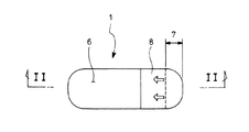
図1〜図4は本発明を実施する形態例を示すもので、図1は本発明を実施する形態例を示す平面図、図2は図1のII−II方向の矢視図、図3は救急絆の施用方法において第二の剥離紙を剥離してシート基材を適用箇所に貼付した状態を示す概念図、図4は救急絆の施用方法を示すフロー図である。 1 to 4 show an embodiment for carrying out the present invention, FIG. 1 is a plan view showing an embodiment for carrying out the present invention, FIG. 2 is a view in the direction of arrows II-II in FIG. the conceptual view showing a state in which sticking a sheet substrate to application site by peeling the second release paper in a method of applying the salvation rapid bond, FIG. 4 is a flow diagram illustrating a method for applying salvation rapid bond.
実施の形態例の救急絆1は、表面に対して裏側に接着面2を配するウレタンフィルム等のシート基材3と、シート基材3の長手方向の一端から接着面2の略中央までを剥離可能に被覆する第一の剥離紙4と、シート基材3の長手方向の他端からシート基材3の残りの接着面2を剥離可能に被覆する第二の剥離紙5と、シート基材3と略同じ形状で形成され且つシート基材3の形状を支持するようシート基材3の表面を剥離可能に被覆する樹脂フィルム等のキャリア6とを備えている。
The first embodiment of the
シート基材3は、ウレタンフィルムの素材で構成され、一般的な救急絆と略同じ大きさで構成されている。また、接着面2には、薬剤を含んで直接傷部に貼付し得るようにしている。ここで、シート基材3の素材は、接着面2により適用箇所に貼付し得るならばウレタンフィルム等に限定されるものではない。
The sheet |
第一の剥離紙4は、中央寄り側部で折り返された把持部4aを形成しており、第二の剥離紙5は、第二の剥離紙4の把持部4aを覆う延在部5aを形成している。
The first release paper 4 forms a grip portion 4 a that is folded back on the side closer to the center, and the
キャリア6の端部6aには、シート基材3に対して予め剥離するよう、溶着されてない非接着帯7が構成されており、非接着帯7は、キャリア6の長手方向の先端からキャリアの長手方向の中央方向へ向かって形成されると共に、キャリア6の長手方向全長に対して8%〜37%の長さ、好ましくは10%〜19%の長さで形成されている。ここで、キャリア6は、シート基材3を支持する硬さを有すると共に、シート基材3に付随して指等の曲率の大きい部分に、ある程度巻き付けうる柔軟性を有し、ポリエチレンテレフタレート(PET)、ポリプロピレン(PP)、ポリエチレン(PE)等の素材で構成されている。また、キャリア6の非接着帯7は、キャリア6の一端部に備えられるのみならず、キャリア6の両端部に備えられても良いし、その他の周囲に配置されても良い。
A
また、キャリア6の端部6aには、キャリア6の他の位置よりも強度を高める補強部8が備えられており、補強部8は、キャリア6よりも突出することがない形状で、キャリア6の表面に溶着される補助シートで構成されると共に、非接着帯7よりも長く構成され且つキャリア6の長手方向全長に対して20%〜50%の長さ、好ましくは28%〜46%の長さで形成されている。ここで、補強部8は、キャリア6を補強するならば、素材は特に限定されるものではないが、キャリア6及びシート基材3と共に、形状を切り揃え得るものが好ましい。また、補強部8には、キャリア6を剥離する方向やその他の表示を記載しても良い。
Further, the
次に、救急絆1の施用方法を図面を参照しつつ説明する。
Next, with reference to the drawings a method of applying the salvation
救急絆1を指等の曲率の大きい適用箇所Sに施用する際には、第二の剥離紙5をシート基材3から剥離し(図4のステップA1)、接着面2に触れないように第一の剥離紙4及びキャリア6を把持し(図4のステップA2)、直接若しくは消毒綿等(図示せず)を介して適用箇所Sにシート基材3を仮貼付し(図4のステップA3)、シート基材3から第一の剥離紙4を剥離し(図3の矢印A方向)、シート基材3を完全に貼付する(図4のステップA4)。この時、キャリア6の端部6aは、適用箇所Sへの貼付によって図3に示す如く非接着帯7を介してシート基材3から浮くことにより、このキャリア6の浮いた端部6a部分を把持して他端側へ引き(図3の矢印B方向)、シート基材3からキャリア6を剥離し(図4のステップA5)、シート基材3の貼付を完了する。
When the
また、救急絆1を曲率の小さい適用箇所や略平面状の提供箇所に施用する際には、同様な手順でシート基材3を貼付する。
Moreover, when applying the
このように本発明を実施する形態例の救急絆1によれば、非接着帯7を備えるので、キャリア6にシート基材3を支持する硬さ(強度)を有し且つキャリア6を配した状態でシート基材3を、指等の曲面の大きい適用箇所Sに巻き付け、シート基材3を適切に貼付することができる。また、非接着帯7及び補強部8によりキャリア6の端部6aがシート基材3から浮き、キャリア6の浮いた端部6a部分を摘み部にするので、キャリア6をシート基材3から容易に剥離することができると共に、摘み部を備える工程や材料を不要にして製造コストを低減することができる。
Thus , according to the first embodiment of the first embodiment of the present invention, since the
また、シート基材3を支持するキャリア6の硬さ(強度)を維持するので、キャリア6によってシート基材3を支持できない状態を無くし、シート基材3の形状を崩したり、シート基材3にシワ、捩れ、ゴワつきを生じたりすることを防止できる。更に、シート基材3を曲げない状態で保持する際には、非接着帯7においてキャリア6がシート基材3に寄り添って位置するので、シート基材3の形状を崩すことを防止できる。
In addition, since the hardness (strength) of the
本発明を実施する形態例において、補強部8を、キャリア6に配置する補助シートで構成すると、補助シートの強度を選択することにより、曲面を有する適用箇所Sに応じてキャリア6の端部6aがシート基材3から好適に浮くので、指等の曲率の大きい適用箇所Sにシート基材3を巻き付けて適切に貼付することができる。また、補強部8を簡易な構成にすると共に既存の設備で製造し得るので、製造コストを低減することができる。更に、補助シートは、シート基材3と略同じ形状で形成されるので、従来の摘み部と異なり、指等の曲率の大きい適用箇所Sにシート基材3を巻き付ける際に、摘み部が邪魔になることを防止できる。更にまた、補助シートに、キャリア6を剥離する方向や摘み部として表示を記載した際には、キャリア6をシート基材3から容易に剥離することができる。
In the embodiment for carrying out the present invention, when the reinforcing
本発明を実施する形態例において、補強部8は、非接着帯7に対応するよう、キャリア6の長手方向の先端からキャリア6の長手方向の中央方向へ向かって形成されると共に、キャリア6の長手方向全長に対して20%〜50%の長さで形成されると、キャリア6を配した状態でシート基材3が、曲面を有する適用箇所Sに貼付された際には、キャリア6の端部6aがシート基材3から浮くので、シート基材3を指等の曲率の大きい適用箇所Sに巻き付けて適切に貼付することができる。ここで、補強部8をキャリア6の長手方向全長に対して20%未満の長さにすると、キャリア6を配した状態でシート基材3が、曲面を有する適用箇所Sに貼付された際に、キャリア6の端部6aがシート基材3から浮くことができず、シート基材3を容易に貼付することができないという問題がある。また、補強部8をキャリア6の長手方向全長に対して50%より大きな長さにすると、キャリア6を配した状態でシート基材3が貼付された際に、補強部8がキャリア6を介してシート基材3に影響を与え、シート基材3に対しシワ、捩れ、ゴワつきを生じて指等の適用箇所Sに好適に巻き付けることができないと共に、製造コストが増加するという問題がある。また、補強部8をキャリア6の長手方向全長に対して28%〜46%にすると、キャリア6の端部6aがシート基材3から適切に浮く作用と、指等の曲率の大きい適用箇所Sに巻き付ける作用との好適なバランスをとることができる。
In the embodiment for carrying out the present invention, the reinforcing
本発明を実施する形態例において、非接着帯7は、キャリア6の長手方向の先端からキャリア6の長手方向の中央方向へ向かって形成されると共に、キャリア6の長手方向全長に対して8%〜37%の長さで形成されると、キャリア6を配した状態でシート基材3が、曲面を有する適用箇所Sに貼付された際には、キャリア6の端部6aがシート基材3から浮くので、シート基材3を指等の曲率の大きい適用箇所Sに巻き付けて適切に貼付することができる。ここで、非接着帯7をキャリア6の長手方向全長に対して8%未満の長さにすると、摘み部を適切に構成することができず、シート基材3を容易に貼付することができないという問題がある。また、非接着帯7をキャリア6の長手方向全長に対して37%より大きい長さにすると、キャリア6がシート基材3を支持する作用が大幅に低下し、シート基材3の形状を崩したり、シート基材3にシワ、捩れ、ゴワつきを生じたりするという問題がある。また、非接着帯7をキャリア6の長手方向全長に対して10%〜19%にすると、指等の曲率の大きい適用箇所Sに巻き付ける作用と、シート基材3を支持する作用との好適なバランスをとることができる。
In the embodiment for carrying out the present invention, the
尚、本発明の救急絆は、上述の形態例にのみ限定されるものではなく、補強部は、補助シートの代わりにキャリアの該当箇所の厚みを増して形成しても良いこと、更に、補強部は、キャリア等に固化剤を塗布して強度を高めても良いこと、その他、本発明の要旨を逸脱しない範囲内において種々変更を加え得ることは勿論である。 In addition, the emergency bond of this invention is not limited only to the above-mentioned example, The reinforcement part may increase the thickness of the applicable location of a carrier instead of an auxiliary sheet, Furthermore, reinforcement Of course, the part may be applied with a solidifying agent on a carrier or the like to increase the strength, and other various modifications can be made without departing from the scope of the present invention.
1 救急絆
2 接着面
3 シート基材
4 第一の剥離紙
5 第二の剥離紙
6 キャリア
7 非接着帯
8 補強部
S 適用箇所
DESCRIPTION OF
Claims (4)
該シート基材の接着面を剥離可能に被覆する剥離紙と、
前記シート基材と略同じ形状及び同じ大きさで形成され且つ前記シート基材の形状を支持するようシート基材の表面を剥離可能に被覆するキャリアと、
該キャリアから外方へ突出することなく、キャリアの端部から表面上に配置されてキャリアの強度を高める補強部とを備え、
前記キャリアの端部には、補強部の下方に位置し且つシート基材の表面から予め剥離された非接着帯を備え、
前記キャリアを配した状態でシート基材が、曲面を有する適用箇所に接着面で貼付された際には、キャリアの端部が非接着帯及び補強部によりシート基材から離間し、キャリアをシート基材から引き剥がすための摘み部となるように構成されたことを特徴とする救急絆。 A sheet base material having an adhesive surface on the back side with respect to the surface ;
A release paper for releasably covering the adhesive surface of the sheet substrate ;
A carrier that is formed in substantially the same shape and the same size as the sheet base and releasably coats the surface of the sheet base to support the shape of the sheet base ;
A reinforcing portion that is arranged on the surface from the end of the carrier without protruding outward from the carrier and increases the strength of the carrier,
At the end of the carrier is provided with a non-adhesive band located below the reinforcing portion and peeled in advance from the surface of the sheet base material,
When the sheet base material is attached to the application part having a curved surface with an adhesive surface in a state where the carrier is arranged , the end portion of the carrier is separated from the sheet base material by the non-adhesive band and the reinforcing portion , and the carrier sheet An emergency bond characterized by being configured to be a knob for peeling off from a base material .
Priority Applications (1)
| Application Number | Priority Date | Filing Date | Title |
|---|---|---|---|
| JP2007317179A JP4824006B2 (en) | 2007-12-07 | 2007-12-07 | First aid |
Applications Claiming Priority (1)
| Application Number | Priority Date | Filing Date | Title |
|---|---|---|---|
| JP2007317179A JP4824006B2 (en) | 2007-12-07 | 2007-12-07 | First aid |
Publications (2)
| Publication Number | Publication Date |
|---|---|
| JP2009136557A JP2009136557A (en) | 2009-06-25 |
| JP4824006B2 true JP4824006B2 (en) | 2011-11-24 |
Family
ID=40867828
Family Applications (1)
| Application Number | Title | Priority Date | Filing Date |
|---|---|---|---|
| JP2007317179A Active JP4824006B2 (en) | 2007-12-07 | 2007-12-07 | First aid |
Country Status (1)
| Country | Link |
|---|---|
| JP (1) | JP4824006B2 (en) |
Families Citing this family (8)
| Publication number | Priority date | Publication date | Assignee | Title |
|---|---|---|---|---|
| JP5456386B2 (en) * | 2009-06-26 | 2014-03-26 | 株式会社共和 | Medical bandage |
| AU2010235989A1 (en) | 2009-10-27 | 2011-05-12 | Nitto Denko Corporation | Medical pressure-sensitive adhesive tape |
| JP5527885B2 (en) * | 2010-02-02 | 2014-06-25 | 日東電工株式会社 | Medical adhesive tape |
| ES2739469T3 (en) * | 2009-12-28 | 2020-01-31 | Teikoku Seiyaku Kk | Preparation of adhesive tape |
| WO2012140875A1 (en) * | 2011-04-12 | 2012-10-18 | マイコール株式会社 | Heat generator |
| WO2017170956A1 (en) * | 2016-03-31 | 2017-10-05 | センジュ ユーエスエー、インコーポレイテッド | Patch material |
| CN111031977A (en) * | 2017-06-23 | 2020-04-17 | 日绊株式会社 | Adhesive skin patch with support liner and method of making the same |
| JP2022120860A (en) * | 2021-02-06 | 2022-08-19 | 久寿 住江 | Adhesive tape with sandwiching part |
Family Cites Families (3)
| Publication number | Priority date | Publication date | Assignee | Title |
|---|---|---|---|---|
| JPH0316144U (en) * | 1989-06-30 | 1991-02-18 | ||
| JP3694696B2 (en) * | 1994-10-03 | 2005-09-14 | タック化成株式会社 | dressing |
| JP4260800B2 (en) * | 2005-12-02 | 2009-04-30 | リバテープ製薬株式会社 | Adhesive plaster and method for producing the same |
-
2007
- 2007-12-07 JP JP2007317179A patent/JP4824006B2/en active Active
Also Published As
| Publication number | Publication date |
|---|---|
| JP2009136557A (en) | 2009-06-25 |
Similar Documents
| Publication | Publication Date | Title |
|---|---|---|
| JP4824006B2 (en) | First aid | |
| JP6262531B2 (en) | Elastic strip | |
| JP5036385B2 (en) | Film dressing | |
| EP2558043B1 (en) | Ostomy device | |
| TW201026290A (en) | Conformable wound dressing | |
| JP2008509712A (en) | Compression belt | |
| KR101461269B1 (en) | Film dressing | |
| JP2012506731A5 (en) | ||
| AU762833B2 (en) | A layered product ready for non-touch application and a method for producing such a product | |
| KR20160110205A (en) | System, method, and device for supporting a body part | |
| US7673788B2 (en) | Package opening device | |
| US20070173752A1 (en) | Integrated package | |
| JP5685547B2 (en) | Equipment that facilitates the application of plastic film to the skin | |
| JP2008531153A (en) | Bandage bond with support aid for application | |
| JP3623124B2 (en) | Biological electrode | |
| JP4260800B2 (en) | Adhesive plaster and method for producing the same | |
| JP4649566B2 (en) | Adhesive material | |
| JP4855890B2 (en) | Medical dressing material and method for producing the same | |
| JP2596722Y2 (en) | Sticking material | |
| JP7257205B2 (en) | Tubular body fixture | |
| JP2007126425A (en) | Transdermal patch | |
| JPH09238975A (en) | Self-adhesive film | |
| JP5951176B2 (en) | Dressing material | |
| JP2007130314A (en) | First-aid adhesive tape | |
| JP2009254905A (en) | Magnetic therapeutic device |
Legal Events
| Date | Code | Title | Description |
|---|---|---|---|
| A977 | Report on retrieval |
Free format text: JAPANESE INTERMEDIATE CODE: A971007 Effective date: 20100604 |
|
| A131 | Notification of reasons for refusal |
Free format text: JAPANESE INTERMEDIATE CODE: A131 Effective date: 20110118 |
|
| A521 | Request for written amendment filed |
Free format text: JAPANESE INTERMEDIATE CODE: A523 Effective date: 20110315 |
|
| TRDD | Decision of grant or rejection written | ||
| A01 | Written decision to grant a patent or to grant a registration (utility model) |
Free format text: JAPANESE INTERMEDIATE CODE: A01 Effective date: 20110817 |
|
| A01 | Written decision to grant a patent or to grant a registration (utility model) |
Free format text: JAPANESE INTERMEDIATE CODE: A01 |
|
| A61 | First payment of annual fees (during grant procedure) |
Free format text: JAPANESE INTERMEDIATE CODE: A61 Effective date: 20110907 |
|
| R150 | Certificate of patent or registration of utility model |
Ref document number: 4824006 Country of ref document: JP Free format text: JAPANESE INTERMEDIATE CODE: R150 Free format text: JAPANESE INTERMEDIATE CODE: R150 |
|
| FPAY | Renewal fee payment (event date is renewal date of database) |
Free format text: PAYMENT UNTIL: 20140916 Year of fee payment: 3 |
|
| R250 | Receipt of annual fees |
Free format text: JAPANESE INTERMEDIATE CODE: R250 |
|
| R250 | Receipt of annual fees |
Free format text: JAPANESE INTERMEDIATE CODE: R250 |
|
| R250 | Receipt of annual fees |
Free format text: JAPANESE INTERMEDIATE CODE: R250 |
|
| R250 | Receipt of annual fees |
Free format text: JAPANESE INTERMEDIATE CODE: R250 |
|
| R250 | Receipt of annual fees |
Free format text: JAPANESE INTERMEDIATE CODE: R250 |
|
| R250 | Receipt of annual fees |
Free format text: JAPANESE INTERMEDIATE CODE: R250 |
|
| R250 | Receipt of annual fees |
Free format text: JAPANESE INTERMEDIATE CODE: R250 |
|
| R250 | Receipt of annual fees |
Free format text: JAPANESE INTERMEDIATE CODE: R250 |
|
| R250 | Receipt of annual fees |
Free format text: JAPANESE INTERMEDIATE CODE: R250 |
|
| R250 | Receipt of annual fees |
Free format text: JAPANESE INTERMEDIATE CODE: R250 |