JP4817990B2 - IMAGING DEVICE, ITS CONTROL METHOD, PROGRAM, AND STORAGE MEDIUM - Google Patents
IMAGING DEVICE, ITS CONTROL METHOD, PROGRAM, AND STORAGE MEDIUM Download PDFInfo
- Publication number
- JP4817990B2 JP4817990B2 JP2006177293A JP2006177293A JP4817990B2 JP 4817990 B2 JP4817990 B2 JP 4817990B2 JP 2006177293 A JP2006177293 A JP 2006177293A JP 2006177293 A JP2006177293 A JP 2006177293A JP 4817990 B2 JP4817990 B2 JP 4817990B2
- Authority
- JP
- Japan
- Prior art keywords
- bit rate
- encoding
- unit
- target
- initial value
- Prior art date
- Legal status (The legal status is an assumption and is not a legal conclusion. Google has not performed a legal analysis and makes no representation as to the accuracy of the status listed.)
- Expired - Fee Related
Links
Images


Classifications
-
- H—ELECTRICITY
- H04—ELECTRIC COMMUNICATION TECHNIQUE
- H04N—PICTORIAL COMMUNICATION, e.g. TELEVISION
- H04N19/00—Methods or arrangements for coding, decoding, compressing or decompressing digital video signals
- H04N19/10—Methods or arrangements for coding, decoding, compressing or decompressing digital video signals using adaptive coding
- H04N19/189—Methods or arrangements for coding, decoding, compressing or decompressing digital video signals using adaptive coding characterised by the adaptation method, adaptation tool or adaptation type used for the adaptive coding
- H04N19/196—Methods or arrangements for coding, decoding, compressing or decompressing digital video signals using adaptive coding characterised by the adaptation method, adaptation tool or adaptation type used for the adaptive coding being specially adapted for the computation of encoding parameters, e.g. by averaging previously computed encoding parameters
- H04N19/198—Methods or arrangements for coding, decoding, compressing or decompressing digital video signals using adaptive coding characterised by the adaptation method, adaptation tool or adaptation type used for the adaptive coding being specially adapted for the computation of encoding parameters, e.g. by averaging previously computed encoding parameters including smoothing of a sequence of encoding parameters, e.g. by averaging, by choice of the maximum, minimum or median value
-
- H—ELECTRICITY
- H04—ELECTRIC COMMUNICATION TECHNIQUE
- H04N—PICTORIAL COMMUNICATION, e.g. TELEVISION
- H04N19/00—Methods or arrangements for coding, decoding, compressing or decompressing digital video signals
- H04N19/10—Methods or arrangements for coding, decoding, compressing or decompressing digital video signals using adaptive coding
- H04N19/189—Methods or arrangements for coding, decoding, compressing or decompressing digital video signals using adaptive coding characterised by the adaptation method, adaptation tool or adaptation type used for the adaptive coding
- H04N19/196—Methods or arrangements for coding, decoding, compressing or decompressing digital video signals using adaptive coding characterised by the adaptation method, adaptation tool or adaptation type used for the adaptive coding being specially adapted for the computation of encoding parameters, e.g. by averaging previously computed encoding parameters
- H04N19/197—Methods or arrangements for coding, decoding, compressing or decompressing digital video signals using adaptive coding characterised by the adaptation method, adaptation tool or adaptation type used for the adaptive coding being specially adapted for the computation of encoding parameters, e.g. by averaging previously computed encoding parameters including determination of the initial value of an encoding parameter
-
- H—ELECTRICITY
- H04—ELECTRIC COMMUNICATION TECHNIQUE
- H04N—PICTORIAL COMMUNICATION, e.g. TELEVISION
- H04N19/00—Methods or arrangements for coding, decoding, compressing or decompressing digital video signals
- H04N19/60—Methods or arrangements for coding, decoding, compressing or decompressing digital video signals using transform coding
- H04N19/61—Methods or arrangements for coding, decoding, compressing or decompressing digital video signals using transform coding in combination with predictive coding
Landscapes
- Engineering & Computer Science (AREA)
- Multimedia (AREA)
- Signal Processing (AREA)
- Computing Systems (AREA)
- Theoretical Computer Science (AREA)
- Studio Devices (AREA)
- Compression Or Coding Systems Of Tv Signals (AREA)
- Television Signal Processing For Recording (AREA)
Description
本発明は、カメラステータス情報を用いて画像符号化装置の符号化効率を向上させる技術に関するものである。 The present invention relates to a technique for improving the encoding efficiency of an image encoding apparatus using camera status information.
画像を高能率符号化するための技術として、MPEG2(Moving Picture Experts Group Phase 2)といった符号化方式が確立されている。各メーカーはこのMPEG2符号化方式を利用して画像を記録可能としたデジタルカメラやデジタルビデオカメラといった撮像装置或いはDVDレコーダーなどを開発し、製品化している。そして、ユーザーはこれらの装置或いはパーソナルコンピュータやDVDプレーヤーなどを用いて簡単に画像を視聴することが可能となっている。 As a technique for performing high-efficiency encoding of an image, an encoding method such as MPEG2 (Moving Picture Experts Group Phase 2) has been established. Manufacturers have developed and commercialized imaging devices such as digital cameras and digital video cameras or DVD recorders that can record images using this MPEG2 encoding method. The user can easily view images using these devices, a personal computer, a DVD player, or the like.
このMPEG2符号化方式の符号化効率を向上させるために様々な検討が行われている。そのうち、撮像装置においては、カメラ部の制御データより得られるカメラステータス情報に応じて、符号化処理の符号量制御で使用される目標符号量等の符号化パラメータを設定することにより符号化効率を向上させる技術が知られている(特許文献1)。 Various studies have been made to improve the encoding efficiency of this MPEG2 encoding system. Among them, in the imaging apparatus, encoding efficiency is improved by setting an encoding parameter such as a target code amount used in code amount control of the encoding process according to camera status information obtained from control data of the camera unit. A technique for improving this is known (Patent Document 1).
ここで、MPEG2符号化方式の符号量制御についてリファレンスソフトエンコーダーであるTM5の例を挙げて説明する。TM5とは、”Test Model Editing Committee: “TestModel 5”, ISO/IEC, JTC/SC29/WG11/n0400 (Apr.1993)に記載されている。 Here, the code amount control of the MPEG2 encoding method will be described with reference to an example of TM5 which is a reference soft encoder. TM5 is described in “Test Model Editing Committee:“ Test Model 5 ”, ISO / IEC, JTC / SC29 / WG11 / n0400 (Apr. 1993).
TM5の符号量制御は以下の3つのステップに分けて考えられる。 The code amount control of TM5 can be considered divided into the following three steps.
(ステップ1)の処理では、GOP内の各ピクチャに対する割り当て符号量を、割り当て対象ピクチャを含めGOP内でまだ符号化されていないピクチャに対して割り当てられる総符号量を基に配分する。この配分処理は、GOP内の符号化ピクチャの順に繰り返される。 In the processing of (Step 1), the allocated code amount for each picture in the GOP is distributed based on the total code amount allocated to the pictures that have not been encoded in the GOP including the allocation target picture. This distribution process is repeated in the order of the coded pictures in the GOP.
ここで、一般的な符号量制御について説明しておく。符号量制御に基づくデータ圧縮においては、2種類の符号化方式がある。1つは、発生符号量をほぼ一定に保つ固定ビットレート(CBR)符号化である。また、もう1つは、符号化ビットレートの平均値を長期的な目標ビットレートに近づけながらも、動画の各フレームにおいては画像の複雑さや動きの激しさに応じて最適な符号量配分を行う可変ビットレート(VBR)符号化である。 Here, general code amount control will be described. There are two types of encoding methods for data compression based on code amount control. One is constant bit rate (CBR) coding that keeps the amount of generated code substantially constant. The other is to distribute the optimum code amount according to the complexity of the image and the intensity of motion in each frame of the moving image, while the average value of the encoding bit rate is brought close to the long-term target bit rate. Variable bit rate (VBR) coding.
VBR符号化の理想的な符号量配分は、符号化すべき動画全体に渡っての発生符号量見積もりと、実際の符号化の2パス構成となるため、従来はソフトウェアでのオフライン処理によって実現されてきた。近年、このVBR符号化をリアルタイムで行うハードウェアが開発され、現在のレコーダーでは画質に有利なリアルタイムVBR符号化が行われることが一般的になってきた。従来からのソフトウェアによる、動画全体に渡っての事前の符号量配分に基づく符号化を2パスエンコードと呼ぶのに対し、レコーダー等で用いられるこれらのリアルタイムのビットレート制御技術は1パスエンコードと呼ばれる。 The ideal code amount distribution of VBR encoding has a two-pass configuration of the generated code amount estimation over the entire moving image to be encoded and the actual encoding, and thus has been conventionally realized by offline processing in software. It was. In recent years, hardware for performing this VBR encoding in real time has been developed, and it has become common for current recorders to perform real-time VBR encoding advantageous for image quality. Encoding based on the prior code amount distribution over the entire moving image by software is called two-pass encoding, whereas these real-time bit rate control techniques used in recorders are called one-pass encoding. .
1パスエンコードによるVBRの符号化ビットレート制御は、動画のフレームごとの複雑さや動きの激しさといった局所的な特性に左右されず、2パスエンコードによる理想に近い符号量配分を実現する。そのために、短期的に目標とする符号化ビットレートで符号化した結果得られた実際の符号化ビットレートを平均し、その平均値を長期的に目標とする符号化ビットレートに合わせるよう、所定の期間をかけて徐々に符号量を制御していくことが一般的である。実際の符号化ビットレートの平均値を長期的に目標とする符号化ビットレートへ漸近させる制御の傾きによって目標とする収束符号化ビットレートへの収束時間が決定する。 VBR encoding bit rate control by one-pass encoding realizes code amount distribution close to ideal by two-pass encoding regardless of local characteristics such as the complexity of each moving image frame and the intensity of motion. For this purpose, the actual encoding bit rate obtained as a result of encoding at the target encoding bit rate in the short term is averaged, and the average value is set to match the target encoding bit rate in the long term. In general, the code amount is gradually controlled over the period. The convergence time to the target convergence coding bit rate is determined by the slope of the control that asymptotically approaches the average value of the actual coding bit rate to the target coding bit rate in the long term.
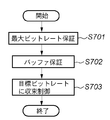
図13は、ビットレート制御の概略フローを示す図である。ステップS701は最大ビットレート保証処理であり、目標収束ビットレートとは別に、最大転送速度など記録上の上限を越えないための制限を現在の量子化スケールに対して行う。ステップS702はバッファ保証であり、MPEG2においてはVBVと呼ばれる仮想バッファがオーバーフロー/アンダーフローを起こさないよう制御することによって、デコード時の破綻が起きないよう、符号化レートを制御するものである。これらステップS701、ステップS702での符号化制御処理は一般的なものであり詳細な説明は省略する。ステップS703は所定の収束時間に基づいて目標収束ビットレートに収束させるための制御処理である。以上のビットレート制御処理により決定された短期目標ビットレートに応じて量子化スケールを変更し発生符号量を制御する。 FIG. 13 is a diagram showing a schematic flow of bit rate control. Step S701 is a maximum bit rate guarantee process. In addition to the target convergence bit rate, a restriction for not exceeding the upper limit on recording such as the maximum transfer speed is applied to the current quantization scale. Step S702 is a buffer guarantee. In MPEG2, the coding rate is controlled so that a failure at the time of decoding does not occur by controlling the virtual buffer called VBV so as not to cause overflow / underflow. The encoding control processing in step S701 and step S702 is general and will not be described in detail. Step S703 is a control process for converging to the target convergence bit rate based on a predetermined convergence time. The generated code amount is controlled by changing the quantization scale in accordance with the short-term target bit rate determined by the above bit rate control processing.
(ステップ2)の処理では、ステップ1で求められた各ピクチャに対する割り当て符号量と、実際の発生符号量を一致させるため、次のようにする。すなわち、I,P,Bの各ピクチャ毎に独立に設定した3種類の仮想バッファの容量を基に、量子化スケールコードを、マクロブロック単位のフィードバック制御で求める。
In the process of (Step 2), in order to match the allocated code amount for each picture obtained in
(ステップ3)の処理では、ステップ2で求められた量子化スケールコードを、視覚的に劣化の目立ち易い平坦部でより細かく量子化し、劣化の比較的目立ち難い絵柄の複雑な部分で粗く量子化する。そのために、16×16画素のマクロブロック毎のアクティビィティと呼ばれる変数によって量子化スケールを変化させ決定する。
In the process of (Step 3), the quantization scale code obtained in
(ステップ3)のアクティビティの算出方法及び量子化スケールの決定方法についてさらに詳しく説明する。 The activity calculation method and quantization scale determination method in (Step 3) will be described in more detail.
絵柄の複雑さを示すアクティビティは、次のように算出される。まず、16×16画素のマクロブロックをフィールド離散コサイン変換モードにおける4つの8×8画素ブロックと、フレーム離散コサイン変換モードにおける4つの8×8画素ブロックとの、合計8つのブロックに分ける。そして、それぞれのブロックにおける原画の輝度信号画素値Pjの分散値var_{sblk}に基づきアクティビティを算出する。各8×8画素ブロックの分散値は式(1)で算出される。Pは8×8画素ブロックの輝度信号画素値Pjの平均画素値である。 The activity indicating the complexity of the pattern is calculated as follows. First, a macro block of 16 × 16 pixels is divided into a total of eight blocks including four 8 × 8 pixel blocks in the field discrete cosine transform mode and four 8 × 8 pixel blocks in the frame discrete cosine transform mode. Then, the activity is calculated based on the variance value var_ {sblk} of the luminance signal pixel value Pj of the original image in each block. The variance value of each 8 × 8 pixel block is calculated by equation (1). P is an average pixel value of the luminance signal pixel values Pj of the 8 × 8 pixel block.

式(1)で求めた合計8つの分散値の中で最小の分散値を見つけ、式(2)に従いアクティビティを算出する。式(2)において分散値の最小値を利用するのは、マクロブロック内の一部だけでも平坦部分のある場合には量子化を細かく行うためである。 The smallest variance value is found among the total of eight variance values obtained by the equation (1), and the activity is calculated according to the equation (2). The reason why the minimum value of the variance value is used in Equation (2) is to perform fine quantization when only a part of the macroblock has a flat part.
act=1+min(var_{sblk}) (2)
式(2)により算出されるアクティビティ値は、輝度信号画素値の分散が大きい複雑な絵柄の画像では大きい値となり、輝度信号画素値の分散が小さい平坦な画像では小さい値となる。更に、式(3)により、アクティビティ値が0.5〜2.0の範囲に収まるように正規化アクティビティN_actを求める。
act = 1 + min (var_ {sblk}) (2)
The activity value calculated by the equation (2) is a large value for an image having a complicated pattern with a large variance of luminance signal pixel values, and a small value for a flat image having a small variance of luminance signal pixel values. Further, the normalized activity N_act is obtained by the equation (3) so that the activity value falls within the range of 0.5 to 2.0.
N_act=(2×act+avg_act)/(act+2×avg_act)
(3)
avg_actは1フレーム前に符号化したアクティビティactの平均を求めた平均アクティビティである。最初の1フレーム目を符号化する際には、TM5方式では平均アクティビティavg_actの初期値としてavg_act=400としている。
N_act = (2 × act + avg_act) / (act + 2 × avg_act)
(3)
avg_act is an average activity obtained by averaging the activities act encoded one frame before. When encoding the first frame, in the TM5 system, avg_act = 400 is set as the initial value of the average activity avg_act.
アクティビティによる視覚特性を考慮した量子化スケールコードMQUANTは、式(3)で算出された正規化アクティビティN_actとステップ2で得られた量子化スケールコードQscを基に次式(4)で与えられる。
The quantization scale code MQUANT considering the visual characteristics of the activity is given by the following expression (4) based on the normalized activity N_act calculated by the expression (3) and the quantization scale code Qsc obtained in
MQUANT=Qsc×N_act (4)
すなわち、アクティビティの値が小さい平坦な画像では量子化スケールコードMQUANTが小さくなるため細かく量子化され、アクティビティの値が大きい複雑な絵柄の画像では量子化スケールコードMQUANTが大きくなるため粗く量子化される。
MQUANT = Qsc × N_act (4)
In other words, a flat image with a small activity value is quantized finely because the quantization scale code MQUANT is small, and a complex picture image with a large activity value is coarsely quantized because the quantization scale code MQUANT is large. .
TM5方式における符号量制御は、以上説明した処理で行われる。
特許文献1のような従来のカメラステータス情報を用いた目標符号量等の符号化パラメータ設定方法は、符号化部が動作し、符号化処理が実行されている期間のカメラステータス情報を用いて符号化時に使用される符号化パラメータを設定していた。そのため、符号化パラメータの初期値を決定するためには、実際に符号化データを記録する符号化部の本動作以前に符号化部を動作させて符号化処理を行い、符号化部の本動作時に使用される符号化パラメータの初期値を決定する必要があった。そのため、余分な符号化部の動作が発生し、消費電力の増加を招くという問題点があった。
A conventional encoding parameter setting method such as a target code amount using camera status information as disclosed in
一方、上記のTM5方式では、式(3)に従い符号化処理開始直後の1フレーム目における正規化アクティビティN_actを演算する際は、avg_act=400の固定値として演算する。そのため、符号化部の本動作以前に符号化部を動作させなくとも符号化パラメータが自動的に一定値に設定されることになり、特許文献1の技術における問題点は解消される。しかしながら、1フレーム目の符号化における符号化パラメータを一定値に設定してしまうと、撮影される画像の状態によっては適切な符号化が行なわれない場合があり、また、消費電力の増加を招く場合もある。
On the other hand, in the above TM5 method, when the normalized activity N_act in the first frame immediately after the start of the encoding process is calculated according to the equation (3), it is calculated as a fixed value of avg_act = 400. Therefore, the encoding parameter is automatically set to a constant value without operating the encoding unit before the main operation of the encoding unit, and the problem in the technique of
従って、本発明は上述した課題に鑑みてなされたものであり、その目的は、1フレーム目の映像の符号化をより適切に行ないつつ、符号化装置の消費電力を低減できるようにすることである。 Accordingly, the present invention has been made in view of the above-described problems, and an object of the present invention is to enable the power consumption of the encoding device to be reduced while more appropriately encoding the video of the first frame. is there.
上述した課題を解決し、目的を達成するために、本発明に係わる撮像装置は、被写体光を光電変換し、映像信号を出力するカメラ部と、前記映像信号を符号化する符号化手段と、前記カメラ部の動作状況に関する情報を取得するカメラ情報取得手段と、前記カメラ情報取得手段により取得された情報に基づいて、前記符号化手段の符号化動作の開始前に、前記符号化手段の最初の符号化動作のための符号化パラメータである初期パラメータを算出する演算手段と、を具備し、前記符号化手段は、前記映像信号に対する符号量が目標符号量になるように符号量制御を行なうとともに、該符号量制御を可変ビットレート方式により行なうものであり、前記初期パラメータは、可変ビットレート方式における短期目標ビットレートであり、前記符号化手段は、前記短期目標ビットレートを目標収束ビットレートより低く設定し、所定の時間をかけて徐々に前記目標収束ビットレートに収束させる第1の符号量制御動作と、前記短期目標ビットレートを目標収束ビットレートより高く設定し、所定の時間をかけて徐々に前記目標収束ビットレートに収束させる第2の符号量制御動作とを行なうことが可能であり、前記演算手段は、前記カメラ情報取得手段により取得された情報に応じて、前記初期パラメータである前記短期目標ビットレートを前記目標収束ビットレートより高い値にするか低い値にするかを演算することを特徴とする。 In order to solve the above-described problems and achieve the object, an imaging apparatus according to the present invention includes a camera unit that photoelectrically converts subject light and outputs a video signal, and an encoding unit that encodes the video signal; Based on the information acquired by the camera information acquisition means, the camera information acquisition means for acquiring information related to the operation status of the camera unit, before the start of the encoding operation of the encoding means, Calculating means for calculating an initial parameter which is an encoding parameter for the encoding operation, and the encoding unit performs code amount control so that the code amount for the video signal becomes a target code amount. In addition, the code amount control is performed by a variable bit rate method, and the initial parameter is a short-term target bit rate in the variable bit rate method, and the code The means sets the short-term target bit rate lower than the target convergence bit rate, and gradually converges to the target convergence bit rate over a predetermined time, and sets the short-term target bit rate as the target. It is possible to perform a second code amount control operation that is set higher than the convergence bit rate and gradually converges to the target convergence bit rate over a predetermined time, and the calculation means includes the camera information acquisition means The short-term target bit rate, which is the initial parameter, is calculated as a value higher or lower than the target convergence bit rate according to the information acquired by (1 ).
また、本発明に係わる撮像装置の制御方法は、被写体光を光電変換し、映像信号を出力するカメラ部と、前記映像信号を符号化する符号化手段とを備える撮像装置を制御する方法であって、前記カメラ部の動作状況に関する情報を取得するカメラ情報取得工程と、前記カメラ情報取得工程において取得された情報に基づいて、前記符号化手段の符号化動作の開始前に、前記符号化手段の最初の符号化動作のための符号化パラメータである初期パラメータを算出する演算工程と、を具備し、前記符号化手段は、前記映像信号に対する符号量が目標符号量になるように符号量制御を行なうとともに、該符号量制御を可変ビットレート方式により行なうものであり、前記初期パラメータは、可変ビットレート方式における短期目標ビットレートであり、前記符号化手段は、前記短期目標ビットレートを目標収束ビットレートより低く設定し、所定の時間をかけて徐々に前記目標収束ビットレートに収束させる第1の符号量制御動作と、前記短期目標ビットレートを目標収束ビットレートより高く設定し、所定の時間をかけて徐々に前記目標収束ビットレートに収束させる第2の符号量制御動作とを行なうことが可能であり、前記演算工程では、前記カメラ情報取得工程により取得された情報に応じて、前記初期パラメータである前記短期目標ビットレートを前記目標収束ビットレートより高い値にするか低い値にするかを演算することを特徴とする。 In addition, a method for controlling an imaging apparatus according to the present invention is a method for controlling an imaging apparatus that includes a camera unit that photoelectrically converts subject light and outputs a video signal, and an encoding unit that encodes the video signal. And a camera information acquisition step for acquiring information related to the operation status of the camera unit, and the encoding means before starting the encoding operation of the encoding means based on the information acquired in the camera information acquisition step. Calculating an initial parameter that is an encoding parameter for the first encoding operation, and the encoding means controls the code amount so that the code amount for the video signal becomes a target code amount. The code amount control is performed by a variable bit rate method, and the initial parameter is a short-term target bit rate in the variable bit rate method. The encoding means sets the short-term target bit rate lower than the target convergence bit rate, and gradually converges to the target convergence bit rate over a predetermined time; and the short-term target It is possible to set the bit rate higher than the target convergence bit rate and perform a second code amount control operation for gradually converging to the target convergence bit rate over a predetermined time. In the calculation step, According to the information acquired by the camera information acquisition step, it is calculated whether the short-term target bit rate, which is the initial parameter, is set to a value higher or lower than the target convergence bit rate .
本発明によれば、1フレーム目の映像の符号化をより適切に行ないつつ、符号化装置の消費電力を低減することが可能となる。 According to the present invention, it is possible to reduce the power consumption of the encoding device while more appropriately encoding the video of the first frame.
以下、本発明の好適な実施形態について、図面を参照して詳細に説明する。 DESCRIPTION OF EMBODIMENTS Hereinafter, preferred embodiments of the present invention will be described in detail with reference to the drawings.
(第1の実施形態)
図1は、本発明の画像符号化装置を内蔵する撮像装置の第1の実施形態の構成を示す図である。
(First embodiment)
FIG. 1 is a diagram showing a configuration of a first embodiment of an imaging apparatus incorporating an image encoding device of the present invention.
図1において、101は撮影を行うカメラ部であり、非圧縮の映像信号及びカメラ部101の動作及び処理を示すカメラステータス情報を出力する。カメラステータス情報については後述する。103はカメラ部101からのカメラステータス情報に応じて符号化開始直後の符号化処理で使用される符号化パラメータの初期値を演算する符号化パラメータ初期値演算部である。102はカメラ部からの非圧縮映像信号を圧縮符号化する符号化部である。104は録画の開始及び停止を指示するための録画スイッチである。105はカメラ部101、符号化部102、符号化パラメータ初期値演算部103を制御する制御部である。符号化部102は符号化処理部106及び符号化パラメータ初期値記憶部107を備えている。
In FIG. 1,
次に、カメラ部101、符号化部102、符号化パラメータ初期値演算部103について詳しく説明する。
Next, the
まず、図2を参照してカメラ部101の構成について説明する。
First, the configuration of the
カメラ部101は、レンズ201と、撮像部202と、A/D変換部203と、カメラ信号処理部204と、カメラ制御部205とを備え、被写体像を撮像し、非圧縮の映像信号と、カメラステータス情報を出力する。
The
続いて、カメラ部101の動作について説明する。
Next, the operation of the
まず、レンズ201は、被写体光を撮像部202に導く。レンズ201は、カメラ制御部205から出力される制御信号に対応してズーム動作や焦点合わせ動作などを行う。撮像部202は、CCDやCMOS等を使って被写体光を電気信号に変換する。A/D変換部203は、撮像部202から出力されるアナログ映像信号をデジタル映像信号に変換する。カメラ信号処理部204は、A/D変換部203より出力されたデジタル映像信号に対して、γ補正、ホワイトバランス調整等の処理を行い、非圧縮映像信号を出力する。カメラ制御部205は、カメラ部101を制御しカメラステータス情報を出力する。このカメラステータス情報とは、カメラ部101を構成する各モジュールの制御データを解析することにより得られる動作及び処理を示す情報である。例えば、レンズ201の制御データからは、ズーム動作状況が得られ、カメラ信号処理部204の制御データからは合焦状態などのカメラステータス情報を得ることができる。以上がカメラ部101に関する説明である。
First, the
次に、図1及び図3を参照して符号化部102の構成について説明する。
Next, the configuration of the
符号化部102は、符号化処理部106及び符号化パラメータ初期値記憶部107を備えて構成される。本実施形態では、符号化処理部106としてMPEG符号化方式を採用した例について説明するが、符号化方式はこれに限ったものではない。
The
図1の符号化処理部106は、図3に示すように、ブロック分割部301、減算器302、離散コサイン変換部303、量子化部304、可変長符号化部305、バッファ部306とを備える。また、逆量子化部307、逆離散コサイン変換部308、加算器309、フレームメモリ310、動き補償部311、動き検出部312、符号量制御部313も備える。そして、図1の符号化パラメータ初期値記憶部107に記憶されている符号化パラメータの初期値が符号化開始直前に符号化処理部106に入力される。そして、その入力された符号化パラメータ初期値に従い、カメラ部101から出力された非圧縮の映像信号をブロックに分割し、ブロック単位に符号化処理を行い符号化データを出力する。
As shown in FIG. 3, the
続いて、符号化処理について図3を参照して説明する。 Next, the encoding process will be described with reference to FIG.
まず、ブロック分割部301は、入力された非圧縮の画像データを例えば16×16画素のブロックに分割する。減算器302は、入力画像データから予測画像データを減算し画像残差データを出力する。予測画像データの生成については後述する。
First, the
離散コサイン変換部303は、減算器302から出力された画像残差データを直交変換処理して変換係数を出力する。そして、量子化部304は上記変換係数を量子化スケールに基づき量子化する。可変長符号化部305には、量子化部304で量子化された変換係数が入力され、可変長符号化部305はこれを可変長符号化して符号化データとする。符号化データは一旦バッファ306に溜められた後、出力される。符号量制御部313は前述のTM5等の方法によりバッファ306に溜められたデータがオーバーフローやアンダーフローを起こさないように量子化スケールを決定し、量子化部304に出力する。
The discrete
一方、量子化部304で量子化された変換係数は予測画像データの生成にも使われる。逆量子化部307は、量子化部304で量子化された変換係数を逆量子化する。さらに、逆離散コサイン変換部308は逆量子化部307で逆量子化された変換係数を逆離散コサイン変換し、復号画像残差データとして出力する。加算器309は、復号画像残差データと予測画像データとを加算し、再構成画像データとして出力する。再構成画像データはフレームメモリ310に記録される。再構成画像データの中で、以降の予測で参照される可能性があるデータは、フレームメモリ310に暫くの期間保存される。
On the other hand, the transform coefficient quantized by the
動き補償部311はフレームメモリ310に記録された再構成画像データを用いて動き検出部312によって検出された動きベクトル情報に基づいて動き補償を行い、予測画像データを生成する。動き検出部312は入力画像データにおける動きベクトルを検出し、検出した動きベクトル情報を動き補償部311と可変長符号化部305へ出力する。
The
図1の符号化パラメータ記憶部107は、後述の符号化パラメータ初期値演算部103により演算された符号化パラメータの初期値を記憶する。一方、符号化処理部106は、符号化処理開始直前に符号化パラメータ記憶部107に記憶されている符号化パラメータの初期値を取り込み、その符号化パラメータ初期値に従い符号化処理を開始する。以上が符号化部102に関する説明である。
The encoding
次に、図1、図4及び図5を参照して符号化パラメータ初期値演算部103について説明する。
Next, the encoding parameter initial
符号化パラメータ初期値演算部103は、カメラ部101よりカメラステータス情報を取り込んで符号化パラメータの初期値を演算する。ここでは具体的な符号化パラメータ初期値演算の例として、前述の式(3)の平均アクティビティavg_actの初期値演算について説明する。
The encoding parameter initial
まず初めに平均アクティビティについて図4を参照して説明する。 First, the average activity will be described with reference to FIG.
平均アクティビティavg_actは、符号化対象フレームの直前フレームにおけるアクティビティactの平均値であり、TM5方式では、その初期値はavg_act=400に設定されている。つまり、TM5方式において式(3)に従い符号化処理開始直後の1フレーム目における正規化アクティビティN_actを演算する際は、avg_act=400の固定値として演算する。本実施形態では、上記のTM5方式を踏襲しながらも、1フレーム目の符号化パラメータに適用するavg_actの値を、カメラ部101のステータスに応じて変化させるようにしている。これにより、1フレーム目の画像の符号化をより適切に行なうことを可能としている。
The average activity avg_act is an average value of the activity act in the frame immediately before the encoding target frame. In the TM5 system, the initial value is set to avg_act = 400. That is, in the TM5 method, when calculating the normalized activity N_act in the first frame immediately after the start of the encoding process according to the equation (3), it is calculated as a fixed value of avg_act = 400. In this embodiment, the value of avg_act applied to the encoding parameter of the first frame is changed according to the status of the
図4は式(3)におけるアクティビティactと正規化アクティビティN_actの関係を平均アクティビティavg_act毎に示した図である。横軸がアクティビティ値を示し、縦軸が正規化アクティビティを示す。例えば、平均アクティビティavg_actの値が200で、アクティビティactの値が600の図4の点A1における正規化アクティビティN_actの値は1.4である。図4より、同じアクティビティ値に対する正規化アクティビティ値(例えば、点A1と点A2)を比較すると、平均化アクティビティの値が小さい(点A1)の方が式(3)で算出される正規化アクティビティの値は大きい値となる。そのため、粗く量子化される傾向にあると言える。逆に、平均化アクティビティの値が大きい(点A2)の方が式(3)で算出される正規化アクティビティの値は小さい値となり、細かく量子化される傾向にあると言える。つまり、画像の複雑さを表すアクティビティ値が同じ場合、平均アクティビティ値が小さいほど粗く量子化が行われる傾向にある。 FIG. 4 is a diagram showing the relationship between the activity act and the normalized activity N_act in the equation (3) for each average activity avg_act. The horizontal axis represents activity values, and the vertical axis represents normalized activities. For example, the value of the normalized activity N_act at point A1 in FIG. 4 where the value of the average activity avg_act is 200 and the value of the activity act is 600 is 1.4. From FIG. 4, when the normalized activity values (for example, point A1 and point A2) with respect to the same activity value are compared, the normalized activity value with the smaller average activity value (point A1) is calculated by equation (3). The value of becomes a large value. Therefore, it can be said that it tends to be roughly quantized. On the contrary, it can be said that the value of the normalized activity calculated by the equation (3) is smaller when the value of the average activity is large (point A2) and tends to be finely quantized. That is, when the activity values representing the complexity of the images are the same, the smaller the average activity value, the more likely the quantization is performed.
次に図5を参照して本実施形態の平均アクティビティの初期値を演算する動作について説明する。図5は、平均アクティビティの初期値演算の一例を示すタイミングチャートである。図5(a)はカメラ部101がアクティブ状態かスリープ状態かを示し、図5(b)は符号化部102がアクティブ状態かスリープ状態かを示す。カメラ部101がアクティブの状態とは、例えば、カメラ部101が動作し、非圧縮映像信号及びカメラステータス情報を出力している状態を示す。また、符号化部102がアクティブの状態とは、例えば、符号化処理部106により符号化処理が実行され符号化データを出力している状態を示す。
Next, the operation for calculating the initial value of the average activity according to this embodiment will be described with reference to FIG. FIG. 5 is a timing chart showing an example of an average activity initial value calculation. 5A shows whether the
カメラ部101又は符号化部102がスリープの状態とは、次のような状態である。すなわち、カメラ部101又は符号化処理部106に電源が供給されていないか、カメラ部101又は符号化処理部106へ入力されるクロックが停止している等の理由によりカメラ部101又は符号化処理部106が動作していない状態である。
The sleep state of the
カメラ部101がスリープ状態になると非圧縮映像信号及びカメラステータス情報を出力しない。符号化部102がスリープ状態になると符号化データを出力しないが、符号化パラメータ初期値記憶部107には符号化パラメータの初期値を記録することは可能である。
When the
撮像装置においては、撮像装置の電源を投入した後は、消費電力を低減するために録画が開始されるまでカメラ部101のみ動作させ、符号化部102を停止する撮像装置が多い。カメラ部101がアクティブかつ符号化部102がスリープの状態、つまり、図5の時刻t0〜t1及び時刻t3〜t4の状態をスタンバイモードと呼ぶ。カメラ部101及び符号化部102の両方がアクティブの状態、つまり、図5の時刻t1〜t3及び時刻t4以降の状態を録画モードと呼ぶ。
In many image pickup apparatuses, after the image pickup apparatus is turned on, only the
図5(c)は録画スイッチ104の押下状態を示した図である。録画スイッチ104とは録画の開始及び終了を指示するスイッチであり、この例では、時刻t1において録画スイッチ104が1回押下されることによりスタンバイモードから録画モードへ変更し、録画を開始している。時刻t3において録画スイッチ104がもう一度押下されることにより、録画モードからスタンバインモードへと変更され録画を終了している。さらに、時刻t4で録画スイッチ104が押下されることによりスタンバイモードから録画モードへ変更し、録画を開始している。
FIG. 5C shows a state where the
図5(d)は符号化パラメータ初期値演算部103にカメラ部101から入力されたカメラステータス情報の一例であるフォーカス情報を示している。フォーカス情報とはカメラ信号処理部204から得られる合焦状態を示す情報である。図5(d)では、焦点が合焦している状態を「ロー」、合焦していない状態を「ハイ」で示している。この例では、時刻t0〜t2では焦点が合焦していない。そのため、時刻t0〜t2の期間においてカメラ部101から符号化部102へと出力される非圧縮映像信号はボケた画像となる。また、時刻t2以降では焦点が合焦している。そのため、時刻t2以降においては、カメラ部101から符号化部102へはピントの合った非圧縮映像信号が出力される。
FIG. 5D shows focus information that is an example of camera status information input from the
符号化パラメータ初期値演算部103は、スタンバイモードから録画モードに切り替わる直前、つまり録画スイッチ104が押下された瞬間の時刻t1におけるカメラステータス情報を取り込む。そして、符号化パラメータの初期値を1度だけ演算し、その符号化パラメータの初期値を符号化パラメータ初期値記憶部107に出力し、記録する。その後、符号化処理部106は符号化パラメータ初期値記憶部107に記憶されている符号化パラメータの初期値に従い符号化処理を開始する。
The encoding parameter initial
図5の例では、時刻t1で撮影者が録画スイッチ104を押下した瞬間のカメラステータス情報である図5(d)のフォーカス情報は非合焦であるため、符号化処理部106に入力される画像はボケた画像である。ボケた画像の場合では、画像再生時に視聴者の注目度が低いため画像に対して与える符号量を少なくし、解像感を低下させたとしても影響は少ない。そこで、このような場合においては粗く量子化を行うように平均アクティビティの値を小さくする(例えば50)。また、時刻t4で撮影者が録画スイッチ104を押下した瞬間のフォーカス情報は合焦であるため、符号化処理部106に入力される画像はピントの合った画像である。ピントの合った画像の場合では、画像再生時に視聴者の注目度が高いため画像に符号量を多く与え、解像感を向上させた方がよい。そこで、このような場合においては細かく量子化を行うように平均アクティビティの値を大きくする(例えば400)。
In the example of FIG. 5, the focus information in FIG. 5D, which is the camera status information at the moment when the photographer presses the
以上のように、符号化パラメータ初期値演算部103は、ボケた画像の場合では平均アクティビティの初期値を小さい値として出力し、ピントの合った画像の場合では平均アクティビティの初期値を大きい値として出力する。このことにより符号化開始直後のボケた画像は粗く量子化し、ピントの合った画像は細かく量子化することができる。
As described above, the encoding parameter initial
また、カメラステータス情報は手ぶれ情報、ズーム情報、パン・チルト情報でもよい。カメラステータス情報が手ぶれ情報の場合では、撮影者が録画スイッチ104を押下した瞬間に手ぶれが発生している場合は、映像が手ぶれにより振動しているため視聴者の注目度は低くなる。そこで、このような場合においては粗く量子化を行うように平均アクティビティの値を小さくする(例えば50)。一方、撮影者が録画スイッチ104を押下した瞬間に手ぶれが発生していない場合は、映像が振動してないため視聴者の注目度は高くなる。そこで、このような場合においては細かく量子化を行うように平均アクティビティの値を大きくする(例えば400)。
The camera status information may be camera shake information, zoom information, and pan / tilt information. In the case where the camera status information is camera shake information, if camera shake occurs at the moment when the photographer presses the
カメラステータス情報がズーム情報又はパン・チルト情報の場合では、撮影者が録画スイッチ104を押下した瞬間にズーム中又はパン・チルト中である場合は、映像の動きが速く視聴者の注目度は低くなる。そこで、このような場合においては粗く量子化を行うように平均アクティビティの値を小さくする(例えば50)。一方、撮影者が録画スイッチ104を押下した瞬間の映像がズーム中又はパン・チルト中でない場合は、視聴者の注目度は高くなる。そこで、このような場合においては細かく量子化を行うように平均アクティビティの値を大きくする(例えば400)。
When the camera status information is zoom information or pan / tilt information, when the photographer is zooming or panning / tilting at the moment the
次に、上述した本実施形態のカメラステータス情報に応じて符号化パラメータの初期値を演算し、その符号化パラメータの初期値に従い符号化を行う処理について図6のフローチャートを参照して説明する。 Next, processing for calculating an initial value of an encoding parameter according to the camera status information of the present embodiment described above and performing encoding according to the initial value of the encoding parameter will be described with reference to the flowchart of FIG.
まず、ステップS601において、撮像装置本体の電源を投入する。撮像装置の電源を投入すると、ステップS602において撮像装置はスタンバイモードになり、カメラ部101がアクティブ状態、符号化部102がスリープ状態となる。
First, in step S601, the imaging apparatus main body is turned on. When the power of the imaging apparatus is turned on, the imaging apparatus is in a standby mode in step S602, the
撮影者は撮像装置付属の図示しないファインダーや液晶モニタ等の表示装置により撮影したい構図の決定等の操作を行う。撮影したい構図が決定したら、ステップS603において撮影者は撮像装置の録画スイッチ104を押下し、録画の開始を指示する。ステップS603において録画スイッチ104が押下された瞬間に、符号化パラメータ初期値演算部103はステップS604においてカメラ部101よりカメラステータス情報を取り込む。そして、ステップS605において、前述の方法によってステップS604においてカメラ部101より取り込んだカメラステータス情報に応じて符号化パラメータの初期値を演算する。そして、ステップS606において演算した初期値を符号化パラメータ記憶部107へ出力し、記録する。
The photographer performs operations such as determination of a composition to be photographed by a display device such as a finder or a liquid crystal monitor (not shown) attached to the imaging device. When the composition to be photographed is determined, in step S603, the photographer presses the
符号化パラメータの初期値が記録されると、ステップS607において録画モードへ移行し、カメラ部101及び符号化部102がアクティブ状態となる。ステップS608において、符号化処理部106はステップS606で符号化パラメータ記憶部107に記録された符号化パラメータの初期値を取り込み、その符号化パラメータ初期値に従い符号化処理を実行しステップS609において符号化データを出力する。
When the initial value of the encoding parameter is recorded, in step S607, the recording mode is entered, and the
なお、録画スイッチ104が押下された直後の1フレーム目の映像データの符号化には、上記の符号化パラメータ初期値が用いられる。しかし、2フレーム目からはその直前のフレームにおける平均アクティビティの情報が得られるので、その情報を元に符号化パラメータが設定される。すなわち、2フレーム目からは映像のパターンに従って、符号化パラメータはリアルタイムに変化する。そして、この符号化処理はステップS610において撮影者により録画スイッチ104が再度押下され、録画が終了するまで実行される。ステップS610において録画を終了する場合は、ステップS611においてスタンバイモードとなり録画が終了する。
Note that the encoding parameter initial value is used for encoding the video data of the first frame immediately after the
(第2の実施形態)
次に、本発明の第2の実施形態について説明する。ただし、第1の実施形態と同じ動作、処理を行うものには、第1の実施形態と同じ符号を付して、その説明を省略する。
(Second Embodiment)
Next, a second embodiment of the present invention will be described. However, the same operations and processes as those in the first embodiment are denoted by the same reference numerals as those in the first embodiment, and description thereof is omitted.
また、本実施形態の撮像装置の外見的構成は図1に示した第1の実施形態の構成と同様であるので説明を省略する。 Further, the appearance configuration of the imaging apparatus of the present embodiment is the same as the configuration of the first embodiment shown in FIG.
本実施形態における、カメラステータス情報に応じて符号化パラメータの初期値を演算し、その符号化パラメータの初期値に従って符号化を行う処理について図7のフローチャートを参照して説明する。 Processing for calculating an initial value of an encoding parameter according to camera status information and performing encoding according to the initial value of the encoding parameter in the present embodiment will be described with reference to the flowchart of FIG.
まず、ステップS701において、撮像装置本体の電源を投入する。撮像装置の電源を投入すると、ステップS702において撮像装置はスタンバイモードになり、カメラ部101がアクティブ状態、符号化部102がスリープ状態となる。
First, in step S701, the imaging apparatus main body is turned on. When the power of the imaging apparatus is turned on, the imaging apparatus is in a standby mode in step S702, the
スタンバイモードの時に、符号化パラメータ初期値演算部103はステップS703においてカメラ部101よりカメラステータス情報を取り込んで、ステップS704において第1の実施形態と同様の処理により符号化パラメータ初期値を演算する。そして、ステップS705においてステップS704で演算した符号化パラメータ初期値を符号化パラメータ初期値記憶部107に記録する。
In the standby mode, the encoding parameter initial
ステップS706において、ステップS702〜ステップS705までの処理を撮影者により録画スイッチ104が押下され、録画を開始するまで行い、符号化パラメータ初期値の演算及び記録を定期的に繰り返す。すなわち、符号化パラメータ初期値記憶部107に記録されている符号化パラメータの初期値を定期的に更新し続ける。
In step S706, the processing from step S702 to step S705 is performed until the
ステップS706において録画が開始されたら、ステップS707において録画モードへ移行する。そして、第1の実施形態の処理と同様に、ステップS708において符号化処理部106はステップS705で符号化パラメータ記憶部107に記録された符号化パラメータの初期値を取り込んで、その符号化パラメータ初期値に従い符号化処理を実行し、ステップS709において符号化データを出力する。そして、この符号化処理はステップS710において撮影者により録画スイッチ104が再度押下され、録画が終了するまで実行される。ステップS710において録画を終了する場合は、ステップS711においてスタンバイモードとなり録画が終了する。
When recording is started in step S706, the process proceeds to the recording mode in step S707. Similar to the processing of the first embodiment, in step S708, the
(第3の実施形態)
次に本発明の第3の実施形態について説明する。
(Third embodiment)
Next, a third embodiment of the present invention will be described.
図8は、本発明の画像符号化装置を内蔵する撮像装置の第3の実施形態の構成を示す図である。以下、第3の実施形態について図8を参照して説明する。ただし、第1及び第2の実施形態と同じ動作、処理を行うものには、第1及び第2の実施形態と同じ符号を付して、その説明を省略する。 FIG. 8 is a diagram showing a configuration of a third embodiment of an imaging apparatus incorporating the image encoding device of the present invention. Hereinafter, a third embodiment will be described with reference to FIG. However, the same operations and processes as those in the first and second embodiments are denoted by the same reference numerals as those in the first and second embodiments, and the description thereof is omitted.
図8において、801はカメラ部から出力されるカメラステータス情報に対してフィルタ処理を行い、フィルタ処理されたカメラステータス情報を出力するフィルタ処理部である。フィルタ処理の例としては、ローパスフィルタ処理やハイパスフィルタ処理があるが、ここではローパスフィルタの例として時間的な平均値を算出する平滑化フィルタについて図9を参照して説明する。
In FIG. 8,
図9(d)は合焦状態を示すフォーカス情報を示す。図9(d)のフォーカス情報の例は、時刻t0〜t1において合焦と非合焦を繰り返していることを示している。フィルタ部801は図9(d)のように変化するフォーカス情報を定期的に取り込んで、平滑化処理を行う。そして、平滑化されたフォーカス情報を符号化パラメータ初期値演算部103に出力する。なお、図9(a)〜(c)は、図5(a)〜(c)と同様の内容を示している。
FIG. 9D shows focus information indicating an in-focus state. The example of focus information in FIG. 9D indicates that focusing and non-focusing are repeated at times t0 to t1. The
次に平滑化フィルタ処理されたカメラステータス情報に応じて符号化パラメータの初期値を定期的に演算し、その符号化パラメータの初期値に従い符号化を行う処理について図10のフローチャートを参照して説明する。 Next, processing for periodically calculating the initial value of the encoding parameter according to the camera status information subjected to the smoothing filter processing and performing encoding according to the initial value of the encoding parameter will be described with reference to the flowchart of FIG. To do.
まず、ステップS1001において、撮像装置本体の電源を投入する。撮像装置の電源を投入すると、ステップS1002において撮像装置はスタンバイモードになり、カメラ部101がアクティブ状態、符号化部102がスリープ状態となる。
First, in step S1001, the imaging apparatus main body is turned on. When the power of the imaging apparatus is turned on, in step S1002, the imaging apparatus is in a standby mode, the
ステップS1003においてフィルタ部801はカメラ部101よりカメラステータス情報を取り込んで、ステップS1004において平滑化フィルタ処理を行う。ステップS1005において符号化パラメータ初期値演算部103はステップS1004においてフィルタ部801より出力された平滑化カメラステータス情報を取り込む。そして、ステップS1006において第1の実施形態と同様の処理により、平滑化されたカメラステータス情報に応じて符号化パラメータ初期値を演算する。さらに、ステップS1007においてステップS1006で演算した符号化パラメータ初期値を符号化パラメータ初期値記憶部107に記録する。
In step S1003, the
ステップS1008において、ステップS1002〜ステップS1007までの処理を撮影者により録画スイッチ104が押下され、録画を開始するまで行い、符号化パラメータ初期値の演算及び記録を定期的に繰り返す。すなわち、符号化パラメータ初期値記憶部107に記録されている符号化パラメータの初期値を定期的に更新し続ける。
In step S1008, the processing from step S1002 to step S1007 is performed until the
ステップS1008において録画が開始されたら、ステップS1009において録画モードへ移行する。そして、第1の実施形態の処理と同様に、ステップS1010において符号化処理部106はステップS1007で符号化パラメータ記憶部107に記録された符号化パラメータの初期値を取り込み、その符号化パラメータ初期値に従い符号化処理を実行し、ステップS1011において符号化データを出力する。
When recording starts in step S1008, the process shifts to the recording mode in step S1009. Similar to the processing of the first embodiment, in step S1010, the
なお、符号化パラメータ初期値演算部103は、定期的に符号化パラメータ初期値の演算を行なわないようにしてもよい。すなわち、第1の実施形態と同様に符号化パラメータの初期値をスタンバイモードから録画モードに移行する際に1度だけ演算し、符号化パラメータ初期値記憶部107に出力してもよい。そして、この符号化処理はステップS1012において撮影者により録画スイッチ104が再度押下され、録画が終了するまで実行される。ステップS1012において録画を終了する場合は、ステップS1013においてスタンバイモードとなり録画が終了する。
Note that the encoding parameter initial
以上説明したように、上記の第1及び第3の実施形態によれば、符号化部が動作していないスタンバイモードから符号化処理を行う録画モードに移行する際に、符号化部を動作させることなくカメラステータス情報に応じて符号化パラメータの初期値を決定する。そのため、従来のような符号化処理の初期値を決定するために、実際に符号化データを記録する符号化部の本動作以前に符号化処理を実行しなければならない場合に比べ、符号化処理を実行しなくとも符号化パラメータの初期値を適切に設定できる。これにより、画像符号化装置の消費電力を低減することができる。 As described above, according to the first and third embodiments, the encoding unit is operated when shifting from the standby mode in which the encoding unit is not operating to the recording mode in which the encoding process is performed. Instead, the initial value of the encoding parameter is determined according to the camera status information. Therefore, in order to determine the initial value of the conventional encoding process, the encoding process is performed compared to the case where the encoding process must be executed before this operation of the encoding unit that actually records the encoded data. The initial value of the encoding parameter can be appropriately set without executing the above. Thereby, the power consumption of an image coding apparatus can be reduced.
(第4の実施形態)
上記の第1乃至第3の実施形態では、符号化における符号量制御方式にTM5方式を用いる場合について説明したが、この第4の実施形態では、符号量制御方式にTM5方式とは異なる方式を用いている。
(Fourth embodiment)
In the first to third embodiments, the case where the TM5 method is used as the code amount control method in the encoding has been described, but in the fourth embodiment, a method different from the TM5 method is used as the code amount control method. Used.
本実施形態では、撮像装置、カメラ部、符号化処理部の外見的構成は、図1乃至図3に示した第1の実施形態の構成と同じであるので、以下の説明では、図1乃至図3を援用して説明を行なう。 In the present embodiment, the appearance configuration of the imaging device, the camera unit, and the encoding processing unit is the same as the configuration of the first embodiment shown in FIGS. 1 to 3, and therefore, in the following description, FIGS. The description will be made with reference to FIG.
なお、図1及び図2については、まったく同一であるので説明を省略し、図3に示す符号化処理部については、各構成要素の内部処理が異なるので、符号化処理部106を含む符号化部102について図1及び図3を参照して説明する。
1 and FIG. 2 are completely the same, and thus the description thereof will be omitted. Since the internal processing of each component is different for the encoding processing unit shown in FIG. 3, encoding including the
符号化部102は符号化処理部106及び符号化パラメータ初期値記憶部107を備えて構成される。本実施形態では、符号化処理部106の符号化方式としてMPEG符号化方式を採用した例について説明するが符号化方式はこれに限ったものではない。
The
図1の符号化処理部106は図3に示すように、ブロック分割部301、減算器302、離散コサイン変換部303、量子化部304、可変長符号化部305、バッファ部306を備える。さらに、逆量子化部307、逆離散コサイン変換部308、加算器309、フレームメモリ310、動き補償部311、動き検出部312、符号量制御部313を備える。そして、符号化処理部106は、図1の符号化パラメータ初期値記憶部107に記憶されている符号化パラメータの初期値を符号化開始直前に取り込む。さらに、その符号化パラメータ初期値に従い、カメラ部101から出力された非圧縮の映像信号をブロックに分割し、ブロック単位に符号化処理を行い符号化データを出力する。
As shown in FIG. 3, the
続いて、符号化処理について図3を参照して説明する。 Next, the encoding process will be described with reference to FIG.
まず、ブロック分割部301は、入力された非圧縮の画像データを例えば16×16画素のブロックに分割する。減算器302は、入力画像データから予測画像データを減算し画像残差データを出力する。
First, the
離散コサイン変換部303は、減算器302から出力された画像残差データを直交変換処理して変換係数を出力する。そして、量子化部304は上記変換係数を量子化スケールに基づき量子化する。この量子化スケールを変化させることによって量子化後の変換係数値は大きく変化し、これによって発生符号量が変化する。
The discrete
可変長符号化部305は、量子化部304で量子化された変換係数を取り込み、これを可変長符号化して符号化データとする。符号化データは、符号化量制御のために一旦バッファ306に溜められた後、出力される。
The variable
符号量制御部313は次のような制御を行なう。バッファ306から得られる、発生符号量、バッファ占有率などの情報を用いて可変ビットレート(VBR)方式に基づき、長期的に目標とする目標収束ビットレートに符号化ビットレートを収束させるための量子化スケール制御を量子化部304に対して行う。
The code
一方、量子化部304で量子化された変換係数は予測画像データの生成にも使われる。逆量子化部307は、量子化部304で量子化された変換係数を逆量子化する。さらに、逆離散コサイン変換部308は逆量子化部307で逆量子化された変換係数を逆離散コサイン変換し、復号画像残差データとして出力する。加算器309は、復号画像残差データと予測画像データとを加算し、再構成画像データとして出力する。再構成画像データはフレームメモリ310に記録される。再構成画像データの中で、以降の予測で参照される可能性があるデータは、フレームメモリ310に暫くの期間保存される。
On the other hand, the transform coefficient quantized by the
動き補償部311はフレームメモリ310に記録された再構成画像データを用いて動き検出部312によって検出された動きベクトル情報に基づいて動き補償を行い、予測画像データを生成する。動き検出部312は入力画像データにおける動きベクトルを検出し、検出した動きベクトル情報を動き補償部311と可変長符号化部305へ出力する。
The
図1の符号化パラメータ記憶部107は、後述の符号化パラメータ初期値演算部103により演算された符号化パラメータの初期値を記憶する。一方、符号量制御部313は符号化処理開始直前に符号化パラメータ記憶部107に記憶されている符号化パラメータの初期値を取り込み、その符号化パラメータ初期値に従い符号化処理を開始する。以上が符号化部102に関する説明である。
The encoding
次に、図1、図5及び図11を参照して符号化パラメータ初期値演算部103について説明する。
Next, the encoding parameter initial
図1の符号化パラメータ初期値演算部103は、カメラ部101よりカメラステータス情報を取り込んで符号化パラメータの初期値を演算する。ここでは具体的な符号化パラメータ初期値演算の例として、可変ビットレート(VBR)方式による符号量制御における短期目標ビットレートの初期値について説明する。
The encoding parameter initial
まず初めに可変ビットレート(VBR)方式による符号量制御の符号化ビットレートについて図11を参照して説明する。 First, an encoding bit rate for code amount control by the variable bit rate (VBR) method will be described with reference to FIG.
図11(a)及び図11(b)は、符号化ビットレート制御の様子を示す図である。L401及びL402は単位時間あたりの符号化ビットレート変化を示し、収束時間Tをかけて緩やかに目標収束ビットレートBRに収束している。 FIG. 11A and FIG. 11B are diagrams showing how the encoding bit rate is controlled. L401 and L402 indicate changes in the encoding bit rate per unit time, and gradually converge to the target convergence bit rate BR over the convergence time T.
前述のように可変ビットレート(VBR)方式による符号量制御は、例えば、ピクチャ単位など短期的に目標とする符号化ビットレートを設定する。そして、符号化した結果得られた実際の符号化ビットレートを平均し、その平均値を長期的に目標とする目標収束ビットレートに近づけながらも、動画の各フレームにおいては画像の複雑さや動きの激しさに応じて最適な符号量配分を行う方式である。 As described above, the code amount control by the variable bit rate (VBR) method sets a target encoding bit rate in the short term, for example, in units of pictures. Then, the actual encoding bit rate obtained as a result of encoding is averaged, and the average value approaches the target convergence bit rate that is the target in the long term, while the complexity and motion of the image are reduced in each frame of the moving image. This is a method of performing optimal code amount distribution according to the severity.
符号化した結果得られた実際の符号化ビットレートの平均値を目標収束ビットレートへ収束させる収束特性としては、2種類ある。1つは、図11(a)のL401のように短期目標ビットレートの初期値を目標収束ビットレートよりも高いビットレートに設定し、所定の期間をかけて徐々に目標収束ビットレートに合わせるような収束特性である。もう一つは、図11(b)のL402のように短期目標ビットレートの初期値を目標収束ビットレートよりも低いビットレートに設定し、所定の期間をかけて徐々に目標収束ビットレートに合わせるような収束特性である。 There are two types of convergence characteristics that converge the average value of the actual encoding bit rates obtained as a result of encoding to the target convergence bit rate. One is to set the initial value of the short-term target bit rate to a bit rate higher than the target convergence bit rate as indicated by L401 in FIG. 11A, and gradually match the target convergence bit rate over a predetermined period. Convergence characteristics. The other is to set the initial value of the short-term target bit rate to a bit rate lower than the target convergence bit rate as indicated by L402 in FIG. 11B, and gradually match the target convergence bit rate over a predetermined period. Such convergence characteristics.
図11(a)のL401に示すように短期目標ビットレートの初期値を目標収束ビットレートよりも高いビットレートに設定すると、符号化開始直後のピクチャにおいて割り当てる符号量が多くなるため画質の良好な画像が得られる。しかし、バッファの占有量が多いために突然複雑な絵柄の画像や動きの激しい画像が入力された時にその複雑な絵柄の画像や動きの激しい画像に対して十分な符号量が与えられず画質が劣化してしまう可能性がある。 If the initial value of the short-term target bit rate is set to a bit rate higher than the target convergence bit rate as indicated by L401 in FIG. 11 (a), the amount of code to be allocated in the picture immediately after the start of encoding is increased, resulting in good image quality. An image is obtained. However, because the buffer occupies a large amount, when an image with a complex picture or a picture with a lot of motion is suddenly input, a sufficient code amount cannot be given to the picture with a complex picture or a picture with a lot of movement, resulting in an image quality. There is a possibility of deterioration.
一方、図11(b)のL402に示すように短期目標ビットレートの初期値を目標収束ビットレートよりも低いビットレートに設定すると、符号化開始直後のピクチャにおいて割り当てる符号量が少なくなるため画質の良好な画像が得られ難い。しかし、バッファの占有量が少ないため突然複雑な絵柄の画像や動きの激しい画像が入力された時にその複雑な絵柄の画像や動きの激しい画像に対して十分な符号量を与えることができる。本実施形態ではこのような収束特性を後述のようにスタンバイモード時のカメラステータス情報に応じて変更する。 On the other hand, when the initial value of the short-term target bit rate is set to a bit rate lower than the target convergence bit rate, as shown by L402 in FIG. It is difficult to obtain a good image. However, since the buffer occupancy is small, it is possible to give a sufficient code amount to an image with a complex picture or an image with a lot of movement when an image with a complicated picture or a picture with a lot of movement is suddenly input. In this embodiment, such a convergence characteristic is changed according to the camera status information in the standby mode as described later.
次に図5を参照して本実施形態の可変ビットレート(VBR)方式による符号量制御における符号化ビットレートの収束特性を変更する動作について説明する。 Next, an operation for changing the convergence characteristic of the encoding bit rate in the code amount control by the variable bit rate (VBR) system of the present embodiment will be described with reference to FIG.
まず、可変ビットレート(VBR)方式による符号量制御における短期目標ビットレートの初期値演算の一例を示すタイミングチャートについて説明する。なお、このタイミングチャートは第1の実施形態における図5と同一であるので、図5を援用して説明する。 First, a timing chart showing an example of an initial value calculation of a short-term target bit rate in code amount control by the variable bit rate (VBR) method will be described. Since this timing chart is the same as FIG. 5 in the first embodiment, description will be made with reference to FIG.
図5(a)はカメラ部101がアクティブ状態かスリープ状態かを示し、図5(b)は符号化部102がアクティブ状態かスリープ状態かを示す。カメラ部101がアクティブの状態とは、例えば、カメラ部101が動作し、非圧縮映像信号及びカメラステータス情報を出力している状態を示す。また、符号化部102がアクティブの状態とは、例えば、符号化処理部106により符号化処理が実行され符号化データを出力している状態を示す。
5A shows whether the
カメラ部101又は符号化部102がスリープの状態とは、次のような状態である。すなわち、カメラ部101又は符号化処理部106に電源が供給されていないか、カメラ部101又は符号化処理部106へ入力されるクロックが停止している等の理由によりカメラ部101又は符号化処理部106が動作していない状態である。
The sleep state of the
カメラ部101がスリープ状態になると非圧縮映像信号及びカメラステータス情報を出力しない。符号化部102がスリープ状態になると符号化データを出力しないが、符号化パラメータ初期値記憶部107には符号化パラメータの初期値を記録することは可能である。
When the
撮像装置においては、撮像装置の電源を投入した後は、消費電力を低減するために録画が開始されるまでカメラ部のみ動作させ、符号化部を停止する撮像装置が多い。カメラ部がアクティブかつ符号化部がスリープの状態、つまり、図5の時刻t0〜t1及び時刻t3〜t4の状態をスタンバイモードと呼ぶ。カメラ部及び符号化部の両方がアクティブの状態、つまり、図5の時刻t1〜t3及び時刻t4以降の状態を録画モードと呼ぶ。 In many image pickup apparatuses, after the image pickup apparatus is turned on, only the camera unit is operated and the encoding unit is stopped until recording is started in order to reduce power consumption. A state in which the camera unit is active and the encoding unit is in a sleep state, that is, a state at time t0 to t1 and time t3 to t4 in FIG. 5 is referred to as a standby mode. A state where both the camera unit and the encoding unit are active, that is, a state after time t1 to t3 and time t4 in FIG. 5 is referred to as a recording mode.
図5(c)は録画スイッチ104の押下状態を示した図である。録画スイッチ104とは録画の開始及び終了を指示するスイッチであり、この例では、時刻t1において録画スイッチ104が1回押下されることによりスタンバイモードから録画モードへ変更し、録画を開始している。時刻t3において録画スイッチ104がもう一度押下されることにより録画モードからスタンバインモードへと変更され録画を終了している。さらに、時刻t4で録画スイッチ104が押下されることによりスタンバイモードから録画モードへ変更し、録画を開始している。
FIG. 5C shows a state where the
図5(d)は符号化パラメータ初期値演算部103がカメラ部101より取り込んだカメラステータス情報の一例であるフォーカス情報を示している。フォーカス情報とはカメラ信号処理部204から得られる合焦状態を示す情報である。図5(d)では、焦点が合焦している状態を「ロー」、合焦していない状態を「ハイ」で示している。この例では、時刻t0〜t2では焦点が合焦していない。そのため、時刻t0〜t2の期間においてカメラ部101から符号化部102へと出力される非圧縮映像信号はボケた画像となる。また、時刻t2以降では焦点が合焦している。そのため、時刻t2以降においては、カメラ部101から符号化部102へはピントの合った非圧縮映像信号が出力される。
FIG. 5D shows focus information that is an example of camera status information captured by the encoding parameter initial
符号化パラメータ初期値演算部103は、スタンバイモードから録画モードに切り替わる直前、つまり録画スイッチ104が押下された瞬間の時刻t1におけるカメラステータス情報を取り込む。そして、符号化パラメータの初期値を少なくとも1回演算し、その符号化パラメータの初期値を符号化パラメータ初期値記憶部107に出力し、記録する。その後、符号量制御部313は符号化パラメータ初期値記憶部107に記憶されている符号化パラメータの初期値に従い符号量制御を行う。
The encoding parameter initial
図5の例では、時刻t1で撮影者が録画スイッチ104を押下した瞬間のカメラステータス情報である図5(d)のフォーカス情報は非合焦であるため、符号化処理部106に入力される画像はボケた画像である。ボケた画像の場合では、画像再生時に視聴者の注目度が低いため画像に対して与える符号量を少なくし、解像感を低下させたとしても画質の劣化は目立たない。そこで、このような場合においては短期目標ビットレートの初期値を目標収束ビットレートよりも低いビットレートに設定する。また、時刻t4で撮影者が録画スイッチ104を押下した瞬間のフォーカス情報は合焦であるため、符号化処理部106に入力される画像はピントの合った画像である。ピントの合った画像の場合では、画像再生時に視聴者の注目度が高いため画像に符号量を多く与え、解像感を向上させた方がよい。そこで、このような場合においては短期目標ビットレートの初期値を目標収束ビットレートよりも高いビットレートに設定する。
In the example of FIG. 5, the focus information in FIG. 5D, which is the camera status information at the moment when the photographer presses the
以上のように、ボケた画像の場合では、短期目標ビットレートの初期値は目標収束ビットレートよりも低いビットレートに設定され、符号化ビットレートは例えば図11(b)のL402ように収束するよう制御される。一方、ピントの合った画像の場合では短期目標ビットレートの初期値は目標収束ビットレートよりも高いビットレートに設定され、符号化ビットレートは例えば図11(a)のL401のように収束するよう制御される。 As described above, in the case of a blurred image, the initial value of the short-term target bit rate is set to a bit rate lower than the target convergence bit rate, and the encoding bit rate converges, for example, as L402 in FIG. It is controlled as follows. On the other hand, in the case of an in-focus image, the initial value of the short-term target bit rate is set to a bit rate higher than the target convergence bit rate, and the encoding bit rate converges, for example, as L401 in FIG. Be controlled.
このことにより、符号化開始直後の画像が注目度の低いボケた画像の場合は短期目標ビットレートが低く設定され、複雑な絵柄の画像や動きの激しい画像が突然入力された場合でも十分な符号量を与えることができる。また、符号化開始直後の画像が注目度の高いピントの合った画像の場合は短期目標ビットレートが高く設定され、注目度の高い画像に対して十分な符号量を与えることができる。 As a result, if the image immediately after the start of encoding is a blurred image with a low degree of attention, the short-term target bit rate is set low, and even if a complex pattern image or an image with intense motion is suddenly input, sufficient encoding is possible. Can give the amount. In addition, when the image immediately after the start of encoding is a focused image with a high degree of attention, the short-term target bit rate is set high, and a sufficient code amount can be given to an image with a high degree of attention.
尚、カメラステータス情報は、手ぶれ情報、ズーム情報又はパン・チルト情報でもよい。カメラステータス情報が手ぶれ情報の場合では、撮影者が録画スイッチ104を押下した瞬間に手ぶれが発生している場合は、映像が手ぶれにより振動しているため視聴者の注目度は低くなる。そこで、このような場合においては短期目標ビットレートの初期値は目標収束ビットレートよりも低いビットレートに設定され、符号化ビットレートは例えば図11(b)のL402ように収束するよう制御される。
The camera status information may be camera shake information, zoom information, or pan / tilt information. In the case where the camera status information is camera shake information, if camera shake occurs at the moment when the photographer presses the
撮影者が録画スイッチ104を押下した瞬間に手ぶれが発生していない場合は、映像が振動してないため視聴者の注目度は高くなる。そこで、このような場合においては短期目標ビットレートの初期値は目標収束ビットレートよりも高いビットレートに設定され、符号化ビットレートは例えば図11(a)のL401のように収束するよう制御される。
If no camera shake occurs at the moment when the photographer presses the
カメラステータス情報がズーム情報又はパン・チルト情報の場合では、撮影者が録画スイッチ104を押下した瞬間にズーム中又はパン・チルト中である場合は、映像の動きが速く視聴者の注目度は低くなる。そこで、このような場合においては短期目標ビットレートの初期値は目標収束ビットレートよりも低いビットレートに設定され、符号化ビットレートは例えば図11(b)のL402のように収束するよう制御される。撮影者が録画スイッチ104を押下した瞬間の映像がズーム中又はパン・チルト中でない場合は、視聴者の注目度は高くなる。そこで、このような場合においては短期目標ビットレートの初期値は目標収束ビットレートよりも高いビットレートに設定され、符号化ビットレートは例えば図11(a)のL401のように収束するよう制御される。
When the camera status information is zoom information or pan / tilt information, when the photographer is zooming or panning / tilting at the moment the
次に、上述した本実施形態のカメラステータス情報に応じて短期目標ビットレートの初期値を演算し、その短期目標ビットレートの初期値に従い符号量制御を行う処理について図12のフローチャートを参照して説明する。 Next, a process for calculating the initial value of the short-term target bit rate according to the camera status information of the present embodiment described above and performing the code amount control according to the initial value of the short-term target bit rate will be described with reference to the flowchart of FIG. explain.
まず、ステップS1201において、撮像装置本体の電源を投入する。撮像装置の電源を投入するとステップS1202において撮像装置はスタンバイモードになり、カメラ部101がアクティブ状態、符号化部102がスリープ状態となる。
First, in step S1201, the imaging apparatus main body is turned on. When the power of the imaging apparatus is turned on, the imaging apparatus enters a standby mode in step S1202, the
撮影者は撮像装置付属の図示しないビューファインダーや液晶モニタ等の表示装置により撮影したい構図の決定等の操作を行う。撮影したい構図が決定したらステップS1203において撮影者は撮像装置の録画スイッチ104を押下し録画の開始を指示する。
The photographer performs operations such as determination of a composition to be photographed by a display device such as a viewfinder (not shown) attached to the imaging device or a liquid crystal monitor. When the composition to be photographed is determined, in step S1203, the photographer presses the
ステップS1203において録画の開始が指示されたら、符号化パラメータ初期値演算部103はステップS1204においてカメラ部101よりカメラステータス情報を取り込む。そして、ステップS1205において前述の方法によってステップS1204においてカメラ部101より取り込んだカメラステータス情報に応じて短期目標ビットレートの初期値を演算する。さらに、ステップS1206において演算した初期値を符号化パラメータ記憶部107へ出力し記録する。
When the start of recording is instructed in step S1203, the encoding parameter initial
短期目標ビットレートの初期値が記録されるとステップS1207において録画モードへ移行し、カメラ部101及び符号化部102がアクティブ状態となる。ステップS1208において符号化処理部106が符号化処理を実行する。その際に符号量制御部313はステップS1206で符号化パラメータ記憶部107に記録された短期目標ビットレートの初期値を取り込み、その短期目標ビットレートの初期値に従い前述の方法により符号量を制御する。
When the initial value of the short-term target bit rate is recorded, the process proceeds to the recording mode in step S1207, and the
そして、ステップS1209において符号化データを出力する。この符号化処理はステップS1210において撮影者により録画スイッチ104が再度押下され、録画が終了するまで実行される。ステップS1210において録画を終了する場合は、ステップS1211においてスタンバイモードとなり録画が終了する。
In step S1209, the encoded data is output. This encoding process is executed until the
上記の第4の実施形態によれば、符号化部が動作していないスタンバイモードから符号化処理を行う録画モードに移行する際に、カメラステータス情報に応じて演算された短期目標ビットレートを符号量制御部が取り込む。これにより、その短期目標ビットレートを短期目標ビットレートの初期値として符号化処理を実行することができる。そのため、符号化パラメータの初期値を決定するためには前もって符号化処理を実行しなければならない従来例に比べ、符号化処理を実行しなくとも符号化パラメータの初期値を適切に設定でき、消費電力の低減及び符号化効率の向上を図ることができる。 According to the fourth embodiment, the short-term target bit rate calculated according to the camera status information is encoded when the recording unit performs the encoding process from the standby mode in which the encoding unit is not operating. The amount control unit takes in. As a result, the encoding process can be executed using the short-term target bit rate as the initial value of the short-term target bit rate. Therefore, compared to the conventional example in which the encoding process must be executed in advance to determine the initial value of the encoding parameter, the initial value of the encoding parameter can be appropriately set without performing the encoding process, and the consumption It is possible to reduce power and improve encoding efficiency.
(第5の実施形態)
図14は、本発明の画像符号化装置を内蔵する撮像装置の第5の実施形態の構成を示す図である。なお、図14においては、第1の実施形態を示す図1と同一機能部分には同一符号を付している。
(Fifth embodiment)
FIG. 14 is a diagram showing a configuration of a fifth embodiment of an imaging device incorporating the image encoding device of the present invention. In FIG. 14, the same functional parts as those in FIG. 1 showing the first embodiment are denoted by the same reference numerals.
図14において、101は撮影を行うカメラ部であり、非圧縮の映像信号及びカメラ部101の動作及び処理を示すカメラステータス情報を出力する。カメラステータス情報については第1の実施形態で説明したとおりである。102はカメラ部からの非圧縮映像信号を圧縮符号化する符号化部である。108はカメラ部からのカメラステータス情報に応じて符号化開始直後の符号化処理で使用される符号化パラメータの初期値を演算する第1符号化パラメータ初期値演算部である。109は第1符号化パラメータ初期値演算部108が演算した第1の符号化パラメータの初期値に応じて第2の符号化パラメータの初期値を演算する第2符号化パラメータ初期値演算部である。104は録画の開始及び停止を指示するための録画スイッチである。105はカメラ部101、符号化部102、第1符号化パラメータ初期値演算部108、第2符号化パラメータ初期値演算部109、録画スイッチ104を制御する制御部である。符号化部102は符号化処理部106及び符号化パラメータ初期値記憶部107から構成される。
In FIG. 14,
なお、カメラ部101、符号化部102については、その構成及び動作は、第1の実施形態で図1乃至図3を参照して説明した内容と同様であるので、説明を省略する。
Note that the configuration and operation of the
次に、図5、図11、及び図14を参照して第1符号化パラメータ初期値演算部108について説明する。
Next, the first encoding parameter initial
図14の第1符号化パラメータ初期値演算部108はカメラ部101よりカメラステータス情報が入力されて符号化パラメータの初期値を演算する。ここでは具体的な符号化パラメータ初期値演算の例として、可変ビットレート(VBR)方式による符号量制御における短期目標ビットレートの初期値について説明する。
The first encoding parameter initial
まず始めに、可変ビットレート(VBR)方式による符号量制御の符号化ビットレートについて図11を参照して説明する。 First, the encoding bit rate of the code amount control by the variable bit rate (VBR) method will be described with reference to FIG.
図11(a)及び図11(b)は符号化ビットレート制御の様子を示す図である。L401及びL402は単位時間あたりの符号化ビットレート変化を示し、収束時間Tをかけて緩やかに目標収束ビットレートBRに収束している。 FIG. 11A and FIG. 11B are diagrams showing how the encoding bit rate is controlled. L401 and L402 indicate changes in the encoding bit rate per unit time, and gradually converge to the target convergence bit rate BR over the convergence time T.
前述のように可変ビットレート(VBR)方式による符号量制御は、例えば、ピクチャ単位など短期的に目標とする符号化ビットレートを設定する。そして、符号化した結果得られた実際の符号化ビットレートを平均し、その平均値を長期的に目標とする目標収束ビットレートに近づけながらも、動画の各フレームにおいては画像の複雑さや動きの激しさに応じて最適な符号量配分を行う。 As described above, the code amount control by the variable bit rate (VBR) method sets a target encoding bit rate in the short term, for example, in units of pictures. Then, the actual encoding bit rate obtained as a result of encoding is averaged, and the average value approaches the target convergence bit rate that is the target in the long term, while the complexity and motion of the image are reduced in each frame of the moving image. The optimal code amount distribution is performed according to the severity.
符号化した結果得られた実際の符号化ビットレートの平均値を目標収束ビットレートへ収束させる収束特性としては、次の2つのものがある。 Convergence characteristics for converging the average value of the actual encoding bit rates obtained as a result of encoding to the target convergence bit rate include the following two.
1つは、図11(a)のL401のように短期目標ビットレートの初期値を目標収束ビットレートよりも高いビットレートに設定し、所定の期間をかけて徐々に目標収束ビットレートに合わせるものである。また、もう1つは、図11(b)のL402のように短期目標ビットレートの初期値を目標収束ビットレートよりも低いビットレートに設定し、所定の期間をかけて徐々に目標収束ビットレートに合わせるものである。 One is to set the initial value of the short-term target bit rate to a bit rate higher than the target convergence bit rate as indicated by L401 in FIG. 11 (a), and gradually match the target convergence bit rate over a predetermined period. It is. The other is to set the initial value of the short-term target bit rate to a bit rate lower than the target convergence bit rate as indicated by L402 in FIG. 11 (b), and gradually increase the target convergence bit rate over a predetermined period. To match.
図11(a)のL401に示すように短期目標ビットレートの初期値を目標収束ビットレートよりも高いビットレートに設定すると、符号化開始直後のピクチャにおいて割り当てる符号量が多くなるため画質の良好な画像が得られる。しかし、バッファの占有量が多いために突然複雑な絵柄の画像や動きの激しい画像が入力された時にその複雑な絵柄の画像や動きの激しい画像に対して十分な符号量が与えられず画質が劣化してしまう可能性がある。 If the initial value of the short-term target bit rate is set to a bit rate higher than the target convergence bit rate as indicated by L401 in FIG. 11 (a), the amount of code to be allocated in the picture immediately after the start of encoding is increased, resulting in good image quality. An image is obtained. However, because the buffer occupies a large amount, when an image with a complex picture or a picture with a lot of motion is suddenly input, a sufficient code amount cannot be given to the picture with a complex picture or a picture with a lot of movement, resulting in an image quality. There is a possibility of deterioration.
一方、図11(b)のL402に示すように短期目標ビットレートの初期値を目標収束ビットレートよりも低いビットレートに設定すると、符号化開始直後のピクチャにおいて割り当てる符号量が少なくなるため画質の良好な画像が得られ難い。しかし、バッファの占有量が少ないため突然複雑な絵柄の画像や動きの激しい画像が入力された時に、その複雑な絵柄の画像や動きの激しい画像に対して十分な符号量を与えることができる。 On the other hand, when the initial value of the short-term target bit rate is set to a bit rate lower than the target convergence bit rate, as shown by L402 in FIG. It is difficult to obtain a good image. However, since the buffer occupancy is small, it is possible to give a sufficient amount of code to an image with a complex picture or an image with a lot of movement when a picture with a complex picture or a picture with a lot of movement is suddenly input.
次に図5を参照して本実施形態の可変ビットレート(VBR)方式による符号量制御の符号化ビットレートの収束特性を変更する動作について説明する。 Next, an operation for changing the convergence characteristic of the coding bit rate of the code amount control by the variable bit rate (VBR) method of the present embodiment will be described with reference to FIG.
図5は可変ビットレート(VBR)方式による符号量制御における短期目標ビットレートの初期値演算の一例を示すタイミングチャートである。図5(a)はカメラ部101がアクティブ状態かスリープ状態かを示し、図5(b)は符号化部102がアクティブ状態かスリープ状態かを示す。
FIG. 5 is a timing chart showing an example of the initial value calculation of the short-term target bit rate in the code amount control by the variable bit rate (VBR) method. 5A shows whether the
カメラ部101がアクティブの状態とは、例えば、カメラ部101が動作し、非圧縮映像信号及びカメラステータス情報を出力している状態を示す。また、符号化部102がアクティブの状態とは、例えば、符号化処理部106により符号化処理が実行され符号化データを出力している状態を示す。カメラ部101又は符号化部102がスリープの状態とは、例えば、次のような状態である。即ち、カメラ部101又は符号化処理部106に電源が供給されていないか、カメラ部101又は符号化処理部106へ入力されるクロックが停止している等の理由によりカメラ部101又は符号化処理部106が動作していない状態である。
The state in which the
カメラ部101がスリープ状態になると非圧縮映像信号及びカメラステータス情報を出力しない。符号化部102がスリープ状態になると符号化データを出力しないが、符号化パラメータ初期値記憶部107には符号化パラメータの初期値を記録することは可能である。
When the
撮像装置においては、撮像装置の電源を投入した後は、消費電力を低減するために録画が開始されるまでカメラ部のみ動作させ、符号化部を停止する撮像装置が多い。 In many image pickup apparatuses, after the image pickup apparatus is turned on, only the camera unit is operated and the encoding unit is stopped until recording is started in order to reduce power consumption.
カメラ部101がアクティブかつ符号化部102がスリープの状態、つまり、図5の時刻t0〜t1及び時刻t3〜t4の状態をスタンバイモードと呼ぶ。
A state in which the
カメラ部101及び符号化部102の両方がアクティブの状態、つまり、図5の時刻t1〜t3及び時刻t4以降の状態を録画モードと呼ぶ。
A state where both the
図5(c)は録画スイッチ104の押下状態を示したものである。録画スイッチ104とは録画の開始及び終了を指示するスイッチであり、この例では、時刻t1において録画スイッチが1回押下されることによりスタンバイモードから録画モードへ変更し、録画を開始している。時刻t3において録画スイッチ104がもう一度押下されることにより録画モードからスタンバインモードへと変更され録画を終了している。さらに、時刻t4で録画スイッチが押下されることによりスタンバイモードから録画モードへ変更し、録画を開始している。
FIG. 5C shows the pressing state of the
図5(d)は第1符号化パラメータ初期値演算部108にカメラ部101より入力されたカメラステータス情報の一例であるフォーカス情報を示している。フォーカス情報とはカメラ信号処理部204から得られる合焦状態を示す情報である。図5(d)では、焦点が合焦している状態を「ロー」、合焦していない状態を「ハイ」で示している。この例では、時刻t0〜t2では焦点が合焦していない。そのため、時刻t0〜t2の期間においてカメラ部101から符号化部102へと出力される非圧縮映像信号はボケた画像となる。また、時刻t2以降では焦点が合焦している。そのため、時刻t2以降においては、カメラ部101から符号化部102へはピントの合った非圧縮映像信号が出力される。
FIG. 5D shows focus information which is an example of camera status information input from the
第1符号化パラメータ初期値演算部108は、スタンバイモードから録画モードに切り替わる直前、つまり録画スイッチ104が押下された瞬間の時刻t1におけるカメラステータス情報を取り込む。そして、第1の符号化パラメータの初期値を少なくとも1回演算し、この第1符号化パラメータの初期値を第2符号化パラメータ初期値演算部109及び符号化パラメータ初期値記憶部107に出力する。そして、第1符号化パラメータの初期値は、後述する第2符号化パラメータ初期値演算部109によって演算された第2符号化パラメータの初期値と共に符号化パラメータ初期値記憶部107に記録される。その後、符号量制御部313は符号化パラメータ初期値記憶部107に記憶されている第1の符号化パラメータの初期値及び第2の符号化パラメータの初期値に従い符号量制御を行う。
The first encoding parameter initial
図5の例では、時刻t1で撮影者が録画スイッチ104を押下した瞬間のカメラステータス情報である図5(d)のフォーカス情報は非合焦であるため、符号化処理部106に入力される画像はボケた画像である。ボケた画像の場合では、画像再生時に視聴者の注目度が低いため、画像に対して与える符号量を少なくし、解像感を低下させたとしても画質の劣化は目立たない。そこで、このような場合においては短期目標ビットレートの初期値を目標収束ビットレートよりも低いビットレートに設定する。
In the example of FIG. 5, the focus information in FIG. 5D, which is the camera status information at the moment when the photographer presses the
また、時刻t4で撮影者が録画スイッチ104を押下した瞬間のフォーカス情報は合焦であるため、符号化処理部106に入力される画像はピントの合った画像である。ピントの合った画像の場合では、画像再生時に視聴者の注目度が高いため、画像に符号量を多く与え、解像感を向上させた方がよい。そこで、このような場合においては短期目標ビットレートの初期値を目標収束ビットレートよりも高いビットレートに設定する。
Since the focus information at the moment when the photographer presses the
以上のように、ボケた画像の場合では、短期目標ビットレートの初期値は目標収束ビットレートよりも低いビットレートに設定される。そして、符号化ビットレートは目標収束時間が標準目標収束時間Tだとすると例えば図11(b)のL402ように収束するよう制御される。 As described above, in the case of a blurred image, the initial value of the short-term target bit rate is set to a bit rate lower than the target convergence bit rate. When the target convergence time is the standard target convergence time T, the encoding bit rate is controlled so as to converge, for example, as L402 in FIG.
一方、ピントの合った画像の場合では、短期目標ビットレートの初期値は目標収束ビットレートよりも高いビットレートに設定される。そして、符号化ビットレートは目標収束時間が標準目標収束時間Tだとすると例えば図11(a)のL401のように収束するよう制御される。 On the other hand, in the case of an in-focus image, the initial value of the short-term target bit rate is set to a bit rate higher than the target convergence bit rate. If the target convergence time is the standard target convergence time T, the encoding bit rate is controlled to converge as indicated by L401 in FIG.
このことにより、符号化開始直後の画像が注目度の低いボケた画像の場合は短期目標ビットレートが低く設定され、複雑な絵柄の画像や動きの激しい画像が突然入力された場合でも十分な符号量を与えることができる。また、符号化開始直後の画像が注目度の高いピントの合った画像の場合は短期目標ビットレートが高く設定され、注目度の高い画像に対して十分な符号量を与えることができる。 As a result, if the image immediately after the start of encoding is a blurred image with a low degree of attention, the short-term target bit rate is set low, and even if a complex pattern image or an image with intense motion is suddenly input, sufficient encoding is possible. Can give the amount. In addition, when the image immediately after the start of encoding is a focused image with a high degree of attention, the short-term target bit rate is set high, and a sufficient code amount can be given to an image with a high degree of attention.
尚、カメラステータス情報は、手ぶれ情報、ズーム情報又はパン・チルト情報でもよい。カメラステータス情報が手ぶれ情報の場合では、撮影者が録画スイッチを押下した瞬間に手ぶれが発生している時は、映像が手ぶれにより振動しているため視聴者の注目度は低くなる。そこで、このような場合においては短期目標ビットレートの初期値は目標収束ビットレートよりも低いビットレートに設定され、符号化ビットレートは目標収束時間が標準目標収束時間Tだとすると例えば図11(b)のL402ように収束するよう制御される。撮影者が録画スイッチを押下した瞬間に手ぶれが発生していない時は、映像が振動してないため視聴者の注目度は高くなる。そこで、このような場合においては短期目標ビットレートの初期値は目標収束ビットレートよりも高いビットレートに設定され、符号化ビットレートは目標収束時間が標準目標収束時間Tだとすると例えば図11(a)のL401のように収束するよう制御される。 The camera status information may be camera shake information, zoom information, or pan / tilt information. In the case where camera status information is camera shake information, when camera shake occurs at the moment when the photographer presses the recording switch, the degree of attention of the viewer is low because the image vibrates due to camera shake. Therefore, in such a case, if the initial value of the short-term target bit rate is set to a bit rate lower than the target convergence bit rate, and the target convergence time is the standard target convergence time T, the encoding bit rate is, for example, FIG. L402 is controlled to converge. When camera shake does not occur at the moment when the photographer presses the recording switch, the degree of attention of the viewer increases because the video does not vibrate. Therefore, in such a case, if the initial value of the short-term target bit rate is set to a bit rate higher than the target convergence bit rate, and the target convergence time is the standard target convergence time T, the encoding bit rate is, for example, FIG. It is controlled to converge as in L401.
カメラステータス情報がズーム情報又はパン・チルト情報の場合では、撮影者が録画スイッチを押下した瞬間にズーム中又はパン・チルト中である時は、映像の動きが速く視聴者の注目度は低くなる。そこで、このような場合においては短期目標ビットレートの初期値は目標収束ビットレートよりも低いビットレートに設定され、符号化ビットレートは目標収束時間が標準目標収束時間Tだとすると例えば図11(b)のL402のように収束するよう制御される。撮影者が録画スイッチを押下した瞬間の映像がズーム中又はパン・チルト中でない時は、視聴者の注目度は高くなる。そこで、このような場合においては短期目標ビットレートの初期値は目標収束ビットレートよりも高いビットレートに設定され、符号化ビットレートは目標収束時間が標準目標収束時間Tだとすると例えば図11(a)のL401のように収束するよう制御される。 When the camera status information is zoom information or pan / tilt information, when the photographer is zooming or panning / tilting at the moment the recording switch is pressed, the video moves fast and the viewer's attention is low. . Therefore, in such a case, if the initial value of the short-term target bit rate is set to a bit rate lower than the target convergence bit rate, and the target convergence time is the standard target convergence time T, the encoding bit rate is, for example, FIG. It is controlled to converge like L402. When the video at the moment when the photographer presses the recording switch is not zooming or panning / tilting, the viewer's attention is high. Therefore, in such a case, if the initial value of the short-term target bit rate is set to a bit rate higher than the target convergence bit rate, and the target convergence time is the standard target convergence time T, the encoding bit rate is, for example, FIG. It is controlled to converge as in L401.
以上が、カメラステータス情報に応じて短期目標ビットレートの初期値を演算し、その短期目標ビットレートの初期値に従って行う符号量制御の説明である。 This completes the description of the code amount control performed by calculating the initial value of the short-term target bit rate according to the camera status information and performing according to the initial value of the short-term target bit rate.
次に、本実施形態の特徴である第2符号化パラメータ初期値演算部109について詳しく説明する。
Next, the second encoding parameter initial
ここでは、第1の符号化パラメータの初期値として短期目標ビットレートの初期値、第2の符号化パラメータの初期値として目標収束時間の初期値を一例とする。そして、前述の方法により第1符号化パラメータ初期値演算部108で設定された短期目標ビットレートの初期値に応じて、第2符号化パラメータ初期値演算部109で目標収束時間の初期値を変更する方法について説明する。
Here, the initial value of the short-term target bit rate is taken as an example of the initial value of the first coding parameter, and the initial value of the target convergence time is taken as an example of the initial value of the second coding parameter. Then, the initial value of the target convergence time is changed by the second encoding parameter initial
第2符号化パラメータ初期値演算部109は、前述の方法により録画スイッチが押下された瞬間に第1符号化パラメータ初期値演算部108により演算された短期目標ビットレートの初期値に応じて目標収束時間の初期値を演算する。そして、符号化パラメータ初期値記憶部107に出力し、短期目標ビットレートの初期値と共に記録する。その後、符号量制御部313は、第1符号化パラメータ初期値演算部108によって演算された短期目標ビットレートに加え、さらに第2符号化パラメータ初期値演算部109によって演算された目標収束時間を符号化パラメータの初期値として符号量制御を行う。
The second encoding parameter initial
第2符号化パラメータ初期値演算部109が目標収束時間の初期値を演算するタイミングは図5を用いて前述した第1符号化パラメータ初期値演算部108と同一のタイミングであり説明は省略する。
The timing at which the second encoding parameter
本実施形態は、徐々に画質が悪くなっていく映像の方が徐々に画質が良くなっていく映像よりも画質の変化を認識しやすいという人間の視覚特性に応じて目標収束時間を適応的に変更しようとするものである。以下、図11及び図15を参照して具体的に説明する。 前述のように、第1符号化パラメータ初期値演算部108によりカメラステータス情報に応じて演算された短期目標ビットレートの初期値に応じて可変ビットレート(VBR)方式における符号量制御の符号化ビットレートの収束特性が変化する。その収束特性には、2通りのものがある。1つは、図11(a)のL401のように短期目標ビットレートの初期値を目標収束ビットレートよりも高く設定し、徐々に目標収束ビットレートに合わせるような収束特性である。もう1つは、図11(b)のL402のように短期目標ビットレートの初期値を目標収束ビットレートよりも低く設定し徐々に目標収束ビットレートに合わせるような収束特性である。
This embodiment adaptively sets the target convergence time according to the human visual characteristics that the image quality that gradually deteriorates is easier to recognize the change in image quality than the image that gradually improves image quality. It is something to change. Hereinafter, a specific description will be given with reference to FIGS. 11 and 15. As described above, the coding bit for code amount control in the variable bit rate (VBR) system according to the initial value of the short-term target bit rate calculated by the first encoding parameter initial
図11(a)のL401のような収束特性の場合は、符号化ビットレートが徐々に低くなっていくため徐々に画質は悪くなっていくと考えられる。また、図11(b)のL402のような収束特性の場合は、符号化ビットレートが徐々に高くなっていくため徐々に画質は良くなっていくと考えられる。従って、第2符号化パラメータ初期値演算部109は、第1符号化パラメータ初期値演算部108により短期目標ビットレートの初期値が目標収束ビットレートよりも高く設定された場合は、次のようにする。即ち、図15(a)のように目標収束時間T1を標準目標収束時間Tよりも長く設定する。一方、短期目標ビットレートの初期値が目標収束ビットレートよりも低く設定された場合は、図15(b)のように目標収束時間T2を標準目標収束時間Tよりも短く設定する。つまり、目標収束時間T1、T2の関係は、T1>T2となる。
In the case of convergence characteristics such as L401 in FIG. 11A, it is considered that the image quality gradually deteriorates because the encoding bit rate gradually decreases. Further, in the case of convergence characteristics such as L402 in FIG. 11B, it is considered that the image quality gradually improves because the encoding bit rate gradually increases. Therefore, when the initial value of the short-term target bit rate is set higher than the target convergence bit rate by the first encoding parameter initial
このことにより、前述の視覚特性を考慮すると、短期目標ビットレートの初期値を目標収束ビットレートよりも高いビットレートに設定した場合でも、目標収束時間T1が長く、符号化ビットレートが緩やかに低下していく。そのため、画質の劣化が目立ち難くなると言える。 Thus, in consideration of the above-mentioned visual characteristics, even when the initial value of the short-term target bit rate is set to a bit rate higher than the target convergence bit rate, the target convergence time T1 is long and the encoding bit rate gradually decreases. I will do it. Therefore, it can be said that the deterioration of the image quality is not noticeable.
次に、上述した本実施形態のカメラステータス情報に応じて演算された短期目標ビットレートの初期値と短期目標ビットレートの初期値に応じて演算された目標収束時間の初期値に従い符号量制御を行う処理について図16のフローチャートを参照して説明する。 Next, the code amount control is performed according to the initial value of the short-term target bit rate calculated according to the camera status information of the present embodiment and the initial value of the target convergence time calculated according to the initial value of the short-term target bit rate. The processing to be performed will be described with reference to the flowchart of FIG.
まず、ステップS1701において、撮像装置本体の電源を投入する。 First, in step S1701, the imaging apparatus main body is turned on.
撮像装置の電源を投入するとステップS1702において撮像装置はスタンバイモードになり、カメラ部101がアクティブ状態、符号化部102がスリープ状態となる。
When the image pickup apparatus is turned on, in step S1702, the image pickup apparatus is in a standby mode, the
撮影者は撮像装置付属の図示しないビューファインダーや液晶モニタ等の表示装置により撮影したい構図の決定等の操作を行う。 The photographer performs operations such as determination of a composition to be photographed by a display device such as a viewfinder (not shown) attached to the imaging device or a liquid crystal monitor.
撮影したい構図が決定したらステップS1703において撮影者は撮像装置の録画スイッチ104を押下し録画を開始する。
When the composition to be photographed is determined, in step S1703, the photographer presses the
ステップS1703において録画が開始されたら、第1符号化パラメータ初期値演算部108はステップS1704においてカメラ部101よりカメラステータス情報を取り込む。
When recording starts in step S1703, the first encoding parameter initial
そして、ステップS1705において前述の方法によってステップS1704にてカメラ部101より取り込んだカメラステータス情報に応じて短期目標ビットレートの初期値を演算する。
In step S1705, the initial value of the short-term target bit rate is calculated according to the camera status information captured from the
ステップS1706において、ステップS1705にて演算された短期目標ビットレートの初期値が目標収束ビットレートよりも高い場合は、ステップS1707に進む。 In step S1706, if the initial value of the short-term target bit rate calculated in step S1705 is higher than the target convergence bit rate, the process proceeds to step S1707.
ステップS1707においては、可変ビットレート(VBR)方式による符号量制御における目標収束時間の初期値を標準目標収束時間よりも長く設定する。 In step S1707, the initial value of the target convergence time in the code amount control by the variable bit rate (VBR) method is set longer than the standard target convergence time.
一方、ステップS1706において、ステップS1705にて演算された短期目標ビットレートの初期値が目標収束ビットレートよりも低い場合は、ステップS1708に進む。 On the other hand, in step S1706, if the initial value of the short-term target bit rate calculated in step S1705 is lower than the target convergence bit rate, the process proceeds to step S1708.
ステップS1708においては、可変ビットレート(VBR)方式による符号量制御における目標収束時間の初期値を標準目標収束時間よりも短く設定する。 In step S1708, the initial value of the target convergence time in the code amount control by the variable bit rate (VBR) method is set shorter than the standard target convergence time.
ステップS1709において、ステップS1705にて演算された短期目標ビットレートの初期値とステップS1707又はステップS1708にて演算された目標収束時間の初期値を符号化パラメータ記憶部107へ出力し記録する。
In step S1709, the initial value of the short-term target bit rate calculated in step S1705 and the initial value of the target convergence time calculated in step S1707 or step S1708 are output to the encoding
短期目標ビットレートの初期値及び目標収束時間の初期値が記録されるとステップS1710において録画モードへ移行し、カメラ部101及び符号化部102がアクティブとなる。
When the initial value of the short-term target bit rate and the initial value of the target convergence time are recorded, the process proceeds to the recording mode in step S1710, and the
ステップS1711において符号化処理部106が符号化処理を実行する。その際に符号量制御部313はステップS1709で符号化パラメータ記憶部107に記録された短期目標ビットレートの初期値及び目標収束時間の初期値を取り込み、短期目標ビットレートの初期値及び目標収束時間の初期値に従い前述の方法で符号量を制御する。
In step S1711, the
そして、ステップS1712において符号化データを出力する。 In step S1712, the encoded data is output.
この符号化処理はステップS1713において撮影者により録画スイッチ104が再度押下され、録画が終了するまで実行される。
This encoding process is executed until the
ステップS1713において録画を終了する場合は、ステップS1714においてスタンバイモードとなり録画が終了する。 When recording is ended in step S1713, the standby mode is set in step S1714, and the recording is ended.
以上説明したように、本実施形態では、符号化部の動作を制限したスタンバイモードから符号化処理を行う録画モードに移行する際に、短期目標ビットレートの初期値に応じて符号量制御の収束時間を変更する。即ち、カメラステータス情報に応じて演算された短期目標ビットレートの初期値に応じて可変ビットレート(VBR)方式による符号量制御の収束時間を変更する。これにより、入力画像及び人間の視覚特性に適した符号量制御ができる。そのため、符号化パラメータの初期値を決定するためには前以って符号化処理を実行しなければならない従来例に比べ、符号化処理を実行しなくとも符号化パラメータの初期値を設定でき、消費電力の低減及び符号化効率の向上といった効果が得られる。 As described above, in the present embodiment, when shifting from the standby mode in which the operation of the encoding unit is limited to the recording mode in which the encoding process is performed, the convergence of the code amount control according to the initial value of the short-term target bit rate. Change the time. That is, the convergence time of the code amount control by the variable bit rate (VBR) method is changed according to the initial value of the short-term target bit rate calculated according to the camera status information. Thereby, code amount control suitable for an input image and human visual characteristics can be performed. Therefore, in order to determine the initial value of the encoding parameter, the initial value of the encoding parameter can be set without executing the encoding process, compared to the conventional example in which the encoding process must be executed in advance. Effects such as reduction of power consumption and improvement of encoding efficiency can be obtained.
(他の実施形態)
また、各実施形態の目的は、次のような方法によっても達成される。すなわち、前述した実施形態の機能を実現するソフトウェアのプログラムコードを記録した記憶媒体(または記録媒体)を、システムあるいは装置に供給する。そして、そのシステムあるいは装置のコンピュータ(またはCPUやMPU)が記憶媒体に格納されたプログラムコードを読み出し実行する。この場合、記憶媒体から読み出されたプログラムコード自体が前述した実施形態の機能を実現することになり、そのプログラムコードを記憶した記憶媒体は本発明を構成することになる。また、コンピュータが読み出したプログラムコードを実行することにより、前述した実施形態の機能が実現されるだけでなく、本発明には次のような場合も含まれる。すなわち、プログラムコードの指示に基づき、コンピュータ上で稼働しているオペレーティングシステム(OS)などが実際の処理の一部または全部を行い、その処理によって前述した実施形態の機能が実現される。
(Other embodiments)
The object of each embodiment is also achieved by the following method. That is, a storage medium (or recording medium) in which a program code of software that realizes the functions of the above-described embodiments is recorded is supplied to the system or apparatus. Then, the computer (or CPU or MPU) of the system or apparatus reads and executes the program code stored in the storage medium. In this case, the program code itself read from the storage medium realizes the functions of the above-described embodiments, and the storage medium storing the program code constitutes the present invention. Further, by executing the program code read by the computer, not only the functions of the above-described embodiments are realized, but the present invention includes the following cases. That is, based on the instruction of the program code, an operating system (OS) running on the computer performs part or all of the actual processing, and the functions of the above-described embodiments are realized by the processing.
さらに、次のような場合も本発明に含まれる。すなわち、記憶媒体から読み出されたプログラムコードが、コンピュータに挿入された機能拡張カードやコンピュータに接続された機能拡張ユニットに備わるメモリに書込まれる。その後、そのプログラムコードの指示に基づき、その機能拡張カードや機能拡張ユニットに備わるCPUなどが実際の処理の一部または全部を行い、その処理によって前述した実施形態の機能が実現される。 Furthermore, the following cases are also included in the present invention. That is, the program code read from the storage medium is written in a memory provided in a function expansion card inserted into the computer or a function expansion unit connected to the computer. Thereafter, based on the instruction of the program code, the CPU or the like provided in the function expansion card or function expansion unit performs part or all of the actual processing, and the functions of the above-described embodiments are realized by the processing.
本発明を上記記憶媒体に適用する場合、その記憶媒体には、先に説明した手順に対応するプログラムコードが格納されることになる。 When the present invention is applied to the above storage medium, the storage medium stores program codes corresponding to the procedure described above.
101 カメラ部
102 符号化部
103 符号化パラメータ初期値演算部
104 録画スイッチ
105 制御部
106 符号化処理部
107 符号化パラメータ記憶部
108 第1符号化パラメータ初期値演算部
109 第2符号化パラメータ初期値演算部
201 レンズ
202 撮像部
203 A/D変換部
204 カメラ信号処理部
205 カメラ制御部
301 ブロック分割部
302 減算器
303 離散コサイン変換部
304 量子化部
305 可変長符号化部
306 バッファ部
307 逆量子化部
308 逆離散コサイン変換部
309 加算器
310 フレームメモリ
311 動き補償部
312 動き検出部
313 符号量制御部
DESCRIPTION OF
Claims (9)
前記映像信号を符号化する符号化手段と、
前記カメラ部の動作状況に関する情報を取得するカメラ情報取得手段と、
前記カメラ情報取得手段により取得された情報に基づいて、前記符号化手段の符号化動作の開始前に、前記符号化手段の最初の符号化動作のための符号化パラメータである初期パラメータを算出する演算手段と、を具備し、
前記符号化手段は、前記映像信号に対する符号量が目標符号量になるように符号量制御を行なうとともに、該符号量制御を可変ビットレート方式により行なうものであり、
前記初期パラメータは、可変ビットレート方式における短期目標ビットレートであり、
前記符号化手段は、前記短期目標ビットレートを目標収束ビットレートより低く設定し、所定の時間をかけて徐々に前記目標収束ビットレートに収束させる第1の符号量制御動作と、前記短期目標ビットレートを目標収束ビットレートより高く設定し、所定の時間をかけて徐々に前記目標収束ビットレートに収束させる第2の符号量制御動作とを行なうことが可能であり、前記演算手段は、前記カメラ情報取得手段により取得された情報に応じて、前記初期パラメータである前記短期目標ビットレートを前記目標収束ビットレートより高い値にするか低い値にするかを演算することを特徴とする撮像装置。 A camera unit that photoelectrically converts subject light and outputs a video signal;
Encoding means for encoding the video signal;
Camera information acquisition means for acquiring information relating to the operating status of the camera unit;
Based on the information acquired by the camera information acquisition means, an initial parameter that is an encoding parameter for the first encoding operation of the encoding means is calculated before the start of the encoding operation of the encoding means. Computing means ,
The encoding means performs code amount control so that a code amount for the video signal becomes a target code amount, and performs the code amount control by a variable bit rate method,
The initial parameter is a short-term target bit rate in a variable bit rate scheme,
The encoding means sets the short-term target bit rate lower than a target convergence bit rate, and gradually converges to the target convergence bit rate over a predetermined time, and the short-term target bit A rate can be set higher than the target convergence bit rate, and a second code amount control operation can be performed to gradually converge to the target convergence bit rate over a predetermined time. An imaging apparatus that calculates whether the short-term target bit rate, which is the initial parameter, is higher or lower than the target convergence bit rate, according to information acquired by an information acquisition unit .
前記カメラ部の動作状況に関する情報を取得するカメラ情報取得工程と、
前記カメラ情報取得工程において取得された情報に基づいて、前記符号化手段の符号化動作の開始前に、前記符号化手段の最初の符号化動作のための符号化パラメータである初期パラメータを算出する演算工程と、を具備し、
前記符号化手段は、前記映像信号に対する符号量が目標符号量になるように符号量制御を行なうとともに、該符号量制御を可変ビットレート方式により行なうものであり、
前記初期パラメータは、可変ビットレート方式における短期目標ビットレートであり、
前記符号化手段は、前記短期目標ビットレートを目標収束ビットレートより低く設定し、所定の時間をかけて徐々に前記目標収束ビットレートに収束させる第1の符号量制御動作と、前記短期目標ビットレートを目標収束ビットレートより高く設定し、所定の時間をかけて徐々に前記目標収束ビットレートに収束させる第2の符号量制御動作とを行なうことが可能であり、前記演算工程では、前記カメラ情報取得工程により取得された情報に応じて、前記初期パラメータである前記短期目標ビットレートを前記目標収束ビットレートより高い値にするか低い値にするかを演算することを特徴とする撮像装置の制御方法。 A method of controlling an imaging apparatus comprising a camera unit that photoelectrically converts subject light and outputs a video signal, and an encoding unit that encodes the video signal,
A camera information acquisition step of acquiring information on the operation status of the camera unit;
Based on the information acquired in the camera information acquisition step, an initial parameter which is an encoding parameter for the first encoding operation of the encoding unit is calculated before the encoding operation of the encoding unit is started. An arithmetic step ,
The encoding means performs code amount control so that a code amount for the video signal becomes a target code amount, and performs the code amount control by a variable bit rate method,
The initial parameter is a short-term target bit rate in a variable bit rate scheme,
The encoding means sets the short-term target bit rate lower than a target convergence bit rate, and gradually converges to the target convergence bit rate over a predetermined time, and the short-term target bit It is possible to set a rate higher than the target convergence bit rate and perform a second code amount control operation for gradually converging to the target convergence bit rate over a predetermined time. According to the information acquired by the information acquisition step , the image processing apparatus calculates whether the short-term target bit rate, which is the initial parameter, is higher or lower than the target convergence bit rate . Control method.
Priority Applications (2)
| Application Number | Priority Date | Filing Date | Title |
|---|---|---|---|
| JP2006177293A JP4817990B2 (en) | 2005-08-17 | 2006-06-27 | IMAGING DEVICE, ITS CONTROL METHOD, PROGRAM, AND STORAGE MEDIUM |
| US11/503,065 US8488681B2 (en) | 2005-08-17 | 2006-08-14 | Image capturing apparatus, control method therefor, program, and storage medium |
Applications Claiming Priority (3)
| Application Number | Priority Date | Filing Date | Title |
|---|---|---|---|
| JP2005236733 | 2005-08-17 | ||
| JP2005236733 | 2005-08-17 | ||
| JP2006177293A JP4817990B2 (en) | 2005-08-17 | 2006-06-27 | IMAGING DEVICE, ITS CONTROL METHOD, PROGRAM, AND STORAGE MEDIUM |
Publications (3)
| Publication Number | Publication Date |
|---|---|
| JP2007082186A JP2007082186A (en) | 2007-03-29 |
| JP2007082186A5 JP2007082186A5 (en) | 2009-08-06 |
| JP4817990B2 true JP4817990B2 (en) | 2011-11-16 |
Family
ID=37767000
Family Applications (1)
| Application Number | Title | Priority Date | Filing Date |
|---|---|---|---|
| JP2006177293A Expired - Fee Related JP4817990B2 (en) | 2005-08-17 | 2006-06-27 | IMAGING DEVICE, ITS CONTROL METHOD, PROGRAM, AND STORAGE MEDIUM |
Country Status (2)
| Country | Link |
|---|---|
| US (1) | US8488681B2 (en) |
| JP (1) | JP4817990B2 (en) |
Families Citing this family (11)
| Publication number | Priority date | Publication date | Assignee | Title |
|---|---|---|---|---|
| US8837576B2 (en) * | 2009-11-06 | 2014-09-16 | Qualcomm Incorporated | Camera parameter-assisted video encoding |
| US20110292997A1 (en) * | 2009-11-06 | 2011-12-01 | Qualcomm Incorporated | Control of video encoding based on image capture parameters |
| US10178406B2 (en) * | 2009-11-06 | 2019-01-08 | Qualcomm Incorporated | Control of video encoding based on one or more video capture parameters |
| EP2577959A1 (en) | 2010-05-26 | 2013-04-10 | Qualcomm Incorporated | Camera parameter- assisted video frame rate up conversion |
| JP6111595B2 (en) * | 2012-10-17 | 2017-04-12 | 大日本印刷株式会社 | RECORDING CONTROL DEVICE, RECORDING CONTROL PROGRAM, AND RECORDING CONTROL METHOD |
| US20150172680A1 (en) * | 2013-12-16 | 2015-06-18 | Arris Enterprises, Inc. | Producing an Output Need Parameter for an Encoder |
| JP6086619B2 (en) * | 2015-03-27 | 2017-03-01 | 株式会社日立国際電気 | Encoding apparatus and encoding method |
| EP3396961A1 (en) * | 2017-04-24 | 2018-10-31 | Axis AB | Method and rate controller for controlling output bitrate of a video encoder |
| EP3396954A1 (en) | 2017-04-24 | 2018-10-31 | Axis AB | Video camera and method for controlling output bitrate of a video encoder |
| US10796660B2 (en) * | 2018-10-12 | 2020-10-06 | Samsung Display Co., Ltd. | Content adaptive display interface |
| JP2020150383A (en) * | 2019-03-13 | 2020-09-17 | ソニーセミコンダクタソリューションズ株式会社 | Camera, control method, and program |
Family Cites Families (8)
| Publication number | Priority date | Publication date | Assignee | Title |
|---|---|---|---|---|
| JP3093233B2 (en) * | 1990-03-16 | 2000-10-03 | キヤノン株式会社 | Image encoding apparatus and method |
| US5377312A (en) | 1991-03-29 | 1994-12-27 | Canon Kabushiki Kaisha | Image processing apparatus capable of expanding compressed data |
| JPH09186919A (en) * | 1996-01-08 | 1997-07-15 | Canon Inc | Image pickup device |
| US6195458B1 (en) * | 1997-07-29 | 2001-02-27 | Eastman Kodak Company | Method for content-based temporal segmentation of video |
| US6434197B1 (en) * | 1999-01-07 | 2002-08-13 | General Instrument Corporation | Multi-functional transcoder for compressed bit streams |
| JP2002247517A (en) * | 2001-02-14 | 2002-08-30 | Sanyo Electric Co Ltd | Digital camera |
| JP3849461B2 (en) * | 2001-06-07 | 2006-11-22 | ソニー株式会社 | Imaging apparatus and imaging method |
| JP4000895B2 (en) * | 2002-04-23 | 2007-10-31 | 日本電気株式会社 | Bit rate control method and apparatus for real-time communication |
-
2006
- 2006-06-27 JP JP2006177293A patent/JP4817990B2/en not_active Expired - Fee Related
- 2006-08-14 US US11/503,065 patent/US8488681B2/en not_active Expired - Fee Related
Also Published As
| Publication number | Publication date |
|---|---|
| US20070040917A1 (en) | 2007-02-22 |
| US8488681B2 (en) | 2013-07-16 |
| JP2007082186A (en) | 2007-03-29 |
Similar Documents
| Publication | Publication Date | Title |
|---|---|---|
| JP4817990B2 (en) | IMAGING DEVICE, ITS CONTROL METHOD, PROGRAM, AND STORAGE MEDIUM | |
| EP1703739B1 (en) | Image processing apparatus and method, computer program, and storage medium for selecting pixel block shapes based on camera shooting information | |
| US8634458B2 (en) | Image processing apparatus | |
| JP5153674B2 (en) | Moving picture coding apparatus and moving picture coding method | |
| JP3783238B2 (en) | Imaging system, image processing apparatus, encoding apparatus, encoding method, and method for removing random noise | |
| JP2009260943A (en) | Imaging apparatus | |
| JP2007295370A (en) | Encoding device and method, and program | |
| JP3592025B2 (en) | Captured image recording device | |
| JP2002238060A (en) | Image-coding method, image coder, program and recording medium | |
| JP2008141354A (en) | Image coding apparatus and imaging apparatus | |
| JP2008113112A (en) | Imaging apparatus | |
| JP4585919B2 (en) | Image coding apparatus and image coding method | |
| JP4854580B2 (en) | Image processing device | |
| JPH10271498A (en) | Compression data conversion method, information quantity conversion method for image compression data, and image recorder adopting the method | |
| JP2005175974A (en) | Imaging device | |
| JP2004180345A (en) | Photographed image recording apparatus | |
| JP4564856B2 (en) | Image encoding apparatus and imaging apparatus | |
| JP4423216B2 (en) | Image processing device | |
| JP4759360B2 (en) | Image processing device | |
| JP4605183B2 (en) | Image signal processing apparatus and method | |
| JP2003023637A (en) | Image coding method and image coding device | |
| JP2003219416A (en) | Video camera device | |
| JP4747109B2 (en) | Calculation amount adjustment device | |
| JP4626644B2 (en) | Encoding apparatus, encoding method, program, and imaging apparatus | |
| JP4423214B2 (en) | Image processing device |
Legal Events
| Date | Code | Title | Description |
|---|---|---|---|
| A521 | Request for written amendment filed |
Free format text: JAPANESE INTERMEDIATE CODE: A523 Effective date: 20090624 |
|
| A621 | Written request for application examination |
Free format text: JAPANESE INTERMEDIATE CODE: A621 Effective date: 20090624 |
|
| A977 | Report on retrieval |
Free format text: JAPANESE INTERMEDIATE CODE: A971007 Effective date: 20110121 |
|
| A131 | Notification of reasons for refusal |
Free format text: JAPANESE INTERMEDIATE CODE: A131 Effective date: 20110701 |
|
| A521 | Request for written amendment filed |
Free format text: JAPANESE INTERMEDIATE CODE: A523 Effective date: 20110810 |
|
| TRDD | Decision of grant or rejection written | ||
| A01 | Written decision to grant a patent or to grant a registration (utility model) |
Free format text: JAPANESE INTERMEDIATE CODE: A01 Effective date: 20110829 |
|
| A01 | Written decision to grant a patent or to grant a registration (utility model) |
Free format text: JAPANESE INTERMEDIATE CODE: A01 |
|
| A61 | First payment of annual fees (during grant procedure) |
Free format text: JAPANESE INTERMEDIATE CODE: A61 Effective date: 20110830 |
|
| FPAY | Renewal fee payment (event date is renewal date of database) |
Free format text: PAYMENT UNTIL: 20140909 Year of fee payment: 3 |
|
| FPAY | Renewal fee payment (event date is renewal date of database) |
Free format text: PAYMENT UNTIL: 20140909 Year of fee payment: 3 |
|
| LAPS | Cancellation because of no payment of annual fees |