JP4817551B2 - Zoom lens - Google Patents
Zoom lens Download PDFInfo
- Publication number
- JP4817551B2 JP4817551B2 JP2001236285A JP2001236285A JP4817551B2 JP 4817551 B2 JP4817551 B2 JP 4817551B2 JP 2001236285 A JP2001236285 A JP 2001236285A JP 2001236285 A JP2001236285 A JP 2001236285A JP 4817551 B2 JP4817551 B2 JP 4817551B2
- Authority
- JP
- Japan
- Prior art keywords
- group
- lens
- positive
- negative
- zoom lens
- Prior art date
- Legal status (The legal status is an assumption and is not a legal conclusion. Google has not performed a legal analysis and makes no representation as to the accuracy of the status listed.)
- Expired - Fee Related
Links
Images


Landscapes
- Lenses (AREA)
Description
【0001】
【発明の属する技術分野】
本発明は、固体撮像素子等を用いた撮影装置に好適なズームレンズに関するものである。
【0002】
【従来の技術】
固体撮像素子を用いたビデオカメラ、電子スチルカメラ等の高機能化に伴い、高性能と小型化の両立が求められている。
【0003】
この種のカメラには、レンズ最後部と撮像素子との間に、ローパスフィルターや色補正フィルターなどの各種光学部材を配置する必要があるため、比較的バックフォーカスの長いレンズが要求される。さらに、カラーの撮像素子を用いたカメラの場合、色シェーディングを避けるため、像側のテレセントリック特性の良いものが望まれる。
【0004】
従来から、コンパクトなズーム構成として負−正の2つの群を有した所謂ショートズームタイプのズームレンズが種々提案されている。これらのショートズームタイプの光学系では、正の第2群を移動することで変倍を行い、負の第1群を移動することで変倍に伴う像点位置の補正を行っている。
【0005】
さらに高性能化、小型化のために、特公平7−3507号、特公平6−40170号公報等に記載されているように、像側に負または正の第3群を配置して収差補正を行っている例が挙げられる。しかしながら、これらのレンズ系は主として35mmフィルム写真用に設計されているため、固体撮像素子を用いた光学系に求められるバックフォーカスの長さと、良好なテレセントリック特性を両立したものとは言い難い。
【0006】
【発明が解決しようとする課題】
バックフォーカスとテレセントリック特性を満足するズームレンズ系としては、特開昭63−135913号公報や、特開平7−261083号公報等に記載される負−正−正の3群構成の光学系が挙げられる。また、特開平3−288113号公報には、負−正−正の3群構成で負の1群を固定とし、正の第2群、第3群を移動させて変倍を行う光学系も開示されている。ところが、これらの従来例においては、各群の構成枚数が比較的多く、レンズ全長が長い、製造コストが高いなどの欠点を有していた。
【0007】
また、特開平7−261083号公報に記載される例では、負の第1群のもっとも物体側に凸レンズが配置されており、特に広角化した場合のレンズ外径の増大が避けられない欠点を有していた。さらに、この例では負の第1群を移動させて近距離物体へのフォーカシングを行うため、ズーミングでの移動とあいまってメカ構造の複雑化する欠点があった。
【0008】
また、米国特許第4,999,007号公報には、負−正−正の3群構成で、第1群、第2群をそれぞれ1枚の単レンズで構成したものも開示されている。ところが、広角端でのレンズ全長が比較的大きく、さらに広角端での第1群と絞りが大きく離れているため軸外光線の入射高が大きく第1群を構成するレンズの径が増大してしまうため、レンズ系全体が大きくなってしまう欠点を有していた。
【0009】
また、第1群、第2群は構成枚数が1枚のため群内における収差補正が不十分であった。特に変倍時の倍率色収差変動は軸外光線の光軸からの高さの変動が大きい第1群内にて発生しやすいが、第1群を凹レンズ1枚としているので群内での補正がされておらず、全系においても倍率色収差変動が大きいという課題を有する。
【0010】
さらに、ズーム広角端での画角を大きくした場合の特有な問題として歪曲収差の補正不足の問題がある。また、比較的感度の低い高画素の撮影素子で用いるためには更なる大口径比化が求められる。
【0011】
また、米国特許第4,824,223号公報には負−正−正の3群構成のプロジェクター用光学系が開示されている。このレンズでは第1群が負レンズ1枚のため群内の収差補正がなされておらず、変倍比が1.7程度である。
【0012】
そこで、本出願人は特願平10−301684号公報において負−正−正の3群構成の撮影レンズを開示している。この撮影レンズではフィルター等を挿入するために必要なレンズバックの確保と、固体撮像素子用として必要なテレセントリック特性を両立した上で、変倍比2以上としながら極力全長を短縮しコンパクトなズームレンズを達成している。
【0013】
特願平10−301684号公報においてはフォーカシング方式としては、第3群を物体側に繰出して遠距離から近距離へのフォーカシングを行う所謂リアフォーカス式とすることが可能である。リアフォーカス式およびインナーフォーカス式は前玉フォーカスと比べると第1レンズ群の光学有効径が小さくなるのでレンズ系全体の小型化が図れるという利点を有する。また、比較的小型軽量のレンズ群を移動させてフォーカスを行うため、オートフォーカス式のカメラにおいては迅速なフォーカシングが可能となる利点も有している。
【0014】
しかしながら、負−正−正の3群構成の場合、第3レンズ群のフォーカス敏感度が比較的低いという課題を有する。フォーカス敏感度が低いと合焦のためのフォーカスレンズの移動量が大きくなるため、合焦までの時間を短縮するにはフォーカスレンズの移動速度を速める必要がある。しかしながら駆動装置の大型化や消費電力の増大を招くため問題である。
【0015】
リアフォーカス式のフォーカス敏感度はフォーカス群の横倍率をβとすると(1−β2)で表される。このフォーカス敏感度を大きくするには、フォーカス群の物点位置を無限遠側にすることとフォーカス群の像点位置をフォーカス群側に近づけることが有効である。前者を実現するにはフォーカス群に入射する光束をアフォーカルに近づけることが有効である。後者を実現するには加えてフォーカス群の屈折力を大きくすることが有効である。
【0016】
しかしながら、負−正−正の3群構成の場合は主たる変倍作用を有する第2群の屈折力が比較的強いため、第3群に収斂光束が入射しがちである。さらに、第3群はフィールドレンズとしての役割があるため屈折力を強めすぎると軸外光線の屈曲する度合いが強まりすぎ、少ないレンズ枚数で良好な光学性能が得られなくなる。よって、従来、負−正−正の3群構成で3群にてフォーカスしたときの敏感度は0.5前後とあまり大きくなかった。
【0017】
また、負−正−正−負の4群構成のズームレンズは特開平6−175026号公報、特開平6−214156号公報に開示されているが、第4群の負の屈折力が大きいため、射出瞳が像面に近すぎ、CCD等の固体撮像素子を用いた撮像装置には不適であった。
【0018】
また、負−正−正−負の4群構成のズームレンズとして特開平8−248312号公報には正の第2群でフォーカスする構成が開示されている。これは第4群の屈折力は比較的弱いが、変倍時に第2群と第3群が同程度のストロークで移動するため第2群と第3群の合成系が実質変倍作用を担っている。よって特に望遠側では第3群が物体側に位置するためフィールドレンズとしての作用が弱く、射出瞳を像面から遠ざけることができず、やはりCCD等の固体撮像素子を用いた撮像装置には不適である。
【0019】
そこで本発明はインナーフォーカス式のネガティブリードタイプのズームレンズにおいて、フォーカス敏感度を従来よりも高め、かつ射出瞳を像面から十分に離し、固体撮像素子を用いた撮像装置に好適なズームレンズの提供を目的とする。
【0020】
【課題を解決するための手段】
本発明では以下の構成をもって上記課題を解決している。
【0021】
物体側より順に負の屈折力の第1群、正の屈折力の第2群、正の屈折力の第3群、負の屈折力の第4群より構成され、広角端から望遠端への変倍時に前記第1群と前記第2群との間隔は狭まり、前記第2群と前記第3群との間隔は広がるズームレンズにおいて、前記第1群は像側に凹面を向けた負のメニスカスレンズ、物体側に凸面を向けた正のメニスカスレンズを有し、前記第2群は少なくとも一つの正レンズと少なくとも一つの負レンズを有し、前記第3群を物体側に移動させて遠距離物体から近距離物体へのフォーカシングを行い、前記第3群の焦点距離をf3、前記第4群の焦点距離をf4、広角端における前記第3群と前記第4群の合成系の焦点距離をf34w、広角端における全系の焦点距離をfwとしたとき、
3.0<f34w/fw<5.2
1.5<f3/fw<3.0
2.0<|f4|/fw<10.0
なる条件を満足することを特徴とするズームレンズ。
【0022】
【発明の実施の形態】
図1に本発明のズームレンズの基本構成を示す。
【0023】
本実施例では、物体側より順に、負の屈折力の第1群、正の屈折力の第2群、正の屈折力の第3群、そして負の屈折力の第4群の4つの群より構成されており、広角端から望遠端へのズーミングに際して、第1群は像側に凸の往復運動もしくはこの一部の運動、第2群は物体側に移動し、第3群は移動もしくは固定、第4群は固定である。よって、広角端から望遠端に向かって、第1群と第2群間は狭まり、第2群と第3群間は広がるよう構成される。
【0024】
本発明のズームレンズは、基本的には負の第1群と正の第2群とで所謂広角ショートズーム系を構成しており、正の第2群の移動により変倍を行い、負の第1群を往復移動によって変倍に伴う像点の移動を補正している。
【0025】
Sは開口絞り、Gはガラスプレート、IPは像面である。
【0026】
本発明のズームレンズの第3群と第4群の合成系は正の屈折力を有する。これにより、特に固体撮像素子等を用いた撮影装置に必要な像側のテレセントリックな結像を、第3群と第4群の合成系にフィールドレンズの役割を持たせることで達成している。すなわち、従来の負−正−正の3群ズームレンズの3群にあたるのが本発明の第3群と第4群の合成系である。
【0027】
本発明のズームレンズが負−正−正3群タイプと異なるのは、従来の正の第3群を正の第3群と負の第4群に分割し、第3群にてフォーカスを行っている点である。
【0028】
本発明のズームレンズにおける第3群のフォーカス敏感度ESは、第3群の横倍率をβ3、第4群の横倍率をβ4としたとき次式で表される。
ES=(1−β32)×β42
【0029】
また、従来の負−正−正3群タイプにおける第3群のフォーカス敏感度は次式で表される。
ES=(1−β32)
【0030】
上記式のESはいずれもβ3の絶対値が1のとき0となり、1から離れるに従って大きくなる。
【0031】
第2群にて主たる変倍作用を分担すると第2群の屈折力はある程度大きくなるため、第3群へは収斂光束が入射しやすい。正の屈折力である第3群へ収斂光束が入射する場合は上記式のβ3はいずれも下記範囲となる。
0<β3<1
【0032】
この場合、β3が小さいほどフォーカス敏感度ESは大きくなる。本発明のズームレンズでは従来の3群構成の第3群の屈折力に相当する分を第3群と第4群の合成系で置き換えており、本発明のズームレンズの第3群の屈折力は従来よりも大きく設定できる。よって、第3群の屈折力を強めた分第3群の像点をより第3群側に近づけることができる。結果としてβ3が小さくなるためフォーカス敏感度ESを大きくすることが可能である。
【0033】
さらに、本発明のズームレンズの負の第4群には収斂光束が入射するが、このときβ4は下記範囲となる。
1<β4
【0034】
よって本発明のズームレンズはさらにβ42倍だけフォーカス敏感度ESが大きくなる。
【0035】
また、本発明のズームレンズは変倍中、第3群を移動させてもよい。第3群がズーミング中移動する場合は第3群に入射する軸外光線の光軸からの高さをコントロ一ルできるため軸外諸収差に対する補正能力が高まり、変倍全域に渡ってさらに良好な性能が実現できる。
【0036】
また、第3群が広角端から望遠端に向かって像側に移動する場合は、第3群の横倍率β3は望遠側で増大する。よって第3群に変倍分担できる分、第2群の移動量が短縮できるためレンズ系全体の小型化に寄与する。
【0037】
また、第3群が広角端から望遠端に向かって物体側に移動する場合は、フォーカス敏感度が望遠側にて大きくなる。特定の被写体距離に対してフォーカス繰出し量は広角側より望遠側で増大するため、同じ速度でフォーカスレンズを駆動した場合は望遠側の方が合焦時間が長くなるが、このように構成すると望遠側でのフォーカシングをさらに迅速にさせる効果がある。
【0038】
また、本発明のズームレンズは第3群と第4群をレンズ1枚で構成している。第3群を1枚で構成するとフォーカス群が軽量なため、フォーカシングにおいて高速化と省電力化が図れる。さらに第4群は凹レンズ1枚で構成しており従来の負−正−正の3群構成に対してレンズ全長の増大を最低限に抑えている。
【0039】
本発明のズームレンズは絞りを第2群内の物体側に置き、広角側での入射瞳と第1群との距離を縮めることで第1群を構成するレンズの外径の増大をおさえるとともに、正の第2群の物体側に配置した絞りを挟んで第1群と第3群とで軸外の諸収差を打ち消すことで構成枚数を増やさずに良好な光学性能が得られる。
【0040】
負の第1群は、軸外主光線を絞り中心に瞳結像させる役割を持っており、特に広角側においては軸外主光線の屈折量が大きいために軸外諸収差、とくに非点収差と歪曲収差が発生し易い。そこで、通常の広角レンズ同様もっとも物体側のレンズ径の増大が抑えられる凹−凸の構成としている。第1群を構成する各レンズは、軸外主光線の屈折によって生じる軸外収差の発生を抑えるために絞り中心を中心とする同心球面に近い形状をとっている。すなわち、負レンズ11、負レンズ12は像側に凹面を向けたメニスカスレンズとし、正レンズ13は物体側に凸面を向けたメニスカスレンズとしている。
【0041】
第2群中のもっとも物体側の凸レンズ21は第1群を射出した軸外主光線が大きく屈折して軸外諸収差が発生しないよう物体側に凸の形状にしている。また、第1群を発散状態で射出した軸上光束に対して球面収差の発生量を抑えるためにも凸レンズ21は物体側に凸の形状が好ましい。
【0042】
さらに凹レンズ22は物体側、像側ともに凹面とし、前後の凸レンズ21と正の接合レンズ23とともに負の空気レンズを形成し、大口径化に伴って発生する球面収差、コマ収差の補正を行っている。
【0043】
さらに凹レンズ22の像面側に接合レンズ23を配置して色収差を良好に補正している。
【0044】
また、各群を少ない枚数で構成しつつ、更なる光学性能の向上を達成するため、本実施例では非球面を効果的に導入している。
【0045】
図1に示す実施例においては、第1群を構成する凹レンズ11の像側面を周辺で発散作用が弱くなる形状の非球面とし、特に広角側での像面彎曲、非点収差および歪曲収差の補正を行い変倍に伴う収差変動を低減している。
【0046】
また、第2群を構成する凸レンズ21の物体側面を周辺で収斂作用が弱くなる非球面としており、大口径化で顕著になる球面収差の補正を効果的に行っている。
【0047】
また、第3群を構成する凸レンズ31の物体側面を周辺で収斂作用が弱くなる非球面としており、変倍全域での像面彎曲、非点収差、歪曲収差の補正を効果的に行っている。
【0048】
さらに、本発明のズームレンズは以下の条件式を満足するのが好ましい。
【0049】
3.0<f34w/fw<5.2 (1)
1.5<f3/fw<3.0 (2)
2.0<|f4|/fw<10.0 (3)
但し、第3群の焦点距離をf3、第4群の焦点距離をf4、広角端における第3群と第4群の合成系の焦点距離をf34w、広角端における全系の焦点距離をfwとする。
【0050】
条件式(1)は第3群と第4群の合成系の焦点距離すなわち屈折力を規定する式である。上限を超えて屈折力が弱まるとフィールドレンズ系として射出瞳を像面から遠ざける作用が弱まるため、CCD等の固体撮像素子を用いた場合シェーディングの発生が顕著となるため良くない。
【0051】
下限を超えて屈折力が強まると、フィルターを挿入するために必要なバックフォーカスを確保することが困難となるため良くない。
【0052】
条件式(2)は第3群の焦点距離すなわち屈折力を規定している式である。上限を超えて第3群の屈折力が弱まると、第3群の倍率が大きくなるため第3群のフォーカス敏感度が小さくなり、従来の負−正−正3群構成の第3群を正の第3群と負の第4群に分割した効果が薄れるためよくない。
【0053】
下限を超えて第3群の屈折力が強まると第3群のペッツバール量が正に大きくなるため第4群の屈折力を強めてこれをキャンセルする必要が生じる。このようにすると特に軸外での高次収差が顕著に発生するため、非球面を用いても第3群、第4群を各レンズ1枚にて構成した上で像面の平坦性を得るのが困難となる。
【0054】
条件式(3)は第4群の焦点距離すなわち屈折力を規定している式である。上限を超えて第4群の屈折力が弱まると、第4群の倍率が小さくなるため結果的に第3群のフォーカス敏感度が小さくなり、従来の負−正−正3群構成の第3群を正の第3群と負の第4群に分割した効果が薄れるためよくない。
【0055】
下限を超えて第4群の屈折力が強まると第4群のペッツバール量が負に大きくなるため第3群の屈折力を強めてこれをキャンセルする必要が生じる。このようにすると特に軸外での高次収差が顕著に発生するため、非球面を用いても第3群、第4群を各レンズ1枚にて構成した上で像面の平坦性を得るのが困難となる。
【0056】
さらに、好ましくは以下の条件式を満足するのが好ましい。
【0057】
−0.6<(R32+R31)/(R32−R31)<0.8 (4)
0.8<R41/R32<20.0 (5)
但し、第3群の最も物体側に位置するレンズ面の曲率半径をR31、第3群の最も像側に位置するレンズ面の曲率半径をR32、第4群の最も物体側に位置するレンズ面の曲率半径をR41とする。
【0058】
条件式(4)は第3群を構成する正レンズの形状因子を規定する式であり、物体側からみて凸平レンズの場合1、平凸レンズの場合−1、両凸レンズは−1より大きく1より小さい値をとる。第3群を条件式(2)で規定される屈折力を有するようにすると、条件式(4)の上限をこえた場合、物体側レンズ面の曲率半径が小さくなりすぎ、軸外光線の入射角が大きくなるため、過度の非点隔差が発生するためよくない。
【0059】
下限を超えると、像側レンズ面の曲率半径が小さくなりすぎ、軸上ランド光線の像側面への入射角が大きくなり、結果として球面収差が補正不足となるためよくない。また第3群を変倍時移動させる場合は、球面収差変動が発生し非球面を用いても変倍全域での補正が困難となる。
【0060】
条件式(5)は第3群の像側レンズ面と第4群の物体側レンズ面との比を規定する式である。上限を超えて曲率半径R41がR32に対して大きくなりすぎると、第4群が条件式(3)で規定される屈折力条件を有するためには、第4群の負の屈折力を主に像側レンズ面に分担させる必要がある。このように第4群像側レンズ面の負の屈折力が強まった状態で、射出瞳を像面から十分遠ざけようとすると第3群および第4群物体側レンズ面の有効径が増大しレンズ外径の増大を招くためコンパクト化の点で良くない。また、光軸方向では第4群の像側レンズ面の周辺部とその像側に配置するフィルターの干渉を防ぐためにバックフォーカスを長く設定する必要がありレンズ全長が増大するため良くない。
【0061】
下限を超えて曲率半径R41がR32に対して小さくなりすぎると、R32で発生する球面収差に対してR41では補正過剰となる。さらにフォーカスの際は特に繰出し量の大きいテレ側にて球面収差の変動成分が発生するため良くない。
【0062】
以下本発明の実施例における各条件式の値を示す。
【0063】
【表1】

以下に、本発明の数値実施例を示す。各数値実施例において、iは物体側からの面の順序を示し、Riはレンズ面の曲率半径、Diは第i面と第i十1面との間のレンズ肉厚および空気間隔、Ni、νiはそれぞれd線に対する屈折率、アッベ数を示す。また、もっとも像側の2面は水晶ローパスフィルター、赤外カットフィルター等のフィルター部材である。また、B、C、D、E、Fは非球面係数である。
【0065】
非球面形状は光軸からの高さHの位置での光軸方向の変位を面頂点を基準にしてxとするとき
【0066】
【数1】
で表される。但しRは曲率半径、Kは円錐定数である。
【0068】
(第1の実施例)
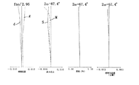
本数値実施例の断面図を図1に、広角端、中間位置、望遠端での収差図を図2、図3、図4に示す。
【0069】
本実施例は物体側から順に負の第1群、正の第2群、正の第3群、負の第4群で構成され広角端から望遠端へのズーミングに際し、第1群は像側に凸の往復運動、第2群は物体側へ移動、第3群、第4群は固定であり、第1群と第2群との間隔は狭まるよう、第2群と第3群の間隔は広がるように変化する。フォーカシングは第3群を物体側に繰出して遠距離物体から近距離物体への合焦を行う。
【0070】
以下レンズデータを示す。
【0071】
【外1】
(第2の実施例)
本数値実施例の断面図を図5に、広角端、中間位置、望遠端での収差図を図6、図7、図8に示す。本実施例は物体側から順に負の第1群、正の第2群、正の第3群、負の第4群で構成され、広角端から望遠端へのズーミングに際し、第1群は像側に凸の往復運動、第2群は物体側へ移動、第3群は像側へ移動、第4群は固定であり、第1群と第2群との間隔は狭まるよう、第2群と第3群の間隔は広がるよう、第3群と第4群の間隔は狭まるように変化する。フォーカシングは第3群を物体側に繰出して遠距離物体から近距離物体への合焦を行う。
【0073】
以下レンズデータを示す。
【0074】
【外2】
(第3の実施例)
本数値実施例の断面図を図9に、広角端、中間位置、望遠端での収差図を図10、図11、図12に示す。本実施例は物体側から順に負の第1群、正の第2群、正の第3群、負の第4群で構成され、広角端から望遠端へのズーミングに際し、第1群は像側に凸の往復運動、第2群は物体側へ移動、第3群は像側へ移動、第4群は固定であり、第1群と第2群との間隔は狭まるよう、第2群と第3群の間隔は広がるよう、第3群と第4群の間隔は狭まるように変化する。フォーカシングは第3群を物体側に繰出して遠距離物体から近距離物体への合焦を行う。
【0076】
以下レンズデータを示す。
【0077】
【外3】
(第4の実施例)
本数値実施例の断面図を図13に、広角端、中間位置、望遠端での収差図を図14、図15、図16に示す。本実施例は物体側から順に負の第1群、正の第2群、正の第3群、負の第4群で構成され、広角端から望遠端へのズーミングに際し、第1群は像側に凸の往復運動、第2群は物体側へ移動、第3群は像側へ移動、第4群は固定であり、第1群と第2群との間隔は狭まるよう、第2群と第3群の間隔は広がるよう、第3群と第4群の間隔は狭まるように変化する。フォーカシングは第3群を物体側に繰出して遠距離物体から近距離物体への合焦を行う。
【0079】
以下レンズデータを示す。
【0080】
【外4】
(第5の実施例)
本数値実施例の断面図を図17に、広角端、中間位置、望遠端での収差図を図18、図19、図20に示す。本実施例は物体側から順に負の第1群、正の第2群、正の第3群、負の第4群で構成され、広角端から望遠端へのズーミングに際し、第1群は像側に凸の往復運動、第2群は物体側へ移動、第3群は像側へ移動、第4群は固定であり、第1群と第2群との間隔は狭まるよう、第2群と第3群の間隔は広がるよう、第3群と第4群の間隔は広がるように変化する。フォーカシングは第3群を物体側に繰出して遠距離物体から近距離物体への合焦を行う。
【0082】
以下レンズデータを示す。
【0083】
【外5】
(第6の実施例)
本数値実施例の断面図を図21に、広角端、中間位置、望遠端での収差図を図22、図23、図24に示す。本実施例は物体側から順に負の第1群、正の第2群、正の第3群、負の第4群で構成され、広角端から望遠端へのズーミングに際し、第1群は像側に凸の往復運動、第2群は物体側へ移動、第3群は像側へ移動、第4群は固定であり、第1群と第2群との間隔は狭まるよう、第2群と第3群の間隔は広がるよう、第3群と第4群の間隔は広がるように変化する。フォーカシングは第3群を物体側に繰出して遠距離物体から近距離物体への合焦を行う。
【0085】
以下レンズデータを示す。
【0086】
【外6】
【発明の効果】
本発明によれば、インナーフォーカス式のネガティブリードタイプのズームレンズにおいて、フォーカス群の構成枚数が少なく、かつフォーカスストロークが短縮されるため、特にオートフォーカス式の撮像装置において高速で低消費電力なフォーカスが可能となるとともに、射出瞳を像面から十分に離し、固体撮像素子を用いた撮像装置に好適なズームレンズが提供できるという効果がある。
【図面の簡単な説明】
【図1】 本発明の撮像装置の基本構成を示す図(数値実施例1の光学断面図)。
【図2】 数値実施例1の広角端での収差図。
【図3】 数値実施例1の中間位置での収差図。
【図4】 数値実施例1の望遠端での収差図。
【図5】 数値実施例2の光学断面図。
【図6】 数値実施例2の広角端での収差図。
【図7】 数値実施例2の中間位置での収差図。
【図8】 数値実施例2の望遠端での収差図。
【図9】 数値実施例3の光学断面図。
【図10】 数値実施例3の広角端での収差図。
【図11】 数値実施例3の中間位置での収差図。
【図12】 数値実施例3の望遠端での収差図。
【図13】 数値実施例4の光学断面図。
【図14】 数値実施例4の広角端での収差図。
【図15】 数値実施例4の中間位置での収差図。
【図16】 数値実施例4の望遠端での収差図。
【図17】 数値実施例5の光学断面図。
【図18】 数値実施例5の広角端での収差図。
【図19】 数値実施例5の中間位置での収差図。
【図20】 数値実施例5の望遠端での収差図。
【図21】 数値実施例6の光学断面図。
【図22】 数値実施例6の広角端での収差図。
【図23】 数値実施例6の中間位置での収差図。
【図24】 数値実施例6の望遠端での収差図。
【符号の説明】
I 第1群
II 第2群
III 第3群
IV 第4群
S 絞り
G CCDのフェースプレートやローパスフィルター等のガラスブロック[0001]
BACKGROUND OF THE INVENTION
The present invention relates to a zoom lens suitable for an imaging apparatus using a solid-state image sensor or the like.
[0002]
[Prior art]
As video cameras and electronic still cameras using solid-state image sensors become more sophisticated, both high performance and downsizing are required.
[0003]
This type of camera requires a lens having a relatively long back focus because various optical members such as a low-pass filter and a color correction filter need to be disposed between the rearmost part of the lens and the image sensor. Furthermore, in the case of a camera using a color image sensor, a camera with good image side telecentric characteristics is desired to avoid color shading.
[0004]
Conventionally, various so-called short zoom type zoom lenses having two negative and positive groups have been proposed as compact zoom configurations. In these short zoom type optical systems, zooming is performed by moving the positive second group, and image point positions are corrected by zooming by moving the negative first group.
[0005]
In order to achieve higher performance and smaller size, as described in Japanese Patent Publication No. 7-3507, Japanese Patent Publication No. 6-40170, etc., a negative or positive third group is arranged on the image side to correct aberrations. An example is given. However, since these lens systems are mainly designed for 35 mm film photography, it is difficult to say that both the back focus length required for an optical system using a solid-state imaging device and good telecentric characteristics are compatible.
[0006]
[Problems to be solved by the invention]
Examples of the zoom lens system satisfying the back focus and the telecentric characteristics include an optical system having a negative-positive-positive three-group structure described in Japanese Patent Application Laid-Open No. 63-135913, Japanese Patent Application Laid-Open No. 7-261083, and the like. It is done. Japanese Patent Laid-Open No. 3-288113 discloses an optical system that performs zooming by moving a positive second group and a third group while fixing a negative one group in a negative-positive-positive three-group configuration. It is disclosed. However, these conventional examples have the disadvantages that the number of components in each group is relatively large, the total lens length is long, and the manufacturing cost is high.
[0007]
Further, in the example described in JP-A-7-261083, a convex lens is arranged on the most object side of the negative first group, and an increase in the outer diameter of the lens is especially unavoidable when the angle is widened. Had. Further, in this example, since the negative first group is moved to perform focusing on a short-distance object, there is a disadvantage that the mechanical structure becomes complicated in combination with the movement by zooming.
[0008]
U.S. Pat. No. 4,999,007 discloses a negative-positive-positive three-group configuration in which the first group and the second group are each composed of a single lens. However, the overall length of the lens at the wide-angle end is relatively large, and the first group at the wide-angle end is far away from the stop, so that the incident height of off-axis rays is large and the diameter of the lens constituting the first group increases. As a result, the entire lens system becomes large.
[0009]
In addition, since the first group and the second group have one component, aberration correction within the group was insufficient. In particular, the change in chromatic aberration of magnification at the time of zooming is likely to occur in the first group in which the height fluctuation of the off-axis light beam from the optical axis is large. However, since the first group is a single concave lens, correction within the group is possible. However, there is a problem that the chromatic aberration of magnification variation is large in the entire system.
[0010]
Furthermore, there is a problem of insufficient correction of distortion aberration as a particular problem when the angle of view at the wide angle end of the zoom is increased. Further, in order to use in a high-pixel imaging element having a relatively low sensitivity, a larger aperture ratio is required.
[0011]
U.S. Pat. No. 4,824,223 discloses a projector optical system having a negative-positive-positive three-group configuration. In this lens, since the first group is one negative lens, the aberration correction in the group is not performed, and the zoom ratio is about 1.7.
[0012]
In view of this, the present applicant has disclosed a photographic lens having a three-group configuration of negative-positive-positive in Japanese Patent Application No. 10-301684. In this photographic lens, while ensuring both the lens back necessary for inserting a filter and the telecentric characteristics necessary for a solid-state image sensor, the zoom lens is shortened as much as possible while maintaining a zoom ratio of 2 or more and is a compact zoom lens. Has achieved.
[0013]
In Japanese Patent Application No. 10-301684, the focusing method can be a so-called rear focus method in which the third lens group is extended toward the object side to perform focusing from a long distance to a short distance. The rear focus type and inner focus type have the advantage that the effective lens diameter of the first lens unit is smaller than that of the front lens focus, so that the entire lens system can be reduced in size. In addition, since focusing is performed by moving a relatively small and lightweight lens group, an autofocus camera has an advantage that quick focusing is possible.
[0014]
However, the negative-positive-positive three-group configuration has a problem that the focus sensitivity of the third lens group is relatively low. If the focus sensitivity is low, the amount of movement of the focus lens for focusing becomes large. Therefore, it is necessary to increase the moving speed of the focus lens in order to shorten the time until focusing. However, this is a problem because the drive device is increased in size and power consumption is increased.
[0015]
The focus sensitivity of the rear focus type is expressed by (1-β 2 ) where β is the lateral magnification of the focus group. In order to increase the focus sensitivity, it is effective to move the object point position of the focus group to the infinity side and to bring the image point position of the focus group closer to the focus group side. In order to realize the former, it is effective to make the light beam incident on the focus group close to afocal. In order to realize the latter, it is effective to increase the refractive power of the focus group.
[0016]
However, in the case of the negative-positive-positive three-group configuration, the refractive power of the second group having the main zooming action is relatively strong, so that the convergent light beam tends to enter the third group. Further, since the third group serves as a field lens, if the refractive power is increased too much, the degree of off-axis light beam bending becomes too strong, and good optical performance cannot be obtained with a small number of lenses. Therefore, conventionally, the sensitivity when focusing on the third group in the negative-positive-positive three-group configuration was not so high as about 0.5.
[0017]
Further, a zoom lens having a negative-positive-positive-negative four-group configuration is disclosed in Japanese Patent Laid-Open Nos. 6-175026 and 6-214156, but the negative refractive power of the fourth group is large. The exit pupil is too close to the image plane and is unsuitable for an imaging apparatus using a solid-state imaging device such as a CCD.
[0018]
Japanese Laid-Open Patent Application No. 8-248312 discloses a zoom lens having a negative-positive-positive-positive-negative four-group configuration, focusing on the positive second group. This is because the refractive power of the fourth group is relatively weak, but since the second group and the third group move with the same stroke at the time of zooming, the combined system of the second group and the third group plays a substantial zooming action. ing. Therefore, particularly on the telephoto side, the third lens unit is located on the object side, so that the action as a field lens is weak, and the exit pupil cannot be moved away from the image plane, which is also unsuitable for an image pickup apparatus using a solid-state image pickup device such as a CCD. It is.
[0019]
Therefore, the present invention is an inner focus type negative lead type zoom lens, which is a zoom lens suitable for an image pickup apparatus using a solid-state image pickup device in which the focus sensitivity is higher than the conventional one and the exit pupil is sufficiently separated from the image plane. For the purpose of provision.
[0020]
[Means for Solving the Problems]
The present invention solves the above problems with the following configuration.
[0021]
In order from the object side, the first group having a negative refractive power, the second group having a positive refractive power, the third group having a positive refractive power, and the fourth group having a negative refractive power are arranged from the wide-angle end to the telephoto end. In a zoom lens in which the distance between the first group and the second group is narrowed at the time of zooming, and the distance between the second group and the third group is widened, the first group is a negative lens with a concave surface facing the image side. The meniscus lens has a positive meniscus lens having a convex surface facing the object side, the second group has at least one positive lens and at least one negative lens, and the third group is moved to the object side to move away. Focusing from a distance object to a short distance object, the focal length of the third group is f3, the focal length of the fourth group is f4, and the focal length of the combined system of the third group and the fourth group at the wide angle end Is f34w, and the focal length of the entire system at the wide-angle end is fw,
3.0 <f34w / fw <5.2
1.5 <f3 / fw <3.0
2.0 <| f4 | / fw <10.0
A zoom lens characterized by satisfying the following conditions:
[0022]
DETAILED DESCRIPTION OF THE INVENTION
FIG. 1 shows a basic configuration of a zoom lens according to the present invention.
[0023]
In this embodiment, in order from the object side, there are four groups: a first group having a negative refractive power, a second group having a positive refractive power, a third group having a positive refractive power, and a fourth group having a negative refractive power. During zooming from the wide-angle end to the telephoto end, the first group moves reciprocally or partially moving toward the image side, the second group moves toward the object side, and the third group moves or Fixed, the fourth group is fixed. Therefore, from the wide-angle end toward the telephoto end, the first group and the second group are narrowed, and the second group and the third group are widened.
[0024]
In the zoom lens of the present invention, the negative first group and the positive second group basically constitute a so-called wide-angle short zoom system, and zooming is performed by the movement of the positive second group. The movement of the image point accompanying zooming is corrected by reciprocating the first group.
[0025]
S is an aperture stop, G is a glass plate, and IP is an image plane.
[0026]
The combined system of the third group and the fourth group of the zoom lens of the present invention has a positive refractive power. This achieves telecentric imaging on the image side, which is particularly necessary for an imaging apparatus using a solid-state imaging device or the like, by giving the third lens group and the fourth lens group the role of a field lens. That is, the third group and the fourth group of the present invention correspond to the three groups of the conventional negative-positive-positive three-group zoom lens.
[0027]
The zoom lens of the present invention is different from the negative-positive-positive three-group type in that the conventional positive third group is divided into a positive third group and a negative fourth group, and focusing is performed in the third group. It is a point.
[0028]
The focus sensitivity ES of the third group in the zoom lens of the present invention is expressed by the following equation when the lateral magnification of the third group is β3 and the lateral magnification of the fourth group is β4.
ES = (1-β3 2 ) × β4 2
[0029]
The focus sensitivity of the third group in the conventional negative-positive-positive three-group type is expressed by the following equation.
ES = (1-β3 2 )
[0030]
Each ES in the above formula is 0 when the absolute value of β3 is 1, and increases as the distance from 1 increases.
[0031]
If the main zooming action is shared by the second group, the refractive power of the second group increases to some extent, so that the convergent light beam is likely to enter the third group. In the case where the convergent light beam is incident on the third group having a positive refractive power, β3 in the above formula is in the following range.
0 <β3 <1
[0032]
In this case, the focus sensitivity ES increases as β3 decreases. In the zoom lens of the present invention, the amount corresponding to the refractive power of the third group in the conventional three-group configuration is replaced with the combined system of the third group and the fourth group, and the refractive power of the third group of the zoom lens of the present invention. Can be set larger than before. Therefore, the image point of the third group can be made closer to the third group side by increasing the refractive power of the third group. As a result, β3 becomes small, so that the focus sensitivity ES can be increased.
[0033]
Further, a convergent light beam is incident on the negative fourth group of the zoom lens of the present invention. At this time, β4 falls within the following range.
1 <β4
[0034]
Therefore, the zoom lens of the present invention further increases the focus sensitivity ES by β4 × 2 .
[0035]
In the zoom lens of the present invention, the third group may be moved during zooming. When the third group moves during zooming, the height from the optical axis of the off-axis rays incident on the third group can be controlled, so that the ability to correct off-axis aberrations is improved, and the entire zoom range is even better. Performance can be realized.
[0036]
Further, when the third lens unit moves toward the image side from the wide-angle end toward the telephoto end, the lateral magnification β3 of the third lens unit increases on the telephoto side. Therefore, the amount of movement of the second group can be shortened by the amount that can be shared by the third group, which contributes to downsizing of the entire lens system.
[0037]
Further, when the third lens unit moves toward the object side from the wide-angle end toward the telephoto end, the focus sensitivity increases on the telephoto side. Since the focus extension amount increases on the telephoto side than on the wide-angle side for a specific subject distance, the focusing time is longer on the telephoto side when the focus lens is driven at the same speed. This has the effect of making the focusing on the side even faster.
[0038]
In the zoom lens of the present invention, the third group and the fourth group are composed of one lens. If the third group is composed of one lens, the focus group is lightweight, so that high speed and low power consumption can be achieved in focusing. Further, the fourth group is composed of one concave lens, and the increase in the total lens length is suppressed to the minimum as compared with the conventional three-group configuration of negative-positive-positive.
[0039]
In the zoom lens of the present invention, the diaphragm is placed on the object side in the second group, and the distance between the entrance pupil and the first group on the wide-angle side is shortened, thereby increasing the outer diameter of the lens constituting the first group. By canceling various off-axis aberrations between the first group and the third group across the stop arranged on the object side of the positive second group, good optical performance can be obtained without increasing the number of components.
[0040]
The negative first group has a role of forming an off-axis chief ray at the center of the pupil and forms an off-axis aberration, particularly astigmatism, because the off-axis chief ray has a large amount of refraction especially at the wide angle side. And distortion is likely to occur. Therefore, a concave-convex configuration that can suppress an increase in the lens diameter closest to the object side as in a normal wide-angle lens is adopted. Each lens constituting the first group has a shape close to a concentric spherical surface centered on the stop center in order to suppress the occurrence of off-axis aberration caused by refraction of the off-axis principal ray. That is, the
[0041]
The
[0042]
Further, the
[0043]
Further, a cemented
[0044]
Further, in order to achieve further improvement in optical performance while forming each group with a small number of sheets, an aspherical surface is effectively introduced in this embodiment.
[0045]
In the embodiment shown in FIG. 1, the image side surface of the
[0046]
Further, the object side surface of the
[0047]
In addition, the object side surface of the
[0048]
Furthermore, it is preferable that the zoom lens of the present invention satisfies the following conditional expression.
[0049]
3.0 <f34w / fw <5.2 (1)
1.5 <f3 / fw <3.0 (2)
2.0 <| f4 | / fw <10.0 (3)
However, the focal length of the third group is f3, the focal length of the fourth group is f4, the focal length of the combined system of the third group and the fourth group at the wide angle end is f34w, and the focal length of the entire system at the wide angle end is fw. To do.
[0050]
Conditional expression (1) is an expression that defines the focal length, that is, the refractive power of the combined system of the third group and the fourth group. If the refractive power is weakened beyond the upper limit, the action of moving the exit pupil away from the image plane as a field lens system is weakened. Therefore, when a solid-state imaging device such as a CCD is used, the occurrence of shading becomes remarkable, which is not good.
[0051]
If the refractive power increases beyond the lower limit, it is not good because it is difficult to secure the back focus necessary for inserting the filter.
[0052]
Conditional expression (2) is an expression defining the focal length of the third group, that is, the refractive power. If the refractive power of the third group is weakened beyond the upper limit, the magnification of the third group increases, so the focus sensitivity of the third group decreases, and the third group of the conventional negative-positive-positive three-group configuration becomes positive. Since the effect divided into the third group and the negative fourth group is reduced, it is not good.
[0053]
If the refractive power of the third group is increased beyond the lower limit, the Petzval amount of the third group becomes positively larger, so that it is necessary to cancel this by increasing the refractive power of the fourth group. In this case, off-axis high-order aberrations are particularly prominent. Therefore, even if an aspherical surface is used, the third group and the fourth group are constituted by one lens, and the flatness of the image surface is obtained. It becomes difficult.
[0054]
Conditional expression (3) is an expression defining the focal length, that is, the refractive power of the fourth group. If the refractive power of the fourth group becomes weaker than the upper limit, the magnification of the fourth group becomes small, resulting in a decrease in focus sensitivity of the third group, and the third negative lens in the conventional negative-positive-positive three-group configuration. This is not good because the effect of dividing the group into a positive third group and a negative fourth group is diminished.
[0055]
If the refractive power of the fourth group is increased beyond the lower limit, the Petzval amount of the fourth group becomes negatively larger, so that it is necessary to cancel this by increasing the refractive power of the third group. In this case, off-axis high-order aberrations are particularly prominent. Therefore, even if an aspherical surface is used, the third group and the fourth group are constituted by one lens, and the flatness of the image surface is obtained. It becomes difficult.
[0056]
Furthermore, it is preferable that the following conditional expression is satisfied.
[0057]
−0.6 <(R32 + R31) / (R32−R31) <0.8 (4)
0.8 <R41 / R32 <20.0 (5)
However, the radius of curvature of the lens surface located closest to the object side in the third group is R31, the radius of curvature of the lens surface located closest to the image side in the third group is R32, and the lens surface located closest to the object side in the fourth group. Let R41 be the radius of curvature.
[0058]
Conditional expression (4) is an expression that prescribes the shape factor of the positive lens constituting the third group. When viewed from the object side, the convex lens is 1 for a convex plano lens, -1 for a plano-convex lens, and 1 is greater than -1 for a biconvex lens. Take a smaller value. If the third group has a refractive power defined by the conditional expression (2), if the upper limit of the conditional expression (4) is exceeded, the radius of curvature of the object side lens surface becomes too small, and the incidence of off-axis rays Since the corner becomes large, an excessive astigmatic difference occurs, which is not good.
[0059]
If the lower limit is exceeded, the radius of curvature of the image side lens surface becomes too small, and the incident angle of the axial land ray on the image side surface becomes large, resulting in insufficient correction of spherical aberration. In addition, when the third lens group is moved during zooming, spherical aberration fluctuations occur, and it becomes difficult to correct the entire zooming range even if an aspherical surface is used.
[0060]
Conditional expression (5) defines the ratio of the third group image side lens surface to the fourth group object side lens surface. If the curvature radius R41 exceeds the upper limit and the radius of curvature R41 becomes too large with respect to R32, in order for the fourth group to have the refractive power condition defined by the conditional expression (3), the negative refractive power of the fourth group is mainly used. It is necessary to share the image side lens surface. In this way, when the negative refractive power of the fourth group image side lens surface is strengthened, if the exit pupil is moved sufficiently away from the image plane, the effective diameters of the third group and fourth group object side lens surfaces are increased, and the lens outside the lens. Since the diameter increases, it is not good in terms of compactness. Further, in the optical axis direction, the back focus needs to be set long in order to prevent interference between the peripheral portion of the image-side lens surface of the fourth group and the filter disposed on the image side, which is not good because the total lens length increases.
[0061]
If the radius of curvature R41 is too small relative to R32 beyond the lower limit, R41 will be overcorrected with respect to the spherical aberration that occurs at R32. Further, during focusing, a fluctuation component of spherical aberration is generated particularly on the tele side where the amount of feeding is large.
[0062]
The values of the conditional expressions in the examples of the present invention are shown below.
[0063]
[Table 1]
The numerical examples of the present invention are shown below. In each numerical example, i indicates the order of the surfaces from the object side, Ri is the radius of curvature of the lens surface, Di is the lens thickness and air spacing between the i-th surface and the i-th eleventh surface, Ni, νi represents the refractive index and Abbe number for the d-line, respectively. The two surfaces closest to the image side are filter members such as a quartz low-pass filter and an infrared cut filter. B, C, D, E, and F are aspheric coefficients.
[0065]
The aspherical shape is when the displacement in the optical axis direction at the position of the height H from the optical axis is x with respect to the surface vertex.
[Expression 1]
It is represented by However, R is a radius of curvature and K is a conic constant.
[0068]
(First embodiment)
FIG. 1 is a sectional view of this numerical example, and FIGS. 2, 3, and 4 are aberration diagrams at the wide-angle end, the intermediate position, and the telephoto end.
[0069]
This embodiment is composed of a negative first group, a positive second group, a positive third group, and a negative fourth group in order from the object side. When zooming from the wide-angle end to the telephoto end, the first group is on the image side. The second group moves to the object side, the third group and the fourth group are fixed, and the distance between the second group and the third group is narrowed so that the distance between the first group and the second group is narrow. Changes to spread. In focusing, the third lens group is moved to the object side to focus from a long distance object to a short distance object.
[0070]
Lens data is shown below.
[0071]
[Outside 1]
(Second embodiment)
FIG. 5 is a cross-sectional view of the present numerical example, and FIGS. 6, 7, and 8 are aberration diagrams at the wide-angle end, the intermediate position, and the telephoto end. This embodiment is composed of a negative first group, a positive second group, a positive third group, and a negative fourth group in order from the object side. When zooming from the wide angle end to the telephoto end, the first group is an image. The second group moves so that the second group moves to the object side, the third group moves to the image side, the fourth group is fixed, and the distance between the first group and the second group is narrowed. The distance between the third group and the fourth group changes so that the distance between the third group and the third group increases. In focusing, the third lens group is moved to the object side to focus from a long distance object to a short distance object.
[0073]
Lens data is shown below.
[0074]
[Outside 2]
(Third embodiment)
FIG. 9 is a sectional view of this numerical example, and FIGS. 10, 11, and 12 are aberration diagrams at the wide-angle end, the intermediate position, and the telephoto end. This embodiment is composed of a negative first group, a positive second group, a positive third group, and a negative fourth group in order from the object side. When zooming from the wide angle end to the telephoto end, the first group is an image. The second group moves so that the second group moves to the object side, the third group moves to the image side, the fourth group is fixed, and the distance between the first group and the second group is narrowed. The distance between the third group and the fourth group changes so that the distance between the third group and the third group increases. In focusing, the third lens group is moved to the object side to focus from a long distance object to a short distance object.
[0076]
Lens data is shown below.
[0077]
[Outside 3]
(Fourth embodiment)
FIG. 13 is a cross-sectional view of this numerical example, and FIGS. 14, 15, and 16 are aberration diagrams at the wide-angle end, the intermediate position, and the telephoto end. This embodiment is composed of a negative first group, a positive second group, a positive third group, and a negative fourth group in order from the object side. When zooming from the wide angle end to the telephoto end, the first group is an image. The second group moves so that the second group moves to the object side, the third group moves to the image side, the fourth group is fixed, and the distance between the first group and the second group is narrowed. The distance between the third group and the fourth group changes so that the distance between the third group and the third group increases. In focusing, the third lens group is moved to the object side to focus from a long distance object to a short distance object.
[0079]
Lens data is shown below.
[0080]
[Outside 4]
(Fifth embodiment)
FIG. 17 is a sectional view of this numerical example, and FIGS. 18, 19, and 20 are aberration diagrams at the wide-angle end, the intermediate position, and the telephoto end. This embodiment is composed of a negative first group, a positive second group, a positive third group, and a negative fourth group in order from the object side. When zooming from the wide angle end to the telephoto end, the first group is an image. The second group moves so that the second group moves to the object side, the third group moves to the image side, the fourth group is fixed, and the distance between the first group and the second group is narrowed. The distance between the third group and the fourth group changes so that the distance between the third group and the third group widens. In focusing, the third lens group is moved to the object side to focus from a long distance object to a short distance object.
[0082]
Lens data is shown below.
[0083]
[Outside 5]
(Sixth embodiment)
FIG. 21 is a sectional view of this numerical example, and FIGS. 22, 23, and 24 are aberration diagrams at the wide-angle end, the intermediate position, and the telephoto end. This embodiment is composed of a negative first group, a positive second group, a positive third group, and a negative fourth group in order from the object side. When zooming from the wide angle end to the telephoto end, the first group is an image. The second group moves so that the second group moves to the object side, the third group moves to the image side, the fourth group is fixed, and the distance between the first group and the second group is narrowed. The distance between the third group and the fourth group changes so that the distance between the third group and the third group widens. In focusing, the third lens group is moved to the object side to focus from a long distance object to a short distance object.
[0085]
Lens data is shown below.
[0086]
[Outside 6]
【Effect of the invention】
According to the present invention, in an inner focus type negative lead type zoom lens, since the number of components of the focus group is small and the focus stroke is shortened, the focus is high speed and low power consumption particularly in an autofocus type imaging device. This makes it possible to provide a zoom lens suitable for an image pickup apparatus using a solid-state image pickup device by sufficiently separating the exit pupil from the image plane.
[Brief description of the drawings]
FIG. 1 is a diagram illustrating a basic configuration of an imaging apparatus according to the present invention (an optical cross-sectional view of Numerical Example 1).
FIG. 2 is an aberration diagram at the wide-angle end according to Numerical Example 1.
FIG. 3 is an aberration diagram at an intermediate position in Numerical Example 1.
FIG. 4 is an aberration diagram at the telephoto end according to Numerical Example 1.
FIG. 5 is an optical sectional view of Numerical Example 2.
FIG. 6 is an aberration diagram at the wide-angle end according to Numerical Example 2.
FIG. 7 is an aberration diagram at an intermediate position in Numerical Example 2.
FIG. 8 is an aberration diagram at a telephoto end according to Numerical Example 2.
FIG. 9 is an optical sectional view of Numerical Example 3.
FIG. 10 is an aberration diagram at the wide-angle end according to Numerical Example 3.
FIG. 11 is an aberration diagram at an intermediate position in Numerical Example 3.
12 is an aberration diagram at a telephoto end according to Numerical Example 3. FIG.
13 is an optical sectional view of Numerical Example 4. FIG.
FIG. 14 is an aberration diagram for Numerical Example 4 at the wide-angle end.
FIG. 15 is an aberration diagram at an intermediate position in Numerical Example 4.
FIG. 16 is an aberration diagram at a telephoto end according to Numerical Example 4.
FIG. 17 is an optical sectional view of Numerical Example 5.
FIG. 18 shows aberration diagrams at the wide-angle end of Numerical Example 5.
FIG. 19 is an aberration diagram at an intermediate position in Numerical Example 5.
FIG. 20 is an aberration diagram at a telephoto end according to Numerical Example 5.
FIG. 21 is an optical sectional view of Numerical Example 6.
FIG. 22 is an aberration diagram for Numerical Example 6 at the wide-angle end.
FIG. 23 is an aberration diagram at an intermediate position in Numerical Example 6.
24 is an aberration diagram at a telephoto end according to Numerical Example 6. FIG.
[Explanation of symbols]
I 1st group II 2nd group III 3rd group IV 4th group S Aperture G Glass blocks such as CCD face plates and low-pass filters
Claims (8)
3.0<f34w/fw<5.2
1.5<f3/fw<3.0
2.0<|f4|/fw<10.0
なる条件を満足することを特徴とするズームレンズ。In order from the object side, the first group having a negative refractive power, the second group having a positive refractive power, the third group having a positive refractive power, and the fourth group having a negative refractive power are arranged from the wide-angle end to the telephoto end. narrowing the interval between the second group and the first group during zooming, the zoom lens interval extends between the third group and the second group, the first group of negative having a concave surface facing the image side has a meniscus lens, a positive having a convex surface directed toward the object side meniscus lens, the second group has at least one negative lens and at least one positive lens, the far the third group move to the object side Focusing from a distance object to a short distance object, the focal length of the third group is f3, the focal length of the fourth group is f4, and the focal length of the combined system of the third group and the fourth group at the wide angle end Is f34w, and the focal length of the entire system at the wide-angle end is fw,
3.0 <f34w / fw <5.2
1.5 <f3 / fw <3.0
2.0 <| f4 | / fw <10.0
A zoom lens characterized by satisfying the following conditions:
−0.6<(R32+R31)/(R32−R31)<0.8
0.8<R41/R32<20.0
なる条件を満足することを特徴とする請求項1乃至4のいずれか1項に記載のズームレンズ。The radius of curvature of the lens surface located closest to the object side of the third group is R31, the radius of curvature of the lens surface located closest to the image side of the third group is R32, and the lens located closest to the object side of the fourth group. When the curvature radius of the surface is R41,
−0.6 <(R32 + R31) / (R32−R31) <0.8
0.8 <R41 / R32 <20.0
The zoom lens according to claim 1 , wherein the following condition is satisfied.
Priority Applications (1)
| Application Number | Priority Date | Filing Date | Title |
|---|---|---|---|
| JP2001236285A JP4817551B2 (en) | 2001-08-03 | 2001-08-03 | Zoom lens |
Applications Claiming Priority (1)
| Application Number | Priority Date | Filing Date | Title |
|---|---|---|---|
| JP2001236285A JP4817551B2 (en) | 2001-08-03 | 2001-08-03 | Zoom lens |
Publications (3)
| Publication Number | Publication Date |
|---|---|
| JP2003043358A JP2003043358A (en) | 2003-02-13 |
| JP2003043358A5 JP2003043358A5 (en) | 2008-09-18 |
| JP4817551B2 true JP4817551B2 (en) | 2011-11-16 |
Family
ID=19067582
Family Applications (1)
| Application Number | Title | Priority Date | Filing Date |
|---|---|---|---|
| JP2001236285A Expired - Fee Related JP4817551B2 (en) | 2001-08-03 | 2001-08-03 | Zoom lens |
Country Status (1)
| Country | Link |
|---|---|
| JP (1) | JP4817551B2 (en) |
Families Citing this family (8)
| Publication number | Priority date | Publication date | Assignee | Title |
|---|---|---|---|---|
| JP4508604B2 (en) * | 2003-11-06 | 2010-07-21 | キヤノン株式会社 | Zoom lens and imaging apparatus having the same |
| JP4508610B2 (en) * | 2003-11-17 | 2010-07-21 | オリンパス株式会社 | Variable magnification optical system and electronic apparatus using the same |
| WO2005047952A1 (en) * | 2003-11-17 | 2005-05-26 | Olympus Corporation | A variable-power optical system and electronic device using same |
| JP2007286548A (en) | 2006-04-20 | 2007-11-01 | Sharp Corp | Zoom lens, digital camera, and portable information device |
| WO2014007298A1 (en) * | 2012-07-03 | 2014-01-09 | 株式会社タムロン | Zoom lens |
| CN103197409B (en) * | 2013-04-01 | 2017-12-26 | 东莞市宇瞳光学科技股份有限公司 | Optical compensation zoom lens |
| JP6883226B2 (en) * | 2016-11-08 | 2021-06-09 | ソニーグループ株式会社 | Imaging lens and imaging device |
| JP7009138B2 (en) * | 2017-09-26 | 2022-01-25 | キヤノン株式会社 | Zoom lens and image pickup device with it |
Family Cites Families (2)
| Publication number | Priority date | Publication date | Assignee | Title |
|---|---|---|---|---|
| JPS58160912A (en) * | 1982-03-19 | 1983-09-24 | Canon Inc | Zoom lens |
| JP2850548B2 (en) * | 1991-01-19 | 1999-01-27 | キヤノン株式会社 | Zoom lens |
-
2001
- 2001-08-03 JP JP2001236285A patent/JP4817551B2/en not_active Expired - Fee Related
Also Published As
| Publication number | Publication date |
|---|---|
| JP2003043358A (en) | 2003-02-13 |
Similar Documents
| Publication | Publication Date | Title |
|---|---|---|
| JP3599689B2 (en) | Zoom lens | |
| JP4173977B2 (en) | Zoom lens system | |
| JP2001033703A (en) | Rear focus type zoom lens | |
| JP5767335B2 (en) | Zoom lens and imaging device | |
| JP2006343552A (en) | Zoom lens and imaging apparatus having the same | |
| JP4902179B2 (en) | Zoom lens and imaging apparatus having the same | |
| WO2013031180A1 (en) | Zoom lens and imaging device | |
| JP2006139187A (en) | Zoom lens | |
| JP5767330B2 (en) | Zoom lens and imaging device | |
| JP2005134746A (en) | Zoom lens and imaging unit having the same | |
| JP4817551B2 (en) | Zoom lens | |
| JP4838899B2 (en) | Zoom lens and optical apparatus using the same | |
| JP4585796B2 (en) | Zoom lens and imaging apparatus having the same | |
| JP4537114B2 (en) | Zoom lens | |
| JP3706827B2 (en) | Zoom lens and optical apparatus having the same | |
| JP5767710B2 (en) | Zoom lens and imaging device | |
| JP5767334B2 (en) | Zoom lens and imaging device | |
| JP5767333B2 (en) | Zoom lens and imaging device | |
| JP5767332B2 (en) | Zoom lens and imaging device | |
| WO2013031183A1 (en) | Zoom lens and imaging device | |
| WO2013031182A1 (en) | Zoom lens and imaging device | |
| WO2013031179A1 (en) | Zoom lens and imaging device | |
| JP2006099130A (en) | Zoom lens | |
| JPWO2013031178A1 (en) | Zoom lens and imaging device | |
| JP4580510B2 (en) | Zoom lens |
Legal Events
| Date | Code | Title | Description |
|---|---|---|---|
| RD01 | Notification of change of attorney |
Free format text: JAPANESE INTERMEDIATE CODE: A7421 Effective date: 20080703 |
|
| A521 | Written amendment |
Free format text: JAPANESE INTERMEDIATE CODE: A523 Effective date: 20080804 |
|
| A621 | Written request for application examination |
Free format text: JAPANESE INTERMEDIATE CODE: A621 Effective date: 20080804 |
|
| RD04 | Notification of resignation of power of attorney |
Free format text: JAPANESE INTERMEDIATE CODE: A7424 Effective date: 20100201 |
|
| RD01 | Notification of change of attorney |
Free format text: JAPANESE INTERMEDIATE CODE: A7421 Effective date: 20100630 |
|
| A977 | Report on retrieval |
Free format text: JAPANESE INTERMEDIATE CODE: A971007 Effective date: 20110518 |
|
| A131 | Notification of reasons for refusal |
Free format text: JAPANESE INTERMEDIATE CODE: A131 Effective date: 20110524 |
|
| A521 | Written amendment |
Free format text: JAPANESE INTERMEDIATE CODE: A523 Effective date: 20110725 |
|
| TRDD | Decision of grant or rejection written | ||
| A01 | Written decision to grant a patent or to grant a registration (utility model) |
Free format text: JAPANESE INTERMEDIATE CODE: A01 Effective date: 20110823 |
|
| A01 | Written decision to grant a patent or to grant a registration (utility model) |
Free format text: JAPANESE INTERMEDIATE CODE: A01 |
|
| A61 | First payment of annual fees (during grant procedure) |
Free format text: JAPANESE INTERMEDIATE CODE: A61 Effective date: 20110830 |
|
| FPAY | Renewal fee payment (event date is renewal date of database) |
Free format text: PAYMENT UNTIL: 20140909 Year of fee payment: 3 |
|
| FPAY | Renewal fee payment (event date is renewal date of database) |
Free format text: PAYMENT UNTIL: 20140909 Year of fee payment: 3 |
|
| LAPS | Cancellation because of no payment of annual fees |