JP4817549B2 - Page description rendering method and system - Google Patents
Page description rendering method and system Download PDFInfo
- Publication number
- JP4817549B2 JP4817549B2 JP2001229426A JP2001229426A JP4817549B2 JP 4817549 B2 JP4817549 B2 JP 4817549B2 JP 2001229426 A JP2001229426 A JP 2001229426A JP 2001229426 A JP2001229426 A JP 2001229426A JP 4817549 B2 JP4817549 B2 JP 4817549B2
- Authority
- JP
- Japan
- Prior art keywords
- render
- current
- rendering
- instruction set
- render instruction
- Prior art date
- Legal status (The legal status is an assumption and is not a legal conclusion. Google has not performed a legal analysis and makes no representation as to the accuracy of the status listed.)
- Expired - Fee Related
Links
Images


Classifications
-
- G—PHYSICS
- G06—COMPUTING; CALCULATING OR COUNTING
- G06F—ELECTRIC DIGITAL DATA PROCESSING
- G06F3/00—Input arrangements for transferring data to be processed into a form capable of being handled by the computer; Output arrangements for transferring data from processing unit to output unit, e.g. interface arrangements
- G06F3/12—Digital output to print unit, e.g. line printer, chain printer
- G06F3/1201—Dedicated interfaces to print systems
- G06F3/1202—Dedicated interfaces to print systems specifically adapted to achieve a particular effect
- G06F3/1218—Reducing or saving of used resources, e.g. avoiding waste of consumables or improving usage of hardware resources
- G06F3/122—Reducing or saving of used resources, e.g. avoiding waste of consumables or improving usage of hardware resources with regard to computing resources, e.g. memory, CPU
-
- G—PHYSICS
- G06—COMPUTING; CALCULATING OR COUNTING
- G06F—ELECTRIC DIGITAL DATA PROCESSING
- G06F3/00—Input arrangements for transferring data to be processed into a form capable of being handled by the computer; Output arrangements for transferring data from processing unit to output unit, e.g. interface arrangements
- G06F3/12—Digital output to print unit, e.g. line printer, chain printer
- G06F3/1201—Dedicated interfaces to print systems
- G06F3/1202—Dedicated interfaces to print systems specifically adapted to achieve a particular effect
- G06F3/1203—Improving or facilitating administration, e.g. print management
- G06F3/1208—Improving or facilitating administration, e.g. print management resulting in improved quality of the output result, e.g. print layout, colours, workflows, print preview
-
- G—PHYSICS
- G06—COMPUTING; CALCULATING OR COUNTING
- G06F—ELECTRIC DIGITAL DATA PROCESSING
- G06F3/00—Input arrangements for transferring data to be processed into a form capable of being handled by the computer; Output arrangements for transferring data from processing unit to output unit, e.g. interface arrangements
- G06F3/12—Digital output to print unit, e.g. line printer, chain printer
- G06F3/1201—Dedicated interfaces to print systems
- G06F3/1202—Dedicated interfaces to print systems specifically adapted to achieve a particular effect
- G06F3/121—Facilitating exception or error detection and recovery, e.g. fault, media or consumables depleted
-
- G—PHYSICS
- G06—COMPUTING; CALCULATING OR COUNTING
- G06F—ELECTRIC DIGITAL DATA PROCESSING
- G06F3/00—Input arrangements for transferring data to be processed into a form capable of being handled by the computer; Output arrangements for transferring data from processing unit to output unit, e.g. interface arrangements
- G06F3/12—Digital output to print unit, e.g. line printer, chain printer
- G06F3/1201—Dedicated interfaces to print systems
- G06F3/1223—Dedicated interfaces to print systems specifically adapted to use a particular technique
- G06F3/1229—Printer resources management or printer maintenance, e.g. device status, power levels
- G06F3/1234—Errors handling and recovery, e.g. reprinting
- G06F3/1235—Errors handling and recovery, e.g. reprinting caused by end of consumables, e.g. paper, ink, toner
-
- G—PHYSICS
- G06—COMPUTING; CALCULATING OR COUNTING
- G06F—ELECTRIC DIGITAL DATA PROCESSING
- G06F3/00—Input arrangements for transferring data to be processed into a form capable of being handled by the computer; Output arrangements for transferring data from processing unit to output unit, e.g. interface arrangements
- G06F3/12—Digital output to print unit, e.g. line printer, chain printer
- G06F3/1201—Dedicated interfaces to print systems
- G06F3/1223—Dedicated interfaces to print systems specifically adapted to use a particular technique
- G06F3/1237—Print job management
-
- G—PHYSICS
- G06—COMPUTING; CALCULATING OR COUNTING
- G06F—ELECTRIC DIGITAL DATA PROCESSING
- G06F3/00—Input arrangements for transferring data to be processed into a form capable of being handled by the computer; Output arrangements for transferring data from processing unit to output unit, e.g. interface arrangements
- G06F3/12—Digital output to print unit, e.g. line printer, chain printer
- G06F3/1201—Dedicated interfaces to print systems
- G06F3/1278—Dedicated interfaces to print systems specifically adapted to adopt a particular infrastructure
- G06F3/1284—Local printer device
Landscapes
- Engineering & Computer Science (AREA)
- Theoretical Computer Science (AREA)
- Physics & Mathematics (AREA)
- Human Computer Interaction (AREA)
- General Engineering & Computer Science (AREA)
- General Physics & Mathematics (AREA)
- Mathematical Physics (AREA)
- Quality & Reliability (AREA)
- Record Information Processing For Printing (AREA)
- Accessory Devices And Overall Control Thereof (AREA)
- Image Generation (AREA)
Description
【0001】
【発明の属する技術分野】
本発明は、ページ記述をレンダリングするための方法およびシステムに関する。本発明はまた、ページ記述をレンダリングするためのコンピュータ・プログラムにも関する。
【0002】
【従来の技術】
比較的近年、印刷ページをプリンタ、表示画面および/または他のロケーション(たとえば、ファイル)にレンダリングするためのグラフィックス・パッケージが存在している。これらのいくつかのグラフィックス・パッケージは、典型的には、高レベルのページ記述言語を、印刷ページのレイアウトにおいて支援するために利用するものである。これらのグラフィックス・パッケージは典型的にはレンダリング・システムを含み、これがページ・レイアウトの高レベルのページ記述を、印刷及び/又は表示されるラスタ・データとして使用することができる画素データに変換する。
【0003】
1つのこのようなレンダリング・システムは、ページまたは画面の画素に基づいたイメージを保持するためのフルページ・フレーム・ストアを含む。フルページ・フレーム・ストアはバッファであり、ページ全体についてプリンタに送信する必要のあるあらゆる画素のための空間を有する。これらのシステムでは、高レベルのページ記述において受信されるあらゆるオブジェクトを、直ちにレンダリングすることができる。このシステムの主要な問題は、フレーム・ストアのために必要となるメモリが非常に大きいことであり、特に、各画素を連続色調にする必要があり、これが関連付けられた透過値を有する可能性があるときにそうである。
【0004】
【発明が解決しようとする課題】
オブジェクトをz順序で順次に適用するというより、むしろレンダリストに適用されたときに、速度においてもメモリ使用においてもより効率的に実行する既存のレンダリング・システムがる。このようなシステムは、レンダリストに必要とされる記憶装置が使用可能なリソース以内であるときに大変有利であるが、さらにリソースが必要となる場合、中断してしまう。たとえば、オブジェクト・レンダリストのサイズに制限がないのに対して、フレーム・ストアのサイズは大きいが制限されており、厳密に印刷ページの解像度およびサイズによって決まる。このようなシステムを使用するとき、これらは、使用可能なリソースを越えるレンダリストと共に提示されたときに障害を起こすか、あるいは、フレーム・ストアを使用したオブジェクト順次即時レンダリング方法へと劣化する。
【0005】
本発明の一目的は、既存の構成の1つまたは複数の欠点を実質的に克服、あるいは少なくとも改良することである。
【0006】
【課題を解決するための手段】
本発明の第1の態様によれば、レンダリングシステム上でページ記述をレンダリングする方法を提供する。ここで、ページ記述は1つまたは複数のオブジェクトを含むものであり、この方法は、オブジェクトを下から上へのz順に順次受信するステップと、1つまたは複数のレンダ命令セットを生成するステップとを含み、この生成するステップは、受信された各オブジェクトについて、現在の受信されたオブジェクトが対応するレンダ命令を現レンダ命令セットに追加することにより、レンダリング・システムのリソースを越えるかどうかを決定するサブステップと、リソースを越える場合、新しいレンダ命令セットを作成するサブステップと、レンダ命令を新しいレンダ命令セットに追加して現レンダ命令セットを背景イメージとして描画するサブステップと、新しいレンダ命令セットに、現在の受信されたオブジェクトが対応するレンダ命令を追加するサブステップとを実行するサブステップと、リソースを越えない場合、現在の受信されたオブジェクトが対応するレンダ命令を現レンダ命令セットに追加するサブステップを実行するサブステップとを実行し、さらに、1つまたは複数のレンダ命令セットを画素データとしてレンダリングするステップを含む。
【0007】
本発明の第2の態様によれば、ページ記述をレンダリングする方法を提供する。ここで、ページ記述は1つまたは複数のオブジェクトを含むものであり、この方法は、オブジェクトを下から上へのz順に順次受信するステップを含み、この方法は、受信された各オブジェクトについて、受信されたオブジェクトが現在のレンダリストに追加された場合にリソースを越えるかどうかを検査し、そうであった場合、現在のレンダリストをフレーム・ストア上にレンダリングし、次いで現在のレンダリストを空に設定するサブステップと、受信されたオブジェクトを現在のレンダリストに追加し、受信されたオブジェクトがz順における最後のオブジェクトであった場合、フレーム・ストア上にレンダリングされた場合、現在のレンダリストをフレーム・ストアと組み合わせてレンダリングして、レンダリングされたページ記述を形成し、そうでない場合、現在のレンダリストをレンダリングして、レンダリングされたページ記述を形成するサブステップとを実行する。
【0008】
本発明の第3の態様によれば、ページ記述をレンダリングするためのシステムを提供する。ここで、ページ記述は1つまたは複数のオブジェクトを含むものであり、このシステムは、オブジェクトを下から上へのz順に順次に受信する手段と、1つまたは複数のレンダ命令セットを生成する手段とを含み、この生成する手段は、受信された各オブジェクトについて、現在の受信されたオブジェクトが対応するレンダ命令を、現レンダ命令セットに追加することにより、レンダリングするためのシステムのリソースを越えるかどうかを決定する手段と、リソースを越える場合、新しいレンダ命令セットを作成する手段と、リソースを越える場合、レンダ命令を新しいレンダ命令セットに追加して現レンダ命令セットを背景イメージとして描画する手段と、リソースを越える場合、新しいレンダ命令セットに、現在の受信されたオブジェクトが対応するレンダ命令を追加する手段と、リソースを越えない場合、現在の受信されたオブジェクトの対応するレンダ命令を現レンダ命令セットに追加する手段と、1つまたは複数のレンダ命令セットを画素データとしてレンダリングする手段とを含む。
【0009】
本発明の第4の態様によれば、ページ記述をレンダリングするためのシステムを提供する。ここで、ページ記述は1つまたは複数のオブジェクトを含むものであり、このシステムは、オブジェクトを下から上へのz順に順次受信する手段と、受信された各オブジェクトについて、受信されたオブジェクトが現在のレンダリストに追加された場合にリソースを越えるかどうかを検査し、そうであった場合、現在のレンダリストをフレーム・ストア上にレンダリングし、次いで現在のレンダリストを空に設定する手段と、受信されたオブジェクトを現在のレンダリストに追加する手段と、受信されたオブジェクトがz順における最後のオブジェクトであり、フレーム・ストア上にレンダリングされた場合、現在のレンダリストをフレーム・ストアと組み合わせてレンダリングして、レンダリングされたページ記述を形成する手段と、受信されたオブジェクトがz順における最後のオブジェクトであり、フレーム・ストア上にレンダリングされなかった場合、現在のレンダリストをレンダリングして、レンダリングされたページ記述を形成する手段とを含む。
【0010】
本発明の第5の態様によれば、ページ記述をレンダリングするためのコンピュータ・プログラムを提供する。ここでページ記述は1つまたは複数のオブジェクトを含むものである。そして、このコンピュータ・プログラムは、コンピュータに、オブジェクトを下から上へのz順に順次に受信する手順と、1つまたは複数のレンダ命令セットを生成する手順とを含み、この生成するための手順は、受信された各オブジェクトについて、現在の受信されたオブジェクトが対応するレンダ命令を現レンダ命令セットに追加することにより、レンダリング・システムのリソースを越えるかどうかを決定する手順と、リソースを越える場合、新しいレンダ命令セットを作成する手順と、リソースを越える場合、レンダ命令を新しいレンダ命令セットに追加して現レンダ命令セットを背景イメージとして描画する手順と、リソースを越える場合、新しいレンダ命令セットに、現在の受信されたオブジェクトが対応するレンダ命令を追加する手順と、リソースを越えない場合、現在の受信されたオブジェクトの対応するレンダ命令を現レンダ命令セットに追加する手順とを含み、さらに、1つまたは複数のレンダリング命令セットを画素データとしてレンダリングする手順を実行させる。
【0011】
本発明の第6の態様によれば、ページ記述をレンダリングするためのコンピュータ・プログラムを提供する。ここでページ記述は1つまたは複数のオブジェクトを含むものである。そして、このコンピュータ・プログラムは、コンピュータに、オブジェクトを下から上へのz順に順次受信する手順と、受信された各オブジェクトについて、受信されたオブジェクトが現在のレンダリストに追加された場合にリソースを越えるかどうかを検査し、そうであった場合、現在のレンダリストをフレーム・ストア上にレンダリングし、次いで現在のレンダリストを空に設定する手順と、受信されたオブジェクトを現在のレンダリストに追加する手順と、受信されたオブジェクトがz順における最後のオブジェクトであり、フレーム・ストア上にレンダリングされた場合、現在のレンダリストをフレーム・ストアと組み合わせてレンダリングして、レンダリングされたページ記述を形成する手順と、受信されたオブジェクトがz順における最後のオブジェクトであり、フレーム・ストア上にレンダリングされなかった場合、現在のレンダリストをレンダリングして、レンダリングされたページ記述を形成する手順を実行させる。
【0012】
【発明の実施の形態】
本発明のいくつかの好ましい実施形態を、以下、図面を参照して記載する。
【0013】
1つまたは複数の添付の図面のいずれにおいても、同じ参照番号を有するステップおよび/または機能を参照する場合、これらのステップおよび/または機能は、反対の意図が現れない限り、この説明のために同じ機能または動作を有する。
【0014】
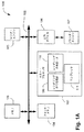
図1は、印刷されるラスタ・データとして使用される高レベルのページ記述を、画素にレンダリングかつ提示するために構成されるコンピュータ・システム100を示している。コンピュータ・システム100は、ホスト・プロセッサ102を含み、これはシステム・ランダム・アクセス・メモリ(RAM)103、フォント・メモリ104、レンダ・エンジン105、出力デバイス106およびプリンタ・エンジン107に関連付けられる。コンピュータ・システム100は、レンダリング命令生成部ソフトウェア・モジュール109、レンダリング命令ローダ・ソフトウェア・モジュール110、およびホスト・プロセッサ102上で動作するためのコンプレッサ・ソフトウェア・モジュール111も含む。レンダリング命令生成部ソフトウェア・モジュール109、レンダリング命令ローダ・ソフトウェア・モジュール110、およびコンプレッサ・ソフトウェア・モジュール111は、別法としてハードウェアにおいて実施することができ、バス・システム108に結合するか、あるいは、ローカル・バス(図示せず)と相互結合することができる。加えて、レンダ・エンジン105は、別法として、ホスト・プロセッサ102上で動作するためのソフトウェア・モジュールとして実施することができる。RAMメモリ103は、レンダリング命令生成部ソフトウェア・モジュール109によって生成された、1つまたは複数のレンダ命令セットの命令待ち行列112を格納するように適合される。フォント・メモリ104は、その中に1つまたは複数のフォントのフォント文字を格納しており、これらがレンダリング・エンジン105によって使用される。レンダ命令生成部109は、1つまたは複数のレンダリング命令セットを、高レベルのページ記述に応答して生成し、これらをRAMメモリ103における命令待ち行列112上にキューイングする。レンダリング命令ローダ・ソフトウェア・モジュール110は、これらの命令セットを一度に一セット、命令待ち行列112から取り、これをレンダリング・エンジン105にロードし、これが、これらの命令を画素として出力デバイス106およびプリンタ・エンジン107へ出力する。レンダ・エンジン105は時として、命令セットを出力デバイス106へレンダリングする代りに、命令セットをイメージとしてコンプレッサ・ソフトウェア・モジュール111へレンダリングする。コンプレッサ・ソフトウェア・モジュール111はこのイメージを圧縮し、これをメモリ103における命令待ち行列112へ戻すように供給し、これが後にレンダ・エンジン105によって使用される。
【0015】
上述のコンピュータ・システム100のハードウェア構成要素は、バス・システム108を介して相互接続され、IBM PC/ATタイプのパーソナル・コンピュータおよびそれから発展させられた構成、Sun Sparcstationsなど、当技術分野でよく知られているコンピュータ・システムの通常の動作モードにおいて動作可能である。コンピュータ・システム100の構成要素は、分離したコンピューティング環境においても存在できる。これらのソフトウェア・モジュールは、フロッピー・ディスク、光ディスク、メモリ・カードまたは他の適切な媒体など、コンピュータ可読媒体上に格納できることが好ましい。
【0016】
代替実施形態では、レンダ・エンジン105が生成した画素データを任意選択的に、直接、命令待ち行列112へ送信して圧縮しないようにすることができる。もう1つの実施形態では、画素データを、後にレンダ・エンジン105によって使用するために、レンダ・エンジン105自体内で保つことができる。命令待ち行列またはレンダ命令ローダがない、他の実施形態が可能である。これらの場合、レンダ命令生成部109が同期的に命令をレンダ・エンジン105にロードする。さらにもう1つの実施形態では、レンダ命令生成部109が、分離したコンピュータに位置し、ネットワークまたはある他の種類のデータ・リンクを介して、命令待ち行列112および/またはレンダ・エンジン105を含むコンピュータに結合されることが可能である。加えて、コンピュータ・システム100は、ページ記述のためのフロー制御を利用することが好ましい。つまり、レンダ・リスト生成部109がページ記述データを受信できない場合、レンダ・リスト生成部109がそれを受信する準備ができるまで、ページ記述データが汚染されないように、データの損失がないようにされる。
【0017】
高レベルのページ記述は、POSTSCRIPT言語など、印刷ページのレイアウトをz順序で配列されたオブジェクトの形式で記述するための、いかなる知られている高レベルのページ記述言語にすることもできる。
【0018】
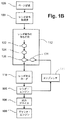
このとき、図1Bを参照して、図1Aのコンピュータ・システムの機能的データ・フローを示すブロック図を示す。ホスト・プロセッサ102が高レベルのページ記述120を受信する。このような高レベルのページ記述120は、ホスト・プロセッサ102上で動作するグラフィックス・パッケージによって、あるいは、ネットワークを介してこれに接続された、ある他のホスト・プロセッサ上のグラフィックス・アプリケーションから供給することができる。次いで、レンダ命令生成部109が1つまたは複数のレンダリング命令セット(122、124、126)を、高レベルのページ記述120に応答して生成し、これについては以下でより詳細に記載する。これらの1つまたは複数のレンダリング命令セット(122、124、126)が、メモリ103における命令待ち行列112上にキューイングされる。次いで、レンダ命令ローダ110が、これらの1つまたは複数のレンダリング命令セット(122、124、126)を一度に一セット、命令待ち行列112からロードし、これについては以下でより詳細に記載する。次いで、レンダ・エンジン105が1つまたは複数のレンダリング命令セットをレンダリングし、これについては以下でより詳細に記載する。レンダリング・エンジン105が出力画素(イメージ)を出力デバイス106およびプリンタ・エンジン107へ供給する。レンダリング・エンジン105は、ある条件において、出力画素(イメージ)を出力デバイス106へ供給する代りに、これらをコンプレッサ111へ供給する。コンプレッサ111はこのイメージ128を圧縮し、これが命令待ち行列112へ戻すように供給され、後にレンダ・エンジン105によって使用される。コンピュータ・システム100はパイプライン方式で動作し、レンダ命令生成部110およびレンダリング命令ローダは、同時かつ非同期的な方法で動作することができる。
【0019】
図1Cを参照すると、同図は図1Aのコンピュータ・システムの動作を例示するための、例示的ページ記述のオブジェクトおよび対応する変換されたオブジェクトを示している。レンダ命令生成部109が、ページ記述のオブジェクト(0、1、2、3、4、5、6および7)を一度に1つ、最低オブジェクト(0)から開始してz順序の増分において(すなわち、下から上へ)受信する。レンダ命令生成部109は最初に、ページ記述のための最初のレンダリング命令セットを生成する。この最初の命令セットは、典型的には、ページのレンダリングに必要ないかなる基本命令をも含む。次いで、レンダ命令生成部109が、基本命令および最下位オブジェクト(0)に対応するレンダリング命令を含む命令セットがコンピュータ・システム100のリソース制限を越えさせるかどうかを決定する。この例では、レンダ命令生成部109が、この命令セットではリソース制限を越えないと決定する。次いで、レンダ命令生成部109が、基本レンダリング命令、次の最低オブジェクト(1)に対応するレンダリング命令、および、最低オブジェクト(0)に対応するレンダリング命令を含む命令セットがコンピュータ・システム100のリソース制限を越えさせるかどうかを決定する。この例では、レンダ命令生成部109が、この命令セットではリソース制限を越えないと決定する。レンダ命令生成部109は、リソース制限がこのセットによって越えられると決定するまで、命令をそのセットに追加し続ける。この例では、レンダ命令生成部109が、この組の命令が基本レンダリング命令およびオブジェクト(0、1、2、3、4、5および6)のためのレンダリング命令を含むとき、リソース制限を最初に越えると決定する。次いで、レンダリング命令生成部109が、基本レンダリング命令およびオブジェクト(0、1、2、3、4および5)のためのレンダリング命令を含む命令セットをレンダ・エンジン105へ、好ましくは命令待ち行列112およびレンダリング命令ローダ110を介して供給する。
【0020】
次いで、レンダ命令生成部109が新しい初期の基本命令セットを作成し、最初にレンダリング命令を追加して、背景イメージを、オブジェクト(0、1、2、3、4および5)に対応するページ上に描画し、これを図1Cでオブジェクト0’として示す。これらのレンダリング命令は背景イメージ自体を含まないが、背景イメージへの参照を含み、これが続いてレンダ・エンジンによって生成される。次いで、レンダリング命令生成部109が進行して、上に記載したものと同じ方法で、オブジェクト6に対応するレンダリング命令を新規に作成されたセットに追加することによりリソース制限を越えさせるかどうかを決定する。この例では、レンダリング命令生成部109が、オブジェクト6および7のためのレンダリング命令を新規に作成されたセットに追加することによりリソース制限を越えさせないと決定する。
【0021】
レンダ・エンジン105が、ある後の時間に、画素データを背景イメージの形式で、最初のレンダリング命令セット(すなわち、オブジェクト0、1、2、3、4および5に対応する)に応答して生成する。次いで、レンダ・エンジン105が画素データを、第2のレンダリング命令セット(すなわち、オブジェクト0’、6および7に対応する)に応答して、かつ、背景イメージすなわちオブジェクト0’のための第1のレンダリング命令セットに応答してレンダ・エンジン105によって生成された画素データを使用して、生成する。
【0022】
このように、好ましい実施形態が、ページをレイヤ形式に生成する命令を作成することができる。最初にページ記述に到着したオブジェクトは、よってz順序において最低であり、これが命令に変換され、次いで、レイヤとして画素にレンダリングされる。これらの画素が、次のレイヤの背景イメージとして使用される。複雑なページ、または大規模オブジェクトを含むページを、幾つかのレイヤのフレーム・ストア上においてレンダリングすることができる。ページのいくつかの低い順序のオブジェクトで、著しいリソースを利用するものを、イメージとしてレンダリングすることができ、これは、ページのさらに高い順序のオブジェクトのための背景イメージとして使用することができる。これには、背景イメージ・オブジェクトが、その対応する数のオブジェクトよりも少ないリソースを利用することができる利点がある。多数のオブジェクトを含むページは、通常、システムのリソース制限を越えるものであり、これをレイヤに変換することができ、したがってリソース制限を越えないようにすることができる。
【0023】
図2Aは、好ましい実施形態による多数のページのキューイングの一例を例示するブロック図である。好ましい実施形態では、キューイングおよび待ち行列空間リソースの共有の機構により、多数のページを別々に準備かつレンダリングすることができる。好ましい実施形態では、命令待ち行列112が、固定あるいは制限された量のメモリにおいて機能する。好ましい実施形態では、ページ全体またはレイヤを、ページ内でz順序において表すレンダ命令セットが、命令待ち行列112においてキューイングされる。別法として、連続的に命令を流すことが可能であり、レンダ命令ローダ110はページまたはレイヤの間で区切りを決定し、ページまたはレイヤ全体がロードされたとき、レンダ・エンジンを開始する。
【0024】
1つのレンダ命令セットが完全に準備され、次いでキューイングされることが好ましい。図2Aは、命令待ち行列112の外観の一例であり、あらゆるページをレンダおよびシステム・リソースの制限内でレンダリングできるときの図である。この例では、各レンダ命令セットがページ全体を表す。これらが、ページ記述から受信される順序でキューイングされ、ページ1が最初、ページ2が2番目、ページ3が3番目などとなる。
【0025】
図2Bは、好ましい実施形態による、多数のページのキューイングのもう1つの例を例示するブロック図である。図2Bは、命令待ち行列112の外観の一例であり、ページの1つが階層化を必要とするときの例を示している。多数のオブジェクトを含むページ1が、システムまたはレンダ・エンジンのリソース制限を越える。したがって、ページ1がページ1a、ページ1bおよびページ1cのレイヤに分割される。ページ1aは、ページのもっとも不明瞭な(最下位の)レイヤである。これは、その背景が用紙なので、背景イメージを必要としない。ページ1a命令のレンダリングされた出力が、メモリ103においてページ1bのための背景イメージとして予約された空間113へ行く。メモリ103における予約された空間113は、ページ1bのための背景イメージのためのフレーム・ストアとして動作する。次いで、ページ1がもう1つのレイヤを必要とする場合、メモリ103において背景イメージのために予約された同じ空間113を、次のレイヤであるページ1cのための背景イメージのためのフレーム・ストアとして使用することができる。明瞭にするため、メモリ103においてページ1bおよび1cのための背景イメージのために予約された空間113を、別々に示す。ページ1b命令のレンダリングされた出力が、ページ1bの背景イメージのために予約された空間113へ行く。これは、ページ1bのレンダリングされた出力がこれまで最初から描画されたページ全体の図であるので、適切に作用する。ページ1a命令によって生成された背景イメージは、この図の一部である。そのため、ページ1aによって生成された背景イメージを保つ必要はない。ページ1cが、ページ1bによって生成された背景イメージを使用し、ページの最終的な図を生成し、これがプリンタに向けて送られる。ページ2は待ち行列上にあり、階層化の必要はない。
【0026】
図2Cは、時間におけるさらなる段階の、図2Bにおけるページのキューイングを例示するブロック図である。特に、命令待ち行列112の外観の一例であり、2つのページで階層化が必要であり、両方のページが同時に待ち行列にあるときの図である。図2Cは、図2Bから時間的に連続したものであり、ページ1aおよび1bがデキューされている。ページ1cは、メモリ103における空間がページ3bのための背景イメージのために予約されようとするときに、なお待ち行列上にある。メモリ103における同じ空間113が、ページ1cのための背景イメージのために予約されるように、ページ3bのための背景イメージのために予約される。明瞭にするため、メモリ103においてページ1cおよび3bのための背景イメージのために予約された空間113を、別々に示す。ページ3aの出力がこの予約された空間に向けて送られ、ページ3bのための背景イメージがこの空間から読み取られる。
【0027】
メモリ103において背景イメージのために予約された空間は、ページが異なるとサイズが変わる。たとえば、あるレイヤが白黒のオブジェクトのみを含む場合、このレイヤを表す圧縮された画素データが、圧縮されたフル・カラーのレイヤよりも少ない空間を取る。そのため、背景イメージのために予約された空間は、白黒またはモノトーンのレイヤではより小さい。これにより、背景イメージのための空間を共有することが少々困難になる。より早く生成されたレイヤがなお待ち行列にあるが、先に背景イメージのために予約された空間が不十分である場合、このレイヤのために必要とされる追加の量の空間が予約され、背景イメージのために保たれた空間上に追加される。予約されたメモリの元の部分もなお使用される。
【0028】
好ましい実施形態における命令待ち行列の実施は、動的メモリ・アロケータを使用し、これが、背景イメージによって使用するために予約されたメモリ上で動作する。この動的メモリ・アロケータはスレッドセーフであり、レンダ命令生成部がメモリをその中に割り振ることができ、非同期的に動作するレンダ命令ローダがメモリを解放することができる。
【0029】
好ましい実施形態では、メモリ103において背景イメージのために予約された空間が、それを必要とするすべてのレイヤの間で共有される。これは、レンダ命令ローダ110が各レイヤを、レンダ・エンジン105にロードするときに待ち行列から除去するので、可能である。レンダ命令ローダは、重複などのために適切でないページをデキューすることができる。後者の場合、十分なメモリを使用可能にしなければならず、適切でないもののデキューイングを、リソース計算において調節しなければならない。
【0030】
しかし、いくつかの他の実施形態では、命令を待ち行列上で保つ必要がある可能性がある。たとえば、ページがエラーなく印刷されたことがわかるまで、命令を保つことができる。印刷または用紙のエラーがあった場合、命令をレンダ・エンジンに再ロードすることができ、ページを再度印刷することができる。完全な命令セットを保って各ページをレンダリングする1つの方法は、最後のレイヤ以外のすべてのレイヤを廃棄し、最後のレイヤに関連付けられた背景イメージを保つことである。このタイプのシステムでは、背景イメージのために予約された空間をページ内で共有することができるが、各ページのための背景イメージが、それ自体の別々の予約された空間を必要とし、これは、有効なデータが多数の背景イメージにおいて同時にある可能性があるためである。もう1つの可能な方法は、最後のレイヤをページのための背景イメージとしてレンダリングし、単にこのページのための背景イメージを保つことである。一般に、これにより空間が節約されるが、コンプレッサがプリンタと同期的に動作してプリンタと同じ速度でデータを受け入れることができない限り、時間が浪費される。次いで、用紙エラー回復のために使用されるイメージを、システム速度の損失なく生成することができる。背景イメージをなお、階層化ページごとに保つ必要がある。代替機構は、ページのすべてのレイヤのためのすべてのレンダ命令データを保つことである。次いで、背景イメージをすべてのページの間で共有することができる。しかし、レイヤを引き起こした制限が、レンダ命令待ち行列のために使用可能なメモリのサイズであった場合、そのレイヤを解放して他のジョブを印刷できるようにしなければならない。すべての上記の手法の混成が可能である。すなわち、用紙エラー回復のために保存されたメモリを最小にするが、スループット速度を最大にする混成機構である。
【0031】
図3Aおよび3Bは、図1Aのレンダ命令生成部によって使用される、1つまたは複数のレンダリング命令セットを生成するための手順のフローチャートを示している。300でレンダ命令生成部109が開始され、301で各単一の印刷ページについて初期化される。最初に、ステップ301で、新しい現レンダ命令セットを作成し、これが、常にあらゆるページで必要とされる基本レンダ命令を含む。レンダ命令生成部109がオブジェクトを1つずつページ記述から受信し、処理する。次に、ステップ302で、現レンダ命令セットによって利用された、すべてのレンダおよびシステム・リソースの現在の使用率を得る。次いで、レンダ命令生成部109がステップ303へ進行し、ページ記述における次のオブジェクトについての十分な情報を検索して、オブジェクトの複雑さおよびサイズを決定する。これが決定される方法については、更に、図4A及び4Bを参照して後述する。
【0032】
次いで、レンダ命令生成部109が判断ブロック304へ進行し、オブジェクトのレンダ命令を現レンダ命令セットに追加することにより、結果として生じる命令セットにリソース制限を越えさせるかどうかを照会する。特に、この結果として生じる命令セットがレンダ・エンジンの複雑さの制限またはメモリ容量のオーバーフローを引き起こすかどうか、あるいは、結果として生じる命令セットにレンダ命令待ち行列において過度なメモリを使用させるかどうかを検査する。
【0033】
判断ブロック304がFALSE(NO)を返し、すなわち制限を越えない場合、レンダ命令生成部がステップ312へ進行し、残りのオブジェクト・データが、必要な場合は受信される。次いで、レンダ命令生成部がステップ313へ進行し、これについては以下でより詳細に記載する。
【0034】
他方では、判断ブロック340がTRUE(YES)であり、すなわち制限を越える場合、レンダ命令生成部109がステップ305へ進行する。ステップ305で、現命令セット(結果として生じる命令セットではない)がレンダ命令ローダ110へ、命令待ち行列112を介して、ページレイヤとしてキューイングされる。加えて、命令が現命令セットに追加され、結果として生じるレンダリングされたページを、メモリにおいて次の命令セット(まだキューイングされていない)における背景画像のために予約される空間に置くことを要求する。ページのこの現レイヤをレンダリングすることによって生成された出力画素データが、ステップ308またはステップ309で後続のレイヤにおいて予約される空間に向けて送られる。出力画素データを圧縮あるいは劣化させて、使用可能な空間に適合させることができる。予約された空間のサイズは、背景イメージ画素データのために必要とされる圧縮率によって決定される。
【0035】
ステップ305の後、レンダ命令生成部109がステップ306へ進行し、新しい現レンダ命令セットが作成される。この新しい現レンダ命令セットは、最初に基本レンダ命令を含み、これが常にあらゆるページで必要とされる。
【0036】
ステップ306の後、レンダ命令生成部109が判断ブロック307へ進行し、すでに待ち行列のどこかで背景イメージのために予約された空間があるかどうかの検査が行われる。判断ブロック307がTRUE(YES)を返した場合、レンダ命令生成部109が、予約された空間に関連付けられた参照カウントを増分する(ステップ308)。判断ブロック307およびステップ308が非可分的に行われて、レンダ命令ローダ110が、予約された空間を、レンダ命令生成部がそれを参照しようとしている間に、デキューすることを防止する。判断ブロック307がFALSE(NO)を返し、つまり待ち行列において背景イメージのための空間がまだ存在していない場合、レンダ命令生成部109がメモリにおいて空間を予約し、予約された空間に関連付けられた参照カウントを1に設定する(ステップ309)。
【0037】
次いで、レンダ命令生成部109がステップ310へ進行する。ステップ310で、レンダ命令生成部109が、イメージをページ全体(背景イメージ)のサイズに描画するための命令を現在のレンダ命令に追加し、これは先にステップ306中に作成されたものである。次いで、結果として生じる現命令セットが、ページをレンダリングするための基本命令、および背景イメージを描画するための命令となる。背景イメージが、この命令セットがレンダ・エンジン107にロードされる準備ができるときまでに、予約された空間に位置付けられる。
【0038】
ステップ310の後、レンダ命令生成部109がステップ312へ進行する。判断ブロック304がFALSE(NO)を返した場合も、レンダ命令生成部109がステップ312へ進行する。ステップ312で、レンダ命令生成部109が残りの入力オブジェクトを、必要な場合は受信する。これについては、以下で図5A,5Bを参照してより詳細に説明する。ステップ312の後、次いで、レンダ命令生成部109がオブジェクトをレンダ命令に変換し、これがページ記述の中間データ形式であり(ステップ313)、次いで、これらの変換されたレンダ命令を現レンダ命令セットに追加する(ステップ314)。リソース制限を越えた場合(304)、新しい現命令セットが作成されている。この場合、現セット(ステップ314)が新たな新しい命令セットとなる。他方では、リソース制限を越えていなかった場合(304)、現在のセット(ステップ314)が既存の命令セットである。
【0039】
ステップ314の後、レンダ命令生成部109が判断ブロック315へ進行する。判断ブロック315で、現在のオブジェクトがページ上の最後のオブジェクトであるかどうかの検査が行われる。判断ブロック315がTRUE(YES)を返した場合、現レンダ命令セットが、命令待ち行列112上で、レンダ命令ローダ110による後続のローディングのためにキューイングされる(ステップ316)。そうでない場合、判断ブロック315がFALSE(NO)を返した場合、レンダ命令生成部109がステップ302へ戻り、次のオブジェクトを受信し、処理が次のオブジェクトについて再度開始する。
【0040】
好ましい実施形態では、システムに渡されたオブジェクトがテキスト文字または形状またはイメージである可能性がある。文字および経路を、一様な色、混合色、イメージ色データ(場合によってはタイル化)、またはパターン色データ(これも場合によってはタイル化)で満たすことができる。オブジェクトを使用してクリップ領域を定義することもできる。レンダ・エンジン105が、あらゆるオブジェクトについて、エッジによって境界を画することを必要とする。したがって、レンダ命令生成部109がすべての入力オブジェクトのためのエッジを、入力オブジェクトに明示的なアウトラインが定義されていなかった場合であっても、作成する。オブジェクトによって満たされた領域は、常にページ記述によって、明示的あるいは暗示的に定義される。レンダ命令生成部109がこの定義を使用してエッジを生成する。そのため、あらゆるオブジェクトがエッジを生成するので、あらゆるオブジェクトをクリップとして使用することができる。レンダ・エンジンはクリップをサポートする。大抵のクリップがただ1つのレベルを使用し、色スロットを使用しない。
【0041】
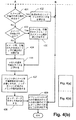
このとき、図4Aおよび図4Bを参照して、図3Aに示すような、オブジェクトのサイズおよび複雑さを決定するためのステップ303のサブステップの流れ図を示す。この処理中に、レンダ命令生成部109がオブジェクトのためのデータの部分を受信し、この部分は、オブジェクトのサイズおよび複雑さを決定するために十分である。ステップ302の後、処理が判断ブロック420へ進行し、現在のオブジェクトが文字であるかどうかの検査が行われる。これが文字であった場合、判断ブロック420がTRUE(YES)を返し、レンダ命令生成部が判断ブロック421へ進行する。判断ブロック421で、文字がすでにシステムにおいてフォント・メモリ104に格納されているかどうかの検査が行われる。判断ブロック421がTRUE(YES)を返した場合、レンダ命令生成部109がステップ422へ進行し、事前に計算された文字のサイズおよび複雑さが得られる。これが、判断ブロック304における後続の使用のために返される。次いで、レンダ命令生成部109がステップ429へ進行する。
【0042】
判断ブロック421がFALSE(NO)を返した場合、レンダ命令生成部109が判断ブロック423へ進行し、文字がビット・マップであるかどうかの検査が行われる。判断ブロック423がTRUE(YES)を返した場合、レンダ命令生成部109がステップ424へ進行し、ビット・マップのサイズ(幅および高さ)が読み取られるが、ビット・マップ・データ自体は読み取られない。ステップ424の後、レンダ命令生成部109がステップ425へ進行し、レンダ命令生成部109が、文字によって生成されたエッジ・データのサイズの最悪の推定値を計算し、これは、1つのチェッカーボード状の画素または類似するものを仮定することによって行われる。これは、現在のオブジェクトのサイズおよび複雑さとして、判断ブロック304における後続の使用のために返される。ステップ425の後、レンダ命令生成部109がステップ429へ進行する。
【0043】
判断ブロック423がFALSE(NO)を返し、すなわち文字がビット・マップでなかった場合、レンダ命令生成部109がステップ427へ進行する。
【0044】
判断ブロック420がFALSE(NO)を返し、すなわちオブジェクトが文字でなかった場合、レンダ命令生成部109が判断ブロック426へ進行し、現在のオブジェクトが経路データによって定義された形状であるかどうかの検査が行われる。判断ブロック426がTRUE(YES)を返した場合、レンダ命令生成部がステップ427へ進行する。
【0045】
ステップ427中に、レンダ命令生成部109が形状または文字のための経路データを読み取る。別法として、レンダ命令生成部109が経路データの読み取りを延期し、経路データのためのヘッダ内から、形状または文字のサイズおよび複雑さを決定するために十分な情報を検索することができる。これは、好ましい実施形態では実施されていない。これは、大抵の既存のページ記述言語がこの種類のヘッダ情報を含まないからである。ステップ427の後、レンダ命令生成部109がステップ428へ進行し、経路によって生成されるエッジ・データのサイズの最悪の推定値を、経路における点の数および経路の境界ボックスを使用して計算する。これは、現在のオブジェクトのサイズおよび複雑さの一態様として、判断ブロック304における後続の使用のために返される。ステップ428の後、レンダ命令生成部109がステップ429へ進行する。
【0046】
判断ブロック426がFALSE(NO)を返した場合、レンダ命令生成部がステップ430へ進行する。現在のオブジェクトが文字または形状でなかった場合、これはイメージでなければならない。ステップ430中に、レンダ命令生成部109がイメージのためのヘッダを読み取り、これがイメージ・データのサイズ(幅および高さ)、および各画素のサイズを定義する(ステップ430)。ヘッダは、イメージに適用される変換も含む。ステップ430の後、次いで、レンダ命令生成部109が判断ブロック431へ進行する。
【0047】
判断ブロック431で、イメージが圧縮されずに、待ち行列およびレンダ・エンジンにおいてイメージのために可能にされた最大メモリ内に適合するかどうかの検査が行われる。判断ブロック431がTRUE(YES)を返した場合、レンダ命令生成部109が、イメージの4つの隅の点をすべてイメージ変換によって変換することによって生成されるエッジ・データの量を計算する。ステップ432の後、レンダ命令生成部がステップ429へ進行する。
【0048】
判断ブロック431がFALSE(NO)を返した場合、レンダ命令生成部109が判断ブロック433へ進行し、イメージが回転されるかどうかの検査が行われる。
【0049】
イメージが回転されないか、あるいは、小さい角度のみ回転される場合、判断ブロック433がFALSE(NO)を返し、レンダ命令生成部がステップ434へ進行する。ステップ434中に、レンダ命令生成部109がリソースを計算し、イメージが水平圧縮されたストリップに分割されることを知る。ステップ434の後、レンダ命令生成部109がステップ436へ進行する。
【0050】
他方では、イメージが大幅な角度で回転される場合、判断ブロック433がTRUE(YES)を返し、レンダ命令生成部109がステップ435へ進行する。ステップ435で、レンダ命令生成部109がリソースを計算し、イメージがタイル化圧縮されたフラグメントに分割されることを知る。ステップ435の後、レンダ命令生成部109がステップ436へ進行する。
【0051】
ステップ436中に、レンダ命令生成部109が、イメージの総圧縮データが占有することができる、メモリの最大可能サイズを計算する。これは、現在のオブジェクトのサイズおよび複雑さの1つの特性として、判断ブロック304における後続の使用のために返される。ステップ436の後、レンダ命令生成部がステップ437へ進行し、レンダ・エンジン105において、バッファがイメージ・データを圧縮解除するために必要とされるメモリの量を計算する。これは、現在のオブジェクトのサイズおよび複雑さのもう1つの特性として、判断ブロック304における後続の使用のために返される。ステップ437の後、レンダ命令生成部109がステップ438へ進行し、水平ストリップまたはタイル化フラグメントのエッジ・データに必要とされる、メモリにおける空間を計算する。これは、現在のオブジェクトのサイズおよび複雑さのさらなる特性として、判断ブロック304における後続の使用のために返される。ステップ438の後、レンダ命令生成部109がステップ429へ進行する。
【0052】
ステップ429中に、レンダ命令生成部109は、現在のオブジェクトが、好ましい実施形態ではレベルおよび/または色スロットであるいずれかの複雑さのリソースを、現在のレンダ命令におけるいずれかの以前のオブジェクトと共有できるかどうかを、その範囲および充填色に基づいて決定する。オブジェクトがレベルまたは充填色を以前のオブジェクトと共有できない場合、新しいレベルを、それが追加されたときにそれに割り振らなければならない。これらは、現レンダ命令セットに、レンダ・エンジン105の制限をオーバーフローさせる可能性がある。また、オブジェクトがある量のメモリをレンダ命令待ち行列およびレンダ・エンジンにおいて使い果たし、これは、レンダおよびシステム・リソースを、そのエッジの生成および追跡において使い果たす。オブジェクトを追加することによっても、これらの制限をオーバーフローする可能性がある。これらのすべての制限に加えて、システムまたはレンダ・エンジンのいずれかに存在する他のいかなる制限も、ステップ303で決定されたオブジェクトのサイズおよび複雑さと共に、図3Aのステップ304で検査される。
【0053】
このとき、図5Aおよび図5Bを参照して、図3Bに示すような、現在のオブジェクトのデータの残りを受信するステップ312のサブステップの流れ図を示す。この副処理はステップ310で開始し、判断ブロック540へ進行し、現在のオブジェクトが文字かどうかの検査が行われる。判断ブロック540がTRUE(YES)を返した場合、レンダ命令生成部109が判断ブロック541へ進行し、なお受信するビット・マップ・イメージ・データがあるかどうかの検査が行われる。
【0054】
判断ブロック541がTRUE(YES)を返した場合、レンダ命令生成部109がステップ542へ進行し、ビット・マップ・データが受信される。ステップ542の後、レンダ命令生成部がステップ543へ進行し、ビット・マップ・イメージを追跡してエッジ・データを生成する。次いで、544で、このエッジ・データがフォント・キャッシュ104に、このオブジェクトの文字定義を文字キーとして使用して格納される。このエッジ・データも、現レンダ命令セットの一部を形成する。
【0055】
判断ブロック541がFALSE(NO)を返した場合、レンダ命令生成部109が判断ブロック545へ進行し、なおエッジへ変換する経路データがあるかどうかの検査が行われる。なお経路データがあった場合、判断ブロック545がTRUE(YES)を返し、レンダ命令生成部109がステップ546へ進行し、経路データがエッジ・データに変換される。このエッジ・データも、現レンダ命令セットの一部を形成する。
【0056】
判断ブロック540がFALSE(NO)を返した場合、レンダ命令生成部109が判断ブロック547へ進行し、現在のオブジェクトが形状であるかどうかの検査が行われる。現在のオブジェクトが形状であった場合、判断ブロック547がTRUE(YES)を返し、レンダ命令生成部109がステップ546へ進行し、形状の経路データがエッジ・データに変換される。このエッジ・データも、現レンダ命令セットの一部を形成する。
【0057】
判断ブロック547がFALSE(NO)を返した場合、現在のオブジェクトがビットマップまたは形状ではなく、そのためイメージでなければならず、レンダ命令生成部109が判断ブロック548へ進行し、イメージを圧縮する必要があるかどうかが検査される。イメージを圧縮する必要がない場合、判断ブロック548がFALSE(NO)を返し、レンダ命令生成部109がステップ549へ進行する。ステップ549中に、レンダ命令生成部がイメージ・データを直接現レンダ命令セットに読み込む。次いで、レンダ命令生成部109がステップ550へ進行し、イメージのためのエッジを生成する。このエッジ・データも、現レンダ命令セットの一部を形成する。
【0058】
イメージが圧縮される場合、判断ブロック548がTRUE(YES)を返し、レンダ命令生成部がステップ551へ進行する。ステップ551中に、レンダ命令生成部109がイメージ・データの水平ストリップを読み取る。ステップ551の後、レンダ命令生成部109が判断ブロック552へ進行し、イメージが水平ストリップにおいてのみ圧縮されるかどうかの検査が行われる。判断ブロック552がTRUE(YES)を返した場合、レンダ命令生成部109がステップ553へ進行し、ストリップが圧縮される。
【0059】
判断ブロック552がFALSE(NO)を返した場合、レンダ命令生成部109がステップ554へ進行し、ストリップが垂直にタイル・フラグメントに分割される。ステップ554の後、命令生成部109がステップ555へ進行し、次いで、タイル・フラグメントが個別に圧縮される。
【0060】
ステップ553またはステップ555の後、レンダ命令生成部109が判断ブロック556へ進行し、圧縮する水平ストリップがそれ以上あるかどうかの検査が行われる。判断ブロック556がTRUE(YES)を返した場合、命令生成部がステップ551へ戻り、イメージ・データの次の水平ストリップが読み取られる。以前の水平ストリップを読み取るために使用されたものと同じバッファを、再使用することができる。
【0061】
レンダ命令生成部109が、イメージ・データの水平ストリップの読み取りおよび処理を、それ以上イメージ・データがなくなるまで継続する。次いで、判断ブロック556がFALSE(NO)を返し、レンダ命令生成部がステップ557に進む。ステップ557中に、レンダ命令生成部109がイメージにおけるすべてのストリップまたはフラグメントのためのエッジ・データを作成し、図3Bのステップ313の処理を継続する。
【0062】
レンダ・システムの制約により、イメージをデシメートならびに圧縮しなければならない可能性があることが可能である。レンダ・エンジン105により、イメージをわずかに2倍まで縮小できることが好ましい。したがって、入力イメージがプリンタの解像度の2倍以上であった場合、画素を入力イメージから除去してその解像度を低下させなければならない。好ましい実施形態では、これが、x方向における適切な数の画素を平均化し、y方向における走査線を省くことによって達成される。解像度の制限は、システム内で処理される、もう1つのリソース制限である。
【0063】
いくつかの状況では、圧縮されたイメージ・データが、可能にされた最大空間内に適合しない。これは、大抵のイメージ圧縮方式によって達成される圧縮率がデータ依存であり、所望の圧縮率を達成できないからである。また、イメージ全体を同じ方法において圧縮しなければならず、そうでないとアーチファクトが印刷ページにおいて可視となる。また、イメージ・データがページ記述から読み取られた後、これを再度読み取ることもできない。そのため、イメージの一部が圧縮され、圧縮されたデータが使用可能な空間に適合しないことが判明した場合、既存の圧縮データを圧縮解除し、再度圧縮して、より高い圧縮率を与えなければならない。これは、最初の場合よりも多くのリソースを使用せずに行われる。
【0064】
図6Aおよび図6Bを参照すると、同図は図1Aのレンダ命令ローダによって使用される、1つまたは複数のレンダリング命令セットをロードするための手順の流れ図を示している。レンダ命令ローダは継続的にループし、1つまたは複数のレンダ命令セットが待ち行列に現れるまで待機し、それらを一度に1セットずつ処理し、次いで再度待機する。
【0065】
レンダ命令ローダ110は、レンダ命令生成部109と同時に開始するが、それとは非同期的な方法で動作する。レンダ命令ローダがステップ600で開始し、ステップ660へ進行し、レンダ命令セットが命令待ち行列112上に存在するまで待機する。レンダ命令セットが現れたとき、ステップ661で、レンダ命令ローダ110が現命令セットを即時にレンダ・エンジンにロードする。レンダ命令ローダがステップ662へ進行し、現レンダ命令セットをデキューし、制御情報を現レンダ命令セットのヘッダから抽出し、命令待ち行列112において現レンダ命令セットによって使用された空間を解放する。
【0066】
ステップ662の後、レンダ命令ローダ110が判断ブロック663へ進行し、現レンダ命令セットが背景イメージを使用するかどうかの検査が行われる。すなわち、現命令セットが、背景イメージを描画するための命令を含むかどうかを検査する。判断ブロック663がTRUE(YES)を返した場合、レンダ命令ローダがステップ664へ進行し、背景イメージの参照カウンタが減分される。この参照カウンタは、上で論じたレンダ命令生成部109によって使用されたものと同じカウンタであり、ローダ110によっても生成部109によってもアクセスすることができる。
【0067】
ステップ664の後、レンダ命令ローダ110が判断ブロック665へ進行し、参照カウンタがゼロ(0)かどうかの検査が行われる。参照カウントがこのときゼロ(0)だった場合、これは、現在、待ち行列において、メモリにおいて現在の背景イメージと同じ空間を予約する他のレンダ命令セットがないことを意味し、そのため、メモリにおいて予約されたこの空間がもはや必要とされない。現在の背景イメージが、ステップ661中で、先にレンダ・エンジンにロードされたことに留意されたい。したがって、判断ブロック665がTRUE(YES)を返したとき、レンダ命令ローダ110が、予約された空間を解放し、判断ブロック667に進む。判断ブロック665がFALSE(NO)を返した場合、レンダ命令ローダが直接判断ブロック667へ進行する。参照カウンタの減分および検査は、非可分動作において行われなければならず、非同期的にレンダ命令セットを待ち行列に追加するレンダ命令生成部109との正確な動作を保証しなければならない。もう1つの実施では、レンダ・エンジンが命令を直接待ち行列から実行し、命令のデキューおよび参照カウントの減分が、レンダリングが完了した後に行われるようにすることが可能である。
【0068】
判断ブロック667で、現レンダ命令セットがレイヤ、すなわち、後続のレイヤのための背景イメージを生成するかどうかの検査が行われる。これは、現レンダ命令セットのヘッダに含まれた情報から決定することができ、これがレンダ命令生成部109によって追加される。判断ブロック667がFALSE(NO)を返した場合、レンダ命令ローダ110がステップ668へ進行し、レンダ・エンジン105の出力をプリンタ106に向けて送る。レンダ命令ローダ110がステップ669へ進行し、レンダ・エンジンを開始し、次いでステップ670へ進行し、現命令セットのレンダリングが終了するまで待機する。レンダリングが終了した後、レンダリング命令ローダがステップ660へ戻る。もう1つの実施形態では、レンダ命令ローダ110が、レンダ・エンジン105におけるメモリが使い尽くされるときのみ待機する。
【0069】
他方では、判断ブロック667が、現レンダ命令セットがレイヤを生成すると決定した場合、レンダ命令ローダ110がステップ671へ進行する。ステップ671中に、レンダ命令ローダ110が、次の命令セットが命令待ち行列112に来るまで待機する。次のレンダ命令セットが待ち行列において受信されたとき、レンダ命令ローダ110がステップ672へ進行する。ステップ672で、レンダ命令ローダ110が、メモリにおいて次のレンダ命令セットのための背景イメージの位置を得る。この段階で、レンダ命令ローダ110は次のレンダ命令セットをデキューしないが、ステップ673へ進行し、レンダ・エンジン105に、現レンダ命令セットのための画素データの出力をコンプレッサ111へ向けて送るように命令する。次いで、レンダ命令ローダ110がステップ674へ進行し、コンプレッサ111に、現レンダ命令セットの圧縮された画素データのためのその出力を、メモリにおいて次のレンダ命令セットのための背景イメージのために予約された空間に向けて送るように命令する。次いで、レンダ命令ローダ110がステップ675へ進行し、レンダ・エンジン105に、現命令セットのレンダリングを開始するように命令する。これはまた、コンプレッサ111に、結果として生じる出力画素データを圧縮するように命令し、次いで、これをメモリにおいて予約された空間に格納する。次いで、ステップ676で、レンダリング命令ローダが、レンダリングおよび圧縮が完了するまで待機する。次いで、レンダ命令ローダが判断ブロック677へ進行し、圧縮されたレンダ出力画素が、背景イメージのために使用可能な空間に適合したかどうかの検査が行われる。判断ブロック677がFALSE(NO)を返した場合、レンダ命令ローダ110がステップ678へ進行し、コンプレッサ111に、より高い圧縮率を達成するように指示する。ステップ678の後、レンダ命令ローダがステップ673へ戻る。他方では、判断ブロック677がTRUE(YES)を返し、すなわち、圧縮されたレンダ出力画素が、背景イメージのために使用可能な空間に適合した場合、レンダ命令ローダ110がステップ661に進む。
【0070】
レンダ・エンジン110を、いずれかの知られているレンダ・エンジンにいくらか変更を加えたものに基づかせることができる。レンダ・エンジンは、そのレンダリングされた画素データを、コンプレッサを介して命令待ち行列に戻すように送り直し、また、そのレンダリングされた画素データをプリンタへ向けて送る能力を有するべきである。コンプレッサを、いかなる知られているコンプレッサに基づかせることもできる。別法として、コンプレッサを省くこともでき、背景イメージが圧縮解除される結果となる。後者の状況では、これによりリソース制限がレンダリング・システム上に課せられる可能性がある。
【0071】
好ましいコンピュータ・システムは、次のオブジェクトが適合するかどうかについて、それを中間データに変換する前に検査する利点を有する。時として、次のオブジェクトが適合するかどうかについての検査が、オブジェクトのためのデータがシステム全体によって受信される前であっても行われる。たとえば、大きいイメージが到着しようとしている可能性がある。システムが、このイメージによりシステムにおけるいずれかの制限が越えられるかどうかの検査を、イメージのためのデータが受信される前に行う。より小さいオブジェクト、形状または文字などでは、データがシステムによって受信されるが、オブジェクトが適合するかどうかについての検査が行われるときに、中間データに変換されない。このように、好ましいコンピュータ・システムは、リソースを効率的に使用することも、大きいかあるいは複雑なオブジェクトを正確に処理することもできる。さらに、好ましいコンピュータ・システムは、レンダ・エンジン内で著しいリソース制限を有し、これがオブジェクトおよびレンダ命令の、サイズよりもむしろ複雑さに関係付けられる。好ましいコンピュータ・システムは、入力オブジェクトがいずれかのシステムまたはレンダ・リソース制限を越えさせるかどうかを検査する。これは、オブジェクトがいずれかの制限を破らせる可能性がある場合、階層化機構を後押しする。加えて、好ましいコンピュータ・システムは、オブジェクトが受信されたちょうどそのときよりも使用可能になる可能性のある最大可能なメモリの量の知識を有し、最大量のメモリを越えるときにのみ階層化を実行する。これは、システムに、より多くのページ記述データを受信できるまで、ページの印刷を待機させる副作用を有する可能性がある。加えて、好ましいコンピュータ・システムは、背景画素データの圧縮を使用して、これをメモリ内に適合させる。圧縮は、有損失または無損失にすることができる。有損失圧縮はなお、わずかにイメージの外観を劣化させる可能性があるが、外観は、画素データを劣化させるよりもよくなる。無損失圧縮は、最終的なイメージの外観の劣化をまったく引き起こさない。
【0072】
図7を参照すると、同図には図1Aのレンダ命令生成部によって使用される、1つまたは複数のレンダリング命令セットを生成するための代替手順のフローチャートが示されている。この代替手順が図3Aおよび図3Bの手順と異なるのは、代替手順が、1つの単一のzレイヤにおいて合成演算子を使用して共に結合された、多数のプリミティブ・オブジェクトを含む合成オブジェクトを処理できることである。つまり、合成されたプリミティブ・オブジェクトのグループが、ペインターズ・アルゴリズムのために、単一のzレイヤとみなされ、合成されたオブジェクトが、合成演算子、および/またはペインターズ・アルゴリズムと互換性のない構造を使用して結合される。したがって、合成されたプリミティブ・オブジェクトのグループが、階層化の視点から非可分的であるように扱われる。これは、合成されたオブジェクトのすべての構成要素が、オブジェクトを現レンダ命令セットに追加できるようになる前に、受信されなければならないという意味である。これにより、図3Aおよび図3Bを参照して先に記載したような、1つまたは複数のレンダリング命令セットを生成するための手順がわずかに変更され、これについては以下で明らかになるであろう。しかし、これらの両方の手順には共通のステップが多数あり、理解を容易にするため、これらのステップを同じ参照番号によって参照する。
【0073】
他方では、図3Aおよび図3Bを参照して記載した手順は、zレイヤにつきただ1つの単一のプリミティブ・オブジェクトしか処理できない。この手順がzレイヤにつきただ1つのプリミティブ・オブジェクトを必要とするので、プリミティブ・オブジェクトを受信し、オブジェクトをレンダ命令待ち行列に「ペイント」する動作(ステップ314)を、順次動作にすることができる。これは、オブジェクト・データを、レンダ命令に変換する前に格納する必要がないという意味である。しかし、代替手順では、zレイヤにつき多数のプリミティブ・オブジェクトを処理することができる。そのため、オブジェクト・データおよび関連付けられた合成演算を、それらが受信されるときに格納する必要がある。zレイヤに寄与するすべてのプリミティブ・オブジェクトが受信されたとき、次いで、これらが現在のレンダ命令セットに、一度にまとめて「ペイント」される(ステップ314)。
【0074】
図7に戻り、1つまたは複数のレンダリング命令セットを生成するための代替手順を、以下でより詳細に記載する。レンダ命令生成部109が700で開始され、各単一の印刷ページについて初期化される。次いで702で、代替手順が、ページ記述の次のコマンドを、ページ記述言語(たとえば、PostScript(商標))に従って処理する。次いで704で、代替手順が、コマンドがいくつかのタイプの1つであるかどうかを検査し、次いで代替手順が、コマンド・タイプに応じて、4つの異なる副手順706、708、710および712のいずれか1つへ進行する。スイッチ・タイプのステートメントが、フロー制御においてこの多数の分岐を実行することができる。
【0075】
副手順706は、コマンド・タイプがプリミティブ・オブジェクトを追加するためのものであるときに活動化される。以下で明らかになるように、任意の数のプリミティブ・オブジェクトを受信し、構築中の合成オブジェクトに追加することができる。副手順708は、コマンド・タイプが合成演算子を変更するためのものであるときに活動化される。再度、任意の数のプリミティブ合成演算子を、合成オブジェクトを構築するために設定することができる。副手順710は、合成オブジェクトの構築が完了したときに活動化される。この副手順710は、zレイヤ内のコマンドがペインターズ・アルゴリズムと互換性がないときに、コマンド・タイプ上で活動化させることができる。副手順712は、コマンド・タイプが、他のユーティリティが活動化されるためのものであるときに、活動化される。このようなユーティリティには、クリッピング、診断、レンダ・モード調整などが含まれる可能性がある。
【0076】
これらの4つの副手順が、714を介してステップ702へ戻り、702でページ記述の次のコマンドが処理される。代替手順がステップ716で、ペイント副手順710が最終的に完了した後に終了する。
【0077】
図8Aおよび図8Bを参照すると、同図には図7に示す手順で使用される、プリミティブ・オブジェクトを追加するための副手順706をより詳細に記載されている。プリミティブ・オブジェクトを追加するための副手順706がステップ800で開始し、プリミティブ・オブジェクトに関する基本情報が検索される。副手順706が判断ブロック806へ進行し、現在のプリミティブ・オブジェクトで既存のオブジェクトを置換するかどうかの検査が行われる。判断ブロック806がTRUE(YES)を返した場合、808で、プリミティブ・オブジェクトが合成オブジェクト内で置換される。たとえば、合成オブジェクトが、ROP4演算子を使用するようにすることができる。これは、Source、PatternおよびMaskのオペランドを取る。Source、PatternまたはMaskは、ペイントされる最終的な結合が分かる前に数回置換することができる。プリミティブ・オブジェクトが置換中である場合、これが除去され(808)、これは、もはやこれが合成オブジェクトのための累積リソースに寄与しないからである。次に、ステップ302で、副手順706が、現レンダ命令セットによって利用された、すべてのレンダおよびシステム・リソースの現在の使用率を、図3Aおよび図3Bを参照して記載したものと類似の様式で得る。次いで、副手順706がステップ303へ進行し、ページ記述における次のプリミティブ・オブジェクトについての十分な情報を検索し、プリミティブ・オブジェクトの複雑さおよびサイズを決定する。これが決定される方法は、図4Aおよび図4Bの好ましい手順を参照して記載した方法に類似している。
【0078】
次に、判断ブロック810で、このプリミティブ・オブジェクトを追加することによりホスト・メモリ制限を使い尽くすかどうかの検査が行われる。ホスト・メモリ制限が使い尽くされない場合、副手順706がステップ816へ進行する。ホスト・メモリ制限を越える場合、判断ブロック812で、副手順706が、階層化が支援する可能性があるかどうかを検査する。階層化は、すでにオブジェクトが現レンダ命令セットに存在する場合、支援する可能性があり、これは、背景レイヤにレンダリングされたときに、ホスト・メモリを解放する。階層化がメモリを解放しない場合、副手順706が、「オブジェクトが複雑すぎる」というエラー814信号を返す。他方では、階層化が支援する可能性がある場合、副手順706がステップ305から310(図8A及び図8B)へ進行する。これらのステップ305から310(図8A及び図8B)の動作は、図3Aおよび図3Bのステップ305から310を参照して上で記載したものと実質的に同じであるので、その説明は省略する。
【0079】
ステップ310(図8B)の後、あるいは、判断ブロック810(図8A)がFALSE(NO)を返したとき、副手順706がステップ816へ進行し、プリミティブ・オブジェクトのデータの残りが受信される。この代替手順では、このステップが失敗する可能性があることに留意されたい。プリミティブ・オブジェクトを受信するには不十分なホスト・メモリがある可能性がある。不十分なホスト・メモリがある場合、レンダ命令待ち行列が完全に空になるまで待機した後であっても、この実施形態が「オブジェクトが複雑すぎる」というエラーを返す。不十分なホスト・メモリがあった場合、818で、プリミティブ・オブジェクトが、その複雑さの情報、現在の合成演算子および他のいかなる関連情報と共に保存される。次いで、副手順706が820で終了し、714を介して、次のコマンドのためにステップ702へ戻る。
【0080】
このとき、図9を参照して、図7に示す手順で使用される、合成演算子を変更するための副手順708の流れ図を示す。副手順708がステップ900で開始し、合成演算子が検索される。検索される合成演算子のタイプは、ステップ702で処理されたコマンドのタイプによって決まる。次いで、この合成演算子が現在の合成演算子として保存される。次いで、副手順708が904で終了し、714を介して、次のコマンドのためにステップ702へ戻る。
【0081】
図10Aおよび図10Bを参照すると、これらには図7に示す手順で使用される、ペイントするための副手順710の流れ図が示されている。この副手順710は、ステップ702で処理されたコマンドがペインターズ・アルゴリズムと互換性があるときに開始する。これが起こったとき、先に副手順706および708によって受信かつ格納された、現在構築中のプリミティブ・オブジェクトのグループが完了する。1002で、副手順710が最初に、構築されたプリミティブ・オブジェクトのグループのサイズおよび複雑さを決定する。これは、プリミティブ・オブジェクトの各構成要素の、知られているサイズおよび複雑さの合計に、場合によってはいくらかの追加リソース使用率を加えたものである。たとえば、ある実施では、プリミティブ・オブジェクトを共に合成するために追加のレベルが必要となる可能性がある。次いで、副手順710が、すべてのリソースの現在の使用率を、ステップ302(図3A)に類似した様式で決定する。次いで、副手順が判断ブロック304へ進行し、リソース制限を越えるかどうかの検査が、判断ブロック304(図3A)に類似した様式で行われる。判断ブロック304がFALSE(NO)を返した場合、副手順がステップ313へ進行する。他方では、判断ブロック304がTRUE(YES)を返した場合、副手順が判断ブロック1004へ進行し、階層化が支援する可能性があるかどうかの検査が行われる。判断ブロック1004が、階層化が支援しないと決定した場合、副手順が「オブジェクトが複雑すぎる」というエラー信号1006を返す。判断ブロック1004が、階層化が支援する可能性があると決定した場合、副手順710がステップ305から310(図10B)へ進行する。これらのステップ305から310(図10B)の動作は、図3Aおよび図3Bのステップ305から310を参照して上に記載したものと実質的に同じであり、以下でさらに記載しない。ステップ310の後、副手順710がステップ302へ進行する。
【0082】
判断ブロック304(図10A)がFALSEを返した場合、副手順がステップ313へ進行し、オブジェクト・データがレンダ命令に変換され、これはページ記述の中間データ形式であり、次いで314で、これらの変換されたレンダ命令を現レンダ命令セットに追加する。
【0083】
ステップ314の後、副手順710が判断ブロック315へ進行する。判断ブロック315で、現在のグループのプリミティブ・オブジェクトが、ページ上のプリミティブ・オブジェクトの最後のグループであるかどうかの検査が行われる。判断ブロック315がTRUE(YES)を返した場合、現レンダ命令セットが命令待ち行列112上で、レンダ命令ローダ110による後続のローディングのためにキューイングされる(ステップ316)。副手順710が317で終了し、次いで、代替手順が716で終了する。判断ブロック315がFALSE(NO)を返した場合、副手順710がステップ302へ戻り、次のグループのプリミティブ・オブジェクトを受信し、処理が次のグループのプリミティブ・オブジェクトについて再度開始する。
【0084】
このように、任意に複雑に構築されたオブジェクトをレンダリングすることができる。しかし、階層化は、z順序付けが適用されるところでしか行うことができない。そのため、合成オブジェクト全体がホスト・メモリに一度に適合しなければならず、これはまた、合成オブジェクトを固定メモリおよび固定リソース環境内でレンダリングできるようにするため、1つのレイヤ内に(メモリおよび複雑さに関して)適合しなければならない。実際は、従来のページ記述言語を使用する際に、オブジェクトが複雑すぎてレンダリングできないことは稀である。
【0085】
上述のように、命令待ち行列およびレンダ命令ローダを省くことができる。これらの場合、ただ1つのレンダリング命令セットしかなく、待ち行列の必要性がない。命令生成部が再度、受信されたオブジェクトが現レンダリング命令セットに追加された場合に使用可能なリソースを越えるかどうかを検査する。リソースを越える場合、命令生成部がレンダ・エンジンに、現セット(現在受信されたオブジェクトを含まない)を、メモリ(フレーム・ストア)において予約された背景イメージの空間上にレンダリングするように命令し、次いで、現在のレンダリストを空に設定する。しかし、この空の現レンダリング命令セットは、基本レンダ初期化命令を含む可能性がある。リソースを越えない場合、命令生成部は現レンダリング命令セットを変更しない。次いで、命令生成部が、受信されたオブジェクトを現レンダリング命令セットに追加する。受信されたオブジェクトがz順序における最後のオブジェクトであった場合、かつ、フレーム・ストア上にレンダリングされた場合、命令ローダがレンダ・エンジンに、現レンダリング命令セットをフレーム・ストアと組み合わせてレンダリングして、レンダリングされたページ記述を形成するように要求する。他方では、受信されたオブジェクトがz順序における最後のオブジェクトであった場合、かつ、フレーム・ストア上にレンダリングされなかった場合、命令ローダがレンダ・エンジンに、現セットをレンダリングして、レンダリングされたページ記述を形成するように要求する。
【0086】
前述の好ましい方法は、特定の制御フローを含む。好ましい方法の他の多数の変形形態があり、これらは本発明の精神または範囲から逸れることなく、異なる制御フローを使用する。さらに、好ましい方法の1つまたは複数のステップを、順次ではなく並列に実行することができる。前述の好ましい方法を、コンピュータ・プログラムとして実施することができ、これをコンピュータ可読媒体上に格納することができる。方法のステップを、ホスト・プロセッサにこれらのステップの機能を実行させるように命令するためのプログラム・コードとして実施することができる。
【0087】
<産業上の利用可能性>
上記から、本発明の実施形態がコンピュータ・グラフィックスおよび印刷産業に適用可能であることは明らかである。
【0088】
前記では、本発明のいくつかの実施形態のみを記載し、本発明の範囲および精神から逸れることなく修正および/または変更をこれに行うことができ、これらの実施形態は例示的であり制限的なものではない。たとえば、好ましい実施形態を、表示画面へのレンダリングにおける使用に適合させることができる。
【図面の簡単な説明】
【図1A】好適な実施形態を組み込む、ページ記述をレンダリングするためのコンピュータシステムの概略ブロック構成図である。
【図1B】好適な実施形態による、図1Aのコンピュータ・システムの機能的データフローを示すブロック図である。
【図1C】図1Aのコンピュータ・システムの動作を例示するための、例示的ページ記述のオブジェクトおよび対応する変換されたオブジェクトを示すブロック図である。
【図2A】好適な実施形態による、多数のページのキューイングの一例を例示するブロック図である。
【図2B】好適な実施形態による、多数のページのキューイングのもう1つの例を例示するブロック図である。
【図2C】時間におけるさらなる段階の、図2Bにおけるページのキューイングを例示するブロック図である。
【図3A】、
【図3B】図1Aのレンダ命令生成部によって使用される、1つまたは複数のレンダリング命令セットを生成するためのフローチャートである。
【図4A】、
【図4B】図3Aに示すような、オブジェクトのサイズおよび複雑さを決定するステップのサブステップのフローチャートである。
【図5A】、
【図5B】図3Bに示すような、現在のオブジェクトのデータの残りを受信するステップのサブステップのフローチャートである。
【図6A】、
【図6B】図1Aのレンダ命令ローダによって使用される、1つまたは複数のレンダリング命令セットをロードするためのフローチャートである。
【図7】図1Aのレンダ命令生成部によって使用される、1つまたは複数のレンダリング命令セットを生成するためのもう1つのフローチャートである。
【図8A】、
【図8B】図7に示す手順で使用される、プリミティブ・オブジェクトを追加するための副手順のフローチャートである。
【図9】図7に示す手順で使用される、合成演算子を変更するための副手順のフローチャートである。
【図10A】、
【図10B】図7に示す手順で使用される、ペイントするための副手順のフローチャートである。[0001]
BACKGROUND OF THE INVENTION
The present invention relates to a method and system for rendering a page description. The present invention also provides a computer program for rendering a page description.InAlso related.
[0002]
[Prior art]
In relatively recent years, there have been graphics packages for rendering printed pages to printers, display screens, and / or other locations (eg, files). Some of these graphics packages typically utilize a high level page description language to assist in the layout of printed pages. These graphics packages typically include a rendering system that converts a high level page description of the page layout into pixel data that can be used as raster data to be printed and / or displayed. .
[0003]
One such rendering system includes a full page frame store for holding images based on page or screen pixels. The full page frame store is a buffer and has space for every pixel that needs to be sent to the printer for the entire page. In these systems, any object received in the high level page description can be rendered immediately. The main problem with this system is that the memory required for the frame store is very large, especially where each pixel needs to be in continuous tone, which can have an associated transparency value. That is the case.
[0004]
[Problems to be solved by the invention]
There are existing rendering systems that perform more efficiently in both speed and memory usage when applied to a render list rather than applying objects sequentially in z-order. Such a system is very advantageous when the storage required for the render list is within available resources, but breaks when more resources are needed. For example, there is no limit on the size of the object render list, while the size of the frame store is large but limited and is strictly determined by the resolution and size of the printed page. When using such systems, they either fail when presented with a render list that exceeds available resources, or degrade to an object sequential immediate rendering method using a frame store.
[0005]
One object of the present invention is to substantially overcome or at least improve one or more disadvantages of existing configurations.
[0006]
[Means for Solving the Problems]
According to a first aspect of the present invention, a method for rendering a page description on a rendering system is provided. Here, the page description includes one or more objects, and the method includes sequentially receiving the objects in z-order from bottom to top, and generating one or more render instruction sets. This generating step determines, for each received object, whether the current received object exceeds the rendering system resources by adding the corresponding render instruction to the current render instruction set. Sub-steps and sub-steps to create a new render instruction set if resources are exceeded, sub-steps to add the render instruction to the new render instruction set and draw the current render instruction set as a background image, The render command to which the current received object corresponds A sub-step of executing a sub step of adding, if not exceeding resources, the render command objects current received corresponding currentRenderPerform sub-steps for performing sub-steps to be added to the instruction set, and one or more renderslifeRendering the instruction set as pixel data.
[0007]
According to a second aspect of the invention, a method for rendering a page description is provided. Here, the page description includes one or more objects, and the method includes sequentially receiving the objects in z-order from bottom to top, the method receiving for each received object If the added object is added to the current render list, check if the resource is exceeded, if so, render the current render list on the frame store, then empty the current render list Substeps to set and the received object is added to the current render list, the received object is in z-orderInIf it was the last object in the frame store, when rendered on the frame store, the current render list is combined with the frame store to form the rendered page description; otherwise, the current render Render the list and perform sub-steps to form the rendered page description.
[0008]
According to a third aspect of the present invention, a system for rendering a page description is provided. Here, the page description includes one or more objects, and the system includes means for sequentially receiving objects in z-order from bottom to top and means for generating one or more render instruction sets. And means for generating, for each received object, rendering by adding a render instruction corresponding to the current received object to the current render instruction set.in order toA means to determine whether to exceed system resources, a means to create a new render instruction set if resources are exceeded, and a background to the current render instruction set by adding render instructions to the new render instruction set if resources are exceeded Means to draw as an image, and if the resource is exceeded, means to add a render instruction corresponding to the current received object to the new render instruction set, and if not, the corresponding of the current received object Means to add render instructions to the current render instruction set and one or more renderslifeMeans for rendering the instruction set as pixel data.
[0009]
According to a fourth aspect of the invention, a system for rendering a page description is provided. Here, the page description includes one or more objects, and the system includes means for sequentially receiving objects in z-order from bottom to top, and for each received object, the received object is currently Means to check if the resource is exceeded when added to the current render list, and if so, render the current render list on the frame store and then set the current render list to empty; Means to add the received object to the current render list, and the received objectInThe last object in the frame store, when rendered on the frame store, means to render the current render list in combination with the frame store to form a rendered page description;InMeans for rendering the current render list to form a rendered page description if it is the last object in the frame store and has not been rendered on the frame store.
[0010]
According to a fifth aspect of the invention, a computer program for rendering a page descriptionTheprovide. Here, the page description includes one or more objects.The AndThis computer program isOn the computer,Receive objects sequentially from bottom to top in z-orderprocedureAnd generate one or more render instruction setsprocedureAnd to produce thisprocedureFor each received object, the current received object determines whether to exceed the rendering system resources by adding the corresponding render instruction to the current render instruction set.procedureAnd create a new render instruction set if resources are exceededprocedureIf the resource is exceeded, the render instruction is added to the new render instruction set and the current render instruction set is drawn as the background image.procedureAnd if the resource is exceeded, add the render instruction corresponding to the current received object to the new render instruction set.procedureIf the resource is not exceeded, the corresponding render command for the current received object is displayed.RenderAdd to instruction setprocedureAnd further renders one or more rendering instruction sets as pixel dataLet the procedure run.
[0011]
According to a sixth aspect of the invention, a computer program for rendering a page descriptionTheprovide. Here, the page description includes one or more objects.The AndThis computer program isOn the computer,Receive objects sequentially from bottom to top in z-orderprocedureAnd for each received object, check if the received object exceeds the resource if added to the current render list, and if so, render the current render list on the frame store And then set the current render list to emptyprocedureAnd add the received object to the current render listprocedureAnd the received objects are in z-orderInIf it is the last object in the frame store and rendered on the frame store, the current render list is combined with the frame store to form the rendered page descriptionprocedureAnd the received objects are in z-orderInIf this is the last object in the list that has not been rendered on the frame store, render the current render list to form the rendered page descriptionLet the procedure run.
[0012]
DETAILED DESCRIPTION OF THE INVENTION
Several preferred embodiments of the present invention will now be described with reference to the drawings.
[0013]
Where reference is made to steps and / or functions having the same reference number in any one or more of the accompanying drawings, these steps and / or functions are for purposes of this description, unless the contrary intention appears. Have the same function or operation.
[0014]
FIG. 1 illustrates a
[0015]
The hardware components of the
[0016]
In an alternative embodiment, the pixel data generated by the render
[0017]
The high level page description can be any known high level page description language, such as the POSTSCRIPT language, for describing the layout of a printed page in the form of objects arranged in z-order.
[0018]
Referring now to FIG. 1B, a block diagram illustrating the functional data flow of the computer system of FIG. 1A is shown.
[0019]
Referring to FIG. 1C, the figure shows an example page description object and corresponding transformed object to illustrate the operation of the computer system of FIG. 1A. The render
[0020]
Next, the render
[0021]
The render
[0022]
In this way, the preferred embodiment can create instructions for generating pages into a layered format. The object that first arrives at the page description is therefore the lowest in z-order, which is converted to an instruction and then rendered as a layer on the pixel. These pixels are used as the background image for the next layer. Complex pages, or pages that contain large objects, can be rendered on several layers of frame stores. Some low-order objects on the page that use significant resources can be rendered as images, which can be used as background images for higher-order objects on the page. This has the advantage that a background image object can utilize fewer resources than its corresponding number of objects. A page containing a large number of objects usually exceeds the system's resource limits and can be converted to a layer and thus not exceed the resource limits.
[0023]
FIG. 2A is a block diagram illustrating an example of multi-page queuing according to a preferred embodiment. In a preferred embodiment, multiple pages can be prepared and rendered separately by a mechanism for queuing and queuing space resource sharing. In the preferred embodiment, the
[0024]
One render instruction set is preferably fully prepared and then queued. FIG. 2A is an example of the appearance of the
[0025]
FIG. 2B is a block diagram illustrating another example of multi-page queuing according to a preferred embodiment. FIG. 2B is an example of the appearance of the
[0026]
FIG. 2C is a block diagram illustrating the queuing of pages in FIG. 2B at a further stage in time. In particular, it is an example of the appearance of the
[0027]
The space reserved for the background image in the
[0028]
The instruction queue implementation in the preferred embodiment uses a dynamic memory allocator, which operates on memory reserved for use by the background image. This dynamic memory allocator is thread safe, the render instruction generator can allocate memory therein, and the render instruction loader operating asynchronously can free the memory.
[0029]
In the preferred embodiment, the space reserved for background images in
[0030]
However, in some other embodiments, the instructions may need to be kept on the queue. For example, the instructions can be kept until it is found that the page has been printed without error. If there is a print or paper error, the instructions can be reloaded into the render engine and the page can be printed again. One way to render each page with the complete instruction set is to discard all layers except the last layer and keep the background image associated with the last layer. In this type of system, the reserved space for the background image can be shared within the page, but the background image for each page requires its own separate reserved space, which is This is because there may be valid data in many background images at the same time. Another possible way is to render the last layer as a background image for the page and simply keep the background image for this page. In general, this saves space, but time is wasted unless the compressor operates synchronously with the printer to accept data at the same rate as the printer. The image used for paper error recovery can then be generated without loss of system speed. It is still necessary to keep the background image for each layered page. An alternative mechanism is to keep all render instruction data for all layers of the page. The background image can then be shared between all pages. However, if the limit that caused the layer was the size of memory available for the render instruction queue, it must be freed to allow other jobs to be printed. A hybrid of all the above methods is possible. That is, a hybrid mechanism that minimizes the memory saved for paper error recovery but maximizes the throughput rate.
[0031]
3A and 3B show a flowchart of a procedure for generating one or more rendering instruction sets used by the render instruction generator of FIG. 1A. At 300, the render
[0032]
The render
[0033]
If
[0034]
On the other hand, if the decision block 340 is TRUE (YES), that is, if the limit is exceeded, the render
[0035]
After
[0036]
After
[0037]
Next, the render
[0038]
After
[0039]
After
[0040]
In a preferred embodiment, the object passed to the system can be a text character or shape or image. Characters and paths can be filled with uniform color, mixed color, image color data (sometimes tiled), or pattern color data (also sometimes tiled). You can also define clip areas using objects. The render
[0041]
4A and 4B, there is shown a flowchart of sub-steps of
[0042]
If
[0043]
If the
[0044]
If
[0045]
During
[0046]
If the
[0047]
At
[0048]
If
[0049]
If the image is not rotated or is rotated only a small angle,
[0050]
On the other hand, if the image is rotated by a significant angle,
[0051]
During
[0052]
During
[0053]
Now referring to FIGS. 5A and 5B, there is shown a flowchart of sub-steps of
[0054]
If the
[0055]
When the
[0056]
If
[0057]
If
[0058]
If the image is compressed,
[0059]
If
[0060]
After
[0061]
The render
[0062]
Due to render system constraints, it is possible that the image may have to be decimated and compressed. Preferably, the render
[0063]
In some situations, the compressed image data does not fit within the maximum space allowed. This is because the compression ratio achieved by most image compression schemes is data dependent and cannot achieve the desired compression ratio. Also, the entire image must be compressed in the same way, otherwise artifacts will be visible on the printed page. Nor can it be read again after the image data has been read from the page description. Therefore, if a portion of the image is compressed and it turns out that the compressed data does not fit into the available space, the existing compressed data must be decompressed and recompressed to give a higher compression ratio. Don't be. This is done without using more resources than in the first case.
[0064]
Referring to FIGS. 6A and 6B, there is shown a flowchart of a procedure for loading one or more rendering instruction sets used by the render instruction loader of FIG. 1A. The render instruction loader loops continuously, waiting until one or more render instruction sets appear in the queue, processing them one set at a time, and then waiting again.
[0065]
The render
[0066]
After
[0067]
After
[0068]
At
[0069]
On the other hand, if the
[0070]
The render
[0071]
The preferred computer system has the advantage of checking the next object for conformance before converting it to intermediate data. Sometimes, a check is made whether the next object is compatible, even before data for the object is received by the entire system. For example, a large image may be about to arrive. The system checks whether any limits in the system are exceeded by this image before data for the image is received. For smaller objects, shapes, or characters, the data is received by the system but is not converted to intermediate data when the object is checked for suitability. In this manner, the preferred computer system can use resources efficiently and can accurately handle large or complex objects. Furthermore, the preferred computer system has significant resource limitations within the render engine, which are related to the complexity rather than the size of objects and render instructions. The preferred computer system checks whether the input object causes any system or render resource limit to be exceeded. This boosts the layering mechanism if the object can break any of the restrictions. In addition, the preferred computer system has knowledge of the maximum possible amount of memory that may be available more than just when the object was received and is layered only when the maximum amount of memory is exceeded. Execute. This can have the side effect of causing the system to wait for a page to be printed until more page description data can be received. In addition, the preferred computer system uses compression of background pixel data to adapt it in memory. Compression can be lossy or lossless. Lossless compression can still slightly degrade the appearance of the image, but the appearance is better than degrading the pixel data. Lossless compression does not cause any degradation in the appearance of the final image.
[0072]
Referring to FIG. 7, there is shown a flowchart of an alternative procedure for generating one or more rendering instruction sets used by the render instruction generator of FIG. 1A. This alternative procedure differs from the procedure of FIGS. 3A and 3B in that the alternative procedure includes a composite object containing multiple primitive objects that are combined together using a composite operator in one single z-layer. It can be processed. That is, the group of synthesized primitive objects is considered as a single z-layer for the Painter's algorithm, and the synthesized object is compatible with the composition operator and / or Painter's algorithm. Not bonded using a structure. Therefore, a group of synthesized primitive objects is treated as non-separable from a hierarchical point of view. This means that all components of the synthesized object must be received before the object can be added to the current render instruction set. This slightly modifies the procedure for generating one or more rendering instruction sets as described above with reference to FIGS. 3A and 3B, which will become apparent below. . However, both of these procedures have many common steps and are referred to by the same reference numbers for ease of understanding.
[0073]
On the other hand, the procedure described with reference to FIGS. 3A and 3B can process only one single primitive object per z-layer. Since this procedure requires only one primitive object per z-layer, the operation of receiving a primitive object and “painting” the object into the render instruction queue (step 314) can be made sequential. . This means that the object data need not be stored before being converted into render instructions. However, in an alternative procedure, a large number of primitive objects can be processed per z layer. As such, object data and associated compositing operations need to be stored as they are received. When all primitive objects that contribute to the z layer have been received, they are then “painted” together into the current render instruction set (step 314).
[0074]
Returning to FIG. 7, an alternative procedure for generating one or more rendering instruction sets is described in more detail below. The render
[0075]
[0076]
These four sub-procedures return to step 702 via 714, where the next command in the page description is processed. The alternative procedure ends at
[0077]
Referring to FIGS. 8A and 8B, there is described in more detail a sub-procedure 706 for adding primitive objects used in the procedure shown in FIG. A sub-procedure 706 for adding a primitive object begins at
[0078]
Next, at
[0079]
After step 310 (FIG. 8B), or when decision block 810 (FIG. 8A) returns FALSE (NO),
[0080]
At this time, referring to FIG. 9, there is shown a flowchart of the
[0081]
Referring to FIGS. 10A and 10B, there is shown a flow chart of the sub-procedure 710 for painting used in the procedure shown in FIG. This
[0082]
If decision block 304 (FIG. 10A) returns FALSE, the subprocedure proceeds to step 313 where the object data is converted to a render instruction, which is the intermediate data format of the page description, and then at 314 these Add the converted render instruction to the current render instruction set.
[0083]
After
[0084]
In this way, an arbitrarily constructed object can be rendered. However, layering can only be done where z-ordering is applied. As a result, the entire composite object must fit into host memory at once, and this also allows the composite object to be rendered in a fixed memory and fixed resource environment (in memory and complex). Must conform). In fact, when using traditional page description languages, it is rare that an object is too complex to render.
[0085]
As mentioned above, the instruction queue and render instruction loader can be omitted. In these cases, there is only one rendering instruction set and there is no need for a queue. The instruction generator again checks whether the received object exceeds available resources when added to the current rendering instruction set. If the resource is exceeded, the command generator instructs the render engine to render the current set (not including the currently received object) onto the space of the background image reserved in memory (frame store). Then, set the current render list to empty. However, this empty current rendering instruction set may contain basic render initialization instructions. If the resource is not exceeded, the instruction generator does not change the current rendering instruction set. The command generator then adds the received object to the current rendering command set. If the received object is the last object in z-order and rendered on the frame store, the instruction loader will render the current rendering instruction set in combination with the frame store to the render engine. , Request to form a rendered page description. On the other hand, if the received object was the last object in z-order and was not rendered on the frame store, the instruction loader rendered the current set to the render engine and rendered Request to form a page description.
[0086]
The preferred method described above involves a specific control flow. There are many other variations of the preferred method, which use different control flows without departing from the spirit or scope of the present invention. Furthermore, one or more steps of the preferred method can be performed in parallel rather than sequentially. The preferred method described above can be implemented as a computer program, which can be stored on a computer readable medium. The method steps may be implemented as program code for instructing a host processor to perform the functions of these steps.
[0087]
<Industrial applicability>
From the above, it is apparent that embodiments of the present invention are applicable to the computer graphics and printing industries.
[0088]
The foregoing describes only some embodiments of the present invention and modifications and / or changes may be made thereto without departing from the scope and spirit of the present invention, which are exemplary and restrictive. Not something. For example, the preferred embodiment can be adapted for use in rendering to a display screen.
[Brief description of the drawings]
FIG. 1A is a schematic block diagram of a computer system for rendering a page description incorporating a preferred embodiment.
1B is a block diagram illustrating the functional data flow of the computer system of FIG. 1A, according to a preferred embodiment.
FIG. 1C is a block diagram illustrating an example page description object and corresponding transformed objects to illustrate the operation of the computer system of FIG. 1A.
FIG. 2A is a block diagram illustrating an example of multi-page queuing according to a preferred embodiment.
FIG. 2B is a block diagram illustrating another example of multi-page queuing, according to a preferred embodiment.
2C is a block diagram illustrating the queuing of pages in FIG. 2B at a further stage in time.
FIG. 3A
FIG. 3B is a flowchart for generating one or more rendering instruction sets used by the render instruction generator of FIG. 1A.
FIG. 4A
4B is a flowchart of sub-steps of determining the size and complexity of an object as shown in FIG. 3A.
FIG. 5A
5B is a flowchart of sub-steps of receiving the remainder of the current object's data as shown in FIG. 3B.
FIG. 6A
6B is a flow chart for loading one or more rendering instruction sets used by the render instruction loader of FIG. 1A.
FIG. 7 is another flowchart for generating one or more rendering instruction sets used by the render instruction generator of FIG. 1A.
FIG. 8A
FIG. 8B is a flowchart of a sub procedure for adding a primitive object used in the procedure shown in FIG. 7;
FIG. 9 is a flowchart of a sub procedure for changing a composition operator used in the procedure shown in FIG. 7;
FIG. 10A
10B is a flowchart of a sub procedure for painting used in the procedure shown in FIG. 7;
Claims (27)
(a)前記オブジェクトを下から上へのz順に順次受信するステップと、
(b)1つまたは複数のレンダ命令セットを生成するステップとを含み、前記生成するステップは、受信された各オブジェクトについて、
(ba)前記受信した現在のオブジェクトに対応するレンダ命令を、既に受信したオブジェクトのレンダリング待ちとなっているレンダ命令を格納している現レンダ命令セットに追加する際に、前記レンダリングシステムのリソースを越えるかどうかを決定するサブステップと、
(bb)前記リソースを越える場合、
(bba)前記リソースに空きを発生させるため、前記現レンダ命令セットにあるレンダ命令を、レンダリングエンジンに供給し、背景イメージとして描画させるサブステップと、
(bbb)前記描画された前記背景イメージへの参照する命令を、新しいレンダ命令セットに追加するサブステップと、
(bbc)前記受信した前記現在のオブジェクトに対応するレンダ命令を、前記新しいレンダ命令セットに追加するサブステップ
を実行するサブステップと、
(bc)前記リソースを越えない場合、
(bca)前記受信された現在のオブジェクトに対応するレンダ命令を、前記現レンダ命令セットに追加するサブステップ
を実行するサブステップとを有し、
(c)前記1つまたは複数のレンダ命令セットを、前記レンダリングエンジンを用いて、画素データとしてレンダリングするステップ
を備えることを特徴とする方法。A method of rendering a page description on a rendering system, the page description including one or more objects,
(a) receiving the objects sequentially from bottom to top in z-order;
(b) generating one or more render instruction sets, the generating step for each received object;
(ba) When adding a render instruction corresponding to the received current object to the current render instruction set storing a render instruction that is already waiting for rendering of the received object , resources of the rendering system are added. A substep to determine whether to exceed,
(bb) If the resource is exceeded,
(bba) a sub-step of supplying a rendering instruction in the current render instruction set to a rendering engine to render as a background image in order to generate a space in the resource;
(bbb) a sub-step of adding an instruction to reference the drawn background image to a new render instruction set;
(bbc) a sub-step of executing a sub-step of adding a render instruction corresponding to the received current object to the new render instruction set ;
(bc) If the resource is not exceeded,
(bca) a substep of executing a substep of adding a render instruction corresponding to the received current object to the current render instruction set;
(c) rendering the one or more render instruction sets as pixel data using the rendering engine .
前記現レンダ命令セットをキューイングし、前記現レンダ命令セットの前記レンダリングの前記画素データを、メモリにおいて前記背景イメージのために予約された空間に格納するように要求するサブステップと、
メモリにおける前記空間を、先に割り振られていなかった場合、前記背景イメージのために割り振るサブステップと
をさらに実行することを特徴とする請求項1に記載の方法。If the resource is exceeded,
Sub-queuing the current render instruction set and requesting that the pixel data of the rendering of the current render instruction set be stored in memory in a space reserved for the background image;
The method of claim 1, further comprising: sub-allocating the space in memory for the background image if it was not previously allocated.
前記現レンダ命令セットをキューイングするサブステップをさらに実行することを特徴とする請求項1に記載の方法。If the resource is not exceeded and the current received object was the last object in the z-order,
The method of claim 1, further comprising the step of queuing the current render instruction set.
前記現在の受信されたオブジェクトを、対応するレンダ命令に変換するサブステップをさらに含むことを特徴とする請求項1に記載の方法。The generating step includes
The method of claim 1, further comprising the step of converting the current received object into a corresponding render instruction.
(ca)前記現レンダ命令セットの実行によって出力される画素データが、メモリにおいて前記背景イメージのために予約された空間に格納されるかどうかを判別するサブステップと、
(cb)前記現レンダ命令セットの前記画素データが、前記メモリにおいて前記背景イメージのために予約された前記空間に格納される場合、
(cba)前記現レンダ命令セットを前記背景イメージとしてレンダリングするサブステップと、
(cbb)前記背景イメージを、前記メモリにおいて予約された前記空間に格納するサブステップとを実行するサブステップと、
(cc)前記現レンダ命令セットの前記画素データが、前記メモリにおいて前記背景イメージのために予約された前記空間に格納されていない場合、
(cd)現レンダ命令セットを出力デバイスへレンダリングするサブステップを実行するサブステップと
を備えることを特徴とする請求項1に記載の方法。The rendering step includes:
(ca) a sub-step of determining whether pixel data output by execution of the current render instruction set is stored in a space reserved for the background image in memory;
(cb) when the pixel data of the current render instruction set is stored in the space reserved for the background image in the memory;
(cba) a sub-step of rendering the current render instruction set as the background image;
(cbb) a substep of executing the substep of storing the background image in the space reserved in the memory;
(cc) if the pixel data of the current render instruction set is not stored in the space reserved for the background image in the memory;
The method of claim 1, comprising: (cd) a substep of executing a substep of rendering the current render instruction set to an output device.
前記背景イメージを、前記メモリにおいて予約された前記空間に格納する前に圧縮するサブステップをさらに実行することを特徴とする請求項6に記載の方法。The pixel data output by execution of the current render instruction set is stored in the space of the memory reserved for the background image;
The method of claim 6, further comprising the step of compressing the background image before storing it in the space reserved in the memory.
(a)レンダリング命令生成部が、前記オブジェクトを下から上へのz順に順次受信するステップを含み、前記受信された各オブジェクトについて、
(aa)前記レンダリング命令生成部が、前記受信されたオブジェクトを、現在のレンダリストに追加する際に、リソースを越えるかどうかを検査し、越える場合、前記現在のレンダリストをレンダリングエンジンに供給してフレーム・ストア上にレンダリングし、次いで前記現在のレンダリストを空に設定し、前記レンダリングエンジンを用いてレンダリングして得られたイメージの参照をレンダリングリストに追加するサブステップと、
(ab)前記レンダリング命令生成部が、前記受信されたオブジェクトを、現在のレンダリストに追加する際に、リソースを越えるかどうかを検査し、越えない場合、前記受信されたオブジェクトを前記現在のレンダリストに追加し、前記受信されたオブジェクトが前記z順における最後のオブジェクトであった場合、
(aba)前記フレーム・ストア上のレンダリング済みが存在する場合、前記現在のレンダリストを前記レンダリングエンジンに供給して前記フレーム・ストアと組み合わせてレンダリングして、レンダリングされたページを形成し、前記フレーム・ストア上にレンダリング済みがない場合、前記現在のレンダリストを前記レンダリングエンジンに供給してレンダリングして、前記レンダリングされたページを形成するサブステップと
を実行することを特徴とする方法。A method of rendering a page description, the page description including one or more objects,
(a) a rendering command generation unit sequentially receiving the objects in z-order from bottom to top, and for each received object,
(aa) When adding the received object to the current render list, the rendering command generation unit checks whether the resource is exceeded, and if so, supplies the current render list to the rendering engine. Rendering on the frame store, then setting the current render list to empty and adding to the render list a reference to the image obtained by rendering using the rendering engine ;
(ab) When the rendering command generation unit adds the received object to the current render list, the rendering command generation unit checks whether or not the resource is exceeded, and if not, the received object is set to the current render. If added to the list and the received object was the last object in the z-order,
(aba) if there is a render on the frame store , supply the current render list to the rendering engine to render in combination with the frame store to form a rendered page; If not already rendered on the store, the current render list is supplied to the rendering engine for rendering to perform the sub-step of forming the rendered page.
前記オブジェクトを下から上へのz順に順次受信する手段と、
1つまたは複数のレンダ命令セットを生成する生成手段とを備え、当該生成手段は、
(i)前記受信された各オブジェクトについて、前記受信された現在のオブジェクトの対応するレンダ命令を、既に受信したオブジェクトのレンダリング待ちになっているレンダ命令を格納している現レンダ命令セットに追加する際に、前記レンダリングするためのシステムのリソースを越えるかどうかを判別する手段と、
(ii)前記リソースを越える場合、前記リソースに空きを発生させるため、前記現レンダ命令セットにあるレンダ命令を、レンダリングエンジンに供給し、背景イメージとして描画させる手段と、
(iii)前記リソースを越える場合、前記描画された前記背景イメージへの参照する命令を、新しいレンダ命令セットに追加する手段と、
(iv)前記リソースを越える場合、前記受信した前記現在のオブジェクトに対応するレンダ命令を、前記新しいレンダ命令セットに追加する手段と、
(v)前記リソースを越えない場合、前記受信された現在のオブジェクトに対応するレンダ命令を、前記現レンダ命令セットに追加する手段と
(vi)前記1つまたは複数のレンダ命令セットを、前記レンダリングエンジンを用いて、画素データとしてレンダリングする手段と
を備えることを特徴とするシステム。A system for rendering a page description, the page description including one or more objects,
Means for sequentially receiving the objects in z-order from bottom to top;
Generating means for generating one or more render instruction sets, the generating means comprising:
(i) for each object received; add a corresponding render instructions of said received current object, the current render instruction set that contains the render instruction that is already rendered waiting object received when the means for determining whether more than a resource system for the rendering,
(ii) means for supplying a render instruction in the current render instruction set to a rendering engine and rendering it as a background image in order to generate a free space in the resource when exceeding the resource;
(iii) means for adding, to the new render instruction set, an instruction to refer to the rendered background image if the resource is exceeded;
(iv) means for adding a render instruction corresponding to the received current object to the new render instruction set if the resource is exceeded;
(v) means for adding a render instruction corresponding to the received current object to the current render instruction set if the resource is not exceeded;
(vi) A system comprising: means for rendering the one or more render instruction sets as pixel data using the rendering engine .
前記リソースを越える場合、前記現レンダ命令セットをキューイングし、前記現レンダ命令セットの前記レンダリングの前記画素データを、メモリにおいて前記背景イメージのために予約された空間に格納するように要求する手段をさらに備えることを特徴とする請求項14に記載のシステム。The generating means includes
Means for queuing the current render instruction set if the resource is exceeded and requesting that the pixel data of the rendering of the current render instruction set be stored in memory in a space reserved for the background image 15. The system of claim 14, further comprising:
前記リソースを越える場合、前記現レンダ命令セットをキューイングし、前記現レンダ命令セットの前記レンダリングの前記画素データを、メモリにおいて前記背景イメージのために予約された空間に格納するように要求する手段と、
メモリにおける前記空間を、前記リソースを越える場合、先に割り振られていなかった場合、前記背景イメージのために割り振る手段と
を更に備えることを特徴とする請求項14に記載のシステム。The generating means includes
Means for queuing the current render instruction set if the resource is exceeded and requesting that the pixel data of the rendering of the current render instruction set be stored in memory in a space reserved for the background image When,
15. The system of claim 14, further comprising means for allocating the space in memory for the background image if it has not been previously allocated when the resource is exceeded.
前記リソースを越えない場合、かつ、前記現在の受信されたオブジェクトが前記z順における最後のオブジェクトであった場合、前記現レンダ命令セットをキューイングする手段
を更に備えることを特徴とする請求項14に記載のシステム。The generating means includes
The method of claim 14, further comprising: queuing the current render instruction set if the resource is not exceeded and if the current received object is the last object in the z-order. The system described in.
前記現在の受信されたオブジェクトを、対応するレンダ命令に変換する手段をさらに備えることを特徴とする請求項14に記載のシステム。The generating means includes
The system of claim 14, further comprising means for converting the current received object into a corresponding render instruction.
前記現レンダ命令セットの実行によって出力される画素データが、メモリにおいて前記背景イメージのために予約された空間に格納されるかどうかを判別する手段と、
前記現レンダ命令セットの実行によって出力される前記画素データが、前記メモリにおいて前記背景イメージのために予約された前記空間に格納される場合、前記現レンダ命令セットを前記背景イメージとしてレンダリングする手段と、
前記レンダリングされた背景イメージを、前記メモリにおいて予約された前記空間に格納する手段と、
前記現レンダ命令セットの実行によって出力される前記画素データが、前記メモリにおいて前記背景イメージのために予約された前記空間に格納されない場合、前記現レンダ命令セットを出力デバイスへレンダリングする手段と
を備えることを特徴とする請求項14に記載のシステム。The rendering means is:
Means for determining whether pixel data output by execution of the current render instruction set is stored in a space reserved in the memory for the background image;
Means for rendering the current render instruction set as the background image when the pixel data output by execution of the current render instruction set is stored in the space reserved for the background image in the memory; ,
Means for storing the rendered background image in the space reserved in the memory;
Means for rendering the current render instruction set to an output device if the pixel data output by execution of the current render instruction set is not stored in the space reserved for the background image in the memory. The system according to claim 14.
前記現レンダ命令セットの前記画素データが、前記メモリにおいて前記背景イメージのために予約された前記空間に格納される場合、前記背景イメージを、前記メモリにおいて予約された前記空間に格納する前に圧縮する手段
をさらに備えることを特徴とする請求項19に記載のシステム。The rendering means is:
If the pixel data of the current render instruction set is stored in the space reserved for the background image in the memory, the background image is compressed before storing in the space reserved in the memory 20. The system of claim 19, further comprising:
前記オブジェクトを下から上へのz順に順次受信する手段と、
受信された各オブジェクトについて、前記受信されたオブジェクトを、現在のレンダリストに追加する際に、リソースを越えるかどうかを検査し、越える場合、前記現在のレンダリストをフレーム・ストア上にレンダリングし、次いで前記現在のレンダリストを空に設定し、レンダリングして得られたイメージの参照をレンダリストに追加する手段と、
前記受信されたオブジェクトを、現在のレンダリストに追加する際に、リソースを越えるかどうかを検査し、越えない場合、前記受信されたオブジェクトを前記現在のレンダリストに追加する手段と、
前記フレーム・ストア上のレンダリング済みが存在する場合、前記現在のレンダリストを前記フレーム・ストアと組み合わせてレンダリングして、レンダリングされたページを形成し、前記フレーム・ストア上にレンダリング済みがない場合、前記現在のレンダリストをレンダリングして、前記レンダリングされたページを形成する手段と
を備えることを特徴とするシステム。A system for rendering a page description, the page description including one or more objects,
Means for sequentially receiving the objects in z-order from bottom to top;
For each object that is received, the received object, when adding to the current render list, checks whether more than a resource, exceeds case, render the render list of the current on the frame store, Means for setting the current render list to empty and adding a rendered image reference to the render list ;
Means for checking whether a resource is exceeded when adding the received object to the current render list and, if not, adding the received object to the current render list;
Said if the pre-rendering on the frame store is present, said the current render list by rendering in combination with the frame store to form the rendered page, if there is no pre-rendered on the frame store, system characterized in that it comprises means for rendering the render list of the current, to form the rendered page.
コンピュータに、
(i)前記オブジェクトを下から上へのz順に順次受信する手順と、
(ii)1つまたは複数のレンダ命令セットを生成する手順とを含み、前記生成する手順は、
(ii-i)前記受信した現在のオブジェクトに対応するレンダ命令を、既に受信したオブジェクトのレンダリング待ちとなっているレンダ命令を格納している現レンダ命令セットに追加する際に、前記レンダリングシステムのリソースを越えるかどうかを決定する手順と、
(ii-ii)前記リソースを越える場合、前記リソースに空きを発生させるため、前記現レンダ命令セットにあるレンダ命令を、レンダリングエンジンに供給し、背景イメージとして描画させる手順と、
(ii-iii)前記リソースを越える場合、前記描画された前記背景イメージへの参照する命令を、新しいレンダ命令セットに追加する手順と、
(ii-iv)前記リソースを越える場合、前記受信した現在のオブジェクトに対応するレンダ命令を、前記新しいレンダ命令セットに追加する手順と、
(ii-v)前記リソースを越えない場合、前記受信された現在のオブジェクトに対応するレンダ命令を、前記現レンダ命令セットに追加する手順とを含み、さらに、
(iii)前記1つまたは複数のレンダリング命令セットを前記レンダリングエンジンを用いて画素データとしてレンダリングする手順
を実行させることを特徴とするコンピュータプログラム。A computer program for rendering a page description, the page description including one or more objects,
On the computer,
(i) a procedure for sequentially receiving the objects in z-order from bottom to top;
(ii) generating one or more render instruction sets, the generating procedure comprising:
(ii-i) When adding the render instruction corresponding to the received current object to the current render instruction set storing the render instruction that is already waiting to render the received object , A procedure for determining whether to cross resources,
(ii-ii) a procedure for supplying a render instruction in the current render instruction set to a rendering engine and rendering it as a background image in order to generate a free space in the resource when exceeding the resource;
(ii-iii) a procedure for adding a reference instruction to the rendered background image to a new render instruction set when the resource is exceeded;
(ii-iv) if exceeding the resource , adding a render instruction corresponding to the received current object to the new render instruction set ;
(ii-v) adding a render instruction corresponding to the received current object to the current render instruction set if the resource is not exceeded, and
(iii) A computer program for causing the one or more rendering instruction sets to be rendered as pixel data using the rendering engine .
コンピュータに、
前記オブジェクトを下から上へのz順に順次受信する手順と、
受信された各オブジェクトについて、前記受信されたオブジェクトを、現在のレンダリストに追加する際に、リソースを越えるかどうかを検査し、越える場合、前記現在のレンダリストをフレーム・ストア上にレンダリングし、次いで前記現在のレンダリストを空に設定し、レンダリングして得られたイメージの参照をレンダリングリストに追加する手順と、
前記受信された各オブジェクトについて、前記受信されたオブジェクトを、現在のレンダリストに追加する際に、リソースを越えるかどうかを検査し、越えない場合、受信されたオブジェクトを前記現在のレンダリストに追加する手順と、
前記受信されたオブジェクトが前記z順における最後のオブジェクトであり、前記フレーム・ストア上にレンダリング済みが存在する場合、前記現在のレンダリストを前記フレーム・ストアと組み合わせてレンダリングして、レンダリングされたページを形成する手順と、
前記受信されたオブジェクトが前記z順における前記最後のオブジェクトであり、前記フレーム・ストア上にレンダリング済みが無かった場合、前記現在のレンダリストをレンダリングして、前記レンダリングされたページを形成する手順
を実行させることを特徴とするコンピュータプログラム。A computer program for rendering a page description, the page description including one or more objects,
On the computer,
Sequentially receiving the objects in z-order from bottom to top;
For each received object , when adding the received object to the current render list, check if the resource is exceeded, and if so, render the current render list on the frame store; Then setting the current render list to empty and adding the rendered image reference to the render list ;
For each received object, when adding the received object to the current render list, check whether the resource is exceeded, and if not, add the received object to the current render list And the steps to
Is the last object the received object in the z order, if you rendered on the frame store is present, the render list of the currently rendering in combination with the frame store, rendered page The steps of forming
Is the last object the received object in the z order, if rendered was not on in the frame store, and rendering the render list of the current, the procedure for forming the rendered page A computer program that is executed.
Applications Claiming Priority (3)
| Application Number | Priority Date | Filing Date | Title |
|---|---|---|---|
| AUPQ9058 | 2000-07-28 | ||
| AU9058 | 2000-07-28 | ||
| AUPQ9058A AUPQ905800A0 (en) | 2000-07-28 | 2000-07-28 | Rendering page descriptions |
Publications (3)
| Publication Number | Publication Date |
|---|---|
| JP2002169668A JP2002169668A (en) | 2002-06-14 |
| JP2002169668A5 JP2002169668A5 (en) | 2008-09-04 |
| JP4817549B2 true JP4817549B2 (en) | 2011-11-16 |
Family
ID=3823116
Family Applications (1)
| Application Number | Title | Priority Date | Filing Date |
|---|---|---|---|
| JP2001229426A Expired - Fee Related JP4817549B2 (en) | 2000-07-28 | 2001-07-30 | Page description rendering method and system |
Country Status (3)
| Country | Link |
|---|---|
| US (1) | US7084878B2 (en) |
| JP (1) | JP4817549B2 (en) |
| AU (1) | AUPQ905800A0 (en) |
Cited By (1)
| Publication number | Priority date | Publication date | Assignee | Title |
|---|---|---|---|---|
| KR101476418B1 (en) * | 2013-08-28 | 2014-12-24 | 가부시키가이샤 디에누에 | Image processing device and image processing program |
Families Citing this family (15)
| Publication number | Priority date | Publication date | Assignee | Title |
|---|---|---|---|---|
| AU2003208477A1 (en) | 2002-03-01 | 2003-09-16 | T5 Labs Ltd | Centralised interactive graphical application server |
| DE10217857C1 (en) * | 2002-04-22 | 2003-10-02 | Oce Printing Systems Gmbh | Printed data accessing method uses estimated value for stored data object size for determining initial memory address |
| US20040119724A1 (en) * | 2002-12-20 | 2004-06-24 | Imagelinx International Ltd. | Digital prepress masking tools |
| AU2003903448A0 (en) * | 2003-06-26 | 2003-07-17 | Canon Kabushiki Kaisha | A method for tracking depths in a scanline based raster image processor |
| US7755629B2 (en) * | 2004-06-30 | 2010-07-13 | Canon Kabushiki Kaisha | Method of rendering graphic objects |
| US7586500B2 (en) * | 2004-09-24 | 2009-09-08 | Canon Kabushiki Kaisha | Dynamic render algorithm selection |
| KR100668326B1 (en) * | 2005-02-01 | 2007-01-12 | 삼성전자주식회사 | Method for rendering 3D Graphics data and apparatus therefore |
| AU2005201930B2 (en) * | 2005-05-06 | 2009-02-19 | Canon Kabushiki Kaisha | Simplification of alpha compositing in the presence of transfer functions |
| US7978196B2 (en) * | 2006-03-02 | 2011-07-12 | Canon Kabushiki Kaisha | Efficient rendering of page descriptions |
| TW201037530A (en) * | 2009-04-14 | 2010-10-16 | Acer Inc | Method for displaying a plugin frame in a web browser, computer readable medium, and computer program product |
| CA2806537C (en) * | 2010-07-29 | 2019-04-16 | Allegorithmic | Device and method for generating procedural images with a cache |
| AU2010249337A1 (en) * | 2010-12-13 | 2012-06-28 | Canon Kabushiki Kaisha | Predicting the times of future events in a multi-threaded RIP |
| JP2014002591A (en) | 2012-06-19 | 2014-01-09 | Canon Inc | Image processing apparatus, image processing method, and computer program |
| AU2013211451A1 (en) | 2013-07-30 | 2015-02-19 | Canon Kabushiki Kaisha | Method of processing graphics with limited memory |
| CN109799963B (en) * | 2019-01-24 | 2022-06-07 | 南京沁恒微电子股份有限公司 | Dot matrix instruction analysis method for micro printer |
Family Cites Families (12)
| Publication number | Priority date | Publication date | Assignee | Title |
|---|---|---|---|---|
| DE3729023C2 (en) * | 1986-08-29 | 1995-03-16 | Canon Kk | Imaging device |
| JP3030941B2 (en) * | 1991-07-19 | 2000-04-10 | ブラザー工業株式会社 | Printing equipment |
| DE69327888T2 (en) * | 1992-06-15 | 2000-08-17 | Canon Kk | Method and device for printing according to a graphic language |
| US5680521A (en) * | 1992-06-15 | 1997-10-21 | Canon Kabushiki Kaisha | Printing method and apparatus |
| US5708763A (en) | 1993-12-21 | 1998-01-13 | Lexmark International, Inc. | Tiling for bit map image |
| JPH0971013A (en) * | 1995-05-10 | 1997-03-18 | Canon Inc | Printing control device and memory-control method and printing control method and storage medium storing control program |
| US5880737A (en) * | 1995-08-04 | 1999-03-09 | Microsoft Corporation | Method and system for accessing texture data in environments with high latency in a graphics rendering system |
| JP3292976B2 (en) * | 1996-07-22 | 2002-06-17 | 株式会社日立製作所 | Multiprocessor drawing processor |
| US6269190B1 (en) * | 1996-09-24 | 2001-07-31 | Electronics For Imaging, Inc. | Computer system for processing images using a virtual frame buffer |
| JPH10147017A (en) * | 1996-11-18 | 1998-06-02 | Canon Inc | Printing device and data control method |
| US6330072B1 (en) * | 1997-03-21 | 2001-12-11 | Global Graphics Software Limited | Method and apparatus for combining and ordering objects from a plurality of color PDL files representing separations to a display list of the appropriate order |
| GB9915012D0 (en) | 1999-06-29 | 1999-08-25 | Koninkl Philips Electronics Nv | Z-buffering graphics system |
-
2000
- 2000-07-28 AU AUPQ9058A patent/AUPQ905800A0/en not_active Abandoned
-
2001
- 2001-07-17 US US09/905,947 patent/US7084878B2/en active Active
- 2001-07-30 JP JP2001229426A patent/JP4817549B2/en not_active Expired - Fee Related
Cited By (1)
| Publication number | Priority date | Publication date | Assignee | Title |
|---|---|---|---|---|
| KR101476418B1 (en) * | 2013-08-28 | 2014-12-24 | 가부시키가이샤 디에누에 | Image processing device and image processing program |
Also Published As
| Publication number | Publication date |
|---|---|
| US20020012132A1 (en) | 2002-01-31 |
| JP2002169668A (en) | 2002-06-14 |
| US7084878B2 (en) | 2006-08-01 |
| AUPQ905800A0 (en) | 2000-08-24 |
Similar Documents
| Publication | Publication Date | Title |
|---|---|---|
| JP4817549B2 (en) | Page description rendering method and system | |
| EP0798665B1 (en) | Fallback processing for page generation using memory reduction techniques | |
| US6466210B1 (en) | Blending image data using layers | |
| US8861014B2 (en) | Systems and methods for optimized printer throughput in a multi-core environment | |
| JP5956770B2 (en) | Tile-based graphics system and method of operating such a system | |
| US20100315431A1 (en) | Combining overlapping objects | |
| EP2172905B1 (en) | Image processing apparatus, image processing method, program therefor, and medium storing program | |
| JPH0971013A (en) | Printing control device and memory-control method and printing control method and storage medium storing control program | |
| US20100079783A1 (en) | Image processing apparatus, and computer-readable recording medium | |
| JP6385406B2 (en) | Image processing apparatus, image processing method, and program | |
| JPH09282470A (en) | Graphic processing system | |
| AU2013211450A1 (en) | Fixed memory rendering | |
| KR20080076933A (en) | Transparency printing | |
| US8373903B2 (en) | Efficient implementation of raster operations flow | |
| AU767211B2 (en) | Rendering page descriptions | |
| AU2003204832B2 (en) | Rendering Graphic Object Based Images | |
| JPH11191055A (en) | Printing system, data processing method therefor, and storage medium stored with computer-readable program | |
| AU2003203486A1 (en) | Rendering Page Descriptions | |
| GB2331824A (en) | Inheriting in page production for a page printer | |
| JP2006031160A (en) | Graphic object processing method | |
| AU2005202070A1 (en) | Rendering graphic object based images | |
| US20020109853A1 (en) | Generating images quickly in raster image processing | |
| Recker et al. | A GPU accelerated PDF transparency engine | |
| JPH11305962A (en) | Printing processor, data processing method therefor and medium for storing computer readable program | |
| JP2000298565A (en) | Method and device for controlling printing and storage medium storing program for executing the printing controlling method |
Legal Events
| Date | Code | Title | Description |
|---|---|---|---|
| A521 | Request for written amendment filed |
Free format text: JAPANESE INTERMEDIATE CODE: A523 Effective date: 20080722 |
|
| A621 | Written request for application examination |
Free format text: JAPANESE INTERMEDIATE CODE: A621 Effective date: 20080722 |
|
| A977 | Report on retrieval |
Free format text: JAPANESE INTERMEDIATE CODE: A971007 Effective date: 20100811 |
|
| A131 | Notification of reasons for refusal |
Free format text: JAPANESE INTERMEDIATE CODE: A131 Effective date: 20100813 |
|
| A521 | Request for written amendment filed |
Free format text: JAPANESE INTERMEDIATE CODE: A523 Effective date: 20101012 |
|
| A131 | Notification of reasons for refusal |
Free format text: JAPANESE INTERMEDIATE CODE: A131 Effective date: 20110408 |
|
| A521 | Request for written amendment filed |
Free format text: JAPANESE INTERMEDIATE CODE: A523 Effective date: 20110606 |
|
| TRDD | Decision of grant or rejection written | ||
| A01 | Written decision to grant a patent or to grant a registration (utility model) |
Free format text: JAPANESE INTERMEDIATE CODE: A01 Effective date: 20110826 |
|
| A01 | Written decision to grant a patent or to grant a registration (utility model) |
Free format text: JAPANESE INTERMEDIATE CODE: A01 |
|
| A61 | First payment of annual fees (during grant procedure) |
Free format text: JAPANESE INTERMEDIATE CODE: A61 Effective date: 20110830 |
|
| FPAY | Renewal fee payment (event date is renewal date of database) |
Free format text: PAYMENT UNTIL: 20140909 Year of fee payment: 3 |
|
| R151 | Written notification of patent or utility model registration |
Ref document number: 4817549 Country of ref document: JP Free format text: JAPANESE INTERMEDIATE CODE: R151 |
|
| FPAY | Renewal fee payment (event date is renewal date of database) |
Free format text: PAYMENT UNTIL: 20140909 Year of fee payment: 3 |
|
| LAPS | Cancellation because of no payment of annual fees |