JP4815701B2 - TV signal distribution equipment - Google Patents
TV signal distribution equipment Download PDFInfo
- Publication number
- JP4815701B2 JP4815701B2 JP2001196054A JP2001196054A JP4815701B2 JP 4815701 B2 JP4815701 B2 JP 4815701B2 JP 2001196054 A JP2001196054 A JP 2001196054A JP 2001196054 A JP2001196054 A JP 2001196054A JP 4815701 B2 JP4815701 B2 JP 4815701B2
- Authority
- JP
- Japan
- Prior art keywords
- signal
- power line
- power
- television
- channel
- Prior art date
- Legal status (The legal status is an assumption and is not a legal conclusion. Google has not performed a legal analysis and makes no representation as to the accuracy of the status listed.)
- Expired - Fee Related
Links
Images


Description
【0001】
【発明の属する技術分野】
本発明は、アンテナ出力端子のある部屋に配置され、電力線を通信媒体としてテレビ信号を各部屋に配信するTV信号配信装置と、アンテナ出力端子のない部屋に配置され、前記テレビ配信装置から配信されるテレビ信号を受信するTV信号受信装置とを有するテレビ信号配信システムに関するものである。
【0002】
【従来の技術】
従来、テレビを設置する場合、部屋に設置されたアンテナ出力端子とテレビの入力端子とを同軸ケーブルを用いて接続する。この設置方法にあっては、テレビの設置場所は暗黙のうちにテレビ用のアンテナ出力端子がある部屋に限定されてしまい、レイアウトの自由度を低くする。また、希望のレイアウトにするためには、長いケーブルを用いて部屋の中を走らせる必要があり、景観を損なわせる可能性がある上、レイアウト変更の度に接続のための手間が必要となる。
【0003】
また、景観を損なわずに各部屋でテレビを視聴できる環境を構築する方法としては、壁の内側に別途同軸ケーブルによる専用線の設置工事を行う方法と、信号伝送手段として無線を利用する方法がある。しかしながら、前者の方法はコストがかかり、後者は異なる部屋間や、金属製の壁、障害物が多い家屋などでは電波が遮蔽され、安定した受信ができないという不具合がある。
【0004】
さらに、テレビ信号を独自の伝送用信号に変換する手段を用いる場合、アンテナ出力端子には複数のテレビ信号が重畳してきているため、全ての信号を配信するためには非常に広い帯域が必要となる。したがって、テレビ信号の配信装置側で何も加工せずにそのまま全てのテレビ信号を配信するわけにはいかない。つまり、必要な信号のみを配信するための仕組みが必要となる。
【0005】
【発明が解決しようとする課題】
このように、従来のテレビ信号配信システムにあっては、テレビをアンテナ出力端子近く以外に設置することが困難であり、暗黙のうちにアンテナ出力端子のある部屋に設置せざるを得ないという問題点を有していた。また、専用線を設けずに他の伝送手段を用いて他の部屋に設置されたテレビにテレビ信号を配信するためには、アンテナ出力端子から受けたテレビ信号を単純にそのまま伝送用のデータに変換し配信するだけでは、相当広い帯域が必要となり実用的でないという問題点を有していた。
【0006】
このテレビ信号配信システムでは、テレビ用のアンテナ出力端子が無い部屋においても簡単にテレビを視聴できることが要求されている。
【0007】
本発明は、この要求を満たすため、テレビ用のアンテナ出力端子が無い部屋においても簡単にテレビを視聴できるテレビ信号配信装置を提供することを目的とする。
【0008】
【課題を解決するための手段】
上記の課題を解決するために本発明のテレビ信号配信装置は、アンテナ出力端子のある部屋に配置することができ、第1の表示手段にテレビ信号を出力することが可能な第1の電力線通信装置および第2の表示手段にテレビ信号を出力することが可能な第2の電力線通信装置と電力線通信を行うテレビ信号配信装置であって、第1の電力線通信装置と電力線を介して接続することが可能な第1の電源コネクタと、第2の電力線通信装置と接続することが可能な第2の電源コネクタと、第1の電力線通信装置から第1の電源コネクタを介して送られるチャンネル選択信号によって所望のチャンネルを選択する第1のチャンネル制御部と、第2の電力線通信装置から第2の電源コネクタを介して送られるチャンネル選択信号によって所望のチャンネルを選択する第2のチャンネル制御部と、第1のチャンネル制御部により選択されたチャンネルに対応するテレビ信号を電力線通信用信号に変換し、電力線通信用信号を第1の電力線通信装置に第1の電源コネクタを介して送信する第1の電力線モデム部と、第2のチャンネル制御部により選択されたチャンネルに対応するテレビ信号を電力線通信用信号に変換し、電力線通信用信号を第2の電力線通信装置に第2の電源コネクタを介して送信する第2の電力線モデム部と、電力線より第1の電源コネクタを介して供給される電力を、第1のチャンネル制御部、第2のチャンネル制御部、第1の電力線モデム部および第2の電力線モデム部に供給するとともに、第2の電源コネクタを介して第2の電力線通信装置および第2の表示手段に供給する単一の電源供給部とを有し、第1のチャンネル制御部、第2のチャンネル制御部、第1の電力線モデム部、第2の電力線モデム部および電源供給部を内蔵する構成を備えている。
【0009】
これにより、テレビ用のアンテナ出力端子が無い部屋においても簡単にテレビを視聴できるテレビ信号配信装置が得られる。
【0010】
本発明の請求項1に記載のテレビ信号配信装置は、アンテナ出力端子のある部屋に配置することができ、第1の表示手段にテレビ信号を出力することが可能な第1の電力線通信装置および第2の表示手段にテレビ信号を出力することが可能な第2の電力線通信装置と電力線通信を行うテレビ信号配信装置であって、第1の電力線通信装置と電力線を介して接続することが可能な第1の電源コネクタと、第2の電力線通信装置と接続することが可能な第2の電源コネクタと、第1の電力線通信装置から第1の電源コネクタを介して送られるチャンネル選択信号によって所望のチャンネルを選択する第1のチャンネル制御部と、第2の電力線通信装置から第2の電源コネクタを介して送られるチャンネル選択信号によって所望のチャンネルを選択する第2のチャンネル制御部と、第1のチャンネル制御部により選択されたチャンネルに対応するテレビ信号を電力線通信用信号に変換し、電力線通信用信号を第1の電力線通信装置に第1の電源コネクタを介して送信する第1の電力線モデム部と、第2のチャンネル制御部により選択されたチャンネルに対応するテレビ信号を電力線通信用信号に変換し、電力線通信用信号を第2の電力線通信装置に第2の電源コネクタを介して送信する第2の電力線モデム部と、電力線より第1の電源コネクタを介して供給される電力を、第1のチャンネル制御部、第2のチャンネル制御部、第1の電力線モデム部および第2の電力線モデム部に供給するとともに、第2の電源コネクタを介して第2の電力線通信装置および第2の表示手段に供給する単一の電源供給部とを有し、第1のチャンネル制御部、第2のチャンネル制御部、第1の電力線モデム部、第2の電力線モデム部および電源供給部を内蔵することとしたものである。
【0011】
この構成により、各部屋に設置された電力線を通信媒体とする双方向通信が可能であるので、双方向通信を用いて、電力線上に所望のテレビ信号のみが重畳されるようにすることができ、全テレビ信号を重畳させるのに比較して、信号伝送に必要な使用帯域と配信装置における処理負担とを飛躍的に低減することが可能になり、またテレビ信号を伝送する時間も短縮することができるという作用を有する。さらに、TV信号受信装置の設置は電力線が接続された電源コンセントの近くであればどこでもよく、従来においては問題であったテレビ設置時におけるレイアウトの自由度を高くすることが可能となり、特に複数台のテレビがある場合の自由度が高まるという作用を有する。
【0016】
請求項2に記載のテレビ信号配信装置は、請求項1に記載のテレビ信号配信装置において、電力供給部は、電力線通信用信号に対して高インピーダンスであることを特徴としたものである。
【0026】
以下、本発明の実施の形態について、図1〜図8を用いて説明する。
【0027】
(実施の形態1)
図1は本発明の実施の形態1によるテレビ信号配信システムを示すブロック図である。
【0028】
図1において、100はTV信号配信装置、200はTV信号受信装置、101は信号を分配する信号分配器、102はTV信号受信装置200から電力線を介して送られるチャンネル選択信号によって所望のチャンネルを選択すると共に対応するテレビ信号を供給するチャンネル制御部、103はチャンネル制御部102で選択されたテレビ信号を電力線通信用信号に変換すると共にその電力線通信用信号を送信要求のあったTV信号受信装置200に対して送信する配信側の電力線モデム部、201は所望のテレビ信号のチャンネルを選択すると共にテレビ信号再生装置に対しテレビ信号を供給する情報制御部、202は選択したチャンネルを示すチャンネル選択信号を電力線通信用信号に変換してTV信号配信装置100に送信すると共にTV信号配信装置100から送出される電力線通信用信号を元のテレビ信号に変換する受信側の電力線モデム部である。また、104、204は電力線と接続された電源コンセント、105、205はテレビジョン受像機等のテレビ信号再生装置、106はアンテナ出力端子、107は電力線、206は情報制御部201に対して選択するチャンネルを指示したり、音声レベルを指示したりするリモートコントローラ(リモコン)、RM1はアンテナ出力端子106の有る部屋、RM2はアンテナ出力端子のない部屋である。
【0029】
このように構成されたテレビ信号配信システムについて、その動作を説明する。
【0030】
まずTV信号配信装置100について説明する。信号分配器101は、アンテナ出力端子106から出力されるアナログテレビ信号をテレビの入力端子とチャンネル制御部102に分配する。信号分配器101から分配されることにより、テレビ信号再生装置105では、問題無くテレビを視聴することができる。チャンネル制御部102は、電力線モデム部103から伝達されるチャンネル選択信号の示すチャンネル選択番号を記憶し、信号分配器101より伝達されるテレビ信号から当該チャンネル信号のみを抽出し、電力線モデム部103に対してそのテレビ信号を出力する。電力線モデム部103は、チャンネル制御部102より出力されるテレビ信号を電力線通信用信号に変換し、電力線にこの信号を重畳する。逆に、電力線モデム部103は、TV信号受信装置200から電力線107を経由して送られる電力線通信用信号をチャンネル制御部102に伝達するチャンネル選択信号に変換する。
【0031】
次に、TV信号受信装置200について、その動作を説明する。電力線モデム部202は、TV信号配信装置100から電力線107を介して送信されてきた電力線通信用信号を元のテレビ信号へ変換することにより、通常のテレビ信号(テレビジョン受像機等のテレビ信号再生装置205で視聴できるテレビ信号)に変換する。情報制御部201は、ユーザが選択したチャンネル番号を記憶し、電力線モデム部202に伝達する。電力線モデム部202は、受信の際には、電力線107を介して送信されてきた電力線通信用信号を分離し復調することにより、通常のテレビ信号を情報制御部201に出力する。逆に送信の際には、情報制御部201より出力されるチャンネル選択信号を電力線通信用信号に変換し、電力線にこの信号を重畳する。
【0032】
さらに、図1のテレビ信号配信システムの動作を説明する。
【0033】
情報制御部201は、ユーザがリモートコントローラ206などを介して選択したチャンネル番号を識別し、当該番号を記憶する。電力線モデム部202は、情報制御部201からのチャンネル選択信号を電力線通信用信号に変換し、電力線107にその信号を送信する。電力線モデム部103は、電力線107上の信号から電力線通信用信号を分離し、それを復調することにより、チャンネル選択信号を得て、チャンネル制御部102にその信号の示すチャンネル選択番号を伝達する。チャンネル制御部102は、そのチャンネル選択番号を記憶し、アンテナ出力端子106から所望チャンネルのテレビ信号のみを抽出し、そのテレビ信号を電力線モデム部103に伝達する。電力線モデム部103は、そのテレビ信号を電力通信用信号に変換し、電力線107にその信号を重畳する。電力線モデム部202は、電力線107上の信号から電力線通信用信号を分離し、それを復調することにより、元のテレビ信号を得る。そして、そのテレビ信号を情報制御部201に伝達する。
【0034】
図2はチャンネル制御部102および情報制御部201の他の例を示す構成図である。なお、説明の都合上、図1と異なる部分だけでなくシステムの全体図を示している。
【0035】
図2において、102は図1におけるチャンネル制御部であり、108はTV信号受信装置200から電力線を介して送られるチャンネル選択信号によって所望のチャンネルを選択し所望のテレビ信号を得るチャンネル選択部、109は選択されたチャンネルのテレビ信号をディジタルテレビデータに変換し圧縮する配信側のデータ変換部である。チャンネル制御部102はチャンネル選択部108とデータ変換部109より構成される。また、201は図1における情報制御部であり、208は所望のテレビ信号のチャンネルを選択するチャンネル識別部、209は圧縮したディジタルテレビデータを解凍する受信側のデータ変換部である。情報制御部201はチャンネル識別部208とデータ変換部209より構成される。なお、チャンネル制御部102と情報制御部201の構成以外は図1と同様である。
【0036】
このように構成されたテレビ信号配信システムについて、その動作を説明する。
【0037】
まずTV信号配信装置100について説明する。信号分配器101は、アンテナ出力端子106から出力されるアナログテレビ信号をテレビの入力端子とチャンネル選択部108に分配する。チャンネル選択部108は、電力線モデム部103から伝達されるチャンネル選択信号の示すチャンネル選択番号を記憶し、信号分配器101より伝達されるテレビ信号から当該チャンネル信号のみを抽出し、データ変換部109に対してそのテレビ信号を出力する。データ変換部109は、チャンネル選択部108より伝達されるテレビ信号をディジタルテレビデータに変換し、MPEG方式などを利用して圧縮する。電力線モデム部103は、データ変換部109より出力される圧縮したディジタルテレビデータを電力線通信用信号に変換し、電力線にこの信号を重畳する。逆に、電力線モデム部103は、TV信号受信装置200から電力線107を経由して送られる電力線通信用信号をチャンネル選択部108に伝達するチャンネル選択信号に変換する。
【0038】
次に、TV信号受信装置200について、その動作を説明する。電力線モデム部202は、TV信号配信装置100から電力線107を介して送信されてきた電力線通信用信号を圧縮したディジタルテレビデータへ変換し、データ変換部209は、電力線モデム部202からの圧縮したディジタルテレビデータを解凍することにより、通常のテレビ信号(テレビジョン受像機等のテレビ信号再生装置205で視聴できるテレビ信号)に変換する。チャンネル識別部208は、ユーザが選択したチャンネル番号を記憶し、電力線モデム部202に伝達する。電力線モデム部202は、受信の際には、電力線107を介して送信されてきた電力線通信用信号を分離し復調することにより、圧縮したディジタルテレビデータを生成し、この圧縮したディジタルテレビデータをデータ変換部209に出力する。逆に送信の際には、チャンネル識別部208より出力されるチャンネル選択信号を電力線通信用信号に変換し、電力線107にこの信号を重畳する。
【0039】
さらに、図2のテレビ信号配信システムの動作を説明する。
【0040】
チャンネル識別部208は、ユーザがリモートコントローラ206などを介して選択したチャンネル番号を識別し、当該番号を記憶する。電力線モデム部202は、チャンネル識別部208からのチャンネル選択信号を電力線通信用信号に変換し、電力線107にそのデータを送信する。電力線モデム部103は、電力線107上の信号から電力線通信用信号を分離し、それを復調することにより、チャンネル選択信号を得て、チャンネル選択部108にその信号の示すチャンネル選択番号を伝達する。チャンネル選択部108は、そのチャンネル選択番号を記憶し、アンテナ出力端子106から所望チャンネルのテレビ信号のみを抽出し、そのテレビ信号をデータ変換部109に伝達する。データ変換部109は、そのテレビ信号をデジタルテレビデータに変換し、さらにMEPG方式などを利用することにより圧縮した後、電力線モデム部103に圧縮ディジタルテレビデータを伝達する。電力線モデム部103は、圧縮ディジタルテレビデータを電力通信用信号に変換し、電力線107にそのデータを送信する。電力線モデム部202は、電力線107上の信号から電力線通信用信号を分離し、それを復調することにより、圧縮されたディジタルテレビデータを得る。そして、その圧縮ディジタルテレビデータをデータ変換部209に伝達する。データ変換部209は、圧縮されたディジタルテレビデータをTV信号配信装置100で使用した圧縮方式と同一の手段を利用して解凍し、通常のテレビ信号に再変換する。
【0041】
図3はTV信号配信装置100の他の例を示す構成図である。
【0042】
図3において、102、103は図1と同様のチャンネル制御部、電力線モデム部であり、110は構成要素102、103が搭載されたテレビ信号配信ユニットである。図1の構成では、信号分配器101と、チャンネル制御部102と、電力線モデム部103とが各々単一のもので構成されているが、図3のように、チャンネル制御部102と、電力線モデム部103とを統合してこれらをユニット化し、当該ユニット(テレビ信号配信ユニット)を追加拡張できるようにTV信号配信装置100にスロット(収納部)を設け、TV信号受信装置200とテレビ信号配信ユニット110を1対1に対応させる。これにより、テレビジョン受像機等のテレビ信号再生装置205の台数が増えた場合にも柔軟に対応することが可能である。この場合、電力線107上で複数のテレビ信号(つまり複数の電力線通信用信号)を多重化させる方式としては、周波数分割多重、時分割多重、符号分割多重、直交周波数分割多重伝送方式のいずれでも構わない。
【0043】
また、本実施の形態においては、TV信号受信装置200からテレビジョン受像機やモニタなどのテレビ信号再生装置205にテレビ信号を伝達する際に、TV信号受信装置200で音声レベルを変更できるようにTV信号受信装置200を構成し、かつ音声レベルをリモートコントローラ206で操作できるようにする。これにより、テレビ操作におけるチャンネル切替えや音量変更などを単一のリモートコントローラ206で行うことが可能となり、ユーザの利便性が向上する。
【0044】
以上のように本実施の形態によれば、TV信号配信装置100は、TV信号受信装置200から電力線107を介して送られるチャンネル選択信号によって所望のチャンネルを選択するチャンネル制御部102と、送信要求のあったTV信号受信装置200に対してテレビ信号を電力線通信用信号に変換して送信する配信側の電力線モデム部103とを有し、TV信号受信装置200は、ユーザが所望するチャンネルに対応したチャンネル選択信号を生成すると共に受信側の電力線モデム部202で変換したテレビ信号をテレビ信号再生装置205に伝達する情報制御部201と、チャンネル選択信号を電力線通信用信号に変換してTV信号配信装置100に送信すると共にTV信号配信装置100から送出される電力線通信用信号を元のテレビ信号に変換する受信側の電力線モデム部202とを有することにより、各部屋に設置された電力線を通信媒体とする双方向通信が可能であるので、双方向通信を用いて、電力線上に所望のテレビ信号のみが重畳されるようにすることができ、全テレビ信号を重畳させるのに比較して、信号伝送に必要な使用帯域と配信装置における処理負担とを飛躍的に低減することが可能になり、またテレビ信号を伝送する時間も短縮することができる。さらに、TV信号受信装置201の設置は電力線107が接続された電源コンセント204の近くであればどこでもよく、従来においては問題であったテレビ設置時におけるレイアウトの自由度を高くすることが可能となり、特に複数台のテレビがある場合の自由度が高まる。
【0045】
(実施の形態2)
図4は、本発明の実施の形態2によるテレビ信号配信システムを構成するテレビ受信再生装置を示すブロック図である。本実施の形態は、図1のTV信号受信装置200をテレビジョン受像機やモニタなどのテレビ信号再生装置205に内蔵したものである。また、内蔵する際には、テレビ信号再生装置205への電源供給、電力線通信用信号の授受およびTV信号受信装置200への電源供給を1系統の電源ケーブルで行えるようにする。
【0046】
図4において、300はテレビ受信再生装置であり、テレビ受信再生装置300は、情報制御部301と、テレビ表示部302と、電力線モデム部303と、電源/通信用信号分離部304とを有する。
【0047】
このように構成されたテレビ受信再生装置300について、その動作を説明する。情報制御部301は、送信の際には、ユーザが選択したチャンネル番号を記憶し、電力線モデム部303に伝達する。逆に受信の際には、電力線モデム部303から伝達されるテレビ信号をテレビ表示部302に出力する。テレビ表示部302は、テレビ信号に従って映像および音声を出力する。電力線モデム部303は、受信の際には、電力線107に重畳された信号から所望の電力線通信用信号のみを分離して復調し、情報制御部301に伝達する。逆に送信の際には、情報制御部301より出力されるチャンネル選択信号を電力線通信用信号に変換し、電力線107にこの信号を重畳する。電源/通信用信号分離部304は、電力線107から電源供給用の商用電源周波数と電力線通信用信号の周波数とを分離抽出し、電源供給用の信号は整流して各部へ供給し、電力線通信用信号は電力線モデム部303に伝達する。
【0048】
以上のように本実施の形態によれば、テレビ信号再生装置としてのテレビ表示部302とTV信号受信装置200との間のテレビ信号授受用の端子間接続が不要となり、同軸ケーブルなどによる配線の手間とコストを省くことができる。電源コンセントにテレビ受信再生装置300の電源ケーブルを接続するだけでテレビの視聴が可能となるため、ユーザの利便性が向上し、景観を損なう危険性も解消させることができる。
【0049】
(実施の形態3)
図5は、本発明の実施の形態3によるテレビ信号配信システムを構成するテレビ配信再生装置を示すブロック図である。本実施の形態は、TV信号配信装置100をテレビジョン受像機やモニタなどのテレビ信号再生装置に内蔵したものである。この際、実施の形態2と同様、テレビ信号再生装置への電源供給、電力線通信用信号の授受およびTV信号配信装置への電源供給を1系統の電源ケーブルで行えるようにする。
【0050】
図5において、400はテレビ配信再生装置であり、テレビ配信再生装置400は、信号分配部401と、テレビ信号処理部402と、テレビ信号再生装置としての表示部403と、チャンネル制御部404と、電力線モデム部405と、電源/通信用信号分離部406とを有する。
【0051】
このように構成されたテレビ配信再生装置400について、その動作を説明する。
【0052】
信号分配部401は、アンテナ出力端子106から出力されるアナログテレビ信号をテレビ信号処理部402と、チャンネル制御部404とに分配する。テレビ信号処理部402は、TV信号配信装置100を内蔵したテレビ配信再生装置400において選択されたチャンネル番号に対応するテレビ信号を信号分配部401より伝達されるテレビ信号の中から抽出し、表示部403で表示できる信号に変換する。表示部403は、この変換された信号を受けてモニタに表示する。チャンネル制御部404は、電力線モデム部405から伝達されるチャンネル番号を記憶し、信号分配部401より伝達されるテレビ信号から当該チャンネル信号のみを抽出し、電力線モデム部405に対してそのテレビ信号を出力する。電力線モデム部405は、チャンネル制御部404より出力されるテレビ信号を電力線通信用信号に変換し、電力線にこの信号を重畳する。逆に、TV信号受信装置200から電力線107を経由して送られる電力線通信用信号をチャンネル制御部404に伝達するチャンネル選択信号に復調する。電源/通信用信号分離部406は、電力線107から電源供給用の商用電源周波数と電力線通信用信号の周波数とを分離抽出し、電源供給用の信号は整流して各部へ供給し、電力線通信用信号は電力線モデム部405に伝達する。
【0053】
以上のように本実施の形態によれば、部屋に設置されたアンテナ出力端子106に接続した同軸ケーブルをTV信号配信装置100のアンテナ入力端子に接続するだけで、テレビを視聴できる上、別に設置されたTV信号受信装置200に対するテレビ信号の配信が可能となる。このように、従来と同様の接続方法によって、テレビ信号配信システムに必要なネットワークが形成されるため、ユーザがシステムを意識する必要がない。
【0054】
(実施の形態4)
図6は、本発明の実施の形態4によるテレビ信号配信システムを構成するビデオデッキを示すブロック図である。本実施の形態において、図1のTV信号配信装置100をビデオデッキに内蔵する。この際、ビデオデッキにテレビ信号再生装置用の電源コンセントを設け、当該電源コンセントにテレビ信号再生装置用の電源ケーブルを接続する。
【0055】
図6において、500はビデオデッキであり、このビデオデッキ500は、信号分配部501と、チャンネル制御部502、504と、電力線モデム部503、505と、ビデオ信号処理部506と、電源コンセント507と、電源/通信用信号分離部508、電源供給部509とを備える。
【0056】
このように構成されたビデオデッキ500について、その動作を説明する。
【0057】
信号分配部501は、アンテナ出力端子106から出力されるアナログテレビ信号をチャンネル制御部502とチャンネル制御部504に分配する。チャンネル制御部502は、電力線モデム部503から伝達されるチャンネル番号を記憶し、信号分配部501より伝達されるテレビ信号から当該チャンネル番号に対応するテレビ信号のみを抽出し、電力線モデム部503に対して、そのテレビ信号を出力する。また、ビデオ信号処理部506から伝達されるビデオ信号としての画像信号および音声信号も同様に電力線モデム部503に伝達する。この際、チャンネル制御部502では同時に、テレビ信号とビデオ信号の切り替えも行う。チャンネル制御部504は、電力線モデム部505から伝達されるチャンネル選択信号の示すチャンネル選択番号を記憶し、信号分配部501より伝達されるテレビ信号から当該チャンネル番号に対応するテレビ信号のみを抽出し、そのテレビ信号を電力線モデム部503に伝達する。電力線モデム部503は、チャンネル制御部502より出力されるテレビもしくはビデオ信号を電力線通信用信号に変換し、電源コンセント507にこの信号を出力する。逆に、電力線モデム部503は、TV信号受信装置200側から電源ケーブルおよび電源コンセント507を経由して送られる電力線通信用信号に変換されたチャンネル番号をチャンネル制御部502に伝達する信号(つまりチャンネル選択信号)に変換する。電源コンセント507は、テレビ受信再生装置300に対して電力の供給と電力線通信用信号の授受を行うために設けられたものである。電源コンセント507には、TV信号受信装置の電源プラグが接続される。ビデオ信号処理部506は、ビデオカセットの内容を読み出し、チャンネル制御部502に伝達する。
【0058】
電力線モデム部505は、チャンネル制御部504より出力されるテレビ信号を電力線通信用信号に変換し、電源/通信用信号分離部508にこの信号を出力する。逆に、電力線モデム部505は、他のTV信号受信装置200(図1参照)から電力線107および電源/通信用信号分離部508を経由して送られる電力線通信用信号に変換されたチャンネル番号をチャンネル制御部504に伝達する信号(つまりチャンネル選択信号)に変換する。電源/通信用信号分離部508は、電力線107から電源供給用の商用電源周波数と電力線通信用信号の周波数とを分離抽出し、電源供給用の信号を電源供給部509に出力し、電力線通信用信号を電力線モデム部505に伝達する。電源供給部509は、ビデオデッキ500内部の各部に対して電力を供給する。また、電源コンセント507から見て高インピーダンスになるように構成される。この構成により、電源コンセント507から電力が供給されるTV信号受信装置の電源側が上記商用電源と切り離され、TV信号受信装置200とビデオデッキ500との間の伝送路が独立なものとなる。
【0059】
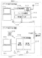
図7はビデオデッキ500と各装置等との接続例を示す接続図である。
【0060】
図7において、106は図6と同様のアンテナ出力端子、300はテレビ受信再生装置(図4参照)、104は電力線107(図1参照)に接続された電源コンセント、507は図6と同様の電源コンセントである。
【0061】
図7のように、テレビ受信再生装置300の電源ケーブルをビデオデッキ500に搭載された電源コンセント507に差しこめば、電源と通信の両方において接続されたことと同様になるため、テレビ受信再生装置300とビデオデッキ500との間の配線が不要になり、ユーザの配線する手間を省くことが可能となる。
【0062】
なお、本実施の形態ではTV信号配信装置100をビデオデッキ500に内蔵した例を示したが、同様にTV信号受信装置200(図1)を内蔵することも可能である。
【0063】
図8はアンテナ出力端子106の近くにテレビ信号再生装置を配置する必要のない場合の接続例を示す接続図である。
【0064】
図8において、100は図1と同様のTV信号配信装置、104は図1と同様の電源コンセント、200は図1と同様のTV信号受信装置、300は図4と同様のテレビ信号再生装置、204は図1と同様の電源コンセントである。図8に示すように、アンテナ出力端子106の近くにTV信号配信装置100のみを設置することも可能である。
【0065】
このように、TV信号配信装置100、TV信号受信装置200、テレビ受信再生装置300の相互間の接続形態としては種々の形態が考えられる。
【0066】
以上のように本実施の形態によれば、TV信号配信装置100またはTV信号受信装置200はビデオデッキ500に内蔵され、ビデオデッキ500は、1本の電源ケーブルに接続された電源コンセント507を有し、1本の電源ケーブルを介して電源供給および電力線からの信号の受信が可能であることにより、テレビ受信再生装置300は電源コンセント507を介して電源供給を受け、またビデオデッキ500から特別な配線無くテレビ信号を入力することができる。
【0067】
【発明の効果】
以上説明したように本発明の請求項1に記載のテレビ信号配信装置によれば、アンテナ出力端子のある部屋に配置することができ、第1の表示手段にテレビ信号を出力することが可能な第1の電力線通信装置および第2の表示手段にテレビ信号を出力することが可能な第2の電力線通信装置と電力線通信を行うテレビ信号配信装置であって、第1の電力線通信装置と電力線を介して接続することが可能な第1の電源コネクタと、第2の電力線通信装置と接続することが可能な第2の電源コネクタと、第1の電力線通信装置から第1の電源コネクタを介して送られるチャンネル選択信号によって所望のチャンネルを選択する第1のチャンネル制御部と、第2の電力線通信装置から第2の電源コネクタを介して送られるチャンネル選択信号によって所望のチャンネルを選択する第2のチャンネル制御部と、第1のチャンネル制御部により選択されたチャンネルに対応するテレビ信号を電力線通信用信号に変換し、電力線通信用信号を第1の電力線通信装置に第1の電源コネクタを介して送信する第1の電力線モデム部と、第2のチャンネル制御部により選択されたチャンネルに対応するテレビ信号を電力線通信用信号に変換し、電力線通信用信号を第2の電力線通信装置に第2の電源コネクタを介して送信する第2の電力線モデム部と、電力線より第1の電源コネクタを介して供給される電力を、第1のチャンネル制御部、第2のチャンネル制御部、第1の電力線モデム部および第2の電力線モデム部に供給するとともに、第2の電源コネクタを介して第2の電力線通信装置および第2の表示手段に供給する単一の電源供給部とを有し、第1のチャンネル制御部、第2のチャンネル制御部、第1の電力線モデム部、第2の電力線モデム部および電源供給部を内蔵することにより、各部屋に設置された電力線を通信媒体とする双方向通信が可能であるので、双方向通信を用いて、電力線上に所望のテレビ信号のみが重畳されるようにすることができ、全テレビ信号を重畳させるのに比較して、信号伝送に必要な使用帯域と配信装置における処理負担とを飛躍的に低減することが可能になり、またテレビ信号を伝送する時間も短縮することができるという有利な効果が得られる。さらに、TV信号受信装置の設置は電力線が接続された電源コンセントの近くであればどこでもよく、従来においては問題であったテレビ設置時におけるレイアウトの自由度を高くすることが可能となり、特に複数台のテレビがある場合の自由度が高まるという有利な効果が得られる。
【0070】
請求項2に記載のテレビ信号配信装置によれば、請求項1に記載のテレビ信号配信装置において、電力供給部は、電力線通信用信号に対して高インピーダンスであることを特徴としたものである。
【図面の簡単な説明】
【図1】本発明の実施の形態1によるテレビ信号配信システムを示すブロック図
【図2】チャンネル制御部および情報制御部の他の例を示す構成図
【図3】TV信号配信装置の他の例を示す構成図
【図4】本発明の実施の形態2によるテレビ信号配信システムを構成するテレビ受信再生装置を示すブロック図
【図5】本発明の実施の形態3によるテレビ信号配信システムを構成するテレビ配信再生装置を示すブロック図
【図6】本発明の実施の形態4によるテレビ信号配信システムを構成するビデオデッキを示すブロック図
【図7】ビデオデッキと各装置等との接続例を示す接続図
【図8】アンテナ出力端子の近くにテレビ信号再生装置を配置する必要のない場合の接続例を示す接続図
【符号の説明】
100 TV信号配信装置
101 信号分配器
102、404、502、504 チャンネル制御部
103、202、405、503、505 電力線モデム部
104、204 電源コンセント
105、205 テレビ信号再生装置
106 アンテナ出力端子
107 電力線
108、チャンネル選択部
109、209 データ変換部
110 テレビ信号配信ユニット
200 TV信号受信装置
201、301 情報制御部
206 リモートコントローラ
208 チャンネル識別部
300 テレビ受信再生装置
302 テレビ表示部
304、406、508 電源/通信用信号分離部
400 テレビ配信再生装置
401、501 信号分配部
402 テレビ信号処理部
403 表示部
500 ビデオデッキ
506 ビデオ信号処理部
509 電源供給部
RM1 アンテナ出力端子のある部屋
RM2 アンテナ出力端子のない部屋[0001]
BACKGROUND OF THE INVENTION
The present invention is arranged in a room with an antenna output terminal and distributes a television signal to each room using a power line as a communication medium, and is arranged in a room without an antenna output terminal and distributed from the television distribution apparatus. The present invention relates to a television signal distribution system having a TV signal receiving device that receives a television signal.
[0002]
[Prior art]
Conventionally, when a television is installed, an antenna output terminal installed in a room and an input terminal of the television are connected using a coaxial cable. In this installation method, the installation location of the television is implicitly limited to the room with the antenna output terminal for television, and the degree of freedom of layout is lowered. In addition, in order to achieve the desired layout, it is necessary to run through the room using a long cable, which may damage the landscape and requires labor to connect each time the layout is changed .
[0003]
In addition, there are two methods for constructing an environment in which TV can be viewed in each room without damaging the landscape: a method of installing a dedicated line using a coaxial cable inside the wall and a method of using radio as a signal transmission means. is there. However, the former method is costly, and the latter has a problem that radio waves are shielded between different rooms, metal walls, houses with many obstacles, etc., and stable reception is not possible.
[0004]
Furthermore, when using a means for converting a television signal into a unique transmission signal, a plurality of television signals are superimposed on the antenna output terminal, so a very wide bandwidth is required to distribute all signals. Become. Therefore, it is impossible to distribute all television signals as they are without processing anything on the television signal distribution apparatus side. That is, a mechanism for distributing only necessary signals is required.
[0005]
[Problems to be solved by the invention]
As described above, in the conventional television signal distribution system, it is difficult to install the television other than near the antenna output terminal, and there is a problem that it must be implicitly installed in the room with the antenna output terminal. Had a point. In addition, in order to distribute a television signal to a television set in another room using another transmission means without providing a dedicated line, the television signal received from the antenna output terminal is simply converted into data for transmission. There is a problem that a considerably wide band is required only by converting and distributing, which is not practical.
[0006]
This television signal distribution system is required to be able to easily watch television even in a room without a television antenna output terminal.
[0007]
In order to satisfy this requirement, the present invention provides a TV signal distribution that allows a TV to be easily viewed even in a room without a TV antenna output terminal. apparatus The purpose is to provide.
[0008]
[Means for Solving the Problems]
In order to solve the above problems, the television signal distribution apparatus of the present invention The first power line communication device that can be arranged in a room with an antenna output terminal and can output a television signal to the first display means and the television signal to the second display means can be outputted. A television signal distribution device that performs power line communication with a second power line communication device, a first power connector that can be connected to the first power line communication device via a power line, and a second power line communication device A second power connector that can be connected, a first channel control unit that selects a desired channel by a channel selection signal sent from the first power line communication device via the first power connector, A second channel control unit for selecting a desired channel by a channel selection signal sent from the power line communication apparatus via the second power connector, and a first channel A first power line modem unit that converts a television signal corresponding to the channel selected by the control unit into a power line communication signal, and transmits the power line communication signal to the first power line communication device via the first power connector; The second signal for converting the TV signal corresponding to the channel selected by the second channel control unit into a signal for power line communication and transmitting the signal for power line communication to the second power line communication device via the second power connector. Power line modem unit and power supplied from the power line via the first power connector to the first channel control unit, second channel control unit, first power line modem unit and second power line modem unit And a single power supply unit that supplies the second power line communication device and the second display means via the second power connector, the first channel control unit, Channel control unit 2, the first power line modem, built a second power line modem unit and the power supply unit It has a configuration to do.
[0009]
This makes it possible to distribute TV signals that can be easily watched even in rooms without TV antenna output terminals. apparatus Is obtained.
[0010]
A television signal distribution apparatus according to
[0011]
With this configuration, bidirectional communication using a power line installed in each room as a communication medium is possible, so that only a desired television signal can be superimposed on the power line using bidirectional communication. Compared with superimposing all television signals, it is possible to dramatically reduce the bandwidth required for signal transmission and the processing burden on the distribution device, and also shorten the time for transmitting television signals. Has the effect of being able to Furthermore, the TV signal receiving apparatus can be installed anywhere near the power outlet to which the power line is connected, and it has become possible to increase the degree of layout freedom when installing a TV, which was a problem in the past. This has the effect of increasing the degree of freedom when there is a TV.
[0016]
Claim 2 The television signal distribution apparatus according to
[0026]
Hereinafter, embodiments of the present invention will be described with reference to FIGS.
[0027]
(Embodiment 1)
FIG. 1 is a block diagram showing a television signal distribution system according to
[0028]
In FIG. 1, 100 is a TV signal distribution apparatus, 200 is a TV signal reception apparatus, 101 is a signal distributor for distributing signals, and 102 is a channel selected by a channel selection signal sent from the TV
[0029]
The operation of the television signal distribution system configured as described above will be described.
[0030]
First, the TV
[0031]
Next, the operation of the TV
[0032]
Further, the operation of the television signal distribution system of FIG. 1 will be described.
[0033]
The
[0034]
FIG. 2 is a configuration diagram illustrating another example of the
[0035]
2,
[0036]
The operation of the television signal distribution system configured as described above will be described.
[0037]
First, the TV
[0038]
Next, the operation of the TV
[0039]
Further, the operation of the television signal distribution system of FIG. 2 will be described.
[0040]
The
[0041]
FIG. 3 is a configuration diagram illustrating another example of the TV
[0042]
In FIG. 3,
[0043]
In the present embodiment, when the TV signal is transmitted from the TV
[0044]
As described above, according to the present embodiment, the TV
[0045]
(Embodiment 2)
FIG. 4 is a block diagram showing a television reception / playback apparatus constituting the television signal distribution system according to Embodiment 2 of the present invention. In the present embodiment, the TV
[0046]
In FIG. 4,
[0047]
The operation of the television reception /
[0048]
As described above, according to the present embodiment, it is not necessary to connect terminals for TV signal transmission / reception between the
[0049]
(Embodiment 3)
FIG. 5 is a block diagram showing a television distribution / playback apparatus constituting the television signal distribution system according to
[0050]
In FIG. 5,
[0051]
The operation of the television distribution /
[0052]
The
[0053]
As described above, according to the present embodiment, it is possible to watch TV by simply connecting the coaxial cable connected to the
[0054]
(Embodiment 4)
FIG. 6 is a block diagram showing a video deck constituting the television signal distribution system according to Embodiment 4 of the present invention. In the present embodiment, the TV
[0055]
In FIG. 6,
[0056]
The operation of the
[0057]
The
[0058]
The power
[0059]
FIG. 7 is a connection diagram showing an example of connection between the
[0060]
7, 106 is an antenna output terminal similar to that in FIG. 6, 300 is a television receiving and reproducing apparatus (see FIG. 4), 104 is a power outlet connected to the power line 107 (see FIG. 1), and 507 is the same as in FIG. 6. It is a power outlet.
[0061]
As shown in FIG. 7, when the power cable of the television reception /
[0062]
In the present embodiment, an example in which the TV
[0063]
FIG. 8 is a connection diagram showing a connection example when it is not necessary to arrange a television signal reproducing device near the
[0064]
8, 100 is a TV signal distribution apparatus similar to FIG. 1, 104 is a power outlet similar to FIG. 1, 200 is a TV signal reception apparatus similar to FIG. 1, and 300 is a TV signal reproduction apparatus similar to FIG.
[0065]
As described above, various forms of connection among the TV
[0066]
As described above, according to the present embodiment, the TV
[0067]
【The invention's effect】
As described above, according to the television signal distribution apparatus of
[0070]
Claim 2 According to the television signal distribution apparatus described in
[Brief description of the drawings]
FIG. 1 is a block diagram showing a television signal distribution system according to
FIG. 2 is a configuration diagram illustrating another example of a channel control unit and an information control unit.
FIG. 3 is a block diagram showing another example of a TV signal distribution apparatus.
FIG. 4 is a block diagram showing a television reception / playback apparatus constituting the television signal distribution system according to Embodiment 2 of the present invention.
FIG. 5 is a block diagram showing a television distribution / playback apparatus constituting the television signal distribution system according to
FIG. 6 is a block diagram showing a video deck constituting a television signal distribution system according to Embodiment 4 of the present invention.
FIG. 7 is a connection diagram showing an example of connection between a video deck and each device.
FIG. 8 is a connection diagram showing a connection example when there is no need to arrange a television signal reproduction device near the antenna output terminal.
[Explanation of symbols]
100 TV signal distribution device
101 Signal distributor
102, 404, 502, 504 Channel controller
103, 202, 405, 503, 505 Power line modem section
104, 204 Power outlet
105, 205 TV signal reproduction apparatus
106 Antenna output terminal
107 Power line
108, channel selector
109, 209 Data converter
110 TV signal distribution unit
200 TV signal receiver
201, 301 Information control unit
206 Remote controller
208 Channel identification part
300 TV receiver / reproducer
302 TV display
304, 406, 508 Power / communication signal separation unit
400 TV distribution playback device
401, 501 Signal distributor
402 TV signal processor
403 display
500 VCR
506 Video signal processing unit
509 Power supply unit
Room with RM1 antenna output terminal
RM2 Room without antenna output terminal
Claims (2)
前記第1の電力線通信装置と電力線を介して接続することが可能な第1の電源コネクタと、
前記第2の電力線通信装置と接続することが可能な第2の電源コネクタと、
前記第1の電力線通信装置から前記第1の電源コネクタを介して送られるチャンネル選択信号によって所望のチャンネルを選択する第1のチャンネル制御部と、
前記第2の電力線通信装置から前記第2の電源コネクタを介して送られるチャンネル選択信号によって所望のチャンネルを選択する第2のチャンネル制御部と、
前記第1のチャンネル制御部により選択されたチャンネルに対応するテレビ信号を電力線通信用信号に変換し、電力線通信用信号を前記第1の電力線通信装置に前記第1の電源コネクタを介して送信する第1の電力線モデム部と、
前記第2のチャンネル制御部により選択されたチャンネルに対応するテレビ信号を電力線通信用信号に変換し、電力線通信用信号を前記第2の電力線通信装置に前記第2の電源コネクタを介して送信する第2の電力線モデム部と、
電力線より前記第1の電源コネクタを介して供給される電力を、前記第1のチャンネル制御部、前記第2のチャンネル制御部、前記第1の電力線モデム部および前記第2の電力線モデム部に供給するとともに、前記第2の電源コネクタを介して前記第2の電力線通信装置および前記第2の表示手段に供給する単一の電源供給部と、を有し、
前記第1のチャンネル制御部、前記第2のチャンネル制御部、前記第1の電力線モデム部、前記第2の電力線モデム部および前記電源供給部を内蔵することを特徴とするテレビ信号配信装置。The first power line communication device that can be arranged in a room with an antenna output terminal and can output a television signal to the first display means and the television signal to the second display means can be outputted. A television signal distribution device that performs power line communication with a second power line communication device,
A first power connector that can be connected to the first power line communication device via a power line;
A second power connector that can be connected to the second power line communication device;
A first channel controller that selects a desired channel according to a channel selection signal sent from the first power line communication device via the first power connector;
A second channel control unit for selecting a desired channel by a channel selection signal sent from the second power line communication device via the second power connector;
The television signal corresponding to the channel selected by the first channel control unit is converted into a power line communication signal, and the power line communication signal is transmitted to the first power line communication device via the first power connector. A first power line modem section;
The television signal corresponding to the channel selected by the second channel control unit is converted into a power line communication signal, and the power line communication signal is transmitted to the second power line communication device via the second power connector. A second power line modem section;
Power supplied from the power line via the first power connector is supplied to the first channel control unit, the second channel control unit, the first power line modem unit, and the second power line modem unit. And a single power supply unit that supplies the second power line communication device and the second display means via the second power connector,
A television signal distribution apparatus comprising the first channel control unit, the second channel control unit, the first power line modem unit, the second power line modem unit, and the power supply unit.
Priority Applications (1)
| Application Number | Priority Date | Filing Date | Title |
|---|---|---|---|
| JP2001196054A JP4815701B2 (en) | 2001-06-28 | 2001-06-28 | TV signal distribution equipment |
Applications Claiming Priority (1)
| Application Number | Priority Date | Filing Date | Title |
|---|---|---|---|
| JP2001196054A JP4815701B2 (en) | 2001-06-28 | 2001-06-28 | TV signal distribution equipment |
Publications (2)
| Publication Number | Publication Date |
|---|---|
| JP2003018558A JP2003018558A (en) | 2003-01-17 |
| JP4815701B2 true JP4815701B2 (en) | 2011-11-16 |
Family
ID=19033931
Family Applications (1)
| Application Number | Title | Priority Date | Filing Date |
|---|---|---|---|
| JP2001196054A Expired - Fee Related JP4815701B2 (en) | 2001-06-28 | 2001-06-28 | TV signal distribution equipment |
Country Status (1)
| Country | Link |
|---|---|
| JP (1) | JP4815701B2 (en) |
Families Citing this family (10)
| Publication number | Priority date | Publication date | Assignee | Title |
|---|---|---|---|---|
| WO2004082277A1 (en) * | 2003-03-11 | 2004-09-23 | Thomson Licensing S.A. | Apparatus and method for distributing signals |
| JP2006333231A (en) * | 2005-05-27 | 2006-12-07 | Toshiba Corp | Home gap filler device |
| KR20080039443A (en) * | 2005-08-31 | 2008-05-07 | 미쓰비시 마테리알 가부시키가이샤 | Pc adaptor apparatus, pc signal reproducing system, pc signal reproducing method, pc signal reproducing program, output apparatus control program, pc adaptor apparatus control program, pc control program, power line communication connector, cradle apparatus using the same, and power line communication reproducing system |
| JP2007180812A (en) * | 2005-12-27 | 2007-07-12 | D & M Holdings Inc | Receiving apparatus and transmitting apparatus |
| JP4765644B2 (en) * | 2006-01-31 | 2011-09-07 | Kddi株式会社 | Video receiver |
| JP4742937B2 (en) * | 2006-03-29 | 2011-08-10 | Kddi株式会社 | Video receiver |
| JP2007279397A (en) | 2006-04-06 | 2007-10-25 | Sony Corp | Thin image display device |
| WO2008003238A1 (en) * | 2006-06-28 | 2008-01-10 | China Mobile Communications Corporation | Network tv system, tv set, method for controlling tv, audio playing system and method for controlling audio playing |
| CN101287076A (en) * | 2007-05-30 | 2008-10-15 | 盛乐信息技术(上海)有限公司 | Method and system for carrying out interactive recreation by connecting IP network with television and computer |
| CN104467921B (en) * | 2014-10-29 | 2017-04-05 | 云南电网公司电力科学研究院 | A kind of high speed power line carrier communication system signal distribution equipment |
Family Cites Families (2)
| Publication number | Priority date | Publication date | Assignee | Title |
|---|---|---|---|---|
| US5818127A (en) * | 1989-04-28 | 1998-10-06 | Videocom, Inc. | Transmission of FM video signals over various lines |
| ES2133474T3 (en) * | 1994-02-22 | 1999-09-16 | Koninkl Philips Electronics Nv | METHOD OF TRANSMISSION OF IMAGE DATA FROM A TRANSMITTER TO A SELECTED RECEIVER. |
-
2001
- 2001-06-28 JP JP2001196054A patent/JP4815701B2/en not_active Expired - Fee Related
Also Published As
| Publication number | Publication date |
|---|---|
| JP2003018558A (en) | 2003-01-17 |
Similar Documents
| Publication | Publication Date | Title |
|---|---|---|
| JP3256457B2 (en) | Central node conversion device and method for communication networks | |
| JP4526387B2 (en) | Centralized home processing equipment for providing video and data to multiple locations | |
| JP3827518B2 (en) | Home network system | |
| EP1624670B1 (en) | Digital cable TV receiver, diagnostic method for the same and data structure of DVI status report | |
| US20030233667A1 (en) | Method and apparatus for implementing a scaled upgrading of an upgradeable set-top box | |
| CA2279076C (en) | Signal distribution network | |
| KR100348372B1 (en) | Unified Program Guide Interface | |
| KR19990037336A (en) | Personal Computer-Based Set-top Converters for TV Services | |
| JP2004187276A (en) | Display apparatus and remote control apparatus | |
| JP4815701B2 (en) | TV signal distribution equipment | |
| US20020100051A1 (en) | Home entertainment system | |
| EP2822199A1 (en) | Low noise block (LNB) with optical output | |
| GB2357663A (en) | Wireless communication adaptor | |
| US20050063418A1 (en) | Tuner module utilizing device-specific controller | |
| CN101909199B (en) | Broadcast receiving terminal apparatus | |
| US20050022243A1 (en) | Distributed media management apparatus and method | |
| JP3672749B2 (en) | Cable communication equipment | |
| KR100775378B1 (en) | Device control method and program recorded medium on which the method is recorded | |
| KR20010000468A (en) | Internet television system using personal computer | |
| JPH1169272A (en) | Television signal transmitter and video equipment using the television signal transmitter | |
| KR100713277B1 (en) | Interface Apparatus for Connecting External Device with Television, and Method Using the Same | |
| US20050219427A1 (en) | Television receiver | |
| GB2434280A (en) | Local wireless transmission of AV signals | |
| WO2007040346A1 (en) | Multi-out broadcasting receiver system using single set-top box having plural tuners | |
| JP2001346107A (en) | Receiver |
Legal Events
| Date | Code | Title | Description |
|---|---|---|---|
| A621 | Written request for application examination |
Free format text: JAPANESE INTERMEDIATE CODE: A621 Effective date: 20080521 |
|
| RD01 | Notification of change of attorney |
Free format text: JAPANESE INTERMEDIATE CODE: A7421 Effective date: 20080612 |
|
| RD01 | Notification of change of attorney |
Free format text: JAPANESE INTERMEDIATE CODE: A7421 Effective date: 20091119 |
|
| A977 | Report on retrieval |
Free format text: JAPANESE INTERMEDIATE CODE: A971007 Effective date: 20110106 |
|
| A131 | Notification of reasons for refusal |
Free format text: JAPANESE INTERMEDIATE CODE: A131 Effective date: 20110111 |
|
| A521 | Written amendment |
Free format text: JAPANESE INTERMEDIATE CODE: A523 Effective date: 20110314 |
|
| A02 | Decision of refusal |
Free format text: JAPANESE INTERMEDIATE CODE: A02 Effective date: 20110405 |
|
| A521 | Written amendment |
Free format text: JAPANESE INTERMEDIATE CODE: A523 Effective date: 20110705 |
|
| A911 | Transfer to examiner for re-examination before appeal (zenchi) |
Free format text: JAPANESE INTERMEDIATE CODE: A911 Effective date: 20110713 |
|
| TRDD | Decision of grant or rejection written | ||
| A01 | Written decision to grant a patent or to grant a registration (utility model) |
Free format text: JAPANESE INTERMEDIATE CODE: A01 Effective date: 20110802 |
|
| A01 | Written decision to grant a patent or to grant a registration (utility model) |
Free format text: JAPANESE INTERMEDIATE CODE: A01 |
|
| A61 | First payment of annual fees (during grant procedure) |
Free format text: JAPANESE INTERMEDIATE CODE: A61 Effective date: 20110815 |
|
| FPAY | Renewal fee payment (event date is renewal date of database) |
Free format text: PAYMENT UNTIL: 20140909 Year of fee payment: 3 |
|
| FPAY | Renewal fee payment (event date is renewal date of database) |
Free format text: PAYMENT UNTIL: 20140909 Year of fee payment: 3 |
|
| LAPS | Cancellation because of no payment of annual fees |