JP4814380B2 - Imaging apparatus, integrated circuit, and imaging method - Google Patents
Imaging apparatus, integrated circuit, and imaging method Download PDFInfo
- Publication number
- JP4814380B2 JP4814380B2 JP2009552337A JP2009552337A JP4814380B2 JP 4814380 B2 JP4814380 B2 JP 4814380B2 JP 2009552337 A JP2009552337 A JP 2009552337A JP 2009552337 A JP2009552337 A JP 2009552337A JP 4814380 B2 JP4814380 B2 JP 4814380B2
- Authority
- JP
- Japan
- Prior art keywords
- unit
- frame
- luminance
- encoding
- image
- Prior art date
- Legal status (The legal status is an assumption and is not a legal conclusion. Google has not performed a legal analysis and makes no representation as to the accuracy of the status listed.)
- Expired - Fee Related
Links
Images


Classifications
-
- H—ELECTRICITY
- H04—ELECTRIC COMMUNICATION TECHNIQUE
- H04N—PICTORIAL COMMUNICATION, e.g. TELEVISION
- H04N19/00—Methods or arrangements for coding, decoding, compressing or decompressing digital video signals
- H04N19/10—Methods or arrangements for coding, decoding, compressing or decompressing digital video signals using adaptive coding
- H04N19/102—Methods or arrangements for coding, decoding, compressing or decompressing digital video signals using adaptive coding characterised by the element, parameter or selection affected or controlled by the adaptive coding
- H04N19/103—Selection of coding mode or of prediction mode
- H04N19/105—Selection of the reference unit for prediction within a chosen coding or prediction mode, e.g. adaptive choice of position and number of pixels used for prediction
-
- H—ELECTRICITY
- H04—ELECTRIC COMMUNICATION TECHNIQUE
- H04N—PICTORIAL COMMUNICATION, e.g. TELEVISION
- H04N19/00—Methods or arrangements for coding, decoding, compressing or decompressing digital video signals
- H04N19/10—Methods or arrangements for coding, decoding, compressing or decompressing digital video signals using adaptive coding
- H04N19/169—Methods or arrangements for coding, decoding, compressing or decompressing digital video signals using adaptive coding characterised by the coding unit, i.e. the structural portion or semantic portion of the video signal being the object or the subject of the adaptive coding
- H04N19/17—Methods or arrangements for coding, decoding, compressing or decompressing digital video signals using adaptive coding characterised by the coding unit, i.e. the structural portion or semantic portion of the video signal being the object or the subject of the adaptive coding the unit being an image region, e.g. an object
- H04N19/172—Methods or arrangements for coding, decoding, compressing or decompressing digital video signals using adaptive coding characterised by the coding unit, i.e. the structural portion or semantic portion of the video signal being the object or the subject of the adaptive coding the unit being an image region, e.g. an object the region being a picture, frame or field
-
- H—ELECTRICITY
- H04—ELECTRIC COMMUNICATION TECHNIQUE
- H04N—PICTORIAL COMMUNICATION, e.g. TELEVISION
- H04N19/00—Methods or arrangements for coding, decoding, compressing or decompressing digital video signals
- H04N19/42—Methods or arrangements for coding, decoding, compressing or decompressing digital video signals characterised by implementation details or hardware specially adapted for video compression or decompression, e.g. dedicated software implementation
- H04N19/436—Methods or arrangements for coding, decoding, compressing or decompressing digital video signals characterised by implementation details or hardware specially adapted for video compression or decompression, e.g. dedicated software implementation using parallelised computational arrangements
-
- H—ELECTRICITY
- H04—ELECTRIC COMMUNICATION TECHNIQUE
- H04N—PICTORIAL COMMUNICATION, e.g. TELEVISION
- H04N19/00—Methods or arrangements for coding, decoding, compressing or decompressing digital video signals
- H04N19/50—Methods or arrangements for coding, decoding, compressing or decompressing digital video signals using predictive coding
- H04N19/503—Methods or arrangements for coding, decoding, compressing or decompressing digital video signals using predictive coding involving temporal prediction
- H04N19/51—Motion estimation or motion compensation
- H04N19/573—Motion compensation with multiple frame prediction using two or more reference frames in a given prediction direction
-
- H—ELECTRICITY
- H04—ELECTRIC COMMUNICATION TECHNIQUE
- H04N—PICTORIAL COMMUNICATION, e.g. TELEVISION
- H04N19/00—Methods or arrangements for coding, decoding, compressing or decompressing digital video signals
- H04N19/60—Methods or arrangements for coding, decoding, compressing or decompressing digital video signals using transform coding
- H04N19/61—Methods or arrangements for coding, decoding, compressing or decompressing digital video signals using transform coding in combination with predictive coding
-
- H—ELECTRICITY
- H04—ELECTRIC COMMUNICATION TECHNIQUE
- H04N—PICTORIAL COMMUNICATION, e.g. TELEVISION
- H04N19/00—Methods or arrangements for coding, decoding, compressing or decompressing digital video signals
- H04N19/85—Methods or arrangements for coding, decoding, compressing or decompressing digital video signals using pre-processing or post-processing specially adapted for video compression
-
- H—ELECTRICITY
- H04—ELECTRIC COMMUNICATION TECHNIQUE
- H04N—PICTORIAL COMMUNICATION, e.g. TELEVISION
- H04N23/00—Cameras or camera modules comprising electronic image sensors; Control thereof
- H04N23/70—Circuitry for compensating brightness variation in the scene
- H04N23/745—Detection of flicker frequency or suppression of flicker wherein the flicker is caused by illumination, e.g. due to fluorescent tube illumination or pulsed LED illumination
Landscapes
- Engineering & Computer Science (AREA)
- Multimedia (AREA)
- Signal Processing (AREA)
- Computing Systems (AREA)
- Theoretical Computer Science (AREA)
- Compression Or Coding Systems Of Tv Signals (AREA)
- Studio Devices (AREA)
- Image Analysis (AREA)
Description
本発明は、フリッカーがある環境下で高速度撮影された画像の符号化技術に関する。 The present invention relates to a technique for encoding an image taken at a high speed in an environment with flicker.
動画像符号化において、MPEG(Moving Picture Experts Group)方式などでは、動き探索に例えばマクロブロックと呼ばれる特定のサイズの矩形領域における輝度の絶対値差を評価関数として用いる。例えば、マクロブロックのサイズがl×mである場合、絶対値差SADは下記の式(1)で表される。 In moving picture coding, in the MPEG (Moving Picture Experts Group) method, for example, the absolute value difference of luminance in a rectangular area of a specific size called a macroblock is used as an evaluation function for motion search. For example, when the size of the macroblock is l × m, the absolute value difference SAD is expressed by the following formula (1).

但し、| |は絶対値を表す記号である。また、fn(x,y)はフレーム番号nの画像フレーム(符号化対象の画像フレーム)における座標(x,y)の輝度値、fn-n'(x,y)はフレーム番号n−n’の画像フレーム(参照フレーム)における座標(x,y)の輝度値である。
動き探索では、絶対値差SADが最小となるn’、x’、y’の組み合わせを探索し、参照フレームの決定及び動きベクトルの検出を行う。なお、MPEG−4 AVC(H.264)のようにn’をある程度任意に指定可能な方式や、MPEG−4 Simple Profileのように、n’を1に固定する方式などがある。
However, || is a symbol representing an absolute value. Further, f n (x, y) is the luminance value of the coordinate (x, y) in the image frame (encoding target image frame) of frame number n, and f n−n ′ (x, y) is the frame number nn ′. Is a luminance value of coordinates (x, y) in the image frame (reference frame).
In the motion search, a combination of n ′, x ′, and y ′ that minimizes the absolute value difference SAD is searched, a reference frame is determined, and a motion vector is detected. There are a method in which n ′ can be arbitrarily specified as in MPEG-4 AVC (H.264) and a method in which n ′ is fixed to 1 as in MPEG-4 Simple Profile.
フレーム番号nの画像フレームとフレーム番号n−n’の画像フレームとで撮像時の光源の輝度値が異なれば、式(1)で求められる絶対値差が、本来の物体の動きに関係なく偶然輝度値の近い場所で最小値となり、圧縮率が低下する。
蛍光灯フリッカー除去技術として、撮像手段で撮像した画像から二次以上のスペクトル分析を行い、画像を補正するものが提案されており(例えば、特許文献1参照。)、その概要について図10を用いて説明する。
If the luminance value of the light source at the time of imaging is different between the image frame of frame number n and the image frame of frame number nn ′, the absolute value difference obtained by Expression (1) is a coincidence regardless of the movement of the original object. It becomes the minimum value near the luminance value, and the compression rate decreases.
As a fluorescent lamp flicker removal technique, a technique for correcting an image by performing secondary or higher-order spectrum analysis from an image taken by an imaging means has been proposed (see, for example, Patent Document 1), and an outline thereof is shown in FIG. I will explain.
撮像装置100では、CMOS(Complementary Metal Oxide Semiconductor)イメージセンサで構成される撮像部101で撮像された画像について、輝度検出部102はライン単位で輝度の計測を行う。フリッカースペクトル検出部103はフーリエ変換を用いて輝度値の周波数成分を分析して蛍光灯フリッカーの成分の抽出を行い、蛍光灯フリッカーの波形の推測を行う。続いて、輝度補正係数発生部104は推測された蛍光灯フリッカーの波形に基づいて蛍光灯フリッカーの成分を打ち消すように輝度補正係数を発生し、ゲイン調整部105は輝度補正係数に基づいて撮像された画像のゲイン調整を行い、輝度を補正する。撮像装置100は、高速度撮影を対象とするものではないが、CMOSイメージセンサの画素ごとの撮像タイミングのずれを考慮し、高い周波数成分までフリッカースペクトルを予測することで、より正確な輝度補正を可能にする。
In the imaging apparatus 100, the
また、画像フレーム間における光源の輝度変化を考慮した動画像符号化技術として、符号化対象の画像フレームの輝度値と同じになるように参照フレームを輝度補正してから動き探索を行うものが提案されており(例えば、特許文献2参照。)、その概要について図11を用いて説明する。
撮像装置200では、撮像部201で撮像された画像は入力画像フレーム記録部202に記録される。ゲイン検出部208は入力画像フレーム記録部202に記録されている画像フレームと参照画像フレーム記録部207に記録されている参照フレームとの輝度差を検出し、ゲイン調整部209は輝度差に基づいて参照フレームの輝度補正を行う。動き探索部203は画像フレームと輝度補正された参照フレームとの間で動き探索を行い、符号化部204は動き探索の結果得られた信号を符号化し、符号化データを記録部205に蓄積する。また、復号部206は符号化データを復号し、復号により得られた参照フレームを参照画像フレーム記録部207に記録する。撮像装置200は、蛍光灯フリッカーなどの影響で画像フレームの輝度値が変化した場合においても、高い圧縮率を維持できる。
Also, a moving image coding technique that takes into account the change in luminance of the light source between image frames is proposed to perform motion search after correcting the luminance of the reference frame to be the same as the luminance value of the image frame to be encoded. (See, for example, Patent Document 2), and its outline will be described with reference to FIG.
In the imaging apparatus 200, the image captured by the
なお、動画像符号化の並列化に関する技術水準を示すものとして、符号化部を並列動作させるものがあり(例えば、特許文献3参照。)、その概要について図12を用いて説明する。撮像装置300では、撮像部301によって撮像された画像は、分配部302によってフレーム単位で符号化部303,304,305に分配され、符号化部303,304,305によって符号化される。符号化部303,304,305から出力された符号化データは合成部306によって統合されて記録部307に蓄積される。この技術は、符号化の処理速度が向上するため、高速度撮影のような高い符号化演算能力が求められる用途に対して有用である。
In addition, as what shows the technical level regarding parallelization of moving image encoding, there exists what operates an encoding part in parallel (for example, refer patent document 3), The outline | summary is demonstrated using FIG. In the imaging apparatus 300, an image captured by the
しかしながら、高速度撮影では、撮影のフレームレートが蛍光灯フリッカーの周波数より高いことがあり、この場合、蛍光灯フリッカーの輝度変化が畳み込まれることなく撮影される。このため、蛍光灯フリッカー除去技術のようにゲイン調整を施した場合、ゲイン調整によるS/N比の変化が画像フレーム間で大きく発生してしまい、画像フレーム毎に異なるS/N比が動画像符号化効率を劣化させてしまう。 However, in high-speed shooting, the shooting frame rate may be higher than the frequency of the fluorescent light flicker, and in this case, the image is shot without convolution of the luminance change of the fluorescent light flicker. For this reason, when gain adjustment is performed as in the fluorescent light flicker removal technique, a change in the S / N ratio due to gain adjustment greatly occurs between image frames, and a different S / N ratio for each image frame is a moving image. Encoding efficiency is degraded.
また、上述した画像フレーム間における光源の輝度変化を考慮した動画像符号化技術では、画像フレーム間で輝度補正するため、輝度の差が画像本来の変化に由来するものなのか、蛍光灯フリッカーに由来するものなのか判別できず、蛍光灯フリッカーがなく、画像本来の変化による輝度差が大きい場合に逆に圧縮率が低下してしまう。
そこで、本発明は、蛍光灯フリッカーを撮影した映像でも効率よく符号化し、且つ、蛍光灯フリッカーのない環境でも従来通りの圧縮率を維持することが可能な撮像装置、集積回路及び撮像方法を提供することを目的とする。
In addition, in the above-described moving image coding technique considering the luminance change of the light source between the image frames, the luminance correction is performed between the image frames. If it is not possible to determine whether it is derived, there is no fluorescent lamp flicker, and if the luminance difference due to the original change of the image is large, the compression rate is lowered.
Therefore, the present invention provides an imaging device, an integrated circuit, and an imaging method capable of efficiently encoding even a video shot of fluorescent lamp flicker and maintaining a conventional compression rate even in an environment without fluorescent lamp flicker. The purpose is to do.
上記目的を達成するために本発明の撮像装置は、撮像手段と、光源のフリッカーの時間波形を検出する検出手段と、前記検出手段による検出結果に基づいて、前記撮像手段により撮像された画像フレームの撮像時の光源の輝度を推定する推定手段と、前記推定手段により推定された光源の輝度推定値に基づいて前記画像フレームの符号化に用いる符号化パラメータを決定する決定手段と、前記決定手段により決定された符号化パラメータに基づいて前記画像フレームを符号化する符号化手段と、を備える。 In order to achieve the above object, an imaging apparatus according to the present invention includes an imaging unit, a detection unit that detects a time waveform of flicker of a light source, and an image frame imaged by the imaging unit based on a detection result by the detection unit. Estimating means for estimating the luminance of the light source at the time of imaging, determining means for determining an encoding parameter used for encoding the image frame based on the estimated luminance value of the light source estimated by the estimating means, and the determining means Encoding means for encoding the image frame on the basis of the encoding parameter determined by.
また、本発明の集積回路は、光源のフリッカーの時間波形を検出する検出手段と、前記検出手段による検出結果に基づいて、撮像手段により撮像された画像フレームの撮像時の光源の輝度を推定する推定手段と、前記推定手段により推定された光源の輝度推定値に基づいて前記画像フレームの符号化に用いる符号化パラメータを決定する決定手段と、前記決定手段により決定された符号化パラメータに基づいて前記画像フレームを符号化する符号化手段と、を備える。 The integrated circuit of the present invention estimates the luminance of the light source at the time of imaging of the image frame captured by the imaging means based on the detection means for detecting the time waveform of the flicker of the light source and the detection result by the detection means. An estimation unit; a determination unit that determines an encoding parameter to be used for encoding the image frame based on a luminance estimation value of the light source estimated by the estimation unit; and an encoding parameter determined by the determination unit. Coding means for coding the image frame.
さらに、本発明の撮像方法は、撮像手順と、光源のフリッカーの時間波形を検出する検出手順と、前記検出手順における検出結果に基づいて、前記撮像手順において撮像された画像フレームの撮像時の光源の輝度を推定する推定手順と、前記推定手順において推定された光源の輝度推定値に基づいて前記画像フレームの符号化に用いる符号化パラメータを決定する決定手順と、前記決定手順において決定された符号化パラメータに基づいて前記画像フレームを符号化する符号化手順と、を備える。 Furthermore, the imaging method of the present invention includes an imaging procedure, a detection procedure for detecting a time waveform of flicker of a light source, and a light source at the time of imaging of an image frame imaged in the imaging procedure based on a detection result in the detection procedure. An estimation procedure for estimating the luminance of the image frame; a determination procedure for determining an encoding parameter used for encoding the image frame based on the luminance estimation value of the light source estimated in the estimation procedure; and a code determined in the determination procedure An encoding procedure for encoding the image frame based on an encoding parameter.
上記撮像装置、集積回路及び撮像方法の夫々によれば、光源のフリッカーの時間波形を検出して画像フレームの撮像時の光源の輝度を推定し、光源の輝度推定値に基づいて符号化パラメータの決定を行い、決定した符号化パラメータに基づいて画像フレームの符号化を行う。このため、蛍光灯フリッカーを撮影した映像でも効率よく符号化し、且つ、蛍光灯フリッカーのない環境でも従来通りの圧縮率を維持することが可能である。 According to each of the imaging device, the integrated circuit, and the imaging method, the time waveform of the flicker of the light source is detected to estimate the luminance of the light source at the time of imaging the image frame, and the encoding parameter is determined based on the estimated luminance value of the light source. The determination is performed, and the image frame is encoded based on the determined encoding parameter. For this reason, it is possible to efficiently encode an image obtained by photographing a fluorescent lamp flicker, and to maintain a conventional compression rate even in an environment without the fluorescent lamp flicker.
上記の撮像装置において、前記符号化パラメータは動き探索に用いる参照フレームであり、前記符号化手段は、前記画像フレームと前記決定手段により符号化パラメータとして決定された参照フレームとの間で動きベクトルの検出を行って前記画像フレームの符号化を行うようにしてもよい。
これによれば、光源の輝度推定値から参照フレームの決定を行うため、参照フレームとして光源の輝度の変化に応じて適切なものを用いることができる。
In the above imaging apparatus, the encoding parameter is a reference frame used for motion search, and the encoding unit is configured to detect a motion vector between the image frame and the reference frame determined as the encoding parameter by the determining unit. Detection may be performed to encode the image frame.
According to this, since the reference frame is determined from the estimated brightness value of the light source, an appropriate reference frame can be used according to the change in the brightness of the light source.
上記の撮像装置において、前記決定手段は、参照フレームの候補である複数の候補参照フレームの中から、前記画像フレームの撮像時の光源の輝度推定値に最も近い輝度推定値の候補参照フレームを参照フレームに決定するようにしてもよい。
これによれば、参照フレームとして画像フレームの撮像時の光源の輝度推定値に近い輝度推定値の候補参照フレームを用いるため、画質の向上が図られる。
In the imaging apparatus, the determination unit refers to a candidate reference frame having a luminance estimated value closest to a luminance estimated value of a light source at the time of imaging of the image frame from among a plurality of candidate reference frames that are candidate reference frames. The frame may be determined.
According to this, since a candidate reference frame having a luminance estimated value close to the luminance estimated value of the light source at the time of capturing an image frame is used as the reference frame, the image quality can be improved.
上記の撮像装置において、前記決定手段は、複数の候補参照フレームの中から、光源の輝度推定値が最も大きい候補参照フレームを参照フレームに決定するようにしてもよい。
これによれば、S/N比の高い候補参照フレームを参照フレームとして用いることによって符号化効率の向上が図られる。
上記の撮像装置において、前記符号化パラメータは動き探索に用いる評価関数の前記画像フレーム及び参照フレームの夫々に対する輝度値を補正するための係数であり、前記符号化手段は、前記決定手段により符号化パラメータとして決定された前記画像フレーム及び前記参照フレームの夫々に対する前記係数を用いて動き探索を行って前記画像フレームの符号化を行うようにしてもよい。
In the imaging apparatus, the determination unit may determine a candidate reference frame having the largest estimated luminance value of the light source as a reference frame from among a plurality of candidate reference frames.
According to this, encoding efficiency can be improved by using a candidate reference frame having a high S / N ratio as a reference frame.
In the above imaging apparatus, the encoding parameter is a coefficient for correcting a luminance value for each of the image frame and the reference frame of the evaluation function used for motion search, and the encoding means is encoded by the determining means. The image frame may be encoded by performing a motion search using the coefficients for the image frame and the reference frame determined as parameters.
これによれば、評価関数の係数を光源の輝度推定値に基づいて決定するため、光源の輝度の変化があっても動きベクトルの検出を精度よく行うことができる。
上記の撮像装置において、前記符号化手段は、並列して符号化を行う複数の副符号化手段と、前記決定手段により決定された符号化パラメータに基づいて前記画像フレームを前記複数の副符号化手段の何れかへ出力する分配手段と、を備え、前記決定手段は、符号化パラメータとして、複数の前記副符号化手段の中から、前記画像フレームの符号化を行う副符号化手段を決定するようにしてもよい。
According to this, since the coefficient of the evaluation function is determined based on the estimated luminance value of the light source, the motion vector can be accurately detected even if the luminance of the light source changes.
In the imaging apparatus, the encoding unit includes a plurality of sub-encoding units that perform encoding in parallel and the plurality of sub-encodings of the image frame based on the encoding parameter determined by the determination unit. Distribution means for outputting to any one of the means, and the determination means determines, as an encoding parameter, a sub-encoding means for encoding the image frame from among the plurality of sub-encoding means. You may do it.
これによれば、光源の輝度の変化がある状況においても符号化を効率よく並列して行うことができる。 According to this, encoding can be efficiently performed in parallel even in a situation where there is a change in the luminance of the light source.
以下、本発明の実施の形態について図面を参照しつつ説明する。但し、本件書類における「符号化パラメータ」とは、符号化処理を行う際に設定又は選択し得る事項を意味する。なお、ゲイン調整などの画像補正処理は符号化対象の画像を実質的に変化させるものであり、符号化対象の画像を実質的に変化させてしまう画像補正パラメータは本件書類における「符号化パラメータ」に含まれない。 Embodiments of the present invention will be described below with reference to the drawings. However, the “encoding parameter” in the present document means items that can be set or selected when performing the encoding process. Note that image correction processing such as gain adjustment substantially changes the image to be encoded, and the image correction parameter that substantially changes the image to be encoded is the “encoding parameter” in this document. Not included.
≪第1の実施の形態≫
以下、本発明の第1の実施の形態について図面を参照しつつ説明する。但し、本実施の形態では、符号化パラメータは動き探索に用いる参照フレーム、及び動き探索に用いる後述する式(2)の評価関数における係数Gn,Gn-n'である。なお、第1から第3の各実施の形態では、撮像装置の使用地域が電源周波数50Hzの地域と電源周波数60Hzの地域との2地域であるとする。
<< First Embodiment >>
Hereinafter, a first embodiment of the present invention will be described with reference to the drawings. However, in the present embodiment, the encoding parameters are reference frames used for motion search, and coefficients G n and G n−n ′ in an evaluation function of equation (2) described later used for motion search. In each of the first to third embodiments, it is assumed that the area where the imaging apparatus is used is two areas, that is, an area having a power frequency of 50 Hz and an area having a power frequency of 60 Hz.
<撮像装置の構成>
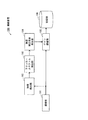
本実施の形態の撮像装置の構成について図1を参照しつつ説明する。図1は本実施の形態の撮像装置の構成図である。
撮像装置1は、CCD(Charge Coupled Device)カメラモジュール2と、画像処理ユニット3と、DRAM(Dynamic RandomAccess Memory)4と、メモリカード5とを備える。撮像装置1は高速度撮影機能等を有し、設定されたフレームレートで撮影を行う。なお、撮像装置1に設定されたフレームレートが蛍光灯フリッカー周波数より高いことがある。
<Configuration of imaging device>
The configuration of the imaging apparatus according to the present embodiment will be described with reference to FIG. FIG. 1 is a configuration diagram of an imaging apparatus according to the present embodiment.
The imaging apparatus 1 includes a CCD (Charge Coupled Device) camera module 2, an image processing unit 3, a DRAM (Dynamic Random Access Memory) 4, and a
CCDカメラモジュール2は、撮像した画像に係る8ビットの輝度値(Y)及び色相値(Cb,Cr)のデータを交互に画像処理ユニット3の後述する画像入力部14へ出力する。
画像処理ユニット3は、CCDカメラモジュール2から入力される画像を符号化するためのものであって、その詳細は後述する。
The CCD camera module 2 alternately outputs 8-bit luminance value (Y) and hue value (Cb, Cr) data relating to the captured image to an image input unit 14 (to be described later) of the image processing unit 3.
The image processing unit 3 is for encoding an image input from the CCD camera module 2, and details thereof will be described later.
DRAM4の入力フレーム記憶領域6には、CCDカメラモジュール2によって撮像された画像を構成する各画像フレームの輝度値(Y)及び色相値(Cb、Cr)のデータが画像処理ユニット3の画像入力部14によって格納される。また、DRAM4の参照フレーム記憶領域7a〜7dには、画像処理ユニット3による画像フレームの符号化の際に得られる画像フレームが参照フレームの候補として格納される。なお、参照フレーム記憶領域7a〜7dに格納される画像フレームを「候補参照フレーム」と言うことにする。但し、本実施の形態では、後述するように、4枚分の候補参照フレームが1フレームずつ参照フレーム記憶領域7a〜7dに格納される。
In the input frame storage area 6 of the DRAM 4, the luminance value (Y) and hue value (Cb, Cr) data of each image frame constituting the image captured by the CCD camera module 2 is stored in the image input unit of the image processing unit 3. 14 is stored. In the reference
メモリカード5には、画像処理ユニット3による画像の符号化によって得られる符号化データが格納される。
[画像処理ユニット3の構成]
画像処理ユニット3は、図1に示すように、プロセッサ11と、DRAM制御部12と、メモリカード制御部13と、画像入力部14と、フレーム輝度検出部15と、フリッカースペクトル検出部16と、輝度推定部17と、符号化部18と、内部バス19とを備える。プロセッサ11、DRAM制御部12、メモリカード制御部13、画像入力部14、及び符号化部18は、夫々、内部バス19に接続されている。
The
[Configuration of Image Processing Unit 3]
As shown in FIG. 1, the image processing unit 3 includes a
プロセッサ11は、例えば、画像処理ユニット3内の各部の起動を内部バス19を介して制御する。DRAM制御部12は、DRAM4へのデータの書き込み、DRAM4からのデータの読み出しを行う。メモリカード制御部13は、メモリカード5へのデータの書き込み、メモリカード5からのデータの読み出しを行う。
画像入力部14は、CCDカメラモジュール2から入力される輝度値(Y)のデータをフレーム輝度検出部15へ出力するとともに、CCDカメラモジュール2から入力される輝度値(Y)のデータ及び色相値(Cb,Cr)のデータを内部バス19を介してDRAM制御部12へ出力する。この輝度値(Y)のデータ及び色相値(Cb,Cr)のデータによって構成される画像フレームはDRAM制御部12によって入力フレーム記憶領域6に格納される。
For example, the
The
フレーム輝度検出部15は、32ビットのカウンタを有する。フレーム輝度検出部15は、フレーム単位で、1フレーム内の画素の輝度値をカウンタを用いて積算し、積算の結果得られた値(以下、「フレーム輝度値」と言う。)をフリッカースペクトル検出部16へ出力する。
フリッカースペクトル検出部16は、フレーム輝度検出部15から入力されるフレーム輝度値を格納するための32ビットのバッファを512個有し、512フレーム分のフレーム輝度値を記憶することができるようになっている。
The frame
The flicker
フリッカースペクトル検出部16は、フレーム輝度検出部15から新たなフレーム輝度値が入力されると、バッファに格納されている最も古いフレーム輝度値を入力された新たなフレーム輝度値に置き換える。そして、フリッカースペクトル検出部16は、512個のバッファに格納されているフレーム輝度値を時系列に512個サンプリングし、高速フーリエ変換(以下、「FFT」と言う。)を実行して512個の32ビットのスペクトル値を求める。
When a new frame luminance value is input from the frame
続いて、フリッカースペクトル検出部16は、電源周波数50Hzに由来する蛍光灯フリッカーの成分があるか、電源周波数60Hzに由来する蛍光灯フリッカーの成分があるかを判定するために、次の処理を行う。
フリッカースペクトル検出部16は、100Hzのスペクトル値と120Hzのスペクトル値とを比較する。
Subsequently, the flicker
The
100Hzのスペクトル値が120Hzのスペクトル値より大きい場合、フリッカースペクトル検出部16は、100Hzのスペクトル値を閾値と比較し、100Hzのスペクトル値が閾値を超える場合には電源周波数50Hzに由来する蛍光灯フリッカーの成分があると判定し、超えない場合には蛍光灯フリッカーの成分がないと判定する。
一方、100Hzのスペクトル値が120Hzのスペクトル値より大きくない場合、フリッカースペクトル検出部16は、120Hzのスペクトル値を閾値と比較し、120Hzのスペクトル値が閾値を超える場合には電源周波数60Hzに由来する蛍光灯フリッカーの成分があると判定し、超えない場合には蛍光灯フリッカーの成分がないと判定する。
When the spectral value of 100 Hz is larger than the spectral value of 120 Hz, the flicker
On the other hand, when the 100 Hz spectrum value is not larger than the 120 Hz spectrum value, the flicker
フリッカースペクトル検出部16は、求めたスペクトル値と判定結果を示すフリッカー情報とを輝度推定部17へ出力する。
但し、上記の閾値を、例えば、センサによって特性が異なることを考慮して、予め蛍光灯フリッカーがある環境と蛍光灯フリッカーのない環境との夫々で撮像を行い、その撮像結果を用いて決定することが好ましい。
The flicker
However, the above threshold value is determined using, for example, imaging in advance in an environment where there is fluorescent flicker and an environment where there is no fluorescent flicker, considering that the characteristics differ depending on the sensor, for example. It is preferable.
輝度推定部17は、フリッカースペクトル検出部16から入力されるフリッカー情報の内容に応じて下記の処理を行って画像フレームの撮像時の光源の輝度を推定する。
フリッカー情報が電源周波数50Hzに由来する蛍光灯フリッカーの成分があることを示す場合、輝度推定部17は、フリッカースペクトル検出部16から入力されるスペクトル値の中から、100Hzの倍数の100Hz、200Hz、300Hz、・・・の各周波数のスペクトル値を取り出す。そして、輝度推定部17は、取り出した各周波数のスペクトル値を用いて逆高速フーリエ変換(以下、「IFFT」と言う。)を実行して512フレーム分の輝度値を求め、求めた輝度値を光源の輝度推定値として符号化部18の後述する動き探索部31へ出力する。
The
When the flicker information indicates that there is a fluorescent flicker component derived from the power supply frequency of 50 Hz, the
また、フリッカー情報が電源周波数60Hzに由来する蛍光灯フリッカーの成分があることを示す場合、輝度推定部17は、フリッカースペクトル検出部16から入力されるスペクトル値の中から、120Hzの倍数の120Hz、240Hz、360Hz、・・・の各周波数のスペクトル値を取り出す。そして、輝度推定部17は、取り出した各周波数のスペクトル値を用いてIFFTを実行して512フレーム分の輝度値を求め、求めた輝度値を光源の輝度推定値として符号化部18の動き探索部31へ出力する。
Further, when the flicker information indicates that there is a fluorescent flicker component derived from the
上記の処理を行うことによって、蛍光灯フリッカーに関係しない周波数成分を除外し、512フレーム分夫々の蛍光灯フリッカーに由来する輝度変化のみ推定できる。
さらに、フリッカー情報が蛍光灯フリッカーの成分がないことを示す場合、輝度推定部17は、予め定められた固定値を光源の輝度推定値として符号化部18の動き探索部31へ出力する。
By performing the above processing, it is possible to exclude frequency components not related to the fluorescent lamp flicker and to estimate only the luminance change derived from the fluorescent lamp flicker for 512 frames.
Further, when the flicker information indicates that there is no fluorescent light flicker component, the
なお、蛍光灯フリッカーは周期性があるので、継続する画像フレームも同様のパターンを示すことが予想されるため、FFT演算及びIFFT演算を毎画像フレーム行ってもよいし、FFT演算及びIFFT演算を一定間隔で間引いてもよい。
符号化部18は、CCDカメラモジュール2によって撮像され、入力フレーム記憶領域6に記憶されている画像フレームの符号化を、輝度推定部17から入力される光源の輝度推定値を用いて行うものである。なお、本実施の形態では、符号化部18はMPEG−4 AVCに従う動画像符号化を行うものとする。
Since fluorescent lamp flicker has periodicity, it is expected that a continuous image frame will show the same pattern. Therefore, FFT calculation and IFFT calculation may be performed every image frame, or FFT calculation and IFFT calculation are performed. You may thin out at regular intervals.
The
(符号化部18の構成)
図1の符号化部18について図2を参照しつつ説明する。図2は図1の符号化部18の構成図である。なお、図2では、図の簡略化のため、符号化部18とDRAM4との間にある内部バス19及びDRAM制御部12を省略し、符号化部18とメモリカード5との間にある内部バス19及びメモリカード制御部13を省略している。
(Configuration of encoding unit 18)
The
符号化部18は、動き探索部31と、差分部32と、DCT部33と、量子化部34と、可変長符号化部35と、逆量子化部36と、IDCT部37とを備える。
但し、MPEG−4 AVCにおける動画像符号化では、別の画像フレームを参照フレームとして使用することが可能である。そこで、本実施の形態では常に過去の4フレーム分の候補参照フレームをリングバッファ状に参照フレーム記憶領域7a〜7dに蓄積しておき、それらを参照フレームに利用できる構成にする。なお、リングバッファ構造の場合、符号化の開始からフレーム番号をカウントしておけばフレーム番号からメモリ位置を一意に特定できる。
The
However, in moving picture coding in MPEG-4 AVC, it is possible to use another picture frame as a reference frame. Therefore, in the present embodiment, candidate reference frames for the past four frames are always accumulated in the reference
以下では、説明の便宜上、符号化部18はフレーム番号n−1の画像フレームまで符号化を完了しており、フレーム番号nの画像フレームを符号化する場合を例に挙げて記載する。
入力フレーム記憶領域6に記憶されているフレーム番号nの画像フレームが、DRAM制御部12によって読み出され、内部バス19を介して動き探索部31及び差分部32に入力される。
In the following, for the sake of convenience of explanation, the
The image frame of frame number n stored in the input frame storage area 6 is read by the
動き探索部31は、輝度推定部17から入力されるフレーム番号nの画像フレームの撮像時の輝度の輝度推定値Ynの逆数を算出し、輝度推定値Ynの逆数1/Ynをフレーム番号nの画像フレームの輝度補正係数Gnとして蓄積する。但し、動き探索部31は、フレーム番号n−i(i=1,2,3,4)の画像フレームの符号化の際に、フレーム番号n−iの画像フレームの撮像時の輝度推定値Yn-iの逆数を算出することによってフレーム番号n−iの画像フレームの輝度補正係数Gn-i(=1/Yn-i)を算出し、算出した輝度補正係数Gn-iを蓄積している。なお、この輝度補正係数Gn-iがフレーム番号n−i(i=1,2,3,4)の候補参照フレームの輝度補正係数である。
続いて、動き探索部31は、参照フレーム記憶領域7a〜7dに格納されている過去4フレーム分の候補参照フレームの中から、輝度補正係数Gnに最も近い輝度補正係数の候補参照フレームを参照フレームに決定する。そして、動き探索部31は、参照フレームに決定した候補参照フレームを内部バス19及びDRAM制御部12を介して参照フレーム記憶領域7a〜7dから取得する。以下、説明の便宜上、参照フレームに決定された候補参照フレームはフレーム番号n−n’の候補参照フレームであるとし、フレーム番号n−n’の候補参照フレームの輝度補正係数をGn-n'と記載する。
Subsequently, the
更に続いて、動き探索部31は、矩形領域のサイズがl×mである各マクロブロックについて、参照フレームとして決定されたフレーム番号n−n’の候補参照フレームを用いて、下記の式(2)の絶対値差SADが最小となるx’及びy’を探索することによって動きベクトルの検出を行う。そして、動き探索部31は、検出した動きベクトルを用いて動き補償を行い、動き補償により得られた予測信号を差分部32へ出力する。
Subsequently, the
但し、| |は絶対値を表す記号である。また、fn(x,y)は符号化の対象であるフレーム番号nの画像フレームの座標(x,y)における輝度値、fn-n'(x,y)は参照フレームとして決定されたフレーム番号n−n’の候補参照フレームの座標(x,y)における輝度値である。
差分部32は、フレーム番号nの画像フレームの画像から動き探索部31から入力される予測信号を減算して残差信号を生成する。DCT部33は、差分部32から入力される残差信号を離散コサイン変換(以下、「DCT」と言う。)することによってDCT係数を生成する。量子化部34は、DCT部33から入力されるDCT係数を量子化することによって量子化値を算出する。可変長符号化部35は、量子化部34から入力される量子化値を可変長符号化することによってフレーム番号nの画像フレームに関する符号化データを生成し、生成した符号化データを内部バス19及びメモリカード制御部13を介してメモリカード5に格納する。
However, || is a symbol representing an absolute value. Further, f n (x, y) is a luminance value at the coordinates (x, y) of the image frame of frame number n to be encoded, and f n−n ′ (x, y) is a frame number determined as a reference frame. It is a luminance value at the coordinates (x, y) of the candidate reference frame of nn ′.
The
逆量子化部36は、量子化部34から入力される量子化値を逆量子化することによって逆量子化値を算出し、IDCT部37は、逆量子化部36から入力される逆量子化値を逆離散コサイン変換(以下、「IDCT」と言う。)する。これらの処理によってフレーム番号nの画像フレームが復号される。IDCT部37は、復号されたフレーム番号nの画像フレームを、フレーム番号nの候補参照フレームとして、最も古いフレーム番号の候補参照フレーム(ここでは、フレーム番号n−4の候補参照フレーム)が格納されている参照フレーム記憶領域に、内部バス19及びDRAM制御部12を介して格納する。これにより、フレーム番号n+1の画像フレームの符号化の際、参照フレーム記憶領域7a〜7dにはフレーム番号n−3〜nの4フレーム分の候補参照フレームが格納されていることになる。
The
<撮像装置1の動作>
以下、図1の撮像装置1の動作について図3を参照しつつ説明する。図3は図1の撮像装置1による画像処理の手順を示すフローチャートであり、1つの画像フレームに対する処理の流れを示す。
CCDカメラモジュール2によって画像の撮像が行われ、撮像された画像の輝度値(Y)のデータが画像入力部14によってフレーム輝度検出部15に入力され、当該画像の画像フレームを構成する輝度値(Y)及び色相値(Cb,Cr)のデータが画像入力部14によって内部バス19及びDRAM制御部12を介して入力フレーム記憶領域6に格納される(ステップS1)。
<Operation of Imaging Device 1>
Hereinafter, the operation of the imaging apparatus 1 of FIG. 1 will be described with reference to FIG. FIG. 3 is a flowchart showing a procedure of image processing by the imaging apparatus 1 in FIG. 1, and shows a flow of processing for one image frame.
An image is picked up by the CCD camera module 2, and data of the luminance value (Y) of the picked-up image is input to the frame
フレーム輝度検出部15は、フレーム単位で、1フレーム内の画素の輝度値を積算してフレーム輝度値を算出する(ステップS2)。フリッカースペクトル検出部16は、フレーム輝度検出部15によって算出された512フレーム分のフレーム輝度値を用いて512個のスペクトル値を求める(ステップS3)。フリッカースペクトル検出部16は、算出したスペクトル値に基づいて電源周波数50Hzに由来する蛍光灯フリッカーの成分があるか、電源周波数60Hzに由来する蛍光灯フリッカーの成分があるか、蛍光灯フリッカーの成分がないかを判定する(ステップS4)。
The frame
電源周波数50Hzに由来する蛍光灯フリッカーの成分があると判定された場合(S4:電源50Hz)、輝度推定部17は、フリッカースペクトル検出部16によって求められた100Hz,200Hz,300Hz,・・・のスペクトル値を用いて512フレーム分の各画像フレームの撮像時の光源の輝度推定値を算出する(ステップS5)。また、電源周波数60Hzに由来する蛍光灯フリッカーの成分があると判定された場合(S4:電源60Hz)、輝度推定部17は、フリッカースペクトル検出部16によって求められた120Hz,240Hz,360Hz,・・・のスペクトル値を用いて512フレーム分の各画像フレームの撮像時の光源の輝度推定値を算出する(ステップS6)。また、蛍光灯フリッカーの成分がないと判定された場合(S4:なし)、輝度推定部17は、固定値を画像フレームの撮像時の光源の輝度推定値に決定する(ステップS7)。
When it is determined that there is a fluorescent lamp flicker component derived from the power supply frequency 50 Hz (S4: power supply 50 Hz), the
符号化対象の画像フレームが入力フレーム記憶領域6から動き探索部31及び差分部32にDRAM制御部12及び内部バス19を介して入力される。動き探索部31は、輝度推定部17によって算出或いは決定された符号化対象の画像フレームの輝度推定値から上述したようにして当該画像フレームの輝度補正係数を求め、蓄積する。そして、動き探索部31は、参照フレーム記憶領域7a〜7dに記憶されている過去4フレーム分の候補参照フレームの中から、符号化対象の画像フレームの輝度補正係数に最も近い輝度補正係数の候補参照画像フレームを参照フレームに決定する(ステップS8)。なお、過去4フレーム分の各画像フレームの符号化の際に各画像フレームの輝度補正係数が算出されて蓄積されており、この蓄積されている各輝度補正係数が過去4フレーム分の各候補参照フレームの輝度補正係数として用いられる。
An image frame to be encoded is input from the input frame storage area 6 to the
続いて、動き探索部31は、参照フレームとして決定された候補参照フレームを参照フレーム記憶領域7a〜7dから内部バス19及びDRAM制御部12を介して取得し、取得した候補参照フレームを用いて上記の式(2)の絶対値差SADが最小となるx’及びy’を探索することによって動きベクトルの検出を行う(ステップS9)。
動き探索部31は検出した動きベクトルに基づいて動き補償を行って予測信号を生成する。そして、差分部32は符号化対象の画像フレームの画像から予測信号を減算して残差信号を生成し、DCT部33、量子化部34及び可変長符号化部35は残差信号から符号化データを生成し、可変長符号化部35は生成した符号化データを内部バス19及びメモリカード制御部13を介してメモリカード5に格納する。また、逆量子化部36及びIDCT部37は量子化部34から出力された量子化値から符号化対象の画像フレームを復号し、IDCT部37は最も古いフレーム番号の候補参照フレームが格納されている参照フレーム記憶領域に復号した画像フレームを候補参照フレームとして内部バス19及びDRAM制御部12を介して格納する(ステップS10)。
Subsequently, the
The
上述した実施の形態によれば、512フレーム分の画像フレームのフレーム輝度値から蛍光灯フリッカーの成分の分析を行い、光源の輝度を推定しているため、光源の輝度の高い推定精度が得られる。
動き探索において、符号化対象の画像フレームの撮像時の光源の輝度推定値に最も近い輝度推定値の候補参照フレームを参照フレームに決定し、更に、符号化対象の画像フレームと参照フレームとして決定された候補参照フレームとの輝度差を係数補正しながら動きベクトルの検出を行う。これによって、撮影時の光源の輝度の変化に起因する動きベクトルの誤探索を軽減しつつ、効率の良い符号化を行うことができる。
According to the embodiment described above, since the fluorescent light flicker component is analyzed from the frame luminance values of the image frames for 512 frames and the luminance of the light source is estimated, high estimation accuracy of the luminance of the light source can be obtained. .
In motion search, a candidate reference frame having a luminance estimated value closest to the luminance estimated value of the light source at the time of capturing the image frame to be encoded is determined as a reference frame, and further, determined as an image frame to be encoded and a reference frame. The motion vector is detected while correcting the luminance difference with the candidate reference frame. Thus, efficient coding can be performed while reducing erroneous search for motion vectors due to changes in the luminance of the light source during shooting.
画像フレームそのものを輝度補正することなく画像フレームの符号化を行っているため、高速度撮影の場合、符号化データは蛍光灯フリッカーの現象自体の情報を含むことができ、蛍光灯フリッカーの現象自体を撮像対象とする用途にも適用することができる。
図11を用いて説明した従来技術のようにゲイン値を符号化データに含める必要がないため、他の符号化器との互換性を持たせることができる。
Since the image frame is encoded without correcting the luminance of the image frame itself, in the case of high-speed shooting, the encoded data can include information on the phenomenon of the fluorescent lamp flicker itself, and the phenomenon of the fluorescent lamp flicker itself It can also be applied to applications for which imaging is performed.
Unlike the prior art described with reference to FIG. 11, it is not necessary to include a gain value in encoded data, so that compatibility with other encoders can be achieved.
≪第2の実施の形態≫
以下、本発明の第2の実施の形態について図面を参照しつつ説明する。但し、本実施の形態では、符号化パラメータは動き探索に用いる参照フレームである。
第1の実施の形態の符号化部18は、過去4フレーム分の候補参照フレームのうち符号化対象の画像フレームの輝度補正係数に最も近い輝度補正係数の候補参照フレームを参照フレームに決定し、補正されていない輝度値及び輝度補正係数を用いた動きベクトルの検出を行う。これに対して、本実施の形態の符号化部18aは、過去4フレーム分の候補参照フレームのうち最も小さい輝度補正係数の候補参照フレームを参照フレームに決定し、補正が行われた輝度値を用いた動きベクトルの検出を行う。
<< Second Embodiment >>
The second embodiment of the present invention will be described below with reference to the drawings. However, in the present embodiment, the encoding parameter is a reference frame used for motion search.
The
<撮像装置の構成>
本実施の形態の撮像装置の構成について図4を参照しつつ説明する。図4は本実施の形態の撮像装置の構成図である。但し、本実施の形態において、第1の実施の形態の構成要素と実質的に同じ構成要素には同じ符号を付し、その説明が適用できるため本実施の形態ではその説明を省略する。
<Configuration of imaging device>
The configuration of the imaging apparatus according to the present embodiment will be described with reference to FIG. FIG. 4 is a configuration diagram of the imaging apparatus according to the present embodiment. However, in the present embodiment, components that are substantially the same as those in the first embodiment are denoted by the same reference numerals, and the description thereof can be applied.
撮像装置1aは、CCDカメラモジュール2と、画像処理ユニット3aと、DRAM4と、メモリカード5とを備える。
画像処理ユニット3aは、CCDカメラモジュール2から入力される画像を符号化するためのものであって、以下、画像処理ユニット3aについて説明する。
[画像処理ユニット3aの構成]
画像処理ユニット3aは、図4に示すように、プロセッサ11と、DRAM制御部12と、メモリカード制御部13と、画像入力部14と、フレーム輝度検出部15と、フリッカースペクトル検出部16と、輝度推定部17と、ゲイン調整部51と、符号化部18aと、内部バス19とを備える。プロセッサ11、DRAM制御部12、メモリカード制御部13、ゲイン調整部51、及び符号化部18aは、夫々、内部バス19に接続されている。なお、画像入力部14は、画像の輝度値(Y)のデータをフレーム輝度検出部15へ出力し、画像の輝度値(Y)及び色相値(Cr,Cb)のデータをゲイン調整部51へ出力する。また、輝度推定部17は画像フレームの撮像時の光源の輝度推定値をゲイン調整部51及び符号化部18aの後述する動き探索部31aへ出力する。
The imaging device 1a includes a CCD camera module 2, an image processing unit 3a, a DRAM 4, and a
The image processing unit 3a is for encoding an image input from the CCD camera module 2, and the image processing unit 3a will be described below.
[Configuration of Image Processing Unit 3a]
As shown in FIG. 4, the image processing unit 3a includes a
ゲイン調整部51の説明の便宜上フレーム番号nの画像フレームを対象に説明するが、ゲイン調整部51はフレーム番号n以外のフレーム番号の画像フレームの場合も同様の処理を実行する。ゲイン調整部51は、輝度推定部17から入力されるフレーム番号nの画像フレームの輝度推定値Ynの逆数を算出し、算出した輝度推定値の逆数1/Ynを画像入力部14から入力されるフレーム番号nの画像フレームを構成する輝度値(Y)に乗算して輝度値(Y)を補正する。そして、ゲイン調整部51は、フレーム番号nの画像フレームを構成する輝度補正が施された輝度値(Y)及び色相値(Cb,Cr)を内部バス19を介してDRAM制御部12へ出力する。フレーム番号nの画像フレームを構成する輝度補正が施された輝度値(Y)及び色相値(Cb,Cr)はDRAM制御部12によって入力フレーム記憶領域6に格納される。このように、本実施の形態において入力フレーム記憶領域6に記憶される画像フレームは、第1の実施の形態と異なり、輝度値(Y)が輝度補正された画像フレームである。
For convenience of description of the
符号化部18aは、CCDカメラモジュール2によって撮像され、入力フレーム記憶領域6に記憶されている画像フレームの符号化を、輝度推定部17から入力される光源の輝度推定値を用いて行うものである。なお、本実施の形態では、符号化部18aはMPEG−4 AVCに従う動画像符号化を行うものとする。
(符号化器18aの構成)
図4の符号化器18aについて図5を参照しつつ説明する。図5は図4の符号化部18aの構成図である。なお、図5では、図の簡略化のため、符号化部18aとDRAM4との間にある内部バス19及びDRAM制御部12を省略し、符号化部18aとメモリカード5との間にある内部バス19及びメモリカード制御部13を省略している。
The
(Configuration of
The
符号化部18aは、動き探索部31aと、差分部32と、DCT部33と、量子化部34と、可変長符号化部35と、逆量子化部36と、IDCT部37とを備える。但し、本実施の形態においても、第1の実施の形態と同様、常に過去の4フレーム分の候補参照フレームをリングバッファ状に参照フレーム記憶領域7a〜7dに蓄積しておき、それらを参照フレームに利用できる構成にする。
The
以下では、説明の便宜上、符号化部18aはフレーム番号n−1の画像フレームまで符号化を完了しており、フレーム番号nの画像フレームを符号化する場合を例に挙げて記載する。
動き探索部31aは、輝度推定部17から入力されるフレーム番号nの画像フレームの撮像時の輝度推定値Ynの逆数を算出し、輝度推定値Ynの逆数1/Ynをフレーム番号nの画像フレームの輝度補正係数Gnとして蓄積する。但し、動き探索部31aは、フレーム番号n−i(i=1,2,3,4)の画像フレームの符号化の際に、フレーム番号n−iの画像フレームの撮像時の輝度推定値Yn-iの逆数を算出することによってフレーム番号n−iの画像フレームの輝度補正係数Gn-i(=1/Yn-i)を算出し、算出した輝度補正係数Gn-iを蓄積している。なお、この輝度補正係数Gn-iがフレーム番号n−i(i=1,2,3,4)の候補参照フレームの輝度補正係数である。
In the following, for the sake of convenience of explanation, the
続いて、動き探索部31aは、参照フレーム記憶領域7a〜7dに格納されている過去4フレーム分の候補参照フレームの中から、最も小さい輝度補正係数の候補参照フレームを参照フレームに決定する。そして、動き探索部31aは、参照フレームに決定した候補参照フレームを内部バス19及びDRAM制御部12を介して参照フレーム記憶領域7a〜7dから取得する。以下、説明の便宜上、参照フレームに決定された候補参照フレームはフレーム番号n−n’の候補参照フレームであるとする。
Subsequently, the
更に続いて、動き探索部31aは、矩形領域のサイズがl×mである各マクロブロックについて、参照フレームとして決定されたフレーム番号n−n’の候補参照フレームを用いて、下記の式(3)の絶対値差SADが最小となるx’及びy’を探索することによって動きベクトルの検出を行う。そして、動き探索部31aは、検出した動きベクトルを用いて動き補償を行い、動き補償により得られた予測信号を差分部32へ出力する。
Subsequently, the
但し、| |は絶対値を表す記号である。また、fn(x,y)は符号化の対象であるフレーム番号nの画像フレームの座標(x,y)における輝度値、fn-n'(x,y)は参照フレームとして決定されたフレーム番号n−n’の候補参照フレームの座標(x,y)における輝度値である。
なお、ゲイン調整部51によって輝度補正が施されていることを踏まえ、評価関数として従来例と同様のものを用いている。
However, || is a symbol representing an absolute value. Further, f n (x, y) is a luminance value at the coordinates (x, y) of the image frame of frame number n to be encoded, and f n−n ′ (x, y) is a frame number determined as a reference frame. It is a luminance value at the coordinates (x, y) of the candidate reference frame of nn ′.
Note that the same evaluation function as that in the conventional example is used based on the fact that the luminance adjustment is performed by the
<撮像装置1aの動作>
以下、図4の撮像装置1aの動作について図6を参照しつつ説明する。図6は図4の撮像装置1aによる画像処理の手順を示すフローチャートであり、1つの画像フレームに対する処理の流れを示す。
CCDカメラモジュール2によって画像の撮像が行われ、撮像された画像の輝度値(Y)のデータが画像入力部14によってフレーム輝度検出部15に入力され、当該画像の画像フレームを構成する輝度値(Y)及び色相値(Cb,Cr)のデータがゲイン調整部51に入力される(ステップS31)。
<Operation of Imaging Device 1a>
Hereinafter, the operation of the imaging apparatus 1a of FIG. 4 will be described with reference to FIG. FIG. 6 is a flowchart showing a procedure of image processing by the imaging apparatus 1a of FIG. 4, and shows a flow of processing for one image frame.
An image is picked up by the CCD camera module 2, and data of the luminance value (Y) of the picked-up image is input to the frame
フレーム輝度検出部15はステップS2と実質的に同じ処理を行い(ステップS32)、フリッカースペクトル検出部16はステップS3と実質的に同じ処理を行う(ステップS33)。続いて、輝度推定部17はステップS4〜S7と実質的に同じ処理を行う(ステップS34〜S37)。ゲイン調整部51は、輝度推定部17によって算出され或いは決定された輝度推定値の逆数を算出し、画像入力部14から入力された同じフレーム番号の画像フレームの輝度値(Y)に算出した輝度推定値の逆数を乗算して輝度値(Y)を補正する。そして、ゲイン調整部51は、輝度補正が施された輝度値(Y)及び色相値(Cb,Cr)をそのフレーム番号の画像フレームのデータとして内部バス19及びDRAM制御部12を介して入力フレーム記憶領域6に格納する(ステップS38)。
The frame
符号化対象の画像フレームが入力フレーム記憶領域6から動き探索部31a及び差分部32にDRAM制御部12及び内部バス19を介して入力される。動き探索部31aは、輝度推定部17によって算出或いは決定された符号化対象の画像フレームの輝度推定値から上述したようにして当該画像フレームの輝度補正係数を求め、蓄積する。そして、動き探索部31aは、過去の4フレーム分の候補参照フレームの中から、最も小さい輝度補正係数の候補参照フレームを参照フレームに決定する(ステップS39)。なお、過去4フレーム分の各画像フレームの符号化の際に各画像フレームの輝度補正係数が算出されて蓄積されており、この蓄積されている各輝度補正係数が過去4フレーム分の各候補参照フレームの輝度補正係数として用いられる。
An image frame to be encoded is input from the input frame storage area 6 to the
続いて、動き探索部31aは、参照フレームとして決定された候補参照フレームを参照フレーム記憶領域7a〜7dから内部バス19及びDRAM制御部12を介して取得し、取得した候補参照フレームを用いて上記の式(3)の絶対値差SADが最小となるx’及びy’を探索することによって動きベクトルの検出を行う(ステップS40)。
動き探索部31aは検出した動きベクトルに基づいて動き補償を行って予測信号を生成する。そして、差分部32、DCT部33、量子化部34、及び可変長符号化部35は符号化処理を行い、逆量子化部36及びIDCT部37は復号処理を行う(ステップS41)。
Subsequently, the
The
上述した実施の形態によれば、参照フレームとして用いられる候補参照フレームは撮影時の光源の輝度が最も高かったもの、即ち、S/N比が最も高い高品質なものであるため、効率の良い符号化を行うことができる。
≪第3の実施の形態≫
以下、本発明の第3の実施の形態について図面を参照しつつ説明する。但し、本実施の形態では、符号化パラメータは符号化対象の画像フレームの符号化を行う符号化部である。
According to the above-described embodiment, the candidate reference frame used as the reference frame has the highest luminance of the light source at the time of shooting, that is, the high quality with the highest S / N ratio. Encoding can be performed.
<< Third Embodiment >>
The third embodiment of the present invention will be described below with reference to the drawings. However, in the present embodiment, the encoding parameter is an encoding unit that encodes an image frame to be encoded.
第1及び第2の実施の形態の撮像装置1,1aは、1つの符号化部を用いて符号化を行う。これに対して、第3の実施の形態の撮像装置1bは、3つの符号化部を用いて並列して符号化を行う。
<撮像装置の構成>
本実施の形態の撮像装置の構成について図7を参照しつつ説明する。図7は本実施の形態の撮像装置の構成図である。但し、本実施の形態において、第1の実施の形態の構成要素と実質的に同じ構成要素には同じ符号を付し、その説明が適用できるため本実施の形態ではその説明を省略する。
The imaging devices 1 and 1a according to the first and second embodiments perform encoding using one encoding unit. In contrast, the imaging device 1b according to the third embodiment performs encoding in parallel using three encoding units.
<Configuration of imaging device>
The configuration of the imaging apparatus according to the present embodiment will be described with reference to FIG. FIG. 7 is a configuration diagram of the imaging apparatus of the present embodiment. However, in the present embodiment, components that are substantially the same as those in the first embodiment are denoted by the same reference numerals, and the description thereof can be applied.
撮像装置1bは、CCDカメラモジュール2と、画像処理ユニット3bと、DRAM4bと、メモリカード5とを備える。
DRAM4bには、画像処理ユニット3b内の符号化部72,73,74の各々に対応した参照フレーム記憶領域72a,73a,74aがあり、参照フレーム記憶領域72a,73a,74aには夫々1フレーム分の参照フレームが記憶される。
The imaging device 1b includes a CCD camera module 2, an image processing unit 3b, a
The
画像処理ユニット3bは、CCDカメラモジュール2から入力される画像を符号化するためのものであって、以下、画像処理ユニット3bについて説明する。
[画像処理ユニット3bの構成]
画像処理ユニット3bは、図7に示すように、プロセッサ11と、DRAM制御部12と、メモリカード制御部13と、画像入力部14と、フレーム輝度検出部15と、フリッカースペクトル検出部16と、輝度推定部17と、分配部71と、符号化部72,73,74と、合成部75と、内部バス19とを備える。プロセッサ11、DRAM制御部12、メモリカード制御部13、画像入力部14、分配部71、符号化部72,73,74及び合成部75は、夫々、内部バス19に接続されている。なお、輝度推定部17は光源の輝度推定値を分配部71へ出力する。
The image processing unit 3b is for encoding an image input from the CCD camera module 2, and the image processing unit 3b will be described below.
[Configuration of Image Processing Unit 3b]
As shown in FIG. 7, the image processing unit 3b includes a
分配部71は、符号化部72〜74の夫々について、現時点で符号化を実行中の画像フレームの撮像時の光源の輝度推定値を、現時点で符号化を実行していなければ直近に符号化した画像フレームの撮像時の光源の輝度推定値を蓄積している。
分配部71には輝度推定部17から符号化対象の画像フレームの撮像時の光源の輝度推定値が入力される。分配部71は、符号化処理を実行していない符号化部72〜74のうち、符号化対象の画像フレームの撮像時の光源の輝度推定値に直近に符号化した画像フレームの撮像時の光源の輝度推定値が最も近い符号化部を、符号化対象の画像フレームを符号化する符号化部に決定する。そして、分配部71は、入力フレーム記憶領域6から内部バス19及びDRAM制御部12を介して符号化対象の画像フレームを取得し、取得した符号化対象の画像フレーム及び当該符号化対象の画像フレームの撮像時の光源の輝度推定値を決定した符号化部へ出力する。これと共に、分配部71は決定した符号化部に対応して蓄積していた光源の輝度推定値を符号化対象の画像フレームの撮像時の光源の輝度推定値に更新する。
For each of the
The
符号化部72,73,74は、夫々、CCDカメラモジュール2によって撮像され、分配部71から入力された画像フレームの符号化を行い、符号化データを合成部75へ出力するものであって、その詳細は後述する。なお、本実施の形態では、符号化部72,73,74はMPEG−4 AVCに従う動画像符号化を行うものとする。
合成部75は、符号化部72,73,74から入力される符号化データをフレーム番号の順番に従って一つの符号化データに連結し、連結した符号化データを内部バス19を介してメモリカード制御部13へ出力する。この連結された符号化データはメモリカード制御部13によってメモリカード5に格納される。
The
The
(符号化部72,73,74の構成)
図7の符号化部72について図8を参照しつつ説明する。図8は図7の符号化部72の構成図である。なお、図8では、図の簡略化のため、符号化部72とDRAM4との間にある内部バス19及びDRAM制御部12を省略している。但し、本実施の形態では、符号化部73,74として符号化部72と実質的に同じ構成及び同じ動作を行う符号化部を利用するものとし、この場合、符号化部72の説明が適用できるため本実施の形態では符号化部73,74の説明を省略する。
(Configuration of
The
符号化部72は、動き探索部31bと、差分部32と、DCT部33と、量子化部34と、可変長符号化部35と、逆量子化部36と、IDCT部37とを備える。
以下において、符号化部72がこれから符号化を行う画像フレームのフレーム番号をn、符号化部72が直近に符号化を行った画像フレームのフレーム番号をn−n’とする。
動き探索部31bは、分配部71から入力されるフレーム番号nの画像フレームの撮像時の光源の輝度推定値Ynの逆数を算出し、輝度推定値Ynの逆数1/Ynをフレーム番号nの画像フレームの輝度補正係数Gnとして蓄積する。なお、動き探索部31bは、符号化部72がフレーム番号n−n’の画像フレームを符号化する際にフレーム番号n−n’の画像フレームの撮像時の光源の輝度推定値Yn-n'の逆数を算出することによってフレーム番号n−n’の輝度補正係数Gn-n'(=1/Yn-n')を算出し、算出した輝度補正係数Gn-n'を蓄積している。なお、この輝度補正係数Gn-n'がフレーム番号n−n’の参照フレームの輝度補正係数である。
The
In the following, it is assumed that the frame number of the image frame that the
そして、動き探索部31bは、参照フレーム記憶領域72aからフレーム番号n−n’の参照フレームをDRAM制御部12及び内部バス19を介して取得する。続いて、動き探索部31bは、矩形領域のサイズがl×mである各マクロブロックについて、取得したフレーム番号n−n’の参照フレームを用いて、上記の式(2)の絶対値差SADが最小となるx’及びy’を探索することによって動きベクトルの検出を行う。そして、動き探索部31aは、検出した動きベクトルを用いて動き補償を行い、動き補償により得られた予測信号を差分部32へ出力する。
Then, the
なお、本実施の形態では、可変長符号化部35は符号化データを合成部35へ出力し、IDCT部37は、復号されたフレーム番号nの画像フレームを参照フレームとして参照フレーム記憶領域72aに格納する。
<撮像装置1bの動作>
以下、図7の撮像装置1bの動作について図9を参照しつつ説明する。図9は図7の撮像装置1bによる画像処理の手順を示すフローチャートであり、1つの画像フレームに対する処理の流れを示す。
In the present embodiment, the variable
<Operation of Imaging Device 1b>
Hereinafter, the operation of the imaging apparatus 1b of FIG. 7 will be described with reference to FIG. FIG. 9 is a flowchart showing a procedure of image processing by the imaging apparatus 1b of FIG. 7, and shows a flow of processing for one image frame.
CCDカメラモジュール2及び画像入力部14はステップS1と実質的に同じ処理を行う(ステップS51)。
フレーム輝度検出部15はステップS2と実質的に同じ処理を行い(ステップS52)、フリッカースペクトル検出部16はステップS3と実質的に同じ処理を行う(ステップS53)。続いて、輝度推定部17はステップS4〜S7と実質的に同じ処理を行う(ステップS54〜S57)。
The CCD camera module 2 and the
The frame
分配部71は、符号化部72〜74の中から画像フレームの符号化を行う符号化部の決定を上述したようにして行う(ステップS58)。そして、分配部71は、内部バス19及びDRAM制御部12を介して入力フレーム記憶領域6から符号化対象の画像フレームを取得し、取得した符号化対象の画像フレーム及び当該符号化対象の画像フレームの撮像時の光源の輝度推定値を決定した符号化部へ出力する(ステップS59)。なお、この際、分配部71は決定した符号化部に対応して蓄積していた光源の輝度推定値を符号化対象の画像フレームの撮像時の光源の輝度推定値に更新する。
The
ステップS58において決定された符号化部において、動き探索部31bは、分配部71から入力された符号化対象の画像フレームの輝度推定値から上述したようにして当該画像フレームの輝度補正係数を求め、蓄積する。そして、動き探索部31aは、参照フレーム記憶領域に記憶されている参照フレームを用いて、上記の式(2)の絶対値差SADが最小となるx’及びy’を探索することによって動きベクトルの検出を行う(ステップS60)。なお、参照フレームの輝度補正係数は当該参照フレームの元となった画像フレームの符号化の際に算出され、蓄積されている。
In the encoding unit determined in step S58, the
動き探索部31bは検出した動きベクトルに基づいて動き補償を行って予測信号を生成する。そして、差分部32、DCT部33、量子化部34、及び可変長符号化部35は符号化処理を行い、可変長符号化部35は符号化データを合成部75へ出力し、合成部75は入力される符号化データを連結して内部バス19及びメモリカード制御部13を介してメモリカード5に格納する。また、逆量子化部36及びIDCT部37は復号処理を行い、IDCT部37は復号した画像フレームを参照フレームとして内部バス19及びDRAM制御部12を介して自身の符号化部に対応する参照フレーム記憶領域に格納する(ステップS61)。
The
上述した実施の形態によれば、符号化対象の画像フレームの撮像時の光源の輝度推定値に最も近い輝度推定値の画像フレームの符号化を行っていた符号化部を符号化対象の画像フレームの符号化を行う符号化部に決定し、更に、符号化対象の画像フレームと参照フレームとの輝度差を係数補正しながら動きベクトルの検出を行う。これによって、符号化部の並列化による符号化の処理速度の向上が図られるとともに、撮影時の光源の輝度の変化に起因する動きベクトルの誤探索を軽減しつつ、効率の良い符号化を行うことができる。 According to the above-described embodiment, the encoding unit that has encoded the image frame having the luminance estimated value closest to the luminance estimated value of the light source at the time of imaging the image frame to be encoded is the image frame to be encoded. And the motion vector is detected while correcting the luminance difference between the image frame to be encoded and the reference frame. As a result, the coding processing speed is improved by parallelizing the coding units, and efficient coding is performed while reducing erroneous motion vectors due to changes in the luminance of the light source during shooting. be able to.
≪補足≫
本発明は上記の実施の形態に限られるものではなく、例えば、次のようなものであってもよい。
(1)上述した第1及び第3の各実施の形態では、動きベクトル検出部31,31bは動きベクトルの検出に式(2)の評価関数を用いている。しかしながら、動きベクトルの検出に用いる評価関数は上記の式(2)に限られるものではなく、例えば下記の式(4)、(5)の評価関数を用いてもよい。
<Supplement>
The present invention is not limited to the above embodiment, and may be as follows, for example.
(1) In each of the first and third embodiments described above, the
また、上述した第2の実施の形態では、動きベクトル検出部31aは動きベクトルの検出に式(3)の評価関数を用いている。しかしながら、動きベクトルの検出に用いる評価関数は上記の式(3)に限られるものではなく、例えば下記の式(6)、(7)の評価関数を用いてもよい。
In the second embodiment described above, the motion
(2)上記の第1から第3の各実施の形態では、蛍光灯フリッカーの成分の有無を判定するために、フリッカースペクトル検出部16は、100Hzのスペクトル値及び120Hzのスペクトル値を用いているが、これに限られるものではない。例えば、フリッカースペクトル検出部16は、電源周波数50Hzに由来する蛍光灯フリッカーの有無の判定のために、その2倍の周波数(100Hz)の倍数(1倍を除く。)の周波数(200Hz、300Hz、・・・)成分のスペクトル値を用いてもよい。また、フリッカースペクトル検出部16は、電源周波数60Hzに由来する蛍光灯フリッカーの有無の判定のために、その2倍の周波数(120Hz)の倍数(1倍を除く。)の周波数(240Hz、360Hz、・・・)成分のスペクトル値を用いてもよい。
(2) In each of the first to third embodiments described above, the
(3)上記の第1及び第2の各実施の形態では、候補参照フレームが過去4フレーム分の画像フレームであるしているが、これに限られるものではなく、候補参照フレームが過去N(N=2,3,5,6,・・・)フレーム分の画像フレームであってもよい。
また、上記の第3の実施の形態では、符号化部の数が3つであるが、これに限られるものではなく、例えば、符号化部の数はN(N=2,4,5,・・・)であってもよい。
(3) In each of the first and second embodiments described above, the candidate reference frames are image frames for the past four frames. However, the present invention is not limited to this. N = 2, 3, 5, 6,...) Image frames.
In the third embodiment, the number of encoding units is three. However, the number of encoding units is not limited to this. For example, the number of encoding units is N (N = 2, 4, 5, ...).
(4)上記の第1及び第2の各実施の形態では、参照フレームの決定に輝度補正係数を利用しているが、これに限られるものではなく、例えば、フレーム輝度値を用いて参照フレームの決定を行うようにしてもよい。この場合、第1の実施の形態では、動き探索部31は過去の4フレーム分の候補参照フレームの中から符号化対象の画像フレームの撮像時のフレーム輝度値に最も近いフレーム輝度値の候補参照フレームを参照フレームに決定するようにすればよい。また、第2の実施の形態では、動き探索部31aは過去の4フレーム分の候補参照フレームの中から最もフレーム輝度値が大きい候補参照フレームを参照フレームに決定するようにすればよい。
(4) In each of the first and second embodiments described above, the luminance correction coefficient is used to determine the reference frame. However, the present invention is not limited to this. For example, the reference frame is determined using the frame luminance value. May be determined. In this case, in the first embodiment, the
また、上記の第3の実施の形態では、分配部71は画像フレームの撮像時の光源の輝度推定値を用いて符号化対象の画像フレームの分配先を決定しているが、これに限られるものではなく、例えば分配部71は符号化対象の画像フレームの分配先の決定に画像フレームの撮像時の光源の輝度推定値の逆数を用いてもよい。
(5)上記の第3の実施の形態の符号化部72,73,74として、第1及び第2の実施の形態で説明した符号化部18,18aを用いるようにしてもよく、他の一般的な構成の符号化部を用いるようにしてもよい。また、符号化部72,73,74は、評価関数として輝度補正係数を含まない評価関数(例えば、式(3),(6),(7))を用いてもよい。
In the third embodiment, the
(5) The
(6)上記の第1から第3の各実施の形態では、符号化部18,18a,72,73,74はMPEG−4 AVCに従う動画像符号化を行うものとしたが、これに限られるものではなく、過去の画像フレームを参照フレームとして利用する動画像符号化であれば方式は問わない。
(7)上記の第1から第3の各実施の形態では、フレーム輝度検出部15、フリッカースペクトル検出部16及び輝度推定部17によって撮影時の光源の輝度を推定しているが、これに限られるものではなく、例えば、照度センサを撮像装置に設けて照度センサによって光源の輝度を推定するようにしてもよい。
(6) In the first to third embodiments described above, the
(7) In each of the first to third embodiments described above, the luminance of the light source at the time of shooting is estimated by the frame
(8)上記の第1から第3の各実施の形態では、フリッカーのスペクトル値の検出にFFTを用いているが、これに限られるものではなく、フリッカーのスペクトル値を検出することができる手段であればよい。
(9)上記の第1の実施の形態では、フレーム輝度値に相当する輝度補正係数を用いて参照フレームの決定及び動きベクトルの検出の双方を行っているが、これに限られるものではなく、参照フレームの決定及び動きベクトルの検出の何れか一方にのみフレーム輝度値に相当する輝度補正係数を用いるようにしてもよい。但し、輝度補正係数を用いない方では輝度補正係数を固定値の1とみなすことによって従来の通常の符号化技術を適用することができる。何れか一方にのみ輝度補正係数を用いた場合、双方に輝度補正係数を用いた場合に比べ、符号化効率は低下するもののコストの削減が図られる。
(8) In each of the first to third embodiments described above, FFT is used to detect the flicker spectrum value. However, the present invention is not limited to this, and means capable of detecting the flicker spectrum value. If it is.
(9) In the first embodiment, both the determination of the reference frame and the detection of the motion vector are performed using the luminance correction coefficient corresponding to the frame luminance value. However, the present invention is not limited to this. A luminance correction coefficient corresponding to the frame luminance value may be used for only one of the determination of the reference frame and the detection of the motion vector. However, in the case where the luminance correction coefficient is not used, the conventional normal encoding technique can be applied by regarding the luminance correction coefficient as a fixed value of 1. When the luminance correction coefficient is used for only one of them, the coding efficiency is reduced but the cost can be reduced as compared with the case where the luminance correction coefficient is used for both.
(10)上記の第1から第3の各実施の形態では、輝度値(Y)及び色相値(Cb,Cr)を用いているが、これに限られるものではなく、例えばRGBデータやベイヤデータなど輝度に相関があるデータを含むものであればそのまま或いは所定の変換を施すことによって第1から第3の各実施の形態の手法を適用可能である。
(11)上記の第1から第3の各実施の形態では、CCDカメラモジュール2が輝度値(Y)の算出を行うことを前提に説明したが、これに限られるものではなく、例えば、一般的な撮像装置同様、画像入力部14が輝度値(Y)の算出を行うようにしてもよい。この場合、画像入力部14が多種のイメージセンサに対応することが難しくなるもののコストの削減が図られる。
(10) In each of the first to third embodiments, the luminance value (Y) and the hue value (Cb, Cr) are used. However, the present invention is not limited to this. For example, RGB data, Bayer data, etc. As long as it includes data correlated in luminance, the techniques of the first to third embodiments can be applied as they are or by performing predetermined conversion.
(11) In the first to third embodiments, the description has been made on the assumption that the CCD camera module 2 calculates the luminance value (Y). However, the present invention is not limited to this. As with a typical imaging device, the
(12)上記の第1から第3の各実施の形態では、CCDカメラモジュール2を用いているが、これに限られるものではなく、CCDカメラモジュール2の代わりに、例えば、CMOSイメージセンサなどの他の撮像デバイスを用いてもよい。
(13)上記の第1から第3の各実施の形態で説明した撮像装置1,1a,1bに、各実施の形態で説明した符号化処理を実行するモードとその他の符号化処理(例えば、通常の符号化処理)を実行するモードとを切り替えるための機構と、ユーザがモードを選択するためのモード選択ボタンとを設けるようにしてもよい。
(12) In each of the first to third embodiments, the CCD camera module 2 is used. However, the present invention is not limited to this. For example, a CMOS image sensor or the like can be used instead of the CCD camera module 2. Other imaging devices may be used.
(13) In the imaging apparatuses 1, 1a, 1b described in the first to third embodiments, a mode for executing the encoding process described in each embodiment and other encoding processes (for example, A mechanism for switching the mode for executing the normal encoding process) and a mode selection button for the user to select the mode may be provided.
また、撮像装置1,1a,1bに、撮像のフレームレートに応じて、各実施の形態で説明した符号化処理を実行するモードとその他の符号化処理(例えば、通常の符号化処理)を実行するモードとを切り替えるための機構を設けるようにしてもよい。
(14)上記の第1から第3の各実施の形態などの構成は、典型的には集積回路であるLSI(Large Scale Integration)として実現されてもよい。これらは、個別に1チップ化されてもよいし、各実施の形態の全ての構成または一部の構成を含むように1チップ化されてもよい。
In addition, the imaging apparatus 1, 1 a, 1 b executes a mode for executing the encoding process described in each embodiment and other encoding processes (for example, a normal encoding process) according to the imaging frame rate. You may make it provide the mechanism for switching to the mode to perform.
(14) The configurations of the first to third embodiments described above may be realized as an LSI (Large Scale Integration) that is typically an integrated circuit. These may be individually made into one chip, or may be made into one chip so as to include all or part of the configurations of the respective embodiments.
ここでは、LSIとしたが、集積度の違いにより、IC(Integrated Circuit)、システムLSI、スーパーLSI、ウルトラLSIと呼称されることもある。
また、集積回路化の手法はLSIに限られるものではなく、専用回路または汎用プロセッサで実現しても良い。LSI製造後に、プログラムすることが可能なFPGA(FieldProgrammable Gate Array)や、LSI内部の回路セルの接続や設定を再構成可能なリコンフィギュラブル・プロセッサを利用しても良い。
Although referred to as LSI here, it may be called IC (Integrated Circuit), system LSI, super LSI, or ultra LSI depending on the degree of integration.
Further, the method of circuit integration is not limited to LSI's, and implementation using dedicated circuitry or general purpose processors is also possible. An FPGA (Field Programmable Gate Array) that can be programmed after manufacturing the LSI or a reconfigurable processor that can reconfigure the connection and setting of circuit cells inside the LSI may be used.
さらに、半導体技術の進歩又は派生する別技術によりLSIに置き換わる集積回路化の技術が登場すれば、当然、その技術を用いて機能ブロックの集積化を行っても良い。バイオ技術の適応等が可能性としてあり得る。 Further, if integrated circuit technology comes out to replace LSI's as a result of the advancement of semiconductor technology or a derivative other technology, it is naturally also possible to carry out function block integration using this technology. There is a possibility of adaptation of biotechnology.
本発明は、蛍光灯フリッカーのスペクトル検出機能を有し、動画像符号化を行う撮像装置に利用でき、特に高速度撮影機能を有するデジタルビデオカメラやデジタルカメラなどの映像機器などの撮像装置に有用である。また、これらの撮像装置向けのLSI等の用途にも応用可能である。 INDUSTRIAL APPLICABILITY The present invention has a fluorescence flicker spectrum detection function and can be used for an imaging apparatus that performs moving image coding, and is particularly useful for an imaging apparatus such as a digital video camera or a digital camera having a high-speed shooting function. It is. The present invention can also be applied to applications such as LSIs for these imaging devices.
1 撮像装置
2 CCDカメラモジュール
3 画像処理ユニット
4 DRAM
5 メモリカード
6 入力フレーム記憶領域
7a〜7d 参照フレーム記憶領域
11 プロセッサ
12 DRAM制御部
13 メモリカード制御部
14 画像入力部
15 フレーム輝度検出部
16 フリッカースペクトル検出部
17 輝度推定部
18 符号化部
19 内部バス
31 動き探索部
32 差分部
33 DCT部
34 量子化部
35 可変長符号化部
36 逆量子化部
37 IDCT部
DESCRIPTION OF SYMBOLS 1 Imaging device 2 CCD camera module 3 Image processing unit 4 DRAM
5 memory card 6 input
Claims (6)
光源のフリッカーの時間波形を検出する検出手段と、
前記検出手段による検出結果に基づいて、前記撮像手段により撮像された画像フレームの撮像時の光源の輝度を推定する推定手段と、
前記推定手段により推定された光源の輝度推定値に基づいて、複数の候補参照フレームの中から参照フレームを決定する決定手段と、
前記決定手段により決定された参照フレームに基づいて符号化対象の画像フレームを符号化する符号化手段と、
を備える撮像装置。Imaging means;
Detecting means for detecting a time waveform of flicker of the light source;
Estimating means for estimating the luminance of the light source at the time of imaging the image frame imaged by the imaging means based on the detection result by the detecting means;
Determining means for determining a reference frame from among a plurality of candidate reference frames based on the estimated luminance value of the light source estimated by the estimating means;
Encoding means for encoding an image frame to be encoded based on the reference frame determined by the determining means;
An imaging apparatus comprising:
請求項1記載の撮像装置。The determining means uses, as a reference frame, a candidate reference frame having a luminance estimated value closest to a luminance estimated value of a light source at the time of imaging the image frame to be encoded among a plurality of candidate reference frames that are candidate reference frames. The imaging device according to claim 1.
請求項1記載の撮像装置。The imaging apparatus according to claim 1, wherein the determining unit determines a candidate reference frame having the largest estimated luminance value of the light source as a reference frame from among a plurality of candidate reference frames.
光源のフリッカーの時間波形を検出する検出手段と、
前記検出手段による検出結果に基づいて、前記撮像手段により撮像された画像フレームの撮像時の光源の輝度を推定する推定手段と、
並列して符号化を行う複数の副符号化手段と、
前記推定手段により推定された光源の輝度推定値に基づいて、複数の前記副符号化手段の中から、符号化対象の画像フレームの符号化を行う副符号化手段を決定する決定手段と、
前記決定手段により決定された前記副符号化手段へ前記符号化対象の画像フレームを出力する分配手段と、
を備える撮像装置。Imaging means;
Detecting means for detecting a time waveform of flicker of the light source;
Estimating means for estimating the luminance of the light source at the time of imaging the image frame imaged by the imaging means based on the detection result by the detecting means;
A plurality of sub-encoding means for performing encoding in parallel;
A determining unit that determines a sub-encoding unit that encodes an image frame to be encoded from among the plurality of sub-encoding units, based on the estimated luminance value of the light source estimated by the estimating unit;
Distributing means for outputting the image frame to be encoded to the sub-encoding means determined by the determining means;
An imaging apparatus comprising:
前記検出手段による検出結果に基づいて、撮像手段により撮像された画像フレームの撮像時の光源の輝度を推定する推定手段と、
前記推定手段により推定された光源の輝度推定値に基づいて、複数の候補参照フレームの中から参照フレームを決定する決定手段と、
前記決定手段により決定された参照フレームに基づいて符号化対象の画像フレームを符号化する符号化手段と、
を備える集積回路。Detecting means for detecting a time waveform of flicker of the light source;
Estimating means for estimating the luminance of the light source at the time of imaging of the image frame imaged by the imaging means based on the detection result by the detecting means;
Determining means for determining a reference frame from among a plurality of candidate reference frames based on the estimated luminance value of the light source estimated by the estimating means;
Encoding means for encoding an image frame to be encoded based on the reference frame determined by the determining means;
An integrated circuit comprising:
光源のフリッカーの時間波形を検出する検出手順と、
前記検出手順における検出結果に基づいて、前記撮像手順において撮像された画像フレームの撮像時の光源の輝度を推定する推定手順と、
前記推定手順において推定された光源の輝度推定値に基づいて、複数の候補参照フレームの中から参照フレームを決定する決定手順と、
前記決定手順において決定された参照フレームに基づいて符号化対象の画像フレームを符号化する符号化手順と、
を備える撮像方法。Imaging procedure;
A detection procedure for detecting the time waveform of the flicker of the light source;
Based on the detection result in the detection procedure, an estimation procedure for estimating the luminance of the light source at the time of imaging the image frame imaged in the imaging procedure;
A determination procedure for determining a reference frame from among a plurality of candidate reference frames based on the estimated luminance value of the light source estimated in the estimation procedure;
An encoding procedure for encoding an image frame to be encoded based on the reference frame determined in the determination procedure;
An imaging method comprising:
Priority Applications (1)
| Application Number | Priority Date | Filing Date | Title |
|---|---|---|---|
| JP2009552337A JP4814380B2 (en) | 2008-02-04 | 2008-10-23 | Imaging apparatus, integrated circuit, and imaging method |
Applications Claiming Priority (4)
| Application Number | Priority Date | Filing Date | Title |
|---|---|---|---|
| JP2008023594 | 2008-02-04 | ||
| JP2008023594 | 2008-02-04 | ||
| JP2009552337A JP4814380B2 (en) | 2008-02-04 | 2008-10-23 | Imaging apparatus, integrated circuit, and imaging method |
| PCT/JP2008/002998 WO2009098741A1 (en) | 2008-02-04 | 2008-10-23 | Imaging device, integrated circuit, and imaging method |
Publications (2)
| Publication Number | Publication Date |
|---|---|
| JPWO2009098741A1 JPWO2009098741A1 (en) | 2011-05-26 |
| JP4814380B2 true JP4814380B2 (en) | 2011-11-16 |
Family
ID=40951830
Family Applications (1)
| Application Number | Title | Priority Date | Filing Date |
|---|---|---|---|
| JP2009552337A Expired - Fee Related JP4814380B2 (en) | 2008-02-04 | 2008-10-23 | Imaging apparatus, integrated circuit, and imaging method |
Country Status (4)
| Country | Link |
|---|---|
| US (1) | US8144213B2 (en) |
| JP (1) | JP4814380B2 (en) |
| CN (1) | CN101690171B (en) |
| WO (1) | WO2009098741A1 (en) |
Families Citing this family (10)
| Publication number | Priority date | Publication date | Assignee | Title |
|---|---|---|---|---|
| JP5427577B2 (en) * | 2009-12-04 | 2014-02-26 | パナソニック株式会社 | Display control apparatus and display image forming method |
| US8542292B2 (en) * | 2011-02-04 | 2013-09-24 | Panasonic Corporation | Flicker correction device, flicker correction method and flicker correction program |
| JP5998862B2 (en) * | 2012-11-09 | 2016-09-28 | 株式会社ソシオネクスト | Moving image processing device |
| US20140321541A1 (en) * | 2013-04-30 | 2014-10-30 | Motorola Solutions, Inc. | Method and apparatus for capturing an image |
| CN104301617B (en) | 2013-07-19 | 2017-09-22 | 富士通株式会社 | Flicker detection method and flicker detection equipment |
| US10368105B2 (en) * | 2015-06-09 | 2019-07-30 | Microsoft Technology Licensing, Llc | Metadata describing nominal lighting conditions of a reference viewing environment for video playback |
| JP6827801B2 (en) | 2016-12-26 | 2021-02-10 | キヤノン株式会社 | Imaging device and control method |
| US11196940B2 (en) * | 2018-10-10 | 2021-12-07 | Johnson Controls Tyco IP Holdings LLP | Systems and methods of eliminating video flicker caused by LED duty cycling to maintain brightness and control power consumption |
| CN111741290B (en) * | 2020-04-24 | 2022-03-29 | 展讯通信(上海)有限公司 | Image stroboscopic detection method and device, storage medium and terminal |
| CN114729807A (en) * | 2020-11-30 | 2022-07-08 | 深圳市大疆创新科技有限公司 | Positioning method, positioning device, movable platform, landmark and landmark array |
Citations (4)
| Publication number | Priority date | Publication date | Assignee | Title |
|---|---|---|---|---|
| JPH04309076A (en) * | 1991-04-05 | 1992-10-30 | Fuji Xerox Co Ltd | Flicker decreasing method and its device |
| JPH10136385A (en) * | 1996-09-03 | 1998-05-22 | Nippon Telegr & Teleph Corp <Ntt> | Luminance change compensation method for moving image, moving image coder, moving image decoder, recording medium recording moving image coding or decoder program and recording medium recording coded moving image data |
| JP2006121585A (en) * | 2004-10-25 | 2006-05-11 | Olympus Corp | Motion vector detector |
| JP2007097219A (en) * | 2006-12-04 | 2007-04-12 | Toshiba Corp | Moving picture decoding method and apparatus |
Family Cites Families (6)
| Publication number | Priority date | Publication date | Assignee | Title |
|---|---|---|---|---|
| US6266370B1 (en) * | 1996-09-03 | 2001-07-24 | Nippon Telegraph And Telephone Corporation | Brightness-variation compensation method and coding/decoding apparatus for moving pictures |
| JP2001231045A (en) | 2000-02-15 | 2001-08-24 | Nec Corp | Moving picture coding and decoding device |
| JP4423889B2 (en) | 2002-11-18 | 2010-03-03 | ソニー株式会社 | Flicker reduction method, imaging apparatus, and flicker reduction circuit |
| JP2004179687A (en) * | 2002-11-22 | 2004-06-24 | Toshiba Corp | Motion picture coding/decoding method and apparatus thereof |
| US7924923B2 (en) * | 2004-11-30 | 2011-04-12 | Humax Co., Ltd. | Motion estimation and compensation method and device adaptive to change in illumination |
| JP4389883B2 (en) * | 2006-01-30 | 2009-12-24 | ソニー株式会社 | Encoding apparatus, encoding method, encoding method program, and recording medium recording the encoding method program |
-
2008
- 2008-10-23 JP JP2009552337A patent/JP4814380B2/en not_active Expired - Fee Related
- 2008-10-23 WO PCT/JP2008/002998 patent/WO2009098741A1/en active Application Filing
- 2008-10-23 US US12/663,948 patent/US8144213B2/en not_active Expired - Fee Related
- 2008-10-23 CN CN200880023966XA patent/CN101690171B/en not_active Expired - Fee Related
Patent Citations (4)
| Publication number | Priority date | Publication date | Assignee | Title |
|---|---|---|---|---|
| JPH04309076A (en) * | 1991-04-05 | 1992-10-30 | Fuji Xerox Co Ltd | Flicker decreasing method and its device |
| JPH10136385A (en) * | 1996-09-03 | 1998-05-22 | Nippon Telegr & Teleph Corp <Ntt> | Luminance change compensation method for moving image, moving image coder, moving image decoder, recording medium recording moving image coding or decoder program and recording medium recording coded moving image data |
| JP2006121585A (en) * | 2004-10-25 | 2006-05-11 | Olympus Corp | Motion vector detector |
| JP2007097219A (en) * | 2006-12-04 | 2007-04-12 | Toshiba Corp | Moving picture decoding method and apparatus |
Also Published As
| Publication number | Publication date |
|---|---|
| WO2009098741A1 (en) | 2009-08-13 |
| CN101690171A (en) | 2010-03-31 |
| US8144213B2 (en) | 2012-03-27 |
| CN101690171B (en) | 2012-07-25 |
| JPWO2009098741A1 (en) | 2011-05-26 |
| US20100157093A1 (en) | 2010-06-24 |
Similar Documents
| Publication | Publication Date | Title |
|---|---|---|
| JP4814380B2 (en) | Imaging apparatus, integrated circuit, and imaging method | |
| RU2512130C2 (en) | Device and method for high-resolution imaging at built-in device | |
| US7760953B2 (en) | Image processing apparatus and method, computer program, and storage medium with varied block shapes to execute motion detection | |
| JP5340172B2 (en) | Image coding apparatus and image coding method | |
| JP6149707B2 (en) | Moving picture coding apparatus, moving picture coding method, moving picture coding program, and moving picture photographing apparatus | |
| US8705628B2 (en) | Method and device for compressing moving image | |
| US20120051662A1 (en) | Image processing apparatus and storage medium | |
| JP5044922B2 (en) | Imaging apparatus and program | |
| US10356419B2 (en) | Encoding device and encoding method | |
| US10666970B2 (en) | Encoding apparatus, encoding method, and storage medium | |
| JP2003078808A (en) | Device and method for detecting motion vector, device and method for correcting camera shake and imaging apparatus | |
| JP2007088910A (en) | Motion vector detecting device and imaging apparatus | |
| US10516896B2 (en) | Encoding device, encoding method, and storage medium | |
| CN109936741B (en) | Video coding method and system | |
| JP4760484B2 (en) | Camera shake correction apparatus, camera shake correction method, and program | |
| JP2008103928A (en) | Imaging apparatus | |
| JP2011205683A (en) | Image encoder | |
| JP2007259106A (en) | Method of detecting moving object in picked-up image and apparatus thereof | |
| JP5142120B2 (en) | Video signal processing apparatus and video signal processing method | |
| KR101675797B1 (en) | Shaking correction apparatus and digital imaging apparatus comprising thereof | |
| JP5671900B2 (en) | Imaging apparatus, imaging method, and program | |
| JP2006033145A (en) | Image processing apparatus | |
| JP2014082611A (en) | Imaging apparatus, imaging method, and imaging program | |
| JP2005204076A (en) | Encoder and encoding method | |
| JP2006287366A (en) | Imaging apparatus |
Legal Events
| Date | Code | Title | Description |
|---|---|---|---|
| TRDD | Decision of grant or rejection written | ||
| A01 | Written decision to grant a patent or to grant a registration (utility model) |
Free format text: JAPANESE INTERMEDIATE CODE: A01 Effective date: 20110802 |
|
| A01 | Written decision to grant a patent or to grant a registration (utility model) |
Free format text: JAPANESE INTERMEDIATE CODE: A01 |
|
| A61 | First payment of annual fees (during grant procedure) |
Free format text: JAPANESE INTERMEDIATE CODE: A61 Effective date: 20110825 |
|
| R150 | Certificate of patent or registration of utility model |
Free format text: JAPANESE INTERMEDIATE CODE: R150 |
|
| FPAY | Renewal fee payment (event date is renewal date of database) |
Free format text: PAYMENT UNTIL: 20140902 Year of fee payment: 3 |
|
| S111 | Request for change of ownership or part of ownership |
Free format text: JAPANESE INTERMEDIATE CODE: R313113 |
|
| R350 | Written notification of registration of transfer |
Free format text: JAPANESE INTERMEDIATE CODE: R350 |
|
| LAPS | Cancellation because of no payment of annual fees |