JP4812097B2 - Image forming apparatus, control method therefor, and program - Google Patents
Image forming apparatus, control method therefor, and program Download PDFInfo
- Publication number
- JP4812097B2 JP4812097B2 JP2006143384A JP2006143384A JP4812097B2 JP 4812097 B2 JP4812097 B2 JP 4812097B2 JP 2006143384 A JP2006143384 A JP 2006143384A JP 2006143384 A JP2006143384 A JP 2006143384A JP 4812097 B2 JP4812097 B2 JP 4812097B2
- Authority
- JP
- Japan
- Prior art keywords
- image
- job
- printing
- print medium
- Prior art date
- Legal status (The legal status is an assumption and is not a legal conclusion. Google has not performed a legal analysis and makes no representation as to the accuracy of the status listed.)
- Expired - Fee Related
Links
Images


Classifications
-
- G—PHYSICS
- G06—COMPUTING; CALCULATING OR COUNTING
- G06F—ELECTRIC DIGITAL DATA PROCESSING
- G06F3/00—Input arrangements for transferring data to be processed into a form capable of being handled by the computer; Output arrangements for transferring data from processing unit to output unit, e.g. interface arrangements
- G06F3/12—Digital output to print unit, e.g. line printer, chain printer
- G06F3/1201—Dedicated interfaces to print systems
- G06F3/1278—Dedicated interfaces to print systems specifically adapted to adopt a particular infrastructure
- G06F3/1285—Remote printer device, e.g. being remote from client or server
- G06F3/1288—Remote printer device, e.g. being remote from client or server in client-server-printer device configuration
-
- G—PHYSICS
- G03—PHOTOGRAPHY; CINEMATOGRAPHY; ANALOGOUS TECHNIQUES USING WAVES OTHER THAN OPTICAL WAVES; ELECTROGRAPHY; HOLOGRAPHY
- G03G—ELECTROGRAPHY; ELECTROPHOTOGRAPHY; MAGNETOGRAPHY
- G03G15/00—Apparatus for electrographic processes using a charge pattern
- G03G15/50—Machine control of apparatus for electrographic processes using a charge pattern, e.g. regulating differents parts of the machine, multimode copiers, microprocessor control
- G03G15/5075—Remote control machines, e.g. by a host
- G03G15/5083—Remote control machines, e.g. by a host for scheduling
-
- G—PHYSICS
- G03—PHOTOGRAPHY; CINEMATOGRAPHY; ANALOGOUS TECHNIQUES USING WAVES OTHER THAN OPTICAL WAVES; ELECTROGRAPHY; HOLOGRAPHY
- G03G—ELECTROGRAPHY; ELECTROPHOTOGRAPHY; MAGNETOGRAPHY
- G03G15/00—Apparatus for electrographic processes using a charge pattern
- G03G15/50—Machine control of apparatus for electrographic processes using a charge pattern, e.g. regulating differents parts of the machine, multimode copiers, microprocessor control
- G03G15/5075—Remote control machines, e.g. by a host
- G03G15/5087—Remote control machines, e.g. by a host for receiving image data
-
- G—PHYSICS
- G03—PHOTOGRAPHY; CINEMATOGRAPHY; ANALOGOUS TECHNIQUES USING WAVES OTHER THAN OPTICAL WAVES; ELECTROGRAPHY; HOLOGRAPHY
- G03G—ELECTROGRAPHY; ELECTROPHOTOGRAPHY; MAGNETOGRAPHY
- G03G15/00—Apparatus for electrographic processes using a charge pattern
- G03G15/65—Apparatus which relate to the handling of copy material
- G03G15/6517—Apparatus for continuous web copy material of plain paper, e.g. supply rolls; Roll holders therefor
- G03G15/6523—Cutting
-
- G—PHYSICS
- G06—COMPUTING; CALCULATING OR COUNTING
- G06F—ELECTRIC DIGITAL DATA PROCESSING
- G06F3/00—Input arrangements for transferring data to be processed into a form capable of being handled by the computer; Output arrangements for transferring data from processing unit to output unit, e.g. interface arrangements
- G06F3/12—Digital output to print unit, e.g. line printer, chain printer
- G06F3/1201—Dedicated interfaces to print systems
- G06F3/1202—Dedicated interfaces to print systems specifically adapted to achieve a particular effect
- G06F3/1203—Improving or facilitating administration, e.g. print management
- G06F3/1208—Improving or facilitating administration, e.g. print management resulting in improved quality of the output result, e.g. print layout, colours, workflows, print preview
-
- G—PHYSICS
- G06—COMPUTING; CALCULATING OR COUNTING
- G06F—ELECTRIC DIGITAL DATA PROCESSING
- G06F3/00—Input arrangements for transferring data to be processed into a form capable of being handled by the computer; Output arrangements for transferring data from processing unit to output unit, e.g. interface arrangements
- G06F3/12—Digital output to print unit, e.g. line printer, chain printer
- G06F3/1201—Dedicated interfaces to print systems
- G06F3/1202—Dedicated interfaces to print systems specifically adapted to achieve a particular effect
- G06F3/1211—Improving printing performance
-
- G—PHYSICS
- G06—COMPUTING; CALCULATING OR COUNTING
- G06F—ELECTRIC DIGITAL DATA PROCESSING
- G06F3/00—Input arrangements for transferring data to be processed into a form capable of being handled by the computer; Output arrangements for transferring data from processing unit to output unit, e.g. interface arrangements
- G06F3/12—Digital output to print unit, e.g. line printer, chain printer
- G06F3/1201—Dedicated interfaces to print systems
- G06F3/1223—Dedicated interfaces to print systems specifically adapted to use a particular technique
- G06F3/1237—Print job management
- G06F3/126—Job scheduling, e.g. queuing, determine appropriate device
- G06F3/1263—Job scheduling, e.g. queuing, determine appropriate device based on job priority, e.g. re-arranging the order of jobs, e.g. the printing sequence
-
- G—PHYSICS
- G06—COMPUTING; CALCULATING OR COUNTING
- G06F—ELECTRIC DIGITAL DATA PROCESSING
- G06F40/00—Handling natural language data
- G06F40/10—Text processing
- G06F40/103—Formatting, i.e. changing of presentation of documents
-
- G—PHYSICS
- G03—PHOTOGRAPHY; CINEMATOGRAPHY; ANALOGOUS TECHNIQUES USING WAVES OTHER THAN OPTICAL WAVES; ELECTROGRAPHY; HOLOGRAPHY
- G03G—ELECTROGRAPHY; ELECTROPHOTOGRAPHY; MAGNETOGRAPHY
- G03G2215/00—Apparatus for electrophotographic processes
- G03G2215/00362—Apparatus for electrophotographic processes relating to the copy medium handling
- G03G2215/00443—Copy medium
- G03G2215/00451—Paper
- G03G2215/00455—Continuous web, i.e. roll
Description
本発明は、印刷に係るジョブに基づいて、印刷媒体に画像を印刷する画像形成装置に関するものである。 The present invention relates to an image forming apparatus that prints an image on a print medium based on a job related to printing.
従来より、電子写真方式の印刷装置やインクジェット方式の印刷装置の高速化、高画質化に伴い、プリント・オン・デマンドという業態が出現しつつある。以下、プリント・オン・デマンド(Print On Demand)は、PODと略記する。 2. Description of the Related Art Conventionally, with the increase in speed and image quality of electrophotographic printing apparatuses and inkjet printing apparatuses, a business type called print-on-demand has been emerging. Hereinafter, Print On Demand is abbreviated as POD.
PODでは、印刷装置で扱うジョブを、比較的小ロットのジョブに分けることで、大掛かりな装置、システムを用いずに、短納期で印刷処理を取り扱うことを目指している。特に、このPODでは、大規模な印刷機、印刷手法に代えて、例えば、デジタル複写機やデジタル複合機等のデジタル画像形成装置を最大限に活用して、電子データを用いたデジタルプリントを実現している。そして、このPODによる業態のPOD市場が展開されつつある。 POD aims to handle printing processing in a short delivery time without using a large-scale device or system by dividing jobs handled by the printing device into relatively small lot jobs. In particular, in this POD, digital printing using electronic data is realized by making the best use of digital image forming apparatuses such as digital copying machines and digital multifunction peripherals instead of large-scale printing machines and printing methods. is doing. And the POD market of the business type by this POD is being developed.
このようなPOD市場では、従来の印刷業界に比べてデジタル化が融合し、コンピュータを利用した管理、制御が浸透してきており、コンピュータを利用して、従来の印刷業界のレベルに近づこうとしている。 In such a POD market, digitization has become more integrated than in the conventional printing industry, and management and control using computers have been penetrating, and the use of computers is approaching the level of the conventional printing industry. .
このような背景の中で、POD市場には、コピー・プリントショップ印刷会社の印刷サービスと言われるPFPや、企業内社内向け印刷サービスと言われるCRD等が存在する。ここで、PFPは、Print For Payの略称である。また、CRDは、Centralized Reproduction Departmentの略称である。 In such a background, the POD market includes PFP, which is called a printing service of a copy / print shop printing company, and CRD, which is called an in-house printing service. Here, PFP is an abbreviation for Print For Pay. CRD is an abbreviation for Centralized Reproduction Department.
このようなPOD市場における印刷処理では、複数のジョブが同時に画像形成装置に投入されたり、大容量のジョブの実行中に優先度の高いジョブが投入される場合がある。この場合、画像形成装置は、どちらのジョブを優先的に処理するかを決定するための制御機能が必要となる。 In such a printing process in the POD market, a plurality of jobs may be simultaneously input to the image forming apparatus, or a job with a high priority may be input while a large-capacity job is being executed. In this case, the image forming apparatus needs a control function for determining which job is preferentially processed.
また、画像形成装置におけるジョブの印刷優先度を考慮した制御機能では、印刷処理中に印刷優先度の高い新たなジョブが投入された場合に、先行しているジョブを一時的に中断して後続の優先度の高いジョブの印刷処理を実行する。そして、後続のジョブの印刷処理が完了した後に、中断していた先行ジョブを再開する構成が知られている。 Also, with the control function that takes into account the print priority of the job in the image forming apparatus, when a new job with a high print priority is input during the printing process, the preceding job is temporarily interrupted to continue Execute print processing for jobs with high priority. A configuration is known in which the interrupted preceding job is resumed after the print processing of the subsequent job is completed.
また、効率的に印刷処理するための構成として、特許文献1がある。この特許文件1では、印刷制御装置が、印刷データが印刷されるべき用紙サイズの2倍の用紙に2ページ分のデータが印刷されるように印刷データを生成する。そして、印刷終了後に半分に断裁することにより、等倍の用紙に印刷した場合よりも高速に出力物を生成する構成を開示している。
しかしながら、上記従来技術では、例えば、画像形成装置における印刷処理中に、処理中のジョブに対して割り込んで印刷処理を実行すべき新たなジョブが投入された場合、先行しているジョブを一時的に中断して後続のジョブの印刷処理を実行する。そして、後続のジョブの印刷処理が完了した後に、中断していた先行ジョブを再開する。つまり、後続のジョブ処理のために先行ジョブの処理を中断していた時間分、先行ジョブの処理が遅れてしまうというおそれがあった。 However, in the above-described prior art, for example, when a new job that interrupts the job being processed and executes the print processing is input during the print processing in the image forming apparatus, the preceding job is temporarily stored. And the subsequent job print processing is executed. Then, after the print processing of the subsequent job is completed, the interrupted preceding job is resumed. That is, there is a possibility that the processing of the preceding job is delayed by the time for which the processing of the preceding job is interrupted for the subsequent job processing.
また、この印刷処理の例において、先行ジョブを中断させて後続のジョブを実行する際に、後続のジョブ用に印刷メディアの交換や、排紙部から印刷済み用紙を取り出す作業等が発生し得る。従って、後続のジョブを処理するために画像形成装置が停止することとなり、画像形成装置の停止時間が増加してしまう。 Also, in this example of printing processing, when a preceding job is interrupted and a subsequent job is executed, the print media may be replaced for the subsequent job, or the printed paper may be removed from the paper discharge unit. . Therefore, the image forming apparatus stops to process subsequent jobs, and the stop time of the image forming apparatus increases.
また、特許文献1の技術を用いても、割り込みジョブが発生した場合、先行ジョブの終了時刻は当初予定していた時間よりも遅れてしまい、目的を果たすことはできない。例えば、特許文献1の構成を用いた場合、1時間の印刷処理時間が必要となる印刷処理を約半分の時間で終了させることが可能となる。この場合、例えば、12時から先行ジョブの印刷処理を開始すると終了時間は12:30頃と予定される。ここで、割込みジョブが発生すると、割り込みジョブの処理時間だけ先行ジョブの終了時間は遅れることになる。結果として、特許文献1に記載の技術では、ジョブの割り込みが発生した場合に、先行ジョブの終了時間に遅れが発生する可能性がある。 Even when the technique of Patent Document 1 is used, when an interrupt job occurs, the end time of the preceding job is delayed from the originally scheduled time, and the purpose cannot be achieved. For example, when the configuration of Patent Document 1 is used, a printing process that requires one hour of printing processing can be completed in about half the time. In this case, for example, when the print processing of the preceding job is started from 12:00, the end time is scheduled to be about 12:30. Here, when an interrupt job occurs, the end time of the preceding job is delayed by the processing time of the interrupt job. As a result, in the technique described in Patent Document 1, when a job interruption occurs, there is a possibility that a delay occurs in the end time of the preceding job.
本発明は上記の課題を解決するためになされたものである。その目的は、割り込みジョブが発生した場合でも、先行しているジョブの印刷処理を維持しながら、割り込みジョブの印刷処理を実行することで、効率的な印刷処理を実現することにある。 The present invention has been made to solve the above problems. The purpose is to realize efficient print processing by executing print processing of an interrupt job while maintaining print processing of a preceding job even when an interrupt job occurs.
上記の目的を達成するための本発明による画像形成装置は以下の構成を備える。即ち、
印刷に係るジョブに基づいて、印刷媒体に画像を印刷する画像形成装置であって、
第1のジョブに基づく第1画像を第1の印刷媒体に印刷する印刷制御手段と、
前記第1のジョブに割り込ませて処理すべき第2のジョブが入力された場合に、前記第1のジョブに基づく第1画像が配置されない前記第1の印刷媒体上の空き領域を判別する判別手段と、
前記判別手段で判別した前記第1の印刷媒体の空き領域内に、前記第2のジョブに基づく第2画像を配置不可能である場合、前記第1の印刷媒体から、前記第1画像と前記第2画像との両者を配置可能な前記第1の印刷媒体よりも大きい第2の印刷媒体に変更する変更手段とを備え、
前記印刷制御手段は、前記第2のジョブが入力される前の前記第1のジョブに基づく第1の画像については該第1の印刷媒体上に前記第1画像を印刷し、前記第2のジョブの入力後、前記変更手段により前記第1の印刷媒体から前記第2の印刷媒体に変更された場合には、該第2の印刷媒体に前記第1画像および前記第2画像の両者が印刷されるように印刷を制御し、一方、前記判別手段で判別した前記第1の印刷媒体の空き領域内に、前記第2のジョブに基づく第2画像を配置可能である場合には、前記第1の印刷媒体上に前記第1画像と前記第2画像の両者が印刷されるように印刷を制御する。
In order to achieve the above object, an image forming apparatus according to the present invention comprises the following arrangement. That is,
An image forming apparatus that prints an image on a print medium based on a job related to printing,
Print control means for printing a first image based on the first job on a first print medium;
Discrimination for discriminating an empty area on the first print medium in which a first image based on the first job is not arranged when a second job to be processed by interrupting the first job is input Means,
When the second image based on the second job cannot be arranged in the free area of the first print medium determined by the determination unit, the first image and the first image are extracted from the first print medium. Change means for changing to a second print medium larger than the first print medium on which both the second image and the second image can be arranged,
The print control unit prints the first image on the first print medium for the first image based on the first job before the second job is input, and the second image After the job is input, when the change unit changes the first print medium to the second print medium, both the first image and the second image are printed on the second print medium. If the second image based on the second job can be arranged in the free area of the first print medium determined by the determining means, the printing is controlled as described above. Printing is controlled so that both the first image and the second image are printed on one printing medium .
上記の目的を達成するための本発明による画像形成装置は以下の構成を備える。即ち、
印刷に係るジョブに基づいて、印刷媒体に画像を印刷する画像形成装置であって、
前記画像形成装置に収納されている複数種類のサイズの印刷媒体情報を記憶する記憶手段と、
第1のジョブに割り込ませて処理すべき第2のジョブが入力された場合に、前記記憶手段に記憶されている印刷媒体情報に基づいて、前記第1のジョブに基づく第1の画像と前記第2のジョブに基づく第2の画像を配置可能な印刷媒体を選択する選択手段と
を備える。
In order to achieve the above object, an image forming apparatus according to the present invention comprises the following arrangement. That is,
An image forming apparatus that prints an image on a print medium based on a job related to printing,
Storage means for storing print medium information of a plurality of types of sizes stored in the image forming apparatus;
When a second job to be processed by interrupting the first job is input, the first image based on the first job and the first image based on the print medium information stored in the storage unit Selecting means for selecting a print medium on which a second image based on the second job can be arranged.
本発明によれば、割り込みジョブが発生した場合でも、先行しているジョブの印刷処理を維持しながら、割り込みジョブの印刷処理を実行するため、効率的な印刷処理を実現することができる。 According to the present invention, even when an interrupt job occurs, the interrupt job print process is executed while maintaining the print process of the preceding job, so that an efficient print process can be realized.
以下、本発明の実施の形態について図面を用いて詳細に説明する。 Hereinafter, embodiments of the present invention will be described in detail with reference to the drawings.
本発明は、複数の工程からなる画像形成処理を実行可能な画像形成装置システムに関するものである。 The present invention relates to an image forming apparatus system capable of executing an image forming process including a plurality of steps.
特に、本発明では、画像編集装置によって編集された画像データを受信して印刷処理を行う画像形成装置が、複数のジョブ(例えば、印刷ジョブ、以下、ジョブと略称する)を受信した際の画像形成及び印刷の制御を効率的に実行する構成について説明する。 In particular, in the present invention, an image when an image forming apparatus that receives image data edited by the image editing apparatus and performs print processing receives a plurality of jobs (for example, a print job, hereinafter abbreviated as a job). A configuration for efficiently performing formation and printing control will be described.
また、印刷の優先度を持つジョブが、画像形成装置に投入された際の画像形成及び印刷の制御を効率的に実行する構成について説明する。 Also, a configuration for efficiently executing image formation and printing control when a job having a printing priority is input to the image forming apparatus will be described.
また、商業印刷市場で行われる印刷処理のように、大量のページが含まれるようなジョブを印刷する環境下において、そのジョブの処理を効率的に実行する構成について説明する。 In addition, a description will be given of a configuration for efficiently executing job processing in an environment in which a job that includes a large number of pages is printed as in a printing process performed in a commercial printing market.
より具体的には、設定情報(例えば、ジョブチケット(JT))に記載されているジョブの属性に基づいて、既に印刷処理が行われているジョブ(先行ジョブ)が記録される用紙の空き領域に、優先度の高い後続のジョブ(割り込みジョブ)を合成印刷する。これにより、先行しているジョブのスループットを落とさずに印刷処理を続行することが可能となる。尚、この合成印刷は、ギャング印刷とも呼ばれることもある。また、ジョブの属性とは、例えば、でき上がりサイズ、出力用紙サイズ、後処理工程の種類等がある。 More specifically, based on the job attributes described in the setting information (for example, job ticket (JT)), a free area of paper on which a job (previous job) that has already been printed is recorded. The subsequent job (interrupt job) having a higher priority is combined and printed. As a result, it is possible to continue the printing process without reducing the throughput of the preceding job. This composite printing is sometimes called gang printing. The job attributes include, for example, the finished size, the output paper size, the type of post-processing process, and the like.
<実施形態1>
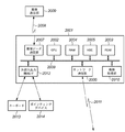
図1は本発明の実施形態1の画像処理システムの全体の構成を示すブロック図である。
<Embodiment 1>
FIG. 1 is a block diagram showing the overall configuration of the image processing system according to the first embodiment of the present invention.
1001は本発明に適用される画像編集装置である。画像編集装置1001には、一般的に中央演算装置を備えたコンピュータが用いられている。
1002は本発明に適用される画像形成装置である。画像形成装置1002には、モノクロ印刷専用の装置や、カラー出力可能である装置や大容量出力が可能な装置のように様々な形態の装置が存在する。
1003は本発明に適用されるジョブモニタリング装置である。ジョブモニタリング装置1003では、画像形成装置1002に投入されたジョブの監視やジョブの優先度の変更等の操作を行うことが可能である。
1004は、画像編集装置1001と画像形成装置1002とジョブモニタリング装置1003を相互に接続するためのネットワークである。
A
次に、画像編集装置1001の構成について、図2を用いて説明する。
Next, the configuration of the
図2は本発明の実施形態1の画像編集装置の構成を示すブロック図である。 FIG. 2 is a block diagram showing the configuration of the image editing apparatus according to the first embodiment of the present invention.
2001は、画像編集装置1001のコントローラである。2002は、画像編集装置1001全体を制御するためのプログラムを動作させるためのCPUである。2003は、画像編集装置1001を起動させるための各種プログラムが格納されているROMである。
2004は、画像編集装置1001を制御するためのプログラムを動作させるためのデータ作業領域や一時待避領域として機能するRAMである。2005は、RAM2004に展開して動作させるプログラムデータや、アプリケーションソフトのプログラムやアプリケーションソフトが必要とするデータを格納するための2次記憶装置であるハードディスクドライブ(HDD)である。
2006は、画像形成装置1002とデータの入出力処理を行うネットワーク通信部である。2007は、画像編集装置1001上で形成された画像データを画像表示部2009に送信する画像データ送信部である。
A
2008は、画像データ送信部2007から外部の画像表示部2009に、画像データを送信するためのケーブルである。2009は、画像データ送信部2008から受信した画像データを表示するための画像表示部である。
2010は、ネットワーク通信部2006から受信したデータ(例えば、ビットマップイメージデータ)に対して各種画像処理を施すための画像処理部である。画像処理部2010では、印刷用紙2ページ分のビットマップイメージデータを1ページ分のビットマップイメージデータに合成する合成機能や、ビットマップイメージデータ中に存在する不正描画部分を除去する除去機能を備えている。更に、画像処理部2010では、ビットマップイメージデータが基準方向に斜行していると判定した場合に、印刷位置を補正する補正機能を備えている。このように、画像処理部2010では、ビットマップイメージデータをデジタル的に編集する各種画像処理機能を備えている。
An
2011は、画像データを外部装置から受信し、印刷データを外部装置に送信するためのネットワークケーブルである。ネットワークケーブル2011は、ネットワーク通信部2006に接続されている。2012は、外部入出力機器とのインタフェースとなる外部入出力機器I/Fである。外部入出力機器I/F2012には、例えば、キーボード2013及びポインティングデバイス2014が接続される。
尚、ジョブモニタリング装置1003も、画像編集装置1001と同様のハードウェア構成を有する。
Note that the
次に、画像形成装置1002の構成について、図3を用いて説明する。
Next, the configuration of the
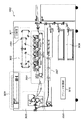
図3は本発明の実施形態1の画像形成装置の構成を示す断面図である。 FIG. 3 is a cross-sectional view showing the configuration of the image forming apparatus according to the first embodiment of the present invention.
画像形成装置1002は、主に、スキャナ部3001、レーザ露光部3002、作像部3004、定着部3005、給紙/搬送部3006及び、これらを制御するプリンタ制御部3010から構成される。
The
スキャナ部3001は、原稿台に置かれた原稿に対して、照明を当てて原稿画像を光学的に読み取り、その像を電気信号に変換して画像データを作成する工程の処理を行う。レーザ露光部3002は、画像データに応じて変調されたレーザ光等の光線を、等角速度で回転する回転多面鏡(ポリゴンミラー)3009に入射させ、反射走査光として感光ドラム3003に照射する。
The
作像部3004は、一連の電子写真プロセスの現像ユニット(現像ステーション)を4連持つことで実現されている。この一連の電子写真プロセスは、感光ドラム3003を回転駆動し、帯電器によって帯電させ、レーザ露光部3002によって感光ドラム3003上に形成された潜像をトナーによって現像するプロセスがある。また、そのトナー像を印刷用紙(シートとも言う)に転写し、その際に転写されずに感光ドラム3003上に残った微小トナーを回収する等のプロセスがある。
The
シアン(C)、マゼンタ(M)、イエロー(Y)、ブラック(K)の順に並べられた4連の現像ユニットは、シアン用の現像ユニットの作像開始から所定時間経過後に、マゼンタ、イエロー、ブラック用の現像ユニットによる作像動作を順次実行していく。このタイミング制御によって、シート上に色ずれのない、フルカラートナー像が転写される。 Four series of development units arranged in the order of cyan (C), magenta (M), yellow (Y), and black (K) are magenta, yellow, The image forming operation by the black developing unit is sequentially executed. By this timing control, a full color toner image without color misregistration is transferred onto the sheet.
定着部3005は、ローラやベルトの組み合わせによって構成され、ハロゲンヒータなどの熱源を内蔵し、作像部3004によってトナー像が転写されたシート上のトナーを、熱と圧力によって溶解、定着させる。
The
給紙/搬送部3006は、シートカセットやペーパーデッキに代表されるシート収納庫3008を一つ以上持っている。給紙/搬送部3008は、プリンタ制御部3010の指示に応じて、シート収納庫3008に収納された複数のシートの中から一枚分離し、作像部3004・定着部3005へ搬送する。搬送されたシートは、前述の現像ステーションによって、各色のトナー像が転写され、最終的にフルカラートナー像がシート上に形成される。また、シートの両面に画像形成する場合は、定着部3005を通過したシートを再度作像部3004へ搬送する両面搬送経路3007を通るように制御する。
The sheet feeding / conveying
プリンタ制御部3010は、画像形成装置1002全体を制御する制御部3011と通信して、その指示に応じて制御を実行する。これに加えて、スキャナ部3002、レーザ露光部3002、作像部3004、定着部3005、給紙/搬送部3006の各部の状態を管理しながら、全体が調和を保って円滑に動作できるよう指示を行う。
The
次に、画像形成装置1002のメインコントローラ(制御部3001)の構成について、図4を用いて説明する。
Next, the configuration of the main controller (control unit 3001) of the
図4は本発明の実施形態1の画像形成装置のメインコントローラの構成を示すブロック図である。 FIG. 4 is a block diagram showing the configuration of the main controller of the image forming apparatus according to the first embodiment of the present invention.
4001は、画像形成装置1002のメインコントローラである。4002は、画像形成装置1002の操作を行うための操作部である。この操作部4002は、例えば、表示部と入力部からなるタッチパネルで構成される。4003は、外部機器とネットワークによって接続を行うためのネットワークケーブルである。
4004は、外部機器と電話回線によって接続を行うための回線ケーブルである。4005は、メインコントローラ4001全体を制御するためのプログラムを動作させるCPUである。4006は、CPU4005上で動作するプログラムによって管理されるRAMである。RAM4006は、外部から受信したデータを一時的に蓄えるための受信バッファやRIP4021によってラスタライズされた画像データを一時的に蓄えるための画像データバッファ等の目的で使用される。
4007は、操作部4002とメインコントローラ4001を接続するための操作部インタフェース(I/F)である。4008は、メインコントローラ4001とネットワークを接続するためのネットワークインタフェース(I/F)である。4009は、メインコントローラ4001と電話回線を接続するためのモデムである。
4010は、CPU4005上で動作するプログラムやデータ等を格納するためのROMである。4011は、様々なデータを長期的に保存することが可能な不揮発性の記憶装置であるハードディスクドライブ(HDD)である。4012は、CPUバスである。
4024は画像処理を行うためのハードウェア群に接続されたイメージバス4024である。
4013は、CPUバス4012とイメージバス4024を接続するためのイメージバスインタフェース(I/F)である。4021は、外部から入力される画像記述データをビットマップイメージデータに変換する機能を有するラスタイメージプロセッサ(RIP)である。
4014は、画像転送バス4018によって、RIP4021とイメージバス4024を接続するためのRIPインタフェース(I/F)である。4015は、データを圧縮するためのデータ圧縮部である。4022は、スキャナであり、これは、図3のスキャン部3001に対応する。4023は、プリンタ部であり、これは、図3のレーザ露光部3002、作像部3004、定着部3005、給紙/搬送部3006に対応する。
4016は、データバス4019及び4040それぞれによってスキャナ4022及びプリンタ部4023をイメージバス4024に接続するためのデバイスインタフェース(I/F)である。
4017は、スキャナ4022及びRIP4021によって生成されたビットマップイメージデータに各種画像処理を施すための画像処理部である。画像処理部4017は、印刷用紙2ページ分のビットマップイメージデータを1ページ分のビットマップイメージデータに合成する合成機能や、スキャナ4022で原稿を読み取る際に埃等の混入によって発生する不正描画部分を除去する除去機能を備える。更には、画像処理部4017は、スキャナ4022に原稿を読み取らせる場合に斜行して読み取られてしまった場合の印刷位置を補正するための補正機能を備えている。このように、画像処理部4017では、ビットマップイメージデータをデジタル的に編集する各種画像処理機能を備えている。
次に、画像形成装置1002に装着可能な後処理装置の一例として、フィニッシャ部の構成について、図5を用いて説明する。
Next, as an example of a post-processing apparatus that can be attached to the
図5は本発明の実施形態1の画像形成装置に装着可能なフィニッシャ部の構成を示す断面図である。 FIG. 5 is a cross-sectional view illustrating a configuration of a finisher unit that can be attached to the image forming apparatus according to the first exemplary embodiment of the present invention.
フィニッシャ5001は、メインコントローラ4001からの指示により処理の開始、中断、終了等の各種制御が行われる。
The
給紙機構5002に配置されたシートは、フィニッシャ5001の処理が開始されるとフィニッシャ5001の内部に入る。フィニッシャ5001の内部には、サンプルトレイ5003及びスタックトレイ5004があり、ジョブの種類や排出されるシートの枚数に応じて切り替えて排出される。
The sheet placed in the
尚、サンプルトレイとは、印刷の途中で印刷結果を確認するために設けられたトレイである。例えば、ユーザが印刷中に排出先をサンプルトレイに変更することを指示すると、印刷結果の排出先が一時的にサンプルトレイへと変更される。ユーザは、そのサンプルトレイへ排出された印刷物を確認して、このまま印刷を継続するか、印刷を中止して印刷データを変更するかを決定する。 The sample tray is a tray provided for confirming the printing result during printing. For example, when the user instructs to change the discharge destination to the sample tray during printing, the discharge destination of the print result is temporarily changed to the sample tray. The user confirms the printed matter discharged to the sample tray and determines whether to continue printing as it is or to cancel printing and change the print data.
シートをソートして排紙するための代表的なソート方式(ソーティング)には2通りある。1つは、複数の排紙ビンに対して、各排紙ビンにシートを振り分けるビンソート方式がある。もう1つは、電子ソート機能とビン(または、トレイ)を、フィニッシャ5001からシートを排紙する方向に対して奥手前方向にシフトしてジョブ毎にシートを振り分けるシフトソート方式がある。
There are two typical sorting methods (sorting) for sorting and discharging sheets. One is a bin sorting method in which sheets are distributed to each paper discharge bin for a plurality of paper discharge bins. The other is a shift sort method in which an electronic sort function and a bin (or tray) are shifted in the frontward direction with respect to the direction in which the sheet is discharged from the
電子ソート機能は、コレートと呼ばれる。これは、メインコントローラ4001に大容量メモリが搭載されて、これをバッファメモリとして利用できる場合に、バッファリングしたページ順と排出順を変更する機能(コレート機能)である。このコレート機能を用いることで、電子ソーティングの機能もサポートできる。
The electronic sort function is called collate. This is a function (collating function) that changes the buffered page order and discharge order when a large-capacity memory is mounted on the
また、グループ機能というものがあり、これは、ソーティングがジョブ毎にシートを振り分ける機能であるのに対し、ページ毎にシートを仕分けする機能である。 There is also a group function, which is a function for sorting sheets for each job, whereas sorting is a function for sorting sheets for each job.
さらに、出力すべきジョブに対してステープルモードが設定されている場合には、スタックトレイ5004に排出するよう制御する。但し、その際には、シートがスタックトレイ5004に排出される前に、シートをジョブ毎にフィニッシャ5001内部の処理トレイに順次蓄えておき、その処理トレイ上にてステープラにてバインドする。そして、その上で、スタックトレイ5004へ、バインドされたシート束を束排出する。
Further, when the staple mode is set for the job to be output, control is performed so that the sheet is discharged onto the
その他、上記2つのトレイに至るまでに、紙をZ字状に折るためのZ折り機5005、ファイル用の2つ(または3つ)の穴開けを行うパンチャ5006があり、ジョブの種類に応じてそれぞれの処理を行う。
In addition to the above two trays, there are a Z-
例えば、出力すべきジョブに対するシート処理に関する設定として、ユーザにより操作部4002を介してZ折り処理設定がなされた場合には、そのジョブに対するシートに対してZ折り機5005により折り処理を実行させる。そして、その上で、機内を通過させて、スタックトレイ5004及びサンプルトレイ5003等の排出トレイに排紙するよう制御する。
For example, when the user sets the Z-folding process via the
また、出力すべきジョブに対するシート処理に関する設定として、ユーザにより操作部4002を介してパンチ処理設定がなされた場合には、そのジョブに対するシートに対してパンチャ5006によるパンチ処理を実行させる。そして、その上で、機内を通過させて、スタックトレイ5004及びサンプルトレイ5003等の排出トレイに排紙するよう制御する。
Further, when the user sets punch processing via the
さらに、サドルステッチャ5007は、シートの中央部分を2ヶ所バインドした後に、シートの中央部分をローラに噛ませることによりシートを半折りし、パンフレットのようなブックレットを作成する処理(製本処理)を行う。サドルステッチャ5007で製本されたシートは、ブックレットトレイ5008に排出される。サドルステッチャ5007による製本処理等のシート処理動作の実行可否も、上述の如く、出力すべきジョブに対してユーザにより設定されたシート処理設定に基づくものである。
Further, the
また、インサータ5009は、インサートトレイ5010にセットされたシートを画像形成装置1002へ通さずにスタックトレイ5004及びサンプルトレイ5003等の排出トレイのいずれかに送るためのものである。これによって、フィニッシャ5001に送り込まれるシート(画像形成装置1002で印刷され、排出されたシート)とシートの間にインサータ5009にセットされたシートをインサート(中差し)することができる。インサータ5009のインサートトレイ5010には、ユーザによりフェイスアップの状態でセットされるものとし、ピックアップローラにより最上部のシートから順に給送する。
The
従って、インサータ5009からのシートは、そのままスタックトレイ5004またはサンプルトレイ5003へ搬送することによりフェイスダウン状態で排出される。サドルステッチャ5007へ送るときには、一度パンチャ側へ送り込んだ後、スイッチバックさせて送り込むことによりフェースの向きを合わせる。尚、インサータ5009によるシート挿入処理等のシート処理動作の実行可否も、上述の如く、出力すべきジョブに対してユーザにより設定されたシート処理設定に基づくものである。
Accordingly, the sheet from the
次に、トリマ5011(断裁機)について説明する。 Next, the trimmer 5011 (cutting machine) will be described.
サドルステッチャ5007において、ブックレット(中綴じの小冊子)にされた出力は、このトリマ5011に入ってくる。その際に、まず、ブックレットの出力は、ローラで予め決められた長さ分だけ紙送りされ、カッタ部5012にて予め決められた長さだけ切断される。これにより、ブックレット内の複数ページ間でばらばらになっていた端部がきれいに揃えられることとなる。そして、ブックレットホールド部5013に格納される。尚、トリマ5011による断裁処理等のシート処理動作の実行可否も、上述の如く、出力すべきジョブに対してユーザにより設定されたシート処理設定に基づくものである。
In the
次に、画像形成装置1002に装着可能なな後処理装置の一例として、大容量スタッカ装置の構成について、図6を用いて説明する。
Next, as an example of a post-processing apparatus that can be attached to the
図6は本発明の実施形態1の画像形成装置に装着可能な大容量スタッカ装置の構成を示す断面図である。 FIG. 6 is a cross-sectional view showing a configuration of a large-capacity stacker apparatus that can be mounted on the image forming apparatus of Embodiment 1 of the present invention.
大容量スタッカ6001は、メインコントローラ4001からの指示により処理の開始、中断、終了等の制御が行われる。
The large-
給紙機構6002に配置されたシートは、大容量スタッカ6001の処理が開始されると大容量スタッカ6001の内部に入る。大容量スタッカ6001の内部には、サンプルトレイ6003及びスタックトレイ6004があり、ジョブの種類や排出されるシートの枚数に応じて切り替えて排出される。
The sheet placed in the
スタックトレイ6004では、このスタックトレイ6004に排紙中は排紙されたシートを取り除くことができない。そのため、スタックトレイ6004から印刷されたシートを取り出す際には、このスタックトレイ6004への出力を中断する必要がある。
In the
次に、画像編集装置1001で動作する画像編集機能を備えたアプリケーションソフトウェアの操作画面について、図7を用いて説明する。
Next, an operation screen of application software having an image editing function that operates on the
図7は本発明の実施形態1の画像編集装置上で動作する画像編集機能を備えたアプリケーションソフトウェアの操作画面を示す模式図である。 FIG. 7 is a schematic diagram showing an operation screen of application software having an image editing function that operates on the image editing apparatus according to the first embodiment of the present invention.
7001は、画像編集機能を備えたアプリケーションソフトウェアによって生成される操作画面である。7002は、画像編集領域である。画像編集を行うオペレータは、画像編集領域7002で示される画像に対して各種画像編集処理を指示することが可能である。画像編集処理の処理内容の指定は、各種コントロール7004(メニュー、ボタン等)を用いて行うことができる。
7003は、サムネイル表示部である。サムネイル表示部7003は、アプリケーションソフトウェア上で作成されたページのサムネイル画像を表示させる部分である。このサムネイル表示部7003は、スクロールバー7003aの操作により、ジョブに含まれる全てのページのサムネイル画像を閲覧することが可能である。
次に、画像編集装置1001上で動作するプリンタドライバソフトウェアの操作画面について、図8を用いて説明する。
Next, an operation screen of printer driver software operating on the
図8は本発明の実施形態1の画像編集装置上で動作するプリンタドライバソフトウェアの操作画面を示す概観図である。 FIG. 8 is a general view showing an operation screen of printer driver software operating on the image editing apparatus according to the first embodiment of the present invention.
8001はプリンタドライバソフトウェアによって生成される操作画面である。
画像編集装置1001上で動作するアプリケーションソフトウェア上で処理されている画像をジョブとして画像形成装置1002に送信する場合に、そのジョブに係る各種印刷設定をこの操作画面8001を介して行うことができる。
When an image processed on application software running on the
8002は、ジョブの各種設定を行う操作部である。操作部8002では、印刷文書の印刷ページ数や印刷部数、さらに詳細設定画面に移行して用紙種(印刷媒体タイプ)や面付けのレイアウトやカラーの画像処理方法等の各種印刷設定を行うことが可能である。
8003は、ジョブの送信(印刷)を指示するためのボタンである。操作者は、ボタン8003を押下することにより、ジョブを画像形成装置1002へ送信(印刷)することができる。
8004は、ジョブの印刷優先度を指示するためのテキストボックスである。画像編集装置1001上で画像の印刷指示を行う操作者は、優先度を指示するためのテキストボックス8004によって印刷処理の優先度を指示することができる。また、単に先行しているジョブに対して割り込んで印刷処理を実行するための割込み属性が指示できても良い。一方、画像形成装置1002では、この印刷優先度に応じて受信したジョブの印刷順番の制御を行う。
次に、ジョブモニタリング装置1003上で動作するジョブモニタリングソフトウェアについて、図9を用いて説明する。
Next, job monitoring software operating on the
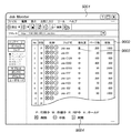
図9は本発明の実施形態1のジョブモニタリング装置上で動作するジョブモニタリングソフトウェアの概要を示す概観図である。 FIG. 9 is an overview diagram showing an outline of job monitoring software operating on the job monitoring apparatus according to the first embodiment of the present invention.
ジョブモニタリングソフトウェアによって生成される操作画面9001では、画像形成装置1002上のジョブの状況を表示したり、そのジョブに対して削除や中断や、中断されているジョブの再開等の各種指示を行うことが可能である。
On the
9002は、画像形成装置1002上で動作しているジョブの一覧表示部である。画像形成装置1002にジョブが投入されると、一覧表示部9002にそのジョブが表示される。また、処理が終了したジョブは、一覧表示部9002上から削除される。
9003は、一覧表示部9002上で表示されているジョブの印刷の優先度を示す優先度表示部である。優先度表示部9003には、図8の操作画面8001のテキストボックス8004で指示されたジョブに付与された優先度情報が表示される。
9004は、一覧表示部9002上で表示されているジョブに対してジョブの削除や中断や中断されているジョブの再開を指示するための操作部である。
次に、印刷データの処理例について、図10及び図11を用いて説明する。 Next, an example of print data processing will be described with reference to FIGS.
図10及び図11は、本発明の実施形態1の画像形成装置が、先行ジョブに含まれる印刷データによって印刷用紙上に印刷を行わない部分(空き領域)を検出する場合の検出例を示す図である。 FIGS. 10 and 11 are diagrams illustrating a detection example when the image forming apparatus according to the first exemplary embodiment of the present invention detects a portion (empty area) where printing is not performed on a print sheet based on print data included in a preceding job. It is.
10001及び11001は、印刷用紙を示している。実施形態1では、印刷ジョブとして、縦方向が297mm、横方向が210mmのサイズの印刷用紙10001が指定された場合を例に挙げて説明する。なお、画像形成装置1002は、用紙種類ごとの縦方向および横方向サイズを、例えば、RAM4006等に保持している。
例えば、画像形成装置1002は、「A4サイズは、縦方向が297mm、横方向が210mm」、「A5サイズは、縦方向が210mm、横方向が148.5mm」という情報を保持している。よって、印刷ジョブとして「A4」、「A5」等のように具体的なサイズが指定されていなくても、画像形成装置は印刷用紙サイズを算出できる。つまり、画像形成装置1002は、図23に示すような画像形成装置に収納されている複数種類のサイズの印刷媒体情報を記憶している。尚、図23では、印刷用紙のサイズに関する情報(印刷媒体情報2301)が保持されているが、その他の情報が保持されていても良い。
For example, the
10002及び11002は、印刷用紙10001に印刷される先行ジョブの画像領域である。ここでは、画像領域10002及び11002(図11)の縦方向(長手方向)のサイズが210mm、横方向(短手方向)のサイズが170mmである場合を例に挙げて説明する。ここで、画像領域とは、先行ジョブで印刷用紙上に印刷する画像そのもの、あるいはその画像と、その画像の周辺に確保する余白画像の両方を含む領域を意味するものとする。
図10と図11は、余白画像を必要としない場合と、必要とする場合の両方の場合を想定したものである。また、画像領域のサイズについては、画像形成装置1002が、受信したジョブを解析することにより算出できる。具体的には、画像形成装置1002が受信するジョブは、画像形成装置が解釈可能なページ記述言語で記述されている。画像形成装置1002は、受信したページ記述言語を解析することにより、受信したジョブに基づいて記録すべき画像のサイズを算出できる。
FIG. 10 and FIG. 11 assume both the case where the margin image is not required and the case where it is required. Further, the size of the image area can be calculated by the
実施形態1では、画像領域10002に含まれる画像を印刷用紙10001に印刷する際には、印刷用紙10001の左上を原点にして配置するものとする。即ち、印刷用紙10001の左上と、画像領域10002の左上(あるいは、画像領域10002に確保された余白領域の左上)が一致するように配置される。
In the first embodiment, when an image included in the
10003及び10004は、印刷用紙10001に画像領域10002上の画像を印刷して出力した後に、印刷用紙10001の余分な領域を切り取るための縦方向と横方向の断裁位置である。画像形成装置1002による印刷後に、フィニッシャ等の後処理装置を用いて断裁位置10003と10004の情報に従って断裁処理が行われる。
11003は、処理対象としている印刷ジョブに含まれる印刷データを、印刷用紙11001に配置した結果生じる空き領域である。
空き領域11003は、印刷用紙11001の縦方向のサイズから画像領域1102の縦方向のサイズを引いたサイズと、印刷用紙11001の横方向のサイズから画像領域1102の横方向のサイズを引いたサイズから算出される。実施形態1では、上述した算出方法により算出された縦方向:87mm(297−210mm)と、横方向:40mm(210−170mm)により、図11に示す空き領域11003を算出する(導き出す)ことができる。
The
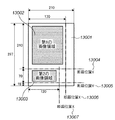
図12は本発明の実施形態1の画像形成装置において、図10及び図11を用いて説明した印刷用紙の空き領域に、画像形成装置1002に予め保持されている画像を印刷する場合の印刷位置を説明するための図である。
FIG. 12 shows a printing position when printing an image previously held in the
12001は、印刷用紙である。印刷用紙12001のサイズは、図10及び図11で説明されている印刷用紙のサイズに準拠する。12002は、先行ジョブによって印刷データが描画されない空き領域である。領域12002のサイズ及び配置は、図10及び図11で説明されている画像領域のサイズ及び配置に準拠する。
12003は、先行ジョブと結合されるジョブの印刷データによって描画される画像である。実施形態1では、縦方向のサイズが70mm、横方向のサイズが120mmの画像12003を用いて説明を行う。
12004は、印刷用紙12001の右側の空き領域と印刷用紙12001の下側の空き領域における共通の空き領域である。
12005は、印刷用紙12001の右側の空き領域の一部分である。印刷用紙12001の右側の空き領域は、空き領域12005と空き領域12004を併せた領域(以下、右側の空き領域)となる。
12006は、印刷用紙12001の下側の空き領域の一部分である。印刷用紙12001の下側の空き領域は、空き領域12006と空き領域12004を併せた領域(以下、下側の空き領域)となる。
空き領域12004、12005、12006に画像12003を配置する際に、画像12003の縦方向のサイズと右側及び下側の空き領域の縦方向のサイズ、画像12003の横方向のサイズと右側及び下側の空き領域の横方向のサイズを比較する。そして、両者の比較結果において、右側もしくは下側の空き領域より画像12003のサイズが小さいと判定された場合、その空き領域に画像12003を配置するように画像位置が決定される。
When placing the
つまり、図12では、画像12003の横方向のサイズが、右側空き領域の横方向のサイズよりも大きいため、画像12003は、右側空き領域には配置できないと判定される。一方、画像12003の横方向サイズ(120mm)および縦方向サイズ(70mm)は、下側空き領域の横方向サイズ(170mm)、および、縦方向サイズ(87mm)に収る。そのため、画像形成装置1002は、画像12003を下側空き領域に配置可能と判断する。
That is, in FIG. 12, since the horizontal size of the
図13は本発明の実施形態1の画像形成装置1002において、先行して処理されている第1のジョブによる第1の画像と、第1のジョブとは別の第2のジョブによる第2の画像を印刷する際の印刷用紙と画像の位置の関係を示す図である。
FIG. 13 illustrates a first image by a first job processed in advance and a second job by a second job different from the first job in the
13001は、印刷用紙である。印刷用紙13001のサイズは、図10〜図12で説明されている印刷用紙のサイズに準拠する。
13001 is a print sheet. The size of the
13002は、先行する第1のジョブによる第1の画像領域である。第1の画像領域13002のサイズ及び配置は、図10及び図11で説明されている画像領域のサイズ及び配置に準拠する。
13003は、第1のジョブとは別の第2のジョブによる第2の画像である。第2の画像13003のサイズ及び配置は、図12で説明されている画像領域のサイズ及び配置に準拠する。
13003 is a second image by a second job different from the first job. The size and arrangement of the
13004及び13006は、第1のジョブにおける最終印刷物を形成するために印刷用紙の一部を切り落とすための縦方向及び横方向の断裁位置である。
13005及び13007は、第2のジョブにおける最終印刷物を形成するために用紙の一部を切り落とすための縦方向及び横方向の断裁位置である。
図14は本発明の実施形態1の画像形成装置において、複数のジョブを受信した場合に、ジョブを管理するためのジョブキューの概略を示す図である。 FIG. 14 is a diagram showing an outline of a job queue for managing jobs when a plurality of jobs are received in the image forming apparatus according to the first embodiment of the present invention.
14001は、ジョブキューである。画像形成装置1002では、外部機器(例えば、画像編集装置1001)からジョブを受信した場合、ジョブキュー14001へジョブを格納して、画像形成装置1002が印刷可能状態に移行するまで保持される。このジョブキュー14001は、例えば、RAM4006(図4)上で確保される。
14002〜14004は、ジョブを模式的に示しているものである。特に、14002は、印刷状態に移行しているジョブである。14003は、ジョブキュー1001において待機しているジョブである。14004は、外部機器から画像形成装置1002へ投入されようとしているジョブである。
ジョブキュー14001は、FIFO形式の構造となっているため、画像形成装置1002に投入されたジョブは、投入された順番に従って印刷処理される。但し、ジョブの属性として印刷優先度の高低を識別することが可能であり、印刷優先度の高いジョブを受信した場合は、優先度の高い印刷ジョブが優先的に処理される。
Since the
図15は本発明の実施形態1の画像形成装置において、第1のジョブを印刷中に、印刷優先度の高い第2のジョブが投入された際のジョブの出力結果を示す図である。 FIG. 15 is a diagram illustrating a job output result when a second job having a high print priority is input during printing of the first job in the image forming apparatus according to the first exemplary embodiment of the present invention.
15001は、先行して処理されている第1のジョブにより印刷される画像領域である。15002は、第1のジョブの処理中に投入された優先度の高い第2のジョブにより印刷される画像領域である。特に、ここでは、第1のジョブの2460ページ目から2959ページ目に対して、第2のジョブの印刷が並行して印刷される場合を示している。
次に、実施形態1の画像形成装置1002の印刷制御処理について、図16を用いて説明する。
Next, print control processing of the
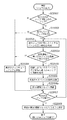
図16は本発明の実施形態1の画像形成装置の印刷制御処理を示すためのフローチャートである。尚、本フローチャートにおける各ステップは、画像形成装置の制御部3001によって実行される。
FIG. 16 is a flowchart for illustrating print control processing of the image forming apparatus according to the first embodiment of the present invention. Each step in this flowchart is executed by the
以下、図16のフロチャートに従って、実施形態1における画像形成装置1002の印刷制御手順を説明する。
Hereinafter, the printing control procedure of the
ステップS16001で、画像形成装置1002は、外部機器からジョブを受信した際に、その受信したジョブが優先度の高いジョブ(以下、割り込みジョブ)であるか否かを判定する。上述したようにジョブには、ジョブの属性として印刷優先度の高低を識別するための情報が含まれている。画像形成装置1002は、ジョブに含まれる情報を解析することで優先度の高いジョブを判定することができる。
In step S 16001, when the
尚、画像形成装置1002は、先行ジョブの処理中に入力された割り込みジョブに付加されている印刷優先度が、先行ジョブに付加されている印刷優先度よりも高い場合に、S16003、S16004の処理を実行する。割り込みジョブには、属性として割り込んで処理すべきことを示す属性が含まれていても良い。
Note that the
受信したジョブが割り込みジョブでない場合(ステップS16001でNO)、ステップS16008へ進み、画像形成装置1002は、その受信したジョブをジョブキュー14001へ格納(登録)して処理を終了する。一方、受信したジョブが割り込みジョブである場合(ステップS16001でYES)、ステップS16002へ進む。
If the received job is not an interrupt job (NO in step S 16001), the process advances to step S 16008, and the
ステップS16002で、画像形成装置1002は、印刷処理されているジョブ(以下、先行ジョブ)が存在しているか否かを判定する。即ち、図14に示すジョブ14002が存在しているか否かを判定する。
In step S 16002, the
先行ジョブが存在していない場合(ステップS16002でNO)、ステップS16008へ進み、受信したジョブを、ジョブキュー14001へ格納して処理を終了する。
If no preceding job exists (NO in step S 16002), the process advances to step S 16008, the received job is stored in the
尚、ジョブキュー14001に登録されたジョブについては、そのジョブの印刷後は、必要に応じて、後処理装置において、印刷済用紙の断裁処理がトリマ5011(図5)によって断裁処理が実行されることになる。後処理装置は、例えば、図10の構成の場合では、画像領域10002に対する印刷が完了した印刷済用紙に対して、断裁位置10003及び10004で断裁する。断裁後は、画像領域10002を含む部分印刷済用紙は、指定の排出部に排出されるとともに、それ以外の部分印刷用紙は、指定の廃棄部に廃棄されることになる。
Note that for a job registered in the
一方、先行ジョブが存在している場合(ステップS16002でYES)、ステップS16003へ進む。ステップS16003で、画像形成装置1002は、先行ジョブが印刷しようとするページの空き領域を、図10及び図11を用いて説明した方法により判別する。つまり、画像形成装置1002は、先行ジョブに割り込ませて処理すべき割り込みジョブが入力された場合、先行ジョブに基づく画像が印刷媒体上に配置されない空き領域を判別する。
On the other hand, if a preceding job exists (YES in step S 16002), the process proceeds to step S 16003. In step S <b> 16003, the
そして、ステップS16004で、図12を用いて説明した方法により、画像形成装置1002は、ステップS16003で判別された空き領域に割り込みジョブにより印刷される画像領域を配置することが可能か否かを判定する。つまり、画像形成装置1002は、S16004で判別した印刷媒体の空き領域内に、割り込みジョブに基づく画像を配置できるか否かを判定する。
In step S16004, the
ステップS16004で、画像形成装置1002が、ステップS16003で判別された空き領域に割り込みジョブにより印刷される画像領域を配置することが不可能であると判定した場合(ステップS16004でNO)、ステップS16008へ進む。そして、ステップS16008で、画像形成装置1002は、受信したジョブをジョブキュー14001へ格納して処理を終了する。
If the
ステップS16008において、画像形成装置1002は、空き領域に割り込みジョブの画像を配置不可能である場合、先行ジョブと割り込みジョブを異なる印刷媒体へ印刷するように制御する。その後、断裁機が、各印刷結果を各ジョブで指定された位置で断裁する。なお、断裁機は、画像形成装置1002に装着されていても、画像形成装置1002とは独立していても良い。
In step S16008, if the image of the interrupt job cannot be arranged in the free area, the
一方、画像形成装置1002が、ステップS16003で判別された空き領域に割り込みジョブにより印刷される画像領域を配置することが可能であると判定した場合(ステップS16004でYES)、ステップS16005へ進む。
On the other hand, if the
ステップS16005で、画像形成装置1002は、画像合成機能を備える画像処理部4017を使用して、ステップS16003で判別された空き領域に割り込みジョブの画像を合成する画像合成処理を実行する。ステップS16006で、画像形成装置1002は、ステップS16005で先行ジョブと割り込みジョブの画像が合成されたページをプリンタ部4023へ送信して印刷処理を実行する。
In step S16005, the
つまり、画像形成装置1002は、S16004の判定の結果、印刷媒体上の空き領域に割り込みジョブの画像を配置可能である場合、印刷媒体上に先行ジョブの画像、および割り込みジョブの画像が形成されるように印刷を制御する。
That is, if the
ステップS16007で、割り込みジョブで印刷されるべき画像が全て印刷されたか否かを判定する。割り込みジョブで印刷されるべき画像が全て印刷された場合(ステップS16007でYES)、本割り込みジョブによる印刷処理を終了し、先行ジョブの処理のみを継続して実行する。一方、割り込みジョブで印刷されるべき画像が全て印刷されていない場合(ステップS16007でNO)、ステップS16003へ戻り、先行しているジョブが出力する印刷用紙に割り込みジョブを印刷するための処理を繰り返して実行する。 In step S16007, it is determined whether all images to be printed in the interrupt job have been printed. If all the images to be printed by the interrupt job have been printed (YES in step S16007), the print processing by this interrupt job is terminated, and only the processing of the preceding job is continued. On the other hand, if all the images to be printed in the interrupt job are not printed (NO in step S16007), the process returns to step S16003, and the process for printing the interrupt job on the printing paper output by the preceding job is repeated. And execute.
以上説明したように、実施形態1によれば、先行ジョブの印刷処理が行われている最中に印刷優先度の高いジョブが投入された場合でも、先行ジョブの印刷スループットの低下を発生させることなく優先度の高いジョブの印刷処理を実行することが可能となる。 As described above, according to the first embodiment, even when a job having a high print priority is input while the print processing of the preceding job is being performed, the print throughput of the preceding job is reduced. Therefore, it is possible to execute print processing for a job having a high priority.
このように、画像形成装置における印刷処理中に、印刷優先度の高い新たなジョブが投入された場合においても、先行ジョブの印刷処理を継続すると共に優先度の高い後続のジョブの印刷処理を実行することが可能となる。 As described above, even when a new job having a high print priority is input during the printing process in the image forming apparatus, the printing process of the preceding job is continued and the printing process of the subsequent job having a high priority is executed. It becomes possible to do.
即ち、従来技術における不具合点であった、画像形成装置における印刷処理中に印刷優先度の高い新たなジョブが投入された場合に、先行ジョブの印刷処理に要する時間が増加してしまうという問題を回避することが可能となる。 That is, when a new job having a high print priority is input during the printing process in the image forming apparatus, which is a problem in the conventional technology, the time required for the printing process of the preceding job increases. It can be avoided.
<実施形態2>
図1〜図16及び図17、図18を用いて、実施形態2を説明する。実施形態1では、画像形成装置1002が、出力時に使用される印刷用紙のサイズを変更することなく、先行ジョブと割り込みジョブの合成印刷を行う構成について説明した。ここで、画像形成装置1002は、通常、複数種類のサイズの印刷用紙をシート収納庫に収容していて、これを適宜選択して使用することが可能である。そのため、先行ジョブの印刷用紙に使用していた印刷用紙に、先行ジョブと割り込みジョブの合成印刷が不可能な場合でも、出力すべき印刷用紙を大判サイズへと変更することにより、合成印刷が可能な状況が存在し得る。
<
The second embodiment will be described with reference to FIGS. 1 to 16, 17, and 18. In the first exemplary embodiment, the configuration in which the
そこで、このような場合には、合成印刷をその大判の印刷用紙に印刷した上で、カッティング機能を有する後処理装置を用いて、その印刷用紙を断裁することで各ジョブの印刷結果を得ることが可能となる。なお、この後処理装置は、印刷装置に装着されていても、単体であっても構わない。 Therefore, in such a case, after printing composite printing on the large format printing paper, a post-processing device having a cutting function is used to cut the printing paper to obtain the print result of each job. Is possible. The post-processing apparatus may be mounted on the printing apparatus or may be a single unit.
以下、実施形態2では、このような構成について説明する。
Hereinafter, in
尚、図1〜図16における処理手順は、実施形態1で説明した処理手順に準拠する。 Note that the processing procedures in FIGS. 1 to 16 conform to the processing procedures described in the first embodiment.
図17は本発明の実施形態2の画像形成装置において、第1のジョブを印刷中に、印刷優先度の高い第2のジョブが投入された際のジョブの出力結果を示す図である。 FIG. 17 is a diagram illustrating a job output result when a second job having a high print priority is input during printing of the first job in the image forming apparatus according to the second exemplary embodiment of the present invention.
17001は、先行して処理されている第1のジョブにより印刷される画像領域である。17002は、第1のジョブの処理中に投入された優先度の高い第2のジョブにより印刷される画像領域である。
実施形態2では、第2のジョブを第1のジョブと合成して印刷する印刷用紙17003のサイズは、合成前の第1のジョブを印刷する印刷用紙17004のサイズと異なっている。また、ここでは、第1のジョブの2460ページ目から2959ページ目までに、第2のジョブの印刷が500ページ行われている場合を示している。
In the second embodiment, the size of the
次に、実施形態2の画像形成装置1002の印刷制御処理について、図18を用いて説明する。
Next, print control processing of the
図18は本発明の実施形態2の画像形成装置の印刷制御処理を示すフロチャートである。 FIG. 18 is a flowchart showing print control processing of the image forming apparatus according to the second embodiment of the present invention.
以下、図18のフロチャートに従って、実施形態2における画像形成装置1002の印刷制御手順を説明する。
Hereinafter, the print control procedure of the
尚、図18で、ステップS18001〜ステップS18004、ステップS18005〜ステップS18008は、それぞれ実施形態1の図16のステップS16001〜ステップS16004、ステップS16005〜ステップS16008に対応する。従って、その処理の詳細については、相違点のみを説明する。また、図18では、図16に対し、ステップS18004aの処理が追加されている。 In FIG. 18, steps S18001 to S18004 and steps S18005 to S18008 correspond to steps S16001 to S16004 and steps S16005 to S16008 in FIG. 16 of the first embodiment, respectively. Therefore, only the differences will be described in detail for the processing. In FIG. 18, the process of step S18004a is added to FIG. 16.
ステップS18004で、画像形成装置1002が、ステップS18003で判別された空き領域に割り込みジョブにより印刷される画像領域を配置することが可能であると判断した場合(ステップS18004でYES)、ステップS18005へ進む。
If the
一方、画像形成装置1002が、ステップS18003で判別された空き領域に割り込みジョブにより印刷される画像領域を配置することが不可能であると判断した場合(ステップS18004でNO)、ステップS18004aに進む。
On the other hand, if the
ステップS18004aで、画像形成装置1002は、図13で示す第1のジョブと第2のジョブによる画像を印刷することが可能な印刷用紙の選択処理を実行する。換言すれば、第1のジョブと第2のジョブによる画像の画像領域を包含することが可能なサイズの印刷用紙を選択する。
In step S18004a, the
尚、画像形成装置1002は、上述したように画像形成装置にセットされている各印刷用紙の印刷媒体情報を保持している。画像形成装置1002は、第1のジョブに基づく画像のサイズと第2のジョブに基づく画像のサイズの合計サイズを算出する。そして、画像形成装置1002は、ステップS18004aにおいて第1のジョブと第2のジョブの合成により得られる画像領域の合計サイズを包含可能な印刷用紙を選択する。但し、選択可能なサイズの印刷用紙が、画像形成装置1002内のシート収納庫内で収納されていない場合には、第1のジョブ及び第2のジョブはそれぞれ別のジョブとして、ステップS18008で、ジョブキュー14001に登録する。
Note that the
ステップS18005で、画像形成装置1002は、画像合成機能を備える画像処理装置4017を使用して、先行ジョブによる画像と割り込みジョブによる画像を合成する画像合成処理を実行する。ステップS18006で、画像形成装置1002は、ステップS18005で先行ジョブと割り込みジョブを合成した画像をプリンタ部4023へ送信して印刷処理を実行する。尚、ここで、ステップS18004aの処理が実行された場合には、選択された印刷用紙を用いて、印刷処理が実行されることになる。
In step S18005, the
以上説明したように、実施形態2によれば、画像形成装置が複数種類のサイズの印刷用紙を搭載している場合には、その使用可能な印刷用紙のサイズの範囲内で、できる限り先行ジョブと割り込みジョブの合成印刷を実行することができる。そのため、優先度の高い割り込みジョブも、先行ジョブも遅れることなく印刷処理を実行することが可能となる。 As described above, according to the second embodiment, when the image forming apparatus is equipped with printing papers of a plurality of types, the preceding job is as much as possible within the usable printing paper size range. And interrupt printing can be executed. For this reason, it is possible to execute the printing process without delay for both the interrupt job having a high priority and the preceding job.
尚、実施形態2では、S18004において空き領域に割り込みジョブの画像を配置することができない判定された場合(S18004−No)、先行ジョブと割り込みジョブの画像を配置可能な印刷用紙を選択している。しかし、S18004の判定処理を行わずに、S18004aの処理を実行しても良い。 In the second embodiment, if it is determined in S18004 that an interrupt job image cannot be arranged in the free area (S18004-No), a print sheet on which the preceding job and the interrupt job image can be arranged is selected. . However, the process of S18004a may be executed without performing the determination process of S18004.
つまり、画像形成装置は、投入されたジョブが割り込みジョブであると判定した場合、先行ジョブに基づく画像サイズと割り込みジョブに基づく画像サイズを算出して、両者を合計する。そして、画像形成装置は、先行ジョブに基づく画像と割り込みジョブに基づく画像を配置可能な用紙を選択する。 That is, when the image forming apparatus determines that the input job is an interrupt job, the image forming apparatus calculates the image size based on the preceding job and the image size based on the interrupt job, and adds the two. Then, the image forming apparatus selects a sheet on which an image based on the preceding job and an image based on the interrupt job can be arranged.
<実施形態3>
図1〜図16及び図19、図20を用いて、実施形態3を説明する。
<
The third embodiment will be described with reference to FIGS. 1 to 16, 19, and 20.
尚、図1〜図16における処理手順は、実施形態1で説明した処理手順に準拠する。 Note that the processing procedures in FIGS. 1 to 16 conform to the processing procedures described in the first embodiment.
実施形態3を説明するにあたり、画像形成装置1002における、印刷済用紙の排紙部(排出部)の構成について、図19を用いて説明する。
In describing the third embodiment, the configuration of a printed paper discharge unit (discharge unit) in the
図19は本発明の実施形態3の印刷済用紙の排紙部の構成を示す図である。 FIG. 19 is a diagram showing a configuration of a printed paper discharge unit according to the third embodiment of the present invention.
19002は、画像形成装置1002から出力された印刷済用紙を排紙トレイへ出力するための排紙制御部である。19003は、排紙部を構成する筐体の外部に露出して搭載されるサンプル排紙トレイである。実施形態3では、サンプル排紙トレイ19003には、割り込みジョブが合成印刷された印刷用紙が出力されるように制御される。19004は、排紙部を構成する筐体内に内蔵される大容量排紙トレイである。実施形態3では、大容量排紙トレイ19004には、先行ジョブのみの画像が印刷された用紙が出力されるように制御される。つまり、画像形成装置1002は、印刷処理が完了した印刷媒体を排出するための複数の排出部を備えており、先行ジョブの画像と割り込みジョブの画像を印刷した印刷用紙を、所定のサンプル排紙トレイへと出力する。
尚、この排紙部の指定は、処理対象の印刷ジョブあるいは、操作部4002で指定される指定情報に基づいて行う。
The paper discharge unit is designated based on a print job to be processed or designation information designated on the
次に、実施形態3の画像形成装置1002の印刷制御処理について、図20を用いて説明する。
Next, print control processing of the
図20は本発明の実施形態3の画像形成装置1002の印刷制御処理を示すフロチャートである。
FIG. 20 is a flowchart showing print control processing of the
以下、図20のフロチャートに従って、実施形態3における画像形成装置1002の印刷制御手順を説明する。
Hereinafter, the print control procedure of the
尚、図20で、ステップS20001〜ステップS20006、ステップS20007及びステップS20008は、それぞれ実施形態1の図16のステップS16001〜ステップS16006、ステップS16007及びステップS16008に対応する。従って、その処理の詳細については、相違点のみを説明する。また、図20では、図16に対し、ステップS20006aの処理が追加されている。 In FIG. 20, Step S20001 to Step S20006, Step S20007, and Step S20008 correspond to Step S16001 to Step S16006, Step S16007, and Step S16008 of FIG. Therefore, only the differences will be described in detail for the processing. In FIG. 20, the process of step S20006a is added to FIG.
ステップS20006aで、画像形成装置1002は、ステップS20006で先行ジョブと割り込みジョブを合成して出力した印刷結果を、サンプル排紙トレイ19003へ排紙するように制御する。具体的には、画像形成装置1002が、先行ジョブと割り込みジョブを合成した場合、サンプルトレイに印刷結果を排紙すべく排紙先を変更する。
In step S <b> 20006 a, the
以上説明したように、実施形態3によれば、先行ジョブが大量の出力枚数であった場合でも、大容量排紙部のドア等の開け閉めを必要とすることなく、割り込みジョブによる印刷の印刷用紙を排紙部から取り出すことが可能となる。また、合成されている印刷結果と合成されていない印刷結果を容易に分けることが可能となる。 As described above, according to the third embodiment, even when the preceding job has a large number of output sheets, printing by an interrupt job is not required without opening and closing the door of the large capacity discharge unit. The paper can be taken out from the paper discharge unit. Further, it is possible to easily separate the synthesized print result and the unsynthesized print result.
尚、実施形態3では、合成したジョブの出力先をサンプルトレイとしたが、これに限られる必要はない。つまり、画像形成装置1002は、先行ジョブの出力先として指定されていたトレイとは異なるトレイに対して合成したジョブに基づく出力結果を排出すれば、上述した効果と同様の効果を得ることが可能となる。そのため、画像形成装置1002は、先行ジョブの出力先トレイを一時的に記憶しておき、合成ジョブについては当該トレイとは異なるトレイを指定すれば良い。
In the third embodiment, the output destination of the combined job is the sample tray. However, the output destination is not limited to this. That is, the
<実施形態4>
図1〜図16及び図21、図22を用いて、実施形態4を説明する。
<
尚、図1〜図16における処理手順は、実施形態1で説明した処理手順に準拠する。 Note that the processing procedures in FIGS. 1 to 16 conform to the processing procedures described in the first embodiment.
実施形態4を説明するにあたり、画像形成装置1002における、印刷済用紙の排紙部の構成について、図21を用いて説明する。
Prior to the description of the fourth embodiment, the configuration of a printed paper discharge unit in the
図21は本発明の実施形態4の印刷済用紙の排紙部の構成を示す図である。 FIG. 21 is a diagram illustrating a configuration of a printed paper discharge unit according to the fourth embodiment of the present invention.
21002は、画像形成装置1002から出力された印刷済用紙を排紙トレイへ出力するための排紙制御部である。
21002 is a paper discharge control unit for outputting printed paper output from the
21003は、排紙部における第1の排紙トレイである。実施形態4では、第1の排紙トレイ21003には、割り込みジョブが印刷される前の先行ジョブによる印刷の印刷用紙が出力される。
21004は、排紙部における第2の排紙トレイである。実施形態4では、第2の排紙トレイ21004には、先行ジョブと割り込みジョブが合成印刷された印刷用紙が出力される。
21005は、排紙部における第3の排紙トレイである。実施形態4では、第3の排紙トレイ21005には割り込みジョブの印刷が全て完了した後の先行ジョブの印刷用紙が出力される。
次に、実施形態4の画像形成装置1002の印刷制御処理について、図22を用いて説明する。
Next, print control processing of the
図22は本発明の実施形態4の画像形成装置の印刷制御処理を示すフロチャートである。 FIG. 22 is a flowchart showing print control processing of the image forming apparatus according to the fourth embodiment of the present invention.
以下、図22のフロチャートに従って、実施形態4における画像形成装置1002の印刷制御手順を説明する。
Hereinafter, the print control procedure of the
尚、図22で、ステップS2001〜ステップS2006、ステップS2007及びステップS2008は、それぞれ実施形態1の図16のステップS1601〜ステップS1606、ステップS1607及びステップS1608に対応する。従って、その処理の詳細については、相違点のみを説明する。また、図22では、図16に対し、ステップS22006a及びステップS22009の処理が追加されている。 In FIG. 22, steps S2001 to S2006, steps S2007, and S2008 correspond to steps S1601 to S1606, steps S1607, and S1608 of FIG. 16 of the first embodiment, respectively. Therefore, only the differences will be described in detail for the processing. Further, in FIG. 22, processing of step S22006a and step S22009 is added to FIG. 16.
ステップS22006aで、画像形成装置1002は、ステップS20006で先行ジョブと割り込みジョブの画像が合成された印刷用紙を、第2の排紙トレイ21003へ排紙するように制御する。ステップS22006aの処理の一例として、画像形成装置1002は、合成前の先行ジョブの出力先トレイを一時的に記憶しておき、当該トレイとは異なるトレイを出力先として合成ジョブに基づく出力結果を排出する。
In step S22006a, the
また、ステップS22007の処理後、ステップS22009で、先行ジョブの排紙トレイを第3の排紙トレイ21004へ設定するように制御する。ステップS22009の処理の一例として、画像形成装置1002は、合成前の先行ジョブの出力先トレイと合成ジョブの出力先トレイを一時的に記憶しておき、これらのトレイとは異なるトレイを出力先として合成処理後における先行ジョブの出力結果を排出する。
Further, after the processing in step S22007, in step S22009, control is performed so that the discharge tray of the preceding job is set to the
以上説明したように、実施形態4によれば、先行ジョブと割り込みジョブによる合成印刷が行われた場合には、合成印刷前、合成印刷、合成印刷後それぞれの印刷での印刷用紙を、別々の排紙部に排紙することが可能となる。これにより、煩雑な仕分け処理を必要とせずに印刷結果物を取り出すことが可能となる。 As described above, according to the fourth embodiment, when composite printing is performed by a preceding job and an interrupt job, print sheets for printing before composite printing, composite printing, and after composite printing are printed separately. Paper can be discharged to the paper discharge unit. As a result, the printed product can be taken out without requiring a complicated sorting process.
<実施形態5>
実施形態1〜4では、割り込みジョブが発生した場合には、先行ジョブと割り込みジョブの合成印刷を可能な限り実行する構成としている。実施形態5では、各ジョブで使用する印刷用紙や印刷モード等の印刷設定情報が異なる場合は、合成印刷を禁止する。尚、この印刷設定は、通常、上述の優先度情報とともにジョブの属性情報として付与されている。
<
In the first to fourth embodiments, when an interrupt job occurs, the combined printing of the preceding job and the interrupt job is performed as much as possible. In the fifth embodiment, when the print setting information such as the print paper and print mode used in each job is different, composite printing is prohibited. This print setting is usually given as job attribute information together with the above priority information.
例えば、先行ジョブに使用する印刷用紙が光沢紙で、割り込みジョブに使用する印刷用紙が普通紙である場合には、両ジョブを一方が使用する印刷用紙で合成印刷を実行すると、ユーザが意図する画品位を得られない恐れが発生する。従って、両ジョブで使用する印刷用紙が異なる場合には、たとえ合成印刷ができる状況(例えば、図16のステップS16004でYES)でも、その合成印刷を実行しない方が好ましい。そこで、各実施形態1〜4において、合成印刷の実行の可否を判定する前に、先行ジョブと割り込みジョブそれぞれで使用する印刷用紙の種類を判定し、同一種の印刷用紙を使用する場合にのみ、合成印刷を実行しても良い。 For example, if the printing paper used for the preceding job is glossy paper and the printing paper used for the interrupt job is plain paper, the user intends to execute composite printing on the printing paper used by one of the two jobs. There is a risk that image quality cannot be obtained. Therefore, if the printing papers used for both jobs are different, it is preferable not to execute the composite printing even in a situation where composite printing is possible (for example, YES in step S16004 in FIG. 16). Therefore, in each of the first to fourth embodiments, before determining whether or not to execute composite printing, the type of print paper used in each of the preceding job and the interrupt job is determined, and only when the same type of print paper is used. Composite printing may be executed.
また、ジョブの印刷モードとしては、高速/高品位/テスト印刷等の印刷品位を決定するための印刷モードや、モノクロ/グレースケール/カラー等の印刷色を決定するための印刷モードが存在する。 Further, as the print mode of the job, there are a print mode for determining a print quality such as high speed / high quality / test print, and a print mode for determining a print color such as monochrome / gray scale / color.
そして、このような印刷モードが、先行ジョブと割り込みジョブ間で異なる場合にも、使用する印刷用紙が異なる場合と同様の状況が発生し得る。そこで、各実施形態1〜4において、合成印刷の実行の可否を判定する前に、先行ジョブと割り込みジョブそれぞれで使用する印刷モードの種類を判定し、同一種の印刷モードを使用する場合にのみ、合成印刷を実行しても良い。 Even when such a print mode is different between the preceding job and the interrupt job, the same situation as that when the print paper to be used is different may occur. Therefore, in each of the first to fourth embodiments, before determining whether or not to execute composite printing, the type of print mode used for each preceding job and interrupt job is determined, and only when the same type of print mode is used. Composite printing may be executed.
つまり、実施形態5では、先行ジョブと割り込みジョブにおいて、印刷設定情報中の指定された印刷設定項目の設定内容が異なる場合、画像形成装置1002は、先行ジョブの画像と割り込みジョブの画像が異なる印刷媒体へ印刷されるように制御する。例えば、画像形成装置1002は、先行ジョブと割り込みジョブ間で、両者の印刷設定情報を比較し、その比較の結果、指定された印刷設定項目(例えば、印刷用紙種、サイズ、印刷モード等)に基づいて、両者の合成印刷の実行/禁止を制御する。尚、この比較の実行は、処理対象の印刷ジョブの印刷設定情報あるいは、操作部4002で指定される指定情報に基づいて行うことができる。
That is, in the fifth embodiment, when the setting contents of the designated print setting item in the print setting information are different between the preceding job and the interrupt job, the
尚、本発明で使用する印刷媒体である印刷用紙には、一般的な記録装置で用いられている紙のみならず、広く布、プラスチックフィルム、金属板等がある。また、印刷方式としては、図3で例示されるレーザビーム方式に限定されず、インクジェット方式、熱転写方式等の各種印刷方式を利用することが可能である。 Note that printing paper, which is a printing medium used in the present invention, includes not only paper used in general recording apparatuses but also cloth, plastic film, metal plate, and the like. Further, the printing method is not limited to the laser beam method illustrated in FIG. 3, and various printing methods such as an inkjet method and a thermal transfer method can be used.
以上、実施形態例を詳述したが、本発明は、例えば、システム、装置、方法、プログラムもしくは記憶媒体等としての実施態様をとることが可能である。具体的には、複数の機器から構成されるシステムに適用しても良いし、また、一つの機器からなる装置に適用しても良い。 Although the embodiment has been described in detail above, the present invention can take an embodiment as a system, apparatus, method, program, storage medium, or the like. Specifically, the present invention may be applied to a system composed of a plurality of devices, or may be applied to an apparatus composed of a single device.
尚、本発明は、前述した実施形態の機能を実現するソフトウェアのプログラム(実施形態では図に示すフローチャートに対応したプログラム)を、システムあるいは装置に直接あるいは遠隔から供給する。そして、そのシステムあるいは装置のコンピュータが該供給されたプログラムコードを読み出して実行することによっても達成される場合を含む。 In the present invention, a software program (in the embodiment, a program corresponding to the flowchart shown in the drawing) that realizes the functions of the above-described embodiments is directly or remotely supplied to a system or apparatus. In addition, this includes a case where the system or the computer of the apparatus is also achieved by reading and executing the supplied program code.
従って、本発明の機能処理をコンピュータで実現するために、該コンピュータにインストールされるプログラムコード自体も本発明を実現するものである。つまり、本発明は、本発明の機能処理を実現するためのコンピュータプログラム自体も含まれる。 Accordingly, since the functions of the present invention are implemented by computer, the program code installed in the computer also implements the present invention. In other words, the present invention includes a computer program itself for realizing the functional processing of the present invention.
その場合、プログラムの機能を有していれば、オブジェクトコード、インタプリタにより実行されるプログラム、OSに供給するスクリプトデータ等の形態であっても良い。 In that case, as long as it has the function of a program, it may be in the form of object code, a program executed by an interpreter, script data supplied to the OS, or the like.
プログラムを供給するための記録媒体としては、例えば、フロッピー(登録商標)ディスク、ハードディスク、光ディスクがある。また、更に、記録媒体としては、光磁気ディスク、MO、CD−ROM、CD−R、CD−RW、磁気テープ、不揮発性のメモリカード、ROM、DVD(DVD−ROM,DVD−R)などがある。 Examples of the recording medium for supplying the program include a floppy (registered trademark) disk, a hard disk, and an optical disk. Further, as a recording medium, magneto-optical disk, MO, CD-ROM, CD-R, CD-RW, magnetic tape, nonvolatile memory card, ROM, DVD (DVD-ROM, DVD-R), etc. is there.
その他、プログラムの供給方法としては、クライアントコンピュータのブラウザを用いてインターネットのホームページに接続する。そして、その接続先のホームページから本発明のコンピュータプログラムそのもの、もしくは圧縮され自動インストール機能を含むファイルをハードディスク等の記録媒体にダウンロードすることによっても供給できる。また、本発明のプログラムを構成するプログラムコードを複数のファイルに分割し、それぞれのファイルを異なるホームページからダウンロードすることによっても実現可能である。つまり、本発明の機能処理をコンピュータで実現するためのプログラムファイルを複数のユーザに対してダウンロードさせるWWWサーバも、本発明に含まれるものである。 As another program supply method, a browser on a client computer is used to connect to an Internet home page. Then, the computer program itself of the present invention or a compressed file including an automatic installation function can be downloaded from a homepage of the connection destination to a recording medium such as a hard disk. It can also be realized by dividing the program code constituting the program of the present invention into a plurality of files and downloading each file from a different homepage. That is, a WWW server that allows a plurality of users to download a program file for realizing the functional processing of the present invention on a computer is also included in the present invention.
また、本発明のプログラムを暗号化してCD−ROM等の記憶媒体に格納してユーザに配布し、所定の条件をクリアしたユーザに対し、インターネットを介してホームページから暗号化を解く鍵情報をダウンロードさせる。そして、その鍵情報を使用することにより暗号化されたプログラムを実行してコンピュータにインストールさせて実現することも可能である。 In addition, the program of the present invention is encrypted, stored in a storage medium such as a CD-ROM, distributed to users, and key information for decryption is downloaded from a homepage via the Internet to users who have cleared predetermined conditions. Let It is also possible to execute the encrypted program by using the key information and install the program on a computer.
また、コンピュータが、読み出したプログラムを実行することによって、前述した実施形態の機能が実現される。また、そのプログラムの指示に基づき、コンピュータ上で稼動しているOSなどが、実際の処理の一部または全部を行ない、その処理によっても前述した実施形態の機能が実現され得る。 Further, the functions of the above-described embodiments are realized by the computer executing the read program. Further, based on the instructions of the program, an OS or the like running on the computer performs part or all of the actual processing, and the functions of the above-described embodiments can be realized by the processing.
さらに、記録媒体から読み出されたプログラムが、コンピュータに挿入された機能拡張ボードやコンピュータに接続された機能拡張ユニットに備わるメモリに書き込まれる。その後、そのプログラムの指示に基づき、その機能拡張ボードや機能拡張ユニットに備わるCPUなどが実際の処理の一部または全部を行ない、その処理によっても前述した実施形態の機能が実現される。 Further, the program read from the recording medium is written in a memory provided in a function expansion board inserted into the computer or a function expansion unit connected to the computer. Thereafter, the CPU of the function expansion board or function expansion unit performs part or all of the actual processing based on the instructions of the program, and the functions of the above-described embodiments are realized by the processing.
4001 メインコントローラ
4002 操作部
4003 ネットワークケーブル
4004 回線ケーブル
4005 CPU
4006 RAM
4007 操作部I/F
4001
4006 RAM
4007 Operation unit I / F
Claims (9)
第1のジョブに基づく第1画像を第1の印刷媒体に印刷する印刷制御手段と、
前記第1のジョブに割り込ませて処理すべき第2のジョブが入力された場合に、前記第1のジョブに基づく第1画像が配置されない前記第1の印刷媒体上の空き領域を判別する判別手段と、
前記判別手段で判別した前記第1の印刷媒体の空き領域内に、前記第2のジョブに基づく第2画像を配置不可能である場合、前記第1の印刷媒体から、前記第1画像と前記第2画像との両者を配置可能な前記第1の印刷媒体よりも大きい第2の印刷媒体に変更する変更手段とを備え、
前記印刷制御手段は、前記第2のジョブが入力される前の前記第1のジョブに基づく第1の画像については該第1の印刷媒体上に前記第1画像を印刷し、前記第2のジョブの入力後、前記変更手段により前記第1の印刷媒体から前記第2の印刷媒体に変更された場合には、該第2の印刷媒体に前記第1画像および前記第2画像の両者が印刷されるように印刷を制御し、一方、前記判別手段で判別した前記第1の印刷媒体の空き領域内に、前記第2のジョブに基づく第2画像を配置可能である場合には、前記第1の印刷媒体上に前記第1画像と前記第2画像の両者が印刷されるように印刷を制御する
ことを特徴とする画像形成装置。 An image forming apparatus that prints an image on a print medium based on a job related to printing,
Print control means for printing a first image based on the first job on a first print medium;
Discrimination for discriminating an empty area on the first print medium in which a first image based on the first job is not arranged when a second job to be processed by interrupting the first job is input Means,
When the second image based on the second job cannot be arranged in the free area of the first print medium determined by the determination unit, the first image and the first image are extracted from the first print medium. Change means for changing to a second print medium larger than the first print medium on which both the second image and the second image can be arranged,
The print control unit prints the first image on the first print medium for the first image based on the first job before the second job is input, and the second image After the job is input, when the change unit changes the first print medium to the second print medium, both the first image and the second image are printed on the second print medium. If the second image based on the second job can be arranged in the free area of the first print medium determined by the determining means, the printing is controlled as described above. An image forming apparatus , wherein printing is controlled so that both the first image and the second image are printed on one printing medium .
ことを特徴とする請求項1に記載の画像形成装置。 The second print medium on which both the first image and the second image are printed is printed, and after the printing based on the second job is finished, the first image based on the first job remains. The changing means changes the second printing medium to the first printing medium, and the printing control means changes the first printing medium changed by the changing means to the first printing medium. The image forming apparatus according to claim 1, wherein printing is controlled so that a first image based on one job is printed.
前記印刷制御手段は、前記第1画像が印刷された前記第1の印刷媒体を第1の排出手段に排紙し、前記第1画像と前記第2画像の両者が印刷された前記第2の印刷媒体を第2の排出手段に排紙し、前記第2の印刷媒体が印刷された後に前記第1画像が印刷された前記第1の印刷媒体を第3の排出手段に排紙するように制御する
ことを特徴とする請求項2に記載の画像形成装置。 A plurality of discharge means for discharging the print medium for which the printing process has been completed;
The print control unit discharges the first print medium on which the first image is printed to a first discharge unit, and the second image on which both the first image and the second image are printed. The print medium is discharged to a second discharge unit, and the first print medium on which the first image is printed after the second print medium is printed is discharged to a third discharge unit. The image forming apparatus according to claim 2, wherein the image forming apparatus is controlled.
ことを特徴とする請求項1乃至3のいずれか1項に記載の画像形成装置。 In the first job and the second job, if the type of print medium set in the first job is different from the type of print medium set in the second job, the print control means The image forming apparatus according to any one of claims 1 to 3, wherein printing is controlled so that the first image and the second image are printed on different print media.
印刷制御手段が、第1のジョブに基づく第1画像を第1の印刷媒体に印刷する印刷制御工程と、
判別手段が、前記第1のジョブに割り込ませて処理すべき第2のジョブが入力された場合に、前記第1のジョブに基づく第1画像が配置されない前記第1の印刷媒体上の空き領域を判別する判別工程と、
変更手段が、前記判別工程で判別した前記第1の印刷媒体の空き領域内に、前記第2のジョブに基づく第2画像を配置不可能である場合、前記第1の印刷媒体から、前記第1画像と前記第2画像との両者を配置可能な前記第1の印刷媒体よりも大きい第2の印刷媒体に変更する変更工程とを備え、
前記印刷制御工程は、前記第2のジョブが入力される前の前記第1のジョブに基づく第1の画像については該第1の印刷媒体上に前記第1画像を印刷し、前記第2のジョブの入力後、前記変更工程により前記第1の印刷媒体から前記第2の印刷媒体に変更された場合には、該第2の印刷媒体に前記第1画像および前記第2画像の両者が印刷されるように印刷を制御し、一方、前記判別手段で判別した前記第1の印刷媒体の空き領域内に、前記第2のジョブに基づく第2画像を配置可能である場合には、前記第1の印刷媒体上に前記第1画像と前記第2画像の両者が印刷されるように印刷を制御する
ことを特徴とする画像形成装置の制御方法。 A control method of an image forming apparatus that prints an image on a print medium based on a job related to printing,
A print control step in which the print control means prints the first image based on the first job on the first print medium;
An empty area on the first print medium in which a first image based on the first job is not arranged when a second job to be processed by interrupting the first job is input by the determination unit A discriminating step for discriminating;
When the changing unit is unable to place the second image based on the second job in the free area of the first print medium determined in the determination step, the first print medium starts with the first print medium. A change step of changing both the one image and the second image to a second print medium larger than the first print medium capable of being arranged,
The printing control step prints the first image on the first print medium for the first image based on the first job before the second job is input, After the job is input, when the first printing medium is changed to the second printing medium by the changing step, both the first image and the second image are printed on the second printing medium. If the second image based on the second job can be arranged in the free area of the first print medium determined by the determining means, the printing is controlled as described above. A method for controlling an image forming apparatus, wherein printing is controlled so that both the first image and the second image are printed on one printing medium .
ことを特徴とする請求項5に記載の画像形成装置の制御方法。 The second print medium on which both the first image and the second image are printed is printed, and after the printing based on the second job is finished, the first image based on the first job remains. The changing step changes from the second printing medium to the first printing medium, and the printing control step leaves the first printing medium changed in the changing step. 6. The method of controlling an image forming apparatus according to claim 5, wherein printing is controlled so that a first image based on one job is printed.
ことを特徴とする請求項6に記載の画像形成装置の制御方法。 The printing control step discharges the first print medium on which the first image is printed out of a plurality of discharge units to the first discharge unit, and both the first image and the second image are The printed second print medium is discharged to a second discharge section, and the first print medium on which the first image is printed after the second print medium is printed is discharged to a third position. The method of controlling an image forming apparatus according to claim 6, wherein the control is performed so that the paper is discharged to a part.
ことを特徴とする請求項5乃至7のいずれか1項に記載の画像形成装置の制御方法。 In the first job and the second job, when the type of the print medium set in the first job and the type of the print medium set in the second job are different, the print control step 8. The method of controlling an image forming apparatus according to claim 5, wherein printing is controlled such that the first image and the second image are printed on different print media.
前記コンピュータを、
第1のジョブに基づく第1画像を第1の印刷媒体に印刷する印刷制御手段と、
前記第1のジョブに割り込ませて処理すべき第2のジョブが入力された場合に、前記第1のジョブに基づく第1画像が配置されない前記第1の印刷媒体上の空き領域を判別する判別手段と、
前記判別手段で判別した前記第1の印刷媒体の空き領域内に、前記第2のジョブに基づく第2画像を配置不可能である場合、前記第1の印刷媒体から、前記第1画像と前記第2画像との両者を配置可能な前記第1の印刷媒体よりも大きい第2の印刷媒体に変更する変更手段として機能させ、
前記印刷制御手段は、前記第2のジョブが入力される前の前記第1のジョブに基づく第1の画像については該第1の印刷媒体上に前記第1画像を印刷し、前記第2のジョブの入力後、前記変更手段により前記第1の印刷媒体から前記第2の印刷媒体に変更された場合には、該第2の印刷媒体に前記第1画像および前記第2画像の両者が印刷されるように印刷を制御し、一方、前記判別手段で判別した前記第1の印刷媒体の空き領域内に、前記第2のジョブに基づく第2画像を配置可能である場合には、前記第1の印刷媒体上に前記第1画像と前記第2画像の両者が印刷されるように印刷を制御する
ことを特徴とするプログラム。 A program for causing a computer to control an image forming apparatus that prints an image on a print medium based on a job related to printing,
The computer,
Print control means for printing a first image based on the first job on a first print medium;
Discrimination for discriminating an empty area on the first print medium in which a first image based on the first job is not arranged when a second job to be processed by interrupting the first job is input Means,
When the second image based on the second job cannot be arranged in the free area of the first print medium determined by the determination unit, the first image and the first image are extracted from the first print medium. Functioning as changing means for changing to a second print medium larger than the first print medium capable of arranging both the second image and the second image;
The print control unit prints the first image on the first print medium for the first image based on the first job before the second job is input, and the second image After the job is input, when the change unit changes the first print medium to the second print medium, both the first image and the second image are printed on the second print medium. If the second image based on the second job can be arranged in the free area of the first print medium determined by the determining means, the printing is controlled as described above. A program for controlling printing so that both the first image and the second image are printed on one print medium .
Priority Applications (2)
| Application Number | Priority Date | Filing Date | Title |
|---|---|---|---|
| JP2006143384A JP4812097B2 (en) | 2006-05-23 | 2006-05-23 | Image forming apparatus, control method therefor, and program |
| US11/746,042 US20070273914A1 (en) | 2006-05-23 | 2007-05-08 | Image forming apparatus, control method therefor, and program |
Applications Claiming Priority (1)
| Application Number | Priority Date | Filing Date | Title |
|---|---|---|---|
| JP2006143384A JP4812097B2 (en) | 2006-05-23 | 2006-05-23 | Image forming apparatus, control method therefor, and program |
Publications (3)
| Publication Number | Publication Date |
|---|---|
| JP2007313688A JP2007313688A (en) | 2007-12-06 |
| JP2007313688A5 JP2007313688A5 (en) | 2009-07-09 |
| JP4812097B2 true JP4812097B2 (en) | 2011-11-09 |
Family
ID=38749207
Family Applications (1)
| Application Number | Title | Priority Date | Filing Date |
|---|---|---|---|
| JP2006143384A Expired - Fee Related JP4812097B2 (en) | 2006-05-23 | 2006-05-23 | Image forming apparatus, control method therefor, and program |
Country Status (2)
| Country | Link |
|---|---|
| US (1) | US20070273914A1 (en) |
| JP (1) | JP4812097B2 (en) |
Families Citing this family (14)
| Publication number | Priority date | Publication date | Assignee | Title |
|---|---|---|---|---|
| JP4715714B2 (en) * | 2006-10-17 | 2011-07-06 | セイコーエプソン株式会社 | Printed medium sorting apparatus, printed medium sorting program, storage medium storing the program, printed medium sorting method, printing apparatus, printing apparatus control program, storage medium storing the program, and printing apparatus control method |
| JP4884266B2 (en) * | 2007-03-19 | 2012-02-29 | 株式会社リコー | Image forming apparatus, image forming system, program, and recording medium |
| US20090161129A1 (en) * | 2007-12-21 | 2009-06-25 | Dell Products L.P. | Used Media Printing |
| JP5129595B2 (en) * | 2008-02-04 | 2013-01-30 | キヤノン株式会社 | Image forming apparatus, control method therefor, and program |
| JP2010076355A (en) * | 2008-09-29 | 2010-04-08 | Seiko Epson Corp | Printing apparatus, program, and printer driver |
| US20100177345A1 (en) * | 2009-01-15 | 2010-07-15 | Kabushiki Kaisha Toshiba | Image forming apparatus and print control method |
| JP4793458B2 (en) * | 2009-02-25 | 2011-10-12 | ブラザー工業株式会社 | Reader |
| JP4991889B2 (en) * | 2010-02-26 | 2012-08-01 | キヤノン株式会社 | Printing apparatus and printing apparatus control method |
| JP5735812B2 (en) * | 2011-01-26 | 2015-06-17 | キヤノン株式会社 | Printing apparatus and processing method thereof |
| JP5808141B2 (en) * | 2011-04-28 | 2015-11-10 | キヤノン株式会社 | Job control apparatus, job control method, and program |
| JP6481272B2 (en) * | 2014-07-08 | 2019-03-13 | ブラザー工業株式会社 | Image forming apparatus, control method, and control program |
| JP6750465B2 (en) * | 2016-11-09 | 2020-09-02 | コニカミノルタ株式会社 | Roll paper printing apparatus, roll paper printing control program, and roll paper printing control method |
| JP7188139B2 (en) * | 2019-01-30 | 2022-12-13 | コニカミノルタ株式会社 | IMAGE FORMING APPARATUS, INFORMATION PROCESSING DEVICE, DISPLAY CONTROL METHOD AND PROGRAM |
| JP2022172689A (en) * | 2021-05-06 | 2022-11-17 | コニカミノルタ株式会社 | Image forming system, and method for setting image forming system |
Family Cites Families (12)
| Publication number | Priority date | Publication date | Assignee | Title |
|---|---|---|---|---|
| US5191440A (en) * | 1990-03-29 | 1993-03-02 | Levine Alfred B | Multiple photocopier system with memory and composite processing |
| JPH07273966A (en) * | 1994-03-30 | 1995-10-20 | Ricoh Co Ltd | Facsimile equipment |
| JP4284747B2 (en) * | 1999-04-20 | 2009-06-24 | 富士ゼロックス株式会社 | Print control device |
| JP3679660B2 (en) * | 1999-11-02 | 2005-08-03 | キヤノン株式会社 | Information processing apparatus, information processing method, and storage medium storing computer-readable program |
| JP2001138587A (en) * | 1999-11-12 | 2001-05-22 | Ricoh Co Ltd | Printer with paper cutting mechanism |
| JP3685966B2 (en) * | 1999-11-25 | 2005-08-24 | シャープ株式会社 | Image forming apparatus |
| US7777901B2 (en) * | 2002-11-28 | 2010-08-17 | Fujifilm Corporation | Imposition apparatus for arranging pages and imposition program storage medium |
| JP4093084B2 (en) * | 2003-03-12 | 2008-05-28 | セイコーエプソン株式会社 | Print job creation apparatus, print job creation method, and program used therefor |
| JP4579578B2 (en) * | 2003-07-03 | 2010-11-10 | キヤノン株式会社 | Printing method, printing control apparatus, storage medium, and program |
| JP2005086427A (en) * | 2003-09-08 | 2005-03-31 | Fuji Xerox Co Ltd | Image processing apparatus |
| JP2006094110A (en) * | 2004-09-24 | 2006-04-06 | Fuji Xerox Co Ltd | Image processing device and image processing method |
| US7856153B2 (en) * | 2006-02-01 | 2010-12-21 | Ricoh Co., Ltd. | Displaying a long sequence of images in a short amount of time |
-
2006
- 2006-05-23 JP JP2006143384A patent/JP4812097B2/en not_active Expired - Fee Related
-
2007
- 2007-05-08 US US11/746,042 patent/US20070273914A1/en not_active Abandoned
Also Published As
| Publication number | Publication date |
|---|---|
| JP2007313688A (en) | 2007-12-06 |
| US20070273914A1 (en) | 2007-11-29 |
Similar Documents
| Publication | Publication Date | Title |
|---|---|---|
| JP4812097B2 (en) | Image forming apparatus, control method therefor, and program | |
| KR101239522B1 (en) | Printing control apparatus and information processing apparatus and method for controlling a printing apparatus and method for controlling an information processing apparatus and computer-readable storage medium | |
| US7952731B2 (en) | Printing system, job processing method, and storage medium | |
| EP1821510B1 (en) | Print apparatus, system, and print job processing method | |
| JP5171028B2 (en) | PRINT CONTROL DEVICE AND CONTROL METHOD FOR PRINT CONTROL DEVICE | |
| US7651092B2 (en) | Printing system and control method thereof | |
| US9057995B2 (en) | Printing system, job processing method, storage medium, and printing apparatus | |
| US7999958B2 (en) | Printing system, job processing method, and storage medium | |
| JP5554982B2 (en) | Printing control apparatus, printing apparatus control method, and program | |
| US7855792B2 (en) | Printing system, job processing method, printing device, and storage medium | |
| JP5773572B2 (en) | Print processing apparatus, control method and program for print processing apparatus | |
| JP4868814B2 (en) | Printing apparatus, printing method, and printing program | |
| JP2014108605A (en) | Printing system, printing system control method, and program | |
| JP2008055722A (en) | Printing system, printing apparatus and job control method | |
| JP2007060097A (en) | Image forming apparatus system | |
| US8077333B2 (en) | Printing control apparatus and printing control method | |
| JP2008033659A (en) | Image processor and image processing method | |
| US8867057B2 (en) | Print control apparatus, method thereof, and medium storing a program, that control a print processing based on number of sheets required by a print job | |
| JP2015000493A (en) | Image forming device, printing control method, and program | |
| JP2016084184A (en) | Control method for image formation system comprising image formation apparatus and post-processing device connected to the same, and program | |
| JP2004178203A (en) | Printing control unit | |
| JP2010102630A (en) | Printing system |
Legal Events
| Date | Code | Title | Description |
|---|---|---|---|
| A521 | Request for written amendment filed |
Free format text: JAPANESE INTERMEDIATE CODE: A523 Effective date: 20090521 |
|
| A621 | Written request for application examination |
Free format text: JAPANESE INTERMEDIATE CODE: A621 Effective date: 20090521 |
|
| A131 | Notification of reasons for refusal |
Free format text: JAPANESE INTERMEDIATE CODE: A131 Effective date: 20110318 |
|
| A521 | Request for written amendment filed |
Free format text: JAPANESE INTERMEDIATE CODE: A523 Effective date: 20110517 |
|
| A131 | Notification of reasons for refusal |
Free format text: JAPANESE INTERMEDIATE CODE: A131 Effective date: 20110610 |
|
| A521 | Request for written amendment filed |
Free format text: JAPANESE INTERMEDIATE CODE: A523 Effective date: 20110728 |
|
| TRDD | Decision of grant or rejection written | ||
| A01 | Written decision to grant a patent or to grant a registration (utility model) |
Free format text: JAPANESE INTERMEDIATE CODE: A01 Effective date: 20110819 |
|
| A01 | Written decision to grant a patent or to grant a registration (utility model) |
Free format text: JAPANESE INTERMEDIATE CODE: A01 |
|
| A61 | First payment of annual fees (during grant procedure) |
Free format text: JAPANESE INTERMEDIATE CODE: A61 Effective date: 20110822 |
|
| FPAY | Renewal fee payment (event date is renewal date of database) |
Free format text: PAYMENT UNTIL: 20140902 Year of fee payment: 3 |
|
| LAPS | Cancellation because of no payment of annual fees |