JP4809291B2 - Measuring device and program - Google Patents
Measuring device and program Download PDFInfo
- Publication number
- JP4809291B2 JP4809291B2 JP2007147137A JP2007147137A JP4809291B2 JP 4809291 B2 JP4809291 B2 JP 4809291B2 JP 2007147137 A JP2007147137 A JP 2007147137A JP 2007147137 A JP2007147137 A JP 2007147137A JP 4809291 B2 JP4809291 B2 JP 4809291B2
- Authority
- JP
- Japan
- Prior art keywords
- image
- angle
- orientation
- view
- imaging
- Prior art date
- Legal status (The legal status is an assumption and is not a legal conclusion. Google has not performed a legal analysis and makes no representation as to the accuracy of the status listed.)
- Expired - Fee Related
Links
Images
Classifications
-
- G—PHYSICS
- G06—COMPUTING; CALCULATING OR COUNTING
- G06T—IMAGE DATA PROCESSING OR GENERATION, IN GENERAL
- G06T7/00—Image analysis
- G06T7/20—Analysis of motion
- G06T7/246—Analysis of motion using feature-based methods, e.g. the tracking of corners or segments
-
- G—PHYSICS
- G06—COMPUTING; CALCULATING OR COUNTING
- G06T—IMAGE DATA PROCESSING OR GENERATION, IN GENERAL
- G06T7/00—Image analysis
- G06T7/70—Determining position or orientation of objects or cameras
- G06T7/73—Determining position or orientation of objects or cameras using feature-based methods
- G06T7/74—Determining position or orientation of objects or cameras using feature-based methods involving reference images or patches
-
- G—PHYSICS
- G06—COMPUTING; CALCULATING OR COUNTING
- G06V—IMAGE OR VIDEO RECOGNITION OR UNDERSTANDING
- G06V20/00—Scenes; Scene-specific elements
- G06V20/50—Context or environment of the image
- G06V20/56—Context or environment of the image exterior to a vehicle by using sensors mounted on the vehicle
Landscapes
- Engineering & Computer Science (AREA)
- Physics & Mathematics (AREA)
- General Physics & Mathematics (AREA)
- Theoretical Computer Science (AREA)
- Multimedia (AREA)
- Computer Vision & Pattern Recognition (AREA)
- Length Measuring Devices By Optical Means (AREA)
- Image Analysis (AREA)
- Image Processing (AREA)
Description
本発明は、計測装置及びプログラムに係り、特に、計測対象物の3次元位置を計測する計測装置及びプログラムに関する。 The present invention relates to a measurement apparatus and a program, and more particularly, to a measurement apparatus and a program for measuring a three-dimensional position of a measurement object.
従来より、移動体に搭載した単眼カメラを用いて3次元位置の計測を行う場合、単眼カメラの運動を推定すると共に、物体の画像上での動きを検出して、3次元位置を計算する。物体の3次元位置の計測精度は、運動推定の精度と画像上での動き検出精度との両方に影響される。 Conventionally, when measuring a three-dimensional position using a monocular camera mounted on a moving body, the movement of the monocular camera is estimated and the movement of an object on an image is detected to calculate the three-dimensional position. The measurement accuracy of the three-dimensional position of an object is affected by both the accuracy of motion estimation and the accuracy of motion detection on an image.
また、画像上での物体の大きさが一定となるように画角を制御する自動画角制御機能を有する撮像装置が知られている(特許文献1)。
しかしながら、運動推定の精度を向上させるために、広い画角の画像を用いる必要があり、動き検出精度を向上させるために、対象の物体にズームした狭い画角の画像を用いる必要があるため、特許文献1に記載の技術では、画像上での物体の大きさを一定とするように画角を制御することにより、物体が遠方にある場合にも、画像上での動き検出の精度を向上させることができるが、そのときには画角が狭くなるため、運動推定の精度が劣化し、3次元位置の計測精度を十分に向上させることができない、という問題がある。 However, in order to improve the accuracy of motion estimation, it is necessary to use an image with a wide angle of view, and in order to improve the motion detection accuracy, it is necessary to use an image with a narrow angle of view that is zoomed to the target object. In the technique described in Patent Document 1, the angle of view is controlled so that the size of the object on the image is constant, thereby improving the accuracy of motion detection on the image even when the object is far away. However, since the angle of view becomes narrow at that time, there is a problem that the accuracy of motion estimation is deteriorated and the measurement accuracy of the three-dimensional position cannot be sufficiently improved.
本発明は、上記の問題点を解決するためになされたもので、計測対象物の3次元位置を高精度に計測することができる計測装置及びプログラムを提供することを目的とする。 The present invention has been made to solve the above-described problems, and an object of the present invention is to provide a measuring apparatus and a program capable of measuring a three-dimensional position of a measurement object with high accuracy.
上記の目的を達成するために本発明に係る計測装置は、第1画角で計測対象物を撮像した複数の画像、及び前記第1画角より小さい第2画角で前記計測対象物を撮像した複数の画像を出力する移動体に搭載された撮像手段と、前記撮像手段によって前記第2画角で撮像された少なくとも2つの画像の各々から、前記計測対象物上の特徴点であって、かつ、前記少なくとも2つの画像間で対応した点を検索する検索手段と、前記撮像手段によって前記第1画角で撮像した複数の画像に基づいて、前記複数の画像の各々を撮像したときの前記撮像手段の位置及び姿勢の相対関係を算出する位置姿勢算出手段と、前記位置姿勢算出手段によって算出された前記位置及び姿勢の相対関係に基づいて、前記第2画角で撮像された前記少なくとも2つの画像の各々を撮像したときの前記撮像手段の位置及び姿勢の相対関係を推定する位置姿勢推定手段と、前記検索手段によって検索された点と前記位置姿勢推定手段によって推定された前記位置及び姿勢の相対関係とに基づいて、前記検索された点の3次元位置を計測する位置計測手段とを含んで構成されている。 In order to achieve the above object, a measurement apparatus according to the present invention images a plurality of images obtained by imaging a measurement object at a first angle of view, and the measurement object at a second angle of view that is smaller than the first angle of view. From each of at least two images picked up at the second angle of view by the image pickup means mounted on the moving body that outputs the plurality of images and the image pickup means, And a search unit that searches for a corresponding point between the at least two images, and a plurality of images captured at the first angle of view by the imaging unit when each of the plurality of images is captured. A position / orientation calculating unit that calculates a relative relationship between the position and orientation of the imaging unit, and the at least two images captured at the second angle of view based on the relative relationship between the position and orientation calculated by the position / orientation calculating unit. One picture Position and orientation estimation means for estimating the relative relationship between the position and orientation of the imaging means when each of the image is captured, and the relative position and orientation estimated by the search means and the position and orientation estimation means And a position measuring means for measuring the three-dimensional position of the searched point based on the relationship.
また、本発明に係るプログラムは、コンピュータを、第1画角で計測対象物を撮像した複数の画像、及び前記第1画角より小さい第2画角で前記計測対象物を撮像した複数の画像を出力する移動体に搭載された撮像手段によって前記第2画角で撮像された少なくとも2つの画像の各々から、前記計測対象物上の特徴点であって、かつ、前記少なくとも2つの画像間で対応した点を検索する検索手段、前記撮像手段によって前記第1画角で撮像した複数の画像に基づいて、前記複数の画像の各々を撮像したときの前記撮像手段の位置及び姿勢の相対関係を算出する位置姿勢算出手段、前記位置姿勢算出手段によって算出された前記位置及び姿勢の相対関係に基づいて、前記第2画角で撮像された前記少なくとも2つの画像の各々を撮像したときの前記撮像手段の位置及び姿勢の相対関係を推定する位置姿勢推定手段、及び前記検索手段によって検索された点と前記位置姿勢推定手段によって推定された前記位置及び姿勢の相対関係とに基づいて、前記検索された点の3次元位置を計測する位置計測手段として機能させるためのプログラムである。 Further, the program according to the present invention includes a computer having a plurality of images obtained by imaging a measurement object at a first angle of view and a plurality of images obtained by imaging the measurement object at a second angle of view smaller than the first angle of view. From each of at least two images captured at the second angle of view by an imaging means mounted on a moving body that outputs a characteristic point on the measurement object and between the at least two images Based on a plurality of images captured at the first angle of view by the image capturing unit, a search unit that retrieves corresponding points, and a relative relationship between the position and orientation of the image capturing unit when each of the plurality of images is captured. When each of the at least two images captured at the second angle of view is captured based on the position / orientation calculation means to be calculated and the relative relationship between the position and orientation calculated by the position / orientation calculation means Based on the position and orientation estimation means for estimating the relative relationship between the position and orientation of the imaging means, and the point and the relative relation between the position and orientation estimated by the position and orientation estimation means, This is a program for functioning as a position measuring means for measuring the three-dimensional position of a searched point.
本発明によれば、撮像手段によって、第1画角で計測対象物を撮像した複数の画像、及び第1画角より小さい第2画角で計測対象物を撮像した複数の画像を出力する。そして、検索手段によって、撮像手段によって第2画角で撮像された少なくとも2つの画像の各々から、計測対象物上の特徴点であって、かつ、少なくとも2つの画像間で対応した点を検索する。 According to the present invention, the imaging unit outputs a plurality of images obtained by imaging the measurement object at the first angle of view and a plurality of images obtained by imaging the measurement object at the second angle of view smaller than the first angle of view. Then, the search means searches for a feature point on the measurement object and corresponding points between the at least two images from each of at least two images picked up at the second angle of view by the image pickup means. .
また、位置姿勢算出手段によって、撮像手段によって第1画角で撮像した複数の画像に基づいて、複数の画像の各々を撮像したときの撮像手段の位置及び姿勢の相対関係を算出し、位置姿勢推定手段によって、位置姿勢算出手段によって算出された位置及び姿勢の相対関係に基づいて、第2画角で撮像された少なくとも2つの画像の各々を撮像したときの撮像手段の位置及び姿勢の相対関係を推定する。 Further, the position and orientation calculation means calculates the relative relationship between the position and orientation of the imaging means when each of the plurality of images is taken based on the plurality of images taken at the first angle of view by the imaging means, and the position and orientation Based on the relative relationship between the position and orientation calculated by the position and orientation calculation means by the estimation means, the relative relationship between the position and orientation of the imaging means when each of at least two images captured at the second angle of view is captured. Is estimated.
そして、位置計測手段によって、検索手段によって検索された点と位置姿勢推定手段によって推定された位置及び姿勢の相対関係とに基づいて、検索された点の3次元位置を計測する。 Then, the position measuring unit measures the three-dimensional position of the searched point based on the point searched by the searching unit and the relative relationship between the position and posture estimated by the position and orientation estimating unit.
このように、狭い第2画角で撮像された画像から、計測対象物上の特徴点の対応点を検索し、広い第1画角で撮像された画像から撮像手段の位置及び姿勢の相対関係を推定することにより、撮像手段の運動推定の精度と計測対象物上の対応点の検出精度とを向上させることができるため、計測対象物の3次元位置を高精度に計測することができる。 As described above, the corresponding point of the feature point on the measurement object is searched from the image captured at the narrow second angle of view, and the relative relationship between the position and orientation of the imaging unit is determined from the image captured at the wide first angle of view. Since the accuracy of motion estimation of the imaging means and the detection accuracy of corresponding points on the measurement target can be improved, the three-dimensional position of the measurement target can be measured with high accuracy.
本発明に係る撮像手段は、画角を第1画角及び第1画角より小さい第2画角の何れか一方から他方に切り替えながら、計測対象物を連続して撮像することができる。これによって、一つの撮像手段によって、広い第1画角で撮像された画像と狭い第2画角で撮像された画像とを得ることができる。 The imaging means according to the present invention can continuously image a measurement object while switching the angle of view from one of the first angle of view and the second angle of view smaller than the first angle of view to the other. As a result, an image captured with a wide first field angle and an image captured with a narrow second field angle can be obtained by a single imager.
また、上記の撮像手段は、第1画角の画像と第2画角の画像とを交互に撮像することができる。 In addition, the above-described imaging unit can alternately capture an image with a first angle of view and an image with a second angle of view.
上記の位置姿勢算出手段は、撮像手段によって第1画角で撮像した2つの画像の各々から、特徴点であって、かつ、2つの画像間で対応した点を少なくとも8組検索し、検索された少なくとも8組の点に基づいて、2つの画像の各々を撮像したときの撮像手段の位置及び姿勢の相対関係を表わす移動量及び回転量を算出することができる。これによって、2つの画像間で対応した少なくとも8組の点に基づいて、位置及び姿勢の相対関係を精度よく算出することができる。 The position / orientation calculating means searches for at least eight sets of feature points and corresponding points between the two images from each of the two images picked up by the image pickup means at the first angle of view. Further, based on at least eight sets of points, it is possible to calculate the amount of movement and the amount of rotation representing the relative relationship between the position and orientation of the imaging means when each of the two images is captured. Accordingly, the relative relationship between the position and the posture can be accurately calculated based on at least eight sets of points corresponding to the two images.
また、本発明に係る位置計測手段は、第2画角で撮像した画像上の点ではなく、かつ、第1画角で撮像した画像上の点について、3次元位置を計測する場合には、位置姿勢算出手段によって対応した点を検索した第1画角で撮像した2つの画像の各々から、特徴点であって、かつ、2つの画像間で対応した点を検索し、検索された点と位置姿勢算出手段によって算出された位置及び姿勢の相対関係とに基づいて、該検索された点の3次元位置を計測することができる。これによって、第1画角の画像のみに写る特徴点の3次元位置も計測できるため、広角な視野で計測対象物の3次元位置を計測することができる。 Further, the position measuring means according to the present invention is not a point on the image picked up at the second angle of view and a point on the image picked up at the first angle of view, A point which is a feature point and corresponds between the two images is searched from each of the two images captured at the first angle of view for which the corresponding point is searched by the position and orientation calculation means, Based on the position and orientation relative relationship calculated by the position and orientation calculation means, the three-dimensional position of the retrieved point can be measured. Accordingly, since the three-dimensional position of the feature point that appears only in the image of the first angle of view can be measured, the three-dimensional position of the measurement object can be measured with a wide field of view.
上記の位置及び姿勢の相対関係を、3軸方向の移動量及び3軸を基準とする回転量とすることができる。 The relative relationship between the above position and orientation can be set as the amount of movement in the three-axis direction and the amount of rotation based on the three axes.
本発明に係る検索手段は、撮像手段によって第2画角で撮像された第1画像及び第1画像を撮像した後に撮像手段によって第2画角で撮像された第2画像の各々から、計測対象物上の特徴点であって、第1画像と第2画像との間で対応した点を検索し、位置姿勢算出手段は、第1画像を撮像する前に撮像手段によって第1画角で第3画像を撮像したときの撮像手段の位置及び姿勢と、第1画像の撮像と第2画像の撮像との間に撮像手段によって第1画角で第4画像を撮像したときの撮像手段の位置及び姿勢との相対関係を表わす3軸方向の第1移動量及び3軸を基準とする第1回転量を算出すると共に、第4画像を撮像したときの撮像手段の位置及び姿勢と、第2画像を撮像した後に撮像手段によって第1画角で第5画像を撮像したときの撮像手段の位置及び姿勢との相対関係を表わす3軸方向の第2移動量及び3軸を基準とする第2回転量を算出し、位置姿勢推定手段は、位置姿勢算出手段によって算出された第1移動量、第2移動量、第1回転量、及び第2回転量に基づいて、第1画像を撮像したときの撮像手段の位置及び姿勢と、第2画像を撮像したときの撮像手段の位置及び姿勢との相対関係を表わす移動量及び回転量を推定することができる。これによって、狭い第2画角の画像を撮像した前後で撮像された広い第1画角の画像から算出される移動量及び回転量に基づいて、狭い第2画角の画像を撮像したときの撮像手段の移動量及び回転量を精度よく推定することができる。 The retrieval unit according to the present invention is configured to measure from the first image captured at the second angle of view by the imaging unit and the second image captured at the second angle of view by the imaging unit after capturing the first image. A feature point on the object, which corresponds to a point between the first image and the second image, is searched, and the position / orientation calculation means performs the first view angle at the first angle of view by the imaging means before imaging the first image. The position and orientation of the imaging unit when the three images are captured, and the position of the imaging unit when the fourth image is captured at the first angle of view by the imaging unit between the first image and the second image. And the first movement amount in the three-axis direction representing the relative relationship with the orientation and the first rotation amount with reference to the three axes, and the position and orientation of the imaging means when the fourth image is captured, and the second Shooting when the fifth image is captured at the first angle of view by the imaging means after the image is captured. A second movement amount in the three-axis direction representing a relative relationship between the position and orientation of the means and a second rotation amount based on the three axes are calculated, and the position and orientation estimation means is calculated by the position and orientation calculation means. Based on the movement amount, the second movement amount, the first rotation amount, and the second rotation amount, the position and orientation of the imaging unit when the first image is captured, and the position of the imaging unit when the second image is captured And a movement amount and a rotation amount representing a relative relationship with the posture can be estimated. As a result, when a narrow second field angle image is captured based on the amount of movement and rotation calculated from the wide first field angle image captured before and after the narrow second field angle image is captured. It is possible to accurately estimate the amount of movement and the amount of rotation of the imaging means.
また、上記の位置姿勢算出手段は、第3画像及び第4画像の各々から、特徴点であって、かつ、第3画像と第4画像との間で対応した点を少なくとも8組検索し、検索された少なくとも8組の点に基づいて、第3画像及び第4画像の各々を撮像したときの撮像手段の位置及び姿勢の相対関係を表わす第1移動量及び第1回転量を算出すると共に、第4画像及び第5画像の各々から、特徴点であって、かつ、第4画像と第5画像との間で対応した点を少なくとも8組検索し、検索された少なくとも8組の点に基づいて、第4画像及び第5画像の各々を撮像したときの撮像手段の位置及び姿勢の相対関係を表わす第2移動量及び第2回転量を算出することができる。これによって、第3画像と第4画像との間で対応した少なくとも8組の点及び第4画像と第5画像との間で対応した少なくとも8組の点に基づいて、移動量及び回転量を精度よく算出することができる。 Further, the position / orientation calculation means retrieves at least eight sets of feature points and corresponding points between the third image and the fourth image from each of the third image and the fourth image, Based on at least eight sets of points that have been searched, a first movement amount and a first rotation amount representing a relative relationship between the position and orientation of the imaging means when each of the third image and the fourth image is imaged are calculated. From each of the fourth image and the fifth image, at least 8 sets of feature points and corresponding points between the 4th image and the 5th image are searched, and the searched at least 8 sets of points are obtained. Based on this, it is possible to calculate the second movement amount and the second rotation amount representing the relative relationship between the position and orientation of the imaging means when each of the fourth image and the fifth image is captured. Thereby, based on at least 8 sets of points corresponding to the third image and the fourth image and at least 8 sets of points corresponding to the fourth image and the fifth image, the movement amount and the rotation amount are determined. It can be calculated with high accuracy.
上記の位置計測手段は、3次元位置を連続して計測し、計測装置は、前回計測された3次元位置の移動体からの距離が遠いほど、小さくなるように第2画角を決定する画角決定手段を更に含むことができる。これによって、狭い第2画角で撮像された画像間で検索される計測対象物上の対応点の検出精度を向上させることができる。 The position measuring unit continuously measures the three-dimensional position, and the measuring device determines the second angle of view so that the second angle of view decreases as the distance from the moving body of the three-dimensional position measured last time increases. An angle determination means can further be included. As a result, it is possible to improve the detection accuracy of corresponding points on the measurement object that are searched between images captured at a narrow second angle of view.
上記の計測装置は、移動体の移動速度を計測する速度計測手段と、速度計測手段によって計測された移動速度が遅いほど、撮像手段による撮像間隔が広くなるように撮像手段を制御する撮像制御手段とを更に含むことができる。これによって、画像間で検索される対応点の動きが大きくなるため、撮像手段の運動推定の精度を向上させることができる。 The measuring apparatus includes a speed measuring unit that measures the moving speed of the moving body, and an imaging control unit that controls the imaging unit so that the imaging interval by the imaging unit becomes wider as the moving speed measured by the speed measuring unit is slower. And can be further included. As a result, the movement of the corresponding point searched between images increases, so that the accuracy of motion estimation of the imaging means can be improved.
上記の位置計測手段は、3次元位置を連続して計測し、計測装置は、前回計測された3次元位置の移動体からの距離が遠いほど、撮像手段による撮像間隔が広くなるように撮像手段を制御する撮像制御手段を更に含むことができる。これによって、画像間で検索される対応点の動きが大きくなるため、撮像手段の運動推定の精度を向上させることができる。 The position measuring unit continuously measures the three-dimensional position, and the measuring device captures the imaging unit so that the imaging interval by the imaging unit becomes wider as the distance from the moving body of the three-dimensional position measured last time increases. The image pickup control means for controlling the image can be further included. As a result, the movement of the corresponding point searched between images increases, so that the accuracy of motion estimation of the imaging means can be improved.
以上説明したように、本発明の計測装置及びプログラムによれば、狭い第2画角で撮像された画像から、計測対象物上の特徴点の対応点を検索し、広い第1画角で撮像された画像から撮像手段の位置及び姿勢の相対関係を推定することにより、撮像手段の運動推定の精度と計測対象物上の対応点の検出精度とを向上させることができるため、計測対象物の3次元位置を高精度に計測することができる、という効果が得られる。 As described above, according to the measurement apparatus and program of the present invention, the corresponding point of the feature point on the measurement object is searched from the image captured at the narrow second angle of view, and the image is captured at the wide first angle of view. By estimating the relative relationship between the position and orientation of the imaging means from the captured image, it is possible to improve the accuracy of motion estimation of the imaging means and the detection accuracy of corresponding points on the measurement object. An effect is obtained that the three-dimensional position can be measured with high accuracy.
以下、図面を参照して本発明の実施の形態を詳細に説明する。 Hereinafter, embodiments of the present invention will be described in detail with reference to the drawings.
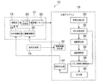
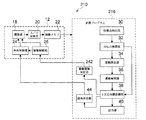
図1に示すように、本実施の形態に係る計測装置10は、車両(図示省略)に搭載され、かつ、画角を切り替えながら計測対象物を撮像して画像を生成する画像撮像装置12と、車両の走行速度を計測する速度計測部14と、画像撮像装置12から得られる画像に基づいて、計測対象物の3次元座標を計測する計測処理ルーチンを実現するための計測プログラムを格納したコンピュータ16とを備えている。
As shown in FIG. 1, a
画像撮像装置12は、計測対象物を撮像し、画像の画像信号を生成する単眼のカメラで構成される撮像部18と、撮像部18で生成された画像信号をA/D変換するA/D変換部20と、A/D変換された画像信号を一時的に格納するための画像メモリ22と、ズーム倍率を変更して画角を制御する画角制御部24と、撮像間隔に基づく撮像タイミングや撮像タイミングに応じた画角制御部24による画角の変更タイミングを制御する撮像制御部26とを備えている。
The image capturing
コンピュータ16に格納されている計測プログラムは、画像撮像装置12により得られた複数の画像の各々から、画像上で追跡しやすい特徴点を複数抽出する特徴点抽出部30と、特徴点抽出部30により得られた2つの画像の各々における特徴点から、2つ画像の間で対応する対応点を検索する対応点検索部32と、対応点検索部32で得られた各対応点における各画像の画像座標を入力として、対応点が検索された一方の画像を撮像したときの画像撮像装置12の位置姿勢を基準とした、対応点が検索された他方の画像を撮像したときの画像撮像装置12の位置姿勢への変化(位置姿勢の相対関係)を、画像撮像装置12の運動のXYZ軸方向の移動量及びXYZ軸を基準とする回転量として算出する運動算出部34と、運動算出部34によって算出された移動量及び回転量に基づいて、線形補間によって、対応点が検索された一方の画像を撮像してから対応点が検索された他方の画像を撮像するまでの間における画像撮像装置12の移動量及び回転量を補間する運動補間部36と、計測対象物の3次元座標を計測する3次元座標計測部38と、3次元座標計測部38の結果を出力する出力部40とを備えている。
The measurement program stored in the
また、計測プログラムは、速度計測部14によって計測された走行速度に基づいて、画像撮像装置12の撮像間隔を決定する撮像間隔決定部42と、3次元座標計測部38によって前回計測された計測対象物の3次元座標に基づいて、画像撮像装置12の画角を決定する画角決定部44とを備えている。
The measurement program also includes an imaging
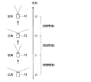
画像撮像装置12は、図2に示すように、画角制御部24によって、画角を広い画角と狭い画角とに切り替えて、広い画角の画像と狭い画角の画像とを交互に撮像する。また、撮像制御部26によって、撮像間隔時間tが制御され、撮像間隔時間tで連続して画像が撮像される。
As shown in FIG. 2, the
コンピュータ16の撮像間隔決定部42は、撮像間隔として、広い画角の画像間での対応点の画像上での動き量の予測値の平均又は最大値が、しきい値以上となる時間を決定する。例えば、図2の時刻t2の広角画像を撮像したときに、撮像間隔を決定することを考える。
The imaging
このとき、速度計測部14により計測した走行速度を利用する。速度計測部14から推定される時刻t0から時刻t2まで(上記図2参照)の2tの間の車両の3次元移動量を(mx,my,mz)とする。また、広角画像撮像時の撮像部18のキャリブレーション行列Kを以下の(1)式で定義する。
At this time, the traveling speed measured by the

ただし、fxは、撮像部18のX方向の焦点距離、fyは、撮像部18のY方向の焦点距離、(cu,cv)は画像中心である。なお、画像上の画像座標は、X方向に対応するU方向の座標uとY方向に対応するV方向の座標vとで表されるものとする。
However, f x is the focal length in the X direction of the
このとき、時刻t0において3次元座標が(x,y,z)と計測された対応点の時刻t2での画像上での予測位置の画像座標を以下の(2)式で表わすと、この画像座標は、以下の(3)式を用いて計算される。 At this time, when the image coordinates of the predicted position on the image at the time t 2 of the corresponding point whose three-dimensional coordinates are measured as (x, y, z) at the time t 0 are expressed by the following equation (2): The image coordinates are calculated using the following equation (3).
この対応点の時刻t0での画像座標を(u,v)としたとき、動き量の予測値は以下の(5)式で表わされる。 When the image coordinates of the corresponding point at time t 0 are (u, v), the motion amount prediction value is expressed by the following equation (5).
従って、上記(5)式で表される動き量の予測値の平均又は最大値が、しきい値以上となるように、3次元移動量(mx,my,mz)を求め、求められた3次元移動量及び速度計測部14により計測された走行速度から、撮像間隔時間tを決定する。これにより、車両の走行速度が遅いほど、撮像間隔が広くなるように撮像間隔時間tが決定される。
Therefore, calculated above (5) average or maximum value of the predicted value of the motion amount of the formula is, so that the above threshold value, the three-dimensional moving amount of (m x, m y, m z), calculated The imaging interval time t is determined from the obtained three-dimensional movement amount and the traveling speed measured by the
また、画角決定部44は、前回の計測タイミングで3次元座標計測部38により得られた対応点の3次元座標の分布に基づいて、3次元座標の車両からの距離が遠いほど、狭くなるように狭い画角を決定する。例えば、上述した方法で撮像間隔時間tを決定したとき、時間2tの間における正面付近に存在する画像上での計測対象物上の対応点の動き量の予測値の平均又は最大値が、しきい値以上となるように、焦点距離を設定し、設定された焦点距離に基づいて、狭い画角を決定する。なお、広い画角については、撮像部18で設定可能な最大の画角に決定すればよい。
In addition, the angle of
特徴点抽出部30は、画像撮像装置12から得られる同じ画角で異なる時刻に撮像した2枚の画像から、それぞれ特徴点を抽出する。特徴点とは、周囲の点と区別でき、異なる画像間で対応関係を求めることが容易な点のことを指す。特徴点は、2次元的に濃淡変化の勾配値が大きくなる画素を検出する方法(例えばHarrisオペレータなど)を用いて、自動的に抽出される。Harrisオペレータを用いる方法では、以下に説明するように、特徴点を抽出する。まず、画像の点(u,v)の輝度をI(u,v)として、以下の(6)式によって、行列Mを計算する。
The feature
ただし、Iu,Ivはそれぞれ水平方向、垂直方向の微分、Gσは標準偏差σのガウス分布による平滑化を表す。 However, I u and I v represent horizontal and vertical differentiation, respectively, and G σ represents smoothing by a Gaussian distribution with a standard deviation σ.
そして、上記(6)式で計算された行列Mの固有値λ1、λ2を用いて、以下の(7)式によりコーナー強度を計算する。 Then, using the eigenvalues λ 1 and λ 2 of the matrix M calculated by the above equation (6), the corner strength is calculated by the following equation (7).
ただし、kは予め設定される定数であって、0.04〜0.06の値が一般に用いられる。Harrisオペレータを用いる方法では、このコーナー強度がしきい値以上でかつ極大となる点を選択し、選択された点を特徴点として抽出する。 However, k is a preset constant, and a value of 0.04 to 0.06 is generally used. In the method using the Harris operator, a point at which the corner intensity is equal to or greater than a threshold value is selected, and the selected point is extracted as a feature point.
対応点検索部32は、特徴点抽出部30において2つの画像の各々から抽出された特徴点について、2つの画像間での対応付けを行って、2つの画像間の対応点を検索する。画像間での特徴点の対応付けでは、特徴点周辺に設定した小領域での輝度分布が似ている点の組を選択し、選択された点の組を対応点とする。2つの特徴点が似ているかどうかの判定にはSSD(Sum of Squared Differences)などの値を用いればよい。
The corresponding
また、対応点検索部32は、特徴点抽出部30において2つの広角画像の各々から抽出された特徴点について、2つの広角画像間の対応点を少なくとも8組検索する。
The corresponding
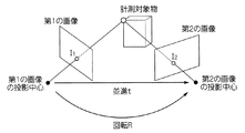
運動算出部34は、対応点検索部32より得られる2つの広角画像における少なくとも8組の対応点の画像座標から、2つの広角画像の各々が撮像されたときの画像撮像装置12の位置及び姿勢の変化(XYZ軸方向の移動量及びXYZ軸を基準とする回転量)を計算する。位置姿勢の変化は、図3に示すように、第1の画像から第2の画像への回転行列R(X軸を基準とする回転量、Y軸を基準とする回転量、Z軸を基準とする回転量)と、並進ベクトルt(X軸方向の移動量tx、Y軸方向の移動量ty、Z軸方向の移動量tz)との6要素から構成される運動である。なお、回転行列R及び並進ベクトルtの要素は、2つの画像間の画像座標の変換を表す物理量である。
The
ここで、第1の画像から第2の画像への回転行列Rと並進ベクトルtとの計算方法について説明する。第1の画像におけるn点の対応点の画像座標Iiと第2の画像におけるn点の対応点の画像座標Ii’とについて(n≧8)、対応点が正しくて誤差がなければ、以下の(8)式を満たす3×3行列Fが存在する。 Here, a calculation method of the rotation matrix R and the translation vector t from the first image to the second image will be described. For the image coordinates I i of the corresponding points of the n points in the first image and the image coordinates I i ′ of the corresponding points of the n points in the second image (n ≧ 8), if the corresponding points are correct and there is no error, There is a 3 × 3 matrix F that satisfies the following equation (8).
ただし、Ii=(ui,vi,1)T、Ii’=(ui’,vi’,1)Tであり、第1の画像での画像座標(ui,vi)の点に対応する第2の画像での点の画像座標が(ui’,vi’)である。 However, I i = (u i , v i , 1) T , I i ′ = (u i ′, v i ′, 1) T , and the image coordinates (u i , v i ) in the first image The image coordinates of the point in the second image corresponding to the point are (u i ′, v i ′).
ここで、上記(8)式を満たす行列Fは、定数倍の不定性を持っている。すなわち、Fsが上記(8)式を満たす場合には、αFsも上記(8)式を満たす(ただし、aは実数)。よって、行列Fを以下の(9)式のように表すことができる。 Here, the matrix F satisfying the equation (8) has a constant multiple indefiniteness. That is, when F s satisfies the above equation (8), αF s also satisfies the above equation (8) (where a is a real number). Therefore, the matrix F can be expressed as the following equation (9).
また、上記(8)式、(9)式より、以下の(10)式が成り立つ。 Further, from the above formulas (8) and (9), the following formula (10) is established.
ここで、8組以上の対応点Ii、Ii’があれば、上記(10)式が少なくとも8つ得られるため、8つの変数f11〜f32を求めることができる。なお、得られる8つの式が互いに独立である必要があり、また、誤差が含まれる場合であっても安定して計算するために、他の対応点の組となるべく異なる動きをしている特徴点の組を対応点として検索することが好ましい。 Here, if there are eight or more pairs of corresponding points I i and I i ′, at least eight of the above formula (10) are obtained, so that eight variables f 11 to f 32 can be obtained. It should be noted that the eight formulas obtained need to be independent from each other, and even when errors are included, in order to perform stable calculation, other corresponding points are moving as differently as possible. It is preferable to search a set of points as corresponding points.
上述したように行列Fが計算でき、また、撮像部18のキャリブレーション行列Kが既知である場合には、以下の(11)式、(12)式より、回転行列Rと並進ベクトルtとを計算することができる.
When the matrix F can be calculated as described above and the calibration matrix K of the
運動補間部36は、運動算出部34により位置姿勢の変化が算出された2枚の画像の撮像時刻の間に撮像された画像について、画像撮像装置12の位置姿勢の変化(回転行列及び並進ベクトル)を、運動算出部34により得られた位置姿勢の変化を線形補間することによって求める。例えば、図2において時刻t0とt2の広角画像について算出された回転行列が表わす回転量及び並進ベクトルの各々を線形補間して、時刻t0の広角画像を基準とした時刻t1の狭角画像の回転行列が表わす回転量及び並進ベクトルの各々を算出する。また、時刻t2とt4の広角画像について算出された回転行列及び並進ベクトルの各々を線形補間して、時刻t2の広角画像を基準とした時刻t3の狭角画像の回転行列及び並進ベクトルの各々を算出する。そして、時刻t1、t3の狭角画像の回転行列及び並進ベクトルに基づいて、時刻t1とt3の狭角画像間の回転行列及び並進ベクトルの各々を算出する。
The
3次元座標計測部38は、対応点検索部32から得られる2つの狭角画像間での対応点の画像座標、及び運動補間部36から得られる2つの狭角画像間の回転行列及び並進ベクトルを用いて、計測対象物上の対応点の3次元座標を計算する。対応点の3次元座標は以下の方法により計算できる。
The three-dimensional coordinate
まず、2枚の狭角画像の各々の対応点の画像座標を(u,v)、(u’,v’)とし、狭角画像間の回転行列をRとし、並進ベクトルをtとし、撮像部18のキャリブレーション行列をKとしたとき、以下の(13)式、(14)式のような行列P、P’を定義する。
First, the image coordinates of the corresponding points of each of the two narrow-angle images are (u, v), (u ′, v ′), the rotation matrix between the narrow-angle images is R, the translation vector is t, and imaging is performed. When the calibration matrix of the
そして、pi,p’iをそれぞれ行列P,P’の第i行のベクトルとすると、対応点の3次元座標X=(x,y,z,1)Tは以下の(15)式の解として求めることができる。 If p i and p ′ i are the vectors of the i-th row of the matrices P and P ′, respectively, the three-dimensional coordinates X = (x, y, z, 1) T of the corresponding points are expressed by the following equation (15). It can be obtained as a solution.
次に、本実施の形態に係る計測装置10の作用について説明する。なお、計測装置10を搭載した車両の走行中に、計測対象物の3次元座標を計測する場合を例に説明する。
Next, the operation of the
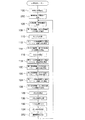
まず、画像撮像装置12が、計測対象物に向けられ、画像撮像装置12によって計測対象物の連続撮像が開始されると、コンピュータ16において、図4に示す計測対象物の3次元座標を計測するための計測処理ルーチンが実行される。
First, when the
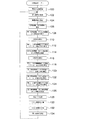
まず、ステップ100において、初期設定として、広い画角と狭い画角とを、撮像部18の予め定められた最大画角に設定し、ステップ102で、速度計測部14で計測された車両の走行速度を取得する。そして、ステップ104において、上記ステップ102で取得された走行速度に基づいて、撮像間隔時間tを決定し、決定された撮像間隔時間tで連続撮像するように、画像撮像装置12の撮像間隔を制御する。これにより、画像撮像装置12は、画角を設定された広い画角と狭い画角とに切り替えながら、設定された撮像間隔時間tで、広い画角の画像と狭い画角の画像とを交互に撮像する。
First, in
次のステップ106では、画像撮像装置12から、広い画角の第1広角画像(例えば撮像時刻t0)、狭い画角の第1狭角画像(撮像時刻t1=t0+t)、広い画角の第2広角画像(撮像時刻t2=t0+2t)、狭い画角の第2狭角画像(撮像時刻t3=t0+3t)、及び広い画角の第3広角画像(撮像時刻t4=t0+4t)を順に取得する。
In the
そして、ステップ108において、第1広角画像と第2広角画像との各々から特徴点を複数抽出し、ステップ110で、上記ステップ108で抽出された複数の特徴点から、第1広角画像と第2広角画像との間で対応する対応点を少なくとも8組検索する。そして、ステップ112において、上記ステップ110で検索された少なくとも8組の対応点の画像座標に基づいて、第1広角画像を撮像したときの画像撮像装置12の位置姿勢を基準とした第2広角画像を撮像したときの画像撮像装置12の位置姿勢の変化を表わす並進ベクトル及び回転行列を算出する。
In
そして、次のステップ114において、第2広角画像と第3広角画像との各々から特徴点を複数抽出し、ステップ116で、上記ステップ114で抽出された特徴点から、第2広角画像と第3広角画像との間で対応する対応点を少なくとも8組検索する。そして、ステップ118において、上記ステップ116で検索された少なくとも8組の対応点の画像座標に基づいて、第2広角画像を撮像したときの画像撮像装置12の位置姿勢を基準とした第3広角画像を撮像したときの画像撮像装置12の位置姿勢の変化を表わす並進ベクトル及び回転行列を算出する。
In the
そして、ステップ120において、上記ステップ112で算出された並進ベクトル及び回転行列を補間して、第1広角画像を撮像したときの画像撮像装置12の位置姿勢を基準とした第1狭角画像を撮像したときの画像撮像装置12の位置姿勢の変化を表わす並進ベクトル及び回転行列を算出し、次のステップ122において、上記ステップ118で算出された並進ベクトル及び回転行列を補間して、第2広角画像を撮像したときの画像撮像装置12の位置姿勢を基準とした第2狭角画像を撮像したときの画像撮像装置12の位置姿勢の変化を表わす並進ベクトル及び回転行列を算出する。
In
そして、ステップ124において、上記ステップ120、122で算出された並進ベクトル及び回転行列に基づいて、第1狭角画像を撮像したときの画像撮像装置12の位置姿勢を基準とした第2狭角画像を撮像したときの画像撮像装置12の位置姿勢の変化を表わす並進ベクトル及び回転行列を算出する。
In
そして、ステップ126において、第1狭角画像と第2狭角画像との各々から特徴点を複数抽出し、ステップ128で、上記ステップ126で抽出された特徴点から、第1狭角画像と第2狭角画像との間で対応する対応点を少なくとも1組検索する。
In
次のステップ130では、上記ステップ124で算出された第1狭角画像と第2狭角画像との間における並進ベクトル及び回転行列、及び上記ステップ128で検索された第1狭角画像と第2狭角画像とにおける対応点の画像座標に基づいて、この対応点が示す計測対象物上の特徴点の3次元座標を計算し、ステップ132において、計算された計測対象物の特徴点の3次元座標を、コンピュータ16のディスプレイ(図示省略)に表示する。
In the
そして、ステップ134において、上記ステップ134で計算された3次元座標に基づいて、狭い画角を決定し、画像撮像装置12の狭い画角が、決定された狭い画角となるように制御して、ステップ102へ戻って、設定された広い画角の画像と新たに決定された狭い画角の画像とに基づいて、次の計測タイミングにおける計測対象物上の特徴点の3次元座標を計測する。
In
以上説明したように、第1の実施の形態に係る計測装置によれば、狭い画角で撮像された2つの画像に基づいて、計測対象物上の特徴点から対応点を検索し、広い画角で撮像された複数の画像から、2つの狭角画像の各々を撮像したときの画像撮像装置の位置姿勢の変化を表わす並進ベクトル及び回転行列を推定することにより、画像撮像装置の運動推定の精度と計測対象物上の対応点の検出精度とを向上させることができるため、計測対象物の3次元座標を高精度に計測することができる。 As described above, according to the measurement apparatus according to the first embodiment, the corresponding points are searched from the feature points on the measurement object based on the two images captured at a narrow angle of view, and a wide image is obtained. By estimating a translation vector and a rotation matrix representing a change in position and orientation of the image pickup device when each of the two narrow-angle images is picked up from a plurality of images picked up at angles, motion estimation of the image pickup device can be performed. Since the accuracy and the detection accuracy of corresponding points on the measurement object can be improved, the three-dimensional coordinates of the measurement object can be measured with high accuracy.
また、画角を広角と狭角とに切り替えて撮像し、広角画像から幅広い範囲で検索された複数の対応点に基づいて高精度に運動推定した結果と、狭角画像で高精度に特徴点の動きを検出した結果とから、計測対象物の3次元座標を高精度に計測することができる。 In addition, the angle of view is switched between wide angle and narrow angle, and the results of high-precision motion estimation based on multiple corresponding points searched from a wide range of wide-angle images and high-precision feature points in narrow-angle images It is possible to measure the three-dimensional coordinates of the measurement object with high accuracy from the result of detecting the movement of.
また、撮像部の画角を広角と狭角とに切り替えることにより、一つの撮像部によって、広い画角で撮像された画像と狭い画角で撮像された画像とを得ることができる。 Further, by switching the angle of view of the imaging unit between a wide angle and a narrow angle, an image captured with a wide angle of view and an image captured with a narrow angle of view can be obtained by one imaging unit.
また、2つの広角画像間で対応した少なくとも8組の対応点に基づいて、並進ベクトル及び回転行列の各々を精度よく算出することができる。 Moreover, each of the translation vector and the rotation matrix can be calculated with high accuracy based on at least eight sets of corresponding points corresponding to each other between the two wide-angle images.
狭い画角の画像を撮像した前後で撮像された2枚の広い画角の画像から算出された並進ベクトル及び回転行列に基づいて、狭い画角の画像を撮像したときの画像撮像装置の並進ベクトル及び回転行列を精度よく推定することができる。 A translation vector of an image capturing apparatus when a narrow-angle image is captured based on a translation vector and a rotation matrix calculated from two wide-angle images captured before and after capturing a narrow-angle image. And the rotation matrix can be estimated with high accuracy.
また、前回計測された計測対象物の3次元座標の車両からの距離が遠いほど、小さくなるように狭い画角を決定することにより、狭い画角で撮像された画像間で検索される計測対象物上の対応点の検出精度を向上させることができる。 In addition, a measurement object that is searched between images captured at a narrow angle of view by determining a narrow angle of view so that the distance from the vehicle of the three-dimensional coordinates of the measurement object measured last time increases. The detection accuracy of the corresponding points on the object can be improved.
また、車両の走行速度が遅くなるほど、運動推定および動き検出に用いる画像間の撮像間隔が広くなるように決定することで、画像間で検索される対応点の動きが大きくなるため、撮像手段の運動推定の精度及び動き検出の制度を向上させることができる。 In addition, as the vehicle traveling speed decreases, the movement of corresponding points searched between images increases by determining that the imaging interval between images used for motion estimation and motion detection becomes wider. The accuracy of motion estimation and the motion detection system can be improved.
また、単眼カメラで撮像した連続画像を用いて計測対象物の3次元座標を高精度に計測することができる。 In addition, it is possible to measure the three-dimensional coordinates of the measurement object with high accuracy using continuous images captured by a monocular camera.
なお、上記の実施の形態では、2つの画像から抽出された複数の特徴点から、2つの画像の間で対応する点を検索する場合を例に説明したが、2つの画像の一方の画像から特徴点を抽出し、他方の画像から、抽出された特徴点に対応する対応点を検索するようにしてもよい。 In the above embodiment, the case where a corresponding point is searched between two images from a plurality of feature points extracted from the two images has been described as an example, but from one of the two images. A feature point may be extracted, and a corresponding point corresponding to the extracted feature point may be searched from the other image.
また、狭角画像から検索された対応点についてのみ3次元座標を計測する場合を例に説明したが、狭角画像に写っていない範囲の対応点であって、かつ、広角画像に写っている対応点についても、3次元座標を計測するようにしてもよい。この場合には、並進ベクトル及び回転行列を算出するために対応点を検索した第1広角画像及び第2広角画像の特徴点から、第1広角画像と第2広角画像との間で対応する対応点を検索し、検索された第1広角画像と第2広角画像とにおける対応点の画像座標、及び第1広角画像と第2広角画像との間における並進ベクトル及び回転行列に基づいて、対応点が示す計測対象物上の特徴点の3次元座標を計算すればよい。これによって、狭角画像を用いることで中心部(正面付近)にある計測対象物の距離精度を高くしながら、広角画像のみに写る特徴点の3次元座標についても計算し、広角な視野で計測対象物の3次元座標を得ることができる。 Moreover, although the case where the three-dimensional coordinates are measured only for the corresponding points retrieved from the narrow-angle image has been described as an example, the corresponding points are in the range that is not reflected in the narrow-angle image and are reflected in the wide-angle image. You may make it measure a three-dimensional coordinate also about a corresponding point. In this case, the corresponding correspondence between the first wide-angle image and the second wide-angle image from the feature points of the first wide-angle image and the second wide-angle image obtained by searching the corresponding points to calculate the translation vector and the rotation matrix. The corresponding point is searched based on the image coordinates of the corresponding point in the searched first wide angle image and the second wide angle image, and the translation vector and rotation matrix between the first wide angle image and the second wide angle image. What is necessary is just to calculate the three-dimensional coordinate of the feature point on the measurement target indicated by. By using a narrow-angle image, the distance accuracy of the measurement object in the center (near the front) is increased, and the three-dimensional coordinates of the feature points that appear only in the wide-angle image are calculated and measured with a wide-angle field of view. The three-dimensional coordinates of the object can be obtained.
また、交互に狭い画角と広い画角とを切り替えて撮像する場合を例に説明したが、これに限定されることなく、狭い画角の画像又は広い画角の画像が連続して撮像されるように、画角を切り替えてもよい。この場合には、前後に撮像された広角画像、前に撮像された2つの広角画像、又は後に撮像された2つの広角画像における移動ベクトル及び回転行列を線形補間して、狭角画像を撮像したときの画像撮像装置の並進ベクトル及び回転行列を求めるようにすればよい。 In addition, although an example in which imaging is performed by alternately switching between a narrow field angle and a wide field angle has been described, the present invention is not limited to this, and an image with a narrow field angle or an image with a wide field angle is continuously captured. As shown, the angle of view may be switched. In this case, a wide-angle image captured before and after, two wide-angle images captured before, or a linear interpolation of the movement vector and rotation matrix in the two wide-angle images captured later to capture a narrow-angle image What is necessary is just to obtain | require the translation vector and rotation matrix of an image pick-up device at the time.
また、2つの狭角画像の各々について、並進ベクトル及び回転行列を求める際に、共通となる第2広角画像を用いて算出された並進ベクトル及び回転行列の各々を補間した場合を例に説明したが、これに限定されるものではなく、例えば、第1広角画像及び第2広角画像を用いて算出された並進ベクトル及び回転行列の各々を補間して、第1狭角画像における並進ベクトル及び回転行列を算出し、また、第3広角画像及び第4広角画像を用いて算出された並進ベクトル及び回転行列の各々を補間して、第2狭角画像における並進ベクトル及び回転行列を算出するようにしてもよい。この場合に、基準となる広角画像を一つ定めておき(例えば第1広角画像を基準とする)、この基準となる広角画像と第1狭角画像との間の並進ベクトル及び回転行列、基準となる広角画像と第2狭角画像との間の並進ベクトル及び回転行列と、第1、2狭角画像の各々における並進ベクトル及び回転行列とに基づいて、第1、2狭角画像間の並進ベクトル及び回転行列を算出するようにすればよい。また、2つの広角画像間の並進ベクトル及び回転行列を線形補間して、第1狭角画像における並進ベクトル及び回転行列と、第2狭角画像における並進ベクトル及び回転行列とを算出するようにしてもよい。 Further, in the case of obtaining the translation vector and the rotation matrix for each of the two narrow-angle images, the case where each of the translation vector and the rotation matrix calculated using the common second wide-angle image is interpolated has been described as an example. However, the present invention is not limited to this. For example, the translation vector and the rotation in the first narrow-angle image are interpolated by translating each of the translation vector and the rotation matrix calculated using the first wide-angle image and the second wide-angle image. A matrix is calculated, and each of the translation vector and the rotation matrix calculated using the third wide-angle image and the fourth wide-angle image is interpolated to calculate the translation vector and the rotation matrix in the second narrow-angle image. May be. In this case, one reference wide-angle image is determined (for example, the first wide-angle image is used as a reference), the translation vector and rotation matrix between the reference wide-angle image and the first narrow-angle image, the reference Between the first and second narrow-angle images based on the translation vector and rotation matrix between the wide-angle image and the second narrow-angle image and the translation vector and rotation matrix in each of the first and second narrow-angle images. A translation vector and a rotation matrix may be calculated. The translation vector and rotation matrix between the two wide-angle images are linearly interpolated to calculate the translation vector and rotation matrix in the first narrow-angle image and the translation vector and rotation matrix in the second narrow-angle image. Also good.
また、画像撮像装置に単眼のカメラを用いた場合を例に説明したが、広い画角の画像を撮像するカメラと狭い画角の画像を撮像するカメラとを備えた複眼カメラを用いるようにしてもよい。この場合には、複眼カメラが独立して動かないようして、同じように位置姿勢が変化するようにすればよい。 In addition, the case where a monocular camera is used as the image capturing apparatus has been described as an example. Also good. In this case, the position and orientation may be changed in the same manner so that the compound-eye camera does not move independently.
また、計測対象物上の対応点の3次元座標を計測して出力する場合を例に説明したが、計測された3次元座標に基づいて、車両からの対応点までの距離を計測し、計測された距離を出力するようにしてもよい。 Moreover, although the case where the three-dimensional coordinate of the corresponding point on the measurement object is measured and output has been described as an example, the distance from the vehicle to the corresponding point is measured based on the measured three-dimensional coordinate, and the measurement is performed. The distance may be output.
また、2つの狭角画像から、対応点を検索する場合を例に説明したが、これに限定されるものではなく、3つ以上の狭角画像から、対応点を検索するようにしてもよい。3枚の狭角画像から対応点を検索する場合には、第1狭角画像と第2狭角画像との間で対応する対応点を検索すると共に、第2狭角画像と第3狭角画像との間で対応する対応点を検索して、第1狭角画像、第2狭角画像、及び第3狭角画像の間で対応する点を検索する。そして、対応点の第1狭角画像及び第2狭角画像の各々の座標から、3次元座標を計算し、第1狭角画像及び第3狭角画像の各々の座標から、3次元座標を計算する。計算された2つの3次元座標のズレが小さい場合には、最も距離が離れた第1狭角画像及び第3狭角画像から計算された3次元座標を、正しい計測値として採用し、一方、計算された2つの3次元座標のズレが大きい場合には、対応点の対応に誤りがあるとして、計算された2つの3次元座標を棄却する。 Further, the case where the corresponding points are searched from the two narrow-angle images has been described as an example, but the present invention is not limited to this, and the corresponding points may be searched from three or more narrow-angle images. . When searching for corresponding points from three narrow-angle images, corresponding points between the first narrow-angle image and the second narrow-angle image are searched, and the second narrow-angle image and the third narrow-angle image are searched. Corresponding points corresponding to the image are searched, and corresponding points are searched among the first narrow-angle image, the second narrow-angle image, and the third narrow-angle image. Then, the three-dimensional coordinates are calculated from the coordinates of the corresponding first and second narrow-angle images, and the three-dimensional coordinates are calculated from the coordinates of the first and third narrow-angle images. calculate. When the difference between the two calculated three-dimensional coordinates is small, the three-dimensional coordinates calculated from the first and third narrow-angle images that are most distant from each other are adopted as correct measurement values, If the difference between the two calculated three-dimensional coordinates is large, it is determined that there is an error in the correspondence between the corresponding points, and the two calculated three-dimensional coordinates are rejected.
また、上記の実施の形態では、画像撮像装置の位置姿勢の変化を表わすものとして、並進ベクトル及び回転行列を算出する場合を例に説明したが、これに限定されるものではなく、画像撮像装置の位置姿勢の変化を表わすものとして他の指標を算出するようにしてもよい。 In the above-described embodiment, the case where the translation vector and the rotation matrix are calculated as an example representing the change in the position and orientation of the image capturing apparatus has been described. However, the present invention is not limited to this. Other indices may be calculated as representing changes in the position and orientation of
次に、第2の実施の形態について説明する。なお、第1の実施の形態と同様の構成となっている部分については、同一符号を付して説明を省略する。 Next, a second embodiment will be described. In addition, about the part which becomes the structure similar to 1st Embodiment, the same code | symbol is attached | subjected and description is abbreviate | omitted.
第2の実施の形態では、前回計測された計測対象物上の対応点の3次元座標に基づいて、撮像間隔を決定している点が第1の実施の形態と異なっている。 The second embodiment is different from the first embodiment in that the imaging interval is determined based on the three-dimensional coordinates of the corresponding points on the measurement object measured last time.
図5に示すように、第2の実施の形態に係る計測装置210は、画像撮像装置12と、コンピュータ216とを備えており、コンピュータ216に格納されている計測プログラムは、特徴点抽出部30と、対応点検索部32と、運動算出部34と、運動補間部36と、3次元座標計測部38と、出力部40と、3次元座標計測部38によって前回計測された計測対象物の3次元座標に基づいて、画像撮像装置12の撮像間隔を決定する撮像間隔決定部242と、画角決定部44とを備えている。
As shown in FIG. 5, the
撮像間隔決定部242は、前回計測された計測対象物の3次元座標に基づいて、撮像間隔として、広い画角の画像間での対応点の画像上での動き量の予測値の平均又は最大値が、しきい値以上となる時間を決定する。例えば、前回計測された計測対象物の3次元座標から得られる車両からの距離が遠いほど、動き量の予測値が小さくなるため、撮像間隔が広くなるように撮像間隔時間を長く決定し、広い画角の画像間での対応点の画像上での動き量の予測値の平均又は最大値が、しきい値以上となるようにする。
Based on the three-dimensional coordinates of the measurement object measured last time, the imaging
次に第2の実施の形態に係る計測処理ルーチンについて図6を用いて説明する。なお、第1の実施の形態と同様の処理については、同一符号を付して詳細な説明を省略する。 Next, a measurement processing routine according to the second embodiment will be described with reference to FIG. In addition, about the process similar to 1st Embodiment, the same code | symbol is attached | subjected and detailed description is abbreviate | omitted.
まず、ステップ100において、初期設定として、広い画角と狭い画角とを、撮像部18の予め定められた最大画角に設定し、ステップ250で、撮像間隔時間tとして初期値を設定し、初期値の撮像間隔時間tで連続撮像するように、画像撮像装置12の撮像間隔を制御する。
First, in
次のステップ106では、画像撮像装置12から、第1広角画像、第1狭角画像、第2広角画像、第2狭角画像、及び第3広角画像を順に取得する。そして、ステップ108において、第1広角画像と第2広角画像との各々から特徴点を複数抽出し、ステップ110で、第1広角画像と第2広角画像との間で対応する対応点を少なくとも8組検索し、そして、ステップ112において、第1広角画像を撮像したときの画像撮像装置12の位置姿勢を基準とした第2広角画像を撮像したときの画像撮像装置12の位置姿勢の変化を表わす並進ベクトル及び回転行列を算出する。
In the
そして、ステップ114において、第2広角画像と第3広角画像との各々から特徴点を複数抽出し、ステップ116で、第2広角画像と第3広角画像との間で対応する対応点を少なくとも8組検索し、そして、ステップ118において、第2広角画像を撮像したときの画像撮像装置12の位置姿勢を基準とした第3広角画像を撮像したときの画像撮像装置12の位置姿勢の変化を表わす並進ベクトル及び回転行列を算出する。
In
そして、ステップ120において、第1狭角画像を撮像したときの画像撮像装置12の位置姿勢の変化を表わす並進ベクトル及び回転行列を算出し、次のステップ122において、第2狭角画像を撮像したときの画像撮像装置12の位置姿勢の変化を表わす並進ベクトル及び回転行列を算出する。そして、ステップ124において、第1狭角画像を撮像したときの画像撮像装置12の位置姿勢を基準とした第2狭角画像を撮像したときの画像撮像装置12の位置姿勢の変化を表わす並進ベクトル及び回転行列を算出する。
In
次のステップ126では、第1狭角画像と第2狭角画像との各々から特徴点を複数抽出し、ステップ128で、第1狭角画像と第2狭角画像との間で対応する対応点を少なくとも1組検索し、次のステップ130において、対応点が示す計測対象物上の特徴点の3次元座標を計算し、ステップ132において、計算された計測対象物の特徴点の3次元座標を、コンピュータ16のディスプレイに表示する。
In the
そして、ステップ134において、上記ステップ134で計算された3次元座標に基づいて、狭い画角を決定し、画像撮像装置12の狭い画角が、決定された狭い画角となるように制御する。次のステップ252では、上記ステップ134で計算された3次元座標に基づいて、撮像間隔時間を決定し、画像撮像装置12の撮像間隔が、決定された撮像間隔時間となるように制御する。これにより、設定された広い画角と新たに決定された狭い画角とに切り替えながら、新たに決定された撮像間隔時間tで、広い画角の画像と狭い画角の画像とを交互に撮像する。そして、ステップ106へ戻り、設定された広い画角の画像と新たに決定された狭い画角の画像とに基づいて、次の計測タイミングにおける計測対象物上の特徴点の3次元座標を計測する。
In
このように、前回計測された3次元座標の車両からの距離が遠いほど、広くなるように撮像間隔を決定することにより、画像間で検索される対応点の動きが大きくなるため、画像撮像装置の運動推定の精度を向上させることができる。 In this way, since the movement of the corresponding point searched between images increases by determining the imaging interval so that the distance from the vehicle of the three-dimensional coordinates measured last time increases, the image imaging device The accuracy of motion estimation can be improved.
10、210 計測装置
12 画像撮像装置
14 速度計測部
16、216 コンピュータ
18 撮像部
24 画角制御部
26 撮像制御部
30 特徴点抽出部
32 対応点検索部
34 運動算出部
36 運動補間部
38 3次元座標計測部
42、242 撮像間隔決定部
44 画角決定部
DESCRIPTION OF SYMBOLS 10,210
Claims (12)
前記撮像手段によって前記第2画角で撮像された少なくとも2つの画像の各々から、前記計測対象物上の特徴点であって、かつ、前記少なくとも2つの画像間で対応した点を検索する検索手段と、
前記撮像手段によって前記第1画角で撮像した複数の画像に基づいて、前記複数の画像の各々を撮像したときの前記撮像手段の位置及び姿勢の相対関係を算出する位置姿勢算出手段と、
前記位置姿勢算出手段によって算出された前記位置及び姿勢の相対関係に基づいて、前記第2画角で撮像された前記少なくとも2つの画像の各々を撮像したときの前記撮像手段の位置及び姿勢の相対関係を推定する位置姿勢推定手段と、
前記検索手段によって検索された点と前記位置姿勢推定手段によって推定された前記位置及び姿勢の相対関係とに基づいて、前記検索された点の3次元位置を計測する位置計測手段と、
を含む計測装置。 Imaging means mounted on a moving body that outputs a plurality of images obtained by imaging a measurement object at a first angle of view and a plurality of images obtained by imaging the measurement object at a second angle of view smaller than the first angle of view; ,
Retrieval means for retrieving feature points on the measurement object and corresponding points between the at least two images from each of at least two images captured at the second angle of view by the imaging means. When,
Position and orientation calculation means for calculating a relative relationship between the position and orientation of the imaging means when each of the plurality of images is taken based on the plurality of images taken at the first angle of view by the imaging means;
Based on the relative relationship between the position and orientation calculated by the position and orientation calculation means, the relative position and orientation of the imaging means when each of the at least two images captured at the second angle of view is captured. Position and orientation estimation means for estimating the relationship;
Position measuring means for measuring the three-dimensional position of the searched point based on the point searched by the searching means and the relative relationship between the position and posture estimated by the position and posture estimating means;
Measuring device including
前記位置姿勢算出手段は、前記第1画像を撮像する前に前記撮像手段によって前記第1画角で第3画像を撮像したときの前記撮像手段の位置及び姿勢と、前記第1画像の撮像と前記第2画像の撮像との間に前記撮像手段によって前記第1画角で第4画像を撮像したときの前記撮像手段の位置及び姿勢との相対関係を表わす3軸方向の第1移動量及び3軸を基準とする第1回転量を算出すると共に、前記第4画像を撮像したときの前記撮像手段の位置及び姿勢と、前記第2画像を撮像した後に前記撮像手段によって前記第1画角で第5画像を撮像したときの前記撮像手段の位置及び姿勢との相対関係を表わす3軸方向の第2移動量及び3軸を基準とする第2回転量を算出し、
前記位置姿勢推定手段は、前記位置姿勢算出手段によって算出された前記第1移動量、前記第2移動量、前記第1回転量、及び前記第2回転量に基づいて、前記第1画像を撮像したときの前記撮像手段の位置及び姿勢と、前記第2画像を撮像したときの前記撮像手段の位置及び姿勢との相対関係を表わす前記移動量及び前記回転量を推定する請求項1〜請求項6の何れか1項記載の計測装置。 The search means includes a first image picked up at the second angle of view by the image pickup means and a second image picked up at the second angle of view by the image pickup means after picking up the first image. A feature point on the measurement object, the corresponding point is searched between the first image and the second image;
The position / orientation calculation means includes the position and orientation of the image pickup means when the third image is picked up at the first angle of view by the image pickup means before the first image is picked up, and the image pickup of the first image. A first movement amount in a triaxial direction representing a relative relationship with the position and orientation of the imaging means when the fourth image is taken by the imaging means at the first angle of view between the second image and the second image; The first rotation amount with respect to three axes is calculated, the position and orientation of the imaging unit when the fourth image is captured, and the first angle of view by the imaging unit after the second image is captured. Calculating a second movement amount in the three-axis direction representing a relative relationship with the position and orientation of the imaging means when the fifth image is picked up and a second rotation amount based on the three axes,
The position / orientation estimation unit picks up the first image based on the first movement amount, the second movement amount, the first rotation amount, and the second rotation amount calculated by the position / orientation calculation unit. The amount of movement and the amount of rotation representing a relative relationship between the position and orientation of the imaging unit when the second image is captured and the position and orientation of the imaging unit when the second image is captured are estimated. 6. The measuring device according to any one of items 6.
前回計測された前記3次元位置の前記移動体からの距離が遠いほど、小さくなるように前記第2画角を決定する画角決定手段を更に含む請求項1〜請求項8の何れか1項記載の計測装置。 The position measuring means continuously measures the three-dimensional position;
The angle of view determination means for determining the second angle of view so as to decrease as the distance from the moving body of the three-dimensional position measured last time increases. The measuring device described.
前記速度計測手段によって計測された移動速度が遅いほど、前記撮像手段による撮像間隔が広くなるように前記撮像手段を制御する撮像制御手段と、
を更に含む請求項1〜請求項9の何れか1項記載の計測装置。 Speed measuring means for measuring the moving speed of the moving body;
An imaging control means for controlling the imaging means so that an imaging interval by the imaging means becomes wider as the moving speed measured by the speed measuring means is slower;
10. The measuring device according to any one of claims 1 to 9, further comprising:
前回計測された前記3次元位置の前記移動体からの距離が遠いほど、前記撮像手段による撮像間隔が広くなるように前記撮像手段を制御する撮像制御手段を更に含む請求項1〜請求項9の何れか1項記載の計測装置。 The position measuring means continuously measures the three-dimensional position;
10. The imaging control unit according to claim 1, further comprising an imaging control unit that controls the imaging unit such that an imaging interval by the imaging unit becomes wider as a distance from the moving body of the three-dimensional position measured last time is longer. Any one of the measuring devices of a statement.
第1画角で計測対象物を撮像した複数の画像、及び前記第1画角より小さい第2画角で前記計測対象物を撮像した複数の画像を出力する移動体に搭載された撮像手段によって前記第2画角で撮像された少なくとも2つの画像の各々から、前記計測対象物上の特徴点であって、かつ、前記少なくとも2つの画像間で対応した点を検索する検索手段、
前記撮像手段によって前記第1画角で撮像した複数の画像に基づいて、前記複数の画像の各々を撮像したときの前記撮像手段の位置及び姿勢の相対関係を算出する位置姿勢算出手段、
前記位置姿勢算出手段によって算出された前記位置及び姿勢の相対関係に基づいて、前記第2画角で撮像された前記少なくとも2つの画像の各々を撮像したときの前記撮像手段の位置及び姿勢の相対関係を推定する位置姿勢推定手段、及び
前記検索手段によって検索された点と前記位置姿勢推定手段によって推定された前記位置及び姿勢の相対関係とに基づいて、前記検索された点の3次元位置を計測する位置計測手段
として機能させるためのプログラム。 Computer
By an imaging unit mounted on a moving body that outputs a plurality of images obtained by imaging a measurement object at a first angle of view and a plurality of images obtained by imaging the measurement object at a second angle of view smaller than the first angle of view. Search means for searching for a feature point on the measurement object and corresponding points between the at least two images from each of at least two images captured at the second angle of view;
Position and orientation calculation means for calculating a relative relationship between the position and orientation of the imaging means when each of the plurality of images is taken based on the plurality of images taken at the first angle of view by the imaging means;
Based on the relative relationship between the position and orientation calculated by the position and orientation calculation means, the relative position and orientation of the imaging means when each of the at least two images captured at the second angle of view is captured. A position / orientation estimation unit for estimating a relationship; and a three-dimensional position of the retrieved point based on a point retrieved by the retrieval unit and a relative relationship between the position and orientation estimated by the position / orientation estimation unit. A program to function as a position measurement means to measure.
Priority Applications (5)
| Application Number | Priority Date | Filing Date | Title |
|---|---|---|---|
| JP2007147137A JP4809291B2 (en) | 2007-06-01 | 2007-06-01 | Measuring device and program |
| DE112008001487T DE112008001487T5 (en) | 2007-06-01 | 2008-05-15 | Measuring device, measuring method, program and computer-readable carrier |
| US12/602,572 US8295643B2 (en) | 2007-06-01 | 2008-05-15 | Device and associated methodology for measuring three-dimensional positions based on retrieved points from one view angle and positions and postures from another view angle |
| PCT/IB2008/001231 WO2008146114A2 (en) | 2007-06-01 | 2008-05-15 | Measurement device, measurement method, program, and computer readable medium |
| CN200880018492XA CN101681519B (en) | 2007-06-01 | 2008-05-15 | Measurement device and measurement method |
Applications Claiming Priority (1)
| Application Number | Priority Date | Filing Date | Title |
|---|---|---|---|
| JP2007147137A JP4809291B2 (en) | 2007-06-01 | 2007-06-01 | Measuring device and program |
Publications (2)
| Publication Number | Publication Date |
|---|---|
| JP2008298685A JP2008298685A (en) | 2008-12-11 |
| JP4809291B2 true JP4809291B2 (en) | 2011-11-09 |
Family
ID=40020193
Family Applications (1)
| Application Number | Title | Priority Date | Filing Date |
|---|---|---|---|
| JP2007147137A Expired - Fee Related JP4809291B2 (en) | 2007-06-01 | 2007-06-01 | Measuring device and program |
Country Status (5)
| Country | Link |
|---|---|
| US (1) | US8295643B2 (en) |
| JP (1) | JP4809291B2 (en) |
| CN (1) | CN101681519B (en) |
| DE (1) | DE112008001487T5 (en) |
| WO (1) | WO2008146114A2 (en) |
Families Citing this family (19)
| Publication number | Priority date | Publication date | Assignee | Title |
|---|---|---|---|---|
| IL172995A (en) * | 2006-01-05 | 2011-07-31 | Gadi Royz | Method and apparatus for making a virtual movie for use in exploring a site |
| JP5617166B2 (en) * | 2009-02-09 | 2014-11-05 | 日本電気株式会社 | Rotation estimation apparatus, rotation estimation method and program |
| JP2011090400A (en) * | 2009-10-20 | 2011-05-06 | Sony Corp | Image display device, method, and program |
| CN102243764B (en) * | 2010-05-13 | 2015-07-15 | 东软集团股份有限公司 | Motion characteristic point detection method and device |
| US20120054575A1 (en) * | 2010-08-27 | 2012-03-01 | Jeyhan Karaoguz | Method and system for error protection of 3d video |
| WO2013168246A1 (en) * | 2012-05-09 | 2013-11-14 | トヨタ自動車株式会社 | Driving assist device |
| US9667872B2 (en) * | 2012-12-05 | 2017-05-30 | Hewlett-Packard Development Company, L.P. | Camera to capture multiple images at multiple focus positions |
| JP6217227B2 (en) * | 2013-08-12 | 2017-10-25 | 株式会社リコー | Calibration apparatus, method and program |
| KR101844278B1 (en) * | 2014-01-23 | 2018-04-02 | 삼성전자주식회사 | Parameter learning method for estimating posture of articulated object and posture estimating method of articulated object |
| CN105934774A (en) * | 2014-03-24 | 2016-09-07 | 株式会社日立制作所 | Object detection apparatus, object detection method, and mobile robot |
| US9269143B2 (en) * | 2014-07-10 | 2016-02-23 | Trimble Navigation Limited | Camera on a rover surveying system |
| CN110622499B (en) * | 2017-05-16 | 2021-02-05 | 富士胶片株式会社 | Image generation device, image generation system, image generation method, and recording medium |
| KR102045436B1 (en) * | 2017-09-15 | 2019-11-15 | 고려대학교 산학협력단 | Method and apparatus for recognizing curling sheet |
| JP6770500B2 (en) * | 2017-11-09 | 2020-10-14 | 株式会社モリタ製作所 | Oral observation device, observation unit and observation method |
| JP7049220B2 (en) * | 2018-08-30 | 2022-04-06 | オリンパス株式会社 | How to operate the image acquisition device and the image acquisition device |
| CN112313472B (en) * | 2018-10-29 | 2023-12-26 | 松下知识产权经营株式会社 | Information presentation method, information presentation device, and information presentation system |
| JP6936826B2 (en) * | 2019-03-18 | 2021-09-22 | 株式会社モリタ製作所 | Image processing equipment, display system, image processing method, and image processing program |
| CN113472998B (en) * | 2020-03-31 | 2023-04-07 | 杭州海康机器人技术有限公司 | Image processing method, image processing device, electronic equipment and storage medium |
| CN113327192B (en) * | 2021-05-11 | 2022-07-08 | 武汉唯理科技有限公司 | Method for measuring and calculating automobile running speed through three-dimensional measurement technology |
Family Cites Families (18)
| Publication number | Priority date | Publication date | Assignee | Title |
|---|---|---|---|---|
| US4825393A (en) * | 1986-04-23 | 1989-04-25 | Hitachi, Ltd. | Position measuring method |
| US6028954A (en) * | 1988-11-18 | 2000-02-22 | Industrial Science & Technology, Kozo Iizuka, Director-General Of Agency | Method and apparatus for three-dimensional position measurement |
| US5128874A (en) | 1990-01-02 | 1992-07-07 | Honeywell Inc. | Inertial navigation sensor integrated obstacle detection system |
| JPH07181024A (en) | 1993-12-24 | 1995-07-18 | Canon Inc | Method and apparatus for measuring three-dimensional profile |
| JP3438937B2 (en) * | 1994-03-25 | 2003-08-18 | オリンパス光学工業株式会社 | Image processing device |
| US5699444A (en) * | 1995-03-31 | 1997-12-16 | Synthonics Incorporated | Methods and apparatus for using image data to determine camera location and orientation |
| JPH09135380A (en) * | 1995-11-10 | 1997-05-20 | Hitachi Ltd | Image pickup device having automatic picture angle control function |
| US6038074A (en) * | 1997-05-20 | 2000-03-14 | Ricoh Company, Ltd. | Three-dimensional measuring apparatus and method, image pickup apparatus, and apparatus and method for inputting image |
| JPH1153551A (en) * | 1997-08-04 | 1999-02-26 | Toyota Motor Corp | Line detector |
| US6661913B1 (en) * | 1999-05-05 | 2003-12-09 | Microsoft Corporation | System and method for determining structure and motion using multiples sets of images from different projection models for object modeling |
| JP3494434B2 (en) | 1999-10-21 | 2004-02-09 | 松下電器産業株式会社 | Parking assistance device |
| JP2001257927A (en) * | 2000-03-09 | 2001-09-21 | Technosonic:Kk | Object tracking device |
| JP3759429B2 (en) * | 2001-05-23 | 2006-03-22 | 株式会社東芝 | Obstacle detection apparatus and method |
| JP3895238B2 (en) * | 2002-08-28 | 2007-03-22 | 株式会社東芝 | Obstacle detection apparatus and method |
| JP4136859B2 (en) * | 2003-01-10 | 2008-08-20 | キヤノン株式会社 | Position and orientation measurement method |
| US7643025B2 (en) * | 2003-09-30 | 2010-01-05 | Eric Belk Lange | Method and apparatus for applying stereoscopic imagery to three-dimensionally defined substrates |
| KR100715026B1 (en) * | 2005-05-26 | 2007-05-09 | 한국과학기술원 | Apparatus for providing panoramic stereo images with one camera |
| US7792330B1 (en) * | 2005-09-30 | 2010-09-07 | Mustang Technology Group, L.P. | System and method for determining range in response to image data |
-
2007
- 2007-06-01 JP JP2007147137A patent/JP4809291B2/en not_active Expired - Fee Related
-
2008
- 2008-05-15 CN CN200880018492XA patent/CN101681519B/en not_active Expired - Fee Related
- 2008-05-15 WO PCT/IB2008/001231 patent/WO2008146114A2/en active Application Filing
- 2008-05-15 US US12/602,572 patent/US8295643B2/en not_active Expired - Fee Related
- 2008-05-15 DE DE112008001487T patent/DE112008001487T5/en not_active Ceased
Also Published As
| Publication number | Publication date |
|---|---|
| WO2008146114A3 (en) | 2009-03-05 |
| US8295643B2 (en) | 2012-10-23 |
| JP2008298685A (en) | 2008-12-11 |
| DE112008001487T5 (en) | 2010-04-29 |
| WO2008146114A2 (en) | 2008-12-04 |
| CN101681519B (en) | 2012-11-07 |
| CN101681519A (en) | 2010-03-24 |
| US20100215220A1 (en) | 2010-08-26 |
Similar Documents
| Publication | Publication Date | Title |
|---|---|---|
| JP4809291B2 (en) | Measuring device and program | |
| US9672630B2 (en) | Contour line measurement apparatus and robot system | |
| CN108986070B (en) | Rock crack propagation experiment monitoring method based on high-speed video measurement | |
| KR100855657B1 (en) | System for estimating self-position of the mobile robot using monocular zoom-camara and method therefor | |
| CN108413917B (en) | Non-contact three-dimensional measurement system, non-contact three-dimensional measurement method and measurement device | |
| CN107941212B (en) | Vision and inertia combined positioning method | |
| JP4810893B2 (en) | Distance measuring device | |
| JP6694281B2 (en) | Stereo camera and imaging system | |
| JP6694234B2 (en) | Distance measuring device | |
| CN107945166B (en) | Binocular vision-based method for measuring three-dimensional vibration track of object to be measured | |
| JP2006331108A (en) | Image processing apparatus, image processing method and program | |
| JP3988574B2 (en) | Image processing device | |
| JP5267100B2 (en) | Motion estimation apparatus and program | |
| JP4935769B2 (en) | Plane region estimation apparatus and program | |
| JP6924455B1 (en) | Trajectory calculation device, trajectory calculation method, trajectory calculation program | |
| JP6602286B2 (en) | Image processing apparatus, image processing method, and program | |
| KR101405097B1 (en) | Apparatus and method for stability estimation a structure using motion capture method | |
| KR102065337B1 (en) | Apparatus and method for measuring movement information of an object using a cross-ratio | |
| JP6734994B2 (en) | Stereo measuring device and system | |
| JP2008217330A (en) | Speed estimation method and speed estimation program | |
| US10573015B2 (en) | Measuring device and operating method of measuring device | |
| JP6843552B2 (en) | Image processing equipment, image processing methods and programs. | |
| JP5032415B2 (en) | Motion estimation apparatus and program | |
| JP5609667B2 (en) | Motion estimation apparatus and program | |
| JP5359477B2 (en) | Road area estimation apparatus and program |
Legal Events
| Date | Code | Title | Description |
|---|---|---|---|
| A621 | Written request for application examination |
Free format text: JAPANESE INTERMEDIATE CODE: A621 Effective date: 20091105 |
|
| A977 | Report on retrieval |
Free format text: JAPANESE INTERMEDIATE CODE: A971007 Effective date: 20110808 |
|
| TRDD | Decision of grant or rejection written | ||
| A01 | Written decision to grant a patent or to grant a registration (utility model) |
Free format text: JAPANESE INTERMEDIATE CODE: A01 Effective date: 20110816 |
|
| A01 | Written decision to grant a patent or to grant a registration (utility model) |
Free format text: JAPANESE INTERMEDIATE CODE: A01 |
|
| A61 | First payment of annual fees (during grant procedure) |
Free format text: JAPANESE INTERMEDIATE CODE: A61 Effective date: 20110818 |
|
| FPAY | Renewal fee payment (event date is renewal date of database) |
Free format text: PAYMENT UNTIL: 20140826 Year of fee payment: 3 |
|
| R150 | Certificate of patent or registration of utility model |
Free format text: JAPANESE INTERMEDIATE CODE: R150 |
|
| S531 | Written request for registration of change of domicile |
Free format text: JAPANESE INTERMEDIATE CODE: R313532 |
|
| FPAY | Renewal fee payment (event date is renewal date of database) |
Free format text: PAYMENT UNTIL: 20140826 Year of fee payment: 3 |
|
| R350 | Written notification of registration of transfer |
Free format text: JAPANESE INTERMEDIATE CODE: R350 |
|
| LAPS | Cancellation because of no payment of annual fees |