JP4801327B2 - Puncture device - Google Patents
Puncture device Download PDFInfo
- Publication number
- JP4801327B2 JP4801327B2 JP2004151368A JP2004151368A JP4801327B2 JP 4801327 B2 JP4801327 B2 JP 4801327B2 JP 2004151368 A JP2004151368 A JP 2004151368A JP 2004151368 A JP2004151368 A JP 2004151368A JP 4801327 B2 JP4801327 B2 JP 4801327B2
- Authority
- JP
- Japan
- Prior art keywords
- cap
- housing
- puncture
- support
- puncture device
- Prior art date
- Legal status (The legal status is an assumption and is not a legal conclusion. Google has not performed a legal analysis and makes no representation as to the accuracy of the status listed.)
- Expired - Lifetime
Links
- 230000002093 peripheral effect Effects 0.000 claims description 35
- 230000007246 mechanism Effects 0.000 claims description 8
- 238000000034 method Methods 0.000 description 9
- 239000008280 blood Substances 0.000 description 8
- 210000004369 blood Anatomy 0.000 description 8
- 210000000078 claw Anatomy 0.000 description 8
- 238000004519 manufacturing process Methods 0.000 description 7
- 229920003002 synthetic resin Polymers 0.000 description 5
- 239000000057 synthetic resin Substances 0.000 description 5
- 238000005452 bending Methods 0.000 description 4
- 230000000694 effects Effects 0.000 description 4
- 230000000740 bleeding effect Effects 0.000 description 2
- 230000008602 contraction Effects 0.000 description 2
- 239000011162 core material Substances 0.000 description 2
- 238000005516 engineering process Methods 0.000 description 2
- 239000000463 material Substances 0.000 description 2
- 208000019901 Anxiety disease Diseases 0.000 description 1
- WQZGKKKJIJFFOK-GASJEMHNSA-N Glucose Natural products OC[C@H]1OC(O)[C@H](O)[C@@H](O)[C@@H]1O WQZGKKKJIJFFOK-GASJEMHNSA-N 0.000 description 1
- 230000002730 additional effect Effects 0.000 description 1
- 230000036506 anxiety Effects 0.000 description 1
- 230000004323 axial length Effects 0.000 description 1
- 210000001124 body fluid Anatomy 0.000 description 1
- 239000010839 body fluid Substances 0.000 description 1
- 238000004140 cleaning Methods 0.000 description 1
- 230000007423 decrease Effects 0.000 description 1
- 239000008103 glucose Substances 0.000 description 1
- 230000007774 longterm Effects 0.000 description 1
- 238000005259 measurement Methods 0.000 description 1
- 239000002184 metal Substances 0.000 description 1
- 238000000465 moulding Methods 0.000 description 1
- 230000001105 regulatory effect Effects 0.000 description 1
- 229920005989 resin Polymers 0.000 description 1
- 239000011347 resin Substances 0.000 description 1
Images


Landscapes
- Measurement Of The Respiration, Hearing Ability, Form, And Blood Characteristics Of Living Organisms (AREA)
Description
本発明は、検査用の血液その他の体液あるいは組織を採取することを目的として、ランセットなどの穿刺部材を皮膚に突き刺すのに用いられる穿刺装置に関する。 The present invention relates to a puncture device used to puncture a skin with a puncture member such as a lancet for the purpose of collecting blood or other body fluid or tissue for examination.
穿刺装置の従来例としては、種々のものがある(たとえば、特許文献1,2参照)。これら従来の穿刺装置の一般的な構造は、ランセットなどの穿刺部材を前進させるための動作機構を内部に備えたハウジングの先端に、キャップが着脱自在に装着された構造となっている。キャップの先端には、穿刺部材が前進したときに、穿刺部材の先端部を突出させるための開口部が形成されている。
There are various conventional puncture devices (see, for example,
このような構成によれば、キャップの先端を穿刺対象となる皮膚に押し当てた状態で穿刺部材を前進させると、この穿刺部材の先端部が上記キャップの開口部から突出し、穿刺部材の先端部が皮膚に突き刺さる。すると、上記皮膚から出血が生じ、血液の採取を行なうことができる。使用済みの穿刺部材は、新たな穿刺部材と交換する必要があるが、キャップをハウジングから取り外すことが可能なように構成しておけば、その作業を容易かつ適切に行なうことが可能である。また、キャップをハウジングから取り外すことが可能なように構成しておけば、キャップに血液が付着するなどして汚れた場合に、キャップをハウジングから取り外して洗浄を行なうこともできる。 According to such a configuration, when the puncture member is advanced with the tip of the cap pressed against the skin to be punctured, the tip of the puncture member protrudes from the opening of the cap, and the tip of the puncture member Pierces the skin. Then, bleeding occurs from the skin, and blood can be collected. Although it is necessary to replace the used puncture member with a new puncture member, if the cap is configured to be removable from the housing, the operation can be easily and appropriately performed. Further, if the cap is configured to be removable from the housing, the cap can be removed from the housing and cleaned when blood is deposited on the cap and becomes dirty.
従来の穿刺装置においては、ハウジングに対してキャップを着脱自在とする構成として、いわゆるネジ式およびスライド嵌合方式が採用されている。これらの方式においては、ネジ式に比べて、スライド嵌合方式のほうが、操作性および製造コストの面において有利である。すなわち、スライド嵌合方式は、ネジ式に比べて、ハウジングに対するキャップの装着脱が容易であるばかりか、構造も簡易であるため製造コスト的に有利である。 In the conventional puncture device, what is called a screw type and a slide fitting method are adopted as a configuration in which the cap is detachable from the housing. In these methods, the slide fitting method is more advantageous in terms of operability and manufacturing cost than the screw method. In other words, the slide fitting method is advantageous in terms of manufacturing cost because the cap is easily attached to and detached from the housing and the structure is simple as compared with the screw type.
しかしながら、スライド嵌合方式を採用した穿刺装置においては、次のような不具合があった。 However, the puncture device adopting the slide fitting method has the following problems.
すなわち、スライド嵌合方式では、キャップをハウジングから取り外したときに、ユーザがキャップを誤って落として破損させ、あるいは紛失させてしまう場合があった。一般的に、穿刺装置のキャップは、小サイズであり、また転がり易い形状を有しているために、このキャップを落として紛失するケースが多くなっていたのが実情であった。 That is, in the slide fitting method, when the cap is removed from the housing, the user may accidentally drop the cap to cause damage or loss. Generally, since the cap of the puncture device is small in size and has a shape that is easy to roll, the actual situation is that there are many cases where the cap is lost when the cap is dropped.
また、スライド嵌合方式では、ハウジングの先端を円筒状に形成するとともに、キャップの一部分をハウジングの円筒状部分に外嵌可能な円筒状に形成するなど、互いに嵌合する部分の形状を一致させている。このような構成において、ハウジングに対してキャップを適切に嵌合させるためには、それらの嵌合部分の全体を所定の寸法に高精度に仕上げなければならない。それらの寸法精度が低く、上記嵌合部分の隙間が大きい場合には、ハウジングとキャップとにがたつきが生じ、あるいはハウジングからキャップが容易に抜け外れるといった不具合が発生する。既述したとおり、穿刺を行なう際には、キャップの先端を穿刺対象となる皮膚に接触させるため、ユーザに大きな不安感などを与えないようにする観点からしても、キャップにがたつきなどが生じることは好ましくない。また、ハウジングからキャップが容易に外れてしまっては、キャップを紛失する可能性が大きくなってしまう。これに対して、ハウジングとキャップとの寸法差が余りにも小さい場合には、ハウジングに対してキャップが確実に嵌合されるため、キャップのがたつきや抜け外れは防止される。その反面、キャップをハウジングに対して着脱し難くなり、その操作には強い
力が必要となるなど、使い勝手が悪くなってしまう。
In addition, in the slide fitting method, the tip of the housing is formed in a cylindrical shape, and a part of the cap is formed in a cylindrical shape that can be fitted onto the cylindrical portion of the housing. ing. In such a configuration, in order to properly fit the cap to the housing, the entire fitting portion must be precisely finished to a predetermined dimension. When the dimensional accuracy is low and the gap between the fitting portions is large, there is a problem that the housing and the cap are rattled or the cap is easily detached from the housing. As described above, when the puncture is performed, the tip of the cap is brought into contact with the skin to be punctured. It is not preferable that this occurs. Also, if the cap is easily removed from the housing, the possibility of losing the cap increases. On the other hand, when the dimensional difference between the housing and the cap is too small, the cap is securely fitted to the housing, so that the cap can be prevented from rattling or coming off. On the other hand, it becomes difficult to attach and detach the cap with respect to the housing, and a strong force is required for the operation.
このような不具合を生じないようにするためには、ハウジングやキャップの製造に際しての寸法管理を厳格に行なう必要がある。そのため、スライド嵌合方式を採用した穿刺装置は、製造の容易化などを図る上で改善の余地があった。その一方で、仮に、嵌合部分を寸法精度良く仕上げた場合であっても、繰り返しの使用により上記嵌合部分に磨耗や変形を生じる虞れがある。このような事態が生じると、上記嵌合部分に隙間が生じ、キャップのがたつきや抜け外れが発生することとなり、上述した不具合が生じる。 In order to prevent such a problem from occurring, it is necessary to strictly manage dimensions when manufacturing the housing and the cap. For this reason, the puncture apparatus adopting the slide fitting method has room for improvement in terms of facilitating manufacture and the like. On the other hand, even if the fitting portion is finished with high dimensional accuracy, there is a possibility that the fitting portion may be worn or deformed by repeated use. When such a situation occurs, a gap is generated in the fitting portion, and the cap is rattling or coming off, resulting in the above-described problems.
本発明は、穿刺装置において、キャップの落下紛失などを適切に防止し、寸法精度をさほど高めなくともハウジングに対するキャップの装着脱を適切に行なうことができ、また繰り返しの使用に起因したキャップのがたつきや抜け外れを抑制することを課題としている。 In the puncture device, the cap can be appropriately prevented from being dropped and lost, and the cap can be appropriately attached to and detached from the housing without any significant increase in dimensional accuracy. The challenge is to prevent rattling and detachment.
本発明によって提供される穿刺装置は、穿刺部材を特定方向に前進させるための動作機構を内部に収容しているハウジングと、このハウジングに装着され、かつ上記穿刺部材が前進したときに上記穿刺部材の先端を外部に突出させるための開口部を有するキャップと、を備えている穿刺装置であって、上記ハウジングと上記キャップとを接続手段を介して繋げておくことを可能とするために、上記キャップに設けられた第1の支持部および上記ハウジングに設けられた第2の支持部と、を備えており、上記第1の支持部および上記第2の支持部の少なくとも一方は、上記接続手段を抱持する切欠きリング状に形成されていることを特徴としている。 The puncture device provided by the present invention includes a housing that houses therein an operation mechanism for advancing the puncture member in a specific direction, and the puncture member that is attached to the housing and that moves forward when the puncture member advances. A puncture device comprising an opening for projecting the distal end of the housing to the outside, in order to enable the housing and the cap to be connected via a connecting means , A first support portion provided on the cap and a second support portion provided on the housing, wherein at least one of the first support portion and the second support portion is the connecting means. It is characterized by being formed in the shape of a notch that embraces .
本発明の好ましい実施の形態においては、上記接続手段としての長尺状部材を有している。長尺状部材は、たとえば紐、糸、帯、鎖、コイルバネである。この長尺状部材は、たとえば少なくとも一部に弾性体(たとえばコイルバネ、ゴム状部材)を有している。 In preferable embodiment of this invention, it has the elongate member as said connection means. The long member is, for example, a string, a thread, a band, a chain, or a coil spring. This elongate member has an elastic body (for example, a coil spring, a rubber-like member), for example in at least one part.
本発明の好ましい実施の形態においては、上記接続手段は可撓性を有しており、上記キャップが上記ハウジングから取り外された状態において、上記キャップを上記特定方向と交差する方向に変位させることが可能に構成されている。 In a preferred embodiment of the present invention, the connecting means has flexibility, and the cap can be displaced in a direction crossing the specific direction in a state where the cap is detached from the housing. It is configured to be possible .
本発明の好ましい実施の形態においては、上記接続手段は、上記切欠きリング状の支持部に着脱自在な構成とされている。 In a preferred embodiment of the present invention, the connecting means is configured to be detachable from the notch ring-shaped support portion.
本発明の好ましい実施の形態においては、上記キャップは、上記キャップおよび上記ハウジングのうちの一方の要素を他方の要素に対して嵌合することにより上記ハウジングに装着され、かつ、上記一方の要素はインナ側筒部を有しているとともに、上記他方の要素は上記インナ側筒部に外嵌するアウタ側筒部を有しており、上記インナ側筒部の外周面と上記アウタ側筒部の内周面とは、上記特定方向から見た場合に、基本輪郭の形状が相違している。 In a preferred embodiment of the present invention, the cap is attached to the housing by fitting one element of the cap and the housing to the other element, and the one element is While having an inner side cylinder part, the other element has an outer side cylinder part fitted on the inner side cylinder part, and the outer peripheral surface of the inner side cylinder part and the outer side cylinder part The shape of the basic contour is different from the inner peripheral surface when viewed from the specific direction.
以下、本発明の参考例および好ましい実施の形態について、図面を参照しつつ具体的に説明する。 Hereinafter, reference examples and preferred embodiments of the present invention will be specifically described with reference to the drawings.
図1および図2は、本発明の参考例としての穿刺装置の一例を示している。この穿刺装置Aは、図1(a)によく表われているように、ハウジング1、キャップ3、ランセットホルダ4、操作キャップ5、およびイジェクタ9を備えている。ランセットホルダ4の先端部には凹部49が形成され、この凹部49内にランセット2が取り外し可能に装着されている。ランセット2は、たとえば略円柱状の本体部20から金属製の針部21が突出した形態を有している。
1 and 2 show an example of a puncture device as a reference example of the present invention . Lancing device A of this, as is our table well in FIG. 1 (a), the
ハウジング1は、ランセットホルダ4とこのランセットホルダ4を矢印Fr方向に前進させるための後述する動作機構を内部に収容するものであり、たとえば合成樹脂により筒状に形成されている。このハウジング1の先端部には、筒部12が形成されている。この筒部12は、キャップ3が外嵌される部分であり、本発明でいうインナ側筒部の一例に相当する。この筒部12は、図3および図4(a)に示すように、内周面12aおよび外周面12bの輪郭がいずれも真円の円筒状である。図2によく表れているように、ハウジング1の全体の概略の外観形態は円柱状であり、筒部12は、この筒部12の後端寄りに隣
接する領域14よりも小径である。この領域14と筒部12との間には、段差部が形成されている。図1(a)および図2に示したように、筒部12およびその隣接領域には、スリット16が形成されている。このスリット16は、後述するイジェクタ9がハウジング1の軸方向に移動するのを許容するためのものである。
The
キャップ3は、ハウジング1の筒部12に外嵌可能な筒部32を基端部に有している。キャップ3は、合成樹脂製であり、筒部32はその半径方向に弾性復元力を伴って変形可能である。図3および図4(b)に示すように、筒部32の内周面32aの輪郭(後述する係合用凸部33を除外した基礎輪郭)は、楕円である。この楕円の長軸Sbの寸法は、図4(a)および図4(b)に示したように、ハウジング1の筒部12の外径Daよりも大である。これに対し、上記楕円の短軸Saの寸法は、キャップ3がハウジング1に外嵌されていない自然状態において、筒部12の外径Daよりも僅かに小さな寸法とされている。したがって、図3に示したように、穿刺装置Aにおいては、ハウジング1にキャップ3を装着させるときには、筒部32を短軸Saの方向に拡張変形させた状態で、この筒部32をハウジング1の筒部12に外嵌させることとなる。図1(a)に示すように、筒部12,32のそれぞれの先端部分には、断面が傾斜面とされた面取り部15,35が形成されている。このような面取り部15,35を形成しておけば、筒部32を筒部12に対してスライド外嵌させていくときに、それら面取り部15,35どうしが当接する作用により、筒部32を短軸Saの方向に拡張変形させることが可能である(図3参照)。なお、このような作用は、面取り部15,35のいずれか一方のみを設けた場合にも得られる。また、平面状の傾斜面を形成する面取り部15,35に代えて、いわゆる丸み付けを行なった場合にも同様な作用が得られる。
The
キャップ3における筒部32の外周面32bの輪郭(後述する凸部34を除外した基礎輪郭)は、真円である。したがって、図4(b)に示すように、筒部32の各部の厚みは不均一であり、短軸Saの延長線上部分の厚みt1は厚めであるのに対し、長軸Sbの延長線上部分の厚みt2はそれよりも薄くなっている。筒部32の外径D1は、ハウジング1の筒部12に隣接した領域14の外径D2と略同一とされている(図2参照)。
The contour of the outer
筒部32の内周面32aの短軸Sa上の2箇所には、内周面32aの周方向に一定幅を有し、かつ内向きに突出した一対の係合用凸部33が設けられている。一方、図1ないし図3に示したように、ハウジング1の筒部12の外周面12bには、その全周囲にわたった環状の係合用凹溝13が形成されており、筒部12,32を嵌合させたときには、係合用凹溝13に係合用凸部33が係入可能となっている。なお、本発明における係合手段は、本実施形態とは反対に、筒部32の全周囲に環状の係合用凹溝を形成し、かつ筒部12の一部に係合用凸部を形成した構成とすることもできる。また、各部の具体的な寸法例を挙げると、筒部32の外径D1は10〜30mm、長軸Sbは外径D1の70〜98%、短軸Saは長軸Sbの75〜98%、係合用凸部33の突出寸法は外径D1の0.5〜10%、筒部12の外径Daは短軸Sbの75〜98%である。
A pair of engaging
キャップ3は、透明であり、ランセット2の装着状態をキャップ3の外部から透視して確認することができるようにされている。ただし、キャップ3を不透明な材質にすることもできる。キャップ3の先端壁30は、穿刺対象となる皮膚90に接触させるのに利用され、後述するように、ランセット2が前進したときに針部21を突出させるための開口部31を有している。
The
図1(a)および図1(b)に示したように、ランセットホルダ4は、ハウジング1内においてその軸長方向(図1の左右方向)に往復動可能であり、後端部に位置する複数のラッチ用爪40と、長手方向中間部の外周に形成された凸部41とを有している。各ラッ
チ用爪40は、ハウジング1の内周に設けられた凸状段部10の後面部に係合可能である。凸状段部10と凸部41との間には、第1のバネ61が配されている。この穿刺装置Aにおいては、ランセットホルダ4をハウジング1の先端側から後端側に押し込むことにより、第1のバネ61を圧縮させた状態で各ラッチ用爪40を凸状段部10の後面部に係合させ、これによりランセットホルダ4を所定の待機ポジションに配置させておくことが可能である。ランセットホルダ4にはさらに、スリット42が設けられている。このスリット42は、後述するイジェクタ9における第1作用部91bがハウジング1の軸方向に移動するのを許容するためのものである。
As shown in FIGS. 1 (a) and 1 (b), the
操作キャップ5は、ラッチ用爪40と凸状段部10との係合を解除するためのものであり、ハウジング1の後端部にスライド可能に嵌合装着されている。この操作キャップ5は、各ラッチ用爪40の先端の傾斜面40aに対応する傾斜面50aを先端に有しており、この操作キャップ5を前進させると、傾斜面50aが傾斜面40aを押圧する作用によって各ラッチ用爪40がハウジング1の中心軸寄りに変形し、凸状段部10に対する各ラッチ用爪40の係合状態が解除される。すると、図1(b)に示すように、ランセットホルダ4は第1のバネ61の弾発力により前進することとなる。この前進時には、ランセットホルダ4の凸部41がハウジング1の内周の凸部11に当接することにより、ランセットホルダ4の前進ストロークが所定の適正量となるように規定されている。ランセットホルダ4の凸部41は、凸状段部10と凸部11との間に配置されているが、このような配置にランセットホルダ4をハウジング1に組み込むには、たとえばハウジング1をその軸長方向に延びる割線を介して分割された2部材からなるものとし、これら2部材の間にランセットホルダ4を挟み込むようにしてそれらを組み合わせる手段を採用すればよい。ハウジング1の後部内には、操作キャップ5が前進操作されるときに圧縮される第2のバネ62が設けられており、操作キャップ5はその前進操作後に第2のバネ62の弾発力によって元の初期位置に復帰するようになっている。
The
図1および図2に示したように、キャップ3およびハウジング1には、第1および第2の支持部7A,7Bが設けられており、これらには紐8の両端が連結されている。第1の支持部7Aは、孔部70を有するものであり、キャップ3の外周面においてキャップ3の一部として一体形成されている。第2の支持部7Bは、ハウジング1の後部において、孔部72を有するものとして形成されている。孔部72は、ハウジング1の樹脂成形時に形成されたものである。紐8としては、種々の材質および形状のものを用いることが可能であり、両端を孔部70,72に挿通することによって第1および第2の支持部7A,7Bに結び付けられている。紐8の長さは、第1および第2の支持部7A,7B間の距離よりも長めであり、キャップ3をハウジング1から取り外すことを許容する寸法とされている。
As shown in FIGS. 1 and 2, the
この穿刺装置Aにおいては、紐8が装着されているが、紐8の装着は、穿刺装置Aのメーカあるいは販売者が行なってもよいし、あるいは紐8の装着をユーザに委ねるようにしてもかまわない。後者の場合であっても、穿刺装置Aには、第1および第2の支持部7A,7Bが形成されているために、ユーザは適当な紐をそれらの部分に結び付けることによって、キャップ3とハウジング1とを簡単に接続することが可能である。
In this puncture device A, the
図5(a)および図5(b)に示したように、イジェクタ9は、ランセットホルダ4から
ランセット2を取り外すとともに、ハウジング1からキャップ3を取り外す際にユーザが利用するためのものであり、ハウジング1の軸長方向にスライド可能に設けられている。このイジェクタ9は、操作部91aおよび第1作用部91bを有している。操作部91aは、ユーザによって操作され、かつハウジング1の外面上をスライドさせられる部分である。第1作用部91bは、ランセットホルダ4からランセット2を取り外すためのものであり、操作部91aに一体的に形成されている。この作用部91bは、ハウジング1のスリット16およびランセットホルダ4のスリット42によってハウジング1の軸方向への移動が許容されている。
As shown in FIGS. 5 (a) and 5 (b), the
イジェクタ9は、ハウジング1にキャップ3を取り付ける際の目印ともなるものであり、キャップ3は、第1の支持部7Aが操作部91aの正面に位置するようにし装着される。このため、イジェクタ9は、ハウジング1にキャップ3が装着された状態において操作部91aを前進操作させたときに、前面(第2作用部)91cが第1の支持部7Aに当接する。
The
次に、穿刺装置Aの作用について説明する。 Next, the operation of the puncture apparatus A will be described.
まず、図1(a)に示したように、ランセットホルダ4のラッチ用爪40を凸状段部10に係合させることよりランセットホルダ4をラッチさせた状態において、キャップ3の先端壁30を穿刺対象となる皮膚90に接触させる。次いで、操作キャップ5を押圧して前進させる。すると、既に述べたとおり、ランセットホルダ4が前進し、同図(b)に示すように、ランセット2の針部21が皮膚90に突き刺さる。これにより、皮膚90から出血を生じさせて、血液の採取を行なうことができる。採取された血液は、血糖値測定などの所望の検査に供される。
First, as shown in FIG. 1A, in the state where the
既述したとおり、ハウジング1の筒部12の外周面12bの輪郭は真円であるのに対し、キャップ3の筒部32の内周面32aの輪郭は楕円である。したがって、これらが嵌合した状態においては、たとえば図3に示すように、筒部32の内周面32aのうち、短軸Sa方向の2箇所(符号n1で示す部分)が筒部12の外周面12bに接触し、それ以外の部分は外周面12bに対して隙間s1を介して離反した構造となる。また、筒部32は、ハウジング1の筒部12に外嵌されていない自然状態時よりも短軸Sa方向に拡張変形した状態で筒部12に外嵌しているために、筒部32は筒部32を元の形状に復帰させようとする弾性力Fを発揮する。したがって、筒部32は、短軸Sa方向の2箇所n1において、弾性力Fによって筒部12を挟み付けることとなる。このように、弾性力Fを利用して筒部12を筒部32によって挟み付けるようにすれば、筒部12,32間に隙間s1が存在しているにも拘らず、キャップ3をハウジング1に対してがたつきが無いように適切に装着させておくことができる。キャップ3の先端壁30を皮膚90に押しつけたときにキャップ3に大きながたつきを生じたのではユーザに不安感を与えるが、この穿刺装置Aによれば、そのような不具合を防止可能である。なお、筒部32が短軸Sa方向に拡張変形すると、これに伴って筒部32の長軸Sb方向の寸法が小さくなる。したがって、この作用を利用することにより、隙間s1を小さくし、がたつきをより生じ難くすることが可能となる。隙間s1を実質的に無くすといったことも可能となる。
As described above, the contour of the outer
上記したような嵌合構造によれば、筒部12,32の形成に際しては、非嵌合時の自然状態において、筒部12の外径Da、筒部32の短軸Saおよび長軸Sbの三者の寸法を、Sa<Da<Sbの関係となるようにすればよく、この関係が維持されるのであれば、多少の寸法誤差は許容される。上記従来技術の場合と比較すると、筒部12,32の全体の寸法精度は余り高める必要はなく、寸法管理が容易となる。筒部12,32は、いずれも金型を用いて樹脂成形可能であるため、筒部32の内周面32aの輪郭が従来技術より複雑な形状であるとしても、製造工程自体は従来技術と比べて複雑化することもない。したがって、寸法管理が容易となる分だけ、穿刺装置Aの製造コストの低減が可能である。
According to the fitting structure as described above, when the
また、上記した嵌合構造は、筒部32の内周面32aの一部分が筒部12を挟み付けているに過ぎず、内周面32aの全体が筒部12に圧接している構造にはなっていない。したがって、この穿刺装置Aにおいては、キャップ3のがたつきを確実に防止すべく上記の
挟み付け力を比較的大きくした場合であっても、キャップ3の抜き外しが困難になるといった不具合は無い。キャップ3は、その筒部32に上記した弾性力Fが生じてハウジング1の筒部12を挟み付ける作用を有する限りは、ハウジング1に適切に外嵌保持させることが可能である。したがって、たとえば筒部12の外周面12bや筒部32の内周面32aに多少の磨耗を生じても、これによって直ちにハウジング1に対するキャップ3の装着状態に緩みが生じるといった不具合も無い。その結果、キャップ3の使用寿命も長いものとすることができる。
Further, the above-described fitting structure has a structure in which a part of the inner
キャップ3をハウジング1に装着させている場合には、キャップ3における一対の係合用凸部33がハウジング1の係合用凹溝13に係入している。したがって、ハウジング1からのキャップ3の抜け止めが適切に図られる。上記した弾性力Fが係合用凹溝13に係合用凸部33を係入させる力としても働くため、その係入状態が適切に維持され、またその係入動作時にはユーザに対して明確なクリック感を与えることとなる。
When the
穿刺作業を終えた後には、使用済みのランセット2を交換することが望まれる。この交換に際しては、キャップ3をハウジング1から取り外す必要がある。また、キャップ3は、血液が付着するなどして汚れを生じる場合があり、この場合にもキャップ3の洗浄を行なうためにハウジング1から取り外す必要がある。ランセットホルダ4からランセット2を取り外すとともにハウジング1からキャップ3を取り外すときには、イジェクタ9を前進させるように操作部91aを操作すればよい。
It is desired to replace the used
図5(A)および図5(b)に示すように、イジェクタ9を前進させた場合には、第1作用部91bによってランセット2が前方Frに押圧されてランセットホルダ4からランセット2が取り外される。このときに、操作部91aの前面(第2作用部)91cがキャップ3の第1の支持部7Aに当接し、イジェクタ9によって第1の支持部7Aが前方Frに押される。これにより、キャップ3は、イジェクタ9によって前方Frに向けた力が作用させられてハウジング1から外れる。したがって、穿刺装置Aでは、ランセット2とキャップ3とのそれぞれの取り外しを1つの操作で同時に行なうことが可能となり、便利となる。とくに、第1の支持部7Aは、上記したように、紐8を接続するための部分であり、この第1の支持部7Aがキャップ3の取り外しも有効に利用されているため、合理的である。
As shown in FIGS. 5A and 5B, when the
また、使用済みのランセット2の交換に際しては、図2に示すように、キャップ3をハウジング1から取り外した場合には、このキャップ3は紐8を介してハウジング1に繋がれたままである。したがって、ユーザがキャップ3を誤って落とすなどして、キャップ3を紛失し、あるいは損傷させてしまうといった虞れを無くすことができる。キャップ3は、血液が付着するなどして汚れを生じる場合があり、この場合にはハウジング1から取り外して洗浄する必要がある。このような場合にも、キャップ3は紐8を介してハウジング1に繋がれたままであるから、やはり紛失などを生じる可能性は少ない。とくに、イジェクタ9によってキャップ3を取り外す構成を採用した場合には、ユーザがキャップ3を摘んでハウジング1からキャップ3を取り外す場合に比べてキャップ3を紛失する虞れが大きくなる。そのため、キャップ3をハウジング1に対して紐8を介して繋げることは、イジェクタ9を利用してキャップ3を取り外す構成において有用である。
When the used
この穿刺装置Aにおいては、筒部12の外周面12bと筒部32の内周面32aとの輪郭を真円と楕円との組み合わせにしており、また係合用凹溝13は環状に形成されているために、筒部12に対して筒部32をどのように回転させた姿勢であっても、それらを適切に嵌合させ、また係合用凹溝13に係合用凸部33を係合させることができる。したがって、ハウジング1に対してキャップ3を所定の姿勢にしなければ、それらの装着ができなくなるといった不便さは、無い。筒部32の外周面32bは、ハウジング1の筒部12に隣接する領域14と略同一径の真円である。したがって、ハウジング1にキャップ3を装着したときには、それら外周面32bと領域14の外周面とを略面一状として、それらの繋ぎ目部分に大きな段差を生じないようにし、外観体裁を良好にすることもできる。また、上記繋ぎ目部分に大きな段差があると、この部分に他の物品などが引っ掛かりを生じて、キャップ3がハウジング1から外れる虞れもあるが、このような虞れも無くなる。
In this puncture device A, the contours of the outer
穿刺装置Aでは、これを皮膚の穿刺に使用しない場合には、ハウジング1に対してキャップ3を装着した状態としておくのが好ましい。そうすれば、ユーザは、紐8を穿刺装置Aを持つためのいわゆる把持部として利用することができる、また紐8を適当な部分に引っ掛けるなどして、穿刺装置Aの吊り下げ支持に利用することもできるので便利である。
In the puncture device A, it is preferable that the
図6および図7は、本発明の参考例としての穿刺装置の他の例を示している。これらの図において、上記の参考例に係る穿刺装置Aと同一または類似の要素などには、上記穿刺装置Aと同一の符号を付している。 6 and 7 show another example of a puncture device as a reference example of the present invention. In these drawings, the same or similar elements as those of the puncture apparatus A according to the reference example are given the same reference numerals as those of the puncture apparatus A.
図6および図7に示した穿刺装置A′においては、イジェクタ9(図5参照)が省略されているとともに、キャップ3の構成が先に説明した穿刺装置A(図1参照)とは異なったものとなっている。キャップ3は、筒部32の外周面32bのうち、長軸Sbの延長線上の2箇所に一対の凸部34が形成された構成を有している。この凸部34は、後述するように、筒部32を押圧して変形させる際に指で摘まむための部分である。
In the puncture apparatus A ′ shown in FIGS. 6 and 7, the ejector 9 (see FIG. 5) is omitted, and the configuration of the
穿刺装置A′では、キャップ3を取り外すときには、まずキャップ3の一対の凸部34を図6(b)の矢印N1方向に押圧する。すると、キャップ3が短軸Sa方向に広がるように変形し、一対の係合用凸部33の間隔が広がるために、これら係合用凸部33を係合用凹溝13から簡単に脱出させて、キャップ3をハウジング1から取り外すことができる。キャップ3の一対の凸部34は、ユーザにとってはキャップ3を取り外す際に押圧する箇所の目印となり、またキャップ3から突出しているが故にその部分のみを的確に押圧操作し易いものとなるため、便利である。
In the puncture device A ′, when removing the
なお、接続手段および支持部としては、図8〜図15に示した構成を採用することもできる。これらの図においては、説明の便宜上、イジェクタ9(図5参照)あるいは一対の凸部34(図7参照)が省略されているが、それらの要素は必要に応じて付加すればよく、必ずしも省略する必要はない。 In addition, as a connection means and a support part, the structure shown in FIGS. 8-15 is also employable. In these drawings, for convenience of explanation, the ejector 9 (see FIG. 5) or the pair of convex portions 34 (see FIG. 7) is omitted, but these elements may be added as necessary and are not necessarily omitted. do not have to.
図8に示す構成においては、紐8の両端に係止具80aが設けられている。係止具80aは、たとえばフック状部材に抜け止め用のバネ弾性をもつストッパ片が取り付けられたものであり、第1および第2の支持部7A,7Bに対して係脱自在である。
In the configuration shown in FIG. 8, a
このような構成によれば、係止具80aのフック状部材を孔部70,72に挿通させるだけで第1および第2の支持部7A,7Bに係止具80aを係止させることができる。したがって、紐8の両端を第1および第2の支持部7A,7Bに結び付ける必要がなく、穿刺装置に対する紐8の連結作業が容易となる。また、紐8の取り外しも容易であるために、たとえばキャップ3を交換するような場合には一層便利である。
According to such a configuration, the
上記した係止具80aとは異なる構成の係止具を用いることにより、第1および第2の支持部7A,7Bに対する紐8の着脱の容易化を図ることもできる。また、係止具は、紐8の両端に設けるのではなく、紐8の一端のみに設け、他端については支持部に結び付けるといった構成にすることもできる。
By using the locking tool having a structure different from that of the
図9に示す構成においては、紐8にバネ80の一端を接続し、このバネ80の他端を第2の支持部7Bに支持させている。第2の支持部7Bは、たとえばバネ80を係止可能な
凸状である。このような構成によれば、キャップ3をハウジング1に装着しているときには、バネ80の収縮力を利用して紐8が弛まないようにしておくことができるとともに、キャップ3をハウジング1の前方に引き抜くように操作するときには上記収縮力に抗してバネ80が伸びることにより、キャップ3の取り外しが許容される。したがって、ハウジング1の周辺に紐8が常時弛んだ状態で存在することを解消するのに好適である。同図の仮想線に示すように、ハウジング1に紐8やバネ80を覆い隠す部分1aを設ければ、外観体裁を良くすることが可能であり、このような手段を採用してもかまわない。
In the configuration shown in FIG. 9, one end of a
また、上記したのと同様に、紐8に弛みを生じさせないようにするための他の手段としては、紐8の全体または一部をゴム製にするなどして伸縮性をもたせる手段を用いることもできる。さらに、紐8を適当な芯材に巻き取る構造を採用し、キャップ3をハウジング1から取り外すときには、上記芯材に巻き取られていた部分から紐8を必要量だけ繰り出すといった手段を採用することもできる。
In addition, as described above, as another means for preventing the
図10(a)〜図10(c)に示す構成においては、第1および第2の支持部7A,7Bは、キャップ3およびハウジング1の外面から突出した凸状である。これら第1および第2の支持部7A,7Bは、キャップ3およびハウジング1に一体形成されているが、これらとは別体の部材をキャップ3およびハウジング1に取り付けることにより構成してもかまわない(前述した凸状の支持部および後述する凸状の支持部も同様である)。接続部材8Aは、合成樹脂製などの薄手のシート状またはプレート状であり、可撓性を有している。接続部材8Aには、2つの孔部81が形成されており、これらの孔部81に第1および第2の支持部7A,7Bの軸部が挿通している。第1および第2の支持部7A,7Bの頭部は、上記軸部および各孔部81よりも大径のたとえば略半球状であり、接続部材8Aが第1および第2の支持部7A,7Bから容易に外れないようになっている。孔部81を上記頭部より小径に形成した場合であっても、たとえば接続部材8Aの各孔部81の周縁部に切り目(図示略)を設けておき、この切り目を一時的に開かせることによって孔部81に第1および第2の支持部7A,7Bの頭部を挿通させることが可能である。接続部材8Aは、キャップ3がハウジング1に装着された状態においては、適当な弛みをもってキャップ3とハウジング1とを接続している。
In the configuration shown in FIGS. 10A to 10C, the first and second support portions 7 </ b> A and 7 </ b> B are convex shapes protruding from the outer surfaces of the
上記構成によれば、図10(c)に示すように、接続部材8Aを介してキャップ3とハウジング1とを繋げたまま、キャップ3をハウジング1から取り外すことができる。接続部材8Aは可撓性を有しているために、この接続部材8Aを撓ませることによって、キャップ3をランセット2の着脱に邪魔にならない箇所に配置することができる。また、接続部材8Aを撓ませることによりキャップ3の姿勢を変更することもできるために、キャップ3の内部などを洗浄するような場合にも便利となる。キャップ3は、接続部材8Aから取り外すことが可能である。したがって、キャップ3の交換も可能である。また、接続部材8A自体をキャップ3やハウジング1から取り外すこともできるために、接続部材8Aの交換も可能であり、接続部材8Aが長期使用などに原因して破損した場合などにも好適に対処することができる。
According to the said structure, as shown in FIG.10 (c), the
図11に示す構成においては、接続部材8Aにハウジング1の軸長方向に延びる長孔81aを形成し、かつこの長孔81aに第2の支持部7Bの軸部が挿通されている。このような構成によれば、長孔81a内において第2の支持部7Bを相対移動させることができるために、キャップ3をハウジング1から前方Frに適切に取り外すことができる。もちろん、キャップ3の取り外し後においても、接続部材8Aを利用してキャップ3とハウジング1とを適切に接続しておくことができる。また、長孔81a内において第2の支持部7Bを相対移動させる構成を採用すれば、キャップ3をハウジング1に装着させているときに、接続部材8Aに弛みを設けておく必要がない。接続部材8Aに弛みがあると、その分だけ接続部材8Aが嵩張ることとなるが、そのような虞れを無くすことができる。
In the configuration shown in FIG. 11, a
上記構成とは反対に、接続部材8Aに設けられた2つの孔のうち、第1の支持部7Aが挿通する孔を長孔とし、かつ第2の支持部7Bが挿通する孔を非長孔状にしてもかまわない。このような構成であっても、上記したのと同様な作用が得られる。ただし、接続部材8Aの長孔が形成された部分がキャップ3の外周面上に位置したのでは不体裁になるなどの虞れがあるため、図11に示したように第2の支持部7Bが挿通する孔を長孔とすることが好ましい。
Contrary to the above Symbol configuration, one of the two holes provided in the connecting
図11に示した構成から理解されるように、第1および第2の支持部の少なくとも一方に対して接続部材を相対移動可能に支持させれば、キャップをハウジングに装着しているときに接続部材に弛みを生じさせる必要がない。したがって、この場合には、弛みが無い分だけ接続部材の嵩張りを少なくし、また接続部材として、弛みを生じない非可撓性の硬質の部材を用いることも可能となる。 As understood from the configuration shown in FIG. 11, if the connection member is supported so as to be relatively movable with respect to at least one of the first and second support portions, the connection is made when the cap is mounted on the housing. There is no need to cause the member to sag. Therefore, in this case, it is possible to reduce the bulk of the connection member as much as there is no slack, and it is also possible to use a non-flexible hard member that does not cause slack as the connection member.
図12および図13は、本発明の穿刺装置の実施形態を示す。なお、これらの図においては、支持部7A,7Bおよび接続部材8B,8Cの特徴的構成について示すが、穿刺装置としての基本構成は、本明細書において参考例として説明する各種の構成を採用することができる。図12に示す構成においては、接続部材8Bとして、軸部82の両端に、この軸部82よりも大径の略球状をなす大径部82a,82bが形成されたものを用いている。この接続部材8Bは、合成樹脂製であり、軸部82は可撓性を有している。第1および第2の支持部7A,7Bは、互いに接近して対向した一対の凸部73aおよび凸部73bを有している。一対の凸部73aおよび凸部73bは、いずれも略リング状または一部切り欠きリング状となっており、それらの間に形成された通路には、軸部82がスライド可能に挿通している。上記通路は、大径部82a,82bが通過不能なサイズである。また、一対の凸部73aおよび凸部73bは、それらが対向し合う方向に弾性変形可能であり、それらを互いに離反させる方向に変形させてそれらの間隔を広げることによって、上記通路への軸部82の着脱が行なえるようになっている。接続部材8Bの軸部82の寸法L1は、第1および第2の支持部7A,7Bの間隔L2よりも長くされている。
12 and 13 show an embodiment of the puncture device of the present invention. In addition, in these figures, although it shows about the characteristic structure of
このような構成によれば、キャップ3をハウジング1から前方Frに移動させようとした場合に、接続部材8Bの軸部82が第2の支持部7Bに対してスライドするため、ハウジング1からのキャップ3の取り外しが適切に許容される。接続部材8Bの大径部82bが第2の支持部7Bに当接すると、それ以上のスライドは阻止され、接続部材8Bが第2の支持部7Bから抜けることが防止される。大径部82aも、第1の支持部7Aから抜けることはなく、接続部材8Bは第1および第2の支持部7A,7Bに適切に支持された状態を維持する。したがって、キャップ3をハウジング1に対して適切に接続させておくことができる。図11に示した構成と同様に、キャップ3をハウジング1に装着しているときに接続部材に弛みを設ける必要もない。また、接続部材8Bとしては、略軸状の部材を用いているために、シート状またはプレート状の接続部材を用いる場合と比較すると、全体のサイズを小さくし、体裁を良くすることもできる。また、電気配線コードの結束などに用いられている結束具の技術分野においては、接続部材8Bと同様な構成を備えたもの、あるいは接続部材8Bが連続して繰り返されたのと同様な構成のものがある。したがって、このような結束具をそのまま、または切断するなどして、接続部材8Bとして用いることが可能であり、このことによって部品コストを安価にすることもできる。
According to such a configuration, when the
図13に示す構成においては、接続部材8Cとして、略球状の3つの大径部83a〜83cと、これら3つの大径部83a〜83cどうしを繋ぐ2つの軸部84a,84bとを備えたものが用いられている。第1の支持部7Aは、図12に示した第1の支持部7Aと同様に一対の凸部73aを備えており、軸部84aをその長手方向にスライド可能に保持している。第2の支持部7Bは、大径部83cを一定位置において保持可能な一対の凸部73cを備えており、大径部83cをその中心点周りに種々の方向に回転させることができるように球面摺動自在に保持している。
In the configuration shown in FIG. 13, the
このような構成によれば、接続部材8Cの軸部84aが第1の支持部7Aに対してスライド可能であるために、キャップ3をハウジング1の前方Frに移動させてハウジング1から取り外すことができる。第1の支持部7Aに大径部83aが当接することにより、第1の支持部7Aに対する接続部材8Cの抜け止め効果が得られるために、キャップ3をハウジング1から取り外した後においても、接続部材8Cを介してキャップ3とハウジング1とは適切に接続される。また、接続部材8Cの大径部83cは、第2の支持部7Bに球面摺動自在に支持されているために、接続部材8Cを種々の方向に傾けることができる。その結果、キャップ3をランセットの交換作業の邪魔にならない箇所に配置するといったことが、接続部材8Cを撓ませることなく行なうことができる。したがって、接続部材を多数回にわたって撓ませることに起因して接続部材がダメージを受けるといった不具合を生じないようにすることができる。また、接続部材8Bの場合と同様に、電気配線コードの結束などに用いられている結束具としては、接続部材8Cと同様な構成を備えたものがあり、これを接続部材8Cとして利用することにより、部品コストを安価にすることも可能である。
According to such a configuration, since the
図14は、本発明の他の参考例を示す。図14に示す構成においては、接続部材8Dとして、円環状のリング部85aと、このリング部85aに一端が繋がったアーム部85bとを備えた合成樹脂製のものが用いられている。リング部85aは、ハウジング1からの抜け止めが図られるようして、ハウジング1の先端部に回転可能に外嵌されている。この例においては、ハウジング1のうち、リング部85aが外嵌されている部分が第2の支持部7Bである。接続部材8Dのアーム部85bは、可撓性を有しており、その他端部85b′はたとえば略球状に形成されている。第1の支持部7Aは、図13に示した第2の支持部7Bと同様な構成を有しており、他端部85b′を球面摺動自在に保持する一対の凸部を備えている。
FIG. 14 shows another reference example of the present invention. In the configuration shown in FIG. 14 , the connecting
このような構成によれば、キャップ3をハウジング1に相対させて矢印N2方向に回転させた場合に、これに伴わせて接続部材8Dをハウジング1に相対させてその軸心周りに回転させることができる。したがって、たとえばキャップ3とハウジング1との嵌合部分にネジ部を形成し、キャップ3を回転させることによってハウジング1に対して螺合装着させるような構造を採用した場合であっても、好適に対処することができる。接続部材8Dのアーム部85bは、可撓性を有しているために、キャップ3の位置変更や姿勢変更が可能である。また、アーム部85bの端部85b′が第1の支持部7Aによって球面摺動自在に保持されているために、アーム部85bに対してキャップ3を種々の角度に変更させることができ、その分だけアーム部85bを大きく撓ませる必要がなくなる。このことにより、アーム部85bに大きな応力が生じないようにし、アーム部85bの撓み変形の繰り返しによる破損などを好適に防止し得る効果が得られる。
According to such a configuration, when the
上記構成においては、接続部材にリング部を具備させることによって、接続部材をハウジングに対して回転可能に装着しているが、本発明においては、上記リング部は、完全なリング状でなくてもかまわず、たとえば一部分が切り欠かれたリング状とすることもできる。また、接続部材のリング部をハウジングに嵌合装着させる構成に代えて、リング部をキャップに嵌合装着させる構成とすることもできる。 In the above configuration, the connecting member is provided with a ring portion so that the connecting member is rotatably attached to the housing. However, in the present invention, the ring portion may not be a complete ring shape. It does not matter, for example, it may be a ring shape with a part cut away. Moreover, it can replace with the structure which carries out the fitting mounting of the ring part of a connection member to a housing, and can also be set as the structure which carries out fitting mounting of the ring part to a cap.
図15は、本発明のさらに他の参考例を示す。図15に示す構成においては、キャップ3に軸状または帯状の突出部33を一体的に形成している。第2の支持部7Bは、突出部33をその長手方向にスライド可能に支持するように構成されている。突出部33の先端部33aは、突出部33の他の部分よりも厚みあるいは幅などが大きくされており、第2の支持部7Bから抜けないようになっている。
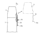
FIG. 15 shows still another reference example of the present invention. In the configuration shown in FIG. 15 , the
上記構成においては、キャップ3の突出部33が、キャップ3とハウジング1とを接続しておくための接続手段に相当することとなり、キャップ3をハウジング1から取り外したときには、突出部33が第2の支持部7Bに支持されていることにより、キャップ3と
ハウジング1との接続状態が維持される。このように、本発明においては、接続手段をキャップ3に一体的に設けてもかまわない。また、このような構成に代えて、接続手段をハウジングに一体的に設けた構成とすることもできる。このような構成によれば、キャップやハウジングとは別体の接続手段を用いる場合と比べて、部品点数を少なくし、製造コストの低減を図るのに好適となる。
In the above configuration, the protruding
本発明でいう接続手段としては、上述した実施形態で用いられていた部材以外として、種々の部材または物品を用いることが可能である。また、本発明においては、キャップとハウジングとの接続に、複数の接続部材を用いてもかまわない。 As the connection means in the present invention, various members or articles can be used in addition to the members used in the above-described embodiments . Also, in the present invention, the connection between the cap and the housing, may be used a plurality of connection members.
ハウジング1の筒部12の外周面12bの基本輪郭を真円にしつつ、キャップ3の筒部32の内周面32aの基本輪郭を、楕円とは異なる長円などの真円以外の円としてもかまわない。さらに、円以外の三角形、四角形、あるいはそれ以外の多角形としてもかまわない。
While the basic contour of the outer
キャップは、円筒状や角筒状などの単なる筒状に形成されていてもよい。穿刺部材としては、上記したランセットとは異なる形態のものを用いることができる。穿刺部材を前進
させるための動作機構は、バネ力を利用したものに限らず、電磁力やエア力を利用したものであってもよく、種々の機構を採用することができる。ハウジングは、必ずしも上記動作機構の全体を内部に収容したものである必要はなく、上記動作機構の一部分を内部に収容するものとして構成されていてもかまわない。
The cap may be formed in a simple cylindrical shape such as a cylindrical shape or a rectangular tube shape. As the puncture member, a member different from the lancet described above can be used. The operation mechanism for advancing the puncture member is not limited to one using spring force, but may be one using electromagnetic force or air force, and various mechanisms can be employed. The housing does not necessarily have to house the entire operation mechanism inside, and may be configured to house a part of the operation mechanism inside.
A,A′ 穿刺装置
1 ハウジング
12 (ハウジングの)筒部(インナ側筒部)
12b (筒部の)外周面(インナ側筒部の外周面)
13 (ハウジングの)係合用凹溝
14 (ハウジングの)領域
2 ランセット(穿刺部材)
3 キャップ
31 (キャップの)開口部
32 (キャップの)筒部(アウタ側筒部)
32a (筒部の)内周面(アウタ側筒部の内周面)
32b (筒部の)外周面(アウタ側筒部の外周面)
33 (キャップの)係合用凸部
34 凸部(目印)
4 ランセットホルダ
5 操作キャップ
7A 第1の支持部
7B 第2の支持部
70 (第1の支持部の)孔部
72 (第2の支持部の)孔部
8 紐(接続部材)
8A〜8D 接続部材
91 イジェクタ(可動体)
91a (イジェクタの)操作部
91b (イジェクタの)第1作用部(追加の作用部)
91c (イジェクタの)第2作用部(作用部)
A, A '
12b Outer peripheral surface (outer peripheral surface of inner side cylindrical portion)
13 Engaging concave groove (of housing) 14 (Housing)
3 cap 31 (cap) opening 32 (cap) cylinder part (outer side cylinder part)
32a (Cylinder part) inner peripheral surface (outer side cylindrical part inner peripheral surface)
32b Outer peripheral surface (outer cylindrical surface) (outer outer cylindrical surface)
33 Projection for engaging (of cap) 34 Projection (mark)
4
8A-8D Connection member 91 Ejector (movable body)
91a (Ejector)
91c Second action part (of the ejector) (action part)
Claims (8)
このハウジングに装着され、かつ上記穿刺部材が前進したときに上記穿刺部材の先端を外部に突出させるための開口部を有するキャップと、
を備えている穿刺装置であって、
上記ハウジングと上記キャップとを接続手段を介して繋げておくことを可能とするために、上記キャップに設けられた第1の支持部および上記ハウジングに設けられた第2の支持部と、を備えており、上記第1の支持部および上記第2の支持部の少なくとも一方は、上記接続手段を抱持する切欠きリング状に形成されていることを特徴とする、穿刺装置。 A housing that houses therein an operation mechanism for advancing the puncture member in a specific direction;
A cap attached to the housing and having an opening for projecting the tip of the puncture member to the outside when the puncture member advances;
A puncture device comprising:
A first support portion provided on the cap and a second support portion provided on the housing in order to allow the housing and the cap to be connected via a connecting means; The puncture apparatus according to claim 1, wherein at least one of the first support part and the second support part is formed in a notch ring shape for holding the connection means.
上記キャップが上記ハウジングから取り外された状態において、上記キャップを上記特定方向と交差する方向に変位させることが可能に構成されている、請求項3または4に記載の穿刺装置。 The connecting means has flexibility,
The puncture apparatus according to claim 3 or 4, wherein the cap is configured to be displaceable in a direction intersecting the specific direction in a state where the cap is removed from the housing .
上記一方の要素はインナ側筒部を有しているとともに、上記他方の要素は上記インナ側筒部に外嵌するアウタ側筒部を有しており、
上記インナ側筒部の外周面と上記アウタ側筒部の内周面とは、上記特定方向から見た場合に、基本輪郭の形状が相違している、請求項1ないし7のいずれかに記載の穿刺装置。 The cap is attached to the housing by fitting one element of the cap and the housing to the other element, and
The one element has an inner cylinder part, and the other element has an outer cylinder part fitted around the inner cylinder part,
The outer peripheral surface and the inner peripheral surface of the outer cylindrical portion of the inner cylindrical portion and, when viewed from the specific direction, the shape of the base profile is you are different, according to any one of claims 1 to 7 Puncture device.
Priority Applications (1)
| Application Number | Priority Date | Filing Date | Title |
|---|---|---|---|
| JP2004151368A JP4801327B2 (en) | 2003-05-21 | 2004-05-21 | Puncture device |
Applications Claiming Priority (5)
| Application Number | Priority Date | Filing Date | Title |
|---|---|---|---|
| JP2003143196 | 2003-05-21 | ||
| JP2003143195 | 2003-05-21 | ||
| JP2003143196 | 2003-05-21 | ||
| JP2003143195 | 2003-05-21 | ||
| JP2004151368A JP4801327B2 (en) | 2003-05-21 | 2004-05-21 | Puncture device |
Related Child Applications (1)
| Application Number | Title | Priority Date | Filing Date |
|---|---|---|---|
| JP2009288641A Division JP4814990B2 (en) | 2003-05-21 | 2009-12-21 | Puncture device |
Publications (3)
| Publication Number | Publication Date |
|---|---|
| JP2005000653A JP2005000653A (en) | 2005-01-06 |
| JP2005000653A5 JP2005000653A5 (en) | 2007-07-05 |
| JP4801327B2 true JP4801327B2 (en) | 2011-10-26 |
Family
ID=34108548
Family Applications (1)
| Application Number | Title | Priority Date | Filing Date |
|---|---|---|---|
| JP2004151368A Expired - Lifetime JP4801327B2 (en) | 2003-05-21 | 2004-05-21 | Puncture device |
Country Status (1)
| Country | Link |
|---|---|
| JP (1) | JP4801327B2 (en) |
Families Citing this family (4)
| Publication number | Priority date | Publication date | Assignee | Title |
|---|---|---|---|---|
| GB2451840B (en) * | 2007-08-14 | 2012-01-18 | Owen Mumford Ltd | Lancing devices |
| GB0715798D0 (en) * | 2007-08-14 | 2007-09-19 | Owen Mumford Ltd | Lancing devices |
| JP2010038601A (en) * | 2008-08-01 | 2010-02-18 | Toyota Motor Corp | Analyzer |
| JP6482303B2 (en) * | 2015-02-05 | 2019-03-13 | テルモ株式会社 | Body moisture meter |
Family Cites Families (17)
| Publication number | Priority date | Publication date | Assignee | Title |
|---|---|---|---|---|
| JPS5854368Y2 (en) * | 1980-04-16 | 1983-12-10 | 和泉電気株式会社 | Hinge for opening and closing container lids |
| JPH0242594Y2 (en) * | 1984-12-19 | 1990-11-14 | ||
| JPH037309Y2 (en) * | 1985-01-16 | 1991-02-22 | ||
| US4620549A (en) * | 1985-01-25 | 1986-11-04 | Becton, Dickinson And Company | Blood collection assembly |
| JPS6319296A (en) * | 1986-07-11 | 1988-01-27 | 遠藤 美義 | Cap missing preventive device for writing utensil |
| JPH0372641A (en) * | 1989-05-09 | 1991-03-27 | Citizen Watch Co Ltd | Ic packaging structure and its packaging method |
| JPH0391630A (en) * | 1989-08-31 | 1991-04-17 | Shimadzu Corp | Air conditioner |
| JP3034448B2 (en) * | 1995-08-24 | 2000-04-17 | 株式会社パイロット | Coating and writing instrument caps |
| JP2673501B2 (en) * | 1995-10-05 | 1997-11-05 | 巴豊 小林 | Writing instrument with cap |
| JPH10118002A (en) * | 1996-10-23 | 1998-05-12 | Olympus Optical Co Ltd | Endoscope |
| JPH10225439A (en) * | 1997-02-17 | 1998-08-25 | Olympus Optical Co Ltd | Image pickup device for endoscope |
| JP4229400B2 (en) * | 1997-02-18 | 2009-02-25 | 株式会社小糸製作所 | Automotive headlamps |
| JPH1170967A (en) * | 1997-08-28 | 1999-03-16 | Yoshino Kogyosho Co Ltd | Cap |
| JPH1170966A (en) * | 1997-08-28 | 1999-03-16 | Yoshino Kogyosho Co Ltd | Cap |
| JPH11206742A (en) * | 1998-01-22 | 1999-08-03 | Terumo Corp | Piercing tool |
| JP4120080B2 (en) * | 1998-12-28 | 2008-07-16 | ソニー株式会社 | Imaging device and lens cap holder |
| JP2002019821A (en) * | 2000-07-05 | 2002-01-23 | Osawa Wax Kk | Lid with coupling member and container coupled with lid |
-
2004
- 2004-05-21 JP JP2004151368A patent/JP4801327B2/en not_active Expired - Lifetime
Also Published As
| Publication number | Publication date |
|---|---|
| JP2005000653A (en) | 2005-01-06 |
Similar Documents
| Publication | Publication Date | Title |
|---|---|---|
| JP4910879B2 (en) | Medical clip device, its elastic clip unit and flexible tube unit | |
| JP6688362B2 (en) | Device for attaching bracelets | |
| US20050265132A1 (en) | Connection structure for a watchcase with a watch chain | |
| KR101755679B1 (en) | Portable object with an interchangeable bracelet or strap | |
| US20060280038A1 (en) | Wristwatch and band timepiece | |
| JP4801327B2 (en) | Puncture device | |
| US7677824B2 (en) | Slide pen | |
| JP4648818B2 (en) | clip | |
| JP4814990B2 (en) | Puncture device | |
| JPWO2010070984A1 (en) | Hood mounting jig | |
| US20160239083A1 (en) | Jewelry-Stylus Device | |
| US20030123689A1 (en) | Microphone holder | |
| TWI572431B (en) | Cut off the tool | |
| JP2006281586A (en) | Interconnecting structure of holder tube | |
| JP6185015B2 (en) | Front glasses | |
| JP4508989B2 (en) | Cleaning tool | |
| WO2016068075A1 (en) | Pipe joint and manufacturing method for pipe joints | |
| JP5041453B1 (en) | Fasteners for jewelry | |
| JP3057709U (en) | Eyeglasses and nose pads for eyeglasses | |
| CN214352130U (en) | Shaft pulling device | |
| JP2011177523A (en) | Puncture apparatus capable of adjusting puncture depth | |
| JP2005185592A (en) | Puncture tool | |
| JP3214692U (en) | Fabric care tools | |
| JP3103041U (en) | Watch band | |
| JPH09271414A (en) | Hand cleaner |
Legal Events
| Date | Code | Title | Description |
|---|---|---|---|
| A521 | Request for written amendment filed |
Free format text: JAPANESE INTERMEDIATE CODE: A523 Effective date: 20070511 |
|
| A621 | Written request for application examination |
Free format text: JAPANESE INTERMEDIATE CODE: A621 Effective date: 20070511 |
|
| A131 | Notification of reasons for refusal |
Free format text: JAPANESE INTERMEDIATE CODE: A131 Effective date: 20091020 |
|
| A521 | Request for written amendment filed |
Free format text: JAPANESE INTERMEDIATE CODE: A523 Effective date: 20091221 |
|
| A131 | Notification of reasons for refusal |
Free format text: JAPANESE INTERMEDIATE CODE: A131 Effective date: 20100831 |
|
| A521 | Request for written amendment filed |
Free format text: JAPANESE INTERMEDIATE CODE: A523 Effective date: 20101101 |
|
| TRDD | Decision of grant or rejection written | ||
| A01 | Written decision to grant a patent or to grant a registration (utility model) |
Free format text: JAPANESE INTERMEDIATE CODE: A01 Effective date: 20110802 |
|
| A01 | Written decision to grant a patent or to grant a registration (utility model) |
Free format text: JAPANESE INTERMEDIATE CODE: A01 |
|
| A61 | First payment of annual fees (during grant procedure) |
Free format text: JAPANESE INTERMEDIATE CODE: A61 Effective date: 20110805 |
|
| FPAY | Renewal fee payment (event date is renewal date of database) |
Free format text: PAYMENT UNTIL: 20140812 Year of fee payment: 3 |
|
| R150 | Certificate of patent or registration of utility model |
Ref document number: 4801327 Country of ref document: JP Free format text: JAPANESE INTERMEDIATE CODE: R150 Free format text: JAPANESE INTERMEDIATE CODE: R150 |
|
| R250 | Receipt of annual fees |
Free format text: JAPANESE INTERMEDIATE CODE: R250 |
|
| R250 | Receipt of annual fees |
Free format text: JAPANESE INTERMEDIATE CODE: R250 |
|
| R250 | Receipt of annual fees |
Free format text: JAPANESE INTERMEDIATE CODE: R250 |
|
| R250 | Receipt of annual fees |
Free format text: JAPANESE INTERMEDIATE CODE: R250 |
|
| R250 | Receipt of annual fees |
Free format text: JAPANESE INTERMEDIATE CODE: R250 |
|
| R250 | Receipt of annual fees |
Free format text: JAPANESE INTERMEDIATE CODE: R250 |
|
| R250 | Receipt of annual fees |
Free format text: JAPANESE INTERMEDIATE CODE: R250 |
|
| R250 | Receipt of annual fees |
Free format text: JAPANESE INTERMEDIATE CODE: R250 |
|
| R250 | Receipt of annual fees |
Free format text: JAPANESE INTERMEDIATE CODE: R250 |
|
| R250 | Receipt of annual fees |
Free format text: JAPANESE INTERMEDIATE CODE: R250 |