JP4800792B2 - Serverless peer-to-peer multi-party real-time voice communication system and method - Google Patents
Serverless peer-to-peer multi-party real-time voice communication system and method Download PDFInfo
- Publication number
- JP4800792B2 JP4800792B2 JP2006047524A JP2006047524A JP4800792B2 JP 4800792 B2 JP4800792 B2 JP 4800792B2 JP 2006047524 A JP2006047524 A JP 2006047524A JP 2006047524 A JP2006047524 A JP 2006047524A JP 4800792 B2 JP4800792 B2 JP 4800792B2
- Authority
- JP
- Japan
- Prior art keywords
- peer
- audio
- mixing
- node
- communication system
- Prior art date
- Legal status (The legal status is an assumption and is not a legal conclusion. Google has not performed a legal analysis and makes no representation as to the accuracy of the status listed.)
- Expired - Fee Related
Links
Images


Classifications
-
- H—ELECTRICITY
- H04—ELECTRIC COMMUNICATION TECHNIQUE
- H04L—TRANSMISSION OF DIGITAL INFORMATION, e.g. TELEGRAPHIC COMMUNICATION
- H04L65/00—Network arrangements, protocols or services for supporting real-time applications in data packet communication
- H04L65/40—Support for services or applications
- H04L65/403—Arrangements for multi-party communication, e.g. for conferences
- H04L65/4046—Arrangements for multi-party communication, e.g. for conferences with distributed floor control
-
- H—ELECTRICITY
- H04—ELECTRIC COMMUNICATION TECHNIQUE
- H04L—TRANSMISSION OF DIGITAL INFORMATION, e.g. TELEGRAPHIC COMMUNICATION
- H04L65/00—Network arrangements, protocols or services for supporting real-time applications in data packet communication
- H04L65/1066—Session management
- H04L65/1101—Session protocols
-
- H—ELECTRICITY
- H04—ELECTRIC COMMUNICATION TECHNIQUE
- H04L—TRANSMISSION OF DIGITAL INFORMATION, e.g. TELEGRAPHIC COMMUNICATION
- H04L67/00—Network arrangements or protocols for supporting network services or applications
- H04L67/01—Protocols
- H04L67/10—Protocols in which an application is distributed across nodes in the network
- H04L67/104—Peer-to-peer [P2P] networks
- H04L67/1074—Peer-to-peer [P2P] networks for supporting data block transmission mechanisms
- H04L67/1076—Resource dissemination mechanisms or network resource keeping policies for optimal resource availability in the overlay network
-
- H—ELECTRICITY
- H04—ELECTRIC COMMUNICATION TECHNIQUE
- H04L—TRANSMISSION OF DIGITAL INFORMATION, e.g. TELEGRAPHIC COMMUNICATION
- H04L67/00—Network arrangements or protocols for supporting network services or applications
- H04L67/01—Protocols
- H04L67/10—Protocols in which an application is distributed across nodes in the network
- H04L67/104—Peer-to-peer [P2P] networks
- H04L67/1074—Peer-to-peer [P2P] networks for supporting data block transmission mechanisms
- H04L67/1078—Resource delivery mechanisms
- H04L67/108—Resource delivery mechanisms characterised by resources being split in blocks or fragments
-
- H—ELECTRICITY
- H04—ELECTRIC COMMUNICATION TECHNIQUE
- H04L—TRANSMISSION OF DIGITAL INFORMATION, e.g. TELEGRAPHIC COMMUNICATION
- H04L69/00—Network arrangements, protocols or services independent of the application payload and not provided for in the other groups of this subclass
- H04L69/04—Protocols for data compression, e.g. ROHC
-
- H—ELECTRICITY
- H04—ELECTRIC COMMUNICATION TECHNIQUE
- H04L—TRANSMISSION OF DIGITAL INFORMATION, e.g. TELEGRAPHIC COMMUNICATION
- H04L12/00—Data switching networks
- H04L12/02—Details
- H04L12/16—Arrangements for providing special services to substations
- H04L12/18—Arrangements for providing special services to substations for broadcast or conference, e.g. multicast
- H04L12/1813—Arrangements for providing special services to substations for broadcast or conference, e.g. multicast for computer conferences, e.g. chat rooms
Abstract
Description
本発明は、一般的には、コンピュータネットワーキングに関し、より具体的には、サーバレスピアツーピア(P2P)マルチパーティリアルタイム音声通信システムおよび方法であって、ピアのそれぞれが、交代して音声をミキシングし、圧縮した音声を再配信(redelivering)するとともに、あるピアによってミキシングおよび再配信される音声フレーム数が、そのピアの利用可能な資源(アップロード帯域幅または計算能力など)に比例する、システムおよび方法に関する。 The present invention relates generally to computer networking, and more particularly to a serverless peer-to-peer (P2P) multi-party real-time voice communication system and method, wherein each of the peers takes turns mixing audio, The present invention relates to systems and methods that redeliver compressed audio and that the number of audio frames that are mixed and redistributed by a peer is proportional to the resources available to that peer (such as upload bandwidth or computing power). .
マルチパーティ音声通信システムは、一群の人がリアルタイム音声通信セッションに参加することを可能にする。さらに、このシステムは、多数の人が同時に話すことを可能にする。(音声キャプチャ、音響エコーキャンセレーション(AEC)、自動ゲインコントロール(AGC)、および音声/通話圧縮などの)ツーパーティ音声通信システムの音声構成要素に加えて、マルチパーティ音声通信システムには、音声ミキシングおよびネットワーク配信における固有の課題がある。 A multi-party voice communication system allows a group of people to participate in a real-time voice communication session. In addition, this system allows many people to speak at the same time. In addition to the voice components of two-party voice communication systems (such as voice capture, acoustic echo cancellation (AEC), automatic gain control (AGC), and voice / call compression), multi-party voice communication systems include voice mixing. And there are inherent challenges in network distribution.
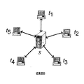
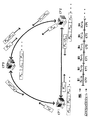
一例として、n個のピアコンピュータ(またはピア)が、起こりうる複数の同時話者とのマルチパーティ音声通信セッションに参加していることを仮定する。さらに、音声の各ストリームは、bwの帯域幅を必要とすると仮定する。マルチパーティ音声通信システムは、様々なトポロジおよびミキシング方策を用いて形成することができる。普及しているトポロジの1つは、図1Aに示すような、スタートポロジである。高性能の中央サーバSは、すべてのピア(t1、t2、t3、t4、およびt5)からの音声ストリームを受信し、この音声ストリームをミキシングし、そしてミキシングおよびリエンコード(re−encode)された音声をすべてのピアに返す。 As an example, assume that n peer computers (or peers) are participating in a multi-party voice communication session with multiple possible concurrent speakers. Further assume that each stream of audio requires bw bandwidth. Multi-party voice communication systems can be formed using various topologies and mixing strategies. One popular topology is a star topology, as shown in FIG. 1A. The high-performance central server S receives audio streams from all peers (t 1 , t 2 , t 3 , t 4 , and t 5 ), mixes the audio streams, and mixes and re-encodes (re -Encoded) returns the audio to all peers.
スタートポロジの利点は、各パーティが、ツーパーティ通信システムのハードウェアと同じハードウェアを使用し、したがって変更を必要としないことである。マルチパーティ通信セッションをサポートするためには、サーバだけを再設計すればよい。結果的に、スタートポロジは、商業用マルチパーティ通信のソリューションとして一般的に選択されている。そのようなシステムの1つが、非特許文献1に記載されている。スタートポロジの主たる欠点は、サーバS上に大きな演算と帯域の負担がかかることである。サーバSは、n個のストリームの圧縮音声(n・bwのダウンロード帯域幅)を受信し、それらをデコード、ミキシング、リエンコードして、ミキシングした音声をn個のピア(n・bwのアップロード帯域幅)に返す必要がある。
The advantage of the star topology is that each party uses the same hardware as that of the two-party communication system and therefore does not require modification. To support multi-party communication sessions, only the server needs to be redesigned. As a result, star topologies are commonly chosen as commercial multi-party communication solutions. One such system is described in Non-Patent
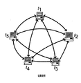
第2の一般的なトポロジは、図1Bに示すような、完全接続ユニキャスト(unicast)ネットワークである。完全接続ネットワークにおいては、すべてのピアがネットワーク内の他のすべてのピアに接続されている。この種のトポロジの一例について、非特許文献2で考察されている。このトポロジにおいては、ピア(t1、t2、t3、t4、およびt5)は、いかなる音声ミキシングも再配信も実行しない。その代わりに、それぞれの話者は、単に、圧縮音声を他のすべてのピアに送信する。そのようなトポロジでは、それぞれのピアは、音声を残りのピアに送信するのに(n−1)・bwのアップロード帯域幅を必要とするとともに、入力音声を受信するのに、最大(n−1)・bwのダウンロード帯域幅を必要とする。このトポロジの1つの欠点は、ネットワークトラフィックの大幅な増加であり、このことは、それぞれのピアおよびネットワーク全体に大きな負担を与える。
The second common topology is a fully connected unicast network as shown in FIG. 1B. In a fully connected network, all peers are connected to all other peers in the network. An example of this type of topology is discussed in Non-Patent
第3の可能なトポロジは、汎用グラフ(generic graph)であり、これはエンドシステムミキシングを使用する。この種のトポロジの一例が、図1Cに示されており、また非特許文献3に記載されている。図1Cに示すように、この例において、ピアa、b、fおよびgは葉ノード(leaf node)であり、いかなるミキシング演算も実行しない。ピアc、dおよびeは、ゲートウェイノードとしての役割を果たし、このゲートウェイノードは、近傍のピアのために音声をミキシングして再配信する。一般に、m個の隣接ノードがあれば、音声を受信して再配信するのに、m・bwのアップロードおよびダウンロード帯域幅を必要とする。mは通常はnよりもずっと小さいので、このトポロジの設計は、大規模会議セッションにうまく対応することができる。しかしながら、このトポロジの欠点は、ゲートウェイノードに対する負担が大きくなる可能性があることである。別の欠点は、ゲートウェイの連鎖が長くなると、音声配信の待ち時間が長くなることである。さらに別の欠点は、配信の連鎖に沿って、音声の同期がずれる可能性もあることである。 A third possible topology is a generic graph, which uses end system mixing. An example of this type of topology is shown in FIG. 1C and described in Non-Patent Document 3. As shown in FIG. 1C, in this example, peers a, b, f and g are leaf nodes and do not perform any mixing operations. Peers c, d, and e serve as gateway nodes, which mix and redistribute voice for neighboring peers. In general, if there are m adjacent nodes, m · bw upload and download bandwidth is required to receive and redistribute audio. Since m is usually much smaller than n, this topology design can accommodate large conference sessions well. However, the disadvantage of this topology is that it can increase the burden on the gateway node. Another drawback is that the longer the gateway chain, the longer the latency of voice delivery. Yet another drawback is that voices may be out of sync along the distribution chain.
音声通信セッションにおけるトラフィックをさらに低減するネットワークレベルのソリューションの1つは、IPマルチキャストによるものである。IPマルチキャストにおいては、ソースから伝送される単一パケットが、そのソースをルートとする配送木(distribution tree)に沿った、ルータ群において複製される。このようにして、コンテンツが任意の数の受信者に配信される。例えば、図1Aに示すスタートポロジにおいて、ピアはユニキャストを経由してサーバに圧縮音声を送信することもできる。しかしながら、サーバSは、ミキシングおよびリエンコードした音声をn個のピアにマルチキャストして返すことができる。そのようなシステムのサンプル実現形態は非特許文献4に記載されている。サーバSのアップロード帯域幅はbwに縮小される。 One network level solution that further reduces traffic in voice communication sessions is through IP multicast. In IP multicast, a single packet transmitted from a source is duplicated in a group of routers along a distribution tree rooted at the source. In this way, content is distributed to any number of recipients. For example, in the star topology shown in FIG. 1A, the peer can also send compressed audio to the server via unicast. However, the server S can multicast and return the mixed and re-encoded audio to n peers. A sample implementation of such a system is described in Non-Patent Document 4. The upload bandwidth of the server S is reduced to bw.
しかしながら、IPマルチキャストの1つの欠点は、サーバのダウンロード帯域幅に対する要求条件が、n・bwで一定のままとなることである。図1Bに示す、完全接続ネットワークにおいて、それぞれの話者は、ネットワークの他のすべてのピアに圧縮音声をマルチキャストすることもできる。ここでも、完全接続ネットワークに対する、IPマルチキャストの欠点は、ピアのアップロード帯域幅がbwに縮小されるのに対して、ピアのダウンロード帯域幅は、(n−1)・bwで一定のままであることである。IPマルチキャストの別の欠点は、とりわけ、ドメイン間ルーティングプロトコル、ISPビジネスモデル(課金モデル)、配送木に沿った輻輳制御(congestion control)、およびセキュリティなどの問題が理由で、その展開が実世界においては遅いことである。その結果として、ある限られた大学/企業サブネットおよび(インターネット2などの)ネットワークテストベッドを除いて、固有IPマルチキャストのサポートは広く普及していない。ネットワークレベルのマルチキャストサービスの展開におけるこれらの問題のために、今日のインターネットにおける大部分のトラフィックは、ユニキャストベースであり、それによって2つのコンピュータが互いに直接話し合う。 However, one drawback of IP multicast is that the requirements for server download bandwidth remain constant at n · bw. In the fully connected network shown in FIG. 1B, each speaker can also multicast the compressed voice to all other peers in the network. Again, the drawback of IP multicast for fully connected networks is that the peer upload bandwidth is reduced to bw, while the peer download bandwidth remains constant at (n-1) · bw. That is. Another disadvantage of IP multicast is that it is deployed in the real world because of issues such as inter-domain routing protocols, ISP business model (billing model), congestion control along the delivery tree, and security, among others. Is slow. As a result, specific IP multicast support is not widely spread except for certain limited university / corporate subnets and network testbeds (such as the Internet 2). Because of these problems in the deployment of network level multicast services, most traffic on the Internet today is unicast based, whereby two computers talk directly to each other.
P2Pネットワークによるファイル転送のための1対多数コンテンツ配布のシステムおよび方法の1種が、2004年7月7日付出願、J.Li、P.ChouおよびC.Zhangの「Efficient One-to-Many Content Distribution in a Peer-to-Peer Computer Network」という名称の米国特許出願第10/887,406に記載されている。しかしながら、その研究では、1対多数ファイル転送および配布を含むが、音声通信セッションは、多数対多数配布を要する。さらに、その研究では、TCP/IPキューを広範囲に使用している。しかしながら、キューの使用は音声会議には実際的ではなく、それはパケットがタイムリーに到着しなくてはならないからである。さらに、異なるソースからの音声がミキシングされる可能性があり、このために、音声配信は、音声通信応用において独特のものとなっている。 One type of one-to-many content distribution system and method for file transfer over a P2P network was filed on Jul. 7, 2004, J.A. Li, P.I. Chou and C.I. Zhang's US application Ser. No. 10 / 887,406, entitled “Efficient One-to-Many Content Distribution in a Peer-to-Peer Computer Network”. However, while that work involves one-to-many file transfer and distribution, voice communication sessions require many-to-many distribution. In addition, the study uses TCP / IP queues extensively. However, the use of queues is impractical for audio conferencing because packets must arrive in a timely manner. In addition, audio from different sources can be mixed, which makes audio distribution unique in audio communication applications.
既存のマルチパーティ音声通信システムの欠点の1つは、ピアまたはサーバが果たすミキシングおよび再配信の役割が、ネットワークトポロジによって固定されていることである。既存音声通信システムの別の欠点は、音声ストリーム全体のミキシングを実行することである。したがって、必要とされるのは、ネットワーク資源を最も効率よく使用する、音声通信システムおよび方法である。さらに、必要とされるのは、上記のネットワークトポロジの欠点を回避するとともに、ピアが果たすミキシングおよび再配信の役割においてフレキシブルであるシステムおよび方法である。さらに、必要とされるのは、音声ストリーム全体ではなく、音声ストリームのフレームに対してミキシングを実施する、音声通信システムおよび方法である。さらに、必要とされるのは、キューの使用を回避して、ファイル転送技法の遅延問題を克服する、音声通信システムおよび方法である。 One disadvantage of existing multi-party voice communication systems is that the role of mixing and redistribution played by peers or servers is fixed by the network topology. Another drawback of existing voice communication systems is that they perform mixing of the entire voice stream. Therefore, what is needed is a voice communication system and method that uses network resources most efficiently. Further, what is needed is a system and method that avoids the shortcomings of the network topologies described above and is flexible in the mixing and redistribution role played by the peers. Further, what is needed is an audio communication system and method that performs mixing on frames of an audio stream rather than the entire audio stream. Furthermore, what is needed is a voice communication system and method that avoids the use of queues and overcomes the delay problems of file transfer techniques.
本明細書において開示する発明は、リアルタイムマルチパーティ音声通信セッションを最大効率で提供するピアツーピア(P2P)音声通信システムおよび方法を含む。P2Pネットワークは、各コンピュータが概して等価な能力と責任を有する種類のネットワークである。P2P音声通信システムおよび方法では、圧縮音声がパケットに区分され、そのパケットのそれぞれが、ミキシングと再配信のために単一ピアに送信される。あるピアによってミキシングおよび再配信されるパケット数は、そのピアの利用可能な資源に比例する。これらの資源には、アップロード帯域幅を含めてもよい。あるいは、資源には、計算能力を含めることもできる。P2P音声通信システムおよび方法は、マルチパーティ音声通信セッションにおいて要求される帯域幅を低減する。さらに、P2P音声通信システムおよび方法では、音声サービス負担とピアアップロード帯域幅を均衡させて、P2Pネットワーク内のすべての参加ピア間でマルチパーティ通信セッションのコストを再分配する。これによって、P2P音声通信システムおよび方法では、高性能のサーバまたはピアを必要とすることなく、マルチパーティ音声通信セッションを実施することが可能となる。 The invention disclosed herein includes peer-to-peer (P2P) voice communication systems and methods that provide real-time multi-party voice communication sessions with maximum efficiency. A P2P network is a type of network in which each computer has generally equivalent capabilities and responsibilities. In a P2P voice communication system and method, compressed voice is segmented into packets, each of which is sent to a single peer for mixing and redistribution. The number of packets mixed and redistributed by a peer is proportional to the resources available to that peer. These resources may include upload bandwidth. Alternatively, resources can include computational power. P2P voice communication systems and methods reduce the bandwidth required in multi-party voice communication sessions. In addition, the P2P voice communication system and method rebalances the cost of multi-party communication sessions among all participating peers in the P2P network by balancing voice service burden and peer upload bandwidth. This allows the P2P voice communication system and method to conduct multi-party voice communication sessions without the need for high performance servers or peers.
ミキシングおよび再配信がネットワークトポロジに基づいている従来技法とは異なり、本明細書に開示するP2P音声通信システムおよび方法では、圧縮音声をパケットまたはフレームに分割(split)または区分(divide)して、それぞれのピアに交代で音声パケットのミキシングおよび再配信を行わせる。P2P音声通信システムおよび方法では、ピアのネットワーク帯域幅負荷を柔軟に均衡させることによって、より多くの資源を有するピアが少ない資源を有するピアを支援できるようになる。さらにP2P音声通信システムおよび方法では、音声ミキシングにより、マルチパーティリアルタイム音声通信システムセッションを行うのに必要な帯域幅が減少する。 Unlike conventional techniques where mixing and redistribution are based on network topology, the P2P voice communication system and method disclosed herein splits or divides compressed voice into packets or frames, and Have each peer take turns mixing and redistributing voice packets. The P2P voice communication system and method allows a peer with more resources to support a peer with fewer resources by flexibly balancing the network bandwidth load of the peers. Furthermore, in P2P voice communication systems and methods, voice mixing reduces the bandwidth required to conduct a multi-party real-time voice communication system session.
本発明は、以下の説明と本発明の態様を示す添付の図面とを参照することによってより詳細に理解されるであろう。一例として本発明の原理を図示する添付の図面を合わせると、以下に示す本発明の詳細の説明から、その他の特徴および利点は明白になるであろう。 The invention will be understood in greater detail by reference to the following description and the accompanying drawings that illustrate aspects of the invention. Other features and advantages will become apparent from the following detailed description of the invention when taken in conjunction with the accompanying drawings which illustrate, by way of example, the principles of the invention.
図面を参照するが、これらの図面では、同じ参照番号は全体を通して対応する部分を表わしている。 Reference is made to the drawings, wherein like reference numerals represent corresponding parts throughout.
本発明の以下の説明において、添付の図面を参照するが、それらは本発明の一部を形成するものであり、それには、一例として、それによって本発明を実施することができる特定の例を示してある。ここで理解すべきことは、本発明の範囲から逸脱することなく、その他の実施形態も利用することが可能であり、また構造的変更も行うことができることである。 In the following description of the invention, reference will be made to the accompanying drawings, which form a part hereof, and by way of illustration, are specific examples by which the invention may be practiced. It is shown. It should be understood that other embodiments may be utilized and structural changes may be made without departing from the scope of the present invention.
I.序文
ピアツーピア(P2P)コンピュータネットワークにおける現行の1対多数配布技法は、コンテンツをソースノードからピアノードに直接送るよりも、より効率的であるが、これらの技法は、ネットワークにおける最も効率的なコンテンツ配布を達成することができない。これにはいくつかの要因がある。1つの要因は、これらの技法には、ピアノード間の帯域幅の差を適切に説明してそれに適応するものが1つもないことである。別の要因は、これらの技法では、コンテンツを配布するときに、ネットワーク上のすべてのピアノードの帯域幅能力を完全に利用することができないことである。
I. Introduction Current one-to-many distribution techniques in peer-to-peer (P2P) computer networks are more efficient than sending content directly from the source node to the peer nodes, but these techniques provide the most efficient content distribution in the network. Cannot be achieved. There are several factors in this. One factor is that none of these techniques adequately account for and adapt to bandwidth differences between peer nodes. Another factor is that these techniques do not fully utilize the bandwidth capabilities of all peer nodes on the network when distributing content.
本明細書において説明する、P2P音声通信システムおよび方法は、マルチパーティ音声通信セッションを実行するための新規な解決策である。P2P音声通信システムおよび方法の重要な特徴は、音声ミキシングおよび音声の再配信の作業が、ミューチュアルキャストクリーク(MutualCast clique)内のピア間で交代して行われることである。ミューチュアルキャストクリークは、完全接続メッシュを形成する、少数のピアノードを含む。音声ミキシングを変換ドメイン上でフレームバイフレーム方式で実行することができるという、波形コード化音声(waveform coded audio)の固有の特性を使用して、このP2P音声通信システムおよび方法では、参加ピア間でミキシングおよび再配信のタスクを交代させる。これによって、ネットワーク帯域幅と計算負荷を共有することができる。このようにして、P2P音声通信システムおよび方法では、高性能のサーバなしに、マルチパーティ音声通信セッションを行うことができる。 The P2P voice communication system and method described herein is a novel solution for performing multi-party voice communication sessions. An important feature of the P2P voice communication system and method is that the work of voice mixing and voice redistribution takes place between peers in a MutualCast clique. Mutual cast creeks contain a small number of peer nodes that form a fully connected mesh. Using the inherent property of waveform coded audio that voice mixing can be performed on a transform domain on a frame-by-frame basis, this P2P voice communication system and method can be used between participating peers. Alternate mixing and redistribution tasks. This allows sharing of network bandwidth and computational load. In this way, the P2P voice communication system and method can perform a multi-party voice communication session without a high-performance server.
II.全体概要
図2は、本明細書において開示するP2P音声通信システムおよび方法の例証的実施形態を示すブロック図である。ここで留意すべきことは、図2は、P2P音声通信システムを実施して使用することのできる、いくつかの方法の内の1つにすぎないことである。
II. General Overview FIG. 2 is a block diagram illustrating an exemplary embodiment of the P2P voice communication system and method disclosed herein. It should be noted here that FIG. 2 is only one of several ways that a P2P voice communication system can be implemented and used.
図2を参照すると、完全接続ピアツーピア(P2P)ネットワーク200が、この例証的実施形態に示してある。P2P音声通信システムおよび方法を実行するP2Pネットワーク200は、ミューチュアルキャストクリークとも呼ばれる。図2に示すこの例証的実施形態において、ミューチュアルキャストクリーク200は、3つのピアノード、すなわちピアノード(1)、ピアノード(2)、およびピアノード(3)を含む。ピアノード(1)、(2)、(3)は、矢印で示すように完全接続されている。ピアノード(1)、(2)、(3)のそれぞれは、P2P音声通信システムおよび方法を含む。
Referring to FIG. 2, a fully connected peer-to-peer (P2P)
図3は、図2に示すようなピアノードのそれぞれに含まれるP2P音声通信システム300の一般的な例証的実現形態を示す詳細ブロック図である。図3を参照すると、一般に、P2P音声通信システム300は、各ピアからのネットワーク音声およびローカルピアからのマイクロフォン入力を受信し、その音声をミキシングして、ミックス音声をピアノードならびにローカルピアに出力する。そのローカルピアノードは、そのミックス音声をミキシングして再配信する。ピアノードの少なくとも一部は、ラウンドロビン(round robin)方式で、ミキシングおよび再配信を交代で実行する。
FIG. 3 is a detailed block diagram illustrating a general illustrative implementation of a P2P
具体的には、図3はローカルピアノード(図示せず)上のP2P音声通信システム300を示す。このP2PネットワークにN個のピアノードがあると仮定する。システム300への入力には、ピア(1)310からピア(N)315までの、ネットワーク音声が含まれる。図3における省略符号は、ピアノードのすべては図示していないことを示している。さらに、マイクロフォンストリーム320も、システム300への入力である。マイクロフォンストリーム320は、ローカルピア上の1つまたは複数のマイクロフォンからのものである。P2P音声通信システム300は、入力音声をフレームまたはパケットに区分して、パケットのそれぞれをあるフレームにおいてミキシングする音声ミキサ330を含む。
Specifically, FIG. 3 shows a P2P
ピア(1)310からのエンコードネットワーク音声は、エントロピーデコード(entropy decoding)および逆量子化(1)340を実行することによって処理される。以下に詳細を説明するように、これによってピア(1)310からのエンコードネットワーク音声が部分的にデコードされて、MDCT変換係数のブロックが生成される。同様に、それぞれのピアからピア(N)315へのエンコードネットワーク音声は、エントロピーデコードおよび逆量子化(N)345を実行することによって処理される。ここでも、図3における省略記号は、エントロピーデコードおよび逆量子化のすべては図示されていないことを示す。マイクロフォンストリームは、変形離散コサイン変換(MDCT:modified discrete cosine transform)モジュール350を使用して処理されて、MDCT変換係数が生成される。
The encoded network speech from peer (1) 310 is processed by performing entropy decoding and inverse quantization (1) 340. As will be described in detail below, this partially decodes the encoded network audio from peer (1) 310 to generate a block of MDCT transform coefficients. Similarly, the encoded network speech from each peer to peer (N) 315 is processed by performing entropy decoding and inverse quantization (N) 345. Again, the ellipsis in FIG. 3 indicates that not all entropy decoding and inverse quantization are shown. The microphone stream is processed using a modified discrete cosine transform (MDCT)
音声ミキサは、ピア(1)から(N)までのネットワーク音声からの音声コンテンツおよびマイクロフォンストリーム320をミキシングするのに使用される。これによってミックス音声パケットが生成される。このミックス音声コンテンツは、ピア(1)360へのミックス音声として、ピア(N)へのミックス音声として、および、省略記号で示すように、その他のピアに対するミックス音声として再配信される。
The audio mixer is used to mix audio content and
ピア(1)からピア(N)の配信されたネットワーク音声は、ローカル再生のためにもミキシングされる。次いで、(ローカル入力が他のピアによってミキシングされている場合には)ローカルマイクロフォン入力コンテンツを引いたミックス音声が、逆MDCTモジュール370に送り込まれる。これによって、ネットワークピアの音声コンテンツが回復されて、スピーカ380を介して再生することが可能となる。
The distributed network audio from peer (1) to peer (N) is also mixed for local playback. The mixed audio minus the local microphone input content is then fed into the inverse MDCT module 370 (if the local input is being mixed by another peer). As a result, the audio content of the network peer is recovered and can be played back via the
ここで留意すべきことは、その他のピアからの音声は、P2Pネットワーク上で伝送される前にエンコードされることである。さらに、ミックス音声コンテンツがピアノードによって受信されると、そのピアは、ミックス音声をデコードして、音声通信セッションに関連する音声を回復する。したがって、ピアノードのそれぞれが、音声ミキサ330を包含する。さらに、音声ミキサ330は、複数の音声エンコーダおよび音声デコーダ構成要素をさらに包含する。いつどのように、これらの構成要素のそれぞれを使用するかは、任意の時間にピアが行っている処理によって決まる。例えば、ローカルピアがミキシングおよび再配信を実行しているときには、音声ミキサ330は、ミューチュアルキャストクリーク内の各ピアから1フレームのエンコード音声を受け取り、部分デコードを実行し、音声をミキシングして、部分エンコードを実行し、1フレームのミックス音声を各ネットワークピアに送る。そのローカルピアがクライアントピアとなり、ミキシングおよび再配信が別のピアに割り当てられるときには、音声ミキサ330は、単に1フレームのエンコードマイクロフォンストリーム入力を、ミキシングを担当するピアに送り、ミキシングピアから1フレームを受け取り、デコード演算を実行し、ローカルにミックス音声を再生する。P2P音声通信システムおよび方法が使用するラウンドロビン方式は、ローカルピアノードの機能を順繰りで迅速に変更するので、構成要素間の必要なスイッチングは迅速に行われる。音声ミキサ330、音声エンコーダ、音声デコーダの詳細を以下に説明する。
It should be noted that voice from other peers is encoded before being transmitted over the P2P network. Further, when the mixed audio content is received by the peer node, the peer decodes the mixed audio to recover the audio associated with the audio communication session. Accordingly, each of the peer nodes includes an
III.動作の概要
図3に示すP2P音声通信システム300の動作について、次に説明する。図4は、図3に示すP2P音声通信システム300の一般的動作を示す一般的フロー図である。一般に、本P2P音声通信方法は、入力音声ストリームをフレームまたはパケットに区分して、フレームの処理を、P2Pネットワーク内のピアノードの間で交代させて行う。より具体的には、本方法は、入力音声ストリームを複数のフレーム(ボックス400)に区分することから始まる。次に、P2Pネットワーク内のピアノードの1つが選択される(ボックス410)。
III. Outline of Operation Next, the operation of the P2P
選択されたピアノードは、その選択されたノードの利用可能な資源に比例するフレームを処理するように割り当てられる(ボックス420)。言い換えると、大量の資源を有するピアノードには、より多数のフレームが割り当てられるのに対して、少量の資源を有するピアノードには、より少数のフレームが割り当てられる。各ピアノードは、交代してフレームを処理する。処理には、入力音声ストリーム内の音声コンテンツのミキシングおよびピアノードへの音声の再配信が含まれる。すなわち、選択されたピアノードは、音声フレームのミキシングを実行して、ミックス音声フレームをP2Pネットワーク内のその他のピアノードに再配信する。フレーム処理は、ピアノード間で交代して行われる(ボックス430)。好ましい実施形態では、この交代は、各ノードに順番が回るように、ラウンドロビン方式または方法で実行される。 The selected peer node is assigned to process a frame that is proportional to the available resources of the selected node (box 420). In other words, a peer node having a large amount of resources is assigned a larger number of frames, whereas a peer node having a small amount of resources is assigned a smaller number of frames. Each peer node takes turns to process the frame. Processing includes mixing audio content in the input audio stream and redistributing audio to peer nodes. That is, the selected peer node performs audio frame mixing and redistributes the mixed audio frame to other peer nodes in the P2P network. Frame processing is alternated between peer nodes (box 430). In a preferred embodiment, this alternation is performed in a round robin fashion or method so that each node is in turn.
IV.動作の詳細および実用例
図3および図4に示すP2P音声通信システムおよび方法の動作の詳細についてここで考察する。本明細書に開示するP2P音声通信システムおよび方法をより詳細に理解するために、例証的な実用例の動作の詳細を提示する。ここで留意すべきことは、この実用例は、P2P音声通信システムおよび方法を実現することのできる1つの方法にすぎないことである。
IV. Details of Operation and Practical Examples Details of the operation of the P2P voice communication system and method shown in FIGS. In order to more fully understand the P2P voice communication system and method disclosed herein, details of the operation of an illustrative practical example are presented. It should be noted that this practical example is only one way in which the P2P voice communication system and method can be implemented.
音声コンテンツ
(波形コード化音声のミキシング)
この実用例においては、P2P音声通信システムおよび方法の音声は、波形コーデックを用いてエンコードされている。そのような波形コーデックに非特許文献5がある。代替コーデックとしては非特許文献6がある。さらなる代替コーデックとしては、ウィンドウズ(登録商標)メディアオーディオ(Windows(登録商標) Media Audio)(非特許文献7)がある。図5は、本実用例において使用される音声エンコーダ500の動作の詳細ブロック/フロー図である。
Audio content (mixing of waveform-coded audio)
In this practical example, the audio of the P2P audio communication system and method is encoded using a waveform codec. There is Non-Patent Document 5 as such a waveform codec. There is Non-Patent Document 6 as an alternative codec. A further alternative codec is Windows (registered trademark) Media Audio (Non-patent Document 7). FIG. 5 is a detailed block / flow diagram of the operation of the speech encoder 500 used in this practical example.
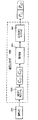
図5を参照すると、音声波形を含む音声入力510は、最初に、フレームに分割または区分される。この実用例において、各フレームの長さは、約20ミリ秒(ms)であった。ここで留意すべきことは、フレーム間に50%の重複があるために、全アルゴリズム遅延は40msであり、フレームのそれの2倍であることである。しかしながら、それぞれの量子化およびエントロピーコード化されたフレーム係数の長さは、依然として20msである。次に、各フレームは、変形離散コサイン変換(MDCT)モジュール520によって係数ブロック(Ci,j)に変換される。添え字iはピアを示し、添え字jはフレーム番号を示す。すなわち、図5において、係数ブロックCi,1はi番目のピアの第1フレームを、係数ブロックCi,2はi番目のピアの第2フレームを示す。次に、係数ブロックは、量子化器530に送られて、量子化される。次いで、この量子化係数ブロックは、エントロピーエンコーダ540によって、パケットpi,jにエントロピーエンコード(entropy encoded)される。図5において、エンコードパケットPi,1およびPi,2は、i番目のピアの第1および第2のフレームに対するエンコードパケットを示す。
Referring to FIG. 5, an
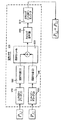
MDCTは線形演算であるので、波形コード化音声は、変換ドメインにおいてのミキシングができるだけでなく、フレーム毎にミキシングすることもできる。図6は、この実用例において使用される音声ミキサ600の動作の詳細ブロック/フロー図である。図6に、2つの圧縮音声パケットからなる、あるフレームのミキシングを示してある。一般に、音声ミキサ600は、あるフレームの圧縮音声パケットをデコードして係数ブロックを得て、係数ブロックを結合し、ブロックをリエンコードし、1フレームの音声に対する単一の圧縮音声パケットを得る。P2P音声通信システムおよび方法の音声ミキシング技法では、現行の音声会議システムにおいて行われるように、入力音声ストリーム全体についてのミキシング演算を実行するのではなく、音声のフレームをミキシングする。
Since MDCT is a linear operation, the waveform-coded speech can be mixed not only in the transform domain but also on a frame-by-frame basis. FIG. 6 is a detailed block / flow diagram of the operation of the
特に、この実用例においては、エントロピーデコーダ(1)610および逆量子化器(1)620を使用して、圧縮音声パケットP1,jがデコードされて、あるピアに対する係数ブロックが得られる。同様に、エントロピーデコーダ(2)630および逆量子化器(2)640を使用して、圧縮音声パケットP2、jがデコードされて、別のピアに対する係数ブロックを得られる。結果として得られる係数は、MDCT変換係数である。これらのMDCT変換係数は、結合モジュール650を使用して、結合モジュール650中の「+」記号で表わすように互いに加算されるか、または結合される。ここで留意すべきことは、図6には音声に対して「+」記号を示してあるが、結合は、減算(マイナス符号「−」)としても加算(プラス符号「+」)としてもよく、エンコード音声に対する聴覚上の差異はないということである。次に、結果として得られる係数ブロックは、ミキシング量子化器660を使用して量子化されて、それからミキシングエントロピーエンコーダ670を使用してエントロピーリエンコードされる。これによって、ミックス音声パケットP1,j+P2、jを含む、フレームが生成される。このミキシング工程中に、その他のいずれのフレームの音声パケットにも、アクセスはなかった。
In particular, in this practical example, compressed speech packet P 1, j is decoded using entropy decoder (1) 610 and inverse quantizer (1) 620 to obtain a coefficient block for a peer. Similarly, using the entropy decoder (2) 630 and inverse quantizer (2) 640, the compressed speech packet P2 , j is decoded to obtain a coefficient block for another peer. The resulting coefficient is the MDCT conversion coefficient. These MDCT transform coefficients are added together or combined using the combining
図7は、この実用例において使用される音声デコーダ700の動作の詳細ブロック/フロー図である。受信器において、ミキシングされたパケットは、正常にデコードされた。図7を参照すると、ミックス音声パケットP1,j+P2、jは、音声デコーダ700に入力された。各フレームは、エントロピーデコーダ(3)710によって、次いで逆量子化器(3)720によって処理された。これによって、ミキシングされたMDCT変換係数、C1,1+C2,1およびC1,2+C2,2が生成された。次に、ミキシングされたMDCT変換係数は、逆MDCTモジュール730を使用して処理された。結果として得られた出力は、ピア1およびピア2からの、ミックス音声波形(音声1+音声2)740であった。
FIG. 7 is a detailed block / flow diagram of the operation of the audio decoder 700 used in this practical example. At the receiver, the mixed packet was successfully decoded. Referring to FIG. 7, the mixed audio packet P 1, j + P 2, j is input to the audio decoder 700. Each frame was processed by entropy decoder (3) 710 and then by inverse quantizer (3) 720. This produced mixed MDCT transform coefficients, C 1,1 + C 2,1 and C 1,2 + C 2,2 . The mixed MDCT transform coefficients were then processed using an
(音声コンテンツのラウンドロビン式交代ミキシングおよび再配信)
この実用例における別の構成要素は、ラウンドロビン方式による音声コンテンツの交代ミキシングと再配信であった。言い換えると、ピアのそれぞれが、交代で音声コンテンツをミキシングおよび再配信した。この実用例においては、完全接続メッシュを形成する少数のピアノードからなる、ミューチュアルキャストクリークを使用した。波形コード化音声コンテンツは、フレームバイフレーム方式でミキシングすることができるという特性を使用して、P2P音声会議システムおよび方法では、ミキシングおよび再配信演算がピア間で交代で行われた。これによって、最も効率的な方法で、帯域幅および計算負荷が適当に配分されることが確実になった。好ましい実施形態では、この交代は、ラウンドロビン方式および/または方法で行われ、それによって各ピアノードが交代して音声をミキシングして再配信した。
(Round-robin alternation mixing and redistribution of audio content)
Another component in this practical example was alternating mixing and redistribution of audio content in a round robin manner. In other words, each of the peers took turns mixing and redistributing the audio content. In this practical example, a mutual cast clique consisting of a small number of peer nodes forming a fully connected mesh was used. Using the property that waveform-encoded audio content can be mixed on a frame-by-frame basis, in the P2P audio conferencing system and method, mixing and redistribution operations were performed between peers. This ensured that bandwidth and computational load were properly allocated in the most efficient manner. In the preferred embodiment, this alternation is done in a round robin fashion and / or method, whereby each peer node takes turns to mix and redistribute the audio.
図8は、この実用例において使用された、3つのピアノード(1、2および3)に対する音声ミキシングセッションを示す。音声ミキシングスケジュールを図8の下部に示してある。この音声ミキシングスケジュールを参照すると、ピアノード1、2、3は、それぞれ、フレーム3k、3k+1、3k+2において音声ミキシングおよび再配信を担当した。すなわち、1番目のフレームにおいて、ピア2が音声パケットのミキシングおよび再配信を行った。図8に示すように、ピア2がミキシングおよび再配信を担当している間、ピア1およびピア3は、それらのエンコード音声P1,1およびP3,1をピア2に送った。次いで、入力音声パケットは、エントロピーデコードおよび逆量子化を経て、MDCT係数C1,1およびC3,1に戻された。次いで、ピア2は、それ自体の係数C2,1を加えた。次いで、ミックス音声は、ピア1およびピア3に送り返された。
FIG. 8 shows an audio mixing session for the three peer nodes (1, 2 and 3) used in this practical example. The audio mixing schedule is shown at the bottom of FIG. Referring to this voice mixing schedule,
エコーを回避するために、ソース音声はミキシングせずに、送り返された。言い換えると、図8を参照すると、ピア2は、係数C1,1およびC2,1を加算して、この係数の合計を量子化およびエントロピーエンコードした。次いで、ピア2はミックスパケットP1,1+P2,1をピア3に送り返した。同様に、ミックスパケットP3,1+P2,1はピア2によってピア1に送られた。目的地において、異なるピアからのミックス音声パケットは、ソートされ、エントロピーデコードされ、再生のために、逆量子化および逆MDCT変換された。
To avoid echo, the source audio was sent back without mixing. In other words, referring to FIG. 8,
再び、図8のミキシングスケジュールを参照すると、第2フレームにおいて、ピア3がミキシングの役割についた。ピア1およびピア2は、2番目のフレームにおけるそれらの圧縮音声パケットP1,2およびP2,2をピア3に送った。次いで、ピア3は入力音声パケットを、それ自体の係数C3,2とミキシングした。次いで、ピア3は、ミックスパケットP3,2+P2,2をピア1に送り、ミックスパケットP3,2+P1,2をピア2に送った。
Referring again to the mixing schedule of FIG. 8, in the second frame, peer 3 took on the role of mixing.
図8に示すように、3番目のフレームにおいて、ピアノード1がミキシングノードとなり、以下同様であった。ミキシングおよび再配信のタスクをタイムシェアリングすることによって、ミキシングの帯域幅および計算コストは、ピアのそれぞれの間に分配される。その結果として、サーバを必要とすることなく、1群の低性能のピアによって、マルチパーティ音声通信セッションを行うことができる。
As shown in FIG. 8, in the third frame, the
P2P音声通信システムおよび方法では、ミューチュアルキャストクリークはn個のノードからなる。各ピアノードは、2(n−1)個のパケットをnフレーム毎に送受信する。その中で、(n−1)個のパケットは、それがミキシング演算を実行しないn−1個のフレームの間に送受信される。さらに、(n−1)個のパケットが、それがミキシングおよび再配信の演算を実行する間に、送受信される。したがって、アップロード/ダウンロードに必要な帯域幅は、(2−2/n)・bwである。また、平均して、(2−2/n)個のストリームの音声が各ピアによってデコード、リエンコードされるということも計算することができる。ミキシングの間に、ピアは、(n−1)回のエントロピーデコードおよび逆量子化の演算、および(n−1)回の前方量子化およびエントロピーエンコードの演算を実行する。 In the P2P voice communication system and method, the mutual cast clique consists of n nodes. Each peer node transmits and receives 2 (n-1) packets every n frames. Among them, (n-1) packets are transmitted and received during n-1 frames where it does not perform a mixing operation. In addition, (n-1) packets are sent and received while it performs mixing and redistribution operations. Therefore, the bandwidth required for upload / download is (2-2 / n) · bw. It can also be calculated that, on average, (2-2 / n) streams of audio are decoded and re-encoded by each peer. During mixing, the peer performs (n-1) entropy decoding and inverse quantization operations and (n-1) forward quantization and entropy encoding operations.
再配信されたミックス音声パケットに含まれるコンテンツに関して、少なくとも2つの可能性がある。好ましい一実施形態においては、ミックス音声パケットは、ソース(または選択された)ピアノードの音声コンテンツは含まない。言い換えると、交代音声ミキシング技法は、あるピアのソース音声をミキシングせず、かつ送り返さないことを含む。一代替実施形態においては、ミックス音声パケットは、ピアノードのそれぞれからの音声コンテンツを含み、そのミックス音声パケットからそれ自体の音声コンテンツを差し引くのは、各ピアに任されている。例えば、ミックス音声は、フレームjに対してパケット(mj=p1,j+p2,j+p3,j)を含む。次いで、同じミックス音声がすべてのピアに返送される。エコーを低減または除去するために、各ピアには、そのミックス音声からそれ自体の音声を差し引く責任がある。例えば、ピアiはmjからpi,jを差し引き、それは加算の代わりに減算によるミキシング演算である。この代替実施形態の利点は、ピアは、ミキシング中に一回の前方量子化およびエントロピーエンコード演算を実行する必要があるだけであることである。さらに、IPマルチキャストがすべてのピア間でサポートされている場合には、ミキシングピアは、ミックスパケットを残りのピアにマルチキャストすることができる。この代替実施形態の欠点は、ミックス音声は、量子化してエントロピーエンコードする必要があるために、ミックスパケットmj内の構成音声pi,jが、ピアiが保持する音声pi,jと異なることである。したがって、残留エコーが残る可能性がある。この残留エコーは、ピアの数の増加および/またはミックス音声のコーディングビットレートの減少とともにより明白になる。したがって、この残留エコー問題のため、音声パケットのすべてをミックスしない実施形態が好ましい。 There are at least two possibilities for the content contained in the redistributed mixed audio packet. In a preferred embodiment, the mixed audio packet does not include the audio content of the source (or selected) peer node. In other words, alternate voice mixing techniques include not mixing and sending back a certain peer's source voice. In an alternative embodiment, the mixed audio packet includes audio content from each of the peer nodes, and it is up to each peer to subtract its own audio content from the mixed audio packet. For example, the mixed sound includes a packet (m j = p 1, j + p 2, j + p 3, j ) for frame j. The same mix audio is then sent back to all peers. In order to reduce or eliminate echo, each peer is responsible for subtracting its own voice from its mix voice. For example, peer i subtracts p i, j from m j , which is a mixing operation by subtraction instead of addition. The advantage of this alternative embodiment is that the peer need only perform one forward quantization and entropy encoding operation during mixing. Further, if IP multicast is supported between all peers, the mixing peer can multicast the mix packet to the remaining peers. The disadvantage of this alternative embodiment, mixed audio is different because it is necessary to entropy encoded quantized structure speech p i in the mix packets m j, j is the voice p i peer i holds, with j That is. Therefore, residual echo may remain. This residual echo becomes more pronounced with an increase in the number of peers and / or a decrease in the coding bit rate of the mixed speech. Therefore, an embodiment that does not mix all of the voice packets is preferred because of this residual echo problem.
ミキシングタスクの割り付け
P2P音声通信システムおよび方法は、音声のミキシングおよび再配信のタスクをフレームバイフレーム方式で割り付ける。このようにして、P2P音声通信システムおよび方法は、より多くの資源を有するピアにより多くのミキシングタスクを、より少ない資源を有するピアにより少ないミキシングタスクを割り当てる。P2P音声通信システムおよび方法において、最も重要な資源と考えられるのは、ピアのアップロード帯域幅である。普及が進むネットワークにおいては、P2Pネットワークの全アップロード帯域幅は、全ダウンロード帯域幅よりもはるかに小さい。このことは、ケーブルモデムおよびADSLネットワークのエンドユーザノードにおいて特に当てはまり、これらのエンドユーザノードに対しては、アップロード帯域幅とダウンロード帯域幅との釣合いがダウンロード帯域幅の方に非対称に偏っている。大学/企業ネットワークのユーザノードに対してさえ、ユーザがアップロード帯域幅に上限を設けるために、ダウンロード帯域幅は、利用可能なアップロード帯域幅よりも大きい可能性がある。したがって、より高い利用可能帯域幅を有するピアに、より多くのミキシングおよび再配信タスクを割り付け、より低いアップロード帯域幅を有するピアにより少ないタスクを割り付けるのが有利である。
Allocation of mixing tasks P2P voice communication systems and methods allocate voice mixing and redistribution tasks on a frame-by-frame basis. In this way, the P2P voice communication system and method allocates more mixing tasks to peers with more resources and less mixing tasks to peers with fewer resources. In P2P voice communication systems and methods, the most important resource is considered the peer upload bandwidth. In increasingly popular networks, the total upload bandwidth of a P2P network is much smaller than the total download bandwidth. This is especially true for cable modem and ADSL network end-user nodes, where the balance between upload bandwidth and download bandwidth is asymmetrically biased towards download bandwidth. Even for university / enterprise network user nodes, the download bandwidth may be larger than the available upload bandwidth because the user places an upper limit on the upload bandwidth. Therefore, it is advantageous to allocate more mixing and redistribution tasks to peers with higher available bandwidth and less tasks to peers with lower upload bandwidth.
P2P音声通信システムおよび方法が考慮する第2の資源は、ピアのピークアップロード帯域幅(または物理リンク帯域幅)である。ミキシングの間に、P2P音声通信システムおよび方法のピアは、(n−1)個のパケットを受信し、(n−1)個のピアに送信する。P2P音声通信システムにおけるピアのトラフィック特性は、バースト性(bursty)である。より高速の物理リンクを有するピアに、または比較的多くのトークンバケット(token bucket)を有するルータに接続されているピアに、より多くのミキシングおよび再配信タスクを割り当てて、パケットを複数のピアに送ることにより生じる遅延を低減することができるようにするのが有効である。 A second resource considered by the P2P voice communication system and method is the peer's peak upload bandwidth (or physical link bandwidth). During mixing, the peers of the P2P voice communication system and method receive (n-1) packets and transmit to (n-1) peers. Peer traffic characteristics in a P2P voice communication system are bursty. Assign more mixing and redistribution tasks to peers with faster physical links or to peers connected to routers with a relatively large number of token buckets to direct packets to multiple peers It is effective to be able to reduce the delay caused by sending.
通常、ピアのダウンロード帯域幅および計算資源はボトルネックではない。それでも、P2P音声通信システムおよび方法は、このことも割り付けにおいて考慮に入れることもできる。ここで留意すべきことは、低速または低性能のノードが、より少ないパケットを配信することを許容すると、それらのノードは、より高速で高性能のノードの寄生虫(leech)となることである。そのような寄生挙動を許容するかどうかは、良好な音声通信性能と寄与の公平性との間の設計選択である。 Typically, peer download bandwidth and computational resources are not bottlenecks. Nevertheless, the P2P voice communication system and method can also take this into account in the allocation. It should be noted here that if slow or low performance nodes allow fewer packets to be delivered, they become leeches of faster and higher performance nodes. . Whether to allow such parasitic behavior is a design choice between good voice communications performance and contribution fairness.
遅延
ここで、P2P音声通信システムおよび方法の最大遅延を計算して、提示する。ピアノードiとjとの間のネットワーク伝送遅延をdi,jとする。ミキシング演算で生ずる遅延は無視できると仮定して、ピアkによってミキシングされた音声フレームを受け取るためのピアiでの遅延の量は次式となる。
Delay Here, the maximum delay of the P2P voice communication system and method is calculated and presented. Let d i, j be the network transmission delay between peer nodes i and j. Assuming that the delay caused by the mixing operation is negligible, the amount of delay at peer i to receive a voice frame mixed by peer k is:
![]()
![]()
ピアiでの最大遅延は次のように計算される。 The maximum delay at peer i is calculated as follows:
![]()
![]()
それに対して、P2P音声通信システムおよび方法の最大遅延は、 In contrast, the maximum delay of the P2P voice communication system and method is
![]()
![]()
であり、これは、ミューチュアルキャストクリークにおける最も遠いピア対のネットワーク遅延の2倍である。 Which is twice the network delay of the farthest peer pair in a mutual cast creek.
V.スーパーゲートウェイおよびスーパーサーバ
P2P音声通信システムのミューチュアルキャストクリークは、1組の完全接続されたピアノードによって形成されなければならない。上述のように、遅延は、クリークが大きくなるほど増大する。したがって、ミューチュアルキャストクリーク内のノード数は、大きすぎないことが理想的である。合理的な数としては、3から7の間である。しかしながら、ミューチュアルキャストクリークは、スーパーゲートウェイまたはスーパーサーバとしての役割を果たし、したがって、本明細書に記載したP2P音声通信システムおよび方法のすべての機能を保持しながら、より大規模なネットワークにおいて機能することができる。
V. Super Gateway and Super Server The mutual cast clique of the P2P voice communication system must be formed by a set of fully connected peer nodes. As described above, the delay increases as the clique increases. Therefore, the number of nodes in the mutual cast clique is ideally not too large. A reasonable number is between 3 and 7. However, the Mutual Cast Creek serves as a super gateway or super server, and therefore functions in a larger network while retaining all the functionality of the P2P voice communication system and method described herein. Can do.
スーパーゲートウェイノード
P2P音声通信システムは、スーパーゲートウェイノードとして機能することができる。これによって、ミューチュアルキャストクリークは、大規模マルチパーティ通信セッションにおいて、「スーパー」ゲートウェイノードとしての役割を果たすことができる。この場合に、残りのノードは、汎用グラフ(generic graph)を形成して、エンドシステムミキシングを使用する。図9は、汎用マルチパーティ通信セッションにおけるゲートウェイノードとしての役割を果たすP2P音声通信システムおよび方法のミューチュアルキャストクリークの例証的例を示す。この構成は、多数のピアノードを有するマルチパーティ通信セッションであって、少数の近接するノードが完全接続されてマルチキャストクリークを形成するものに特に適している。
Super Gateway Node The P2P voice communication system can function as a super gateway node. This allows mutual cast creeks to act as “super” gateway nodes in large multi-party communication sessions. In this case, the remaining nodes form a generic graph and use end system mixing. FIG. 9 shows an illustrative example of a mutual cast clique of a P2P voice communication system and method that serves as a gateway node in a general multi-party communication session. This configuration is particularly suitable for multi-party communication sessions with a large number of peer nodes, where a small number of neighboring nodes are fully connected to form a multicast clique.
図9の例証的例に示すように、ノードa、b、cによって形成されるミューチュアルキャストクリーク900は、ノードd、e、f、g、iに対する「スーパー」ゲートウェイノードとしての役割を果たす。ミューチュアルキャストクリーク900内の各ピアノードは、取り付けられたノードに対してゲートウェイとしての役割を果たす。例えば、ピアノードaは、マルチキャストクリーク900の外側の2つのノードd、eに取り付けられている。すなわち、ミューチュアルキャストクリーク900において、ノードaは、dおよびeの音声をそれ自体の音声と併合して、結合音声(a+d+e)を、P2P音声通信システムおよび方法を使用して、ノードb、cに配信する。ノードaがミューチュアルキャストクリーク900のためにミキシングを行っているフレームにおいて、結合音声(a+d+e)が、ノードbからの入力とミックスされて(音声b+i)、ノードcに送られる。同様に、結合音声(a+d+e)は、ノードcからの入力とミックスされて(音声c+f+g+h)、ノードbに送られる。ノードaは、また、ノードb、cからの入力をミックスして、それをそれ自体と結合し、
m=a+b+i+c+f+g+h (4)
m+dをノードeに送り、m+eをノードdに送る。
As shown in the illustrative example of FIG. 9, the
m = a + b + i + c + f + g + h (4)
Send m + d to node e and send m + e to node d.
ノードaがミキシングしていないフレームにおいて、結合音声(a+d+e)は、その時点のミキシングノード(bまたはc)に送信される。また、ノードaは、ノードb、cからのミックス入力も受信し、それらをそれ自体のものと結合してミックスフレームmを形成し、ノードeにm+dを送信し、ノードdにm+eを送信する。 In a frame that node a is not mixing, the combined speech (a + d + e) is transmitted to the mixing node (b or c) at that time. Node a also receives the mix inputs from nodes b and c, combines them with its own to form a mix frame m, sends m + d to node e, and sends m + e to node d. .
スーパーサーバ
P2P音声通信システムは、スーパーサーバとして機能することもできる。この場合に、残りのノードは、スタートポロジにおけるクライアントノードであり、ミューチュアルキャストクリークは、最低2つのノードで構成することができる。図10は、ミューチュアルキャストクリークの、スタートポロジを有するマルチパーティ通信セッションにおける、スーパーサーバとしての例証的例を示す。
Super server The P2P voice communication system can also function as a super server. In this case, the remaining nodes are client nodes in the star topology, and the mutual cast clique can be composed of at least two nodes. FIG. 10 shows an illustrative example of a mutual cast creek as a super server in a multi-party communication session having a star topology.
図10に示すように、ピアノードa、bは、2ノードミューチュアルキャストクリーク1000を形成し、これは、残りのクライアントノードc、d、e、f、gに対してスーパーサーバとしての役割を果たす。ミューチュアルキャストクリーク1000内のピアノードは、また完全接続メッシュを形成する。さらに、外側の各クライアントノードは、ミューチュアルキャストクリーク1000内のすべてのピアノードに接続されている。この構成は、分担してサーバとしての役割をする、いくつかの高性能ブロードバンドノードが存在する、(4から16の間などの)小規模〜中規模のネットワークにより適している。
As shown in FIG. 10, peer nodes a and b form a two-node
この構成に伴う別のシナリオは、ネットワークアドレス変換機構(NAT:network address translator)またはファイヤウォールがあるときに発生する。具体的には、クライアントノードは、NAT/ファイヤウォールの背後に置くことができる。これらは、インターネットに直接的に接続されたノード、言い換えると、ミューチュアルキャストクリーク1000のノードに接続することができる。しかしながら、それらは互いに接続することはできない。そのようなネットワークのミキシングおよび再配信演算は、上述のP2P音声通信システムおよび方法に非常に類似している。唯一の差は、この実施形態においては、クラアントノードは、ミキシングおよび再配信のタスクから免除されていることである。各フレームにおいて、ミューチュアルキャストクリーク1000の1つのピアは、ミューチュアルキャストクリーク1000の内側および外側の両方における、残りのピアのために音声パケットをミキシングして再配信する。
Another scenario with this configuration occurs when there is a network address translator (NAT) or firewall. Specifically, the client node can be behind a NAT / firewall. These can be connected to nodes directly connected to the Internet, in other words, nodes of the
VI.帯域幅および計算負荷解析
この章においては、P2P音声通信システムおよび方法を使用する、異なる音声通信セッションシナリオの帯域幅要件を計算して、P2P音声通信システムおよび方法を使用しないシナリオと比較する。最初に、nパーティ通信セッションを考える。すべてのピアの帯域幅が等しい場合に、P2P音声通信システムおよび方法は、それぞれすべてのピアノードに対して、(2−2/n)・bwのアップロード/ダウンロード帯域幅を必要とする。特に、3ノードミューチュアルキャストクリークに対して、必要な帯域幅は1.34bwである。スタートポロジ、または汎用グラフを用いるマルチパーティ通信セッションを行うために、同じ3ノード通信セッションは、少なくとも2bwの帯域幅のノードを必要とする。すなわち、P2P音声通信システムおよび方法は、すべてのピアノードがより少ない資源しか有さない場合でも、マルチパーティ通信セッションを実施することができる。
VI. Bandwidth and Computational Load Analysis In this section, bandwidth requirements for different voice communication session scenarios using P2P voice communication systems and methods are calculated and compared with scenarios not using P2P voice communication systems and methods. First consider an n-party communication session. When the bandwidth of all peers is equal, the P2P voice communication system and method requires (2-2 / n) · bw upload / download bandwidth for every peer node respectively. In particular, for a 3 node mutual cast clique, the required bandwidth is 1.34 bw. In order to perform a multi-party communication session using a star topology or a general-purpose graph, the same three-node communication session requires a node with a bandwidth of at least 2 bw. That is, the P2P voice communication system and method can implement a multi-party communication session even when all peer nodes have fewer resources.
第2に、ミューチュアルキャストクリークが、大規模グラフにおいてスーパーゲートウェイとして働く場合を考える。ゲートウェイノードが、m個のノードに接続されているとする。通常、ゲートウェイノードは、音声トラフィックをミキシングして再配信するのに、m・bwのアップロードおよびダウンロード帯域幅を必要とする。ゲートウェイノードをnノードミューチュアルキャストクリークで置換し、m/nノードが各ノードに取り付けられていると仮定することによって、各ノードのアップロード/ダウンロード帯域幅要件は、このスーパーゲートウェイにおいては、以下のように低減される: Second, consider the case where a mutual cast creek acts as a super gateway in a large graph. Assume that a gateway node is connected to m nodes. Typically, a gateway node requires m · bw upload and download bandwidth to mix and redistribute voice traffic. By replacing the gateway node with an n-node mutual cast clique and assuming that m / n nodes are attached to each node, the upload / download bandwidth requirements for each node are as follows for this super gateway: Reduced to:
![]()
![]()
一例として、m=6およびn=3とする。この場合に、P2P音声通信システムおよび方法は、帯域幅要件を、6bwから3.34bwへと低減する。ミューチュアルキャストクリークの、スーパーゲートウェイとしての使用は、また、ゲートウェイノードの帯域幅要件を低下させることができる。 As an example, m = 6 and n = 3. In this case, the P2P voice communication system and method reduces the bandwidth requirement from 6 bw to 3.34 bw. The use of a mutual cast creek as a super gateway can also reduce the bandwidth requirements of the gateway node.
最後に、ミューチュアルキャストクリークをスーパーサーバとして使用する場合を考える。ここでも、m個のクライアントがあると仮定する。P2P音声通信システムおよび方法を使用しないと、サーバは、m個のクライアントにサービスを提供するのに、m・bwのアップロードおよびダウンロード帯域幅を必要とする。しかしながら、P2P音声通信システムおよび方法ならびにn個のノードのミューチュアルキャストクリークを使用する場合に、ここでも、平均で、ミューチュアルキャストクリーク内の各ピアノードは、 Finally, consider the case of using Mutual Cast Creek as a super server. Again, assume that there are m clients. Without the P2P voice communication system and method, the server requires m · bw upload and download bandwidth to service m clients. However, when using a P2P voice communication system and method and n-node mutual cast clique, again, on average, each peer node in the mutual cast clique is
![]()
![]()
のアップロード/ダウンロード帯域幅を必要とするだけであると計算される。一例として、m=5およびn=2とする。P2P音声通信システムおよび方法は、サーバノードの帯域幅要件を、5bwから3.5bwへと低減する。ここで、ミューチュアルキャストは、ピアの計算負荷、スーパーゲートウェイノードおよびスーパーサーバノードを同じ割合で低減することは、容易に推論できる。 It is calculated that only upload / download bandwidth is required. As an example, m = 5 and n = 2. The P2P voice communication system and method reduces the bandwidth requirement of the server node from 5 bw to 3.5 bw. Here, it can be easily inferred that mutual cast reduces peer computing load, super gateway node and super server node at the same rate.
VII.例証的動作環境
P2P音声通信システムおよび方法は、計算機環境内および計算機装置上で動作するように設計されている。P2P音声通信システムおよび方法が動作する計算機環境について考察する。以下の考察は、P2P音声通信システムおよび方法を実装することのできる、適当な計算機環境の簡潔な、一般的記述を行うものである。
VII. Exemplary Operating Environment P2P voice communication systems and methods are designed to operate within and on computer environments. Consider a computing environment in which a P2P voice communication system and method operates. The following discussion provides a brief, general description of a suitable computing environment in which the P2P voice communication system and method can be implemented.
図11は、図3および図4に示したP2P音声通信システムおよび方法を実装することのできる適当な計算機システム環境の例を示している。この計算機システム環境1100は、適当な計算機システム環境の一例にすぎず、本発明の使用または機能に対するいかなる限定も示唆するものではない。また、計算機環境1100は、この例証的動作環境1100に示す構成要素のいずれかまたはそれらの組合せに関して、何らかの依存性または要件を有すると解釈すべきではない。
FIG. 11 shows an example of a suitable computer system environment in which the P2P voice communication system and method shown in FIGS. 3 and 4 can be implemented. This
P2P音声通信システムおよび方法は、その他多数の汎用または専用の計算機システム環境または構成とともに動作することができる。P2P音声通信システムおよび方法に使用するのに適するよく知られている計算機システム、環境、および/または構成の例としては、それに限定はされないが、パーソナルコンピュータ、サーバコンピュータ、ハンドヘルド、ラップトップもしくはモバイルコンピュータ、またはセルフォンやPDAなどの通信デバイス、マルチプロセッサシステム、マイクロプロセッサベースシステム、セットトップボックス(set top boxes)、プログラム可能家電製品、ネットワークPC、ミニコンピュータ、メインフレームコンピュータ、上記のシステムまたはデバイスの任意のものを含む分散型計算機環境、その他が挙げられる。 The P2P voice communication system and method may operate with numerous other general purpose or special purpose computer system environments or configurations. Examples of well-known computer systems, environments, and / or configurations suitable for use in P2P voice communication systems and methods include, but are not limited to, personal computers, server computers, handhelds, laptops or mobile computers. Or communication devices such as cell phones and PDAs, multiprocessor systems, microprocessor-based systems, set top boxes, programmable consumer electronics, network PCs, minicomputers, mainframe computers, any of the above systems or devices Distributed computer environment including the above, and others.
P2P音声通信システムおよび方法は、プログラムモジュールなどの、コンピュータによって実行されているコンピュータ実行可能命令の一般的文脈で説明することができる。一般に、プログラムモジュールとしては、特定のタスクを実行するか、または特定の抽象データ型を実施する、ルーチン、プログラム、オブジェクト、コンポーネント、データ構造、その他が挙げられる。P2P音声通信システムおよび方法は、通信ネットワークによってリンクされたリモート処理装置によってタスクが実行される、分散型計算機環境において実施することもできる。分散型計算機環境においては、プログラムモジュールは、メモリ記憶装置を含む、ローカルおよびリモートのコンピュータ記憶媒体の両方に配置することができる。図11を参照すると、P2P音声通信システムおよび方法を実施するための例証的システムには、コンピュータ1110の形態の汎用計算機装置が含まれる。図11に示すピアノードは、コンピュータ1110の例である。
The P2P voice communication system and method can be described in the general context of computer-executable instructions being executed by a computer, such as program modules. Generally, program modules include routines, programs, objects, components, data structures, etc. that perform particular tasks or implement particular abstract data types. The P2P voice communication system and method may also be practiced in distributed computing environments where tasks are performed by remote processing devices that are linked through a communications network. In a distributed computing environment, program modules can be located in both local and remote computer storage media including memory storage devices. With reference to FIG. 11, an exemplary system for implementing a P2P voice communication system and method includes a general purpose computing device in the form of a
コンピュータ1110の構成要素としては、それに限定はされないが、処理ユニット1120、システムメモリ1130、およびシステムメモリを含む様々なシステム構成要素を処理ユニット1120に結合する、システムバス1121を含めることができる。システムバス1121は、メモリバスもしくはメモリコントローラ、周辺バス、および様々なバスアーキテクチャの任意のものを使用するローカルバスを含む、いくつかの種類のバス構造の任意のものとすることができる。一例であり、限定ではないが、そのようなアーキテクチャには、ISA(Industrial Standard Architecture)バス、MCA(Micro channel Architecture)バス、EISA(Enhanced ISA)バス、VESA(Video Electronics Standards Association)ローカルバス、およびMezzanineバスとも呼ばれる、PCI(Peripheral Component Interconnect)バスがある。
コンピュータ1110は、通常、様々なコンピュータ可読媒体を含む。コンピュータ可読媒体は、コンピュータ1110がアクセス可能であり、揮発性および不揮発性媒体、移動型および固定型媒体の両方を含む、任意の利用可能な媒体とすることができる。一例であって、限定ではないが、コンピュータ可読媒体には、コンピュータ記憶媒体および通信媒体を含めることができる。コンピュータ記憶媒体としては、コンピュータ可読命令、データ構造、プログラムモジュール、その他のデータなどの情報を記憶するために、任意の方法または技術で実現される、揮発性および不揮発性、移動型および固定型の媒体が挙げられる。
コンピュータ記憶媒体としては、それに限定はされないが、RAM、ROM、EEPROM、フラッシュメモリもしくはその他のメモリ技術、CD−ROM、DVD(デジタルバーサタイルディスク)もしくはその他の光学ディスク記憶装置、磁気カセット、磁気テープ、磁気ディスク記憶装置もしくはその他の磁気記憶装置、または所望の情報を記憶するのに使用可能であるとともにコンピュータ1110によるアクセスが可能である、その他任意の媒体を挙げることができる。通信媒体は、通常、コンピュータ可読命令、データ構造、プログラムモジュール、または他のデータを、搬送波または他のトランスポート機構などの変調されたデータ信号内に具体化し、通信媒体には、すべての情報配布媒体が含まれる。
Computer storage media include, but are not limited to, RAM, ROM, EEPROM, flash memory or other memory technology, CD-ROM, DVD (digital versatile disk) or other optical disk storage device, magnetic cassette, magnetic tape, A magnetic disk storage device or other magnetic storage device, or any other medium that can be used to store desired information and that can be accessed by
ここで、「変調データ信号(modulated data signal)」という用語は、信号内に情報をエンコードするように、その1つまたは複数の特性を設定または変更した信号を意味する。一例であり、限定ではないが、通信媒体としては、有線ネットワークまたは直接線接続(direct−wired connection)、および音響、RF、赤外線およびその他の無線媒体などの無線媒体を挙げることができる。上記の任意のものの組合せも、コンピュータ可読媒体の範囲に含めるべきである。 As used herein, the term “modulated data signal” means a signal that has one or more of its characteristics set or changed in such a manner as to encode information in the signal. By way of example and not limitation, communication media can include wired networks or direct-wired connections, and wireless media such as acoustic, RF, infrared and other wireless media. Combinations of any of the above should also be included within the scope of computer-readable media.
システムメモリ1130には、読取り専用メモリ(ROM)1131およびランダムアクセスメモリ(RAM)1132などの、揮発性および/または不揮発性メモリの形態のコンピュータ記憶媒体が含まれる。例えば起動時に、コンピュータ1110内の要素間で情報を転送するのを助ける、基本ルーチンを含む、基本入出力システム1133(BIOS)は、通常、ROM1131に記憶される。RAM1132は、通常、データおよび/またはプログラムモジュールを含み、それらは、処理ユニット1120に対して直接アクセス可能であり、かつ/またはその上で動作している。一例であって、限定ではなく、図11には、オペレーティングシステム1134、アプリケーションプログラム1135、その他のプログラムモジュール1136、およびプログラムデータ1137を示してある。
The
コンピュータ1110には、その他の移動型/固定型、揮発性/不揮発性コンピュータ記憶媒体を含めることができる。一例としてだけであるが、図11には、固定型、不揮発性磁気媒体の読取り/書込みを行うハードディスクドライブ1141、移動型、不揮発性磁気ディスク1152の読取り/書込みを行う磁気ディスクドライブ1151、CDROMまたはその他の光学媒体などの移動型、不揮発性光学ディスク1156の読取り/書込みを行う光学ディスクドライブ1155を示してある。
The
例証的動作環境において使用することのできる、その他の移動型/固定型、揮発性/不揮発性コンピュータ記憶媒体としては、それに限定はされないが、磁気テープカセット、フラッシュメモリカード、DVD、デジタルビデオテープ、ソリッドステートRAM、ソリッドステートROM、その他が挙げられる。ハードディスクドライブ1141は、通常、インターフェース1140などの固定型メモリインターフェースを介してシステムバス1121に接続されており、磁気ディスクドライブ1151および光学ディスクドライブ1155は、通常、インターフェース1150などの、移動型メモリインターフェースによってシステムバス1121に接続されている。
Other mobile / fixed, volatile / nonvolatile computer storage media that can be used in an exemplary operating environment include, but are not limited to, magnetic tape cassettes, flash memory cards, DVDs, digital video tapes, Solid state RAM, solid state ROM, and others. The hard disk drive 1141 is typically connected to the
上述して図11に示した、ドライブ類およびそれに関連するコンピュータ記憶媒体は、コンピュータ可読命令、データ構造、プログラムモジュールおよびコンピュータ1110用のその他のデータを記憶する。図11には、例えば、ハードディスクドライブ1141は、オペレーティングシステム1144、アプリケーションプログラム1145、その他のプログラムモジュール1146、およびプログラムデータ1147を記憶する状態で示してある。ここで留意すべきことは、これらの構成要素は、オペレーティングシステム1134、アプリケーションプログラム1135、その他のプログラムモジュール1136、およびプログラムデータ1137と同じでも、異なってもよいことである。オペレーティングシステム1144、アプリケーションプログラム1145、その他のプログラムモジュール1146、およびプログラムデータ1147には、それらが少なくとも異なるコピーであることを示すために、ここでは異なる番号を与えてある。ユーザは、キーボード1162および一般にマウスと呼ばれるポインティングデバイス1161、トラックボールまたはタッチパッドなどの入力装置を介して、コマンドおよび情報をコンピュータ1110に入力することができる。
The drives and associated computer storage media shown above in FIG. 11 store computer readable instructions, data structures, program modules, and other data for the
その他の入力装置(図示せず)としては、マイクロフォン、ジョイスティック、ゲームパッド、サテライトディッシュ、スキャナー、無線受信器、またはテレビジョンもしくはビデオ受信機、その他を挙げることができる。これらおよびその他の入力装置は、システムバス1121に結合されているユーザ入力インターフェース1160を介して、処理ユニット1120に接続されることが多いが、例えば、パラレルポート、ゲームポートまたはユニバーサルシリアルバス(USB)などの、その他のインターフェースおよびバス構造によって接続することもできる。モニタ1191またはその他の種類のディスプレイ装置も、ビデオインターフェース1190などのインターフェースを経由してシステムバス1121に接続される。モニタに加えて、コンピュータには、スピーカ1197およびプリンタ1196などのその他の周辺出力装置を含めてもよく、これらは出力周辺インターフェース1195を介して接続することができる。
Other input devices (not shown) may include a microphone, joystick, game pad, satellite dish, scanner, wireless receiver, or television or video receiver, and the like. These and other input devices are often connected to the
コンピュータ1110は、リモートコンピュータ(複数を含む)1180などの、1つまたは複数のリモートコンピュータへの論理接続を使用して、ネットワーク化された環境で動作可能である。リモートコンピュータ1180は、パーソナルコンピュータ、サーバ、ルータ、ネットワークPC、ピアデバイスまたはその他の共通ネットワークノードとしてもよく、図11にはメモリ記憶装置1181だけを示してあるが、通常は、コンピュータ1110に関して記述した要素の多数または全部を含む。図11に示す論理接続は、ローカルエリアネットワーク(LAN)1171およびワイドエリアネットワーク(WAN)1173を含むが、その他のネットワークを含めることもできる。そのようなネットワーク環境は、オフィス、企業内コンピュータネットワーク、イントラネットおよびインターネットにおいて普及している。
LANネットワーク化環境において使用される場合には、コンピュータ1110は、ネットワークインターフェースまたはアダプタ1170を介して、LAN1171に接続される。WANネットワーク化環境において使用される場合には、コンピュータ1110は、通常、モデム1172またはインターネットなどのWAN1173上での通信を確立するための、その他の手段を含む。モデム1172は、内部式でも外部式でもよく、ユーザ入力インターフェース1160、またはその他の適当な機構を経由してシステムバス1121に接続することができる。ネットワーク化環境において、コンピュータ1110に関して図示されたプログラムモジュールまたはその一部を、リモート記憶装置に格納することもできる。限定ではなく一例として、図11には、メモリ装置1181上に常駐するものとしてリモートアプリケーションプログラム1185を示してある。ここで、図示したネットワーク接続は、例証的なものであり、コンピュータ間の通信リンクを確立するためのその他の手段を使用することができることに気づくであろう。
When used in a LAN networking environment, the
上記の本発明の説明は、例証と説明のために提示したものである。それは網羅的とするものでも、開示した厳密な形態に本発明を限定するものでもない。上記の教示に照らせば、多くの修正形態および変形形態が可能である。本発明の範囲は、上記の発明の詳細な説明によってではなく、添付の特許請求の範囲によって限定することを意図するものである。 The above description of the present invention has been presented for purposes of illustration and description. It is not intended to be exhaustive or to limit the invention to the precise form disclosed. Many modifications and variations are possible in light of the above teaching. It is intended that the scope of the invention be limited not by the above detailed description of the invention, but by the appended claims.
Claims (10)
入力ストリームを複数のフレームに区分するステップと、
前記複数のピアノードのうちの1つを選択するステップと、
選択されたピアノードがそのピアノードの利用可能な資源に比例する数のフレームを受け取りミキシング及び再送信の処理を行うステップと、
前記ミキシング及び再配信を、予め定めたスケジュールに従ってフレームバイフレーム方式で前記複数のピアノードの少なくとも一部の間で交代させて、前記マルチパーティリアルタイム通信セッションを提供するステップと
を含むことを特徴とする方法。 A method of multi-party real-time communication session using multiple peer nodes in a peer-to-peer computer network comprising:
A step of partitioning the input stream into a plurality of frames,
Selecting one of the plurality of peer nodes;
And performing the selected peer node processing the peer nodes available resources receive a number of frames proportional to Ri mixing and retransmission,
Characterized in that before the you Kishingu and redistributed, by alternating between at least a portion of the plurality of peer nodes in a frame-by-frame method in accordance with a predetermined schedule, and providing the multi-party real-time communication session And how to.
前記音声コンテンツをミキシングおよび再配信することをさらに含むことを特徴とする請求項1に記載の方法。 The input stream is at least one of (a) an incoming audio stream containing audio content; and (b) an incoming microphone signal containing audio content;
The method of claim 1 , further comprising mixing and redistributing the audio content.
(a)前記到着音声ストリームをエントロピーデコードおよび逆量子化してエンコード音声係数パケットを生成すること、(b)前記到着マイクロフォン信号を音声係数ブロックに変換し、前記音声係数ブロックをエンコードしてエンコード音声係数パケットを生成すること、のいずれかを実行して、エンコード音声係数パケットを生成することと、
前記音声係数パケットとブロックを結合して、あるフレームに対する前記係数パケットとブロックの組合せである、合成係数ブロックを生成することと
をさらに含むことを特徴とする請求項2に記載の方法。 The mixin Koo,
(A) entropy decoding and dequantizing the incoming speech stream to generate an encoded speech coefficient packet; (b) converting the incoming microphone signal into a speech coefficient block; and encoding the speech coefficient block to encode speech coefficients. Generating an encoded speech coefficient packet by performing one of the following:
3. The method of claim 2 , further comprising combining the speech coefficient packet and block to generate a composite coefficient block that is a combination of the coefficient packet and block for a frame.
量子化された前記合成係数ブロックをリエンコードしてミックス音声パケットを生成することと
をさらに含むことを特徴とする請求項3に記載の方法。 Quantizing the composite coefficient block;
The method of claim 3 , further comprising: re-encoding the quantized composite coefficient block to generate a mixed voice packet.
デコードされた前記ミックス音声パケットを逆量子化してミックス変換係数を得ることと、
前記ミックス変換係数に逆変換を適用してミックス音声コンテンツを含む音声ストリームを生成することと
をさらに含むことを特徴とする請求項4に記載の方法。 Decoding the mixed voice packet;
Dequantizing the decoded mixed audio packet to obtain a mix transform coefficient;
The method of claim 4 , further comprising: applying an inverse transform to the mix transform coefficient to generate an audio stream including mixed audio content.
エコーを低減するために、各ピアノードに、ミックス音声コンテンツからそれ自体の音声コンテンツを差し引かせることと
をさらに含むことを特徴とする請求項2に記載の方法。 Mixing and redistributing at least one of (a) the incoming audio stream containing audio content; and (b) the incoming microphone signal containing audio content;
The method of claim 2 , further comprising: causing each peer node to subtract its own audio content from the mixed audio content to reduce echo.
前記クリークが前記マルチパーティリアルタイム通信セッションにおいてスーパーゲートウェイノードとしての役割を果たすように、前記クリークを配置することと
をさらに含むことを特徴とする請求項1の記載の方法。 Defining cliques as peer nodes that form a fully connected mesh;
The method of claim 1, further comprising placing the clique such that the clique serves as a super gateway node in the multi-party real-time communication session.
前記クリークが、前記マルチパーティリアルタイム通信セッションにおいてクライアントノードとして作用する追加ノードを有するスタートポロジにおいて、スーパーサーバとしての役割を果たすように、前記クリークを配置し、それによって前記クライアントノードがミキシングタスクを免除されるようにすることと
をさらに含むことを特徴とする請求項1の記載の方法。 Defining cliques as peer nodes that form a fully connected mesh;
Arranging the clique to serve as a super server in a star topology with an additional node acting as a client node in the multi-party real-time communication session, thereby exempting the client node from mixing tasks The method of claim 1, further comprising:
Applications Claiming Priority (2)
| Application Number | Priority Date | Filing Date | Title |
|---|---|---|---|
| US11/066,137 | 2005-02-23 | ||
| US11/066,137 US7460495B2 (en) | 2005-02-23 | 2005-02-23 | Serverless peer-to-peer multi-party real-time audio communication system and method |
Publications (3)
| Publication Number | Publication Date |
|---|---|
| JP2006268844A JP2006268844A (en) | 2006-10-05 |
| JP2006268844A5 JP2006268844A5 (en) | 2009-04-09 |
| JP4800792B2 true JP4800792B2 (en) | 2011-10-26 |
Family
ID=36046851
Family Applications (1)
| Application Number | Title | Priority Date | Filing Date |
|---|---|---|---|
| JP2006047524A Expired - Fee Related JP4800792B2 (en) | 2005-02-23 | 2006-02-23 | Serverless peer-to-peer multi-party real-time voice communication system and method |
Country Status (3)
| Country | Link |
|---|---|
| US (1) | US7460495B2 (en) |
| EP (1) | EP1696630B1 (en) |
| JP (1) | JP4800792B2 (en) |
Families Citing this family (67)
| Publication number | Priority date | Publication date | Assignee | Title |
|---|---|---|---|---|
| ES2296950T3 (en) * | 2002-07-04 | 2008-05-01 | Spyder Navigations L.L.C. | MANAGEMENT OF A CALL IN CONFERENCE BY SWITCHING PACKAGES. |
| US8095228B2 (en) * | 2004-05-27 | 2012-01-10 | Canon Kabushiki Kaisha | Data distribution apparatus, its control method, program, and storage medium |
| US9325781B2 (en) | 2005-01-31 | 2016-04-26 | Invention Science Fund I, Llc | Audio sharing |
| US20060170956A1 (en) | 2005-01-31 | 2006-08-03 | Jung Edward K | Shared image devices |
| US9124729B2 (en) | 2005-01-31 | 2015-09-01 | The Invention Science Fund I, Llc | Shared image device synchronization or designation |
| US9489717B2 (en) | 2005-01-31 | 2016-11-08 | Invention Science Fund I, Llc | Shared image device |
| US9082456B2 (en) | 2005-01-31 | 2015-07-14 | The Invention Science Fund I Llc | Shared image device designation |
| US9910341B2 (en) | 2005-01-31 | 2018-03-06 | The Invention Science Fund I, Llc | Shared image device designation |
| US8902320B2 (en) | 2005-01-31 | 2014-12-02 | The Invention Science Fund I, Llc | Shared image device synchronization or designation |
| US9001215B2 (en) | 2005-06-02 | 2015-04-07 | The Invention Science Fund I, Llc | Estimating shared image device operational capabilities or resources |
| US9967424B2 (en) | 2005-06-02 | 2018-05-08 | Invention Science Fund I, Llc | Data storage usage protocol |
| US20090144391A1 (en) * | 2007-11-30 | 2009-06-04 | Searete Llc, A Limited Liability Corporation Of The State Of Delaware | Audio sharing |
| US10003762B2 (en) | 2005-04-26 | 2018-06-19 | Invention Science Fund I, Llc | Shared image devices |
| US9819490B2 (en) | 2005-05-04 | 2017-11-14 | Invention Science Fund I, Llc | Regional proximity for shared image device(s) |
| US9191611B2 (en) | 2005-06-02 | 2015-11-17 | Invention Science Fund I, Llc | Conditional alteration of a saved image |
| US9942511B2 (en) | 2005-10-31 | 2018-04-10 | Invention Science Fund I, Llc | Preservation/degradation of video/audio aspects of a data stream |
| US9076208B2 (en) | 2006-02-28 | 2015-07-07 | The Invention Science Fund I, Llc | Imagery processing |
| US9621749B2 (en) | 2005-06-02 | 2017-04-11 | Invention Science Fund I, Llc | Capturing selected image objects |
| US9451200B2 (en) | 2005-06-02 | 2016-09-20 | Invention Science Fund I, Llc | Storage access technique for captured data |
| US8964054B2 (en) | 2006-08-18 | 2015-02-24 | The Invention Science Fund I, Llc | Capturing selected image objects |
| US20070222865A1 (en) | 2006-03-15 | 2007-09-27 | Searete Llc, A Limited Liability Corporation Of The State Of Delaware | Enhanced video/still image correlation |
| US7817180B2 (en) * | 2005-04-28 | 2010-10-19 | Apple Inc. | Video processing in a multi-participant video conference |
| US7692682B2 (en) * | 2005-04-28 | 2010-04-06 | Apple Inc. | Video encoding in a video conference |
| US7949117B2 (en) * | 2005-04-28 | 2011-05-24 | Apple Inc. | Heterogeneous video conferencing |
| US7899170B2 (en) * | 2005-04-28 | 2011-03-01 | Apple Inc. | Multi-participant conference setup |
| US7864209B2 (en) * | 2005-04-28 | 2011-01-04 | Apple Inc. | Audio processing in a multi-participant conference |
| US8861701B2 (en) * | 2005-04-28 | 2014-10-14 | Apple Inc. | Multi-participant conference adjustments |
| US7577110B2 (en) * | 2005-08-12 | 2009-08-18 | University Of Southern California | Audio chat system based on peer-to-peer architecture |
| JP5005210B2 (en) * | 2005-11-11 | 2012-08-22 | 任天堂株式会社 | Network game system, network game program, and network construction method |
| US8904456B2 (en) | 2006-02-13 | 2014-12-02 | Tvu Networks Corporation | Methods, apparatus, and systems for providing media content over a communications network |
| US7379450B2 (en) * | 2006-03-10 | 2008-05-27 | International Business Machines Corporation | System and method for peer-to-peer multi-party voice-over-IP services |
| CN101119252B (en) * | 2006-08-01 | 2010-05-19 | 华为技术有限公司 | Access network system, access device, ARP proxy and IP bridging connection forwarding method |
| US8837330B1 (en) * | 2006-10-10 | 2014-09-16 | Avaya Inc. | Methods, systems, and media for combining conferencing signals |
| DE602006004073D1 (en) * | 2006-11-23 | 2009-01-15 | Ntt Docomo Inc | |
| DE102006060043A1 (en) * | 2006-12-19 | 2008-06-26 | Siemens Ag | Method and transmitter for providing a data stream, method and receiver for retrieving at least one data segment of a data stream |
| JP5012049B2 (en) * | 2007-01-29 | 2012-08-29 | ヤマハ株式会社 | Communication system and server |
| WO2008117295A2 (en) * | 2007-03-28 | 2008-10-02 | Unison Play Ltd. | Distributed storage management |
| KR100933938B1 (en) * | 2007-08-22 | 2009-12-28 | 주식회사 버츄얼스톰 | Streaming method using grid computing and recording medium recording the same |
| US8397168B2 (en) | 2008-04-05 | 2013-03-12 | Social Communications Company | Interfacing with a spatial virtual communication environment |
| US7844724B2 (en) * | 2007-10-24 | 2010-11-30 | Social Communications Company | Automated real-time data stream switching in a shared virtual area communication environment |
| US7769806B2 (en) * | 2007-10-24 | 2010-08-03 | Social Communications Company | Automated real-time data stream switching in a shared virtual area communication environment |
| TWI492592B (en) * | 2007-10-24 | 2015-07-11 | 社交通訊公司 | Automated real-time data stream switching in a shared virtual area communication environment |
| US7636789B2 (en) * | 2007-11-27 | 2009-12-22 | Microsoft Corporation | Rate-controllable peer-to-peer data stream routing |
| TWI342715B (en) * | 2007-12-28 | 2011-05-21 | Ind Tech Res Inst | System and method for multi-participant conference without multipoint conferencing unit |
| CN101965716A (en) * | 2008-01-10 | 2011-02-02 | 惠普开发有限公司 | Multichannel equity Media Stream transmits |
| JP5058135B2 (en) * | 2008-02-08 | 2012-10-24 | パナソニック株式会社 | Terminal device |
| US20090248793A1 (en) * | 2008-03-25 | 2009-10-01 | Contribio Ab | Providing Content In a Network |
| US8126995B2 (en) * | 2008-06-23 | 2012-02-28 | Adobe Systems Incorporated | Multi-source broadcasting in peer-to-peer network |
| US7738406B2 (en) * | 2008-10-08 | 2010-06-15 | Microsoft Corporation | Models for routing tree selection in peer-to-peer communications |
| US9197678B2 (en) * | 2008-12-11 | 2015-11-24 | Skype | Method and system for data transmission |
| US9853922B2 (en) | 2012-02-24 | 2017-12-26 | Sococo, Inc. | Virtual area communications |
| US9141275B2 (en) * | 2009-02-17 | 2015-09-22 | Hewlett-Packard Development Company, L.P. | Rendering object icons associated with a first object icon upon detecting fingers moving apart |
| CN102077508B (en) * | 2009-03-18 | 2013-06-19 | 松下电器产业株式会社 | Multicast communication method and apparatus for receiving and forwarding data via a network among a plurality of nodes |
| US8155048B2 (en) * | 2009-03-27 | 2012-04-10 | Mitsubishi Electric Research Laboratories, Inc. | Resource allocation for rateless transmissions |
| JP5785082B2 (en) * | 2009-08-20 | 2015-09-24 | ジーブイビービー ホールディングス エス.エイ.アール.エル. | Apparatus, method, and program for synthesizing audio stream |
| US8483101B2 (en) * | 2009-09-16 | 2013-07-09 | Mitel Networks Corporation | System and method for cascaded teleconferencing |
| US8565139B2 (en) * | 2009-10-29 | 2013-10-22 | Symbol Technologies, Inc. | Methods and apparatus for WAN/WLAN unicast and multicast communication |
| WO2011107624A1 (en) | 2010-03-04 | 2011-09-09 | Telefónica, S . A . | Multipoint conference method that does not use a server |
| US8570907B2 (en) | 2010-04-07 | 2013-10-29 | Apple Inc. | Multi-network architecture for media data exchange |
| US8711736B2 (en) | 2010-09-16 | 2014-04-29 | Apple Inc. | Audio processing in a multi-participant conference |
| US8677006B2 (en) * | 2011-05-05 | 2014-03-18 | Microsoft Corporation | Processing media streams |
| JP6295675B2 (en) * | 2014-01-20 | 2018-03-20 | ヤマハ株式会社 | Music session system, method and terminal device |
| US9510083B2 (en) * | 2014-03-14 | 2016-11-29 | Apple Inc. | Managing connections of a user device |
| AU2015243174A1 (en) * | 2014-04-11 | 2016-11-03 | Diro, Inc. | Dynamic contextual device networks |
| US9693137B1 (en) | 2014-11-17 | 2017-06-27 | Audiohand Inc. | Method for creating a customizable synchronized audio recording using audio signals from mobile recording devices |
| EP4074025A4 (en) * | 2019-12-09 | 2023-11-22 | Vowel, Inc. | Leveraging a network of microphones for inferring room location and speaker identity for more accurate transcriptions and semantic context across meetings |
| CN113257256A (en) * | 2021-07-14 | 2021-08-13 | 广州朗国电子科技股份有限公司 | Voice processing method, conference all-in-one machine, system and storage medium |
Family Cites Families (13)
| Publication number | Priority date | Publication date | Assignee | Title |
|---|---|---|---|---|
| EP1001596B1 (en) * | 1998-11-16 | 2013-10-02 | Siemens Enterprise Communications GmbH & Co. KG | Multimedia terminal for telephony enabling multipoint connections |
| AU8227201A (en) * | 2000-08-25 | 2002-03-04 | British Telecomm | Audio data processing |
| US7069208B2 (en) * | 2001-01-24 | 2006-06-27 | Nokia, Corp. | System and method for concealment of data loss in digital audio transmission |
| US7266091B2 (en) * | 2001-02-28 | 2007-09-04 | The Trustees Of Columbia University In City Of New York | System and method for conferencing in inter/intranet telephony |
| US6763025B2 (en) * | 2001-03-12 | 2004-07-13 | Advent Networks, Inc. | Time division multiplexing over broadband modulation method and apparatus |
| US7016315B2 (en) | 2001-03-26 | 2006-03-21 | Motorola, Inc. | Token passing arrangement for a conference call bridge arrangement |
| US20020178260A1 (en) * | 2001-05-23 | 2002-11-28 | Chang Hsin-Wang Wayne | Distributed computer resource bartering system |
| JP2003124953A (en) * | 2001-10-15 | 2003-04-25 | Fujitsu Ltd | Ring type network system |
| US7027982B2 (en) * | 2001-12-14 | 2006-04-11 | Microsoft Corporation | Quality and rate control strategy for digital audio |
| JP3864839B2 (en) * | 2002-04-26 | 2007-01-10 | ヤマハ株式会社 | Music session system using communication network and user terminal device used in music session system |
| US7657779B2 (en) * | 2002-09-18 | 2010-02-02 | International Business Machines Corporation | Client assisted autonomic computing |
| US7426219B2 (en) | 2003-02-26 | 2008-09-16 | Avaya Inc. | Method and apparatus for reducing packet data mixer delay |
| US7353255B2 (en) * | 2003-10-30 | 2008-04-01 | International Business Machines Corporation | System and apparatus for geographically distributed VoIP conference service with enhanced QoS |
-
2005
- 2005-02-23 US US11/066,137 patent/US7460495B2/en active Active
-
2006
- 2006-01-17 EP EP06100434.7A patent/EP1696630B1/en active Active
- 2006-02-23 JP JP2006047524A patent/JP4800792B2/en not_active Expired - Fee Related
Also Published As
| Publication number | Publication date |
|---|---|
| JP2006268844A (en) | 2006-10-05 |
| EP1696630A1 (en) | 2006-08-30 |
| US7460495B2 (en) | 2008-12-02 |
| US20060187860A1 (en) | 2006-08-24 |
| EP1696630B1 (en) | 2017-11-15 |
Similar Documents
| Publication | Publication Date | Title |
|---|---|---|
| JP4800792B2 (en) | Serverless peer-to-peer multi-party real-time voice communication system and method | |
| EP2485431B1 (en) | Method and terminal in a multi-point to multi-point intercom system | |
| Belqasmi et al. | Soap-based vs. restful web services: A case study for multimedia conferencing | |
| Singh et al. | Centralized conferencing using SIP | |
| US7313593B1 (en) | Method and apparatus for providing full duplex and multipoint IP audio streaming | |
| CN1328683C (en) | Video conference talk conversion from unicast to multicast | |
| US20150271447A1 (en) | System for enabling meshed conferences to be seamlessly promoted to full mcu based conferences | |
| JP2006268844A5 (en) | ||
| US20070036175A1 (en) | Audio chat system based on peer-to-peer architecture | |
| Blum et al. | WebRTC: Real-time communication for the open web platform | |
| TWI386027B (en) | Low bandwidth but high capacity telephone conference system | |
| Blum et al. | WebRTC-Realtime Communication for the Open Web Platform: What was once a way to bring audio and video to the web has expanded into more use cases we could ever imagine. | |
| Rudkin et al. | Real-time applications on the Internet | |
| Pandey et al. | Web application for social networking using RTC | |
| US11800017B1 (en) | Encoding a subset of audio input for broadcasting conferenced communications | |
| Li | Mutualcast: A serverless peer-to-peer multiparty real-time audio conferencing system | |
| US20080267094A1 (en) | Method and apparatus for distributed conferences | |
| Aguirre et al. | Darkcube: A k-Hypercube based P2P VoIP protocol | |
| Kaushal et al. | Modelling and simulation of an analytical approach to handle real-time traffic in VoIP network | |
| Prasad et al. | Automatic addition and deletion of clients in VoIP conferencing | |
| Prasad et al. | Deployment issues of a VoIP conferencing system in a virtual conferencing environment | |
| Uyar et al. | An integrated videoconferencing system for heterogeneous multimedia collaboration | |
| Nuño et al. | Using self-regulation to increase resilience in overlay networks for interactive multimedia communications | |
| Walter et al. | WebRTC multipoint conferencing with recording using a Media Server | |
| Wang et al. | CoMAC: A cooperation-based multiparty audio conferencing system for mobile users |
Legal Events
| Date | Code | Title | Description |
|---|---|---|---|
| A521 | Request for written amendment filed |
Free format text: JAPANESE INTERMEDIATE CODE: A523 Effective date: 20090219 |
|
| A621 | Written request for application examination |
Free format text: JAPANESE INTERMEDIATE CODE: A621 Effective date: 20090219 |
|
| A131 | Notification of reasons for refusal |
Free format text: JAPANESE INTERMEDIATE CODE: A131 Effective date: 20110218 |
|
| A601 | Written request for extension of time |
Free format text: JAPANESE INTERMEDIATE CODE: A601 Effective date: 20110518 |
|
| A602 | Written permission of extension of time |
Free format text: JAPANESE INTERMEDIATE CODE: A602 Effective date: 20110523 |
|
| A521 | Request for written amendment filed |
Free format text: JAPANESE INTERMEDIATE CODE: A523 Effective date: 20110713 |
|
| TRDD | Decision of grant or rejection written | ||
| A01 | Written decision to grant a patent or to grant a registration (utility model) |
Free format text: JAPANESE INTERMEDIATE CODE: A01 Effective date: 20110729 |
|
| A01 | Written decision to grant a patent or to grant a registration (utility model) |
Free format text: JAPANESE INTERMEDIATE CODE: A01 |
|
| A61 | First payment of annual fees (during grant procedure) |
Free format text: JAPANESE INTERMEDIATE CODE: A61 Effective date: 20110804 |
|
| FPAY | Renewal fee payment (event date is renewal date of database) |
Free format text: PAYMENT UNTIL: 20140812 Year of fee payment: 3 |
|
| R150 | Certificate of patent or registration of utility model |
Ref document number: 4800792 Country of ref document: JP Free format text: JAPANESE INTERMEDIATE CODE: R150 Free format text: JAPANESE INTERMEDIATE CODE: R150 |
|
| R250 | Receipt of annual fees |
Free format text: JAPANESE INTERMEDIATE CODE: R250 |
|
| S111 | Request for change of ownership or part of ownership |
Free format text: JAPANESE INTERMEDIATE CODE: R313113 |
|
| R350 | Written notification of registration of transfer |
Free format text: JAPANESE INTERMEDIATE CODE: R350 |
|
| R250 | Receipt of annual fees |
Free format text: JAPANESE INTERMEDIATE CODE: R250 |
|
| R250 | Receipt of annual fees |
Free format text: JAPANESE INTERMEDIATE CODE: R250 |
|
| R250 | Receipt of annual fees |
Free format text: JAPANESE INTERMEDIATE CODE: R250 |
|
| R250 | Receipt of annual fees |
Free format text: JAPANESE INTERMEDIATE CODE: R250 |
|
| R250 | Receipt of annual fees |
Free format text: JAPANESE INTERMEDIATE CODE: R250 |
|
| LAPS | Cancellation because of no payment of annual fees |