JP4800617B2 - Method and apparatus for blood component separation - Google Patents
Method and apparatus for blood component separation Download PDFInfo
- Publication number
- JP4800617B2 JP4800617B2 JP2004531238A JP2004531238A JP4800617B2 JP 4800617 B2 JP4800617 B2 JP 4800617B2 JP 2004531238 A JP2004531238 A JP 2004531238A JP 2004531238 A JP2004531238 A JP 2004531238A JP 4800617 B2 JP4800617 B2 JP 4800617B2
- Authority
- JP
- Japan
- Prior art keywords
- component
- container
- fluid
- separation
- separation container
- Prior art date
- Legal status (The legal status is an assumption and is not a legal conclusion. Google has not performed a legal analysis and makes no representation as to the accuracy of the status listed.)
- Expired - Fee Related
Links
- 238000000926 separation method Methods 0.000 title claims abstract description 291
- 238000000034 method Methods 0.000 title claims abstract description 166
- 239000012503 blood component Substances 0.000 title description 28
- 239000012530 fluid Substances 0.000 claims abstract description 202
- 238000009987 spinning Methods 0.000 claims abstract description 8
- 210000003743 erythrocyte Anatomy 0.000 claims description 118
- 210000001772 blood platelet Anatomy 0.000 claims description 100
- 210000004369 blood Anatomy 0.000 claims description 94
- 239000008280 blood Substances 0.000 claims description 94
- 238000001914 filtration Methods 0.000 claims description 29
- 238000005520 cutting process Methods 0.000 claims description 17
- 230000006870 function Effects 0.000 claims description 12
- 238000004891 communication Methods 0.000 claims description 11
- 238000007789 sealing Methods 0.000 claims description 10
- 238000005086 pumping Methods 0.000 claims description 5
- 238000003825 pressing Methods 0.000 claims description 4
- 230000009471 action Effects 0.000 claims description 3
- 238000002156 mixing Methods 0.000 claims description 3
- 239000000203 mixture Substances 0.000 claims description 3
- 230000000903 blocking effect Effects 0.000 claims 3
- 238000001514 detection method Methods 0.000 claims 1
- 238000012546 transfer Methods 0.000 abstract description 5
- 239000002131 composite material Substances 0.000 abstract 2
- 239000000306 component Substances 0.000 description 200
- 239000000047 product Substances 0.000 description 109
- 230000008569 process Effects 0.000 description 83
- 238000005119 centrifugation Methods 0.000 description 33
- 238000011068 loading method Methods 0.000 description 32
- 239000000243 solution Substances 0.000 description 30
- 238000003466 welding Methods 0.000 description 24
- 238000003860 storage Methods 0.000 description 19
- 201000002364 leukopenia Diseases 0.000 description 18
- 238000012545 processing Methods 0.000 description 17
- 210000000265 leukocyte Anatomy 0.000 description 15
- 231100001022 leukopenia Toxicity 0.000 description 13
- 238000004519 manufacturing process Methods 0.000 description 13
- 239000000463 material Substances 0.000 description 13
- 238000009826 distribution Methods 0.000 description 12
- 239000000654 additive Substances 0.000 description 11
- 230000000996 additive effect Effects 0.000 description 11
- 238000011049 filling Methods 0.000 description 11
- 239000012467 final product Substances 0.000 description 10
- 239000007788 liquid Substances 0.000 description 9
- 238000011282 treatment Methods 0.000 description 9
- 230000000875 corresponding effect Effects 0.000 description 8
- 230000005484 gravity Effects 0.000 description 8
- 210000004180 plasmocyte Anatomy 0.000 description 8
- 230000008901 benefit Effects 0.000 description 7
- 238000010586 diagram Methods 0.000 description 7
- 230000009467 reduction Effects 0.000 description 7
- 238000004062 sedimentation Methods 0.000 description 7
- 230000001954 sterilising effect Effects 0.000 description 6
- 238000004659 sterilization and disinfection Methods 0.000 description 6
- 239000007795 chemical reaction product Substances 0.000 description 5
- 230000006698 induction Effects 0.000 description 5
- 239000013067 intermediate product Substances 0.000 description 5
- 210000002381 plasma Anatomy 0.000 description 5
- 239000000725 suspension Substances 0.000 description 5
- 239000003146 anticoagulant agent Substances 0.000 description 4
- 229940127219 anticoagulant drug Drugs 0.000 description 4
- 239000012141 concentrate Substances 0.000 description 4
- 230000007246 mechanism Effects 0.000 description 4
- 239000012528 membrane Substances 0.000 description 4
- 238000012856 packing Methods 0.000 description 4
- 230000002093 peripheral effect Effects 0.000 description 4
- 239000002985 plastic film Substances 0.000 description 4
- 238000011084 recovery Methods 0.000 description 4
- 238000002617 apheresis Methods 0.000 description 3
- 239000013060 biological fluid Substances 0.000 description 3
- 210000004027 cell Anatomy 0.000 description 3
- 230000008570 general process Effects 0.000 description 3
- 238000003032 molecular docking Methods 0.000 description 3
- 239000004033 plastic Substances 0.000 description 3
- 229920003023 plastic Polymers 0.000 description 3
- 238000011176 pooling Methods 0.000 description 3
- 238000012805 post-processing Methods 0.000 description 3
- 239000011550 stock solution Substances 0.000 description 3
- WQZGKKKJIJFFOK-GASJEMHNSA-N Glucose Natural products OC[C@H]1OC(O)[C@H](O)[C@@H](O)[C@@H]1O WQZGKKKJIJFFOK-GASJEMHNSA-N 0.000 description 2
- 230000036770 blood supply Effects 0.000 description 2
- 239000006285 cell suspension Substances 0.000 description 2
- 230000002079 cooperative effect Effects 0.000 description 2
- 230000006378 damage Effects 0.000 description 2
- 230000007423 decrease Effects 0.000 description 2
- 238000006073 displacement reaction Methods 0.000 description 2
- 230000000694 effects Effects 0.000 description 2
- 238000005516 engineering process Methods 0.000 description 2
- 229920002457 flexible plastic Polymers 0.000 description 2
- 238000012544 monitoring process Methods 0.000 description 2
- 239000000126 substance Substances 0.000 description 2
- 238000012360 testing method Methods 0.000 description 2
- 239000012780 transparent material Substances 0.000 description 2
- RSGFPIWWSCWCFJ-VAXZQHAWSA-N 2-hydroxypropane-1,2,3-tricarboxylic acid;(2r,3s,4r,5r)-2,3,4,5,6-pentahydroxyhexanal;phosphoric acid Chemical compound OP(O)(O)=O.OC[C@@H](O)[C@@H](O)[C@H](O)[C@@H](O)C=O.OC(=O)CC(O)(C(O)=O)CC(O)=O RSGFPIWWSCWCFJ-VAXZQHAWSA-N 0.000 description 1
- GHCZTIFQWKKGSB-UHFFFAOYSA-N 2-hydroxypropane-1,2,3-tricarboxylic acid;phosphoric acid Chemical compound OP(O)(O)=O.OC(=O)CC(O)(C(O)=O)CC(O)=O GHCZTIFQWKKGSB-UHFFFAOYSA-N 0.000 description 1
- 229930024421 Adenine Natural products 0.000 description 1
- GFFGJBXGBJISGV-UHFFFAOYSA-N Adenine Chemical compound NC1=NC=NC2=C1N=CN2 GFFGJBXGBJISGV-UHFFFAOYSA-N 0.000 description 1
- 244000132059 Carica parviflora Species 0.000 description 1
- 235000014653 Carica parviflora Nutrition 0.000 description 1
- KRKNYBCHXYNGOX-UHFFFAOYSA-K Citrate Chemical compound [O-]C(=O)CC(O)(CC([O-])=O)C([O-])=O KRKNYBCHXYNGOX-UHFFFAOYSA-K 0.000 description 1
- FBPFZTCFMRRESA-KVTDHHQDSA-N D-Mannitol Chemical compound OC[C@@H](O)[C@@H](O)[C@H](O)[C@H](O)CO FBPFZTCFMRRESA-KVTDHHQDSA-N 0.000 description 1
- 206010018910 Haemolysis Diseases 0.000 description 1
- 229930195725 Mannitol Natural products 0.000 description 1
- 101001125556 Mycobacterium tuberculosis (strain ATCC 25618 / H37Rv) HTH-type transcriptional regulator PrpR Proteins 0.000 description 1
- 208000034809 Product contamination Diseases 0.000 description 1
- -1 RBC Substances 0.000 description 1
- FAPWRFPIFSIZLT-UHFFFAOYSA-M Sodium chloride Chemical compound [Na+].[Cl-] FAPWRFPIFSIZLT-UHFFFAOYSA-M 0.000 description 1
- 229960000643 adenine Drugs 0.000 description 1
- 230000003466 anti-cipated effect Effects 0.000 description 1
- 230000004888 barrier function Effects 0.000 description 1
- 230000009286 beneficial effect Effects 0.000 description 1
- 230000001413 cellular effect Effects 0.000 description 1
- 230000006835 compression Effects 0.000 description 1
- 238000007906 compression Methods 0.000 description 1
- 238000011109 contamination Methods 0.000 description 1
- 230000001276 controlling effect Effects 0.000 description 1
- 230000008878 coupling Effects 0.000 description 1
- 238000010168 coupling process Methods 0.000 description 1
- 238000005859 coupling reaction Methods 0.000 description 1
- 230000003247 decreasing effect Effects 0.000 description 1
- 239000008121 dextrose Substances 0.000 description 1
- 238000002405 diagnostic procedure Methods 0.000 description 1
- 229940079593 drug Drugs 0.000 description 1
- 239000003814 drug Substances 0.000 description 1
- 238000001035 drying Methods 0.000 description 1
- 230000008030 elimination Effects 0.000 description 1
- 238000003379 elimination reaction Methods 0.000 description 1
- 230000002349 favourable effect Effects 0.000 description 1
- 238000005429 filling process Methods 0.000 description 1
- 238000005194 fractionation Methods 0.000 description 1
- 239000008103 glucose Substances 0.000 description 1
- 238000005534 hematocrit Methods 0.000 description 1
- 230000008588 hemolysis Effects 0.000 description 1
- 238000001802 infusion Methods 0.000 description 1
- 230000000977 initiatory effect Effects 0.000 description 1
- 238000003780 insertion Methods 0.000 description 1
- 230000037431 insertion Effects 0.000 description 1
- 230000016507 interphase Effects 0.000 description 1
- 238000002372 labelling Methods 0.000 description 1
- 239000000594 mannitol Substances 0.000 description 1
- 235000010355 mannitol Nutrition 0.000 description 1
- 238000012986 modification Methods 0.000 description 1
- 230000004048 modification Effects 0.000 description 1
- 230000003287 optical effect Effects 0.000 description 1
- 230000000149 penetrating effect Effects 0.000 description 1
- 238000002203 pretreatment Methods 0.000 description 1
- 230000000717 retained effect Effects 0.000 description 1
- 239000012465 retentate Substances 0.000 description 1
- 238000012552 review Methods 0.000 description 1
- 238000005096 rolling process Methods 0.000 description 1
- 230000035939 shock Effects 0.000 description 1
- 239000011780 sodium chloride Substances 0.000 description 1
- 239000008279 sol Substances 0.000 description 1
- 125000006850 spacer group Chemical group 0.000 description 1
- 238000001356 surgical procedure Methods 0.000 description 1
- 238000002560 therapeutic procedure Methods 0.000 description 1
- XLYOFNOQVPJJNP-UHFFFAOYSA-N water Substances O XLYOFNOQVPJJNP-UHFFFAOYSA-N 0.000 description 1
Images


Classifications
-
- A—HUMAN NECESSITIES
- A61—MEDICAL OR VETERINARY SCIENCE; HYGIENE
- A61M—DEVICES FOR INTRODUCING MEDIA INTO, OR ONTO, THE BODY; DEVICES FOR TRANSDUCING BODY MEDIA OR FOR TAKING MEDIA FROM THE BODY; DEVICES FOR PRODUCING OR ENDING SLEEP OR STUPOR
- A61M1/00—Suction or pumping devices for medical purposes; Devices for carrying-off, for treatment of, or for carrying-over, body-liquids; Drainage systems
- A61M1/02—Blood transfusion apparatus
- A61M1/0209—Multiple bag systems for separating or storing blood components
-
- A—HUMAN NECESSITIES
- A61—MEDICAL OR VETERINARY SCIENCE; HYGIENE
- A61M—DEVICES FOR INTRODUCING MEDIA INTO, OR ONTO, THE BODY; DEVICES FOR TRANSDUCING BODY MEDIA OR FOR TAKING MEDIA FROM THE BODY; DEVICES FOR PRODUCING OR ENDING SLEEP OR STUPOR
- A61M1/00—Suction or pumping devices for medical purposes; Devices for carrying-off, for treatment of, or for carrying-over, body-liquids; Drainage systems
- A61M1/36—Other treatment of blood in a by-pass of the natural circulatory system, e.g. temperature adaptation, irradiation ; Extra-corporeal blood circuits
- A61M1/3693—Other treatment of blood in a by-pass of the natural circulatory system, e.g. temperature adaptation, irradiation ; Extra-corporeal blood circuits using separation based on different densities of components, e.g. centrifuging
- A61M1/3696—Other treatment of blood in a by-pass of the natural circulatory system, e.g. temperature adaptation, irradiation ; Extra-corporeal blood circuits using separation based on different densities of components, e.g. centrifuging with means for adding or withdrawing liquid substances during the centrifugation, e.g. continuous centrifugation
-
- A—HUMAN NECESSITIES
- A61—MEDICAL OR VETERINARY SCIENCE; HYGIENE
- A61M—DEVICES FOR INTRODUCING MEDIA INTO, OR ONTO, THE BODY; DEVICES FOR TRANSDUCING BODY MEDIA OR FOR TAKING MEDIA FROM THE BODY; DEVICES FOR PRODUCING OR ENDING SLEEP OR STUPOR
- A61M1/00—Suction or pumping devices for medical purposes; Devices for carrying-off, for treatment of, or for carrying-over, body-liquids; Drainage systems
- A61M1/36—Other treatment of blood in a by-pass of the natural circulatory system, e.g. temperature adaptation, irradiation ; Extra-corporeal blood circuits
- A61M1/3693—Other treatment of blood in a by-pass of the natural circulatory system, e.g. temperature adaptation, irradiation ; Extra-corporeal blood circuits using separation based on different densities of components, e.g. centrifuging
- A61M1/3698—Expressing processed fluid out from the turning rotor using another fluid compressing the treatment chamber; Variable volume rotors
-
- B—PERFORMING OPERATIONS; TRANSPORTING
- B04—CENTRIFUGAL APPARATUS OR MACHINES FOR CARRYING-OUT PHYSICAL OR CHEMICAL PROCESSES
- B04B—CENTRIFUGES
- B04B13/00—Control arrangements specially designed for centrifuges; Programme control of centrifuges
-
- B—PERFORMING OPERATIONS; TRANSPORTING
- B04—CENTRIFUGAL APPARATUS OR MACHINES FOR CARRYING-OUT PHYSICAL OR CHEMICAL PROCESSES
- B04B—CENTRIFUGES
- B04B5/00—Other centrifuges
- B04B5/04—Radial chamber apparatus for separating predominantly liquid mixtures, e.g. butyrometers
- B04B5/0407—Radial chamber apparatus for separating predominantly liquid mixtures, e.g. butyrometers for liquids contained in receptacles
- B04B5/0428—Radial chamber apparatus for separating predominantly liquid mixtures, e.g. butyrometers for liquids contained in receptacles with flexible receptacles
-
- B—PERFORMING OPERATIONS; TRANSPORTING
- B04—CENTRIFUGAL APPARATUS OR MACHINES FOR CARRYING-OUT PHYSICAL OR CHEMICAL PROCESSES
- B04B—CENTRIFUGES
- B04B5/00—Other centrifuges
- B04B5/04—Radial chamber apparatus for separating predominantly liquid mixtures, e.g. butyrometers
- B04B5/0442—Radial chamber apparatus for separating predominantly liquid mixtures, e.g. butyrometers with means for adding or withdrawing liquid substances during the centrifugation, e.g. continuous centrifugation
- B04B2005/045—Radial chamber apparatus for separating predominantly liquid mixtures, e.g. butyrometers with means for adding or withdrawing liquid substances during the centrifugation, e.g. continuous centrifugation having annular separation channels
Landscapes
- Health & Medical Sciences (AREA)
- Heart & Thoracic Surgery (AREA)
- Vascular Medicine (AREA)
- Life Sciences & Earth Sciences (AREA)
- Engineering & Computer Science (AREA)
- Anesthesiology (AREA)
- Biomedical Technology (AREA)
- Hematology (AREA)
- Animal Behavior & Ethology (AREA)
- General Health & Medical Sciences (AREA)
- Public Health (AREA)
- Veterinary Medicine (AREA)
- Cardiology (AREA)
- External Artificial Organs (AREA)
- Centrifugal Separators (AREA)
- Medicines Containing Material From Animals Or Micro-Organisms (AREA)
Abstract
Description
本出願は、それぞれ2002年8月23日出願の米国特許出願第60/405,474号および第60/405,667号の恩典を主張するものであり、それぞれ2003年4月16日出願の米国特許出願第10/414,475および国際特許出願第03/11764号の恩典を主張するものであり、それらの両方は、2002年4月16日出願の米国特許出願第60/373,083号および2002年8月23日出願の第60/405,667号の恩典を主張している。 This application claims the benefit of U.S. Patent Application Nos. 60 / 405,474 and 60 / 405,667, each filed on August 23, 2002, each of which is a U.S. application filed on April 16, 2003. Claims the benefit of Patent Application No. 10 / 414,475 and International Patent Application No. 03/11764, both of which are U.S. Patent Application No. 60 / 373,083 filed Apr. 16, 2002 and Claims the benefit of No. 60 / 405,667, filed Aug. 23, 2002.
本発明は、流体分離システムおよび/または方法に関する。特に、例を挙げれば、血液成分処理および/製法のための分離システムおよび/または方法を含む。上述の分離システムおよび/または方法は、一般に、環状の分離区画を有するロータとそのロータの回転の軸周りにほぼ同軸に配置されることができる実質的に開口した中央コンパートメントとを有することができるタイプの遠心分離機で行うことができる。 The present invention relates to fluid separation systems and / or methods. In particular, examples include separation systems and / or methods for blood component processing and / or manufacturing. The separation systems and / or methods described above can generally have a rotor having an annular separation section and a substantially open central compartment that can be arranged approximately coaxially about the axis of rotation of the rotor. It can be done with a type of centrifuge.
今日の血液の核心は、大変な課題に直面している。医師、病院および血液銀行は、かれらが助ける患者のためにより多くの量およびより特異性で、より高い品質の血液成分の生成物を必要としている。最適な一般解決法は、各収集物から処理される血液成分の量と品質を最大限に活用することである。 The heart of today's blood faces a huge challenge. Physicians, hospitals, and blood banks need products of higher quality and higher quality blood components in larger quantities and more specificity for the patients they help. The best general solution is to make the best use of the quantity and quality of blood components processed from each collection.
従来の血液処理の再検討は、血液成分生成物の製法において、血液が、遠心分離によって、血漿、軟膜および/または血小板、赤血球などの1つ以上の成分に分離されることが多いということである。従来の、いわゆる、手動によるプロセスおよびアフェレーシス(オートメーション化した分離)プロセスの両方が使用されている。しかしながら、本発明は、一般に、全血の手動で収集した不連続部分、あるいは、単位を処理することに向けられているので、アフェレーシスは、それが全血の1つ以上の不連続単位の手動による収集のこの初期工程を回避する一般の意味を帯びているので、一般のプロセスとしての従来のアフェレーシスは、更にここでは論じられていない。 A review of conventional blood processing is that in the production of blood component products, blood is often separated by centrifugation into one or more components such as plasma, buffy coat and / or platelets, erythrocytes. is there. Both conventional, so-called manual processes and apheresis (automated separation) processes are used. However, since the present invention is generally directed to processing manually collected discontinuities or units of whole blood, apheresis is the manual operation of one or more discontinuous units of whole blood. Conventional apheresis as a general process is not discussed further here because it has the general meaning of avoiding this initial step of collection by.
従来の手動による収集プロセスにおいて、相互連結されたフレキシブルなコンテナ、あるいは、バッグの殺菌したセットが一般に使用されている。手術の現在最も普通のモードは、相互連結されたほぼ矩形の血液バッグの殺菌したセットを使用し、1つのバッグは、初期収集コンテナであり、更に、分離コンテナであることが多く、その中に、全血が収集される。もう1つの相互連結されたバッグは、次に、結果として生ずる処理した血液成分コンテナであり、それに、分離された成分が、処理/分離後移される。そのセット全体は、一般に、スイングアウトされる遠心分離機のバケット、あるいは、カップ内で遠心分離機にかけられ、遠心分離の間に、分離する、および、分離した血液成分は、それぞれのだんだん増す比重により分離コンテナ内に層を形成する。血漿層、軟膜層および赤血球の層が、その結果、形成され、これらは、通常、遠心分離が完了後でさえ層状になったままである。次に、この従来のプロセスにおいて、バッグのセットは、一般に、手動によって、その遠心分離機から取り除かれて、血漿層および/または赤血球層を関連した相互連結された成分コンテナに圧潰する、あるいは、圧搾するために圧搾装置、あるいは、圧潰器装置に移動される。これは、次に、通常、オリジナルバッグに軟膜層を残すか、あるいは、軟膜は、更に、それ自身の相互連結されたコンテナへか、あるいは、そうでない場合、プールコンテナへ圧潰されることが可能である。それらの層がこのように分離され/層状にされて、まだオリジナルの分離バッグ内で互いに接触しているとき、バッグの手動による処理の間に、大きな配慮が行われる必要がある。上述の手動による処理が、成分のなんらかの好ましくない再混合を結果として生じるので、次に、低い品質の生成物、あるいは、血液単位の再遠心分離を必要とすることによってプロセス全体に非能率を結果として生ずるからである。 In conventional manual collection processes, interconnected flexible containers or sterilized sets of bags are commonly used. The current most common mode of surgery uses a sterilized set of interconnected, generally rectangular blood bags, one bag being the initial collection container and often the separation container, Whole blood is collected. Another interconnected bag is then the resulting processed blood component container into which the separated components are transferred after processing / separation. The entire set is typically centrifuged in a swing-out centrifuge bucket, or cup, and separated during centrifugation, and the separated blood components increase in specific gravity. To form a layer in the separation container. A plasma layer, buffy coat layer and red blood cell layer are consequently formed, which usually remain layered even after centrifugation is complete. Next, in this conventional process, the set of bags is typically manually removed from the centrifuge to collapse the plasma layer and / or red blood cell layer into an associated interconnected component container, or It is moved to a squeezing device or a crusher device to squeeze. This can then typically leave a buffy coat layer in the original bag, or the buffy coat can be further collapsed into its own interconnected container or else into a pool container. It is. When these layers are thus separated / layered and still in contact with each other in the original separation bag, great care needs to be taken during manual processing of the bag. The manual processing described above results in some undesired remixing of the components, which in turn results in inefficiencies throughout the process by requiring re-centrifugation of low quality products or blood units. Because it occurs as
そのうえ、インタフェースする成分の特定量が、単一の遠心分離プロセス後、例えば、若干の赤血球が圧潰後軟膜とともに残るときなどのように、少なくとも完全な分離および純粋な収集が不可能である限り、不完全に分離されたままであることは、従来の遠心分離および圧潰作動において一般に避けられない。したがって、軟膜への、血小板への従来の全血処理は、通常、初期の全血分離プロセス後、更なる処理工程を含む。これは、少なくとも4つの供給後、初期分離後プロセス/工程、複数の軟膜のプール、次に、これらのプールした軟膜の遠心分離、次に、それからの血漿および/または血小板の圧潰、通常、更に、白血球減少工程含むことが多い。これらのタスクは、一般に、手動による、大きな労働力を要する工程で行われ、血液センターは、上述の軟膜処理のために、時間のかかる、エラーしやすい手動による作動が要求され、これらの関連したリスクを伴うこれらのプロセスは、上記に示したような不注意な再混合などの初期の手動による処理問題に加わるものである。 Moreover, as long as a specific amount of interfacing components is not possible at least complete separation and pure collection after a single centrifugation process, such as when some red blood cells remain with the buffy coat after crushing, Remaining incompletely separated is generally unavoidable in conventional centrifugation and crushing operations. Thus, conventional whole blood treatment of platelets into platelets usually involves further processing steps after the initial whole blood separation process. This is because after at least four feeds, an initial post-separation process / step, a plurality of buffy coat pools, then centrifugation of these pooled buffy coats, then plasma and / or platelet crushing from them, usually further Often includes a leukopenia process. These tasks are typically performed in a manual, labor intensive process, and blood centers require time-consuming and error-prone manual operations for the above-described buffy coat treatment, and these related These risky processes add to the initial manual processing problems such as inadvertent remixing as indicated above.
更に、成功した現代の血液成分治療は、高い純粋血液成分分画に依存している、すなわち、これらの成分は、互いにできる限り少なく汚染されるべきである。特に厄介なのは、順番に、1つの、または、複数の他のインタフェースする成分生成物を汚染する、あるいは、汚染することがある、汚染される可能性のある白血球を含む中間の軟膜分画による成分生成物の汚染である。分離コンテナからの様々な分画の制御された圧潰、それによって、軟膜と他の生成物との再混合を減少することは、したがって、純粋な、ほぼ純粋な最終成分生成物の達成に関して、かなり重要な、さもなければ、重大な作動を呈している。 Furthermore, successful modern blood component therapy relies on high pure blood component fractions, i.e. these components should be contaminated as little as possible from one another. Of particular concern is the component by the intermediate buffy coat fraction containing leukocytes which in turn may or may contaminate one or more other interfacing component products. Product contamination. Controlled crushing of the various fractions from the separation container, thereby reducing remixing of the buffy coat with other products, is therefore considerably more in terms of achieving a pure, nearly pure end-component product. Critical or otherwise critical operation.
したがって、高い純粋分離分画を達成する異なるテクニックが熟考された。いくつかの提案には、ほぼ環状の、あるいは、リング形状の分離コンテナを保持する環状の分離エリアを有する遠心ロータの使用が含まれている。このような遠心分離機は、このような分離コンテナを遠心回転の間にロータの分離コンパートメント内で圧縮力に施すように供給することができ、その中に配置される流体をリングコンテナから一般に流出させ、その結果、1つ以上の分離した層が、ロータの中央コンパートメントの方へ向って、その中に配置される1つ以上の二次コンテナへ圧搾され、その間でも、普通の遠心力場に施されたままである。それにも関わらず、上述のリング形状の分離コンテナおよび中央に配置された二次コンテナを有する結果は、これまで制限されてきた。 Thus, different techniques for achieving high pure separation fractions were contemplated. Some proposals include the use of a centrifugal rotor having an annular separation area that holds a substantially annular or ring-shaped separation container. Such a centrifuge can supply such a separation container to apply a compressive force within the separation compartment of the rotor during centrifugal rotation, and the fluid disposed therein generally flows out of the ring container. As a result, one or more separate layers are squeezed towards the central compartment of the rotor and into one or more secondary containers disposed therein, even in the normal centrifugal field. It has been applied. Nevertheless, the consequences of having the above-mentioned ring-shaped separation container and a centrally arranged secondary container have been limited so far.
本発明の新規なオートメーション化したシステムおよび/方法は、効率のよい、信頼性のある、費用に対し最も効率のよい解決法をこれらおよび他のまだ不特定の課題に提供する。本発明は、手動により収集された全血のオートメーション化した成分処理を提供する。上述の全血は、とりわけ、2つ(2)および/または3つ(3)の成分(以下では、2/3成分)生成物に処理されることが可能である。特に、全血は、一般に、すなわち、2つ(2)の成分、あるいは、RBC/血漿プロセスとして知られることがある、赤血球(更に、RBCsとして知られている)および血漿の2つの成分生成物に分離されることができ、および/または、すなわち、3つ(3)の成分RBC/血小板/血漿(あるいは、RBC/軟膜/血漿)プロセスで、RBCs、血漿および血小板(あるいは、軟膜)の3つの成分に分離されることができる。特別のセットの実施形態において、全血の分量、あるいは、単位は、本発明のシステムに供給されることが可能であり、それにより、次に、実質的に手動により、その全血を2つまたは3つの成分に処理することを可能にし、それらの2つまたは3つの成分を不連続成分貯蔵コンテナに移動させ、完全に処理させ(あるいは、ほとんど完全に処理させる、例えば、白血球減少は、オンラインで、あるいは、オフラインで行われる)、それゆえ、貯蔵、あるいは、輸なお/なお入における使用に直ちに準備のできた本発明のシステムから取り除き可能である。 The novel automated system and / or method of the present invention provides an efficient, reliable, cost-effective solution to these and other yet unspecified challenges. The present invention provides for automated component processing of manually collected whole blood. The whole blood described above can be processed, inter alia, into two (2) and / or three (3) component (hereinafter 2/3 component) products. In particular, whole blood is generally a two component product of two (2) components, or red blood cells (also known as RBCs) and plasma, sometimes known as RBC / plasma processes. And / or in a three (3) component RBC / platelet / plasma (or RBC / puffy / plasma) process, RBCs, plasma and platelets (or buffy coat) 3 Can be separated into two components. In a particular set of embodiments, a whole blood volume, or unit, can be supplied to the system of the present invention, so that the whole blood is Or it can be processed into three components and those two or three components are transferred to a discontinuous component storage container and completely processed (or almost completely processed, eg leukopenia is online Or can be taken off-line) and therefore can be removed from the system of the present invention immediately ready for use in storage or transport / containment.
様々なプロセス、あるいは、方法は、これらの目標を達成するのに使用されることができる。例えば、1つのプロセスは、連続的にスピンするリングバッグから2つ(あるいは、3つ)の成分の結果として生ずる取り除きを伴うほぼ一定のスピン速度を含むことができる。あるいは、1つの別の方法において、第1のハードなスピンが、その後のよりソフトなスピンと関連して使用されることができ、好ましい3つの血液成分分離プロセスを供給し、3つの結果として生ずる血係成分生成物をもたらす。このようなプロセスは、その結果、更に、単一の全体的な手順における、および/または、間の、血小板製造プロセスをオートメーション化することができ、独立した軟膜処理を回避することができる。以上および他の別の方法のより詳細は、以下に述べられる。 Various processes or methods can be used to achieve these goals. For example, one process can include a substantially constant spin rate with removal resulting from two (or three) components from a continuously spinning ring bag. Alternatively, in one alternative, the first hard spin can be used in conjunction with a subsequent softer spin, providing three preferred blood component separation processes and resulting in three Resulting in a clot component product. Such a process can further automate the platelet production process in and / or during a single overall procedure and avoid independent buffy coat processing. More details of these and other alternative methods are set forth below.
本発明は、血液銀行、あるいは、センターの必要性を満たすように融通がきき、臨床上の、調整、あるいは、他の要求における今後の変化に適応する可能性を有する。プロトコルは、更に、血液成分製造のためにフレキシブルな綱領を作成するために追加、あるいは、変更されることも可能である。効率は、2つか、あるいは、3つの最終成分生成物のいずれかの製造のために、単一のシステムの使用により使用者/手術者にもたらされることができる。本発明は、更に、分離した血液成分生成物のプール、遠心分離、圧潰、白血球減少およびシールの従来の独立したプロセスを1つの全体的なオートメーション化したプロセスの間、現在すべて1つの機械/設備に組み合せて、複数のプロセスを一体化することを可能にする。本発明は、更に、オートメーション化した、手動操作が不要な解決法の利点をもたらし、それにより、その結果、手術者が使用するのにより簡単で、時間浪費がより少ない。安全性が、更に、もたらされ、それによって、本発明は、手術者に安全な閉鎖したシステムとして配置されることができ、結局、更に、患者がこの結果製造される高い品質の最終生成物を受ける。品質は、このオートメーション化したシステムおよび方法によって高度に制御されることができ、そのために、最高の品質基準が達成されることが可能であり、成分処理における一貫性の最高速度が与えられ、それにより、一貫した高い品質結果へと導く。上述の品質結果は、従来の手動による製法方法よりもより大きい収量を達成することを含むことができる。本発明は、更に、プロセスに、1つ以上のピン穴、あるいは、1つまたは複数の光学センサを使用する際に制御をもたらし、上述の一体的なモニタリングが、いずれかの、あるいは、すべてのプロセスの精密な、オートメーション化した制御をもたらす。 The present invention is flexible to meet the needs of blood banks or centers and has the potential to adapt to future changes in clinical, coordination, or other requirements. Protocols can also be added or modified to create a flexible platform for blood component production. Efficiency can be provided to the user / operator through the use of a single system for the production of either two or three final component products. The present invention further provides that the conventional independent processes of separated blood component product pooling, centrifugation, crushing, leukopenia and sealing are now all in one machine / equipment during one overall automated process. In combination, it is possible to integrate a plurality of processes. The present invention further provides the advantage of an automated, manual-free solution, so that it is simpler and less time consuming to use by the operator. Safety is further provided, so that the present invention can be deployed as a closed system that is safe for the surgeon and, ultimately, the high quality end product that the patient produces as a result. Receive. Quality can be highly controlled by this automated system and method, so that the highest quality standards can be achieved, giving the highest speed of consistency in component processing, which Leads to consistent high quality results. The quality results described above can include achieving greater yields than conventional manual manufacturing methods. The present invention further provides control to the process when using one or more pinholes, or one or more optical sensors, and the integrated monitoring described above can be used for any or all of the above. Provides precise and automated control of the process.
本発明の1つの態様は、上述の問題を解決し、高い純度の血液成分の効率のよい、タイムリーな製法を与える方法および/またはシステムを提供する。これは、遠心分離機と、互いに適用されるシステムの部分としてコンテナのセットとを使用して達成されることができる。コンテナのセットは、ほぼフラット、および/または、円錐、円形、あるいは、リンク状の分離コンテナを含むことが好ましい。本発明によるコンテナのセットは、更に、そのリング状の分離コンテナから出口へチューブによって連結される少なくとも1つの成分コンテナを含むことができる。コンテナのセットの1つ以上のコンテナは、1つ以上のフレキシブルな材料から作られることができ、および/または、したがって、別の従来の血液処理にしようされる類似のバッグでもよい。分離コンテナ、あるいは、バッグセットは、更に、遠心分離機の分離ロータに、および/または、上に任意に取り付けられる1つ以上の対応するクランプ、あるいは、ピンチと機能的に作用する関係に構成されることができるチュービングライン位置決めなどの様々な特色を含むことができる。 One aspect of the present invention provides a method and / or system that solves the above-described problems and provides an efficient and timely process for high purity blood components. This can be achieved using a centrifuge and a set of containers as part of the system applied to each other. The set of containers preferably includes a substantially flat and / or conical, circular or linked separation container. The set of containers according to the invention can further comprise at least one component container connected by a tube from its ring-shaped separation container to the outlet. One or more containers of the set of containers can be made from one or more flexible materials and / or can therefore be similar bags used for another conventional blood treatment. The separation container or bag set is further configured in a functional relationship with one or more corresponding clamps or pinches that are optionally mounted on and / or on the separation rotor of the centrifuge. Various features such as tubing line positioning that can be included can be included.
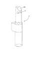
装填装置は、更に、コンテナ、あるいは、バッグセットを受容して、保持するために、1つ以上の実施形態に含まれることができ、遠心分離機システムの外側のバッグセットのよりよい機動性をもたらす際に、コンテナ、あるいは、バッグセットの挿入および/または装填の間の手術者の処理を援助する、あるいは、改善することできる。このような装填装置は、単一の使用でよいか、あるいは、再使用されることができ、したがって、血漿、赤血球および/または血小板(あるいは、軟膜)の以前に完成した成分生成物のそれからの移動、あるいは、取り除き後、新しい分離コンテナおよびバッグセットといっしょに使用するように適用されることができる。 A loading device can further be included in one or more embodiments to receive and hold the container or bag set, and provide better mobility of the bag set outside the centrifuge system. In doing so, it can assist or improve the surgeon's handling during insertion and / or loading of the container or bag set. Such a loading device can be single use or can be reused, and therefore from that of previously completed component products of plasma, red blood cells and / or platelets (or buffy coat) After transfer or removal, it can be adapted for use with a new separation container and bag set.
使用中、その方法および/またはシステムは、スピードなどの遠心分離機回転特性全体の制御、例えば、1つ以上の光学、あるいは、圧力センサおよび制御されたバルブを使用して、それぞれのコンテナ内の、および/または、それぞれのコンテナからのフロー全体の制御を含むことができる。更に、分離された成分生成物、例えば、血漿、血小板(あるいは、軟膜)および/または赤血球のそれらそれぞれの二次的な成分コンテナへの移動は、遠心分離プロセスの後、および/または、遠心分離プロセスの間、すなわち、連続している連侵回転の間であるが、特定の最小分離が達成された後が好ましいいずれかに、遠心分離機システムの内側で行われることが可能である。なお、本明細書中の大部分の実施形態において、あらゆる分離された成分の関連したコンテナへの置き換えは、好ましくは、連続している遠心回転の間に行うようにされることがよく、それに対して、流体層は、その結果、遠心力に施されたままである。ここに一般に説明されるようなプロセスのこのタイプにおいて、血液の1つの分量、あるいは、単位は、通常(必ずしもではないが)、各遠心分離で処理され、それは、遠心分離機における短いプロセス時間が、それからの血液成分の常用製法において極めて好ましいことを意味する。 During use, the method and / or system can control the overall centrifuge rotation characteristics such as speed, eg, using one or more optics, or pressure sensors and controlled valves, in each container. And / or control of the entire flow from the respective container. Furthermore, the transfer of the separated component products, eg plasma, platelets (or buffy coat) and / or erythrocytes to their respective secondary component containers may be after the centrifugation process and / or centrifuged. It can be performed inside the centrifuge system either during the process, i.e. during continuous continuous rotation, but preferably after a certain minimum separation has been achieved. It should be noted that in most embodiments herein, replacement of any separated components into associated containers is preferably done during successive centrifugal rotations, In contrast, the fluid layer thus remains subjected to centrifugal forces. In this type of process as generally described herein, a volume, or unit, of blood is usually (but not necessarily) processed at each centrifugation, which means that the short process time in the centrifuge is , Which means that it is highly preferred in the routine production of blood components therefrom.
本明細書中の1つの別の方法のプロセスの例として、遠心分離機における円形の、環状分離コンテナ、あるいは、バッグ内に配置される全血のチャージは、第1の回転スピード、例えば、3200rpm’sでスピンされることができ、フローが、円形バッグの中、あるいは、外に生じない。その場合、この第1の回転スピードでの遠心分離の周期後、まだその回転はこの第1のスピードで維持されており、選択されたバルブは、システムによって開口されることができ、例えば、血漿などの第1の分離された成分のフローは、連結チューブを通って、遠心分離機の中央コンパートメント内に属する第1の成分コンテナへ円形の環状コンテナから飛び出されることがある。恐らく少しも第1の成分を通らないかなりの量は、分離コンテナから生成物コンテナへ移動される。 As an example of one alternative method process herein, the charge of whole blood placed in a circular, annular separation container or bag in a centrifuge is a first rotational speed, eg, 3200 rpm. 's can be spun and no flow occurs in or out of the circular bag. In that case, after the period of centrifugation at this first rotational speed, the rotation is still maintained at this first speed, and the selected valve can be opened by the system, eg, plasma The first separated component flow, such as, may be ejected from the circular annular container through the connecting tube to the first component container belonging to the central compartment of the centrifuge. A significant amount, possibly not passing through the first component, is transferred from the separation container to the product container.
次に、本発明の実施形態によれば、1つ以上の選択されたバルブは、2つの成分プロセスにおいて、例えば、軟膜、あるいは、赤血球(その中に軟膜を有するか、あるいは、それから濾過される)の第2の成分生成物を圧潰するために連続して、第2のコンテナに供給するように開口、閉鎖されることができ、3つの成分モードにおける場合、その場合、第3の成分が、第3の成分コンテナに移動されることができる。別の方法として、本発明の別の実施形態によれば、第1の成分生成物の圧潰後、第2の、より遅いスピードが、遠心分離機ロータと環状分離バッグとに与えられることができる。このより遅いスピードは、次に、残りの第2および第3の成分生成物の運動量と協働し、軟膜/血小板生成物などの以前に処理された第2の成分を例えば、赤血球層の第3の成分層との界面からはぎ、例えば、血小板の第2の成分を、例えば、血漿の第1の成分の残余部部分に再懸濁する。Coriolis(コリオリ)の力は、第2の成分をはぎ、再懸濁するこのプロセスに(必ずしもではないが)含まれることができる。それにまた、第2の成分、あるいは、血小板再懸濁(そして、たとえあるにしても、懸濁から再処理する、例えば、RBCの第3の成分)の周期後、しかし、更に、連続している回転の間、例えば、血小板の流体懸濁の懸濁された第2の生成物は、第2の生成物、例えば、血小板生成物コンテナへ分離コンテナから圧搾されることができる。この後、例えば、赤血球(RBC)の残りのものである第3の生成物の残りものが、独立した第3の生成物、RBC、生成物コンテナへ移動される、あるいは、圧潰されることができる。最終生成物コンテナは、次に、遠心分離の間、あるいは、後、そのシステムによってバルブ閉鎖される、および/または、シールされることができ、次に、遠心回転の停止時、不連続血漿、血小板およびRBC生成物コンテナは、遠心チャンバの中央部分から独立して取り除かれることができる。これらの最終生成物は、その結果、高い品質の、繰返し可能な、オートメーション化した方法で簡単に製造可能であり、次に、貯蔵、あるいは、直接輸なお/なお入ができ、あるいは、他の使用または処理ができる。 Next, according to an embodiment of the present invention, one or more selected valves are, for example, buffy coat or red blood cell (with or without buffy coat in it) in a two component process ) In order to crush the second component product in succession and can be opened and closed to feed the second container, in which case the third component is , Can be moved to a third component container. Alternatively, according to another embodiment of the present invention, after crushing the first component product, a second, slower speed can be provided to the centrifuge rotor and the annular separation bag. . This slower speed in turn cooperates with the momentum of the remaining second and third component products to allow the previously processed second component, such as the buffy coat / platelet product, to move, for example, in the red blood cell layer. For example, the second component of platelets is resuspended in the remainder of the first component of plasma, for example, from the interface with the three component layers. Coriolis forces can be included (although not necessarily) in this process of stripping and resuspending the second component. In addition, after a cycle of the second component, or platelet resuspension (and, if any, reprocess from suspension, eg, the third component of RBC), but further continuously During the rotation, for example, the suspended second product of the fluid suspension of platelets can be squeezed from the separation container into a second product, eg, a platelet product container. After this, for example, the remainder of the third product, which is the remainder of red blood cells (RBC), can be transferred to an independent third product, RBC, product container, or crushed. . The final product container can then be valve-closed and / or sealed during or after centrifugation by the system, and then when the centrifugal rotation is stopped, discontinuous plasma, Platelet and RBC product containers can be removed independently from the central portion of the centrifuge chamber. These end products can then be easily manufactured in a high quality, repeatable, automated manner and can then be stored or directly transported / still in, or other Can be used or processed.
これらの生成物の白血球減少は、更に、行われることができる。一実施形態において、全血は、全血白血球減少フィルタを使用して、遠心分離の前に白血球が減少されることができる。血小板が乏しい全血の白血球減少フィルタは、血小板生成物における血小板のより大きい回復を可能にするのに使用されることができる。別の方法として、血小板犠牲フィルタが、その場合、例えば、血漿およびRBCsの2つの最終血液成分だけを得る典型的な目標を持って、使用されることが可能である。更に別の方法として、白血球減少濾過作用が、遠心システムからの最終生成物コンテナの取り除き後実質的に従来の方法でか、あるいは、濾過作用が、遠心分離コンテナから、例えば、血小板および/またはRBCs(および/または血漿)のそれぞれの生成物の圧潰の間に遠心システムに生じることがあるかのいずれかで、分離後達成されることができる。このような場合において、1つまたは2つ(またはそれ以上)の白血球減少フィルタが使用されることができる。例えば、単一の血小板およびRBCが乏しいインライン白血球減少フィルタが、分離コンテナから最終生成物コンテナへのフロー流路に配置されることができる。血小板および/またはRBCs(そして、可能な場合、血漿)は、圧潰プロセスの間にこのような単一のフィルタを通して、連続して流通させることができる。あるいは、2つ(または、それ以上)のフィルタが、使用されることができる場合、これらは、それぞれ、分離コンテナからそれぞれの最終生成物コンテナへの独立した出口フロー流路にそれぞれに配置されることができる。このように、フィルタの不連続タイプは、例えば、血小板およびRBCs(および/または血漿)のそれぞれの生成物に使用されることができる。結果として、本発明は、したがって、高い純粋な血漿、白血球および/または血小板、あるいは、軟膜成分、白血球が減少したか、あるいは、そうでないものを提供することができる。 Leukopenia of these products can be further performed. In one embodiment, whole blood can be depleted of white blood cells prior to centrifugation using a whole blood leukocyte reduction filter. A platelet-poor whole blood leucopenia filter can be used to allow greater recovery of platelets in the platelet product. Alternatively, a platelet sacrificial filter can then be used with the typical goal of obtaining only two final blood components, for example plasma and RBCs. As yet another method, the leucopenic filtration is substantially conventional after removal of the final product container from the centrifuge system, or the filtration is performed from the centrifuge container, eg, platelets and / or RBCs. Any of those that may occur in the centrifuge system during crushing of each product (and / or plasma) can be achieved after separation. In such cases, one or two (or more) leukocyte reduction filters can be used. For example, a single platelet and RBC poor in-line leukopenia filter can be placed in the flow path from the separation container to the final product container. Platelets and / or RBCs (and plasma, if possible) can be continuously flowed through such a single filter during the crushing process. Alternatively, if two (or more) filters can be used, they are each placed in a separate outlet flow channel from the separation container to the respective final product container, respectively. be able to. Thus, a discontinuous type of filter can be used, for example, for each product of platelets and RBCs (and / or plasma). As a result, the present invention can thus provide highly pure plasma, leukocytes and / or platelets, or buffy coat components, those with reduced or not leukocytes.
別の方法の更なるセットにおいて、軟膜生成物が、望ましい(最終、あるいは、中間)生成物である場合、軟膜層は、標準のスピンプロセスにおける血漿の後に、RBCsの前に連続して、上述のように取り除かれることができる。あるいは、軟膜は、RBCs/血小板/血漿プロセスのために説明されるほどハードでない(例えば、1500rpm’s、あるいは、2000rpm’s)第1のスピン速度の間に分離されることができ、その結果、軟膜は、単に小さい程度に割当てられることが好ましく、分離ロータの中央セクションへのこれら他の成分の置き換えの間に、隣接した層と最小程度に混合されることがある。軟膜層は、次に、すべての方向(他の生成物が更にあるとき)から均一にロータの中心の方へ向って、径方向に、内方に置き換えられることが可能であり、出口を通して圧潰されることができる(圧潰される必要はない)。別の方法として、軟膜は、分離された血漿および/またはRBCsの圧潰語、リングバッグに属したままであり、次に、軟膜は、リングバッグ自体からその後の分離コンテナの方へプールされることが可能である。このような場合において、RBCsは、例えば、リングバッグの外周のポートか、あるいは、内周から外方へ外周の方へ向って延在するリングバッグに配置される、あるいは、画定される細長いポート構造のいずれかを使用して、遠心プロセスの間に、取り除かれることが好ましい。 In a further set of alternative methods, if the buffy coat product is the desired (final or intermediate) product, the buffy coat is continuously after the plasma in the standard spin process and before the RBCs, as described above. Can be removed. Alternatively, the buffy coat can be separated during a first spin rate that is not as hard as described for RBCs / platelet / plasma processes (eg, 1500 rpm's, or 2000 rpm's) The buffy coat is preferably assigned only to a small extent and may be mixed to a minimum with adjacent layers during the replacement of these other components into the central section of the separating rotor. The buffy coat layer can then be displaced radially inward from all directions (when there is more other product) uniformly towards the center of the rotor and crushed through the outlet. (No need to be crushed). Alternatively, the buffy coat remains in the crush word of the separated plasma and / or RBCs, the ring bag, and then the buffy coat is pooled from the ring bag itself toward the subsequent separation container. Is possible. In such cases, the RBCs are, for example, elongate ports disposed or defined in a ring bag outer peripheral port or in a ring bag extending from the inner periphery toward the outer periphery. Any of the structures are preferably removed during the centrifugation process.
本発明のいくつかの異なる実施形態が、ここでは、添付の図面を参照として、より詳細に説明されており、その図面において、同一要素は、いくつかの図面を通して同一の参照符号で確認される。 Several different embodiments of the present invention will now be described in more detail with reference to the accompanying drawings, in which identical elements are identified with the same reference numerals throughout the several views. .
本発明は、一般に、流体をその分別要素、あるいは、成分要素に分離することに向けられ、全血を、更に血液成分として、あるいは、簡単に成分として知られる、分画への分離に特に有用である。分離は、1つの例として、血液から、これら2つの成分が、一般に、血漿および赤血球(RBCs)である、2つの成分生成物を得るためか、あるいは、別の例として、血液から、典型的な3つの成分分離が、血漿、RBCsおよび軟膜か、あるいは、血小板生成物かのいずれかを含む、3つ(または以上)の成分生成物を得るためのいずれかのために行われることが可能である。なお、血液、特に、全血が、本発明で分離および/または処理される第1の例の流体として使用されるとしても、この原理は、このようなプロセスが、閉鎖された、オートメーション化したシステムで行われることが好まれるときに特に、更に、他の混合流体、あるいは、細胞懸濁液の2つまたは3つまたはそれ以上の分画への分離および/処理に適している。換言すれば、本システムおよび方法は、成分が分離され、次に、システムを開口することなく独立したコンテナに、分離される、あるいは、分離可能であるように望まれるときに特に好ましい。更に、これらのシステムおよび方法は、特に、細胞組成、あるいは、他の身体の、または、生物学的流体に好まれることが多いように、維持された無菌状態が好まれるときに役に立つ。上述の流体は、例えば、それらが、厳密な、あるいは、敏感な診断テストに委ねられことがあるとき、または、患者への更なる注入、あるいは、輸血が予定されているとき、無菌の状態で維持されることが望ましい。 The present invention is generally directed to separating fluid into its fractionation elements or component elements, and is particularly useful for separation of whole blood into fractions, also known as blood components, or simply as components. It is. Separation is typically from blood to obtain a two component product where these two components are generally plasma and red blood cells (RBCs), or from blood as another example. The three component separations can be performed either to obtain three (or more) component products, including either plasma, RBCs and buffy coats, or platelet products. It is. It should be noted that even if blood, in particular whole blood, is used as the fluid of the first example to be separated and / or processed in the present invention, this principle does not allow such processes to be closed and automated. It is further suitable for separation and / or processing into other mixed fluids, or two or more fractions of cell suspension, especially when it is preferred to be performed in the system. In other words, the present systems and methods are particularly preferred when the components are separated and then desired to be separated or separable into separate containers without opening the system. In addition, these systems and methods are particularly useful when maintained aseptic conditions are preferred, as are often preferred for cellular composition or other bodily or biological fluids. The fluids described above are in a sterile state, for example when they are subject to rigorous or sensitive diagnostic testing, or when further infusion or transfusion is scheduled for the patient. It is desirable to be maintained.
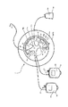
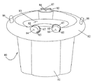
本発明によれば、全体として図1(図1A、図1Bおよび/または図1Cを参照)に確認されるようなシステム/機械18は、好ましくは、遠心力を使用して、1つ以上の分離を行うのに使用されることができる。本発明の理解に必要であるこれらおよび/または類似の遠心力、その生成および/または適用の詳細は、更に、以下で明らかにされ、および/または、両方とも、米国レイクウッドコラルド(Lakewood、Colorado、USA)にある本発明の譲受人であるガンブロ(Gambro、Inc.)、および/またはその子会社のガンブロ BCT(Gambro BCT、Inc.)、から入手できる、コーブ(COBE)(登録商標)2991(商標)、あるいは、ガンブロ(Gambro)(登録商標)オルビサック(Orbisac)(商標)流体分離機械、あるいは、システムなどの類似の、前から存在する機械/システムから理解されることができるような技術から入手できる。
In accordance with the present invention, the system /
本発明のシステム/機械18に使用されることができる様々な別の方法のコンテナのセット10は、図面に示されており、詳細には、例えば、図2ないし図8を参照されたい。図2ないし図8による分離コンテナ11は、バッグセット、あるいは、システム10の一部であり、その第1の実施形態において、分離コンテナ11は、環状および/またはリングタイプである。いくつかの実施形態において、これは、フラットであり、あるいは、それは、多少截頭円錐形分離コンテナ11であり、フレキシブルなプラスチック材料からなり、それは、ある場合に、従来の血液、あるいは、血液成分、または、他の生物学的流体バッグに使用されるようなものと同じタイプか、あるいは、類似のタイプである。分離コンテナは、例えば、上下に配列される2つのプラスチックシートから作られることが可能であり、それは、その場合、1つ以上の環状の、あるいは、ほぼ環状の溶接によって周辺に接合されることが可能である。これらの溶接は、内周部分と外周部分に、少なくとも周辺に形成されることができ、その場合、囲まれた流体分離領域11aと、リングバッグ11によって画定される開口した中央エリア11cに隣接した内側中央セクション11bとを作成する。
Various alternative method container sets 10 that can be used in the system /
図2および図3の相対的に基本で、実質的に概略の実施形態に示されるように、第1の成分収集コンテナ12は、チューブ13によって分離コンテナ11に連結され、第2の成分収集コンテナ14は、同様に、第2のチューブ15によって分離コンテナ11に連結されることができる。2つの上述の連結は、図2および図3に示されるようにリングバッグ11の内周にあり、あるいは、図示されていないが、いずれか、あるいは、2つは、外周に、または、それらの間のいずれか所望の径方向の位置に連結されることが可能である。完成した成分収集コンテナ12、14は、様々な方法のいずれかで形成および/または様々な材料のいずれかから形成されることができる。しかしながら、それらは、いくつかの好ましい実施形態において示されるように、実質的に従来のタイプのフレキシブルなプラスチックシート材料のほぼ矩形のバッグであり、そのプラスチックシート材料は、それぞれのコンテナに貯蔵されるように選択されることができる細胞、あるいは、血液成分生成物のタイプを考慮して選択されることが好ましい。図2の2つの成分(2C)セット、あるいは、キット10において、これら2つの収集バッグ12、14は、単に最終生成物バッグであり、しかしながら、図3の3つの成分(3C)において、第3の生成物収集バッグ24は、更に、第3のチュービングライン、ここでは、ライン25によって、リングバッグ11に連結されることができる。本明細書中に説明される第1の例の全血(WB)分離において、第1の収集バッグ12は、血漿を受容するように構成され、第2の収集バッグ14は、RBCsを受容するように構成され、第3の収集バッグ24は、3Cセットにおいて、好ましくは、血小板を受容するように構成されることができる。なお、第3の収集バッグ24は、別の方法として、軟膜を受容するように配置されることができ、とはいっても、恐らく最も一般に、あるいは、好ましくは、これは、血小板生成物である。これら、あるいは、類似の場合のいずれかにおいて、収集バッグ24は、したがって、例えば、図6に示されるように、より小さいバグである。
As shown in the relatively basic and substantially schematic embodiment of FIGS. 2 and 3, the first
全血の分離および血液成分生成物の製法において、バッグは、最初は、全く空であるか、あるいは、1つ以上の二次的バッグ、例えば、第2の成分コンテナ14には、最初は、その中に配置される成分、例えば、赤血球のために特定量の添加剤、あるいは、貯蔵流体、または、液体16が充填されることができる。このような流体の例は、SAG溶液、あるいは、SAG−M溶液(SAG−Mは、更に、マンニトールを含むSAG溶液である)として知られる生理的食塩水アデニングルコース溶液を含むことができ、あるいは、とりわけ、AS−1、AS−3、あるいは、AS−5を含む他の別の添加剤溶液を含むことができる。添加剤溶液16がバッグ14内に事前配置されている図2および図3を参照されたい。別の方法として、貯蔵、あるいは、添加剤溶液16は、任意の独立したバッグ内に事前配置されることができる、例えば、バッグ14から導く添加剤溶液チューブ27と連結チューブ28(破線で示される)とを経由してバッグ14に連結される、あるいは、バッグ14と連結可能な、図2の衛生のようなバッグ26(破線で示される)を参照のこと。図2のライン28に概略的に表わされる任意の無菌の障壁、あるいは、フィルタ29は、更に、スパイク連結などが使用される場合に含まれることができる。添加、あるいは、貯蔵の溶液16は、次に、ライン27、28を経由して、このような衛星コンテナ26からコンテナ14へ通過されることができる(あるいは、ある別の方法では、血液成分生成物はバッグ14から溶液バッグ26へ通過される)。いくつかの実施形態において、溶液バッグ26は、すなわち、セット10の製造プロセスの間に、バッグ14へ事前連結されることができる、あるいは、別の方法として、添加剤溶液バッグ26は、無菌のドッキング、あるいは、スパイク連結(など)によって後で連結される、あるいは、ドッキングされることができ、その結果、セット10の部分内に、あるいは、セット10の部分として以前に貯蔵されることができないが、その代わりに、血液成分分離/処理の前、あるいは、後に異なる時間に追加される。なお、図3に概略的に、より具体的に示されているのは、添加剤溶液チューブ27がないRBCバッグであるが、むしろ、述べられるように、その中に事前配置される添加剤溶液16は、セット10の製造の間でよく、あるいは、そうでない場合、使用前でさえ後で追加されることができる。成分コンテナ14は、このような場合に、次に、例えば、いわゆる、脆弱部、あるいは、破壊ピン17、あるいは、剥離可能な、または、圧力破壊可能なシール(本明細書中には図示されていないが、以下の説明を参照)などの他のシール手段によって、一時的にシールされることができ、その使用が望まれるまで、すなわち、遠心分離機に充填され、RBCsなどの成分生成物を受容する準備ができるまで、その溶液をその中にシールさせる。血小板バッグ24(図3を参照)について、貯蔵、あるいは、添加剤溶液(血小板添加剤溶液、または、PAS(例えば、T−Sol))(図示せず)は、同様に、それに後で追加される成分生成物の利益のために、バッグ24に事前配置されることができる、あるいは、バッグ24に追加されるように構成されることができる。
In the whole blood separation and blood component product manufacturing process, the bag is initially completely empty, or one or more secondary bags, such as the
具体的に説明される実施形態などの多数の実施形態において、分離コンテナ11には、無菌ドッキング(あるいは、そうでないもの)によって、独立したWBバッグ20などの全血(略語、WBによって本明細書中に時々示される)の源へ連結されることができる連結チューブ19が設けられることができる、図2の概略の無菌ドック描写部23を参照されたい。これに反して、図3は、ドッキングがないが、その代わりに、チュービングライン19によって、WBバッグ20の分離バッグ11への別の方法の事前連結を示している。WBバッグ20が使用されるいずれの場合、それは、多くの実施形態において、遠心分離の前に、取り除かれる(必ずしもではないが)。この取り除きオプションは、エネルギー波、例えば、メカニズム/プロセスをシールおよび切断する無線周波数を表わすことが可能な、1つまたは複数の分断矢印23aによって、図3に概略的に示される。任意の白血球減少フィルタ70は、更に、入口ライン19(これらは、以下に更に説明される)に示される。バッグ20は、いずれの場合にも、供血者(図示せず)への連結のために、チュービングライン21によって、カニューレ/針22に連結されることができる。供血者からバッグ20に収集される全血は、次に、チュービングライン19を経由して、バッグ20から分離コンテナ11に通過されることができる。そうでない場合、図2および図3に示される(破線で)ように、中間のバッグ20は、任意にバイパスが付けられ、あるいは、機能的に、および/または、構造的に、削除されることができ、分離コンテナ11は、その代わりに、より直接に、血液入口チューブ19と連結可能な、あるいは、血液入口チューブ19に事前連結される、あるいは、血液入口チューブ19の部分として、離脱チュービングライン21aを経由して設けられる針、あるいは、離脱カニューレ22aに連結されることができる。血液は、したがって、直接供血者(図示せず)から分離コンテナ11に供与されることが可能である。なお、バッグ20(あるいは、バッグ20が使用されない場合、分離コンテナ11)は、抗凝固血薬チャージ(CPD、あるいは、CP2Dなどの)(クエン酸リン酸デキストロース、あるいは、クエン酸リン酸2−デキストロース)、または、ACD、あるいは、ACDA(クエン酸デキストロース溶液)を有することが可能であり、あるいは、そうでない場合、事前配置される、あるいは、そうでない場合、その中に供給される、あるいは、その中に血液収集の前に(あるいは、後に)それに追加されることが可能である。
In many embodiments, such as those specifically described, the
様々な異なるコンテナには、更に、リングバッグ11内に、ポートまたは連結30、31、32および/または33などの充填および/または離脱ポート、あるいは、連結、あるいは、コネクタが設けられることができる(例えば、図2ないし図6および図7Bを参照)。これらのポートは、血液、あるいは、血液成分コンテナ、あるいは、バッグに、あるいは、上に頻繁に使用されるものと同じタイプでよく、それを通る流体連絡をもたらす。分離コンテナ11には、分離コンテナ11のそれぞれの内周37と外周38とを画定するように配置される1つ以上の溶接部分35、36が設けられることができる。このように、リングバッグ11は、内側溶接35および/または内周37によって実質的に画定される内側開口エリア11cを有することが可能であり、そのことは、更に以下で探求されるような利点をもたらすことができる。内側溶接35は、ポート30、31、32、それを通って画定される任意の付加的なポート33を有することができる(特に、図5、図6および図7Bを参照)。上述のポート30−33は、不連続ポート構造(独立して図示せず)でよく、あるいは、もっと簡単に、それぞれのチュービングライン13、15、19および/または25へのコンテナ11の内側と適切な流体連絡への溶接連結でよい。ポート32は、入口ライン19を分離バッグ11に連結するのに使用されることができる。したがって、図2の2つの成分の場合では、分離コンテナ11をそれぞれの第1の成分コンテナ12および第2の成分コンテナ14に連結するチューブ13、15(とりわけ、更に、図3、図4A、図5および図6を参照)は、その結果、それぞれのポート30、31を経由して内側溶接35を通過するように配置されることができる。成分コンテナ12、14には、同様に、それらの外側エッジに溶接部分、あるいは、継目34が設けられ、それを通るチューブ13、15(および/またはポート構造(独立して示されない、あるいは、明らかにされていない))の通過を可能にする。チューブ13、15は、他の従来の(あるいは、慣例に従わない)生物学的流体コンテナ内、および、を通る上述の連結と異ならない溶接(あるいは、貫通ポート)によって、継目34に、継目34を通して連結される。図3の第3の成分コンテナ24は、任意に、付加的に、チュービングライン25を経由して、リングバッグ11へのそれぞれのポート33を通って同じように連結される、図3、図4A、図5および図6を参照されたい。第3のバッグは、更に、その中への連絡、例えば、それを通るチュービングライン25の連結をもたらすために、その中に、および/または、それを通って位置決めされる1つ以上のチューブ(あるいは、ポート)がそれらの周りに配置される溶接部分、あるいは、継目34を有する。述べられるように、第3のバッグ24は、軟膜、あるいは、より多いと思われる、血小板生成物を受容するように配置されることができ、その場合、バッグ24は、例えば、図6に示されるようにより小さいバッグであることが多い。
Various different containers can further be provided in the
サブパートの図4Aおよび図4Bを含む図4において、リングバッグ11のより詳細で、更に、実質的に概略図が示されている。図4Aおよび図4Bの両方において、リングバッグ11は、そのパーツ、囲まれた流体分離エリア11a、内周エリア11bおよび開口中央エリア11cを有して示されている。更に、2つの図面に示されているのは、その結合ポート32を有する入口ライン19、それぞれの出口ライン13、15、25である。しかしながら、それぞれのポート/連結30、31、33のそれぞれは、図4Aだけにおいて、バッグ11に連結されて示されている。図4Bにおいて、別の方法のポート手段、あるいは、構造が示され、単一のポート、あるいは、チュービング連結30は、ポート30に連結されるチュービングライン13から広がる対応する分岐ポート、あるいは、コネクタ31a、33aでバッグ11に連結されて配置されている。分岐ポート31aは、出口ライン15に連結し、分岐ポート33aは、出口ライン25に連結する。なお、以下でより詳細に説明されるように、出口ラインは、フロー制御バルブサポート部材41に配置されるように示される。更に、オンライン濾過のために、別の方法の白血球減少フィルタ74は、図4Bに見せかけで示され、これは、更に、以下で更に説明される。
In FIG. 4, including the subparts FIG. 4A and FIG. 4B, a more detailed and substantially schematic view of the
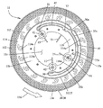
図5に示される別の方法の実施形態において、分離コンテナ11は、拡大概略図で示され、環状流体チャンバ11aは、内側溶接35/内周37と外側溶接36/外周38との間に画定されて示されている。なお、この図5の実施形態において、環状流体チャンバ11aは、分離コンテナ11の360度周り流体連絡に開口していない。これは、図2ないし図4および図6に概略的に表わされるような完全な開口フローエリアとは反対である。図5のこの別の方法の実施形態において、この別の方法の閉鎖した連絡エリアは、全体として、参照符号11dで確認される。いくつかの実施形態(図5において、本明細書中に示されるものと同じ)において、このクロージャは、それぞれの材料の層の溶接によって、あるいは、材料の相互の層の重ね合わせ、そうでない場合、オバーラッピングによって形成されることができる。
In another method embodiment shown in FIG. 5, the
初期のフラットなバッグからの材料のオーバーラッピングは、本明細書中の特定の実施形態に望まれるように、バッグ11の円錐形状を生成するのに使用されることが可能である、例えば、図7Bおよび図8ないし図14を参照されたい。コンテナの円錐形状は、多量の血液における多量の赤血球の沈降間隔、すなわち、径方向移動間隔を減少するのに有益である。液体が移動することができる径方向範囲のこの限定は、比較的より迅速な分離と、比較的フラットなロータに経験される間隔および/または界面との間の比較的小さな界面とを結果として生ずることができる。
Overlapping material from an initial flat bag can be used to generate the conical shape of the
更に、図5(そして、図6を参照)のこの別の方法の実施形態に画定されているのは、対向する外側溶接境界35aと内側溶接境界35bとによって画定される半円形の内側フロー分配チャンネル45である。一般に、分配チャンネルは、分離コンテナ11が遠心分離機によってスピンされるとき、チャンネルに含有されるあらゆる流体が、分配チャンネルを出て、環状流体チャンバ11aへ流入するように形成される。チャンバ11aから/へのこの分配チャンネル45へのアクセスは、開口、あるいは、湾状エリア30aを経由してもたらされることができる。ポート32を通る入口フローおよび/またはポート30、31および/または33を通る出口フローは、次に、分配チャンネル45と/へ、分配チャンネル45を通って流体チャンバ11aへ、および/または、流体チャンバ11aから連絡することができる。リングバッグ11(11dでのように閉鎖、あるいは、図2ないし図4および図6でのように開口)の様々なチャンバおよびチャンネルにおけるフローの特性は、以下で更に説明される。なお、湾状エリア30aは、内側溶接35/内周37の径方向範囲から減少する、段々に減少する径方向入口湾状エリアを有することができる。
Furthermore, defined in this alternative method embodiment of FIG. 5 (and see FIG. 6) is a semi-circular inner flow distribution defined by opposing outer and
例えば、図5および図6に特に具体的に示されるような多数の実施形態において、分離コンテナ11には、更に、中央セクション11b内に、あるいは、中央セクション11bに隣接して、および/または、内側開口エリア11cに隣接して、コンテナを貫通する多数の穴、あるいは、開口39が形成されることができる。述べられているように、コンテナ11の対向する頂部壁および底部壁(プラスチックシート)は、いくつかの部分において、互いに溶接されることが好ましい、例えば、開口内側エリア、あるいは、スペース11c周りの内側エリア11bの溶接エリア35(およびエリア35a、35b)を参照、穴39は、この(あるいは、これらの)エリア35(および/または35a、あるいは、35b)を通って、あるいは、隣接して形成されることができる。明快に示されていないが、内側周辺の、あるいは、近くの小さい部分、あるいは、内側エリア11bの大部分、または、全体だけが、溶接された状態である。穴39は、その場合、場合により、溶接プラスチックで形成されるか、溶接されなくてもよい。これらの穴39は、その場合、更に、遠心分離機ロータ40(図7))に/上に配置される1つ以上のロータサポート部材41(図3、図4および図7ないし図17、特に、図7、図10、図16および図17を参照)と協働するように構成されることができる。ロータサポート部材41は、穴39に、穴39を通して挿入されるように構成されることができ、それによって、その上に、および/または、その周りに配置される溶接エリア35の部分および/または内側エリア11bの対応する部分を有し、そのために、ロータサポート部材41は、その上にコンテナ11を受容して、それによって、支持することができる。図5および図6に示されるように、それぞれのチュービングライン13、15および/または25の部分は、それぞれの開口39内に配置され、および/または、それぞれの開口30内に、および/または、横切って固定されることが好ましく、そのために、これらのそれぞれのチュービングラインセグメントは、以下で更に説明されるように、それぞれのサポート部材41に対して位置決めされることが望ましい。更に別の方法の付加的なサポート開口39aは、更に、図5に示される。これらの開口39aは、ロータ40に操作可能な状態に分離バッグ11を維持する際の更なるサポートをもたらすことができる(この更なる1つまたは複数の説明は以下で述べられる)。
For example, in a number of embodiments, as specifically illustrated in FIGS. 5 and 6, the
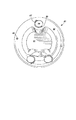
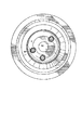
それぞれの装填した、装填されないロータターンテーブル40は、特に、図7ないし図15に示されている。一般に、図7ないし図10は、その中に/その上に配置される、あるいは、装填される分離セット10を有するターンテーブル40の図であり、図11ないし図15は、空の、あるいは、装填されてないロータターンテーブル40の実施形態を具体的に示している。ここでは、より詳細に説明するために、装填されていないロータターンテーブル40が、図7Aに示され、対応する装填したロータターンテーブル40が、図7Bに示されている。図7Aの空のロータターンテーブル40は、概略的に、円錐形に下に傾斜する分離エリア50(内側部分から外側エッジの方へ向ってとられる)を示す。円錐形に下に傾斜するロータターンテーブルの実施形態が、更に、図7Bおよび図8ないし図14に示されている。平面のロータターンテーブルは、図15に示され、円錐形に上に傾斜するロータの場合は、図面に示されていない。図7、特に、図7Aに戻ると、内側、あるいは、中央開口コンパートメント52は、更に、3つの隣接したサポート部材41を有して示されている。サポート部材は、特に、開口中央コンパートメント52内に部分的に(示されるように)、あるいは、開口中央コンパートメントから外に完全に位置決めされることができる。サポート部材41は、更に、それぞれ、その中に配置されるバルブ部材42を有することができる。図7Bの装填したロータターンテーブルの場合は、その上に装填されるバッグおよびチュービングセット10を含む。特に、分離コンテナ11は、分離エリア、あるいは、スペース50の上に/内に装填されて示されている。最終生成物コンテナ12、14(および/または24(本明細書中に、この角をなす配置で示されていないが))は、ロータ40の中央エリア、あるいは、コンパートメント52内に操作可能な状態で装填されている。
Each loaded and unloaded
分離セット10のそれぞれのバッグを連結するチューブは、その場合、遠心分離機ロータ装置40の保持マウント、あるいは、サポート部材41のそれぞれの中央部分に取り付けられることができる1つ以上のピンチバルブ42(図7Aおよび図7B、以下で説明される図16および図17を参照)によって係合可能であることが好ましい。そのピンチバルブ42(図16)は、それぞれ、ふたつの逆に配置されたクランプ要素43、44(図16および図17を参照、特に、図17Cを参照)を含むことができ、それらは、クランプ要素43、44が、互いに隣接して結び合わされることができるように機能的に結合される(図示せず)、あるいは、別の方法として、それらの間に特定のスペース46を画定するように開口される(図17Bおよび図17C)。クランプは、示されるようにほぼフラットでよく、あるいは、その中にそれぞれの丸いチュービングラインの受容を容易にするようにわずかにカップ状にされることができる。クランプ要素は、クランプ装置42(クランプ要素43、44を有する)が、コンテナ11のそれぞれの穴39を延通し、チューブ13、15および/または25が、それぞれのバルブスペース46に通される、および/または、そうでない場合、それぞれのバルブスペース46に配置されるとき(とりわけ、図7Bにおけるように)、それぞれのチュービングライン13、あるいは、15および/または25(あるいは、任意に図示されていないが、可能な場合、19でさえ)のいずれかの側から互いに機能的に作用する。なお、図16A、図16B、図16C(そして、一般に、図7Bおよび図7Aを参照)に示されるように、傾斜した頂部面41aは、例えば、チュービングライン13のライン部分13aのバルブ42の適切な位置決めへのチュービングラインの分配を容易にするために装填プロセスの間に使用される。図16A、図6B、最後に、図16Cのシーケンスに示されるように、分離コンテナ11は、コンテナ11の1つ以上の対応する開口39と整列される1つ以上のサポート部材41の方に下方へもたらされることが可能である。分離コンテナ11に固定して連結され、示されるように開口39を横切って配置される、本明細書中に描写される部分13aなどのチュービング部分は、次に、サポート部材41の面41aと接触する。その面41aが、本明細書中に示されるように傾斜される場合、その場合、分離コンテナ11の連続している下方への動きは、チュービング部分13aの下方への角をなす動きによって容易にされる。更なる援助は、チュービングラインが、弾力的であり、その結果、示されるように幾分引き伸ばされることができ、次に、図16Cに示されるように、その通常の、ほぼ、直線状態にはね返り、そこで、それは、バルブ42として位置することになる。図8ないし図15に示されるのと同じく減少した幅、部分的にフラットで/部分的に角をなした面を含む、他の形状の面41aも、そのうえ、この種類のプロセスに役立つことができる。
The tubes connecting the respective bags of the separation set 10 are then one or more pinch valves 42 (which can be attached to the holding mount of the
1つまたは複数のバルブ42のクランプスペース46は、溝形状表面48(図11、図16、図17)および/またはロータのターンテーブル40の中心の方へ向う開口内側コンパートメント52の方へ内方へ向うバルブスペース46を開口するように画定されることが可能な別の方法の開口の口状エリア47(図7Aおよび図7Bの図に多少示されるように)を有することができ、あるいは、その口状部47およびスペース46は、コンテナ11の外周38の方へ面して外方へ開口することが可能であり(図示せず)、あるいは、それらは、それに直交して(図5および図6の穴39に位置決めされるようなチュービングラインと協働する場合のように)、あるいは、それに対してあらゆる他の角度で(とりわけ、例えば、図9ないし図12に示されるように)開口することが可能である。それぞれのチューブ13、15および/または25(および/または19)は、次に、以下で更に詳細に説明されるように、取り付けプロセスと連絡して1つ以上のそれぞれのバルブ開口46(図7ないし図10、図16および図17を参照)に挿入されることができる。クランプ口状部47は、三角形に(図示せず)、あるいは、矩形に(示されているように)形成されることができる、あるいは、開口に(図示せず)、48の後に画定されるわずかに曲線をなすエッジ部分を有することができ、それにより、クランプ要素間に形成される、本質的に、V−形状、U−形状、あるいは、S−形状、または、他の形状の溝開口46を結果として生ずることができる。図17、特に、図17Cに示されるように、スペース46を横切る要素43の方へ向う要素44の動きは、要素44が接触することが可能なそれへの、あるいは、それに対するシャフト49の動きによって達成されることが可能である。別のロッド49aは、更に、シャフト49に接触し、シャフト49を移動するのに使用されることができる。
The clamping
いくつかの実施形態において、クランプ42は、更に、その中に配置されるあらゆるプラスチックチュービングラインを選択的に溶接および/または切断するために、例えば、無線周波数(RF)などのエネルギー波、溶接および/または切断性能を有することができる。このように、一般の使用において、チュービングラインは、選択される処置により、クランプで締めつけられることが可能か、あるいは、クランプで締めつけて、溶接される、あるいは、クランプで締めつけられて、溶接されて、切断されることが可能であるかである。エネルギー波は、図17Cの要素44などの1つのクランプ要素から受容要素43の方へ向って放射させられる。パワーおよび/またはエネルギーは、シャフト49(使用される場合、および/またはロッド49aなど)によって、および/または、シャフト49を介して伝えられることができる。
In some embodiments, the
上記に紹介されるように、図7ないし図10は、遠心分離機のロータ40に/上に配置される分離セット10を有するロータターンテーブル40の図を示し、図11ないし図15は、空のロータ40の実施形態を具体的に示している。ロータ40は、分離スペース50が環状分離コンパートメント51と中央コンパートメント52とを備えるタイプであり、それらは、ロータの回転シャフト53(図11および図15)と同軸に配置され、バルブからなるゾーンを通して互いに連絡する。分離スペースには、任意の着脱自在のロータカバー55(図1Cおよび図13、図13Aおよび図13Bを参照)がカバーされている。上記に紹介されるように、ロータのターンテーブル40の中心には、1つ以上の二次的な完成した成分コンテナの12(血漿コンテナ)と、14(RBCコンテナ)と、任意に更に、24(血小板、あるいは、軟膜コンテナ)とが置かれることができるスペース52がある。図2に示される2つの成分実施形態、あるいは、図3の3つの成分実施形態に適応する際には、ほぼ円筒形スペース52は、したがって中央コンパートメント52を画定することができるロータシャフト53に、あるいは、に隣接して配置されることができ、前にこのスペースに置かれることが可能な第1の成分コンテナ12および/または第2の成分コンテナ14および/または第3の成分コンテナ24を受容するように構成され、その結果、遠心分離の間有用である。なお、本明細書中に主に説明されるものなどの大部分の実施形態において、中央コンパートメント52は、実質的に、シャフト53に固定して連結され、その結果、コンパートメント52は、コンテナ12、14および/または24を含むその中身のいずれかを行うように、遠心分離の間それとともに回転する。
As introduced above, FIGS. 7-10 show views of a
ロータカバー55は、界面を視角によって検査する人による技術者によって(おそらく、ストロボからフラッシュされるか、別の方法によるストロボおよび/またはカメラの助けで)、あるいは、周囲のロータターンテーブル40に、および/または、ターンテーブルカバー55に、および/または、別の方法として、比較的固定した静止した機械の蓋56(図1Aないし図1C)に取り付けられることができる1つ以上のセンサ58、59(図1Cに概略的に示される2つ)によって、分離した動きをモニタすることを可能にする透明な材料から作られることが好ましい。フォトセルでよいセンサ58、59は、分離コンテナ内の、あるいは、それに連結されるライン内の流体コンポーメントの少なくとも1つの特性(例えば、色、濁度など)を検出することができる。それらのセンサは、分離コンテナ11からそれぞれの収集ライン13、15、25への流体成分の流路に面するように、ターンテーブル40、あるいは、ターンテーブルの蓋55に取り付けられる。なお、図5に表わされる分離コンテナ11を受容するように構成される分離機械において、1つのセンサのみが必要とされ、分配チャンネル45と環状チャンバ11aとの間の湾状エリア30aに面している。なお、その配置により、とりわけ、フォトセル58、59は、特定の流体フローをモニタするために、透明の材料を有して、あるいは、透明の材料を有さずに使用されることができる。他のタイプの他のセンサ(図示せず)は、更に、使用され、ハウジングおよび/またはターンテーブル40に配置されることが可能である。フォトセル、あるいは、他のセンサは、1つのスイッチ、あるいは、複数のスイッチを作動させる、あるいは、相応じて機械18またはハウジングに取り付けられる制御ユニット60(符号60で示される制御パネルによって図1に概略的に表わされる)と連絡する、および/または、制御ユニット60に送信されることが可能な信号を生成することができる。説明されるようなそれぞれの1つまたは複数のチューブバルブ42および/またはシステム全体の他の特色は、したがって、制御ユニット60によって制御されることができる。制御ユニット60は、1つの簡単な実施形態において、チューブバルブ42をその閉鎖した位置にスイッチする電磁石を含むことができる。他の実施形態において、制御ユニットは、1つ以上の電子回路コントロール、プロセッサおよび/またはマイクロプロセッサを含むことができる。それは、特に、様々な分離プロトコル(分離される混合流体の性質、収集される流体成分の数および性質、スピンスピード、分離前のスピンタイムなど)が格納されることができる分離機械のメモリに連結されることが可能である。制御ユニット60は、したがって、それが受信するデータを処理するだけでなく、プログラムされた、あるいは、プログラム可能な命令により制御信号を発するだけでなく、コンピュータの性質からなり、それは、更に、データを記録し、他のコンピュータ、あるいは、コンピュータタイプの装置と連絡することができる。
The
更に、ロータターンテーブル40は、分離コンテナ11を圧搾するための、すなわち、分離コンパートメント51から中央コンパートメント52のその関連したコンテナ、あるいは、バッグ12、14、あるいは、24に分離した分画、あるいは、成分生成物を配置、あるいは、圧潰するために、回転の間分離コンパートメントの容積を減少するための手段を備えることが好ましい。図2および図3に具体的に説明される2/3成分の実施形態のそれぞれにおいて、ポンプステーション62は、ロータシャフト53の、図14および図15に示されるようなダクト61を通って、ロータターンテーブル40に固定されるフレキシブルなダイヤフラム65によって規定されている環状の膨張可能な液圧チャンバ63にポンプで送ることによって、分離コンパートメントの容積を減少するのに使用される。液圧流体は、中央チャンバ52の側方周りに、あるいは、沿って、遠心分離機のモータ64を貫通する連続的なダクト61を通って、それゆえ、液圧チャンバ63へポンプで送られることができる。圧力センサ99は、膨張可能なチャンバ63にフィードされる液圧回路に連結される。圧力センサ99からの圧力情報は、制御ユニット60にもたらされる。制御ユニット60は、検出される圧力が、空である分離コンテナ11に対応する高圧しきい値に達したとき、遠心分離機およびポンプステーション62を停止するために、圧力情報を使用するようにプログラムされることができる。制御ユニット60は、更に、圧力センサ99によって感知される圧力と分離機械のメモリに格納される予め定められた圧力しきい値との間の比較の機能として、ポンプステーション62を制御することができ、様々な流体成分が、分離コンテナ11から収集コンテナ12、14、24へ移動されるフロー速度に適応する。これは、赤血球のような脆弱性の流体成分にとって特に重要である。図14は、円錐形の下に傾斜するロータターンテーブル40の実施形態において、これを概略的に示し、分離チャンバ51/液圧チャンバ63には、ダイヤフラム65の下に、液圧流体がほぼ半分充填されて示されている。図15Aないし図15Cの別の実施形態において、ほぼ平面ロータターンテーブル40の実施形態が示され、図15Aにおいて、分離チャンバ51/液圧チャンバ63には、ほぼ半分充填され(ここではフラットであるが、図14に示されているのとは異ならない)、図15Bおよび図15Cは、一般に、最初に、圧潰作動の開始での、次に、そのプロセスの終りでのそれぞれの状態であるように、それぞれに、ダイヤフラム65の下に、極めて部分的に充填された分離チャンバ51/液圧チャンバ63だけを、次に、ほとんど完全に充填された分離チャンバ51/液圧チャンバ63を示している。
Furthermore, the
更に、図14および図15Aに概略的に示されるように、1つ以上のスリップリング装置66は、定置の電源装置(図示せず)から回転ロータ40に、より具体的には、遠心回転の間の作動のためのパワーを必要とする回転ロータ40への要素に連絡するために、遠心分離機モータ64に、および/または、周りに配置されることができる。これらの間に、ロータサポート部材41に配置されるクランプバルブ装置42がある。パワーは、単なるクランプ/バルブ機能のために、回転の間これらのバルブ42に供給されることができる、あるいは、更に、所望の場合、その中に配置されるあらゆるプラスチックのチュービングをシールおよび/または切断するために、例えば、無線周波数(RF)などのエネルギー波を供給する。更に、パワーは、回転ロータ40に、および/または、上に、配置される1つ以上のフォトセル58、59、あるいは、あらゆる他のセンサ(図示せず)に供給されることができる。
Further, as schematically shown in FIGS. 14 and 15A, one or more
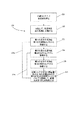
本発明による様々な分離システム(機械18およびバッグセット10)の機能およびプロセスは、最初に、一般に、成分要素を有する混合血液、あるいは、全血に適用される、次に、全血供給/収集を成分収集生成物へ分離するこのようなシステムの使用に特に注意を払うように、ここでは説明されている。図18を一般に参照すると、基本プロセスが、最初に、詳細に説明され、別の方法が、以下に説明されている。
The functions and processes of the various separation systems (
図18(図18Aおよび図18Bの両方)に示される一般プロセス120の第1の工程121は、分離可能な部分の混成物である全流体は、分離コンテナ/バッグ11に供給される。次に、第2の一般工程122において、全流体はスピンされ、成分要素は、それによって、分離される。次に、ボックス123に示されるように、第1の成分生成物は、分離コンテナ11から第1の生成物コンテナ12に移動、あるいは、圧潰される。第2の成分生成物は、更に、分離コンテナ11からその第2の生成物コンテナ14に移動、あるいは、圧潰される。これは、プロセス図120のボックス124によって描写されている。最後に、第1および/または第2の成分コンテナ12、14は、入口、例えば、それへのチュービングラインをバルブで調節、シールおよび/または切断することによって、閉鎖される。これは、ボックス125によって/で描写されている。なお、一般概念として、第3、第4および第5の工程123、124、125は、独立して、および/または、遠心分離の停止および第2の工程122の分離後生じることができ、あるいは、ここでより一般的に、工程122の回転遠心分離122は、他の工程123、124および/または125およびあらゆる別の方法および/またはそれへの中間工程の実行を通して続ける。したがって、回転/遠心分離および分離工程122は、工程123、124および/または125およびそれへのあらゆる手段および/または別の方法の完了後のみ通常中止することがここでは最も多い。第2の工程122の停止は、次に、通常のプロセスの終りを構成する(なお、不充填および/または他の管理タイプの処理プロセス、マーキング、標識付け、貯蔵、それにもかかわらず、事後処理が行われる場合、同じ事後の遠心分離プロセス工程)。なお、別の方法の、任意のプロセスライン123aは、更に、バルブでの調節、シールおよび/または切断工程125は、第4の工程124の前に、あるいは、間に、いずれの場合にも、第2の生成物コンテナのためのバルブでの調節、シールおよび/または切断工程の前に、から独立して、第1の成分コンテナに対して行われることができるという別の方法を強調するために、図18Aに示されている(破線で)。
In the
更に、図18Aに任意に、破線で示されるのは、分離コンテナから第3の生成物コンテナへの第3の生成物の動き、あるいは、圧潰のための中間工程126である。なお、別の方方法の任意のプロセスライン124aは、更に、バルブでの調節、シールおよび/または切断工程125が、中間の任意の工程126の前に、あるいは、間に、いずれの場合にも、第3の生成物コンテナのためのバルブでの調節、シールおよび/または切断工程の前に、から独立して、第2の成分コンテナに対して行われることができるという別の方法を強調するために、図18Aに示されている(破線で)。
Further, optionally in FIG. 18A, indicated by a dashed line is the movement of the third product from the separation container to the third product container, or an
別の方法の工程系統図18Bが、更に、示され、プロセス全体128が、更に、2つの成分(2C)プロセスと3つの成分(3C)プロセスとの間を選択するための決定ボックス129を含んで示されている。2Cプロセスが選択される場合、その場合、プロセスはボックス126を回避して、工程125に直ちに進む。一対の破線の描写123a、124aは、上記に説明される目的のために示されている。更に、任意の決定ボックス128aが、手順の開始に、あるいは、近くで一般に起こる(なお、別の方法は、決定、あるいは、少なくともその実行は、プロセスの後に起こることがある)オペレータによる選択の任意性を示すために、プロセスフローの初期に破線で示されている。ボックス128aと129との間の破線連結128bは、通常の場合であるように、工程129でプロセスフローに使用する選択データの起こり得る移動を表わすために示されている。第1の工程、ここでは、121aは、セット10のロータ40への物理的装填および/またはその中の全血などの混合流体の装填を含むことができるセットの装填を示している。以上および他の別の方法は、以下で更に詳細に説明される。
Another method flow diagram 18B is further shown and the
この一般プロセスへのいくつかの重要な別の方法は、限定されるものではないが、以下のものである。第1の工程121において、全流体は、分離コンテナ11に供給されるしかしながら、これは、間接的に独立した初期の収集バッグ20に、先ず供給および/または収集される全血などの流体を含むことができる、あるいは、むしろ、供血者から分離コンテナ11に直接に供給されることができる。これらの別の方法は、例示として、図2および図3に関して上記に説明され、独立した連結していない、あるいは、別の方法として、事前連結された全血収集バッグ20は、初期の全血供給/収集に使用されることができる(針22および収集チューブ21を使用して)。このようなバッグ20は、前に独立して、連結していない場合、収集後、次に、分離コンテナ11に連結されることができる。血液は、次に、血液入口チューブ19を通って分離バッグ11にバッグ20から引き込まれる。そうでない場合、血液は、別の方法の収集ライン21aおよび針22aを通って、直接供血者から分離コンテナ11へ運ばれる。一般に、血液のほぼ450mlが、全血供給の間に収集される。述べられるように、抗凝固血薬が、同時に供給されることができる、あるいは、バッグ20および/または分離コンテナ11にあらかじめ供給されることがある。供給/収集の間、バッグ20、あるいは、分離セット10全体(バッグ20に事前連結される場合、あるいは、収集が、丸いバッグ11に直接の場合)は、血液を混合状態に維持するために、技術上周知のような揺れる血液揺りかご体に置かれることができる。したがって、この第1の工程121は、その一部分として、および/または、それへの前篇として、供給/収集および/または移動、あるいは、全流体の分離コンテナ11への供給を含むことができる。
Some important alternatives to this general process include, but are not limited to: In the
次に、この第1の工程121の完了後、あるいは、可能性として、更に、一部として、独立した全血収集バッグ20が、使用される場合、任意にではあるが、好ましくは、断絶される、あるいは、そうでない場合、セット10から分断される(図3の分断部23aを参照)。セット10から分離されない場合、その場合、このバッグ20は、セット10の残りとともにロータ40内に装填されることになる。
Next, after completion of this
次の考慮すべき事柄は、これらの初期の工程が機械18とともに行われる時期および方法である。分離コンテナ11を充填することは、述べられるように、供血者から直接生ずることができる、あるいは、分離コンテナ20から充填されることができる、が、これらの充填プロセスが行われる方法は、まだ十分に説明されていない。別の方法の1つのセットにおいて、重力排出(供血者か、あるいは、独立したバッグ20かのいずれかからの)は、バッグ11を充填するのに使用されることができる。このような場合、コンテナ11は、通常、流体の源よりも低い位置に配置される必要がある(供血者、あるいは、不連続バッグ20であろうと)。したがって、コンテナ11は、通常、これらの重力充填作動の間、ロータ40に/上に配置されない、不連続バッグ20は、その場合、チュービングライン19を経由して簡単にそれからぶら下がることが可能か、あるいは、ロータ40に/上に最初空で装填されることが可能かのいずれかである分離コンテナ11の上に保持されるように、少なくとも供血者を有さない、あるいは、そうでなければ、バッグ保持ポール(時には、IV(静脈の)ポールと呼ばれる)(図示せず)を含むことがあるなどの配列が、セットアップされない。
The next consideration is when and how these initial steps are performed with the
したがって、第1の工程121は、ロータターンテーブル40に/上に、セット10および分離コンテナ11の装填前に、間に、あるいは、後に行われることが可能である。その結果、更に、独立した全血収集バッグ20の任意の分離は、使用される場合、更に、遠心分離機ロータ40に/上に分離セット10の装填前に、間に、あるいは、後に行われることが可能である。別の方法の次のセットとして、全流体、あるいは、全血は、バッグ20から(あるいは、供血者からでさえ)分離バッグ11へポンプで送られることができる(図示されていないが)。このようなポンプでの吸い上げ(図示されていないが)は、更に、ロータ40に/上にバッグセット10を装填するプロセスの前に、間に、あるいは、後に行われることが可能である。
Thus, the
なお、ロータ40に/上への分離セット10の装填は、更に、中央コンパートメント52で機能的に作用する位置に収集/最終生成物バッグ12、14(および/または24、使用される場合)を装填することと、ロータ40の分離コンパートメント50で機能的に作用する位置に環状の、あるいは、リング状のバッグ11を(同時に、あるいは、前に、あるいは、その後)置くことを含む。成分コンテナ12、14および/または24ロータシャフト53の中央スペース52に置かれることができ、それぞれのチューブ13、15および/または25は、ロータ40のそれぞれのサポート部材41のクランプエリア46のそれぞれの溝48に置かれることができる。任意のロータカバー55は、次に、取り付けられることができ、そうでない場合、使用される場合、その上に閉鎖されることができる。
It should be noted that the loading of the separation set 10 onto / above the
次に、上記の図18(図18Aおよび図18B)に紹介されるように、全流体は、それの成分と共にスピンされ、あるいは、遠心分離機にかけられ、それによって、第2の工程122の部分として分離される。これを成し遂げるために、全流体は、本明細書中に説明されるそれらのロータ40などの遠心分離機ロータに配置されることができる。このようなロータ40は、次に、開始され、そのスピードは、作動の予め定められたスピードに増大されることができる。分離は、直ちに開始し、および/または、そのスピンは、所望の程度に分離を達成するための期間続けられる必要がある。これは、一般に遠心分離において理解されている概念であり、流体、スピン速度(例えば、rpm’s)、あるいは、分離する成分によって移動される径方向間隔などの他のことを特徴とする請求項の特性によるものである。なお、通常、リングバッグ11は、遠心分離の前に充填されるしかしながら、1つの別の方法の実施形態において、リングバッグ11の充填は、遠心分離が開始する前だけでなく、後でさえ、バッグ20(あるいは、供血者でさえ(図示せず))から行われることができる。このような場合、バッグ20は、おそらく、中央コンパートメント52に、あるいは、ロータ40に/上の類似のチャンバ(図示せず)に配置され、流体は、それからリングバッグ11に移動される。ポンプの吸い上げは、必要であり、あるいは、望ましく、および/または、遠心力は、このような流体の動きを援助することができる。
Next, as introduced in FIG. 18 above (FIGS. 18A and 18B), the entire fluid is spun together with its components or centrifuged, thereby providing a part of the
次に、所望の場合(事前準備されたタイミングによる、あるいは、成分分離の所望の程度の感知によるような)、分離コンテナ11からの1つまたは複数の分離された成分生成物の動きは、開始されることができる。これは、上記の図14および図15に関して説明されるように、膜65のもとに、液圧流体での液圧チャンバ63の充填を開始することによって成し遂げられることができる。液圧流体は、圧力のもとに、その結果、最も近い使用可能な出口ポートへ1つまたは複数の血液成分を押し進める。なお、この液圧流体圧力/圧潰は、連続している遠心分離の間適用されることが可能である。血液成分は、次に、液圧チャンバ63の充填によってバッグ11から圧潰される。これは、1つまたは複数の血液成分によって初期に占められるロータ40の分離コンパートメント51のスペースが、自動的に(その他)、ダクト61を経由して、液圧コンテナ、あるいは、源62(特に図示せず)から液圧チャンバへ押し進められる液圧流体によって充填されるときに生ずる。1つまたは複数の血液成分は、次に、それぞれの出口ポートから押し出される。液圧流体は、例えば、図15Bおよび図15Cにおける充填によって示されるように、分離チャンバの外方部分から内方へ充填することが好ましい。外側部分から内方への充填は、ロータ40の外周における、あるいは、近くの液圧入口の任意の位置決めからの結果として生じ、あるいは、選択される液圧流体は、液圧流体の分離チャンバへの導入の間、それへの遠心力の作動と組み合されて、分離される最も重い成分生成物よりも少なくともわずかに大きい単位体積の重量(密度)を有する。なお、図15Bおよび図15Cの例示は、フラットなロータの実施形態であるしかしながら、原理は、なお、円錐形の実施形態のいずれかとほぼ同じである。図7ないし図14の円錐形のコンテナ11の血液充填セクション11aは、その場合、遠心分離の間、1つまたは複数の成分圧潰ステージの間、多少円錐形の形状を保持することがある。上述のように、コンテナの円錐形の形状は、多量の血液の多量の赤血球の沈降間隔を減少するのに有益であり、その沈降間隔は、液体が移動されることができる径方向範囲によって限定され、それにより、順番に、迅速な分離と、分離された層間の比較的小さい界面とを結果として生ずる。
Then, if desired (such as by a pre-prepared timing or by sensing the desired degree of component separation), the movement of one or more separated component products from the
述べられるように、分離は、極めて迅速に、事実上直ちに、生じることができ、あるいは、それは、期間がかかることがある。このような期間(流体成分の密度および/または遠心分離に使用される回転速度などの様々なパラメータに左右される、あるいは、様々なパラメータに基づいて選択可能である)の後、分離は次に完了されることができる。しかしながら、本明細書中の大部分の実施形態において、ロータターンテーブル40は、分離を維持するために、回転され続けられることが好ましい。血液において、例えば、血漿などの最も低い単位体積の重量を有する第1の成分は、径方向中央エリア、あるいは、内周に最も近い円形層に位置し、次に、例えば、軟膜/血小板である中間の流量の層は、中間の層に位置し、中心からはるかに離れて、血液中最も重い重量の成分の赤血球がある。なお、別の方法は、ロータターンテーブル40の回転の1つまたは複数の相対スピードのためにある。例として、例えば、ほぼ2500−3500(一般に約3000、あるいは、3200)毎分回転数(rpm’s)での比較的速いスピードは、より重い重量の成分(例えば、より軽い重量の材料、例えば、血漿からのRBCs)の着定、あるいは、沈降を迅速に押し進める一種の「ハードな」スピンをもたらすことができる。分離における上述の迅速/スピードは、より短い全体的処理時間のために望ましいことである、しかしながら、比較的「ハードな」スピンは、更に、1つまたは複数の中間層(例えば、軟膜および/または血小板)を押し進めることがあり、RBC界面に重く、あるいは、隙間なくパックする。上述のハードにパックされた中間の成分は、したがって、通常の圧潰の間により重い成分から不連続性生物へ分離するのは難しい。2Cの例示において、これは、問題でなく、軟膜および/または血小板は、成分流体から事前充填、あるいは、事後充填され、できる限り速く、コンテナ12、14に処理/分離および収集される血漿およびRBCsだけを残す。しかしながら、多くの3C(3つの成分)プロセスの間、「よりソフトな」スピンは、むしろ、例えば、ほぼ2000rpms、あるいは、2500rpms未満(例えば、1500rpm’s、あるいは、2000rpm’s)に選択されることができる。このような場合、中間生成物の血小板、あるいは、恐らくより多い、軟膜は、上記に説明されるようにハードでない第1のスピン速度の間に分離されることができ、したがって、血小板/軟膜は、小さい全体的な範囲のみにもたらされることが好ましく、それら他の成分の分離ロータの中央セクションへの変位の間、隣接した層と最小程度に混合されることがある。このようなよりソフトなスピン速度は、初期分離、次に、連続的な3つの成分の圧潰のプロセス全体に使用されることができる。なお、よりソフトなスピン速度は、更に、2C血小板の豊富な血漿(PRPRおよびBCs、そのPRPは、可能性として、独立して処理される(プールすることなどによって))を収集するのに使用されることができ、独立した血漿(血小板の乏しい、すなわち、PPP)および血小板を捕獲する。
As stated, separation can occur very quickly, virtually immediately, or it can take a period of time. After such a period (which depends on or can be selected based on various parameters such as density of fluid components and / or rotational speed used for centrifugation), the separation is then Can be completed. However, in most embodiments herein, the
そうでない場合、ここでの、1つの別の方法のプロセスの例として、遠心分離機の円形で、環状の分離コンテナ、あるいは、バッグ内に配置される全血のチャージは、2つ、あるいは、より異なるスペードで、例えば、第1の回転スピード、例えば、3200rpm’sでスピンされることができる。次に、この第1の回転スピードでの遠心分離の周期後、まだ回転がこの第1のスピードで維持されている間に、選択されたバルブが、システムによって開口されることができ、例えば、血漿などの第1の分離された成分のフローは、連結チューブを通って円形で、環状のコンテナから、遠心分離機の中央コンパートメントに存在する第1の成分コンテナへ動かされることができる。恐らく第1の成分のすべてではないが、かなりの量は、分離コンテナから生成物コンテナへ移動される。この生成物は、第1の比較的ハードなスピンの結果であるので、それは、はぼ純粋な血小板の乏しい血漿(PPP)である。 Otherwise, as an example of one alternative process here, the centrifuge's circular, annular separation container, or two whole blood charges placed in a bag, or It can be spun at a different spade, eg, at a first rotational speed, eg, 3200 rpm's. Then, after the period of centrifugation at this first rotational speed, the selected valve can be opened by the system while still rotating at this first speed, eg, The flow of the first separated component, such as plasma, can be moved from the circular container through the connecting tube to the first component container present in the central compartment of the centrifuge. A significant amount, perhaps not all of the first component, is transferred from the separation container to the product container. Since this product is the result of the first relatively hard spin, it is almost pure platelet-poor plasma (PPP).
次に、本発明の一実施形態によれば、1つ以上の選択されたバルブは、2つの成分プロセスにおいて、第2の成分生成物、例えば、軟膜、あるいは、赤血球(その中に軟膜を有する、あるいは、濾過される、または、それから濾過される)を圧潰するために連続的に第2のコンテナに供給するように開口、閉鎖されることができ、あるいは、3つの成分モードにおける場合、その場合、第3の成分は、第3の成分コンテナへ移動されることができる。しかしながら、本発明の2つ以上のスピードの1つまたは複数の実施形態において、第1の成分生成物の圧潰後、第2の、より遅い回転スピードが、第2の成分の圧潰前に遠心分離機ロータと環状分離バッグとに与えられることができる。このより遅いスピードは、次に、軟膜/血小板生成物などの以前に着定された第2の成分を第3の成分層、例えば、赤血球層を有する界面から剥離するために、残りの第2および第3の成分生成物の運動量と協働することができ、第1の成分、例えば、血漿の残り部分における第2の成分、例えば、血小板を再懸濁する。Coriolis(コリオリ)の力は、第2の成分を剥離および再懸濁するこのプロセスに含まれることができる(必ずしもではないが)。次に、第2の成分、あるいは、血小板再懸濁液(そして、たとえあるにしても、懸濁液から再着定する、第3の成分、例えば、RBC)の周期後、しかし、更に、連続している回転の間、懸濁された第2の生成物、例えば、血小板流体懸濁液は、分離コンテナから第2の生成物、例えば、血小板生成物コンテナへ押圧されることができる。この後、第3の生成物の残りもの、例えば、赤血球(RBC)の残りものは、独立した第3の生成物、例えば、RBC生成物コンテナへ移動、あるいは、圧潰されることができる。最終生成物コンテナは、次に、遠心分離の間、あるいは、後、システムによってバルブ閉鎖および/またはシールされることができ、次に、遠心回転の停止時、不連続血漿、血小板およびRBC生成物コンテナは、独立して遠心チャンバの中央部分から取り除かれることができる。 Next, according to one embodiment of the present invention, the one or more selected valves are in a two component process in a second component product, eg, buffy coat, or red blood cell (with a buffy coat in it). , Or filtered, and then filtered) can be opened and closed to continuously feed a second container to collapse, or when in three component mode, If so, the third component can be moved to a third component container. However, in one or more embodiments of the two or more speeds of the present invention, after crushing the first component product, a second, slower rotational speed is centrifuged prior to crushing the second component. The machine rotor and the annular separation bag can be provided. This slower speed then causes the remaining second component, such as the buffy coat / platelet product, to peel away from the interface having the third component layer, eg, the red blood cell layer. And can co-operate with the momentum of the third component product to resuspend the first component, eg, the second component, eg, platelets, in the rest of the plasma. The Coriolis force can be included (although not necessarily) in this process of exfoliating and resuspending the second component. Next, after a cycle of the second component, or platelet resuspension (and a third component, eg, RBC, re-establishing from the suspension, if any), but further During successive rotations, a suspended second product, such as a platelet fluid suspension, can be pushed from a separation container to a second product, such as a platelet product container. Thereafter, the remainder of the third product, eg, the remainder of red blood cells (RBC), can be transferred to an independent third product, eg, an RBC product container, or crushed. The final product container can then be valve closed and / or sealed during or after centrifugation by the system, and then when the centrifugal rotation stops, discontinuous plasma, platelets and RBC products The container can be independently removed from the central portion of the centrifuge chamber.
図18Aを参照すると、これら別の方法のスピード工程は、下記の通りに生ずることができる。先ず、単一の回転スピードの例において、単一の回転スピードは、工程122の部分として達成され、工程123、124および/または125を通じて維持される。2つのスピードの例において、第1のスピードは、再度、工程122で達成され、工程123を通して維持される。次に、工程123と工程124との間に、第2の、より遅いスピードが、設定され、結果として生じる再混合、再懸濁および部分的(すなわち、RBC)再着定が、第2の成分の移動圧潰工程124の前に少なくとも大部分生じる。次に、この第2のスピードは、処置の終わりまで、例えば、たとえあるにしても、第3の成分圧潰工程を通して維持されることができる、あるいは、更に別の方法の第3のスピードは、第2の圧潰工程のアドに選択および使用されることができる。
Referring to FIG. 18A, the speed steps of these alternative methods can occur as follows. First, in the single rotation speed example, a single rotation speed is achieved as part of
第3および第4の工程123、124を参照すると、更に詳細な任意の工程は、ロータ40がスピンし続ける間に液圧ポンプ(図示せず)が開始されるように、液圧システムをスイッチすることを含むことができる。回転のスピードの選択に関する1つの熟考、あるいは、考慮すべき事柄は、遠心分離機が、成分を独立して保持するように、十分な遠心力をもたらすスピードでスピンされ続けることが好ましい。液圧流体は、次に、コンパートメント51のダイヤフラム65の下に、液圧チャンバ63へポンプで送られることができる。混合、あるいは、全流体の分離コンパートメント51の容積は、次に、減少され、分離された成分流体生成物は、回転の中心の方へ向って流動するように押し進められる。血漿は、その場合、先ず、分離チャンバ11の分離セクション11aから、更に、チューブを通って外へ、血漿コンテナ12へ変位される工程123の第1の成分である(例えば、図2および図3を参照)。この第1の工程122の間、すなわち、血漿が血漿コンテナ12を充満する間、血小板/軟膜層は、回転の中心の方へ、更に、分離コンテナ11の中心エリア11b、11cの方へ、内方へますます径方向へ移動し続ける。この動きは、均一にすべての径方向(液圧流体によって均一に推し進められるように)から、更に、広く行われる遠心力場に対して行われることが好ましい。広く行われる遠心力場と結合される液圧流体の均一の変位のこの協働作用は、中間層の軟膜/血小板層にもたらし、完全ではないとしても、実質的にそこなわれないままであり、隣接した層のいずれかとそれの望ましくない再混合を減少する。次に、次の工程124、例えば、第2の成分、例えば、血小板(あるいは、軟膜)の分離コンテナ11からの移動が生じる。
Referring to the third and
なお、別の方法の手段は、更に、ポンプで送る、あるいは、真空または吸い上げを用いることによってなどで、流体のフローを押し進めるように使用可能である。 It should be noted that alternative method means can also be used to drive the flow of fluid, such as by pumping or by using vacuum or suction.
成分生成物の圧潰の動きは、ロータカバー55に位置決めされる、そうでない場合、それに対するロータ40に配置されるフォトセル58によって、および/または、フォトセル59によってもモニタされることが可能である。1つまたは複数のフォトセルは、1つまたは複数の出口ポートに近い界面を感知するために、円形バッグ11に隣接して位置決めされることができる。別の方法として、1つ以上のフォトセルは、隣接した生成物間の界面が最大の所望のフローポイントに達した時を感知するために、1つ以上のチュービングライン、あるいは、内側分離バッグフローチャンネル(例えば、チャンネル45)に隣接して配置されることができる。
The crushing movement of the component products can be monitored by the
適切なスイッチングおよび/または信号は、軟膜層が血漿出口ポート30のエリア近くに位置決めされるように移動されるときに、制御ユニット、あるいは、制御システム60が、停止、あるいは、十分に減速されることが可能な液圧流体のポンプ吸い上げを制御することによってフローを制御することが可能なように、1つまたは複数のフォトセルによって生成されることができる。そして、次に、血漿層との血小板/軟膜界面は、その結果、分離コンテナ11の収集エリア11cの近くに配置される。制御ユニット60は、次に、更に、血漿チューブ13と結合されるチューブバルブ42を閉鎖することができる。
Appropriate switching and / or signals are such that when the buffy coat is moved so that it is positioned near the area of the
遠心分離機は、一実施形態において、次に、止めるためにブレーキがかけられることができ、単一の成分だけが利用される場合、ロータターンテーブル40の蓋は、次に、開口されることができ、単一の成分バッグ12、あるいは、14(あるいは、24)および/または分離セット10全体は、取り除かれることができる。例えば、血漿生成物は、取り除かれることが可能であり、軟膜および/または赤血球は、本明細書中に説明されるのと同じか、あるいは、技術上周知の他と異ならないかのいずれかの方式で、ここから独立して処理される。単一の成分、ここでは、例えば、血漿のコンテナ12は、バルブサポート部材42/41におけるエネルギー波(例えば、RF)の1つまたは複数の溶接機オプションの切断および/または溶接機能を使用して分離されることができるか、あるいは、チューブ溶接/切断ガンによってロータ40からバッグ12の取り除きの後および/または間に、分離セットから分離されることができるかのいずれかである。なお、42/41のバルブ/サポート部材に嵌め込まれる溶接機能(例えば、エネルギー波、あるいは、RF溶接/切断)によるこれ、あるいは、あらゆる切断は、オートメーション化され、したがって、機械(制御ユニット60)によって行われることができ、あるいは、その上、手動で行われる/作動されることが可能である。
The centrifuge can then be braked to stop in one embodiment, and if only a single component is utilized, the lid of the
そうでない場合、処理は、別の方法として、血漿チューブ13が、対応するバルブ42によって、バルブ、あるいは、ピンチ閉鎖されたポイントから続けることが可能である。2つの成分実施形態において、赤血球ライン15と結合されるバルブ42は、次に、一般に、システム(例えば、制御システム60)によって開口されることが可能である。これらのバルブの開口および閉鎖は、ほぼ同時であり、あるいは、それらの間の期間に連続して生じることができる。連続している、あるいは、入れ替えられた液圧流体圧力は、RBCsのフローを、チューブ15を通ってリングコンテナ11からRBCコンテナ14へ押し進めるのに使用されることができる。これは、バッグ11が空にされる(少なくともほぼRBCsがない)まで続けることが可能であり、次に、RBCライン15に結合されるクランプ42は、一般に制御システム60によって遮断されることが可能であり、可能な場合、そのクランプ42の溶接および/または切断機能は、ライン15をシールおよび切断するように作動させることが可能である。独立して、前にバッグ14に装填されてない場合、シール(破壊ピン、あるいは、圧力破壊シールによるような(いずれも直接に図示せず))は破壊されることになり、貯蔵液体16が、チューブ27を通って、コンテナ26からRBCコンテナ14に流動、あるいは、流動される、赤血球濃縮と混合されることになる。分離セット10は、次に、(あるいは、貯蔵流体16のそれへの移動の前に)ロータ40から取り除かれることが可能である。白血球減少濾過の事後処理は、このポイントで行われることが可能であり、そのために、赤血球のここで希釈した、多少低い粘性の濃縮が、更なる成分コンテナ(図3を参照)へ下に流動することが可能である。例えば、ロータターンテーブル40(オートメーション化された、あるいは、手動の)のバルブ/サポート部材42/41によって、初期に行われない場合、コンテナ14は、次に、チューブ溶接/切断ガンによって互いに溶接、切断されるチューブ15によってセット10から分離されることができる。血漿および赤血球は、その結果、独立した成分コンテナに分離されることができる。分離セット10は、ここで取り除かれ、ロータターンテーブル40は、次に、バッグ11、12、14の新しいセット10と使用可能である。このような2つの成分実施形態において、軟膜分画は、全血から事前濾過されることができる、あるいは、それからインライン、あるいは、事後プロセス濾過されるRBCs(あるいは、血漿)にキャッチされることができる、あるいは、細長いRBC出口ポート31(図7Bを参照)などが使用されることができるとき分離コンテナ11内に残ったままであり、それによって、血小板および/または白血球などの貴重な血液成分生成物の回収のための更なる処理に使用されることが可能である。例えば、いくつかの分離からの軟膜分画は、国際特許公開公報95/01842に開示されるように血小板(血小版)細胞懸濁液の回収のために組み合され、遠心分離機にかけられることが可能である。
If not, processing can alternatively continue from the point at which the
3つの成分(3C)の実施形態において、ここでは、更に、第1の成分のかなりの量(すべてではないが)が取り除かれ、第1の成分ライン13が、クランプ/バルブ遮断された(および/または溶接および/または切断された)後、その場合、第2の成分は、分離コンテナ11から取り除かれることができる。しかしながら、通常、RBCsが分離コンテナから空にされる前に、中間成分は、取り除かれることが好ましい。簡素化された場合において、同じ初期スピン速度で続けると、その場合、中間成分、ここでは、通常軟膜のチュービングライン25と結合されるバルブ42(連続している同じスピン速度)は、再度、一般に、制御システム60によって開口され、連続している、あるいは、入れ替えられる液圧流体圧力は、チュービングライン25を通ってリングコンテナ11から中間生成物(軟膜/血小板)コンテナへ軟膜(および/または血小板)のフローを押し進めるのに使用されることができる。これは、手動による制御のタイミングメカニズムで続けるか、あるいは、フォトセルまたはセルまたは他のセンサがRBCsを有する中間成分生成物の界面の適切な動き/位置決めを表わすまでのいずれかである。その場合、中間成分生成物のライン25と結合されるクランプ/バルブ42は、クランプ/バルブ遮断(および/または溶接シールおよび/または切断)され、赤血球ライン15と結合されるクランプ/バルブ42は、その場合、一般にシステム(例えば、制御システム60)によって開口されることが可能である。これらのバルブの開口および閉鎖は、ほぼ同時であり、あるいは、それらの間の期間に連続して生じることができる。そして、連続している、あるいは、入れ替えられた液圧流体圧力は、RBCsのフローを、チューブ15を通ってリングコンテナ11からRBCコンテナ14へ押し進めるのに使用されることができる。これは、バッグ11が空にされる(少なくともほぼRBCsがない)まで続けることが可能であり、次に、RBCライン15に結合されるクランプ42は、一般に制御システム60によって遮断されることが可能であり、可能な場合、そのクランプ42の溶接および/または切断機能は、ライン15をシールおよび切断するように作動させることが可能である。このような実施形態は、1つの連続的な回転スピードで、したがって、ほぼ連続的な、ほぼ一定の遠心力のともに、生じることが可能である。
In the three component (3C) embodiment, here also a significant amount (if not all) of the first component has been removed and the
しかしながら、いくつかの好ましい別の方法実施形態において、回転の1つ以上の独立したスピン、あるいは、速度が、回転システムに与えられることができる。したがって、ここでの第1のスピン、あるいは、スピン速度は、第1の分離の間適用され、第1の圧潰の間維持され、その場合、第1の生成物の十分な所望の量が分離コンテナ11から空にされるとき(時間の経過を示すオペレータの観察によって表わされるように、あるいは、適切な1つまたは複数のフォトセル、または他のセンサによって感知されるように)、次に、第1の成分ライン13は、クランプ/バルブ遮断(および/または溶接および/または切断)される。圧潰は、更に、この実施形態において、液圧流体与圧の停止によって、このポイントで停止される。その場合、あらゆる他のライン(例えば、ライン15、あるいは、25)が開口される前に、第2の遠心回転速度によって与えられるような第2のスピンが生成され、一実施形態において、この第2の速度は、第1の速度よりもほぼより遅い。これは、第1の成分生成物の残りの部分の中間性生物を再懸濁する効果を生ずることができ、それにより、その場合、このような第2の成分の分離コンテナ11からの取り除きを可能にする。次に、この第2のスピン速度で、中間成分、ここでは、通常、精密に再懸濁された血小板生成物のチュービングライン25と結合されるバルブ42は、開口(ここでは、一般に、制御システム60による制御に応じて)され、初期の圧潰が中断されると、入れ替えられた液圧流体圧力は、ここでは、チュービングライン25を通って、リングコンテナ11から中間生成物の血小板コンテナへ押し進めるのに使用されることができる。これは、手動による制御のタイミングメカニズムで続けるか、あるいは、フォトセルまたはセルまたは他のセンサがRBCsを有する中間成分生成物の界面の適切な動き/位置決めを表わすまでのいずれかである。その場合、中間成分生成物のライン25と結合されるクランプ/バルブ42は、クランプ/バルブ遮断(および/または溶接シールおよび/または切断)され、赤血球ライン15と結合されるクランプ/バルブ42は、その場合、一般にシステム(例えば、制御システム60)によって開口されることが可能である。これらの最後の2つのバルブの開口および閉鎖は、ほぼ同時であり、あるいは、それらの間の期間に連続して生じることができる。そして、連続している、あるいは、入れ替えられた液圧流体圧力は、RBCsのフローを、チューブ15を通ってリングコンテナ11からRBCコンテナ14へ押し進めるのに使用されることができる。これは、バッグ11が空にされる(少なくともほぼRBCsがない)まで続けることが可能であり、次に、RBCライン15に結合されるクランプ42は、一般に制御システム60によって遮断されることが可能であり、可能な場合、そのクランプ42の溶接および/または切断機能は、ライン15をシールおよび切断するように作動させることが可能である。このような実施形態は、2つ以上の回転スピードで生じることが可能である。しかしながら、それは、少なくとも多少の回転をシステムに維持することが好ましく、その結果、流体成分を多少のほぼ連続的だが、実質的に一定でない遠心力にほどこす。これは、第1の成分の残りとの中間成分の多少好ましい再混合があるしかしながら、生成物を実質的に独立して保つのを援助する。
However, in some preferred alternative method embodiments, one or more independent spins or speeds of rotation can be provided to the rotating system. Thus, the first spin or spin rate here is applied during the first separation and maintained during the first crushing, in which case a sufficient desired amount of the first product is separated. When emptied from the container 11 (as represented by an operator's observation of the passage of time or as sensed by one or more suitable photocells or other sensors), then The
なお、これら3Cの実施形態のいくつかにおいて、貯蔵溶液が、一体化されない、あるいは、そうでない場合、独立して保つ、前にそれぞれのバッグ14、24に装填されてない場合、その場合、シール(破壊ピン17、あるいは、圧力破壊シールによるような(いずれも直接に図示せず))は破壊されることになり、そのために、バッグ14、24のそれぞれの生成物のそれぞれのためのそれぞれの貯蔵液体16が、チューブ27を通って、それぞれのコンテナ26から適切なコンテナに流動、あるいは、流動される、第2および第3の生成物、例えば、軟膜/血小板および赤血球濃縮と混合されることになる。分離セット10は、次に、(あるいは、貯蔵流体16のそれへの移動の前に)ロータ40から取り除かれることが可能である。初期に行われない場合、コンテナ14、24は、次に、チューブ溶接/切断ガンによって溶接/切断されるチューブによって15分離されることができる。赤血球の白血球減少濾過の事後処理(およびほぼ純粋な血小板は、第2の生成物に使用可能である)は、このポイントで行われることが可能であり、そのために、赤血球のここでは希釈した、多少低い粘性の濃縮が、更なる成分コンテナ(図3を参照)へ下に流動することが可能である。あらゆる軟膜生成物の事後処理は、次に、更に、例えば、多少の他の軟膜をプールすることによって、次に、ほぼ純粋な血小板生成物を得るために、これらを再懸濁することによって、行われることが可能である。これによって生成されるこの血小板、あるいは、血小板生成物のすべては、次に、血小板事後処理フィルタなどを使用して白血球減少されることが可能である。血漿、血小板および赤血球は、その結果、独立した成分コンテナに分離されることができる。分離セット10は、ここで取り除かれ、ロータ40は、次に、バッグ11、12、14、24の新しいセットと使用可能である。
It should be noted that in some of these 3C embodiments, the stock solution is not integrated or otherwise kept separate, if not previously loaded in each
これらの実施形態のいくつかにおけるそれぞれのフローは、図19ないし図23により良く示されている。図19において、分離コンテナ11が示され、入口フロー101は、チュービングライン19を通って入り/流動し、分離コンテナ11に入るのが概略的に示されている。実際の進入は、ポート32を通ってである。示される実施形態において、ポート32は、コンテナ11の分離エリア11aへ入らない(それは可能だが)。むしろ、入口フローは、コンテナ11の内側チャンネル45に、を通って入り、流動する(しかしながら、簡単に)。入口フローは、その場合、開口エリア30aを流通し、分離エリア11aに通過する。なお、出口チュービングライン13、15、25のそれぞれに機能的に係合して示される概略的に表わされたバルブ42は、すべて、図19には閉鎖して示されている。図20において、分離エリア11aの流体は、外側溶接/外周36/38に隣接して形成されるように示されるより重い要素、例えば、RBCsが実質的に分離された形状で示されているのに対して、内側溶接/内周35/37に隣接したきれいなエリアがより軽い層、例えば、血漿を表わしている。軟膜/血小板の中間層は、独立して示されていない。図20は、その場合、分離の周期後の分離エリア11aにおける物質の状態を表わす、更に、図20に示されているのは、その場合、次の工程であり、第1の成分生成物チュービングライン13と機能的に作用する関係であるバルブ42が、開口されて示され(しかしながら、他のバルブ42は、閉鎖したままである)、フロー矢印106、107は、チャンネル45を通って分離エリア11aから、次に、ポート30およびチュービングライン13を通って分離バッグ11からの第1の成分、例えば、血漿のフローを表示して示されている。図21は、2つの成分プロセスおよび/または軟膜か、あるいは、他の中間相の収集かのいずれかにおける典型的な次の工程または複数の工程であるものを示す。図21において、第1の成分ライン13を機能的に作用する結合状態のバルブ42は、ここでは、閉鎖され、中間成分ライン25と機能的に作用する関係のバルブ42は、中間相物質、例えば、血小板/軟膜のフローが、分離エリア11aからチャンネル45へ、チャンネル45を通ってポート33およびチュービングライン25へ、ポート33およびチュービングライン25を通って外へ処理されることができるように開口されている。フロー矢印108、109は、このフローを示す。次に、図22において、ライン13、25のバルブ42の両方は、閉鎖され、ライン15のバルブ42は、最終生成物が、矢印110、111によって示されるように、分離エリア11aから、開口30a、チャンネル45を通って、ポート31およびチュービングライン15を通って外へ流動することが可能なように開口している。
The respective flows in some of these embodiments are better illustrated in FIGS. In FIG. 19, the
図23の別の方法の実施形態の図面において、遠心回転スピードを遅くする中間工程が示されている。ここでは、最も重い相の生成物112は、外周に隣接して示され、最も軽い相の生成物の残り115は、内周に隣接して示され、中間相、例えば、血小板114は、遅くされたスピン速度と分離エリア11a内の生成物の運動量との協働作用によって、再混合される。回転速度が減速される減速速度は、第3の流体成分の最適な懸濁を第1の流体の成分の残りの部分に生じるように選択される。
In the drawing of another method embodiment of FIG. 23, an intermediate step of slowing down the centrifugal rotation speed is shown. Here, the
この点について、1つ以上のどちらかといえば、一般化したシステムが、示されて、説明されている。別の方法の特定のシステムが、本明細書中には、なおより詳細に説明されている。例示のシステムは、RBCsおよび血漿(可能性として軟膜の残りを有する)およびRBCs、血小板(あるいは、軟膜)および血漿それぞれの分離および収集のための2つの成分(2C)、あるいは、3つの成分システムである。いくつかの実施形態において、初期の収集は、分離コンテナ11、あるいは、不連続(事前取り付けされている、あるいは、事前取り付けされていない)全血バッグ20へであり、そのいずれかは、抗凝固血薬を任意に有している。なお、不連続の、独立したWBバッグ20は、必要だが、好ましくは、説明されるように収集プロセスを簡素化する一般的理由のために、それへ取り付けられるあらゆる更なる補助的なバッグ、あるいは、他の装置を有さなくてよい。そうでない場合、この書類のマーケットに使用可能なようなあらゆる標準の全血(WB)キットは、従来の3つ、あるいは、4つのバッグシステム(3バッグシステムには、一般に、RBCsおよび血漿を受容するように予定される全血収集バッグと2つの成分バッグとがある、それに対して、従来の4バッグシステムには、RBCsへの追加のためにAS−3などの貯蔵溶液のための付加的なバッグがある、)を含むであろうとなかろうと、初期収集に使用されることが可能である。上述のシステムにおいて、好ましくは、収集後、全血およびAS−3(貯蔵溶液)コンテナは、シールされ、残りのバッグは、それから取り除かれる。(それは、本明細書中に説明されるプロセスに特に有用でないので、放棄されることができる)。そして、次に、全血コンテナ20は、無菌ドッキングとして、2C、あるいは、3Cの使い捨てセット10へ連結されることができる。
In this regard, a generalized system is shown and described, if any more than one. Another method specific system is described in even more detail herein. Exemplary systems include RBCs and plasma (possibly with a buffy coat retentate) and RBCs, platelets (or buffy coat) and plasma two components (2C) for separation and collection, respectively, or a three component system It is. In some embodiments, the initial collection is to a
いくつかの実施形態において、全血(2C処理において、これは、血小板犠牲であるのに対して、3C処理において、これは、好ましくは、血小板が乏しい)フィルタのための白血球減少フィルタ70(図2および図3を参照)は、全血の事前遠心分離、事前処理濾過に使用されることが可能である。他の濾過オプション(インラインおよび/または事後処理)は、以下で説明される。これは、機械(装填されるセット10を有する)に生じることができるが、機械タイアップが少ない、あるいは、ないように、機械18から離れて下げられることがより好ましい。重力排出は、次に、全血フィルタ70(血小板犠牲、6分から8分、血小板が乏しいのと同じタイミング、必要な少ない選択性の故に恐らくより速いが、例えば、現在の手動によるプロセスでの12分から13分と比較すると)を通して生じる。次に、オペレータは、セット10からWBバッグ20およびフィルタ70(分断部23aを参照)をシールして、切断して、その結果、分断することが可能である。
In some embodiments, the
本発明による全血のオートメーション化した2つの成分(2C)プロセスにおいて、下記は、1つの好ましい実施形態の具体例としての詳細な工程およびそれらの実行のためのおよその時間である。 In an automated two-component (2C) process of whole blood according to the present invention, the following are exemplary detailed steps of one preferred embodiment and the approximate time for their execution.
−全血充填使い捨て分離コンテナ11の装填 30秒
−遠心分離機ロータ40の加速 30秒
−80クリット(ヘマトクリット)への沈降/分離 60秒
−血漿圧潰(150ml/分) 90秒*
−RBC圧潰(150ml/分) 90秒*
−遠心分離機ロータ40の減速 40秒
−RF溶接(単一のシール) 10秒
−ロータ40から生成物の装填を外して、捨てる 30秒
−貯蔵溶液の追加:無菌ドッキング 0.5分
−追加した貯蔵溶液のスパイクおよび濾過 2分から4分
ユニット当たりの合計時間 7.0−8.5秒から10.5秒
血漿およびRBC圧潰工程近くのアステリスク(*)は、これらの時間が従来の手動による圧潰プロセスに対する5分から8分周期と比べられることが可能であり、それは、白血球減少を伴う血液のユニット当たりの本発明を使用してオートメーション化される13.0分から18.5分と手動による/従来の17分から38分との比較へと至る。
-Loading of whole blood-filled
-RBC crushing (150ml / min) 90 seconds *
-Deceleration of
オートメーション化したプロセスの特色の概要は、オペレータの困難な状態の除去/削減、不注意な再混合などの問題による最小にされた再作業、改善された品質(濃度)および品質(量、遠心分離機の停止、不十分なシール)のためのプロセスのオートメーション化したモニタリングを含む。現在説明したシステムにおいて、WB濾過は、市販で入手可能なテクノロジーで実行可能である。更に、一体化した溶液は、これとともに使用されることが可能である(本明細書中の説明を参照)が、それは必要でないことを注意されたい。 An overview of the features of the automated process is the elimination / reduction of operator difficulties, minimized rework due to problems such as inadvertent remixing, improved quality (concentration) and quality (quantity, centrifugation) Including automated monitoring of the process for machine stoppages, poor seals). In the system just described, WB filtration can be performed with commercially available technology. Furthermore, it should be noted that an integrated solution can be used with this (see description herein), but it is not necessary.
更なる別の方法の全血のオートメーション化した3つの成分(3C)プロセスにおいて、下記は、実行のおよその時間を有する1つの好ましい実施形態における具体例としてのより詳細な工程である。類似の、別の方法の全血(WB)濾過(血小板が乏しい)は、その上、ライン19の任意のフィルタ70(図3)を伴うこの例を示して実行されることが可能である。この濾過およびオフラインの円形バッグ11のその後の充填(遠心分離機でスピンしない間)は、およそ6分から8分かかることがあり、次に、このような事前充填された円形バッグを機械18に装填することが続く(およそ、30秒)。次に、遠心分離が、先ず、遠心分離機40を加速することによって開始され(30秒)、分離および/または沈降が続く(沈降時間:およそ60秒、80クリット)。したがって、初期のスピンは、(事前濾過される場合白血球減少(LR))RBCおよび(LR)血漿(更なる別の方法は、90クリットへの沈降であり、およそ240秒かかる)。次に、様々な別の方法は、血漿を圧潰する(60秒)ことによって、いずれかの順番で、あるいは、同時に、RBCを圧潰する(90秒)ことによってなど、使用可能である、しかしながら、これは、径方向内方に配置されたRBC出口を必要とする、したがって、円形バッグ11に軟膜を残す。
In yet another method whole blood automated three component (3C) process, the following are exemplary more detailed steps in one preferred embodiment having an approximate time of execution. A similar, alternative method, whole blood (WB) filtration (platelet poor) can be performed to illustrate this example with an optional filter 70 (FIG. 3) on
次に、次の工程は、同じ円形バッグ11へPAS溶液を装填することが可能であり、恐らく、遠心分離機ロータ40を減速する(例えば、1800rpm(20秒))ことを含む。PASの追加を伴う(15秒)このような第2のスピン(1800RPM)は、およそ180秒の沈降時間を伴うここで連続的にスピンするロータを除いて、周知の、および/または、前に説明される軟膜プロセスに類似する。特に、次の工程は、付加的なLR血漿を圧潰する、次に、好ましくはPASを有するバッグ24へLR血小板を圧潰することである。(なお、バッグ24は、PASのオリジナルコンテナであり、その溶液が、コンテナ11へ移動された)。血小板の圧潰(90秒)、エキストラ血漿の圧潰(およそ30秒)、遠心分離機の減速(30秒)、RF溶接(10秒)およびセットの装填外し(30秒)は、主な工程である。プロセスの合計時間は、およそ10分から12分である。
Next, the next step can load the same
その上、血液成分の白血球減少のためのいくつかの別の方法は、
1)成分の分離前に、フィルタ70によって全血濾過を使用すること(そのように大いに説明されるように、血小板節約か、あるいは、血小板犠牲のいずれか)、
2)おそらく、独立した最終バッグ(図3のバッグ16に連結される、あるいは、連結可能な衛生のようなバッグ75、フィルタ76およびライン77を有する見せかけセットを参照)、あるいは、成分分離/処理後、白血球減少のためのドッキング可能な事後プロセスフィルタ(図示せず)を有する、使い捨てセットに任意に事前取り付けされる、インラインフィルタ、一般に、事後プロセス(すなわち、事後遠心分離)を使用すること、
3)分離プロセスの間白血球減少する、インラインフィルタ72(ライン15に見せかけで示される図2および図3は、更に、ライン25、あるいは、13にも配置されることが可能である)、あるいは、74(図4Bを参照)を使用すること、
を含む。
In addition, some other methods for leukopenia of blood components are
1) Use whole blood filtration by
2) Probably a separate final bag (see fake set with sanitary-
3) Inline filter 72 (Figures 2 and 3 shown in phantom in
including.
したがって、本発明の成分生成物の白血球減少は、更に、様々な方法で容易に行われることができる。この点について一般に説明される実施形態において、全血は、全血白血球減少フィルタを使用して遠心分離前に白血球減少されることができる。上記に紹介されるように、血小板が乏しい白血球減少フィルタは、血小板生成物の血小板のより大きな回収を可能にするのに使用されることができる。別の方法として、血小板犠牲フィルタは、使用されることが可能であり、2つの最終生成物だけ、すなわち、血漿およびRBCsが得られることが可能である。更に別の方法として、白血球減少濾過は、従来の方法で遠心システムから最終生成物コンテナの取り除き後(例えば、重力排出のために下げることによって)従来の方法でか、あるいは、濾過のいずれかで分離が、それぞれの生成物、例えば、血小板および/またはRBCs(および/または血漿)の圧潰の間、遠心システムで生じることができる後に達成されることができる。このような場合において、1つまたは2つ(以上)の白血球減少フィルタが使用されることができる。例えば、単一の血小板およびRBCが乏しい白血球減少フィルタ(例えば、図4Bのフィルタ74を参照)は、分離コンテナから最終生成物コンテナへのフロー流路に配置されることができる。血小板およびRBCs(および可能性として更に、血漿)は、このような単一のフィルタを通って連続して流動することができる。あるいは、2つ(以上)のフィルタが使用されることができる場合、これら、それぞれは、分離コンテナ11からそれぞれの最終生成物コンテナ14、24(そして、可能性として、更に、12)への独立した出口フロー流路(図3Bのフィルタ72、73を参照)に配置されることができる。したがって、不連続の異なるタイプのフィルタは、それぞれの生成物、例えば、血小板およびRBCsに使用されることができる。その結果、本発明は、したがって、高い純粋な血漿、赤血球および/または血小板(あるいは、軟膜)成分生成物をもたらすことができる。
Therefore, the leukopenia of the component product of the present invention can be further easily performed by various methods. In embodiments generally described in this regard, whole blood can be depleted prior to centrifugation using a whole blood leukocyte reduction filter. As introduced above, platelet-poor leukopenia filters can be used to allow greater recovery of platelets of platelet products. Alternatively, a platelet sacrificial filter can be used and only two end products can be obtained, namely plasma and RBCs. As yet another method, leucopenic filtration is either conventional, after removal of the final product container from the centrifuge system in a conventional manner (eg, by lowering for gravity drain), or by filtration. Separation can be achieved after each product, e.g., platelets and / or RBCs (and / or plasma) can occur after crushing during the crushing system. In such cases, one or two (or more) leukocyte reduction filters can be used. For example, a single platelet and RBC poor leukopenia filter (see, eg,
特定のインライン濾過オプションにおいて、濾過は、圧力のもとに生じる、あるいは、生じされることができる。それ自体、コンテナ11の分離エリア11aから分離した成分生成物を圧潰するプロセスは、インラインフィルタを通って成分を押圧する圧力をもたらすことができる。液圧流体は、その源62からポンプで吸い上げられ、膜65およびフレキシブルなコンテナ11の壁によってのみ分離される、コンテナ11の中身と実際に接触する圧力を受け、その圧力は、コンテナ11のフレキシブルな膜65およびフレキシブルな壁を横切って連絡可能/連絡される。これらの圧力は、流体の動きを生じ、したがって、フィルタを通る流体を押し進めさせる。第1の例は、図2および図3のRBC出口ライン15の任意のインライン白血球減少フィルタ72である。したがって、1つまたは複数の成分生成物を分離コンテナ11から押し進める源62から、与圧した液圧流体によって生じられる圧潰の間、更に、それゆえ、このような1つまたは複数の成分生成物、ここでは、RBCsをインラインフィルタ72を通って押し進める。なお、遠心力は、更に、オンラインプロセスの間、このようなフィルタを通って流体のフローに影響を及ぼすことができる。
In certain in-line filtration options, filtration occurs or can occur under pressure. As such, the process of crushing the component product separated from the
上述のインライン濾過は、1つ、2つ、あるいは、3つの成分処理に基づいて分離できる。したがって、1つの成分だけ、例えば、RBCsが、濾過されることができる(図2を参照)、あるいは、例えば、RBCフィルタ72および血漿フィルタ(図示せず)を使用して、例えば、2つの成分のRBCsおよび血漿の両方が濾過されることができる。あるいは、3つの成分の内の2つ、例えば、RBCsおよび血小板は、それぞれ、図3に示される不連続フィルタ72、73を使用して濾過されることが可能である。そして、圧力は、圧潰の間適用され、それを通じてこれらの流体のいくらでも、あるいは、すべてを押し進めるように遠心分離を続けられることが可能である。図4Bを参照とする、別の例において、例えば、単一のフィルタ74は、2つ、あるいは、3つの生成物すべてのために設置されることが可能である。このような場合、圧力は、先ず、第1の成分生成物、例えば、血漿を、ポート30およびチュービングライン13を経由してそれを通じて押し進めるのに適用されることが可能である。次に、適切な時間に、バルブは、第1の成分生成物の後を流動する第2の成分が、更に、チャンバ11aから、ポート30、チュービングライン13、フィルタ74を通って、次に、分岐連結33aを通って、出口ライン25に、出口ライン25を通って流出する。これは、その後に続く2つの成分プロセス、例えば、血漿およびRBCsにおけるプロセスの終りであり、あるいは、これは、3つの成分プロセスの2つの最終成分を表わし、それによって、第1の成分は、濾過を必要としない、そうでない場合、濾過に施されるように決定されない血漿生成物であり、したがって、他の2つの成分は、血小板およびRBCsであり、いずれかの順序であるしかしながら、一般に密度の程度で、先ず、血小板、次に、RBCsである。最後に、3つの成分プロセスでは、一般に、先ず、最も軽い相の成分、例えば、血漿が、次に、中間相、例えば、血小板が、最後に、最も重い相の生成物であるRBCsが、フィルタ74を通って押し進められる。しかしながら、いくつかの白血球減少フィルタは、それらが血小板が乏しくないという点のこのような状態に適切でなく、したがって、血小板が乏しいフィルタが使用される必要があるということは留意されるべきである。
The in-line filtration described above can be separated based on one, two, or three component treatments. Thus, only one component, eg, RBCs, can be filtered (see FIG. 2) or, for example, using
更に、フロー速度による異なる押しが使用される必要があり、例えば、低い濃度の軽い相、低い密度のタイプの成分は、かなりの高速のスピードで押し進められることができるのに対して、重い相、あるいは、濾過される成分要素でより濃縮される分画は、高い圧力、あるいは、高いフロー速度で効率よく濾過されることができない。より特別の例において、圧力および/またはフロー速度は、分離コンテナ11から、血液分離の第1の成分、例えば、血漿のために比較的速いフロー速度(恐らく、比較的高い圧力で駆動される)を供給するように制御されることができる(例えば、制御システム60によって)。次に、2つの成分プロセスにおいて、白血球が減少されたRBCsが目標である場合、その場合、恐らく、多少低い圧力および/またはスピードが、白血球のすべてを濾過するのに好ましく、軟膜はそれから構成する。なお、特に、選択されるフィルタのタイプによるいくつかの実施形態において、どちらかといえば高い圧力は、より重い相のRBC成分に好ましく、しかしながら、これは、相応じて、速いフロー速度を結果として生じないことがある(例えば、フィルタはフローを減速することがある)。しかしながら、3つの成分プロセスにおいて、一般に、血小板などの中間相物質のために遅く、低い圧力の圧潰を含むことができることが予測される。これは、血小板生成物から濾過されるように望まれる中間相の白血球および類似の物質(すなわち、白血球の豊富な)の実質的に高い濃度のためである。これについてのより遅い、および/または、より低い圧力の圧潰は、したがって、この生成物のより効果的な濾過をもたらすことができる。なお、不連続濾過スピードおよび/または圧力制御を伴うこの第2の濾過は、独立した出口ライン25(例えば、図3を参照)を通って、あるいは、同じ初期の出口ライン13および血漿のフィルタ73(例えば、図4Bに示されるような)を通って生成物を押し進める際に生じることがある。次に、この3つの成分の例を続ける際に、RBCsは、その場合、独立した出口ラインおよび連結した任意のフィルタ72(図2、あるいは、図3)を通って、あるいは、隣接するライン13を通って、フィルタ73、次に、分岐31a、ライン15(図4B)を通って分離コンテナ11から押圧されることが可能である。なお、この第3の圧潰は、血小板の圧潰よりも、より高いフロー速度および/またはより高い圧力であり、2つの成分の例に説明されるように、血漿の圧潰のものよりも、高い、高くない、あるいは、より高い。ここでは、更に、起こり得るフィルタのパッキングのために、圧力は、より高いが、フローは、より遅い。なお、同じフィルタが、2つの生成物、例えば、血小板とRBCs、血小板と血漿、あるいは、3つすべてに使用される場合、その場合、血小板が乏しいフィルタが、使用されることが好ましい。
In addition, different pushes depending on the flow rate need to be used, for example, a light phase with a low concentration, a component with a low density type can be pushed at a fairly fast speed, whereas a heavy phase, Alternatively, fractions that are more concentrated with the component elements being filtered cannot be efficiently filtered at high pressures or high flow rates. In a more specific example, the pressure and / or flow rate is from the
なお、任意の制御は、制御システム60とともに、例えば、1つ以上のフォトセル58、59から使用されることができる。そうでない場合、他のセンサが使用されることができ、例えば、流体フロー、あるいは、典型的な流体チャンバの圧力を感知する圧力センサ(例えば、それぞれのアウトフローライン13、15、あるいは、25のものとほぼ同じ、血液分離チャンバ51の圧力とほぼ同じ液圧チャンバ65の圧力を表わすような液圧流体圧力を感知する)などである。次に、不連続の異なる圧力は、特定のフィルタを流通する流体のタイプ、および/または、適用された液圧流体圧力がフィルタを通るフローにより良く影響を及ぼすように、増大、あるいは、減少される必要があるかどうかを示すことができる。例えば、血小板濾過か、あるいは、RBC濾過のいずれかのための特定の圧力表示は、効果的なフロー状態(速過ぎる、あるいは、遅過ぎる)が生じているかどうか、あるいは、例えば、フィルタの物質(血小板、あるいは、RBCsなどの)の多すぎるパッキングを表示する多すぎるスローダウンがあるかどうかを示すことができる。その場合、フローおよび/または圧力制御による適切な補正作用が行われることができる。
Any control can be used with the
なお、更に、インライン溶液のフィルタは、従来の重力フィルタとは機械的に異なることがある。これは、重力よりも大きい圧力であるそれを通じて押し進められたフローによるか、および/または、スピンする遠心分離機の環境において経験されるより高度な力によるかのいずれかが好ましく、例えば、半径に沿ってフィルタが配置されることできる所に大部分依存する遠心力場における多数のG(重力の)力の当量でよい。いくつかの実施形態において、それゆえ、中を通り、強いられるか、押圧されたフローの効果を押しとどめるために、フィルタのフィルタ物質のパッキングをより大きくすることが望ましい。更に、内側の過剰圧力がハウジングを破壊することを防止するために、ハウジング特性を強くすることは、望ましい。そして、中央コンパートメント52の内側の適所に、恐らく、回転の中心から離れている最小径方向位置に、フィルタを固定することが望ましいと証明することができ、したがって、フィルタ本体自体と、濾過プロセスとへの遠心力衝撃を少なくする。なお、更に、インライン濾過の実施形態において、径方向外方入口から径方向内方出口の方へ向って進む、濾過フロー、すなわち、濾過媒体を通るフィルタする成分生成物の実際のフローを有することが有益であることを証明することができる。
Still further, inline solution filters may be mechanically different from conventional gravity filters. This is preferably either due to the flow being pushed through it, which is a pressure greater than gravity, and / or due to the higher forces experienced in the spinning centrifuge environment, e.g. to the radius It can be the equivalent of multiple G (gravity) forces in the centrifugal field that depend in large part on where the filter can be placed. In some embodiments, it is therefore desirable to have a larger packing of filter material in the filter in order to suppress the effects of flow through and forced or pressed. Furthermore, it is desirable to enhance the housing characteristics in order to prevent inner overpressure from destroying the housing. And it can prove desirable to fix the filter in place inside the
図24ないし図32は、システム/機械18を装填するプロセスに使用されることができる別の方法の構造を示している。図24および図25において、装填装置80(それは、更に、「バケット」、あるいは、「カセット」、あるいは、「差しこみピン」、あるいは、「装填ジグ」と呼ばれることがある)は、コンテナ部分81と周辺部分82とを含む。コンテナ部分81は、開口上方端部83を通して、図26に示されるようなセット10の1つ以上の貯蔵コンテナ(例えば、コンテナ12、14および/または24)を受容するように構成されている。リップ部分82は、ロータ40のサポート部材41をその中に挿入して嵌め込み、受容するように構成される1つ以上の開口84を含むことができる。開口84は、更に、それぞれのチューブ13、15および/または25をその中に受容するように、特に、ロータ40のロータサポート部材41のそれぞれのクランプ42でチューブ13、15および/または25を装填するのを援助するように構成されることができる1つ以上のの溝85と連結されることができる。例えば、チューブがバルブ42に達し、その中に存在する(図16C)まで、連続している下方への動き(図16Aのスタート位置から)時、外方へのチューブの一種の弾力的な動きを示す図16A、16B、16Cの装填プロセス(上記に説明される)を参照されたい。最適な隆起部87は、これを援助することができる。2つの更なる任意のプロング86が示され、それは、図26および図27に示されるような装填装置80にコンテナ11を保持するのを援助するのに使用されることができる。装填された装填装置80は、次に、ロータ40のキャビティ52に挿入されることができ、それによって、例えば、以前に説明した図8、図9および図10に示されるようにロータ40に対して機能的に作用する位置にセット10を置く。
FIGS. 24-32 illustrate another method structure that may be used in the process of loading the system /
装填装置80の別の方法は、図28ないし図32に示されるようなリング91、あるいは、92などの装置を含むことができる。これらの装置91、92は、カセット80によって呈されるのと異ならない一種のリップエリア93を形成し、したがって、バケット、あるいは、コンテナ部分81のないカセット80のリップエリア82を装う。装置91、92のそれぞれの穴94は、バケット/カセット80の開口と異ならず、サポート部材を受容する同じ機能をもたらず(例えば、図31および32を参照)。プロング96は、本明細書中に、更に、設けられ、再度、バケット80のそれらのプロング86と異ならず、したがって、その上にコンテナ11(図28ないし図32には図示せず)を受容して、保持する。装置92と91との相違は、穴94を囲む隆起部97にあり、それは、それによって、それへ隣接して作動する(図示せず)ように配置されることができるチュービングライン13、15および/または25への付加的なサポートをもたらす。
Another method of
上述バッグのセット(図2、図3、図5)において、少なくとも1つの収集バッグ16は、貯蔵溶液を含有することができ、それは、いつでも分離バッグ11へ流入するのを防止される必要がある。これに反して、分離される所定量の混合流体(WB)は、バッグのセットが分離機械のターンテーブル40に装填される前に分離バッグ111へ移されることができ、機械のバルブ41は、様々な収集バッグ12、14、24を分離バッグ11に連結するライン13、15、25をクランプで締める。ライン13、15、25が、この移動前にクランプによってピンチされなければ、その結果、混合流体の一部が収集バッグ12、14、24へ流入する恐れがある。
In the set of bags described above (FIGS. 2, 3 and 5), at least one
この問題は、収集バッグ12、14、24のレベルに、分離バッグ11のレベルに適切に位置される脆弱性シール、あるいは、両面の弱いシールを有するバッグのセットを供給することによって解決されることが可能である。例えば、所定量の混合流体を図5の分離バッグ11の環状チャンバ11aへ移動させる供給ライン19が、環状チャンバ11aに直接連結されるとき、分配チャンネル45を環状チャンバ11aに連結する開口30aが、分離バッグ11を混合流体で充填する際、収集バッグ12、14、24への混合流体のあらゆるフローを防止するように、弱いシールによって両面シールされることができる。所定量の混合流体を図5の分離バッグ11の環状チャンバ11aへ移動させる供給ライン19が、分配チャンネル45に連結されるとき(図5の場合のように)、上述の両面の弱いシールは、分配チャンネル45内に形成されることができ、ライン19が開口する分配チャンネルのエリアから収集バッグ12、14、24を分離する。
This problem is solved by supplying the
より詳細に、一体化した容積(例えば、RBCsおよび/または血小板のための抗凝固血薬および/または貯蔵溶液)は、混合され、事前パックされたセット10(など)の部分を作るように望まれる場合、液体を含有する(故に、蒸気殺菌される必要がある)すべての全血バッグセットは、セット10の特定の部分に液体/溶液を含むために、脆弱性コネクタ、あるいは、何か他の分離手段を含有することが好ましいことがより多く、それによって、望ましくないことに、他の部分へは達することができないということは明らかである。にもかかわらず、脆弱なコネクタは、下記の懸念、とりわけ、製造、殺菌、移送、遠心分離および/または使用における起こり得る破壊、それぞれのチュービング、あるいは、バッグを貫通する危険、故に、漏れおよび汚染の恐れを生成する、それぞれのひずみによる損傷、一般にオートメーション化できない、コスト、不完全な開口による、および/または、RBCチャンバ/コンテナ、あるいは、フロー流路内/に隣接した鋭いエッジの押し出しによる起こり得る溶血現象のために、実施が難しい。
More particularly, integrated volumes (eg, anticoagulants and / or storage solutions for RBCs and / or platelets) are desired to make a part of a mixed, pre-packed set 10 (such as). All blood bag sets that contain liquid (and therefore need to be steam sterilized) include a fragile connector or something else to contain the liquid / solution in a particular part of
しかしながら、4−5000rpmで通常の血液バッグ遠心分離機で得られる圧力は、最大50バールになり、脆弱部は別として、従来のカップタイプの遠心分離機におけるこれらの高圧に耐えることが可能な手段は、まだ導入されていない。 However, the pressures obtained with a normal blood bag centrifuge at 4-5000 rpm can be up to 50 bar, and apart from the weak part, means capable of withstanding these high pressures in conventional cup-type centrifuges. Has not been introduced yet.
にもかかわらず、本発明の全血システムにおいて、異なる状態が、呈されることができる。3200rpmでの外側半径/外周38における圧力は、17バール以下でよい。より重要なことは、脆弱部(円形バッグとRBC17との間の、円形バッグと血漿バッグとの間の)が使用されることができる連結は、すべて、圧力が常にずっと低い中心キャビティエリア11cに、あるいは、隣接して位置されることが可能である。第2に、脆弱部が必要とされるラインすべては、更に、初期の遠心分離の間(閉鎖した)バルブを通過する。第3に、制御された圧力(液圧システムからの)は、システムに適用されることができる(例えば、最大2バール)。第4に、圧力プロフィルは、モニタされることが可能である。これらの考慮すべき事柄は、圧力で作用されたクロージャ装置、あるいは、脆弱部に別の方法の可能性を開くことができる。しかしながら、付加的な問題として、使用される場合、蒸気殺菌は、圧力を最大4バールまでに作用することを含むことが多く、したがって、これは、まっすぐの固定圧力リリースバルブを有する更なる問題を呈することになる。
Nevertheless, different conditions can be exhibited in the whole blood system of the present invention. The pressure at the outer radius / periphery 38 at 3200 rpm may be 17 bar or less. More importantly, the connection in which the weakened part (between the circular bag and the
ゆえに、本発明は、別の方法の実施形態を含むことができ、それにおいて、不十分なRF(無線周波数)溶接などの弱いシールが、バッグフローチャンネル(例えば、フローチャンネル45)に生成される。このような溶接は、チュービング、あるいは、チャンネル壁の互いの初期溶接をもたらす形状をとるが、接着した部分は、チュービング、あるいは、フローチャンネルの完全な状態を危うくすることなく、後で、互いから分離されることができるように、完全に溶接されない。このような溶接は、従来のRF溶接装置で行われることができる。あるいは、別の実施形態において、標準の機械的クランプ、あるいは、もう少し特別なお文して製造された圧縮装置(どちらも図示せず)が、チュービング(例えば、上記に導入されるように事前パックした一体化した流体溶液を含有することができる1つまたは複数のバッグ14および/または24へのチュービングライン15および/またはチュービングライン25)に置かれることができ、蒸気殺菌前に閉鎖されるチュービングをピンチする。なお、このような従来のクランプは、とりわけ、TLCタイプとして一般に知られているものでよい。次に、殺菌の間、このクランプ締め/ピンチ締めは、チュービングラインのそのポイントにソフトな溶接を結果として生じ、あるいは、をもたらす。一実施形態において、標準のクランプ締めは、標準クランプのオリジナルのクランプ方向に直交(あるいは、90度)する方向にチュービングのソフト溶接を圧縮するように示される装置と組み合されることができる。殺菌後、クランプは、一般に取り除かれることができ、閉鎖したチュービングは、わずかな圧力で開口されることができないことを結果として生じる(上記殺菌した原器でテストされた)。オペレータの指の間の溶接のローリング、あるいは、それへ直交するソフト溶接に圧力をかけることは、ソフト溶接の開口、それゆえ、流体流路の開口を結果として生じることがある。
Thus, the present invention can include another method embodiment in which a weak seal, such as insufficient RF (radio frequency) welding, is created in the bag flow channel (eg, flow channel 45). . Such welds take the form of tubing or channel walls that result in an initial weld of each other, but the glued portions later on from each other without compromising the integrity of the tubing or flow channel. It is not completely welded so that it can be separated. Such welding can be done with conventional RF welding equipment. Alternatively, in another embodiment, a standard mechanical clamp, or a more specially manufactured compression device (both not shown) is pre-packed with tubing (eg, as introduced above).
これらの蒸気殺菌誘導ソフト溶接は、上述の従来の血液チュービングおよびバッグセット上に/内に最近使用される典型的な血液チュービングセットクランプによって誘導されるなどの従来の血液チュービングセットの大きさにおいておよぼ1mmの大きさの比較的シャープな溶接か、あるいは、より広い、5−10mmの大きさの溶接かのいずれかである。上述のより大きいモデルは、従来のクランプによって得られるものよりも低いクランピング圧力を生成するのに使用されることができる。例示のクランプは、チュービング壁の厚さの2倍よりも小さい溝とのスライダであり、それにより、閉鎖されるチュービングをピンチするためにチュービング全体にブロックをスライドするようにもたらす。 These steam sterilization induction soft welds are in the size of conventional blood tubing sets such as those induced by the typical blood tubing set clamps recently used on / into the conventional blood tubing and bag sets described above. Either a relatively sharp weld with a size of about 1 mm, or a wider weld with a size of 5-10 mm. The larger model described above can be used to produce a clamping pressure that is lower than that obtained by conventional clamping. The exemplary clamp is a slider with a groove that is less than twice the thickness of the tubing wall, thereby causing the block to slide across the tubing to pinch the tubing to be closed.
その中に形成されるあらゆるソフト溶接(RF、あるいは、蒸気誘導された、あるいは、その他)を有するセット10の適用は、下記の通りである、第1に、使用される場合クランプを取り除く(図示せず)(製造中か、あるいは、使用の位置でのいずれか)。次に、円形バッグおよび無菌貯蔵バッグシステム10を機械/システム18のロータ40へ装填する。なお、ロータの蓋55を閉鎖し、システム/機械18にバルブ42を閉成させる(例えば、制御システム60を使用して)。次に、液圧システム(あるいは、その他)を使用して(更に、制御システム60を使用して)円形バッグを与圧する。次に、その結果、円形バッグ11と各バルブ42との間のソフト溶接(更に、ここでは、脆弱部とも呼ばれることがある)は、与圧され、それによって、開口位置の方へ破壊される。圧力増強および急降下は、空気/液体がソフト溶接/脆弱部と各バルブとの間のチュービングのピースへ入るとき、脆弱部の開口を明確に確認するようにモニタされることが可能である。なお、このようなプロセスの焦点は、円形バッグ11と可能なフィルタ70を有する収集バッグ20との間のクロージャメカニズム/脆弱部に関する他の問題が明確なように、主に、円形バッグ11と貯蔵バッグ(例えば、14および/または24)との間の連結にあり、これらは、適用される、例えば、フィルタ70を通るシステムからの圧力と同じ制御を持たない。
The application of the
このようなシステムの利点は、そのシステムが、費用がかからない、オートメーション化されている、したがって、オペレータタイムをまったく限定しないことを含み、更に、オートメーション化で、見落とし、あるいは、切り離しのまったくない制御された可能性があることを意味する。 The advantages of such a system include that it is inexpensive, automated, and therefore does not limit operator time at all, and is controlled with no automation, no oversight or separation. It means that there was a possibility.
クランプ/蒸気誘導ソフト溶接のいくつかの実施形態において、セットがロータ40へ装填されるまで、従来のクランプを適所に残すことはよい考えである。これは、セットが出荷、あるいは、貯蔵の間に、高い温度を体験する場合、シールは損なわれないままであることを確実にする。更に、オペレータは、ロータ40への装填前に、クランプを取り除くことを忘れないので、セットは、クランプでなお適所に装填されることは不可能である(あるいは、少なくともありえない)ように設計されるべきである。
In some embodiments of clamp / steam induction soft welding, it is a good idea to leave the conventional clamp in place until the set is loaded into the
高い温度によるシール開口の恐れは、テストを提案し、それによって、チューブは、15分間沸騰され(水に浸水され)、シールは、まったく影響を受けなかった。100Cと120Cとの間の特定の温度は、ソフト溶接を熱開口するために越えられる必要がある。クランプ/スペーサは、何らかの方法で、必要とされる、異なるチュービングをクランプで締めるロールアップされた円形バッグ(例えば、円錐形状のような)に使用されることが可能であり、それは、装填装置(バケット、あるいは、カセット)80/90を装填するときの1つの動きで取り除かれる。このような場合(クランプ溶接は100Cに耐える)、チュービングは、生成物がパッキングのために殺菌装置から取り除かれるときに取り除かれる、蒸気殺菌装置(すなわち、蒸気殺菌装置トレー)への取り付け具でクランプ締めされることが可能である。 The fear of high temperature seal opening suggested a test whereby the tube was boiled for 15 minutes (submerged in water) and the seal was not affected at all. A specific temperature between 100C and 120C needs to be exceeded to hot open the soft weld. The clamp / spacer can be used in any way on a rolled up circular bag (such as a conical shape) that clamps different tubing as needed, which is a loading device ( (Bucket or cassette) is removed with one movement when loading 80/90. In such cases (clamp welding withstands 100C), the tubing is clamped with a fitting to the steam sterilizer (ie steam sterilizer tray) that is removed when the product is removed from the sterilizer for packing. It can be tightened.
この脆弱部概念を更にオートメーション化する方法がある。単なる脆弱部周りの局部ヒータである簡単な「脆弱部開口装置」が使用されることが可能である。この脆弱部は、上述のような一種の蒸気誘導シールか、あるいは、ソフトシールのいずれかである。 There are ways to further automate this vulnerable concept. A simple “fragile opening device” can be used, which is just a local heater around the fragile portion. This weak part is either a kind of steam induction seal as described above or a soft seal.
蒸気誘導された弱いシールの別のテストは、それらを破壊しない80psiの適用を含んだ。これらは、その場合、5分間、120C(あらゆる圧力なく、乾燥熱)の状態のままであり、それら自体ですべてを開口するそれらのシールを結果として生じる。テクニカル実行は、バルブに極めて近接して、バルブと貯蔵バッグとの間に蒸気誘導シール(あるいは、ソフトシール)を有することにある。チュービングをバルブに残す場合、小さい熱抵抗がある。バルブが装填され、閉鎖されると、短い熱パルスが、ソフト溶接の弱いシールを開口するのに使用されることが可能であり、チュービングが第1の血液接触する前に冷める十分な時間がある。 Another test of steam induced weak seals included an 80 psi application that did not break them. These then remain in the state of 120C (no pressure, no heat of drying) for 5 minutes, resulting in their seals opening all by themselves. The technical practice is to have a vapor induction seal (or soft seal) between the valve and the storage bag in close proximity to the valve. There is a small thermal resistance when leaving the tubing on the bulb. When the valve is loaded and closed, a short heat pulse can be used to open the soft weld weak seal and there is sufficient time for the tubing to cool before it contacts the first blood. .
蒸気誘導溶接を熱開口する更なる別の方法は、RF溶接機/シール機42を使用することである。したがって、ソフト溶接、あるいは、ソフトシールは、正確にRFシール機の溶接棒間にソフト溶接/シールを伴う位置決めに置かれることが可能であり、バルブを閉鎖することなく、あるいは、少なくともチューブを与圧することなく、高周波を適用する。これは、ほとんどPVCに近いことを提案する。最新のロータターンテーブルについて、これは、液体がバッグから円形バッグへ、あるいは、円形バッグからバッグへ移動する恐れなく、可能であると思われる(この実施形態において、脆弱部が熱開口される間、バルブを閉鎖する可能性をもたらさないことが好ましい)。この実施形態には、特別のスペースがロータ/使い捨てコンテナに必要とされない利点がある。
Yet another way to heat open steam induction welding is to use an RF welder /
本発明の適用可能性の更なる範囲は、上文に示される詳細な説明から当業者には明らかである。しかしながら、本発明の精神および範囲内の様々な変更および修正は、この詳細な説明から当業者には明らかであるので、本発明の好ましい実施形態を示す、詳細な説明および特定の例示は、単に実例によって示されていることは理解されるべきである。 Further scope of applicability of the present invention will be apparent to those skilled in the art from the detailed description given above. However, since various changes and modifications within the spirit and scope of the invention will be apparent to those skilled in the art from this detailed description, the detailed description and specific examples, while indicating the preferred embodiment of the invention, are merely illustrative. It should be understood that this is illustrated by example.
Claims (18)
前記分離コンテナをスピンさせるためのロータ(40)と、そのロータ上に前記分離コンテナと前記第1、第2および中間の成分コンテナが位置し、
前記分離コンテナ(11)を前記第1の成分コンテナ(12)に連結する第1のチューブ(13)を介して流体成分のフローを選択的に可能にするか、阻止するように前記ロータ(40)に設けられた第1のバルブ部材(42)と、
前記分離コンテナ(11)を前記第2の成分コンテナ(14)に連結する第2のチューブ(15)を介して流体成分のフローを選択的に可能にするか、阻止するように前記ロータ(40)に設けられた第2のバルブ部材(42)と、
前記分離コンテナ(11)をロータ上の中間の成分コンテナ(24)に連結する第3のチューブ(25)を介して流体成分のフローを選択的に可能にするか、阻止するように前記ロータ(40)に設けられた第3のバルブ部材(42)と、
前記分離コンテナ(11)とこれに連結されたチューブ(13,15,25)のうちの少なくとも1つの中の流体成分の特性を検知するための2つのセンサ(58,59)と、
前記2つのセンサには、前記分離コンテナ(11)と成分コンテナ(12,14,24)の少なくとも1つとの間の第1の位置で流体成分の特性を検知するための第1のセンサ(58)と、前記分離コンテナ(11)と成分コンテナ(12,14,24)の少なくとも1つとの間の第2の位置で流体成分の特性を検知するための第2のセンサ(59)と、
前記分離コンテナ(11)の内容物を各々の成分コンテナ(12,14,24)中に移動させるための流体移動システム(61,62,63,65)と、
少なくとも1つの分離プロトコルを格納するためのメモリと、
制御ユニット(60)とを具備し、この制御ユニットには、
前記メモリから分離プロトコルについての情報を受信することと、
前記分離コンテナ(11)内の少なくとも第1および第2の流体成分の分離を可能にする少なくとも1つの遠心分離スピードで前記ロータ(40)を回転させることと、
前記2つのセンサ(58,59)から流体成分の特性についての情報を受信することと、
前記分離コンテナ(11)内の少なくとも前記第1、第2および中間の流体成分の分離時に、前記第1のバルブ部材(42)により前記第1のチューブ(13)を開成させ、前記第2のバルブ部材(42)により前記第2のチューブ(15)を閉成させ、また、前記流体移動システム(61,62,63,65)により少なくとも前記第1の流体成分のフラクションを前記分離コンテナ(11)から前記第1の成分コンテナ(12)中に移動させることと、
この後に、前記第2のバルブ部材(42)により前記第2のチューブ(15)を開成させ、また、前記流体移動システム(61,62,63,65)により前記第2の流体成分を前記分離コンテナ(11)から前記第2の成分コンテナ(14)中に移動させることと、
前記第1のバルブ部材(42)あるいは前記第2のバルブ部材(42)が、前記第1の成分あるいは第2の成分の成分コンテナ(12,14)中への移動の間に開成しているとき、前記第3のバルブ部材(42)を閉成させることと、
前記第1のセンサ(58)による前記分離コンテナ(11)と成分コンテナ(12,14,24)との間の流体成分の特性の検知時に、前記流体移動システム(61,62,63,65)により流体を前記分離コンテナ(11)から移動させるのを中止させ、また、前記第1のバルブ部材(42)により前記第1のチューブ(13)を閉成させることと、
この後に、前記第3のバルブ部材(42)により前記第3のチューブ(25)を開成させ、前記流体移動システム(61,62,63,65)により前記中間の流体成分を前記分離コンテナ(11)から前記中間の成分コンテナ(24)中に移動させることと、
前記第2のセンサ(58)による前記分離コンテナ(11)と成分コンテナ(12,14,24)との間の流体成分の特性の検知時に、前記流体移動システム(61,62,63,65)により流体を前記分離コンテナ(11)から移動させるのを中止させ、また、前記第3のバルブ部材(42)により前記第3のチューブ(25)を閉成させることと、
前記分離コンテナ(11)内の流体成分を分離する最初の工程と、少なくとも前記第1の流体成分のフラクションを前記第1の成分コンテナ(12)中に移動させる次の工程中の比較的速い第1の回転速度と、前記分離コンテナの内容物を部分的に混合し、この分離コンテナ内の中間の成分を分離し、そして前記中間の成分を前記中間の成分コンテナ(24)中に移動させる更なる次の工程中の比較的遅い少なくとも1つの第2の回転速度とで、前記ロータ(40)を回転させることがプログラムされている、装置。An apparatus for separating a predetermined amount of mixed fluid into at least first, second and intermediate fluid components, wherein the predetermined amount of mixed fluid is at least first, second and intermediate component containers (12, 14, 24). The intermediate fluid component has a density between a low density of the first fluid component and a high density of the second fluid component. This device is
A rotor (40) for spinning the separation container, and the separation container and the first, second and intermediate component containers are located on the rotor;
The rotor (40) is configured to selectively enable or block the flow of fluid components via a first tube (13) connecting the separation container (11) to the first component container (12). A first valve member (42) provided in
The rotor (40) is configured to selectively enable or block the flow of fluid components via a second tube (15) connecting the separation container (11) to the second component container (14). A second valve member (42) provided in
The rotor (11) is selectively enabled or blocked through a third tube (25) connecting the separation container (11) to an intermediate component container (24) on the rotor. 40) a third valve member (42),
Two sensors (58, 59) for detecting characteristics of a fluid component in at least one of the separation container (11) and the tubes (13, 15, 25) connected thereto;
The two sensors include a first sensor (58) for detecting a characteristic of a fluid component at a first position between the separation container (11) and at least one of the component containers (12, 14, 24). ) And a second sensor (59) for detecting a characteristic of the fluid component at a second position between the separation container (11) and at least one of the component containers (12, 14, 24);
A fluid movement system (61, 62, 63, 65) for moving the contents of the separation container (11) into the respective component containers (12, 14, 24);
A memory for storing at least one separation protocol;
And a control unit (60).
Receiving information about a separation protocol from the memory;
Rotating the rotor (40) at at least one centrifuge speed allowing separation of at least first and second fluid components in the separation container (11);
Receiving information about the characteristics of the fluid component from the two sensors (58, 59) ;
When separating at least the first, second and intermediate fluid components in the separation container (11), the first tube (13) is opened by the first valve member (42), and the second tube The second tube (15) is closed by a valve member (42), and at least a fraction of the first fluid component is separated from the separation container (11 by the fluid movement system (61, 62, 63, 65). ) To the first component container (12);
Thereafter, the second tube (15) is opened by the second valve member (42), and the second fluid component is separated by the fluid movement system (61, 62, 63, 65). Moving from a container (11) into the second component container (14);
The first valve member (42) or the second valve member (42) is opened during movement of the first component or the second component into the component container (12, 14). Closing the third valve member (42);
When the characteristics of the fluid component between the separation container (11) and the component container (12, 14, 24) are detected by the first sensor (58), the fluid movement system (61, 62, 63, 65) Stopping movement of fluid from the separation container (11) and closing the first tube (13) by the first valve member (42);
Thereafter, the third tube member (42) is opened by the third valve member (42), and the intermediate fluid component is transferred to the separation container (11 by the fluid movement system (61, 62, 63, 65). ) To the intermediate component container (24);
When the characteristics of the fluid component between the separation container (11) and the component container (12, 14, 24) are detected by the second sensor (58), the fluid movement system (61, 62, 63, 65) Stopping the movement of fluid from the separation container (11) and closing the third tube (25) by the third valve member (42);
A first step of separating the fluid component in the separation container (11) and a relatively fast first step during the next step of moving at least a fraction of the first fluid component into the first component container (12). A rotational speed of 1 and the contents of the separation container are partially mixed, the intermediate components in the separation container are separated, and the intermediate components are moved into the intermediate component container (24). An apparatus programmed to rotate the rotor (40) with at least one second rotational speed that is relatively slow during a subsequent step.
分離コンテナ(11)を収容するための、前記ロータ(40)の分離コンパートメント(51)内で膨張可能な液圧チャンバ(63)と、
この液圧チャンバ(63)内外に液圧流体をポンプで送るポンプステーション(62)と、
液圧流体の圧力を感知する圧力センサ(99)とを有している請求項1ないし4のいずれか1の装置。The fluid movement system has a pressing member, and the pressing member is
A hydraulic chamber (63) that is inflatable in a separation compartment (51) of the rotor (40) for containing a separation container (11);
A pump station (62) for pumping hydraulic fluid into and out of this hydraulic chamber (63);
5. The device according to claim 1 , further comprising a pressure sensor (99) for sensing the pressure of the hydraulic fluid.
流体成分の特性を検知するための前記2つのセンサは、それぞれ、前記ターンテーブル(40)および/または前記カバー(55)に装着された少なくとも1つのフォトセル(58,59)を有する請求項1ないし9のいずれか1の装置。The rotor has a turntable (40) for supporting the separation container (11) and the turntable (40) so as to form a separation compartment (51) for accommodating the separation container (11). A cover (55) that can be attached to the
2. The two sensors for detecting characteristics of a fluid component each comprise at least one photocell (58, 59) mounted on the turntable (40) and / or the cover (55). Or any one of 9 devices.
前記分離コンテナ内で前記第1の流体成分と、中間の流体成分と、第2の流体成分とを分離させるように、前記分離コンテナ(11)を第1の回転速度でスピンさせる工程と、
前記分離コンテナ(11)と前記中間の成分コンテナ(24)との間の流体連通を阻止する工程と、
前記分離コンテナ(11)と前記第1の成分コンテナ(12)との間の流体連通を可能にする工程と、
少なくとも前記第1の流体成分のフラクションを前記第1の成分コンテナ(12)中に移動させるように、流体成分の特性が、前記分離コンテナ(11)と前記第1の成分コンテナ(12)との間の第1の位置で検知されるまで、前記分離コンテナ(11)を圧搾する工程と、
少なくとも第1の流体成分のフラクションを前記第1の成分コンテナ(12)中に移動させる前記圧搾する工程は、前記第1の流体成分の第2の部分を前記分離コンテナ(11)中に残しつつ、前記第1の流体成分の第1の部分を前記第1の成分コンテナ(12)中に移動させる工程とを有し、
前記分離コンテナ(11)と前記第1の成分コンテナ(12)との間の流体連通を阻止する工程と、
前記中間の成分コンテナ(24)中に移動される前記第1の流体成分と前記中間の流体成分との混合物を準備するように、分離コンテナ(11)中に残された第1の流体成分の前記第2の部分と前記中間の流体成分とを混合する工程と、
前記第1の流体成分の第2の部分と中間の流体成分とを混合する工程は、前記中間の流体成分と第1の流体成分の第2の部分とを含む前記分離コンテナ(11)の内容物を混合するように、前記第1の回転速度から第2の回転速度へと回転速度を下げる工程と、前記中間の流体成分と第1の流体成分の第2の部分との混合物から前記第2の成分を分離させるように、前記第2の回転速度から、前記第1の回転速度よりも遅い第3の回転速度へと回転速度を上げる工程とを有し、
前記分離コンテナ(11)と前記中間の成分コンテナ(24)との間の流体連通を可能にする工程と、
前記中間の流体成分を前記中間の成分コンテナ(24)中に移動させるように、流体成分の特性が、前記分離コンテナ(11)と前記中間の成分コンテナ(24)との間の第2の位置で検知されるまで、前記分離コンテナ(11)を圧搾する工程と、
前記分離コンテナを圧搾する工程は、前記分離コンテナ(11)に圧力を与えることを有する方法であって、その方法は、流体成分のいずれか1の成分コンテナ(12,14,24)中への移動の間に、前記分離コンテナ(11)に与えられる圧力を感知する工程と、感知された前記圧力を所定の圧力しきい値と比較する工程と、前記流体成分が前記分離コンテナ(11)から前記成分コンテナ(12,14,24)中に移動されるフロー速度に適応させるように、前記感知された圧力と所定の圧力しきい値との比較に基づいて、前記分離コンテナ(11)に与えられる圧力を制御する工程とを有するものであり、
以上の各工程はいずれも医師による行為ではない方法。A method of operating an apparatus for separating a predetermined amount of mixed fluid contained in a separation container (11) into at least first, second and intermediate fluid components, wherein the intermediate fluid component is the first fluid component. The separation container (11) has a density between a density of a fluid component and a density of the second fluid component, and the separation container (11) is in fluid communication with at least a first component container (12) and an intermediate component container (24). Concatenated, this method is
Spinning the separation container (11) at a first rotational speed so as to separate the first fluid component, the intermediate fluid component, and the second fluid component in the separation container;
Preventing fluid communication between the separation container (11) and the intermediate component container (24);
Enabling fluid communication between the separation container (11) and the first component container (12);
The fluid component is characterized by the separation container (11) and the first component container (12) such that at least a fraction of the first fluid component is moved into the first component container (12). Squeezing the separation container (11) until detected at a first position between;
The squeezing step of moving at least a fraction of the first fluid component into the first component container (12), leaving a second portion of the first fluid component in the separation container (11). Moving a first portion of the first fluid component into the first component container (12);
Blocking fluid communication between the separation container (11) and the first component container (12);
Of the first fluid component left in the separation container (11) so as to prepare a mixture of the first fluid component and the intermediate fluid component moved into the intermediate component container (24). Mixing the second portion and the intermediate fluid component;
The step of mixing the second portion of the first fluid component and the intermediate fluid component includes the contents of the separation container (11) including the intermediate fluid component and the second portion of the first fluid component. Reducing the rotational speed from the first rotational speed to a second rotational speed so as to mix the product, and from the mixture of the intermediate fluid component and the second portion of the first fluid component to the first rotational speed. Increasing the rotational speed from the second rotational speed to a third rotational speed that is slower than the first rotational speed so as to separate the two components,
Enabling fluid communication between the separation container (11) and the intermediate component container (24);
The characteristic of the fluid component is a second position between the separation container (11) and the intermediate component container (24) so as to move the intermediate fluid component into the intermediate component container (24). Until the separation container (11) is squeezed until detected by
The step of squeezing the separation container is a method comprising applying pressure to the separation container (11), the method comprising the step of feeding a fluid component into any one of the component containers (12, 14, 24). Sensing the pressure applied to the separation container (11) during movement; comparing the sensed pressure to a predetermined pressure threshold; and the fluid component from the separation container (11). Applying to the separation container (11) based on a comparison of the sensed pressure with a predetermined pressure threshold to adapt to the flow rate moved into the component container (12, 14, 24). Controlling the pressure generated ,
Each of the above steps is a method that is not an act by a doctor .
前記分離コンテナ(11)と前記中間の成分コンテナ(24)との間の流体連通を阻止する工程と、
前記第2の流体成分を前記第2の成分コンテナ(14)中に移動させるように、前記分離コンテナ(11)が実質的に空になるまでこの分離コンテナ(11)を圧搾する工程とをさらに具備するものであって、上記各工程はいずれも医師による行為ではない請求項12の方法。Blocking fluid communication between the separation container (11) and the first component container (12);
Preventing fluid communication between the separation container (11) and the intermediate component container (24);
Squeezing the separation container (11) until the separation container (11) is substantially empty so as to move the second fluid component into the second component container (14). The method according to claim 12, wherein each of the steps is not an action by a doctor .
Applications Claiming Priority (9)
| Application Number | Priority Date | Filing Date | Title |
|---|---|---|---|
| US40547402P | 2002-08-23 | 2002-08-23 | |
| US40566702P | 2002-08-23 | 2002-08-23 | |
| US60/405,474 | 2002-08-23 | ||
| US60/405,667 | 2002-08-23 | ||
| US10/414,475 US7279107B2 (en) | 2002-04-16 | 2003-04-16 | Blood component processing system, apparatus, and method |
| US10/414,475 | 2003-04-16 | ||
| USPCT/US03/11764 | 2003-04-16 | ||
| PCT/US2003/011764 WO2003089027A2 (en) | 2002-04-16 | 2003-04-16 | Blood component processing system, apparatus and method |
| PCT/US2003/026768 WO2004018021A2 (en) | 2002-08-23 | 2003-08-25 | Methods and apparatuses for blood component separation |
Publications (3)
| Publication Number | Publication Date |
|---|---|
| JP2005536293A JP2005536293A (en) | 2005-12-02 |
| JP2005536293A5 JP2005536293A5 (en) | 2006-10-12 |
| JP4800617B2 true JP4800617B2 (en) | 2011-10-26 |
Family
ID=34279726
Family Applications (1)
| Application Number | Title | Priority Date | Filing Date |
|---|---|---|---|
| JP2004531238A Expired - Fee Related JP4800617B2 (en) | 2002-08-23 | 2003-08-25 | Method and apparatus for blood component separation |
Country Status (6)
| Country | Link |
|---|---|
| EP (2) | EP1531883B1 (en) |
| JP (1) | JP4800617B2 (en) |
| AT (2) | ATE528032T1 (en) |
| AU (1) | AU2003270006A1 (en) |
| CA (2) | CA2495644A1 (en) |
| WO (1) | WO2004018021A2 (en) |
Families Citing this family (41)
| Publication number | Priority date | Publication date | Assignee | Title |
|---|---|---|---|---|
| CA2642652A1 (en) | 2002-04-16 | 2003-10-30 | Niclas Hogberg | Blood component processing system, apparatus and method |
| US7347932B2 (en) | 2003-08-25 | 2008-03-25 | Gambro Bct, Inc. | Apparatus and method for separating a volume of composite liquid into at least two components |
| CN100593438C (en) * | 2004-02-20 | 2010-03-10 | 科安比司特公司 | Device and method for separating a volume of mixed liquid into at least two components |
| CN1972753B (en) * | 2004-06-22 | 2010-10-06 | 科安比司特公司 | Bag assembly for separating mixed liquid and manufacturing method thereof |
| ATE452668T1 (en) | 2004-12-28 | 2010-01-15 | Caridianbct Inc | APPARATUS AND METHOD FOR SEPARATING A QUANTITY OF BLOOD INTO FOUR COMPONENTS |
| WO2007024518A2 (en) | 2005-08-22 | 2007-03-01 | Gambro Inc. | Apparatus and method for separating a composite liquid into at least two components |
| EP1946784B1 (en) | 2005-08-22 | 2012-10-03 | Terumo BCT, Inc. | Bag loading means for use in an apparatus for separating a composite liquid into at least two components |
| JP2009539495A (en) | 2006-06-07 | 2009-11-19 | カリディアンビーシーティー、インコーポレーテッド | Apparatus and method for separating a composite liquid into at least two components |
| CN102274803B (en) | 2006-09-06 | 2014-01-01 | 泰尔茂比司特公司 | Apparatus and method for separating a composite liquid into at least two components |
| EP2091593B1 (en) | 2006-12-20 | 2012-09-19 | Terumo BCT, Inc. | Apparatus and method for separating a composite liquid into at least two components |
| US8236184B2 (en) | 2007-05-14 | 2012-08-07 | Terumo Bct, Inc. | Method for separating a composite liquid into at least two components |
| JP5554778B2 (en) * | 2008-07-31 | 2014-07-23 | テルモ ビーシーティー、インコーポレイテッド | Method and apparatus for determining the yield of at least one component |
| JP5661792B2 (en) * | 2009-12-08 | 2015-01-28 | テルモ ビーシーティー、インコーポレーテッド | Multi-unit blood processor with rotary valve |
| WO2011156068A1 (en) | 2010-06-07 | 2011-12-15 | Caridianbct, Inc. | Multi-unit blood processor with volume prediction |
| DE102010030371A1 (en) | 2010-06-22 | 2013-08-22 | Terumo Bct, Inc. | Connection method and workstation suitable for carrying out the method |
| DE102010030370A1 (en) * | 2010-06-22 | 2011-12-22 | Terumo Europe N.V. | Cassette, workstation and method for labeling containers containing liquid |
| US8900112B2 (en) | 2010-07-15 | 2014-12-02 | Terumo Bct, Inc. | Method for optimizing spin time in a centrifuge apparatus for biologic fluid |
| JP5876047B2 (en) | 2010-07-19 | 2016-03-02 | テルモ ビーシーティー、インコーポレーテッド | Centrifuge for processing blood and blood components |
| CA2909359C (en) | 2013-04-15 | 2018-07-10 | Becton, Dickinson And Company | Biological fluid collection device and biological fluid separation and testing system |
| WO2014172234A1 (en) | 2013-04-15 | 2014-10-23 | Becton, Dickinson And Company | Biological fluid collection device and biological fluid separation and testing system |
| BR112015026252B1 (en) * | 2013-04-15 | 2022-03-22 | Becton, Dickinson And Company | Biological fluid collection device and biological fluid collection and testing system |
| MX370652B (en) * | 2013-04-15 | 2019-12-18 | Becton Dickinson Co | Biological fluid collection device and biological fluid separation system. |
| BR112015026246B1 (en) | 2013-04-15 | 2022-10-18 | Becton, Dickinson And Company | BLOOD COLLECTION TRANSFER DEVICE, BLOOD SEPARATION AND TESTING SYSTEM AND BLOOD COLLECTION TRANSFER SYSTEM |
| MX370653B (en) * | 2013-04-15 | 2019-12-18 | Becton Dickinson Co | Blood sampling transfer device. |
| US10154808B2 (en) | 2013-04-15 | 2018-12-18 | Becton, Dickinson And Company | Biological fluid separation device and biological fluid separation and testing system |
| WO2014172232A1 (en) | 2013-04-15 | 2014-10-23 | Becton, Dickinson And Company | Medical device for collection of a biological sample |
| JP6298151B2 (en) | 2013-04-15 | 2018-03-20 | ベクトン・ディキンソン・アンド・カンパニーBecton, Dickinson And Company | Biological fluid sampling device |
| ES2686359T3 (en) | 2013-04-15 | 2018-10-17 | Becton, Dickinson And Company | Biological fluid collection device |
| US9833182B2 (en) | 2013-04-15 | 2017-12-05 | Becton, Dickinson And Company | Biological fluid separation device and biological fluid separation and testing system |
| JP6177996B2 (en) | 2013-04-15 | 2017-08-09 | ベクトン・ディキンソン・アンド・カンパニーBecton, Dickinson And Company | Biological fluid collection device and biological fluid separation test system |
| EP2986222B1 (en) * | 2013-04-15 | 2017-12-13 | Becton, Dickinson and Company | Biological fluid sampling transfer device and biological fluid separation and testing system |
| JP6193474B2 (en) | 2013-04-15 | 2017-09-06 | ベクトン・ディキンソン・アンド・カンパニーBecton, Dickinson And Company | Biological fluid collection and transfer device and biological fluid separation and inspection system |
| EP2986380B1 (en) | 2013-04-15 | 2023-07-05 | Becton, Dickinson and Company | Biological fluid sampling, separation and testing system |
| CA2985716C (en) | 2015-08-06 | 2021-04-06 | Becton, Dickinson And Company | Biological fluid collection device and biological fluid collection system |
| EP3342435B1 (en) * | 2015-08-28 | 2022-12-21 | Terumo Kabushiki Kaisha | Platelet separator and platelet collection device |
| IT201600087910A1 (en) * | 2016-08-29 | 2018-03-01 | Delcon S R L | HEMOCOMPONENT EXTRACTOR APPARATUS |
| EP3512576B1 (en) | 2016-09-15 | 2022-06-01 | Terumo Kabushiki Kaisha | Platelet separator, platelet recovery device and platelet collection system |
| RU184448U9 (en) * | 2018-02-06 | 2018-11-12 | Общество с ограниченной ответственностью "Центр инновационных разработок "Вирави" (ООО "Вирави") | Disposable system for centrifugal separation of blood into blood components |
| EP3939631A4 (en) * | 2019-03-14 | 2022-11-16 | TERUMO Kabushiki Kaisha | Blood bag system |
| CN112175827B (en) * | 2020-09-25 | 2023-09-12 | 深圳赛桥生物创新技术有限公司 | Automatic cell centrifugal cleaning and liquid changing method and device |
| EP4245331A1 (en) * | 2022-03-17 | 2023-09-20 | Fenwal, Inc. | Centrifuge with contactless power source for electronic active device |
Citations (13)
| Publication number | Priority date | Publication date | Assignee | Title |
|---|---|---|---|---|
| JPH01170469A (en) * | 1987-08-19 | 1989-07-05 | Cobe Lab Inc | Centrifugal separation of blood |
| EP0499891A1 (en) * | 1991-02-19 | 1992-08-26 | Pall Corporation | Blood filtering system |
| JPH07313587A (en) * | 1994-05-20 | 1995-12-05 | Haemonetics Corp | Method and device to remove undesirable element from blood |
| JPH09164194A (en) * | 1995-10-31 | 1997-06-24 | Haemonetics Corp | Blood treating device system |
| JP2000084066A (en) * | 1998-09-11 | 2000-03-28 | Haemonetics Corp | Apheresis device and manufacture of blood preparation |
| WO2000054823A1 (en) * | 1999-03-17 | 2000-09-21 | Transfusion Technologies Corp. | System and method for collecting platelets and other blood components |
| JP2001009023A (en) * | 1999-06-28 | 2001-01-16 | Terumo Corp | Blood component collection device |
| WO2001028621A1 (en) * | 1999-10-16 | 2001-04-26 | Baxter International Inc. | Automated collection systems and methods for obtaining red blood cells, platelets, and plasma from whole blood |
| JP2001252350A (en) * | 2000-03-08 | 2001-09-18 | Terumo Corp | Red blood cell apheresis apparatus |
| JP2001517200A (en) * | 1996-02-26 | 2001-10-02 | サングイステヒ アクティエ ボラーグ | Method for separating blood cells, especially platelets, and bag assembly therefor |
| JP2001286550A (en) * | 2000-02-04 | 2001-10-16 | Terumo Corp | Blood component sampler |
| WO2001097943A1 (en) * | 2000-06-20 | 2001-12-27 | Medicept, Inc. | Blood component preparation (bcp) device and method of use thereof |
| JP2003506114A (en) * | 1999-05-31 | 2003-02-18 | ガンブロ、 インコーポレイテッド | Centrifuge for processing blood and blood components in a ring-type blood processing bag |
Family Cites Families (7)
| Publication number | Priority date | Publication date | Assignee | Title |
|---|---|---|---|---|
| UST955355I4 (en) * | 1959-06-24 | 1900-01-01 | ||
| WO1987006844A1 (en) * | 1986-05-16 | 1987-11-19 | Omega Medicinteknik Ab | Method and apparatus for plasmapheresis |
| SE459791B (en) * | 1986-05-16 | 1989-08-07 | Omega Medicinteknik Ab | centrifuge |
| US5427695A (en) * | 1993-07-26 | 1995-06-27 | Baxter International Inc. | Systems and methods for on line collecting and resuspending cellular-rich blood products like platelet concentrate |
| US5733253A (en) * | 1994-10-13 | 1998-03-31 | Transfusion Technologies Corporation | Fluid separation system |
| US5964724A (en) * | 1996-01-31 | 1999-10-12 | Medtronic Electromedics, Inc. | Apparatus and method for blood separation |
| US5637082A (en) * | 1996-02-22 | 1997-06-10 | Haemonetics Corporation | Adaptive apheresis apparatus |
-
2003
- 2003-08-25 EP EP03751900A patent/EP1531883B1/en not_active Expired - Lifetime
- 2003-08-25 CA CA002495644A patent/CA2495644A1/en not_active Abandoned
- 2003-08-25 AU AU2003270006A patent/AU2003270006A1/en not_active Abandoned
- 2003-08-25 AT AT03751900T patent/ATE528032T1/en not_active IP Right Cessation
- 2003-08-25 JP JP2004531238A patent/JP4800617B2/en not_active Expired - Fee Related
- 2003-08-25 CA CA2705168A patent/CA2705168A1/en not_active Abandoned
- 2003-08-25 EP EP05025243A patent/EP1627651B1/en not_active Expired - Lifetime
- 2003-08-25 WO PCT/US2003/026768 patent/WO2004018021A2/en active Application Filing
- 2003-08-25 AT AT05025243T patent/ATE553797T1/en active
Patent Citations (14)
| Publication number | Priority date | Publication date | Assignee | Title |
|---|---|---|---|---|
| JPH01170469A (en) * | 1987-08-19 | 1989-07-05 | Cobe Lab Inc | Centrifugal separation of blood |
| EP0499891A1 (en) * | 1991-02-19 | 1992-08-26 | Pall Corporation | Blood filtering system |
| JPH07313587A (en) * | 1994-05-20 | 1995-12-05 | Haemonetics Corp | Method and device to remove undesirable element from blood |
| JPH09164194A (en) * | 1995-10-31 | 1997-06-24 | Haemonetics Corp | Blood treating device system |
| JP2001517200A (en) * | 1996-02-26 | 2001-10-02 | サングイステヒ アクティエ ボラーグ | Method for separating blood cells, especially platelets, and bag assembly therefor |
| JP2000084066A (en) * | 1998-09-11 | 2000-03-28 | Haemonetics Corp | Apheresis device and manufacture of blood preparation |
| WO2000054823A1 (en) * | 1999-03-17 | 2000-09-21 | Transfusion Technologies Corp. | System and method for collecting platelets and other blood components |
| JP2002538898A (en) * | 1999-03-17 | 2002-11-19 | トランスフュージョン・テクノロジーズ・コーポレーション | Apparatus and method for collecting platelets and other blood components |
| JP2003506114A (en) * | 1999-05-31 | 2003-02-18 | ガンブロ、 インコーポレイテッド | Centrifuge for processing blood and blood components in a ring-type blood processing bag |
| JP2001009023A (en) * | 1999-06-28 | 2001-01-16 | Terumo Corp | Blood component collection device |
| WO2001028621A1 (en) * | 1999-10-16 | 2001-04-26 | Baxter International Inc. | Automated collection systems and methods for obtaining red blood cells, platelets, and plasma from whole blood |
| JP2001286550A (en) * | 2000-02-04 | 2001-10-16 | Terumo Corp | Blood component sampler |
| JP2001252350A (en) * | 2000-03-08 | 2001-09-18 | Terumo Corp | Red blood cell apheresis apparatus |
| WO2001097943A1 (en) * | 2000-06-20 | 2001-12-27 | Medicept, Inc. | Blood component preparation (bcp) device and method of use thereof |
Also Published As
| Publication number | Publication date |
|---|---|
| WO2004018021A2 (en) | 2004-03-04 |
| JP2005536293A (en) | 2005-12-02 |
| ATE528032T1 (en) | 2011-10-15 |
| WO2004018021A3 (en) | 2004-10-14 |
| ATE553797T1 (en) | 2012-05-15 |
| AU2003270006A1 (en) | 2004-03-11 |
| EP1531883B1 (en) | 2011-10-12 |
| CA2495644A1 (en) | 2004-03-04 |
| EP1627651A3 (en) | 2006-05-24 |
| CA2705168A1 (en) | 2004-03-04 |
| EP1531883A2 (en) | 2005-05-25 |
| EP1627651B1 (en) | 2012-04-18 |
| EP1627651A2 (en) | 2006-02-22 |
Similar Documents
| Publication | Publication Date | Title |
|---|---|---|
| JP4800617B2 (en) | Method and apparatus for blood component separation | |
| US7648452B2 (en) | Apparatus for blood component separation | |
| EP1011871B1 (en) | Separation set for blood component preparation | |
| US7033512B2 (en) | Fluid separation devices, systems and/or methods using a centrifuge and roller pump | |
| JP5405313B2 (en) | Apparatus and method for separating a composite liquid into at least two components | |
| JP5763099B2 (en) | Device for the collection of filtered blood components, especially red blood cells | |
| KR101188482B1 (en) | Apparatus and method for separating a volume of composite liquid into at least two components | |
| JP5701314B2 (en) | Multi-unit blood processor with chambers arranged in stages from the center | |
| JP5661792B2 (en) | Multi-unit blood processor with rotary valve | |
| CA2583461A1 (en) | Apparatus and method for separating a volume of whole blood into at least three components | |
| JP2013512758A (en) | Multi-unit blood processor and bag set having an asymmetric manifold | |
| WO2016148265A1 (en) | Centrifuge and segment holder |
Legal Events
| Date | Code | Title | Description |
|---|---|---|---|
| A521 | Request for written amendment filed |
Free format text: JAPANESE INTERMEDIATE CODE: A523 Effective date: 20060822 |
|
| A621 | Written request for application examination |
Free format text: JAPANESE INTERMEDIATE CODE: A621 Effective date: 20060822 |
|
| A711 | Notification of change in applicant |
Free format text: JAPANESE INTERMEDIATE CODE: A711 Effective date: 20070406 |
|
| A977 | Report on retrieval |
Free format text: JAPANESE INTERMEDIATE CODE: A971007 Effective date: 20090126 |
|
| A131 | Notification of reasons for refusal |
Free format text: JAPANESE INTERMEDIATE CODE: A131 Effective date: 20090224 |
|
| A521 | Request for written amendment filed |
Free format text: JAPANESE INTERMEDIATE CODE: A523 Effective date: 20090521 |
|
| A131 | Notification of reasons for refusal |
Free format text: JAPANESE INTERMEDIATE CODE: A131 Effective date: 20091208 |
|
| A521 | Request for written amendment filed |
Free format text: JAPANESE INTERMEDIATE CODE: A523 Effective date: 20100305 |
|
| A131 | Notification of reasons for refusal |
Free format text: JAPANESE INTERMEDIATE CODE: A131 Effective date: 20101005 |
|
| A521 | Request for written amendment filed |
Free format text: JAPANESE INTERMEDIATE CODE: A523 Effective date: 20101228 |
|
| TRDD | Decision of grant or rejection written | ||
| A01 | Written decision to grant a patent or to grant a registration (utility model) |
Free format text: JAPANESE INTERMEDIATE CODE: A01 Effective date: 20110705 |
|
| A01 | Written decision to grant a patent or to grant a registration (utility model) |
Free format text: JAPANESE INTERMEDIATE CODE: A01 |
|
| A61 | First payment of annual fees (during grant procedure) |
Free format text: JAPANESE INTERMEDIATE CODE: A61 Effective date: 20110804 |
|
| FPAY | Renewal fee payment (event date is renewal date of database) |
Free format text: PAYMENT UNTIL: 20140812 Year of fee payment: 3 |
|
| R150 | Certificate of patent or registration of utility model |
Ref document number: 4800617 Country of ref document: JP Free format text: JAPANESE INTERMEDIATE CODE: R150 Free format text: JAPANESE INTERMEDIATE CODE: R150 |
|
| FPAY | Renewal fee payment (event date is renewal date of database) |
Free format text: PAYMENT UNTIL: 20140812 Year of fee payment: 3 |
|
| S533 | Written request for registration of change of name |
Free format text: JAPANESE INTERMEDIATE CODE: R313533 |
|
| FPAY | Renewal fee payment (event date is renewal date of database) |
Free format text: PAYMENT UNTIL: 20140812 Year of fee payment: 3 |
|
| R350 | Written notification of registration of transfer |
Free format text: JAPANESE INTERMEDIATE CODE: R350 |
|
| R250 | Receipt of annual fees |
Free format text: JAPANESE INTERMEDIATE CODE: R250 |
|
| R250 | Receipt of annual fees |
Free format text: JAPANESE INTERMEDIATE CODE: R250 |
|
| R250 | Receipt of annual fees |
Free format text: JAPANESE INTERMEDIATE CODE: R250 |
|
| R250 | Receipt of annual fees |
Free format text: JAPANESE INTERMEDIATE CODE: R250 |
|
| R250 | Receipt of annual fees |
Free format text: JAPANESE INTERMEDIATE CODE: R250 |
|
| R250 | Receipt of annual fees |
Free format text: JAPANESE INTERMEDIATE CODE: R250 |
|
| R250 | Receipt of annual fees |
Free format text: JAPANESE INTERMEDIATE CODE: R250 |
|
| R250 | Receipt of annual fees |
Free format text: JAPANESE INTERMEDIATE CODE: R250 |
|
| R250 | Receipt of annual fees |
Free format text: JAPANESE INTERMEDIATE CODE: R250 |
|
| LAPS | Cancellation because of no payment of annual fees |