JP4797487B2 - Vehicle power supply - Google Patents
Vehicle power supply Download PDFInfo
- Publication number
- JP4797487B2 JP4797487B2 JP2005215352A JP2005215352A JP4797487B2 JP 4797487 B2 JP4797487 B2 JP 4797487B2 JP 2005215352 A JP2005215352 A JP 2005215352A JP 2005215352 A JP2005215352 A JP 2005215352A JP 4797487 B2 JP4797487 B2 JP 4797487B2
- Authority
- JP
- Japan
- Prior art keywords
- capacitor unit
- value
- power supply
- voltage
- charging
- Prior art date
- Legal status (The legal status is an assumption and is not a legal conclusion. Google has not performed a legal analysis and makes no representation as to the accuracy of the status listed.)
- Active
Links
Images


Classifications
-
- B—PERFORMING OPERATIONS; TRANSPORTING
- B60—VEHICLES IN GENERAL
- B60R—VEHICLES, VEHICLE FITTINGS, OR VEHICLE PARTS, NOT OTHERWISE PROVIDED FOR
- B60R16/00—Electric or fluid circuits specially adapted for vehicles and not otherwise provided for; Arrangement of elements of electric or fluid circuits specially adapted for vehicles and not otherwise provided for
- B60R16/02—Electric or fluid circuits specially adapted for vehicles and not otherwise provided for; Arrangement of elements of electric or fluid circuits specially adapted for vehicles and not otherwise provided for electric constitutive elements
- B60R16/03—Electric or fluid circuits specially adapted for vehicles and not otherwise provided for; Arrangement of elements of electric or fluid circuits specially adapted for vehicles and not otherwise provided for electric constitutive elements for supply of electrical power to vehicle subsystems or for
-
- B—PERFORMING OPERATIONS; TRANSPORTING
- B60—VEHICLES IN GENERAL
- B60L—PROPULSION OF ELECTRICALLY-PROPELLED VEHICLES; SUPPLYING ELECTRIC POWER FOR AUXILIARY EQUIPMENT OF ELECTRICALLY-PROPELLED VEHICLES; ELECTRODYNAMIC BRAKE SYSTEMS FOR VEHICLES IN GENERAL; MAGNETIC SUSPENSION OR LEVITATION FOR VEHICLES; MONITORING OPERATING VARIABLES OF ELECTRICALLY-PROPELLED VEHICLES; ELECTRIC SAFETY DEVICES FOR ELECTRICALLY-PROPELLED VEHICLES
- B60L3/00—Electric devices on electrically-propelled vehicles for safety purposes; Monitoring operating variables, e.g. speed, deceleration or energy consumption
- B60L3/0023—Detecting, eliminating, remedying or compensating for drive train abnormalities, e.g. failures within the drive train
- B60L3/0046—Detecting, eliminating, remedying or compensating for drive train abnormalities, e.g. failures within the drive train relating to electric energy storage systems, e.g. batteries or capacitors
-
- B—PERFORMING OPERATIONS; TRANSPORTING
- B60—VEHICLES IN GENERAL
- B60L—PROPULSION OF ELECTRICALLY-PROPELLED VEHICLES; SUPPLYING ELECTRIC POWER FOR AUXILIARY EQUIPMENT OF ELECTRICALLY-PROPELLED VEHICLES; ELECTRODYNAMIC BRAKE SYSTEMS FOR VEHICLES IN GENERAL; MAGNETIC SUSPENSION OR LEVITATION FOR VEHICLES; MONITORING OPERATING VARIABLES OF ELECTRICALLY-PROPELLED VEHICLES; ELECTRIC SAFETY DEVICES FOR ELECTRICALLY-PROPELLED VEHICLES
- B60L3/00—Electric devices on electrically-propelled vehicles for safety purposes; Monitoring operating variables, e.g. speed, deceleration or energy consumption
- B60L3/0023—Detecting, eliminating, remedying or compensating for drive train abnormalities, e.g. failures within the drive train
- B60L3/0076—Detecting, eliminating, remedying or compensating for drive train abnormalities, e.g. failures within the drive train relating to braking
-
- B—PERFORMING OPERATIONS; TRANSPORTING
- B60—VEHICLES IN GENERAL
- B60L—PROPULSION OF ELECTRICALLY-PROPELLED VEHICLES; SUPPLYING ELECTRIC POWER FOR AUXILIARY EQUIPMENT OF ELECTRICALLY-PROPELLED VEHICLES; ELECTRODYNAMIC BRAKE SYSTEMS FOR VEHICLES IN GENERAL; MAGNETIC SUSPENSION OR LEVITATION FOR VEHICLES; MONITORING OPERATING VARIABLES OF ELECTRICALLY-PROPELLED VEHICLES; ELECTRIC SAFETY DEVICES FOR ELECTRICALLY-PROPELLED VEHICLES
- B60L50/00—Electric propulsion with power supplied within the vehicle
- B60L50/40—Electric propulsion with power supplied within the vehicle using propulsion power supplied by capacitors
-
- B—PERFORMING OPERATIONS; TRANSPORTING
- B60—VEHICLES IN GENERAL
- B60L—PROPULSION OF ELECTRICALLY-PROPELLED VEHICLES; SUPPLYING ELECTRIC POWER FOR AUXILIARY EQUIPMENT OF ELECTRICALLY-PROPELLED VEHICLES; ELECTRODYNAMIC BRAKE SYSTEMS FOR VEHICLES IN GENERAL; MAGNETIC SUSPENSION OR LEVITATION FOR VEHICLES; MONITORING OPERATING VARIABLES OF ELECTRICALLY-PROPELLED VEHICLES; ELECTRIC SAFETY DEVICES FOR ELECTRICALLY-PROPELLED VEHICLES
- B60L7/00—Electrodynamic brake systems for vehicles in general
- B60L7/10—Dynamic electric regenerative braking
- B60L7/16—Dynamic electric regenerative braking for vehicles comprising converters between the power source and the motor
-
- B—PERFORMING OPERATIONS; TRANSPORTING
- B60—VEHICLES IN GENERAL
- B60T—VEHICLE BRAKE CONTROL SYSTEMS OR PARTS THEREOF; BRAKE CONTROL SYSTEMS OR PARTS THEREOF, IN GENERAL; ARRANGEMENT OF BRAKING ELEMENTS ON VEHICLES IN GENERAL; PORTABLE DEVICES FOR PREVENTING UNWANTED MOVEMENT OF VEHICLES; VEHICLE MODIFICATIONS TO FACILITATE COOLING OF BRAKES
- B60T17/00—Component parts, details, or accessories of power brake systems not covered by groups B60T8/00, B60T13/00 or B60T15/00, or presenting other characteristic features
- B60T17/18—Safety devices; Monitoring
-
- G—PHYSICS
- G01—MEASURING; TESTING
- G01R—MEASURING ELECTRIC VARIABLES; MEASURING MAGNETIC VARIABLES
- G01R31/00—Arrangements for testing electric properties; Arrangements for locating electric faults; Arrangements for electrical testing characterised by what is being tested not provided for elsewhere
- G01R31/003—Environmental or reliability tests
-
- G—PHYSICS
- G01—MEASURING; TESTING
- G01R—MEASURING ELECTRIC VARIABLES; MEASURING MAGNETIC VARIABLES
- G01R31/00—Arrangements for testing electric properties; Arrangements for locating electric faults; Arrangements for electrical testing characterised by what is being tested not provided for elsewhere
- G01R31/50—Testing of electric apparatus, lines, cables or components for short-circuits, continuity, leakage current or incorrect line connections
- G01R31/64—Testing of capacitors
-
- Y—GENERAL TAGGING OF NEW TECHNOLOGICAL DEVELOPMENTS; GENERAL TAGGING OF CROSS-SECTIONAL TECHNOLOGIES SPANNING OVER SEVERAL SECTIONS OF THE IPC; TECHNICAL SUBJECTS COVERED BY FORMER USPC CROSS-REFERENCE ART COLLECTIONS [XRACs] AND DIGESTS
- Y02—TECHNOLOGIES OR APPLICATIONS FOR MITIGATION OR ADAPTATION AGAINST CLIMATE CHANGE
- Y02T—CLIMATE CHANGE MITIGATION TECHNOLOGIES RELATED TO TRANSPORTATION
- Y02T10/00—Road transport of goods or passengers
- Y02T10/60—Other road transportation technologies with climate change mitigation effect
- Y02T10/70—Energy storage systems for electromobility, e.g. batteries
Landscapes
- Engineering & Computer Science (AREA)
- Power Engineering (AREA)
- Mechanical Engineering (AREA)
- Transportation (AREA)
- Life Sciences & Earth Sciences (AREA)
- Sustainable Development (AREA)
- Sustainable Energy (AREA)
- Electric Propulsion And Braking For Vehicles (AREA)
- Charge And Discharge Circuits For Batteries Or The Like (AREA)
- Valves And Accessory Devices For Braking Systems (AREA)
Description
本発明はバッテリ等を利用した電子機器の非常用電源に関するものであり、特に、車両の制動を電気的に行う電子ブレーキシステム等に利用される車両用電源装置に関するものである。 The present invention relates to an emergency power supply for an electronic device using a battery or the like, and more particularly to a vehicle power supply device used in an electronic brake system or the like for electrically braking a vehicle.
近年、ハイブリッドカーや電気自動車の開発が急速に進められており、それに伴い車両の制動についても、従来の機械的な油圧制御から電気的な油圧制御への各種の提案がなされてきている。 In recent years, the development of hybrid cars and electric cars has been rapidly progressing, and accordingly, various proposals from conventional mechanical hydraulic control to electrical hydraulic control have also been made for vehicle braking.
一般に車両の油圧制御を電気的に行うためには、電源としてバッテリが用いられるが、その場合バッテリだけでは何らかの原因で電力の供給が断たれると油圧制御ができなくなり、車両の制動が不可能になる可能性がある。 Generally, a battery is used as a power source to electrically control the hydraulic pressure of the vehicle. In this case, if the power supply is cut off for some reason, the hydraulic control cannot be performed and the vehicle cannot be braked. There is a possibility.
そこで、バッテリとは別に補助電源として大容量キャパシタ等を搭載することにより非常時の対応ができるような車両用電源装置が提案されている。 Therefore, a vehicle power supply device has been proposed that can cope with an emergency by mounting a large-capacity capacitor or the like as an auxiliary power supply in addition to the battery.
しかし、車両用電源装置は非常時の車両制動に関わるため、非常時に確実に電力供給が行われることが極めて重要なポイントであり、そのため車両用電源装置のキーデバイスであるキャパシタの劣化判断を確実に行う必要がある。 However, since the vehicle power supply device is related to vehicle braking in an emergency, it is extremely important to ensure that power is supplied in an emergency. Therefore, the deterioration of the capacitor, which is a key device of the vehicle power supply device, is reliably determined. Need to be done.
これに対し、従来の車両用電源装置は複数のキャパシタからなるキャパシタユニットの内部抵抗値と容量値を求め(両者の詳細な求め方は後述する実施の形態に示す)、キャパシタユニット近傍に設けた温度センサから求めた温度により内部抵抗値と容量値を補正した値と、その温度に対応した劣化判定基準値データと対比することで劣化を判断していた。 In contrast, a conventional vehicle power supply device obtains the internal resistance value and capacitance value of a capacitor unit composed of a plurality of capacitors (detailed methods for obtaining both are shown in the embodiments described later), and is provided near the capacitor unit. Deterioration was determined by comparing the value obtained by correcting the internal resistance value and the capacitance value with the temperature obtained from the temperature sensor and the deterioration determination reference value data corresponding to the temperature.
すなわち、負荷への電力供給を満たす場合にはキャパシタユニットの内部抵抗値は容量値の逆数とある相関関係を有しているが、キャパシタユニットが劣化すると、前記相関関係がシフトしていく。 That is, when the power supply to the load is satisfied, the internal resistance value of the capacitor unit has a certain correlation with the reciprocal of the capacitance value. However, when the capacitor unit deteriorates, the correlation shifts.
そこで、その性質を利用し、劣化した後のキャパシタユニットの内部抵抗値と容量値の関係を温度毎に制御部(マイクロコンピュータ)に接続したROMに記憶させておき、現在の温度で補正した容量値に対する内部抵抗値が、記憶している内部抵抗値の劣化の判定基準値に達すれば車両用電源装置が劣化したと判断していた。 Therefore, using this property, the relationship between the internal resistance value and capacitance value of the capacitor unit after deterioration is stored in a ROM connected to the control unit (microcomputer) for each temperature, and the capacitance corrected at the current temperature. When the internal resistance value corresponding to the value reaches the stored determination reference value of the internal resistance value, it is determined that the vehicle power supply device has deteriorated.
容量値に対する内部抵抗値の劣化の判定基準値データの一例を図7に示す。図7において、横軸は容量値、縦軸は内部抵抗値を示す。また、両者の相関関係は温度によって異なるので、15℃刻みで−30℃から30℃までを示した。 An example of the determination reference value data of the deterioration of the internal resistance value with respect to the capacitance value is shown in FIG. In FIG. 7, the horizontal axis indicates the capacitance value, and the vertical axis indicates the internal resistance value. Further, since the correlation between the two differs depending on the temperature, the temperature range from −30 ° C. to 30 ° C. is shown in steps of 15 ° C.
図7において、例えば現在の温度が0℃で内部容量が10F、内部抵抗が130mΩであった場合、0℃における劣化の判定基準値(限界値)は図7より10F時の丸印プロット(0℃)から230mΩであることがわかる。従って、現在はまだ判定基準値に達していないのでキャパシタユニットは劣化していないと判断できる。 In FIG. 7, for example, when the current temperature is 0 ° C., the internal capacitance is 10 F, and the internal resistance is 130 mΩ, the criterion value (limit value) for deterioration at 0 ° C. is a circled plot (0 ) To 230 mΩ. Accordingly, it can be determined that the capacitor unit has not deteriorated since the determination reference value has not yet been reached.
同様に、現在が15℃、11F、115mΩの場合、図7より11F時の四角印プロット(15℃)から劣化の判定基準値(限界値)が180mΩであることがわかり、現在の内部抵抗(115mΩ)が判定基準値に達していないので、キャパシタユニットは劣化していないと判断できる。 Similarly, when the current is 15 ° C., 11 F, and 115 mΩ, it can be seen from FIG. 7 that the reference value (limit value) for deterioration is 180 mΩ from the square mark plot (15 ° C.) at 11 F, and the current internal resistance ( 115 mΩ) does not reach the determination reference value, so it can be determined that the capacitor unit has not deteriorated.
一方、現在が30℃、11F、110mΩの場合、図7より11F時のバツ印プロット(30℃)から判定基準値(限界値)が80mΩであることがわかり、現在の内部抵抗(110mΩ)が判定基準値を超えてしまっているので、キャパシタユニットが劣化したと判断できる。 On the other hand, when the current is 30 ° C., 11F, and 110 mΩ, it can be seen from FIG. 7 that the judgment reference value (limit value) is 80 mΩ from the cross mark (30 ° C.) at 11F, and the current internal resistance (110 mΩ) Since the determination reference value is exceeded, it can be determined that the capacitor unit has deteriorated.
なお、この出願に関連する先行技術文献としては、例えば、特許文献1が知られている。
前記したように従来の車両用電源装置は確かにキャパシタユニットの劣化を判定することができ、しかも温度毎に行っているので、より精度の高い判定が可能であることがわかる。 As described above, it can be seen that the conventional vehicle power supply apparatus can surely determine the deterioration of the capacitor unit, and moreover, can be determined with high accuracy because it is performed for each temperature.
しかし、劣化判定基準値データはROMの記憶容量の関係で無制限に多くすることができないため、図7に示した各プロットのみしか記憶できなかった。 However, since the deterioration determination reference value data cannot be increased without limitation due to the storage capacity of the ROM, only the plots shown in FIG. 7 can be stored.
従って、容量値がプロットの存在する値であれば精度よく劣化判定ができるのであるが、プロットの存在しない値であった場合は、最も近いプロットの値を採用していた。これは正確な劣化判定基準値ではないため、プロットのない場合の劣化判定の精度が不十分であるという課題があった。 Therefore, if the capacitance value is a value in which a plot exists, the deterioration can be determined with high precision. If the capacitance value is a value in which no plot exists, the closest plot value is adopted. Since this is not an accurate deterioration determination reference value, there is a problem that the accuracy of deterioration determination when there is no plot is insufficient.
本発明は、前記従来の課題を解決するもので、キャパシタユニットの高精度な劣化判定が可能な車両用電源装置を提供することを目的とする。 The present invention solves the above-described conventional problems, and an object of the present invention is to provide a vehicle power supply device capable of determining deterioration of a capacitor unit with high accuracy.
前記従来の課題を解決するために、本発明の車両用電源装置は、キャパシタユニットが劣化した際の容量値と内部抵抗値の関係を劣化判定式として求めておき、前記キャパシタユニットの容量値を前記劣化判定式に代入、計算して得られた判定基準値が前記キャパシタユニットの内部抵抗値以下であれば劣化していると判断する際に、温度センサが断線または短絡した場合は前記キャパシタユニット使用温度範囲における、最も負荷条件の厳しい温度を適用して前記キャパシタユニットの劣化を判断するものである。 In order to solve the conventional problem, the power supply device for a vehicle according to the present invention obtains a relationship between a capacitance value and an internal resistance value when the capacitor unit is deteriorated as a deterioration determination formula, and determines the capacitance value of the capacitor unit. When the temperature sensor is disconnected or short-circuited when it is determined that the deterioration is caused if the determination reference value obtained by substituting and calculating in the deterioration determination formula is equal to or less than the internal resistance value of the capacitor unit, the capacitor unit The deterioration of the capacitor unit is determined by applying the temperature under the most severe load condition in the operating temperature range .
本構成によって劣化時の判定基準値を劣化判定式に従って計算で求めることが可能となる。さらに、温度センサが断線または短絡などの故障をしていた場合に最も負荷条件の厳しい温度を適用して劣化判定を行う。その結果、前記目的を達成することができる。 With this configuration, it is possible to calculate the determination reference value at the time of deterioration according to the deterioration determination formula. Further, when the temperature sensor has a failure such as disconnection or short circuit, the deterioration is determined by applying the temperature with the severest load condition. As a result, the object can be achieved.
本発明の車両用電源装置によれば、計算によって劣化時の判定基準値が求められるので、従来の劣化判定基準値データを用いた場合のように飛び飛びの値で判定するよりも高精度に劣化判定が可能となる。さらに、温度センサの故障時に、キャパシタユニットの劣化判断の精度を損なう可能性を低減することができる。 According to the vehicle power supply device of the present invention, since the determination reference value at the time of deterioration is obtained by calculation, the deterioration is performed with higher accuracy than in the case of using the jump value as in the case of using the conventional deterioration determination reference value data. Judgment is possible. Furthermore, it is possible to reduce the possibility of impairing the accuracy of determining the deterioration of the capacitor unit when the temperature sensor fails.
以下、本発明を実施するための最良の形態について図面を参照しながら説明する。 The best mode for carrying out the present invention will be described below with reference to the drawings.
(実施の形態)
図1は、本発明の実施の形態における車両用電源装置のブロック回路図である。図2は、本発明の実施の形態における車両用電源装置の動作の考え方を示すフローチャートである。図3は、本発明の実施の形態における車両用電源装置の充電時のキャパシタユニットの電圧値の経時変化図である。図4は、本発明の実施の形態における車両用電源装置のキャパシタユニットの標準特性の温度変化図であり、(a)は容量値の温度変化図を、(b)は内部抵抗値の温度変化図をそれぞれ示す。図5は、本発明の実施の形態における車両用電源装置のキャパシタユニットの各温度における劣化判定式による容量値と内部抵抗値の劣化判定基準値の相関図である。図6は、本発明の実施の形態における車両用電源装置のマイクロコンピュータ処理の時間制御を示すフローチャートである。
(Embodiment)
FIG. 1 is a block circuit diagram of a vehicle power supply device according to an embodiment of the present invention. FIG. 2 is a flowchart showing the concept of operation of the vehicle power supply device according to the embodiment of the present invention. FIG. 3 is a time-dependent change diagram of the voltage value of the capacitor unit during charging of the vehicle power supply device according to the embodiment of the present invention. 4A and 4B are temperature change diagrams of standard characteristics of the capacitor unit of the vehicle power supply device according to the embodiment of the present invention. FIG. 4A is a temperature change diagram of a capacitance value, and FIG. 4B is a temperature change of an internal resistance value. Each figure is shown. FIG. 5 is a correlation diagram between the capacitance value based on the deterioration determination formula at each temperature of the capacitor unit of the capacitor unit of the vehicle power supply device in the embodiment of the present invention and the deterioration determination reference value of the internal resistance value. FIG. 6 is a flowchart showing time control of microcomputer processing of the vehicle power supply device according to the embodiment of the present invention.
図1において、バッテリ1は、車両の動作を開始および終了させるためのイグニッションスイッチ2を介して、車両用電源装置3に設けられたIG(イグニッションジェネレータ)端子4に接続されるとともに、車両用電源装置3に電力を供給するための+BC端子5および電子制御部6に設けた電源供給端子7に接続されている。
In FIG. 1, a
車両用電源装置3と電子制御部6は、電子制御部6から車両用電源装置3へ信号を入力するための通信入力端子8、車両用電源装置3から電子制御部6へ信号を出力するための通信出力端子9、バッテリ電圧検出手段10で検出したバッテリ1の電圧異常時に車両用電源装置3の内部に設けた複数のキャパシタからなるキャパシタユニット11に蓄電された補助電力を出力するためのOUT端子12を介して接続されている。
The vehicle
ここで、車両用電源装置3の構成について説明する。
Here, the configuration of the vehicle
車両用電源装置3は、バッテリ1の異常時に車両制動用の電子制御部6へ電力供給を行うための補助電源としてキャパシタユニット11を有しており、キャパシタユニット11は、例えば急速に充放電が可能な電気二重層コンデンサを複数用いて形成している。
The vehicle
また車両用電源装置3には、キャパシタユニット11へ充電を行うための充電回路13と、放電を行うための放電回路14を有しており、これらは制御部としてのマイクロコンピュータ15からの指示に基づき制御される。
Further, the vehicle
なお、充電回路13には、充電中におけるキャパシタユニット11の電圧上昇を一定に近づけるため、定電流制御手段を備えている。
The
バッテリ電圧検出手段10はバッテリ1の電圧異常を検出したときにキャパシタユニット11からOUT端子12を介して電子制御部6に補助電力を供給するためのFETからなるスイッチ16が設けられている。
The battery voltage detection means 10 is provided with a
また、車両用電源装置3には、キャパシタユニット11の電圧を検出するためのキャパシタユニット電圧検出手段17a、およびキャパシタユニット11に対する電流を検出するキャパシタユニット電流検出手段17bが設けられている。
Further, the vehicle
さらに、キャパシタユニット11の近傍には、その部分の温度を検出するための温度センサ18が設けられている。なお、温度センサ18には温度感度が大きく検出回路が容易になるサーミスタを用いた。
Further, a
以上の構成から、マイクロコンピュータ15には温度センサ18、充電回路13、バッテリ電圧検出手段10、放電回路14、スイッチ16、キャパシタユニット電圧検出手段17a、キャパシタユニット電流検出手段17bが電気的に接続された構造となっている。
From the above configuration, the
なお、スイッチ16は図1ではバッテリ電圧検出手段10に接続されているが、スイッチ16への指令はバッテリ電圧検出手段10を介してマイクロコンピュータ15から発せられる構成としているので、電気的にはスイッチ16とマイクロコンピュータ15は接続された状態となっている。
Although the
次に、車両用電源装置3の動作について説明する。
Next, the operation of the vehicle
まず、車両の動作を開始させるためにイグニッションスイッチ2をオンにすると、バッテリ1からIG端子4を介してマイクロコンピュータ15に電源が供給され起動する。
First, when the
また別に+BC端子5を通してバッテリ1から電圧12Vの電源が車両用電源装置3に供給され、電子制御部6へは電源供給端子7を通じて供給されている。
Separately, a power of 12V is supplied from the
次に、マイクロコンピュータ15は充電回路13を制御してバッテリ1からキャパシタユニット11への充電を行う。
Next, the
この際、バッテリ1の電圧が基準値(例えば9.5V)以上であればバッテリ1の電圧が正常であり、バッテリ1から電源供給端子7へ給電があるため、車両の制動を正常に行うことが可能な状態であり、補助電力は不要である。
At this time, if the voltage of the
その後、車両の動作を終了させるためにイグニッションスイッチ2をオフにすると、IG端子4はオフとなり、車両用電源装置3は動作をオフモードとする。
Thereafter, when the
この時、マイクロコンピュータ15は放電回路14を介してキャパシタユニット11に蓄えられた補助電力(電荷)を放電する。これによりキャパシタの寿命を延ばすことができる。
At this time, the
以上が、正常時の動作であるが、次にバッテリ1の電圧低下時または異常時における車両用電源装置3の動作について説明する。
The above is the normal operation. Next, the operation of the vehicle
車両の使用中にバッテリ電圧検出手段10の検出電圧が基準値(9.5V)未満になれば、マイクロコンピュータ15はバッテリ1の電圧が異常であると判断する。
If the detected voltage of the battery
その結果、マイクロコンピュータ15は通常オフになっているスイッチ16をオンにし、キャパシタユニット11からOUT端子12を介して電子制御部6へ補助電力を供給する。
As a result, the
さらに、マイクロコンピュータ15はバッテリ1の異常信号を通信出力端子9へ送信し、電子制御部6を介して、例えばバッテリ1の異常を車両内部に表示し、直ちに車両を停止するように運転者に指示する。この時、キャパシタユニット11に蓄えられた補助電力が電子制御部6に供給されるので、運転者はブレーキを作動させて車両を安全に停止させることができる。
Further, the
また、車両の使用中にキャパシタユニット11の異常をキャパシタユニット電圧検出手段17aにて検出した場合、マイクロコンピュータ15は通信出力端子9を介してキャパシタユニット11の異常信号を電子制御部6へ送信し、運転者に知らせる。これにより運転者は整備会社にキャパシタユニット11の点検、交換等の依頼を行うことができる。
When the abnormality of the
このような、キャパシタユニット11自身の異常検出方法について、キャパシタの短絡や断線など急激な故障については上記の通りキャパシタ電圧検出手段17aで電圧を監視すればよいが、異常に到る変化が遅いキャパシタの劣化に起因する異常検出方法については、その基本的な動作の考え方を図2のフローチャートを参照しながら説明する。
Regarding such an abnormality detection method of the
まず、車両使用開始時は、上記のようなキャパシタユニット11に補助電力としての電荷を充電する。その際の温度を温度センサ18で測定する(S1)。
First, when using the vehicle, the
次に、充電開始時から経時的にキャパシタユニット電圧検出手段17aによりキャパシタユニット11に充電されている電圧を検出する。同時にキャパシタユニット電流検出手段17bによりキャパシタユニット11への充電電流を検出する。
Next, the voltage charged in the
この電流、電圧測定からキャパシタユニット11の容量値Cおよび内部抵抗値Rcを求める(S2)。これらは以下のようにして求めている。
From the current and voltage measurements, the capacitance value C and the internal resistance value Rc of the
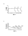
図3は定電流で充電を開始してからのキャパシタユニット11の電圧経時変化を表すグラフであり、横軸は時間、縦軸は電圧である。
FIG. 3 is a graph showing the change with time of the voltage of the
充電を開始すると、時間とともにキャパシタユニット11に電荷が蓄えられ、キャパシタユニット11の電圧が上昇していく。
When charging is started, electric charge is stored in the
この時、充電を途中で中断する。これにより、キャパシタユニット11の電圧が変化し、その内部抵抗分だけ降下する。
At this time, charging is interrupted halfway. As a result, the voltage of the
その後、充電を再開するのであるが、充電の中断前後で充電電圧が変化する性質を利用して、電圧降下幅をキャパシタユニット電圧検出手段17aにより求める。この電圧降下幅と、充電時におけるキャパシタユニット電流検出手段17bで求めた電流値を抵抗計算式(前者を後者で割る)に代入することにより、キャパシタユニット11の内部抵抗値を求めることができる。
Thereafter, charging is resumed, but the voltage drop width is obtained by the capacitor unit voltage detecting means 17a by utilizing the property that the charging voltage changes before and after the interruption of charging. The internal resistance value of the
なお、内部抵抗値は充電再開前後の電圧上昇幅から求めてもよい。 In addition, you may obtain | require an internal resistance value from the voltage rise width before and behind charge resumption.
このように充電を途中で中断することで、より正確な内部抵抗値を求めることができる。 Thus, by interrupting charging in the middle, a more accurate internal resistance value can be obtained.
充電再開後は、キャパシタユニット11の充電が完了するまでの充電区間中に充電電圧変化率(図3の傾き)をキャパシタ電圧検出手段17aで検出する。
After the resumption of charging, the charging voltage change rate (slope of FIG. 3) is detected by the capacitor
この際、充電電圧変化率はキャパシタユニット11における電圧が所定の電圧差(本実施の形態では2Vとした)を得るのに要した時間tを求めることによって決定した。
At this time, the charging voltage change rate was determined by obtaining a time t required for the voltage in the
なお、充電電圧変化率(傾き)は単位時間(1秒)当たりの電圧変化幅を測定するのが一般的であるが、この方法は次の理由で精度が悪かった。 The charging voltage change rate (slope) is generally measured by the voltage change width per unit time (1 second), but this method has poor accuracy for the following reason.
本実施の形態に用いたマイクロコンピュータ15は汎用の8ビットのものであるので、それに対応してキャパシタ電圧検出回路17aの電圧出力をデジタル変換して読み込むADコンバータ(図示せず)も10ビット程度のものを用いている。
Since the
従って、1秒間の電圧変化はわずかであるので、これを10ビットADコンバータで読み込むと量子化誤差が大きくなってしまう。 Therefore, since the voltage change per second is slight, if this is read by a 10-bit AD converter, the quantization error becomes large.
これを改善するため従来は複数回読み込んで平均化していたが、ソフト処理が複雑になる割には大きな精度向上が得られなかった。これは量子化誤差が大きすぎるためである。 In order to improve this, conventionally, reading and averaging were performed a plurality of times, but a large improvement in accuracy could not be obtained for the complicated software processing. This is because the quantization error is too large.
そこで、本実施の形態で用いたADコンバータでも精度よく検出できる2V程度の大きな所定電圧差を得るまでに要した時間を検出することで充電電圧変化率の高精度化を図った。時間の検出はADコンバータによる電圧検出より約1桁精度が良いので、この手法により充電電圧変化率を従来より1桁高精度に決定できた。 In view of this, the accuracy of the charge voltage change rate is improved by detecting the time required to obtain a large predetermined voltage difference of about 2 V that can be accurately detected by the AD converter used in the present embodiment. Since the time detection is better by about one digit accuracy than the voltage detection by the AD converter, the charge voltage change rate can be determined by one digit higher accuracy than before by this method.
このようにして得られた2V変化するまでの時間に、キャパシタユニット電流検出手段17bの出力から得られた充電電流を掛け、所定電圧(2V)で割ることで容量値Cを得ることができる。 The capacitance value C can be obtained by multiplying the charging time obtained from the output of the capacitor unit current detection means 17b by the time until the change of 2V obtained in this way and dividing by the predetermined voltage (2V).
すなわち、電荷Q=電圧V×容量値Cで表され、一方、電荷Q=電流A×時間tであるから、C=A×t/Vとなるので、この容量計算式により容量値Cが得られる。 That is, charge Q = voltage V × capacitance value C. On the other hand, since charge Q = current A × time t, C = A × t / V. Therefore, the capacitance value C is obtained by this capacity calculation formula. It is done.
次に、キャパシタ電圧検出手段17aの出力が充電終了電圧である12Vになると充電を完了する。
Next, the charging is completed when the output of the capacitor
なお、本実施の形態では、キャパシタユニット11の内部抵抗値、容量値は温度が0℃の時、例えばそれぞれ130mΩ、10Fであった。
In the present embodiment, the internal resistance value and capacitance value of the
内部抵抗値、容量値は充電完了後には上記のようにして測定することができないので、以後は充電中に得られたこれらの値を基にキャパシタユニット11の温度により推定している。その方法を以下に説明する。
Since the internal resistance value and the capacitance value cannot be measured as described above after the charging is completed, the internal resistance value and the capacitance value are estimated from the temperature of the
図4(a)はキャパシタユニット11の容量値の標準値における温度特性を示す。標準値とは多数の新品キャパシタユニット11の容量値を平均化したものである。従って、新品のキャパシタユニット11の容量値は図4(a)の温度特性線近くの値となる。
FIG. 4A shows the temperature characteristic at the standard value of the capacitance value of the
しかし、キャパシタユニット11を使い続けることにより劣化が進行すると、その容量値は徐々に小さくなっていく。よって、例えば本実施の形態で得られた0℃時に10Fという容量値は新品の容量値14Fに比べ4Fも小さいので、新品の状態から4F分の劣化が進んでいることになる。
However, as the deterioration progresses by continuing to use the
これを他の温度で比べてみても、図4(a)に示したとおり、新品との差は全て4Fであった。 Even when this was compared at other temperatures, as shown in FIG. 4A, the difference from the new product was all 4F.
このことから、図2のフローチャートのS2で測った容量値と図4(a)の特性図があれば、温度に関わらず新品との差が4Fと一定であるので、現在の容量値を推定することができる。 Therefore, if there is the capacitance value measured in S2 in the flowchart of FIG. 2 and the characteristic diagram of FIG. 4A, the difference between the new value is constant at 4F regardless of the temperature, and the current capacitance value is estimated. can do.
例えば、現在の温度が15℃であれば、15℃の標準容量値を図4(a)から求め(この場合、15F)、新品との差4Fを差し引くことで実際の容量値は11Fであると推定できる。 For example, if the current temperature is 15 ° C., the standard capacity value of 15 ° C. is obtained from FIG. 4A (in this case, 15F), and the actual capacity value is 11F by subtracting the difference 4F from the new product. Can be estimated.
このようにして、任意の温度下でのキャパシタユニット11の容量値を、その時の温度のみから推定することができる。なお、容量値の新品との差(本実施の形態では4F)を以後劣化補正値と呼び、これを図2のフローチャートのS3で求めておく。
In this way, the capacitance value of the
同様にして内部抵抗値も温度のみによって推定できる。この場合は図4(b)における0℃の内部抵抗値130mΩに対し、新品の平均内部抵抗値は60mΩであるから、両者の差(劣化補正値)=70mΩ分の内部抵抗値が増え、劣化が進んでいることになる。 Similarly, the internal resistance value can be estimated only by temperature. In this case, since the average new internal resistance value is 60 mΩ with respect to the internal resistance value of 130 mΩ at 0 ° C. in FIG. 4B, the difference between the two (deterioration correction value) = 70 mΩ increases, and the deterioration occurs. Is going on.
この値も図2のフローチャートのS2で求めた内部抵抗値と図4(b)から、内部抵抗値の劣化補正値としてS3で求めておく。 This value is also obtained in S3 as a deterioration correction value of the internal resistance value from the internal resistance value obtained in S2 of the flowchart of FIG. 2 and FIG. 4B.
次に、S2で求めた容量値Cや内部抵抗値Rcの少なくともいずれかが、あらかじめ求めたキャパシタユニット11の劣化判定値を満たさない場合(Cが劣化判定値より小さい場合、またはRcが劣化判定値より大きい場合)は(S4aのYes)、キャパシタユニット11が劣化したと判断し、マイクロコンピュータ15はその事実を通信出力端子9を介して電子制御部6に劣化異常信号を送信する(S5)。
Next, when at least one of the capacitance value C and the internal resistance value Rc obtained in S2 does not satisfy the deterioration determination value of the
S4aでNoの場合は、S1で求めた温度に応じて、S2で求めた容量値Cをキャパシタユニットの温度毎の劣化判定式(詳細な求め方は後述する)に代入することで、現在の温度に応じた判定基準値を計算する(S4b)。 In the case of No in S4a, by substituting the capacitance value C determined in S2 into the deterioration determination formula for each temperature of the capacitor unit (detailed method will be described later) according to the temperature determined in S1, the current A criterion value according to the temperature is calculated (S4b).
次に求めた前記判定基準値が内部抵抗値Rc以下であればキャパシタユニットが劣化していると判断し(S4cのYes)、S5を実行する。 Next, if the determined determination reference value is equal to or less than the internal resistance value Rc, it is determined that the capacitor unit has deteriorated (Yes in S4c), and S5 is executed.
このようにして、キャパシタユニット起動時に劣化判定式を用いて劣化を判定できるので、従来の有限個の劣化判定基準値データで判定するよりも高精度な判断が可能となる。 In this way, since the deterioration can be determined using the deterioration determination formula at the time of starting the capacitor unit, it is possible to make a determination with higher accuracy than the determination based on the conventional limited number of deterioration determination reference value data.
次に、S4cでNoの場合は車両使用中におけるキャパシタユニットの経時的な劣化を調べる。これにより所定時間毎に劣化判定ができるため、さらなる高精度判断が可能となる。 Next, in the case of No in S4c, the deterioration over time of the capacitor unit during use of the vehicle is examined. As a result, the deterioration can be determined every predetermined time, so that a higher accuracy can be determined.
この場合、現在の温度を基に内部抵抗値、容量値を以下のように推定する。 In this case, the internal resistance value and the capacitance value are estimated as follows based on the current temperature.
まず、キャパシタユニット11の近傍の温度を測定する(S6)。
First, the temperature in the vicinity of the
その結果、もし温度センサ18が断線または短絡などの故障をしていた場合は(S7のYes)温度がわからないので、本実施の形態では現在の温度をキャパシタユニット11の最高使用温度にセットし(S8)、以後この温度を基に後述する内部抵抗値の補正計算値などを求めてキャパシタユニット11の劣化判断を行うようにしている。
As a result, if the
なお、温度センサ18が故障した場合、現在の温度をキャパシタユニット11の最高使用温度(本実施の形態の場合30℃)にセットするのは、図7から明らかなように、本実施の形態ではキャパシタユニット11の使用温度が高いほど劣化の判定基準値が厳しくなるからである。
Note that when the
この結果、温度がわからない場合に最も負荷条件の厳しい温度を適用して劣化判定を行うことになるので、キャパシタユニット11の劣化判断の精度を損なう可能性(劣化しているのに正常と判断してしまう)を低減することができる。
As a result, when the temperature is not known, the deterioration determination is performed by applying the temperature with the severest load condition. Therefore, the accuracy of the deterioration determination of the
温度センサ18が正常であった場合(S7のNo)、現在の温度がキャパシタユニット11の使用温度範囲(本実施の形態では−30℃〜30℃)を超えていると(S9のYes)、キャパシタユニット11の劣化判断は行わない。
When the
これは、温度センサ18にサーミスタを用いているため、使用温度範囲を超えるとサーミスタの感度が極めて大きくなるか極めて小さくなり、温度測定の精度が悪くなってしまうのと、補助電源としての能力自身も保証できないためである。
This is because a thermistor is used for the
従って、車両用電源装置3が使用温度範囲内に入るまでは劣化判定をしないように制御している。
Therefore, control is performed so that the deterioration determination is not performed until the vehicle
S8、S9のNoのいずれの場合も現在のキャパシタユニット11の容量値、内部抵抗値の推定補正値を、S3で求めた劣化補正値(本実施の形態ではそれぞれ4F、70mΩ)およびS6で求めた温度から図4(a)、(b)の特性図を用いて求める(S10a)。
In both cases of S8 and S9, the estimated correction values of the current capacitance value and internal resistance value of the
具体的には、まず求めた温度に対応する容量値、内部抵抗値の標準値を図4(a)、(b)の特性図からそれぞれ求める。 Specifically, first, a standard value of a capacitance value and an internal resistance value corresponding to the obtained temperature is obtained from the characteristic diagrams of FIGS.
次に、各標準値に対し劣化補正値を、容量値の場合は差し引き、内部抵抗値の場合は加えることで、容量補正計算値Ccal、および内部抵抗補正計算値Rcalを求める。 Next, the capacitance correction calculation value Ccal and the internal resistance correction calculation value Rcal are obtained by subtracting the deterioration correction value for each standard value in the case of the capacitance value and adding it in the case of the internal resistance value.
次に、後述するキャパシタユニット11の劣化判定式に容量補正計算値Ccalを代入し判定基準値を求める(S10b)。
Next, a capacitance reference value is calculated by substituting the capacitance correction calculation value Ccal into a deterioration determination formula of the
なお、容量値に対する各温度での劣化判定式の計算結果をグラフ化したものを図5に示す。図5で横軸は容量値、縦軸は内部抵抗値(判定基準値)をそれぞれ示す。 FIG. 5 is a graph showing the calculation result of the deterioration judgment formula at each temperature with respect to the capacitance value. In FIG. 5, the horizontal axis represents the capacitance value, and the vertical axis represents the internal resistance value (judgment reference value).
図5より現在の温度に対応して得られた判定基準値が内部抵抗補正計算値Rcal以下の場合はキャパシタユニット11が劣化したと判断し(S10cのYes)、S5と同様に劣化異常信号を送信する(S10d)。
From FIG. 5, when the determination reference value obtained corresponding to the current temperature is equal to or less than the internal resistance correction calculated value Rcal, it is determined that the
その後、劣化の有無にかかわらずS6に戻って、以下同様の動作を繰り返す。これにより、所定時間毎に劣化判定を行うことができる。 Thereafter, the process returns to S6 regardless of the presence or absence of deterioration, and thereafter the same operation is repeated. Thereby, deterioration determination can be performed for every predetermined time.
次に、マイクロコンピュータ処理の時間制御に基づいた具体的動作について、図6のフローチャートを用いて説明する。 Next, a specific operation based on the time control of the microcomputer processing will be described with reference to the flowchart of FIG.
一般にマイクロコンピュータの制御においては、常にメインプログラム制御は、規定の内部周期(通常数ミリ秒のオーダーで、本実施の形態では6ミリ秒)で回っており、ある周期内にイベント発生など都度処理が必要な場合、その対応処理を行い、その後次の周期を待つという、処理の時間制御を行っている。
In general, in the control of a microcomputer, the main program control always rotates in a prescribed internal cycle (usually on the order of several milliseconds, in this
従って、図2で説明した動作は全て内部周期内毎に処理が順次行われている。 Therefore, all the operations described in FIG. 2 are sequentially performed every internal cycle.
具体的には図6において、まずイグニッションスイッチ2をオンにすることによりマイクロコンピュータ15に電源が供給されると、イニシャル処理を行う(S11)。
Specifically, in FIG. 6, when power is supplied to the
次に、電子制御部6とマイクロコンピュータ15が信号を送受信する際にあらかじめ決定した内部周期が経過したかを判断する(S12)。
Next, it is determined whether a predetermined internal period has elapsed when the
もし内部周期分経過していなければ(S12のNo)、再びS12に戻り、内部周期が経過するまで待つ。 If the internal period has not elapsed (No in S12), the process returns to S12 again and waits until the internal period elapses.
内部周期が経過すれば(S12のYes)、図2で説明した入力処理や車両用電源装置制御処理に加え、通信信号処理、ダイアグノーシス処理等の各種処理ルーチンを順次実行する(S13)。 If the internal cycle has elapsed (Yes in S12), various processing routines such as communication signal processing and diagnosis processing are sequentially executed in addition to the input processing and vehicle power supply device control processing described in FIG. 2 (S13).
次に劣化判定を行うための計算(図2のS10)をS14で行うが、ここでこの計算処理方法について詳細を以下に説明する。 Next, a calculation for determining the deterioration (S10 in FIG. 2) is performed in S14. The details of this calculation processing method will be described below.
今、バッテリ1の電圧が既定値(9.5V)より下がり、車両用電源装置3が動作して運転者が車両制動を行った場合を考える。
Consider a case where the voltage of the
キャパシタユニット11の電圧は車両用電源装置3の動作前にVstrであったものが、動作により一定負荷電流Icntが時間tだけ流れ、動作後の電圧がVendになったとする。
Although the voltage of the
この場合、負荷要求上、Vendは最低電圧Vmin以上でなくてはならない。
よって(1)式を満たす必要がある。
In this case, Vend must be equal to or higher than the minimum voltage Vmin due to load requirements.
Therefore, it is necessary to satisfy the expression (1).
Vend≧Vmin (1)
一方、キャパシタユニット11の電圧降下ΔVは
ΔV=Vstr−Vend (2)
であるので、(1)式を代入して
ΔV≦Vstr−Vmin (3)
となる。
Vend ≧ Vmin (1)
On the other hand, the voltage drop ΔV of the
ΔV = Vstr−Vend (2)
Therefore, substituting equation (1)
ΔV ≦ Vstr−Vmin (3)
It becomes.
電圧降下ΔVは車両制動によるもの以外に配線系統によるものやキャパシタの内部抵抗によるものの和として表される。 The voltage drop ΔV is expressed as the sum of the voltage drop ΔV due to the wiring system and the capacitor internal resistance in addition to the vehicle braking.
車両制動による電圧降下Vloadはキャパシタユニット11の電荷量をQ、容量値をCとすると、次式で表される。
The voltage drop Vload due to vehicle braking is expressed by the following equation, where Q is the charge amount of the
Q=C・Vload
∴Vload=Q/C (4)
ここで、電荷量Qは車両制動により消費されるので、
Q=Icnt・t (5)
となる。よって、(5)式を(4)式に代入して
Vload=(Icnt・t)/C (6)
次に、配線系統による電圧降下Vdrはダイオードのように電流依存が少ない一定の電圧降下Vfと配線抵抗やスイッチング素子の抵抗などの総抵抗Rlossより、次式で表される。
Q = C ・ Vload
∴Vload = Q / C (4)
Here, since the charge amount Q is consumed by vehicle braking,
Q = Icnt · t (5)
It becomes. Therefore, substituting equation (5) into equation (4)
Vload = (Icnt · t) / C (6)
Next, the voltage drop Vdr due to the wiring system is expressed by the following equation from a constant voltage drop Vf that is less dependent on current like a diode and the total resistance Rloss such as the resistance of the wiring resistance and the switching element.
Vdr=Vf+(Rloss・Icnt) (7)
次に、キャパシタの内部抵抗による電圧降下Vcは、キャパシタユニット11の内部抵抗値をRcとすると、
Vc=Rc・Icnt (8)
以上より、全体の電圧降下ΔVは
ΔV=Vc+Vload+Vdr
=Rc・Icnt+(Icnt・t)/C+Vdr (9)
(9)式を(3)式に代入すると、
(Vstr−Vmin)
≧Rc・Icnt+(Icnt・t)/C+Vdr (10)
Rcの式に直すと、
Rc≦((Vstr−Vmin)−Vdr
−(Icnt・t)/C)/Icnt (11)
ここで、温度が一定ならVstr、Vmin、Vdr、Icnt、tは一定であるので、(11)式は簡単には(12)式のように表される。
Vdr = Vf + (Rloss · Icnt) (7)
Next, the voltage drop Vc due to the internal resistance of the capacitor is given by Rc as the internal resistance value of the
Vc = Rc · Icnt (8)
From the above, the overall voltage drop ΔV is
ΔV = Vc + Vload + Vdr
= Rc · Icnt + (Icnt · t) / C + Vdr (9)
Substituting equation (9) into equation (3),
(Vstr-Vmin)
≧ Rc · Icnt + (Icnt · t) / C + Vdr (10)
Converting to the equation of Rc,
Rc ≦ ((Vstr−Vmin) −Vdr
− (Icnt · t) / C) / Icnt (11)
Here, since Vstr, Vmin, Vdr, Icnt, and t are constant if the temperature is constant, the expression (11) is simply expressed as the expression (12).
Rc≦A−B/C (12)
なお、係数A、Bは定数である。
Rc ≦ A−B / C (12)
The coefficients A and B are constants.
(12)式より負荷を満たすためのキャパシタユニット11の容量値Cと内部抵抗値Rcの関係式が得られた。すなわち、理論的にはCとRcは(12)式を満たしていなければならないことがわかる。
The relational expression between the capacitance value C of the
この(12)式から次のようにしてキャパシタユニット11の劣化を判断できる。
From this equation (12), the deterioration of the
すなわち、例えば図2のS4bでCを(12)式に代入する。この時、Rcが(12)式を満たせば、つまり、Rcの方が(12)式の右辺を計算した結果である判定基準値以下であれば、キャパシタユニット11は正常であり、(12)式を満たさなければキャパシタユニット11は劣化したと判断できる。
That is, for example, C is substituted into equation (12) in S4b of FIG. At this time, if Rc satisfies the equation (12), that is, if Rc is equal to or less than the criterion value that is the result of calculating the right side of the equation (12), the
同様に、図2のS10aでCとRcの補正計算値Ccal、Rcalを求め、次にCcalを(12)式に代入する(S10b)。この時、Rcalが(12)式を満たせば、つまり、Rcalの方が(12)式の右辺を計算した結果である判定基準値以下であれば、キャパシタユニット11は正常であり、(12)式を満たさなければキャパシタユニット11は劣化したと判断できる。
Similarly, C and Rc correction calculation values Ccal and Rcal are obtained in S10a of FIG. 2, and then Ccal is substituted into equation (12) (S10b). At this time, if Rcal satisfies the equation (12), that is, if Rcal is equal to or less than the criterion value that is the result of calculating the right side of the equation (12), the
以上の計算からキャパシタユニット11の劣化判定式を得ることができた。
From the above calculation, the deterioration judgment formula of the
なお、定数A、Bは実際にはキャパシタユニット11のRcやCの測定誤差等のマージンを考慮して、劣化判定が厳しくなる方向に設定している。具体的には内部抵抗値Rcは20%、容量値Cは15%のマージンをそれぞれ加味し、
Rc≦0.8・(A−(B/C)・1.15)
≦A’−B’/C (13)
とした。なお、A’、B’はマージン加味後の定数である。
It should be noted that the constants A and B are actually set in such a direction that the deterioration determination becomes severe in consideration of a margin such as a measurement error of Rc and C of the
Rc ≦ 0.8 · (A− (B / C) · 1.15)
≦ A′−B ′ / C (13)
It was. A ′ and B ′ are constants after adding a margin.
また、A’、B’は温度により変動する値(温度係数)であるので、各温度におけるA’、B’をROMに記憶するようにした。このデータは従来の図7に示したような劣化判定基準値データに比べてはるかに少ないため、従来以上にROMの記憶容量を増やすことなく記憶させることができる。 Further, since A ′ and B ′ are values (temperature coefficients) that vary depending on the temperature, A ′ and B ′ at each temperature are stored in the ROM. Since this data is much less than the conventional deterioration judgment reference value data as shown in FIG. 7, it can be stored without increasing the storage capacity of the ROM more than in the past.
このように各温度におけるA’、B’を用いて(13)式(劣化判定式)をグラフ化した結果(図5)より、温度毎に任意の容量値に対する劣化限界内部抵抗値(判定基準値)を正確に知ることができ、図7のような飛び飛びの値に比べ格段に(具体的には1桁)劣化判定精度が向上することがわかる。 Thus, from the result (FIG. 5) of graphing the equation (13) (degradation judgment equation) using A ′ and B ′ at each temperature, the degradation limit internal resistance value (determination criterion) for an arbitrary capacitance value for each temperature. Value) can be obtained accurately, and it can be seen that the deterioration determination accuracy is significantly improved (specifically, one digit) as compared with the jump value as shown in FIG.
以上の計算を用いて図6のフローチャートに戻り、マイクロコンピュータ制御による実際の劣化判定手法を説明する。 Returning to the flowchart of FIG. 6 using the above calculation, an actual deterioration determination method by microcomputer control will be described.
各種処理ルーチン(S13)を実行後、前記した容量値C、内部抵抗値Rcの補正計算値Ccal、Rcalを用いて劣化判定を行う。 After executing the various processing routines (S13), the deterioration determination is performed using the correction calculation values Ccal and Rcal of the capacitance value C and the internal resistance value Rc.
ここで、簡単にはそのまま(13)式に容量補正計算値Ccalを代入して得られた判定基準値と内部抵抗補正計算値Rcalとを比較すればよいが、計算に当たってはCcalの逆数(除算)を計算する必要がある。マイクロコンピュータにはコスト制約から汎用の8ビットマイクロコンピュータを用いているので、除算を実行すると計算時間がかかってしまう。 Here, simply, the determination reference value obtained by substituting the capacitance correction calculation value Ccal into the equation (13) may be compared with the internal resistance correction calculation value Rcal, but in the calculation, the reciprocal of Ccal (division) ) Need to be calculated. Since a general-purpose 8-bit microcomputer is used as a microcomputer due to cost constraints, calculation time is required when division is executed.
特に高精度な劣化判定を行うには除算の有効桁数を増やす必要があるが、そのためにマイクロコンピュータでの計算を倍精度、16ビット(1ワード)に拡張して除算を行った場合、1ワード同士の除算用アルゴリズムを作成し実行すると、極めて計算に時間がかかることがわかった。 In particular, it is necessary to increase the number of effective digits for division in order to perform highly accurate deterioration determination. For this reason, when division is performed with the microcomputer calculation extended to double precision, 16 bits (one word), 1 It was found that computation was extremely time-consuming when a word division algorithm was created and executed.
一方で、車両用電源装置は車両制動用の電子制御部コンピュータと通信によりデータ交換を行うなど、マイクロコンピュータは内部周期に定められたタイミングのデータを生成する必要がある。 On the other hand, the microcomputer needs to generate data at a timing determined in the internal cycle, such as the vehicle power supply device exchanging data with the electronic control unit computer for vehicle braking.
従って、(13)式の高精度な計算(特に1ワード同士の除算)を実行してしまうと内部周期内に計算が終了せず、制御周期が乱れ生成データがずれてしまう。 Therefore, if the highly accurate calculation (especially division of one word) of the equation (13) is executed, the calculation is not completed within the internal cycle, and the control cycle is disturbed and the generated data is shifted.
そこで、(13)式の除算を内部周期内に収まる計算時間になるように分割したプログラムを作成し、それを順次実行するようにした。この手法を図6のフローチャート(S14)を用いて説明する。 Therefore, a program is created by dividing the division of equation (13) so that the calculation time is within the internal period, and the program is executed sequentially. This method will be described with reference to the flowchart (S14) in FIG.
まず、計算の分割を本実施の形態では6分割とした。すなわち、6つに分割した除算ルーチンを全て順に実行し終わると1ワード同士の高精度な除算を含め(13)式の計算が終了する。 First, the calculation is divided into six in this embodiment. That is, when all the division routines divided into six are executed in order, the calculation of equation (13) is completed, including high-precision division of one word.
実際には、次にどの計算を行うかをカウントNの値で判断する(S14a)。 Actually, which calculation is performed next is determined based on the value of the count N (S14a).
もしN=1なら、最初の分割された計算処理1を実行する(S14b)。例えば、計算処理1では(13)式を計算するのに必要な定数A’、B’を温度に応じてROMから読み込む動作を行う。
If N = 1, the first divided
この後、カウントNを増分(1加える)して、計算が完了したか否かを判断する(S14c)。 Thereafter, the count N is incremented (added by 1) to determine whether or not the calculation is completed (S14c).
計算が完了していなければ、すなわちNが6でなければ(S14cのNo)、内部周期経過待ちに戻る(S12)。 If the calculation is not completed, that is, if N is not 6 (No in S14c), the process returns to waiting for the internal cycle (S12).
同様にして、S14aでカウントNが2であれば2番目に分割された計算処理2を実行する(S14d)。ここでは例えば(13)式のB’/Cの計算を1ワード同士で行うためのアルゴリズムのうち最初の1/4を実行する。
Similarly, if the count N is 2 in S14a, the
その後、カウントNを増分してS14cで計算完了を判断するが、この場合まだ終わっていないので(S14cのNo)、S12に戻る。 Thereafter, the count N is incremented and it is determined in S14c that the calculation is complete. In this case, the calculation is not completed yet (No in S14c), and the process returns to S12.
このようにして、カウントNに応じて計算処理3(S14e)以降を順次計算していく。 In this way, calculation processing 3 (S14e) and subsequent steps are sequentially calculated according to the count N.
最後にS14aでカウントNが6になると、最後の計算処理6を実行する(S14f)。ここでは例えばB’/Cの計算は計算処理5(図示せず)で終了しているので、A’−B’/Cを求める。これにより内部抵抗の計算値、すなわち判定基準値を得ることができる。
Finally, when the count N reaches 6 in S14a, the
このように計算を分割して行うようにしたことで、内部周期内に各計算が収まるため、内部周期に決められたタイミングのデータをずれることなく生成することが可能となる。 Since the calculations are divided and performed in this way, each calculation is accommodated within the internal period, and therefore, it is possible to generate data at a timing determined in the internal period without shifting.
次に計算が完了したので(S14cのYes)、得られた判定基準値とRcの補正計算値を比較することにより、劣化の判定処理を行う(S14g)。すなわち、計算で得られた判定基準値が内部抵抗値Rcal以下なら劣化していると判断する(劣化ダイアグノーシス処理)。その後、S12に戻る。 Next, since the calculation is completed (Yes in S14c), deterioration determination processing is performed by comparing the obtained determination reference value and the corrected calculation value of Rc (S14g). That is, if the determination reference value obtained by the calculation is equal to or less than the internal resistance value Rcal, it is determined that the deterioration has occurred (deterioration diagnosis process). Thereafter, the process returns to S12.
以上の動作を繰り返すことにより、キャパシタユニット11の劣化を判定している。
The deterioration of the
なお、本実施の形態では(13)式の計算をマイクロコンピュータ15の内部制御周期毎に分割実行する例を示したが、これは他の計算(例えばCやRcの温度による補正計算など)でも計算時間がかかる場合には同様に分割実行すればよい。
In the present embodiment, an example is shown in which the calculation of equation (13) is divided and executed for each internal control period of the
以上の構成、動作により、劣化判定式を計算しても制御周期の乱れや生成データへの影響を与えることなく、高精度な測定や計算が可能となることから、キャパシタユニット11の劣化判定精度を従来に比べ1桁以上向上することができる。 With the above configuration and operation, even if the deterioration determination formula is calculated, it is possible to perform highly accurate measurement and calculation without disturbing the control cycle or affecting the generated data. Can be improved by an order of magnitude or more.
なお、本実施の形態では容量値や内部抵抗値を充電時に求めたが、これはイグニッションスイッチ2をオフにしてキャパシタユニット11の補助電力を放電する際に充電時と同様の手法で求めて記憶しておいてもよい。
In the present embodiment, the capacitance value and the internal resistance value are obtained at the time of charging, but this is obtained and stored by the same method as at the time of charging when the
本発明にかかる車両用電源装置によれば、キャパシタユニットの劣化判定精度を極めて向上できるので、特に、車両の制動を電気的に行う電子ブレーキシステムの非常用電源等として有用である。 According to the vehicle power supply device of the present invention, the accuracy of determining the deterioration of the capacitor unit can be greatly improved, so that it is particularly useful as an emergency power supply for an electronic brake system that electrically brakes the vehicle.
3 車両用電源装置
11 キャパシタユニット
13 充電回路
14 放電回路
15 マイクロコンピュータ
16 スイッチ
17a キャパシタユニット電圧検出手段
17b キャパシタユニット電流検出手段
18 温度センサ
DESCRIPTION OF
Claims (6)
前記キャパシタユニット近傍の温度を測定する温度センサと、
前記キャパシタユニットを充電する充電回路と、
前記キャパシタユニットの電流を測定するキャパシタユニット電流検出手段と、
前記キャパシタユニットの電圧を測定するキャパシタユニット電圧検出手段と、
前記補助電力の必要時に前記キャパシタユニットから出力するよう切り替えるスイッチと、
前記温度センサ、前記充電回路、前記キャパシタユニット電流検出手段、前記キャパシタユニット電圧検出手段、前記スイッチが電気的に接続された制御部を有し、
前記キャパシタユニットを定電流で充電または放電する際に、
途中で充電または放電を中断、再開し、その時の前記キャパシタユニットの中断、再開前後の充電電圧または放電電圧の変化を前記キャパシタユニット電圧検出手段により検出するとともに、前記キャパシタユニット電流検出手段の出力とから前記キャパシタユニットの内部抵抗値を求め、
充電または放電の区間中における前記キャパシタユニットの充電または放電の電圧変化率と、前記キャパシタユニット電流検出手段の出力から前記キャパシタユニットの容量値を求め、
その後、前記温度センサから求めた温度に応じて、前記容量値から前記キャパシタユニットの劣化判定式により判定基準値を計算し、
前記判定基準値が前記内部抵抗値以下であれば、前記キャパシタユニットが劣化していると判断する際に、前記温度センサが断線または短絡した場合は前記キャパシタユニット使用温度範囲における、最も負荷条件の厳しい温度を適用して前記キャパシタユニットの劣化を判断する車両用電源装置。 A capacitor unit comprising a plurality of capacitors for storing auxiliary power;
A temperature sensor for measuring the temperature in the vicinity of the capacitor unit;
A charging circuit for charging the capacitor unit;
Capacitor unit current detection means for measuring the current of the capacitor unit;
Capacitor unit voltage detection means for measuring the voltage of the capacitor unit;
A switch for switching to output from the capacitor unit when the auxiliary power is required;
The temperature sensor, the charging circuit, the capacitor unit current detection means, the capacitor unit voltage detection means, and a controller to which the switch is electrically connected,
When charging or discharging the capacitor unit with a constant current,
Charging or discharging is interrupted and restarted halfway, and the capacitor unit voltage detecting means detects a change in the charging voltage or discharging voltage before and after the interruption or resumption of the capacitor unit, and the output of the capacitor unit current detecting means To determine the internal resistance value of the capacitor unit from
Obtaining the capacitance value of the capacitor unit from the voltage change rate of charging or discharging of the capacitor unit during the charging or discharging period and the output of the capacitor unit current detection means;
Thereafter, according to the temperature obtained from the temperature sensor, a determination reference value is calculated from the capacitance value by a deterioration determination formula of the capacitor unit,
If the determination reference value is equal to or less than the internal resistance value, when the temperature sensor is disconnected or short-circuited when it is determined that the capacitor unit has deteriorated , A power supply device for a vehicle that determines deterioration of the capacitor unit by applying severe temperature .
前記判定基準値が前記内部抵抗補正計算値以下であれば、前記キャパシタユニットが劣化していると判断する際に、
前記各計算のうち少なくとも1つを前記制御部の内部制御周期毎に分割実行する請求項1に記載の車両用電源装置。 The internal resistance correction calculation value and the capacitance correction calculation value are obtained by performing correction calculation of the internal resistance value and the capacitance value according to the temperature obtained from the temperature sensor every predetermined time, and the capacitor unit is calculated from the capacitance correction calculation value. Calculate the criterion value using the degradation criterion,
If the determination reference value is equal to or less than the internal resistance correction calculation value, when determining that the capacitor unit is deteriorated,
The vehicle power supply device according to claim 1, wherein at least one of the calculations is divided and executed for each internal control period of the control unit.
Priority Applications (5)
| Application Number | Priority Date | Filing Date | Title |
|---|---|---|---|
| JP2005215352A JP4797487B2 (en) | 2005-07-26 | 2005-07-26 | Vehicle power supply |
| US11/916,691 US7680612B2 (en) | 2005-07-26 | 2006-07-26 | Vehicle power supply device |
| EP06781630.6A EP1889751B1 (en) | 2005-07-26 | 2006-07-26 | Vehicle power supply device |
| PCT/JP2006/314718 WO2007013481A1 (en) | 2005-07-26 | 2006-07-26 | Vehicle power supply device |
| CN2006800271219A CN101228048B (en) | 2005-07-26 | 2006-07-26 | Vehicle power supply device |
Applications Claiming Priority (1)
| Application Number | Priority Date | Filing Date | Title |
|---|---|---|---|
| JP2005215352A JP4797487B2 (en) | 2005-07-26 | 2005-07-26 | Vehicle power supply |
Publications (3)
| Publication Number | Publication Date |
|---|---|
| JP2007030649A JP2007030649A (en) | 2007-02-08 |
| JP2007030649A5 JP2007030649A5 (en) | 2008-09-04 |
| JP4797487B2 true JP4797487B2 (en) | 2011-10-19 |
Family
ID=37683371
Family Applications (1)
| Application Number | Title | Priority Date | Filing Date |
|---|---|---|---|
| JP2005215352A Active JP4797487B2 (en) | 2005-07-26 | 2005-07-26 | Vehicle power supply |
Country Status (5)
| Country | Link |
|---|---|
| US (1) | US7680612B2 (en) |
| EP (1) | EP1889751B1 (en) |
| JP (1) | JP4797487B2 (en) |
| CN (1) | CN101228048B (en) |
| WO (1) | WO2007013481A1 (en) |
Families Citing this family (14)
| Publication number | Priority date | Publication date | Assignee | Title |
|---|---|---|---|---|
| JP5261951B2 (en) * | 2007-03-23 | 2013-08-14 | パナソニック株式会社 | Power storage device |
| US8860244B2 (en) * | 2008-09-08 | 2014-10-14 | Autonetworks Technologies, Ltd. | Vehicle power supply apparatus |
| JP5277819B2 (en) * | 2008-09-16 | 2013-08-28 | パナソニック株式会社 | Power storage device |
| JP5381086B2 (en) | 2008-10-06 | 2014-01-08 | 日本電気株式会社 | Communication system and communication control method |
| JP5193897B2 (en) * | 2009-02-09 | 2013-05-08 | 山洋電気株式会社 | Uninterruptible power supply using electric double layer capacitor |
| KR20110134019A (en) * | 2010-06-08 | 2011-12-14 | 현대자동차주식회사 | Degradation diagnosis method of battery cell of vehicle |
| JP5353861B2 (en) * | 2010-10-29 | 2013-11-27 | オムロン株式会社 | Sensor device |
| KR20120120706A (en) * | 2011-04-25 | 2012-11-02 | 삼성전자주식회사 | Auxiliary power supply and user device including auxiliary power supply |
| JP5880008B2 (en) * | 2011-12-19 | 2016-03-08 | マツダ株式会社 | In-vehicle power supply controller |
| US9037424B2 (en) | 2012-05-01 | 2015-05-19 | Caterpillar Inc. | Systems and methods for detecting ultracapacitor cell short circuits |
| US10033213B2 (en) * | 2014-09-30 | 2018-07-24 | Johnson Controls Technology Company | Short circuit wake-up system and method for automotive battery while in key-off position |
| ITUB20154611A1 (en) | 2015-10-13 | 2017-04-13 | Ultraflex Spa | Directional control system of a boat |
| JP6357722B2 (en) * | 2015-12-22 | 2018-07-18 | 株式会社ケーヒン | Discharge control device |
| CN112557862A (en) * | 2020-11-26 | 2021-03-26 | 徐州天力电子科技有限公司 | Controller with power supply capacitor detection device |
Family Cites Families (10)
| Publication number | Priority date | Publication date | Assignee | Title |
|---|---|---|---|---|
| EP1326085A3 (en) * | 1993-11-08 | 2007-11-14 | Honda Giken Kogyo Kabushiki Kaisha | Apparatus for inspecting electric component for inverter circuit |
| JPH08214402A (en) | 1995-02-03 | 1996-08-20 | Hitachi Ltd | Protective device and control method of motor car |
| JP3351171B2 (en) * | 1995-04-13 | 2002-11-25 | トヨタ自動車株式会社 | Capacitor capacity diagnostic circuit |
| US6356086B1 (en) * | 1999-04-12 | 2002-03-12 | Sencore, Inc. | Method and apparatus for the in-circuit testing of a capacitor |
| JP2002165357A (en) * | 2000-11-27 | 2002-06-07 | Canon Inc | Power converter and its control method, and power generating system |
| DE10116463A1 (en) * | 2001-04-03 | 2002-10-10 | Isad Electronic Sys Gmbh & Co | System for storing electrical energy, and method for operating such an energy storage system |
| JP4085682B2 (en) * | 2002-04-17 | 2008-05-14 | トヨタ自動車株式会社 | Vehicle power management method, vehicle power management device, and vehicle power management program |
| JP2004303756A (en) | 2003-03-28 | 2004-10-28 | Nissan Diesel Motor Co Ltd | Electric storage device |
| JP4385664B2 (en) * | 2003-07-08 | 2009-12-16 | パナソニック株式会社 | Vehicle power supply |
| JP4569886B2 (en) * | 2003-12-25 | 2010-10-27 | 株式会社大泉製作所 | Manufacturing method of temperature sensor |
-
2005
- 2005-07-26 JP JP2005215352A patent/JP4797487B2/en active Active
-
2006
- 2006-07-26 WO PCT/JP2006/314718 patent/WO2007013481A1/en active Application Filing
- 2006-07-26 CN CN2006800271219A patent/CN101228048B/en active Active
- 2006-07-26 US US11/916,691 patent/US7680612B2/en active Active
- 2006-07-26 EP EP06781630.6A patent/EP1889751B1/en active Active
Also Published As
| Publication number | Publication date |
|---|---|
| CN101228048A (en) | 2008-07-23 |
| US7680612B2 (en) | 2010-03-16 |
| EP1889751A1 (en) | 2008-02-20 |
| CN101228048B (en) | 2010-06-16 |
| JP2007030649A (en) | 2007-02-08 |
| EP1889751A4 (en) | 2013-04-10 |
| WO2007013481A1 (en) | 2007-02-01 |
| EP1889751B1 (en) | 2014-02-26 |
| US20090119034A1 (en) | 2009-05-07 |
Similar Documents
| Publication | Publication Date | Title |
|---|---|---|
| JP4797487B2 (en) | Vehicle power supply | |
| JP4797488B2 (en) | Vehicle power supply | |
| JP5017084B2 (en) | Battery control method and system | |
| JP5529877B2 (en) | Battery system | |
| JP4807058B2 (en) | Vehicle power supply | |
| JP4385664B2 (en) | Vehicle power supply | |
| EP1801606B1 (en) | Method for compensating state of charge of battery, battery management system using the method, and hybrid vehicle having the battery management system | |
| US9755281B2 (en) | Method for connecting battery cells in a battery, battery, and monitoring device | |
| JP4853021B2 (en) | Analog-to-digital converter and power supply for vehicle using the same | |
| JP2009148126A (en) | Accumulation device | |
| EP3245095B1 (en) | Method and device for controlling an electric or a hybrid electric vehicle | |
| JP2013176197A (en) | Power supply device | |
| JP4897976B2 (en) | Method and apparatus for detecting state of power storage device | |
| CN110462964B (en) | Power storage device for vehicle | |
| GB2261735A (en) | Battery monitoring and management system | |
| JP2007131133A (en) | Power source device for vehicle | |
| WO2015022731A1 (en) | Battery monitoring apparatus, battery system, and vehicle control system | |
| WO2005050811A1 (en) | Power supply for vehicle | |
| CN113631938A (en) | Method and system for detecting connection failure of parallel battery cells | |
| JP5277819B2 (en) | Power storage device | |
| CN116034046A (en) | Power storage device, power storage system, internal resistance estimation method, and computer program |
Legal Events
| Date | Code | Title | Description |
|---|---|---|---|
| A521 | Written amendment |
Free format text: JAPANESE INTERMEDIATE CODE: A523 Effective date: 20080717 |
|
| A621 | Written request for application examination |
Free format text: JAPANESE INTERMEDIATE CODE: A621 Effective date: 20080717 |
|
| RD01 | Notification of change of attorney |
Free format text: JAPANESE INTERMEDIATE CODE: A7421 Effective date: 20091126 |
|
| TRDD | Decision of grant or rejection written | ||
| A01 | Written decision to grant a patent or to grant a registration (utility model) |
Free format text: JAPANESE INTERMEDIATE CODE: A01 Effective date: 20110705 |
|
| A01 | Written decision to grant a patent or to grant a registration (utility model) |
Free format text: JAPANESE INTERMEDIATE CODE: A01 |
|
| A61 | First payment of annual fees (during grant procedure) |
Free format text: JAPANESE INTERMEDIATE CODE: A61 Effective date: 20110718 |
|
| FPAY | Renewal fee payment (event date is renewal date of database) |
Free format text: PAYMENT UNTIL: 20140812 Year of fee payment: 3 |
|
| R151 | Written notification of patent or utility model registration |
Ref document number: 4797487 Country of ref document: JP Free format text: JAPANESE INTERMEDIATE CODE: R151 |
|
| FPAY | Renewal fee payment (event date is renewal date of database) |
Free format text: PAYMENT UNTIL: 20140812 Year of fee payment: 3 |