JP4794732B2 - Biodegradable stent - Google Patents
Biodegradable stent Download PDFInfo
- Publication number
- JP4794732B2 JP4794732B2 JP2000389400A JP2000389400A JP4794732B2 JP 4794732 B2 JP4794732 B2 JP 4794732B2 JP 2000389400 A JP2000389400 A JP 2000389400A JP 2000389400 A JP2000389400 A JP 2000389400A JP 4794732 B2 JP4794732 B2 JP 4794732B2
- Authority
- JP
- Japan
- Prior art keywords
- stent
- outer layer
- inner core
- glycolide
- lactide
- Prior art date
- Legal status (The legal status is an assumption and is not a legal conclusion. Google has not performed a legal analysis and makes no representation as to the accuracy of the status listed.)
- Expired - Fee Related
Links
Images


Classifications
-
- A—HUMAN NECESSITIES
- A61—MEDICAL OR VETERINARY SCIENCE; HYGIENE
- A61L—METHODS OR APPARATUS FOR STERILISING MATERIALS OR OBJECTS IN GENERAL; DISINFECTION, STERILISATION OR DEODORISATION OF AIR; CHEMICAL ASPECTS OF BANDAGES, DRESSINGS, ABSORBENT PADS OR SURGICAL ARTICLES; MATERIALS FOR BANDAGES, DRESSINGS, ABSORBENT PADS OR SURGICAL ARTICLES
- A61L31/00—Materials for other surgical articles, e.g. stents, stent-grafts, shunts, surgical drapes, guide wires, materials for adhesion prevention, occluding devices, surgical gloves, tissue fixation devices
- A61L31/14—Materials characterised by their function or physical properties, e.g. injectable or lubricating compositions, shape-memory materials, surface modified materials
- A61L31/148—Materials at least partially resorbable by the body
-
- A—HUMAN NECESSITIES
- A61—MEDICAL OR VETERINARY SCIENCE; HYGIENE
- A61F—FILTERS IMPLANTABLE INTO BLOOD VESSELS; PROSTHESES; DEVICES PROVIDING PATENCY TO, OR PREVENTING COLLAPSING OF, TUBULAR STRUCTURES OF THE BODY, e.g. STENTS; ORTHOPAEDIC, NURSING OR CONTRACEPTIVE DEVICES; FOMENTATION; TREATMENT OR PROTECTION OF EYES OR EARS; BANDAGES, DRESSINGS OR ABSORBENT PADS; FIRST-AID KITS
- A61F2/00—Filters implantable into blood vessels; Prostheses, i.e. artificial substitutes or replacements for parts of the body; Appliances for connecting them with the body; Devices providing patency to, or preventing collapsing of, tubular structures of the body, e.g. stents
- A61F2/82—Devices providing patency to, or preventing collapsing of, tubular structures of the body, e.g. stents
- A61F2/86—Stents in a form characterised by the wire-like elements; Stents in the form characterised by a net-like or mesh-like structure
- A61F2/88—Stents in a form characterised by the wire-like elements; Stents in the form characterised by a net-like or mesh-like structure the wire-like elements formed as helical or spiral coils
-
- A—HUMAN NECESSITIES
- A61—MEDICAL OR VETERINARY SCIENCE; HYGIENE
- A61L—METHODS OR APPARATUS FOR STERILISING MATERIALS OR OBJECTS IN GENERAL; DISINFECTION, STERILISATION OR DEODORISATION OF AIR; CHEMICAL ASPECTS OF BANDAGES, DRESSINGS, ABSORBENT PADS OR SURGICAL ARTICLES; MATERIALS FOR BANDAGES, DRESSINGS, ABSORBENT PADS OR SURGICAL ARTICLES
- A61L31/00—Materials for other surgical articles, e.g. stents, stent-grafts, shunts, surgical drapes, guide wires, materials for adhesion prevention, occluding devices, surgical gloves, tissue fixation devices
- A61L31/04—Macromolecular materials
- A61L31/041—Mixtures of macromolecular compounds
-
- A—HUMAN NECESSITIES
- A61—MEDICAL OR VETERINARY SCIENCE; HYGIENE
- A61L—METHODS OR APPARATUS FOR STERILISING MATERIALS OR OBJECTS IN GENERAL; DISINFECTION, STERILISATION OR DEODORISATION OF AIR; CHEMICAL ASPECTS OF BANDAGES, DRESSINGS, ABSORBENT PADS OR SURGICAL ARTICLES; MATERIALS FOR BANDAGES, DRESSINGS, ABSORBENT PADS OR SURGICAL ARTICLES
- A61L31/00—Materials for other surgical articles, e.g. stents, stent-grafts, shunts, surgical drapes, guide wires, materials for adhesion prevention, occluding devices, surgical gloves, tissue fixation devices
- A61L31/04—Macromolecular materials
- A61L31/06—Macromolecular materials obtained otherwise than by reactions only involving carbon-to-carbon unsaturated bonds
-
- A—HUMAN NECESSITIES
- A61—MEDICAL OR VETERINARY SCIENCE; HYGIENE
- A61L—METHODS OR APPARATUS FOR STERILISING MATERIALS OR OBJECTS IN GENERAL; DISINFECTION, STERILISATION OR DEODORISATION OF AIR; CHEMICAL ASPECTS OF BANDAGES, DRESSINGS, ABSORBENT PADS OR SURGICAL ARTICLES; MATERIALS FOR BANDAGES, DRESSINGS, ABSORBENT PADS OR SURGICAL ARTICLES
- A61L31/00—Materials for other surgical articles, e.g. stents, stent-grafts, shunts, surgical drapes, guide wires, materials for adhesion prevention, occluding devices, surgical gloves, tissue fixation devices
- A61L31/08—Materials for coatings
- A61L31/10—Macromolecular materials
-
- A—HUMAN NECESSITIES
- A61—MEDICAL OR VETERINARY SCIENCE; HYGIENE
- A61L—METHODS OR APPARATUS FOR STERILISING MATERIALS OR OBJECTS IN GENERAL; DISINFECTION, STERILISATION OR DEODORISATION OF AIR; CHEMICAL ASPECTS OF BANDAGES, DRESSINGS, ABSORBENT PADS OR SURGICAL ARTICLES; MATERIALS FOR BANDAGES, DRESSINGS, ABSORBENT PADS OR SURGICAL ARTICLES
- A61L31/00—Materials for other surgical articles, e.g. stents, stent-grafts, shunts, surgical drapes, guide wires, materials for adhesion prevention, occluding devices, surgical gloves, tissue fixation devices
- A61L31/14—Materials characterised by their function or physical properties, e.g. injectable or lubricating compositions, shape-memory materials, surface modified materials
-
- A—HUMAN NECESSITIES
- A61—MEDICAL OR VETERINARY SCIENCE; HYGIENE
- A61F—FILTERS IMPLANTABLE INTO BLOOD VESSELS; PROSTHESES; DEVICES PROVIDING PATENCY TO, OR PREVENTING COLLAPSING OF, TUBULAR STRUCTURES OF THE BODY, e.g. STENTS; ORTHOPAEDIC, NURSING OR CONTRACEPTIVE DEVICES; FOMENTATION; TREATMENT OR PROTECTION OF EYES OR EARS; BANDAGES, DRESSINGS OR ABSORBENT PADS; FIRST-AID KITS
- A61F2210/00—Particular material properties of prostheses classified in groups A61F2/00 - A61F2/26 or A61F2/82 or A61F9/00 or A61F11/00 or subgroups thereof
- A61F2210/0004—Particular material properties of prostheses classified in groups A61F2/00 - A61F2/26 or A61F2/82 or A61F9/00 or A61F11/00 or subgroups thereof bioabsorbable
Description
【0001】
【発明の属する技術分野】
本発明は医療装置に関し、特に、生体崩壊性のポリマーにより形成されたステント装置に関する。
【0002】
【従来の技術】
これまで、導管または脈管等の人間の体内の内腔部を維持するためのステント医療装置またはその他の種類の内腔内の機械的支持装置の使用方法が開発されて、現在においては内腔部の狭窄または遮断に対する主要な治療方法になっている。ステントの種々の外科的処理における使用方法がステント装置による経験の蓄積と共に急速に受け入れられてきており、これらを使用する外科的処理の数がその利点が広く認識されるにつれて増加しつつある。例えば、前立腺尿道、食道、胆汁管、腸管、および種々の冠状動脈および静脈、並びに、大腿動脈等のような遠隔の心臓脈管のような通路を開口状態に保つために体内腔内にステントを使用することが知られている。現在において利用されているステントは永久ステントおよび一時的ステントの2種類がある。永久ステントは不確定量の時間だけ体内腔内において維持できるように構成されている。一方、一時的ステントは一定の時間だけ体内腔内に維持されて、例えば、外科処理または傷害により生じる内腔に対する損傷の後に、体内腔の開通性を維持するように構成されている。一般に、永久ステントは体内腔の損傷を受けた壁部組織を長期にわたって支持するように構成されている。このような永久ステントの用途として、心臓脈管系、泌尿器系、胃腸管系、および婦人科系の用途を含む多数の従来用途がある。このような永久ステントは、例えば、脈関係の用途において、経時的に内皮組織により包容または被覆されることが知られている。同様に、永久ステントは、例えば、尿道系の用途において、上皮により被覆されることが知られている。一方、一時的ステントは特定の制限された時間だけ内腔開口部の開通性を維持するように構成されていて、組織の内部成長または包容化により内腔部の壁部内に取り込まれないことが好ましい。好ましくは、この一時的ステントは、例えば、内腔部の損傷した組織が治癒されてステントが当該内腔部の開通性を維持する必要が無くなった後のような、所定の臨床的に適当な時間の経過後に体内腔部から除去できる。例えば、この一時的ステントは前立腺の遮断またはその他の尿道の構造的病気の治療における用途の体内配備式カテーテルの置換体として使用できる。この一時的ステントの体内腔におけるさらに別の用途として、レーザーまたは熱的な切除のようなエネルギーによる切除処理、または前立腺組織の照射後に用いて術後の急速な尿道の維持またはその他の体液の維持を調節するために使用できる。
【0003】
上記の永久ステントおよび一時的ステントの両方を種々の従来的な生体許容性の金属材により作成することが当業界において知られている。しかしながら、金属製のステントの使用に伴う幾つかの不都合点がある。例えば、金属製のステントは体組織により被覆される、包容される、上皮化される、または埋め込まれる可能性がある。このようなステントは場合によりその初期的な挿入位置から移動して、内腔における周囲組織に対して刺激を生じることが知られている。また、金属材は一般に内腔内の周囲組織よりもはるかに硬質で剛性が高いために、解剖学的または生理学的に不適合となって、組織を損傷したり、不所望な生物学的応答を生じる可能性がある。永久的な金属ステントは不確定な時間にわたって移植されるように構成されているが、このような永久的な金属ステントを除去することが必要になる場合がある。例えば、外科的な介入を必要とする生物学的応答が生じた場合に、このようなステントを二次的な処置により除去することが必要になる場合が多い。また、金属ステントが一時的ステントの場合も、臨床的に適当な時間の経過後に除去することが必要になる。すなわち、金属ステントが永久ステントまたは一時的ステントの如何に拘わらず、このステントが包容状態または上皮化された状態等になれば、このステントの外科的除去により患者に対して不所望な痛みや不快を与えることになり、内腔組織に対して付加的な傷害を与える可能性がある。このような痛みや不快に加えて、患者は金属ステントを除去するために、手術の危険性を伴う時間のかかる複雑な外科処理を経験しなければならない。
【0004】
非吸収性で生体許容性のポリマーまたはポリマー組成物は合成を減少する等の特別な利点を有しているが、このような材料により作成した永久ステントもまた上記のような金属ステントの場合と同様の問題および不都合点が生じる。
【0005】
さらに、一時的ステントを製造する場合に生体吸収性および生体崩壊性の材料を使用することが知られている。このようなステントを作成するための従来的な生体吸収性または生体崩壊性の材料は経時的に吸収または崩壊して体内腔からステントを除去するための外科処理の必要性を排除するために選択される。このようなステントを外科的に除去する必要がなくなることに伴う利点に加えて、生体吸収性で生体崩壊性の材料が、特に大抵の従来的に使用されていた生体許容性の金属材に比べて、優れた生体許容性を有する傾向があることが知られている。さらに、生体吸収性で生体崩壊性の材料により作成されたステントの別の利点として、その機械的特性が、脈管や内腔を損傷する可能性の高い金属ステントに伴う場合の多い合成や硬さをほとんど消去または除去するように構成できることである。
【0006】
しかしながら、このような生体吸収性または生体崩壊性のステントの使用に伴う不都合点が存在することが知られている。すなわち、このような不都合点はステントを作成する材料の限界性により生じるものである。このような現時点でのステントに伴う不都合点の一つとして、材料の分解が早すぎることが挙げられる。このようなステントの尿道のような内腔の内部における大きくて硬い破片への不適当な分解または崩壊により排尿のような正常な流れが遮られて、内腔の開通性を与えると言うステントの主用目的が損なわれることになる。あるいは、このようなステントが分解するのに長い時間がかかって、その治療目的の達成後に相当な長時間の間目標とする内腔の中に滞在する場合がある。従って、例えば、尿道のような尿環境内に移植された場合に、石を形成すると言うこれらの材料に伴う長期の危険性がある。
【0007】
【発明が解決しようとする課題】
従って、当該技術分野においては、生体崩壊性ポリマーにより作成した新規な一時的ステントが要望されており、当該ステントは所定の治療目的を達成するために一定の臨床的に適当な時間だけ体内腔内でその機能を維持した後に、患者に対して刺激、閉鎖、痛みまたは不快を生じる可能性のある大きくて硬い破片に分解することなく崩壊する。
【0008】
本発明の好ましい実施形態において、上記の一時的ステントは極めて軟質の粒子または軟質の繊維要素として容易に体外に出て、患者に対する刺激、閉鎖、痛みまたは不快は、排除できるか、仮に存在しても、最少である。
【0009】
【課題を解決するための手段】
本発明の目的は体内腔内に挿入するためのステントを提供することであり、当該ステントは生体崩壊性ポリマーにより作成されていて、特定の治療時間の経過後に体内腔から容易に排出することが可能である。
【0010】
本発明の別の目的は生体崩壊性のポリマー組成物を提供することであり、当該組成物は上記の一時的ステントを作成するために使用でき、崩壊または分解して体内腔から排出されることにより、体内にほとんど吸収されることなく刺激、閉鎖、痛みおよび不快をほとんど全く生じない。
【0011】
本発明のさらに別の目的は第1のインビボ崩壊速度を有する内側コアおよび第2のインビボ崩壊速度を有する外側層を有する部材により作成したステントを提供することである。
【0012】
それゆえ、体内腔において使用するための移植可能なステントを開示し、当該内腔は自然の解剖学的構造の一部として存在しているか、外科的に形成したものである。このステントは管状構造体または螺旋構造体のような細長い中空部材であり、好ましい実施形態において、巻かれた繊維により形成した複数のコイルを有する螺旋状構造を有している。このステントは長手軸および長手軸に沿う通路を有している。さらに、上記のコイルは一定のピッチを有している。この螺旋状ステントは内側コアを有するフィラメントまたは繊維により形成されている。さらに、この内側コアは外表面部を有している。必要に応じて、この内側コアを中空にできる。上記のフィラメントまたは繊維はさらに外側層を有しており、この外側層は内側コアの外表面部のコーティングまたはコーティング構造体である。さらに、このフィラメントまたは繊維は一定の断面を有している。上記の内側コアおよび外側層の各崩壊速度は、内側コアの崩壊速度が外側コアの崩壊速度よりも大きくなるように選択される。このことにより、内側コアがインビボで崩壊し、その機械的保全性が失われて外側層の崩壊の前にほとんど完全に内腔部から除去される一方で外側層が残るということが効果的に実現できる。内側コアは、ラクチド、グリコリド、パラ−ジオキサノン、カプロラクトン、およびトリメチレン・カーボネート、カプロラクトン、これらの混合物およびこれらのコポリマーから成る群から選択されるモノマーから作成されている。この内側コアを作成するために使用する材料の重要な特性は、その材料が第1の崩壊速度を有していること、およびこの崩壊速度が第2の崩壊速度を有する外側層の崩壊速度よりも高いまたは大きいことである。
【0013】
また、外側層または外側構造体は少なくとも2種類のポリマーまたはコポリマーの混合物により構成されている。この混合物は少なくとも1種類の高速で崩壊するポリマーおよび1種類の低速で崩壊するポリマーを含有している。特に、この外側層または外殻層は少なくとも2種類のポリマーにより構成されていて、当該ポリマーの第1のものは少なくとも80モル%の重合化グリコリドを含有している高グリコリド−ラクチド/グリコリド・コポリマーであり、当該ポリマーの別のものは少なくとも50モル%の重合化ラクチドを含有している高ラクチド・コポリマーである。さらに、全体の混合物は少なくとも50重量%の高グリコリド・コポリマーおよび少なくとも5重量%の高ラクチド・コポリマーを含有しており、好ましくは、この全体の混合物は約38重量%乃至約97重量%の重合化グリコリドを含有している。
【0014】
好ましくは、外側層または外殻層は少なくとも2種類のポリマーの混合物により構成されていて、当該ポリマーの第1のものは少なくとも80モル%の重合化グリコリドを含有している高グリコリド−ラクチド/グリコリド・コポリマーであり、当該ポリマーの別のものは少なくとも50モル%の重合化ラクチドを含有している高ラクチド−ラクチド/グリコリド・コポリマーである。さらに、全体の混合物における各ポリマー成分(すなわち、硫酸バリウムのような非ポリマー成分を計算に入れない値)は少なくとも50重量%の高グリコリド・コポリマーおよび少なくとも20重量%の高ラクチド・コポリマーを含有しており、好ましくは、この全体の混合物は約38重量%乃至約89重量%の重合化グリコリドを含有していて、残りが重合化ラクチドである。
【0015】
最も好ましくは、外側層または外殻層は少なくとも2種類の混合物により構成されていて、当該ポリマーの第1のものは10/90ラクチド/グリコリド・コポリマーの高グリコリド−コポリマーであり、当該ポリマーの別のものは85/15ラクチド/グリコリド・コポリマーの高ラクチド−コポリマーである。さらに、全体の混合物における各ポリマー成分(すなわち、硫酸バリウムのような非ポリマー成分を計算に入れない値)は約60重量%の高グリコリド・コポリマー(10/90ラクチド/グリコリド・コポリマー)および約40重量%の高ラクチド・コポリマー(85/15ラクチド/グリコリド・コポリマー)を含有しており、好ましくは、この全体の混合物は約60重量%の重合化グリコリドおよび約40重量%の重合化ラクチドを含有している。
【0016】
一般に、内側コアは体液に曝されることにより外側層よりも大きな速度で加水分解および分解することにより崩壊する。その後、内側コアは体液により容易に除去される小さな顆粒状の粒子に分裂する。一方、外側層は崩壊または浸食されて小繊維形態の構造になる。コアが比較的速く崩壊し、インビボ環境に十分に曝された後に、機械的な保全性がほとんど失われて徐々に除去されることにより、ステントの断面が中実状態から軟質構造に変化して徐々に中空状態になる。加水分解性の環境への曝露により、崩壊が進行しているステントは容易に体内腔から排出することができ、閉鎖、痛みまたは不快が生じる可能性が最少になる。内側コアおよび外殻層は共に崩壊性であるが、生体吸収性でないために、これらの崩壊生成物は体内腔を通過して排出される。本発明の実施形態の一例において、この装置はインビボ環境において軟質で柔軟になるために、ほとんど単一の破片の状態で内腔部から容易に排出することができる。また、別の実施形態において、この装置は軟質で柔軟になるだけでなく、内腔部を通過できるさらに小さい分離した非閉塞性の破片に分解する。
【0017】
本発明のさらに別の態様は放射線不透過性である繊維により作成した上記のステントである。
【0018】
さらに、本発明の別の態様は内側コアを有していない外側層だけを備えている上記のステントである。
【0019】
さらに、本発明の別の態様は螺旋構造を有するステントを作成するための上記の繊維である。
【0020】
本発明のさらに別の態様は体内腔の開通性を維持するために外科処理において本発明のステントを使用する方法である。すなわち、先ず、本発明のステントを備える。このステントは細長い中空の部材であり、好ましい実施形態において、複数のコイルを有する螺旋構造を有している。この部材は長手軸を有している。さらに、コイルは一定のピッチを有している。この構造は内側コアを有するフィラメントまたは繊維により作成されている。この内側コアは外表面部を有している。必要に応じて、内側コアは中空である。さらに、上記のフィラメントまたは繊維は内側コアの外表面部をほとんど全て被覆している外側層を有している。このフィラメントまたは繊維は一定の断面を有している。内側コアおよび外側層の各崩壊速度は、好ましい実施形態において、内側コアの崩壊速度が外側の崩壊速度よりも大きくて、内側コアがインビボにおいて崩壊し、その機械的保全性が失われて、外側層の崩壊して消去する前に、内腔部からほとんど除去されることが効果的に行なわれるように選択される。一般に、内側コアは体液への曝露により外側層よりも大きな速度で加水分解または分解することにより崩壊し、外側層は崩壊または浸食されて軟質で繊維質の形態になる。このステントは患者の体内腔の中に挿入されることにより、体内腔の開通性が一定範囲の時間だけ維持される。すなわち、このステントは一定時間だけ体内腔内に維持されることにより、体内腔が開口状態に効果的に維持され、内側コアが効果的に崩壊することにより、軟化した外側コアが内腔から排出できるようになる。
【0021】
本発明のさらに別の態様は上記のステントおよび繊維であり、比較的遅い崩壊性のポリマー混合物がコアに使用されていて、比較的速い崩壊性のポリマー材料が外側層または外側構造部分として使用されている。
【0022】
【発明の実施の形態】
本発明の上記およびその他の態様は以下の説明、実施例、および添付図面によりさらに明らかになる。
【0023】
図1乃至図9において、本発明の好ましい実施形態を示している。図3に示すように、ステント10は一連の接続コイル20を有する螺旋状構造を有している。これらのコイルは繊維100により形成されている。本明細書におけるこの用語の「繊維(fiber)」は繊維だけでなくフィラメントも含むものとして定義する。繊維100は連続状の繊維であることが好ましいが、ステント10を2個以上の繊維の部分により形成した後にこれらを繋ぎ合わせることも可能である。図4に示すように、繊維100は内側コア110および外側層またはコーティング層130を有している。内側コア110は外表面部115を有している。この内側コア110の外表面部115を外側層またはコーティング層130が被覆している。外側層130は内表面部135および外表面部140を有している。好ましくは、外側層130の内表面部135は内側コア110の外表面部115に接触して固着している。本明細書において記載する外側層130は構造体、層、またはコーティングである。例えば、外側層130はコア110上にコーティングすることができ、コア110と同時押出成形可能であり、あるいは、コア110上に取り付けまたは固着することができる。さらに、図示のステントは長手軸70および中央通路11を有している。また、このステント10はコイル20の第2の部分50に接続したコイル20の第1の先端側部分30を有しており、これらの部分30および50はヒンジ状の接続繊維60により接続されている。ヒンジ状の接続繊維60に隣接するコイルの先端側部分30は外部括約筋よりも先端側に挿入される係留部分を形成する。一方、ステント10の基端側部分50は前立腺尿道内に保持される。この基端側部分50は直径24を有するコイル20および通路51を有している。また、ステント10の先端側部分は直径22を有するコイル20を有している。さらに、先端側部分30は通路31を有している。これらの通路31および51は連通してステント10の通路11を形成する。図4に示すように、本発明のステント10の好ましい実施形態の一例は卵形の断面形状を有する繊維100を有している。なお、この繊維100は丸形、方形、多角形、湾曲形、卵形、およびこれらの組み合わせおよびその等価物を含む用途に応じた種々の形状を有することができる。当該技術分野の熟練者であれば、特定の断面形状がステントにおいて異なる利点を賦与することが理解できる。例えば、卵形の断面を有する本発明の繊維における利点として、ラインに乗せることが可能であることによるステント製造プロセスの容易さ、後の製造プロセスにおける繊維からステントへの1段階の遷移、外科処理中にステントの長さを調節して特定の患者の解剖学的構造に適合させることが可能であることによるステント配備中の柔軟さ、および機械的特性を向上させることが可能であることが含まれる。さらに、卵形の繊維のコア段面は丸形の繊維よりも崩壊速度が速い傾向があり、さらに明瞭に崩壊性の生成物を得ることができる。崩壊性の生成物が軟質であるほど刺激が少なくなり、最終的な通過の際の不快感が減少できる。必要であれば、繊維100は図15に示すような中空の長手方向に沿う通路を有することが可能であり、この場合に、繊維800は外側層810、内側コア820、およびコア820の中の中空の長手軸に沿う通路830を有している。本発明の螺旋状ステントの別の実施形態を図10および図11に示す。このステント700は内側コア712および外側層715をそれぞれ有する二重の繊維710により形成されている。さらに、このステント700は複数のコイル720を有しており、その第1の部分730および第2の部分740がヒンジ状の接続部分750を介して連結している。また、ステント700は長手方向に沿う通路702を有している。各繊維710は円形の断面を有しており、好ましくは、各繊維の長さに沿う幾つかの位置において接合されている。
【0024】
本発明のステントの別の実施形態を図12に示す。このステント500は両端部510および520を有する管状構造であり、各端部510および520における開口部511および521を連通する内側通路530を有している。さらに、このステント500は内側コア540および外側層または外側構造部分550を備えている。必要であれば、ステント500は、図14に示すような格子状のパターンに配列した外側構造部分550および内側コア540を貫通する種々の慣用的または従来的な形状の開口部590を有していてもよい。さらに、必要であれば、開口部590は外側構造部分550のみを貫通するように構成できる。ステント500の断面を図13に示す。この場合に、内側コア部分540および外側層または外側構造部分550を容易に見ることができる。
【0025】
特別に好ましいわけではないが、本発明のステントは内側コア無しで繊維により製造することも可能である。すなわち、このような繊維は内側コアの無い崩壊可能な外側層のみを有している。このような繊維は中実にすることができ、あるいは、中空の通路を有することも可能である。同様に、管状構造が望まれていて、内側コアを設ける必要のない場合に、中空通路を有する構造を外側層に使用するポリマー組成物だけで作成することができる。
【0026】
好ましくは、ステント10は所望の断面形状を有する生体吸収性のポリマー繊維100により製造されている。このステント10の長さおよび全体の直径は患者の解剖学的構造、当該解剖学的構造の寸法、および尿道内腔に影響する外科処理の種類を含む多数のファクターにより決まる。例えば、本発明の実施に有用なステント10の全長は内腔通路を開口状態に維持するのに十分に効果的な長さである。一般に、成人男性の尿道の用途における長さは約10mm乃至約200mmであり、さらに一般的には約20mm乃至約100mmであり、好ましくは約40mm乃至約80mmである。また、本発明のステント10の直径は内腔部を開口状態に維持するのに十分に効果的な直径である。前立腺尿道の用途において、ステントが異なる直径の2個の部分を有している場合は、一般に、前立腺尿道における直径は約2mm乃至約25mmであり、さらに一般的には約4mm乃至約15mmであり、好ましくは約6mm乃至約10mmである。また、外部括約筋よりも先端側に係留するために使用する部分の直径は約2mm乃至約25mmであり、さらに一般的には約4mm乃至約15mmであり、好ましくは約6mm乃至約10mmである。さらに、本発明のステントを製造するために使用する繊維の主要な断面寸法は効果的な支持および柔軟性を賦与するのに十分な値である。一般に、円形の断面を利用する場合に、尿道の用途における直径は約0.1mm乃至約4mmであり、さらに一般的には約0.5mm乃至約3mmであり、好ましくは約1mm乃至約2mmである。すなわち、本発明のステントのピッチ、長さ、直径および繊維の直径は尿道管の壁部の半径方向の応力に対応して十分な支持を効果的に賦与し、尿道内腔内に挿入する際の挿入の容易さおよび安定性を賦与し、さらに、所望の柔軟性および内腔の開通性を賦与するのに十分な寸法である。ステントのピッチは単位長さ当たりのコイルの数として定められる。本特許出願明細書においては、例えば、このピッチはステントの長さの1センチメートル当たりのコイルの数として定められている。一般に、尿道の用途において、このピッチは約2.5乃至約100であり、さらに一般的には約3乃至約20であり、好ましくは約5乃至約10である。尿道の用途においては隣接コイルの間に空隙が無いことが好ましいが、本発明のステントは隣接コイルの間に空間が存在していてもよい。
【0027】
本発明のステントは巻かれた繊維構造体の他に管状部材、格子状部材等を有することが可能である。このような管状のステントの例を図12乃至図14に示す。なお、当該技術分野の熟練者であれば、上記のような構造体が織り布、メッシュ、および一定形状に巻くことのできる平坦材等により形成できることが分かる。このような構造体は、本発明による繊維および螺旋状ステントと同様に、内側コアおよび外側層を有するか、外側層の部分を作成するために使用する混合材料により単純に作成することも可能である。
【0028】
さらに、本発明のステントおよび繊維の別の実施形態が内側コアとして比較的遅い崩壊性のポリマー成分および外側層として比較的速い崩壊性のポリマー成分を有し得ることを理解すべきである。このような比較的速い崩壊性の外側層は軟質化した内側コアを残して経時的に抜け落ちるか崩壊し、その後、内側コアは内腔から排出または除去される。これらのポリマー成分は別の実施形態の場合、すなわち、比較的速い崩壊性および比較的遅い崩壊性の成分と同じである。
【0029】
好ましくは、本発明の繊維は第1の崩壊性ポリマー組成物から成る内側コアおよび第2の崩壊性ポリマー組成物から成る外側層を有するように作成されている。この内側コアのポリマー材料は、経時的に体液に曝された時に、内側コアが加水分解により崩壊してその機械的保全性が外側層よりも大きな速度で消失するように選択される。好ましくは、この内側コアは小さな顆粒状の粒子に分解して、これらの粒子が体液により容易に除去される。また、外側層またはコーティングのポリマー材料は、好ましくは、体液にインビボで曝された後に崩壊または浸食されて小繊維形態の構造になるように比較的遅い加水分解速度を有するように選択される。このように外側層が小繊維形態になることにより、比較的に速く崩壊する内側コアの崩壊生成物が分散しやすくなる。
【0030】
外側層の小繊維形態はポリマー混合組成物およびこれを製造するプロセス条件の結果として得られるものである。この小繊維形態は外側層を内腔の中に閉鎖や閉塞を生じる可能性のある大きな破片に分解することなく経時的に軟化させる。本発明の異なる実施形態において、好ましくは、上記の繊維はポリマー混合物により作成した内側コアおよび外側層を伴う中実または中空の断面を有する。
【0031】
比較的遅い崩壊性の外側層は小繊維形態になり、比較的速い崩壊性のコアは確固たる機械的保全性を失って徐々に除去される。このような異なる崩壊性の作用および崩壊したポリマーの物理的状態により、ステントの断面がその中実状態から徐々に中空になる軟質構造に変化する。さらに、上記の小繊維構造は臨床的に問題の多い崩壊したステントの除去や通過を生じる可能性のある大きく鋭い破片に分解することなく経時的に軟化する。さらに、流れの環境において、進行的に崩壊しているステントは閉鎖、痛みまたは不快を生じることなく体内腔の中を容易に通過できる。内側コアおよび外殻層の両方はそれらの崩壊生成物が体内腔を通過する際に内腔の壁部に吸収されない。
【0032】
ステントは半径方向の応力に耐えて内腔の通路を開口状態に維持する機能を実行するように構成する必要がある。このようなステントが体内腔内に存在している時に半径方向の応力に耐える本発明のステントの機械的特性は外殻層内の生体崩壊性の材料により主に賦与される。この外殻層内の材料の強度、剛性、および厚さはステント機能を維持するのに必要な負荷に対して十分効果的に耐えられる値である。すなわち、内側コアが崩壊して分裂する時に、適当に選択された生体崩壊性の材料から成る十分な厚さを有する外殻層の壁部が内腔部の開通性を維持するのに必要な時間だけ必要な負荷に対して効果的に耐えることができる。従って、この管状の外殻層部分が一定の治療時間だけ体内腔の開通性または開口状態を維持するのに必要な機械的条件を満たすように構成できる。内側コアは、小さな顆粒状の破片に崩壊するように構成されていることに加えて、放射線不透過性のマーカーのキャリヤまたはステント製造中の可能な処理補助剤のような別の機能的必要性を満足できる別の慣用的な材料により充填できる。例えば、このような充填処理したコアにより、高温で中空のステントを巻く場合に生じる可能性がある繊維の「平坦化」を減少することができる。
【0033】
崩壊速度を適当に選択することにより、内側コアがインビボで小さな断片に分裂する一方で、外側層の一部または全部が形を変えずに残って特異的な「軟質の」断片またはフィラメントを生ずる。すなわち、内側コアが体液により崩壊してステント構造体から効果的に除去された後に、残留した外側層が崩壊して軟質で、柔軟な、小繊維のフィラメントを形成し、その後、このフィラメントが形を変えずに残るか幾つかの部分に崩壊する。このような残留した軟質のフィラメント、またはその破片は内腔から容易に排出される。
【0034】
既に述べたように、好ましいとは言えないが、内側コアを有さない外側層の材料のみから成る繊維により本発明のステントを製造することが可能である。このような繊維は中空または中実のいずれでもよい。同様に、本発明の管状ステントも内側コア無しで製造できる。このような実施形態を製造する場合は、同時押出成形を採用する必要がなくなる。それ以外の場合は、ステントの機械的強度および崩壊速度についての必要条件は同様である。
【0035】
本発明のステントおよび繊維に有用なポリマー材料は本明細書に参考文献として含まれる米国特許第4,889,119号に開示される生体崩壊性のポリマーを含む。内側コアを利用する本発明の実施形態においては、この内側コアが外側層または外殻層の生体崩壊速度よりも高い生体崩壊速度を有する1種類以上のポリマーにより構成されている。内側コアを製造するために使用するポリマーは外側層の材料に比較して比較的速い速度で十分効果的に加水分解、崩壊または分解するポリマーを含む。好ましくは、これらのポリマーはラクチド、グリコリド、パラ−ジオキサノン、トリメチレン・カーボネートおよびカプロラクトンのモノマーにより作成したポリマーを含む。本明細書における用語の「カプロラクトン」はイプシロン−カプロラクトンを意味する。上記の各モノマーはランダム、ブロックまたはセグメント・ブロック・シーケンス、またはこれらの組み合わせを有するコポリマーを作成するために使用できる。特に、約75モル%の重合化グリコリドおよび約25モル%の重合化カプロラクトンを含有するグリコリドおよびカプロラクトンのセグメント・ブロック・コポリマーが有用である。また、上記のコポリマーの組み合わせも使用できる。
【0036】
一方、本発明のステントの外側層に使用するポリマー材料は比較的遅い速度で十分効果的に加水分解、崩壊および分解して、好ましくは、インビボの曝露時において小繊維形態の構造を形成するポリマーから選択される。好ましくは、外側層を形成するために使用できるポリマーはポリラクチド、ポリグリコリド、ポリパラジオキサン、およびポリカプロラクトンおよびこれらの混合物、およびこれらのコポリマーおよび等価物を含む。特に、外側層において少なくとも2種類のポリマーまたはコポリマーの混合物を使用することが好ましい。また、この混合物は少なくとも1種類の比較的速い崩壊性のポリマーおよび1種類の比較的遅い崩壊性のポリマーを含有する場合もある。なお、不可欠ではないが、外側層におけるこれら2種類のポリマーの間に一定の相容性があるが、完全には混合しないことが好ましい。さらに、外側層の場合に、少なくとも80モル%の重合化グリコリドを含有するグリコリド・コポリマーの混合物を使用し、当該ポリマーの別のものが少なくとも50モル%の重合化ラクチドを含有するポリラクチド・コポリマーであることが特に好ましい。混合物全体としては、少なくとも50重量%のグリコリド・コポリマーおよび少なくとも5重量%のラクチド・コポリマーを含有しており、約38重量%乃至約97重量%の重合化グリコリドおよび残りが重合化ラクチドであるものが好ましい。
【0037】
本発明のステントを製造する場合に有用な繊維は第1の崩壊速度を有する第1の生体崩壊性の材料から成る内側コアおよび第2の崩壊速度を有する第2の生体崩壊性の材料から成る外側層を備えていて、慣用的な押出成形処理を含む種々の従来技法により製造できる。例えば、第1のポリマー組成物を慣用的な同時押出装置の第1のポンプに供給し、第2のポリマー組成物を慣用的な同時押出装置の第2のポンプに供給することにより繊維を形成することができる。その後、第1のポンプは第1のポリマー組成物を同時押出ダイの内部に送給し、第2のポンプが第2のポリマー組成物をこの同時押出ダイの外側の同心部分に送給することにより、内側コアおよび外側層を有する繊維が形成される。必要であれば、本発明の繊維はメルト・コーティング、溶液コーティングまたはパウダー・コーティングおよびこれに続く溶融処理によるコーティング剤の拡散処理等を含む別の慣用的な処理により作成できる。例えば、このようなコーティング処理を利用する場合に、内側コアはモノ−フィラメント押出成形材料とすることができ、マルチ−フィラメント・ブレードにより作成できる。その後、内側コアを液槽またはコーティング・ローラー中の通過、スプレーおよび/またはダイの使用による溶融コーティングまたは溶液コーティングにより、外側層を内側コアの上面に形成することができる。本発明のステントを巻かれた状態の繊維構造ではなく単一の管状構造として製造することが望まれる場合は、同時押出成形処理を利用して、同時押出ダイを選択することにより、十分効果的な厚さを有する中空の内側コアと、十分効果的な厚さの外側層を有する適当な直径のチューブが形成できる。さらに、本発明のステントを製造する場合に有用な繊維は必要に応じてコアを貫通する中空通路を有するように製造できる。
【0038】
95/5ポリ(ラクチド−コ−グリコリド)のような高ラクチド・ポリマーを使用して優れた初期的な機械特性および経時的なこれらの特性の優れた維持性を提供できることを認識することが重要である。一方、上記における(通常の吸収可能な合成ホモ−またはコポリマーのような)材料を利用して一時的ステントを形成することにおける重大な不都合点は、これらの材料により作成した装置を崩壊させ始めた時に、これらの装置は通常においてその過激な破壊機構により機械的破壊を生じることである。
【0039】
先ずクラックが生じて、極めて迅速に広がることにより、物品が「二分」して、上記の「過激な破壊」が生じる。これらの迅速に広がるクラックが展開し始める一方で、その材料は極めて硬質の状態で維持される。それゆえ、物品が崩壊して初期的に大きな硬質の破片に分解し始めると、これらはさらに小さな破片に分解し続ける。この場合に、拘束しない限り、これらの大きな破片が移動して、無害な微細に分割した粒子に崩壊する前に、深刻な解剖学的および/または生物学的な傷害を生じることが当然に考えられる。特に、上記のような通常の吸収可能な合成(ホモ−または)コポリマーにより作成した一時的ステントの場合に、これらの破片が当該ステントにより開口しようとした内腔を閉鎖または閉塞する恐れがある。
【0040】
従って、ラクチドおよびグリコリドの共重合化(ポリグリコリド・ホモポリマーからポリラクチド・ホモポリマーへのランダム、セグメントまたはブロック変性のいずれか)により、適当な初期的機械特性、適当に優れた経時的な機械特性の維持、および軟化変質機構を実現することは不可能ではないが極めて困難である。
【0041】
本発明者は、射出成形処理により吸収可能なプラスチック外科手術用ファスナーを製造するための米国特許第4,889,119号に記載される混合物が生体崩壊性の一時的ステントを作成することのできる繊維を製造する場合に極めて有効に利用できることを偶然に見出した。さらに、本発明者は中空の繊維構造の形態、特に、第2のファスナー崩壊性材料から成る中空コアを有する繊維の形態の上記特許に記載される混合物から成る繊維が本発明における極めて好ましい実施形態を構成し得ることを見出した。
【0042】
本発明者は特に科学的な理論または原理を論じることを望まないが、本発明者は上記の混合組成物がクラック拘束剤としての高ラクチド・ポリマーの作用による形態学的効果を生じると考えている。従って、生じ始めたクラックは極めて迅速に広がらずに拘束される。これらのクラックは材料が極めて硬質の状態において展開し始めるが、クラックが迅速に広がることを制限されているので、この物品は「二分」しない。さらに時間が経つにつれて、物品は別の小さいクラックを生じるが、「クラック拘束性」微小相として作用する高ラクチド混合成分によりクラックによる物品を完全に貫通する分裂が阻止される。さらに、この高ラクチド混合成分は多数のクラックが生じて、従来技術におけるような大きな潜在的に閉鎖性または閉塞性の破片を生じることなく、物品が軟化して無害に分解するまで物品を補強するのに役立つ。
【0043】
本発明の別の実施形態において、上記の組成物を形成するのに用いるポリマーおよび混合物は薬剤供給基質として利用できる。このような基質を形成するために、上記のポリマーが治療剤と共に混合される。本発明のポリマーと共に使用できる種々の異なる治療剤の範囲は極めて広い。一般に、本発明の薬剤組成物により投与可能な治療剤としては、抗生物質および抗ウイルス剤のような抗感染剤、鎮痛薬および鎮痛薬混合物、抗炎症剤、ステロイドのようなホルモン、骨再生成長因子、および天然誘導または遺伝子工学処理した蛋白質、多糖類、糖蛋白質、またはリポ蛋白質が含まれるがこれらに限らない。
【0044】
基質配合物は1種類以上の治療剤をポリマーと混合することにより配合できる。この治療剤は液体、微細分割した固体、またはその他の任意の適当な物理的形態として存在し得る。一般に、必要な選択物としてでなく、上記の基質は希釈剤、キャリヤ、賦形剤、安定化剤等の1種類以上の添加剤を含むことができる。
【0045】
上記の治療剤の量は使用する特定の薬物および治療する医療状態により決まる。一般に、この薬物の量は基質に対して約0.001重量%乃至約70重量%、さらに一般的には約0.001重量%乃至約50重量%、最も一般的には約0.001重量%乃至約20重量%である。さらに、この薬物供給基質内に混合されるポリマーの量および種類は所望の放出プロファイルおよび使用する薬物の量により異なる。
【0046】
体液に接触すると、上記のポリマーが徐々に崩壊(主に加水分解による)し、これに伴って、一定の持続または延長された時間において分散状態の薬物が放出される。これにより、有効量(例えば、0.0001mg/kg/時間乃至10mg/kg/時間)の薬物の持続された供給(例えば、1時間乃至5000時間、このましくは2時間乃至800時間にわたる)が行なえる。なお、この投与形態は、治療する対象、痛みの程度、処方医の調節等により決まる必要性に応じて投与できる形態である。このような処理に従うことにより、当該技術分野の熟練者であれば、種々の配合物を作成することができる。
【0047】
繊維により作成される本発明のステント10は巻き付け処理による以下の方法で製造される。先ず、同時押出成形処理した繊維を使用してこの繊維を加熱することによりマンドレルの周りにステントを巻きつけた後に、マンドレルの周囲上でコイル状にする。繊維は巻き付け処理の前に加熱して従来の方法によりマンドレルの周りに巻き付けることができる。好ましくは、このマンドレルおよびステントの組立体を拘束状態でアニールした後に、マンドレルを除去する。望ましくは、このステントはマンドレルから除去した後もアニール処理できる。各コイルのピッチおよび直径は所望のステントの寸法および形状を形成するように選択される。
【0048】
本発明のステントは図1,図2,図5,図6,図7および図8に示すような尿道ステント配置処理における以下の方法で利用できる。先ず、ステント10をアプリケータ装置200の先端部に配置する。装置200はグリップ255を有するハンドル250を備えている。ハンドル250の上部257は軸保持部材290に取り付けられている。この保持部材290は長手方向に沿う通路292、前端部295および後端部296を有している。さらに、取り付けチューブ240が先端部242および基端部244を有している。また、この取り付けチューブ240は通路248を備えている。チューブ240の基端部244は通路292の中に取り付けられていて、内側の通路248は通路292に連通している。さらに、アプリケータ・チューブ220が通路248の中に摺動自在に取り付けられている。このチューブ220は先端部222、基端部224、および通路226を有している。このチューブ220の基端部224には取り付けブロック300が取り付けられており、このブロック300はピン309により端部224に固定されている。また、ブロック300の底部にはギア歯335を有するラック・ギア部材330が取り付けられている。さらに、ハンドル250の中に、歯部275を有するピニオン・ギア部材270を受容するための空孔部350が設けられている。ピニオン・ギア部材270は回動ピン265により空孔部350の中に回動自在に取り付けられている。歯部275は歯部335に歯合して係合している。さらに、ピン265の反対側におけるピニオン・ギア部材270から駆動トリガー280が延出している。トリガー280の駆動により、チューブ220がチューブ240に対して基端側および先端側に移動する。さらに、トリガー280を作動することにより、ステント10がチューブ220および240から放出可能になる。
【0049】
ステントおよび装置200の先端部が図8および図9に示すような患者の陰茎の管腔400の中の尿道410の中に挿入されている。装置200の先端部およびステント10は尿道410の中で操縦されて、ステントの前立腺部分が前立腺尿道411内に配置され、ステントの先端部が外部括約筋430の先端側に配置されて、膀胱450から尿道の内腔を通して尿の開口した通路が形成できる。その後、トリガー260を係合して装置の先端側に引くことによりアプリケータ装置200を尿道410から抜き取って、この処理が完了し、移植されたステント10により尿道の内腔410が開通する。図9に示すように、適当な時間の経過後のステント10は崩壊した状態になって、ほとんど軟質で柔軟な一本の断片またはフィラメントに変化するか、多数の分離した軟質で柔軟な断片またはフィラメントに変化して、尿の流れと共に患者の体外に尿道410を介して容易に排出される。なお、当該技術分野の熟練者であれば、内腔の特異的特徴または外科的な配備処理により必要とされる調整により、別の種類の体内腔に対応した配置が同様に可能であることが理解できる。
【0050】
以下の実施例は本発明の原理および実施について例示するが、本発明を制限するものではない。
【0051】
実施例1
巻き付けることにより本発明のステントを形成するのに有用な繊維の内側コアおよび外側層を製造するために使用する材料混合物を作成した。この繊維配合物における材料の使用方法を実施例2に示す。
【0052】
外殻層は90モル%の重合化グリコリドおよび10モル%の重合化ラクチドを含有する60重量%の第1のランダム・コポリマーおよび85モル%の重合化ラクチドおよび15モル%の重合化グリコリドを含有する40重量%の第2のコポリマーの混合物により構成されている。上記の90モル%の重合化グリコリドおよび10モル%の重合化ラクチドを含有する第1のコポリマー、すなわち、90/10グリコリド/ラクチド・コポリマーの固有粘度は0.1g/dLの濃度および25℃の温度でのHFIP(ヘキサフルオロイソプロパノール)中において1.4dL/gであった。また、上記の85モル%の重合化ラクチドおよび15モル%の重合化グリコリドを含有する第2のコポリマー、すなわち、85/15ラクチド/グリコリド・コポリマーの固有粘度は0.1g/dLの濃度および25℃の温度でのクロロホルム中において2.1dL/gであった。これら2種類のコポリマーを60/40の重量比で混合した後に溶融混合して、40:1のL:D比、中程度剪断スクリュー構成および適当な換気状態の18mm二軸スクリュー押出装置によりペレット化した。後方領域からダイ・フランジまでの温度プロファイルを130℃,205℃,205℃,210℃,210℃,210℃および205℃とした。このダイは2.5mm径の単一オリフィスのロッド・ダイであり、ダイ温度は200℃であった。二軸スクリューにより押出成形した処理物を水槽中で急冷してペレット化した。このようにして得た重合化グリコリドおよび重合化ラクチドを含有する第1の混合物の固有粘度は0.1g/dLの濃度および25℃の温度でのヘキサフルオロイソプロパノール中において1.6dL/gであった。
【0053】
一方、内側コアは75モル%の重合化グリコリドおよび25モル%の重合化カプロラクトンから成る95重量%のセグメント・ブロック・コポリマーおよび5重量%の硫酸バリウムを含有する混合物により構成されている。このグリコリドおよびカプロラクトンを含有するセグメント・ブロック・コポリマー、すなわち、75/25グリコリド/カプロラクトンの固有粘度は0.1g/dLの濃度および25℃の温度でのヘキサフルオロイソプロパノール中において1.5dL/gであった。硫酸バリウムの混合により繊維を放射線不透過性にすることが可能になる。上記の2種類の成分を必要とされる95/5の重量比で予め混合した後に、溶融混合して、40:1のL:D比、中程度剪断スクリュー構成および適当な換気状態の18mm二軸スクリュー押出装置によりペレット化した。後方領域からダイ・フランジまでのコア材を成形するための温度プロファイルを130℃,185℃,190℃,190℃,195℃,195℃および195℃とした。このダイは2.5mm径の単一オリフィスのロッド・ダイであり、ダイ温度は190℃であった。二軸スクリューにより押出成形した処理物を水槽中で急冷してペレット化した。このようにして得た重合化グリコリドおよび重合化カプロラクトンを含有する第2の混合物の固有粘度は0.1g/dLの濃度および25℃の温度でのヘキサフルオロイソプロパノール中において1.5dL/gであった。
【0054】
実施例2
丸形の断面形状を有する同時押出成形処理した繊維の製造方法は以下の通りである。内側コアおよび外側層に使用した材料はそれぞれ上記実施例1に記載したものである。すなわち、外側層は60重量%の90/10グリコリド/ラクチド・コポリマーおよび40重量%の85/15ラクチド/グリコリド・コポリマーにより作成した。内側層は95重量%の75/25グリコリド/カプロラクトン・セグメント・ブロック・コポリマーおよび5重量%の硫酸バリウムにより作成した。さらに、インビトロでの繊維の引張試験を行い、90/10グリコリド/ラクチド・コポリマーのみを含有する同時押出成形した繊維に対して比較した。
【0055】
上記の繊維を2個の一軸スクリュー押出装置により同時押出成形した。これらのスクリューは3:1の圧縮比および25:1のL/D比を有していた。1インチ横型押出装置を外側層に対して使用し、5/8インチの縦型押出装置を内側コアに対して使用した。同心状の2層のフィード−ブロックを用いて2種類の材料の流れを単一のオリフィス・ダイ中に供給し、このダイから押出成形物を水中に送給して冷却した。その後、エア・ジェットにより過剰な表面水分を除去し、エア・カッターを用いて約4フィートの所望の長さに繊維を切断した。レーザー・マイクロメーターを用いてライン上の繊維直径(大径および小径)を測定し、顕微鏡により内側コアおよび外側層の壁厚を確認した。
【0056】
後方バレル領域からダイ・フランジまでの外側層における材料の温度プロファイルは185℃,210℃,222℃,215℃および215℃であった。この外側層における材料は60重量%の90/10グリコリド/ラクチド・コポリマーおよび40重量%の85/15ラクチド/グリコリド・コポリマーの混合物であった。また、後方バレル領域からダイ・フランジまでの内側コアにおける材料の温度プロファイルは215℃,224℃,224℃および230℃であった。この内側コアにおける材料は95重量%の75/25グリコリド/カプロラクトン・セグメント・ブロック・コポリマーおよび5重量%の硫酸バリウムから成る混合物であった。この場合に、温度213℃に設定した円形断面の単一穴のダイを使用した。
【0057】
上記の方法により作成した同時押出成形した丸形繊維のインビトロ環境内における降伏負荷および降伏歪を図16および図17において外側層において異なる材料を有する同時押出成形した丸形繊維における各値と比較した。両方の繊維は共に1mm(40ミル)の直径で外側層の厚さは0.2mm(8ミル)であった。また、両方の繊維の内側コアは同一であって、95重量%の75/25グリコリド/カプロラクトン・セグメント・ブロック・コポリマーおよび5重量%の硫酸バリウムから成る混合物である。一方、第1の丸形繊維の外側層は60重量%の90/10グリコリド/ラクチド・コポリマーおよび40重量%の85/15ラクチド/グリコリド・コポリマーを含有する混合物により形成した。さらに、第2の丸形繊維の外側層を90/10グリコリド/ラクチド・コポリマーにより作成した。さらに、これらの両方の繊維を75℃で6時間アニール処理した。
【0058】
次に、Instron 4500により各繊維についての引張試験を行い、各繊維サンプルを30.5mm/分の速度で引っ張った。この場合のサンプルの長さは2.54mmであった。この降伏負荷および降伏歪を測定した。このインビトロ試験の場合に、上記の各サンプルは37℃の温度でpH7.27のリン酸塩バッファー溶液槽中に保持した。その後、これらのサンプルを一定の間隔で水槽から取り出してその降伏負荷および降伏歪を調べた。
【0059】
第2の丸形繊維(外側層において混合材料が全く含有されていない)の場合に10日以内にその降伏負荷が完全に消失したことにより、高ラクチド・コポリマー、すなわち、85/15ラクチド/グリコリド・コポリマーを高グリコリド・コポリマー、すなわち、90/10グリコリド/ラクチド・コポリマーに添加すると言う第1の丸形繊維における意義が明らかになる。また、外側層に混合材料を含有した第1の繊維の場合の降伏歪は一時的に低下するが高ラクチド成分の存在により回復する。従って、高ラクチド成分は、高グリコリド・コポリマーのみを含有する第2の丸形同時押出成形繊維における外側層に比べて、比較的長いインビトロ環境に対する曝露において第1の丸形繊維の外側層の材料に強靭性を賦与すると考えられる。
【0060】
実施例3
次に、卵形または楕円形の断面を有する繊維をステントに変換するために用いる処理をこの実施例において説明する。単一の螺旋構造を有するステントを単一の卵形繊維により形成した。この場合に、実施例1において作成した各材料を含有する同時押出成形した各繊維をこの卵形繊維の外側層および内側コアとして考慮した。
【0061】
卵形同時押出繊維を作成する方法を先ず説明する。外側層および内側コアに使用した材料は実施例1に記載したものであった。外側層を60重量%の90/10グリコリド/ラクチド・コポリマーおよび40重量%の85/15ラクチド/グリコリド・コポリマーの混合物により作成した。一方、内側コアを95重量%の75/25グリコリド/カプロラクトン・セグメント・ブロック・コポリマーおよび5重量%の硫酸バリウムの混合物により作成した。
【0062】
次に、卵形繊維を2個の一軸スクリュー押出成形装置により同時押出成形した。両方のスクリューは3:1の圧縮比および25:1のL/D比を有していた。外側層に対して1インチの横型押出成形装置を使用し、内側コアに対して5/8インチの縦型押出成形装置を使用した。同心状の2層のフィード−ブロックを用いて2種類の材料の流れを単一のオリフィス・ダイ中に供給し、このダイから押出成形物を水中に送給して冷却した。その後、エア・ジェットにより過剰な表面水分を除去し、エア・カッターを用いて約4フィートの所望の長さに繊維を切断した。レーザー・マイクロメーターを用いてライン上の繊維直径(大径および小径)を測定し、顕微鏡により内側コアおよび外側層の壁厚を確認した。
【0063】
後方バレル領域からダイ・フランジまでの外側層における材料の温度プロファイルは185℃,210℃,222℃,215℃および215℃であった。この外側層における材料は60重量%の90/10グリコリド/ラクチド・コポリマーおよび40重量%の85/15ラクチド/グリコリド・コポリマーの混合物であった。また、後方バレル領域からダイ・フランジまでの内側コアにおける材料の温度プロファイルは215℃,224℃,224℃および230℃であった。この内側コアにおける材料は95重量%の75/25グリコリド/カプロラクトン・セグメント・ブロック・コポリマーおよび5重量%の硫酸バリウムから成る混合物であった。この場合に、温度213℃に設定した卵形断面の単一穴のダイを使用した。
【0064】
この同時押出成形した卵形繊維における寸法は、1mm(40ミル)の小径および2mm(80ミル)の大径、および外側層の壁厚は0.2mm(8ミル)であった。
【0065】
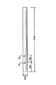
上記の繊維を昇温したマンドレル上に巻き付けた。各マンドレルは強化プラスチックにより作成されている。このマンドレルの形状および寸法を図18に示す。なお、巻き付け温度は70℃であった。
【0066】
大径が80ミルおよび小径が40ミルで4フィートの長さの卵形繊維を穴Bから約60mmの位置でマンドレルに保持してテープ留めした。2個の金属ポスト(φ2×15mm長)を穴AおよびBの中に通した。これらのマンドレルおよび繊維を70℃の一定温度の水槽中に浸漬して、1分間保持した。クランプを適当に位置決めすることにより、確実に全体の繊維に浸漬しながら張力がかかるようにして、繊維を密集したコイルに巻き上げた。さらに、巻き付け機によりマンドレルを20RPM乃至30RPMの間で回転して前立腺部分を形成した。
【0067】
上記のコイル化プロセスをテープ留め位置から開始し、コイルがポストの点Bの位置に到達した時に前立腺部分が完成した。その後、繊維をポストBから180°以上の角度まで第2のポストAに向けて引っ張ってコネクターを形成した。さらに、繊維を巻き付けてステントの先端側ループを形成する前に、繊維をマンドレルに対して垂直な位置に引き戻す。
【0068】
このようにして全体の組立体、すなわち、巻き付けたステントおよびマンドレルを水槽から取り出して、未使用の繊維部分を切断して廃棄した。このマンドレルおよびステントの組立体をアニール処理の前に少なくとも48時間真空環境内で乾燥した。
【0069】
実施例4
その後、巻き付けを終えたステントをアニール処理する。このアニール処理の前に、ポストまたはピンをマンドレルから除去した。さらに、マンドレル上に巻き付けたステントの組立体全体をアニール処理用オーブンの不活性ガス(窒素)中に吊り下げて、このオーブンを窒素により脱気した状態で、ステントを75℃で6時間アニール処理した。その後、ステントをマンドレルから取り外して、窒素ボックス内に貯蔵した。
【0070】
実施例5
実施例4において作成したステントについてインビトロ試験を行って、ステントの半径方向の応力に対する耐性を調べた。この試験により、卵形繊維により作成した単一螺旋状ステントについてのインビトロ(温度37℃でpH7.3のリン酸塩バッファー化溶液中で試験した)での圧縮破壊抵抗性試験結果を得た。
【0071】
ステントの前立腺コイル部分を全体のステントから切り取って、Instron 1122引張試験機における固定した下部プレートと移動可能な上部プレートとの間に保持した。この上部プレートを2.5mm/分の速度で移動した。半径方向の圧縮剛性およびこの2.5mm/分の速度での変形中にコイルが耐えた最大圧縮負荷を以下の表に示す。

14日間にわたって、最大負荷および剛性がインビトロ曝露の増加と共に減少した。すなわち、0.2mm(8ミル)の壁厚および実施例3に記載した組成を有する同時押出成形した卵形繊維により作成したコイルは徐々にその機械的特性を失った。しかしながら、90/10グリコリド/ラクチド・コポリマーから成る外側層および95重量%の75/25グリコリド/カプロラクトン・セグメント・ブロック・コポリマーおよび5重量%の硫酸バリウムから成る内側コアを有する丸形の同時押出成形した繊維により作成したステントはインビトロ曝露において10日で崩壊した。
【0073】
尿道内腔を開口状態に維持するために使用されるフォーリー(Foley)カテーテルのような典型的な移動可能のカテーテルに比べて、卵形繊維により作成したステントの最大負荷および剛性はインビトロ曝露における14日経過後でもホーリー・カテーテルの値よりも高い。このことは、実施例4において記載した特定の組成を有する同時押出成形した繊維により作成したステントが少なくとも14日間にわたり尿道の開通性および機能性を維持するために必要な十分に適当な機械的応答性を有していることを示している。
【0074】
実施例6
実施例5により、延長したインビトロ環境に対する曝露後の同時押出成形した繊維により作成したステントの効果を示した。さらに、インビトロ媒体内に曝露することにより、ステントを構成している繊維の内側コアおよび外側層が異なる速度でそれぞれ崩壊する。この結果において得られるステントの形態は走査電子顕微鏡による繊維断面の観察により観察できる。
【0075】
図20(a)乃至図20(c)に示す走査電子顕微鏡写真はそれぞれ14日,28日および42日インビトロ曝露を行なったステントから得た卵形繊維の断面を示している。これらの写真から、内側コアが外側層よりも速く崩壊することが分かる。すなわち、比較的速く崩壊するコアは機械的保全性を全く有しておらず、徐々に除去されている。一方、比較的遅く崩壊する外側層はさらに長い時間の経過後も小繊維の形態構造を維持している。このような異なる崩壊プロファイルおよび崩壊した各ポリマーの物理的状態の作用により、ステントの断面が中実状態から徐々に出現する中空状態の軟質構造に減少する。このような小繊維構造は、崩壊したステントの除去および/または通路が臨床的に問題になる可能性のある大きな鋭い破片に分解するのではなく、経時的に軟化する。さらに、流れの環境内において、進行的に崩壊するステントは閉鎖、痛みまたは不快を生じることなく体内腔を容易に通過できる。
【0076】
実施例7
男性の患者に適当な麻酔をかけて、従来的なレーザー治療装置による前立腺尿道の熱的な焼灼処理を行なった。この外科処理の完了後に、アプリケーター200により以下の方法で本発明のステント5を患者の尿道内および膀胱内に挿入した。すなわち、外科医はステントを所定の寸法に切除して整える。次に、このステントをアプリケーターの端部に配置する。従来的な膀胱鏡をアプリケーターの内孔部の中に挿入する。このステントおよびアプリケーターは水溶性の衣料品級の潤滑剤により潤滑化されている。基本的な膀胱鏡処理と同様に、流体溜めがアプリケーターに取り付けられている。その後、ステントを膀胱鏡による直接的な観察下で前立腺尿道の中に配置する。適正な配置後に、アプリケーターを除去して、ステントを前立腺尿道内に残す。移植後の約28日経過後に、ステントは小繊維構造に分解して、さらに軟化することにより正常な排尿において幾つかの軟質の小片の形態で尿管から排出される。
【0077】
本発明のステントは従来技術のステントに優る多くの利点を有している。これらの利点として、所定時間における剛性(内腔開通性)、崩壊軟質化機構が含まれ、この軟質化機構によりステントが容易に通過可能な1個以上の断片に軟化し、さらに、生体許容性、移動または転移を阻止する手段、X線等によるステントおよびその位置を非侵襲性的にモニターする手段等が含まれる。
【0078】
以上、本発明をその詳細な実施形態に基づいて図示し且つ説明したが、当該技術分野の熟練者であれば、これらの実施形態における形態および詳細部を本発明の趣旨および範囲に逸脱することなく多様に変更できることが理解できる。
【0079】
本発明の実施態様は以下の通りである。
(A)ステントにおいて、
複数のコイルを有する螺旋状構造から成り、当該構造が長手軸を有しており、前記コイルが一定のピッチを有しており、前記構造が長手方向に沿う内部通路を有しており、当該構造が一定の断面を有する繊維により作成されており、当該繊維が、
ラクチド、グリコリド、パラ−ジオキサノン、トリメチレン・カーボネート、カプロラクトン、およびこれらの混合物から成る群から選択されるモノマーにより形成されている生体崩壊性のポリマーにより構成されている外表面部を有する内側コアにより構成されており、当該ポリマーが第1の崩壊速度を有しており、さらに、前記繊維が、
前記内側コアの外表面部を被覆する外側層により構成されており、当該外側層が第1の生体崩壊性ポリマー成分および第2の生体崩壊性ポリマー成分の混合物により構成されていて、当該第1のポリマー成分が第1の生体崩壊性ポリマーにより構成されており、当該第1の生体崩壊性ポリマーが少なくとも約80モル%の重合化グリコリドを含有するラクチド/グリコリド・コポリマーにより構成されており、前記第2のポリマー成分が第2の生体崩壊性ポリマーにより構成されており、当該第2の生体崩壊性ポリマーが少なくとも約50モル%の重合化ラクチドを含有する高ラクチド・コポリマーにより構成されており、前記外側層が第2の崩壊速度を有しており、前記混合物が少なくとも約50重量%の第1の成分および少なくとも約5重量%の第2の成分により構成されており、
前記外側層の第2の崩壊速度が前記第1の崩壊速度よりも遅いステント。
(1)前記繊維の前記コアおよび前記外側層が同時押出成形されている実施態様(A)に記載のステント。
(2)前記内側コア用のポリマーがランダム、ブロック、およびセグメント・ブロック・シーケンス、およびこれらの組み合わせから成る群から選択されるシーケンスを含有しているポリマーにより構成されている実施態様(A)に記載のステント。
(3)前記内側コア用のポリマーが約75モル%の重合化グリコリドおよび約25モル%の重合化カプロラクトンのコポリマーにより構成されている実施態様(A)に記載のステント。
(4)前記外側層の混合物が少なくとも約50重量%の前記第1の成分および少なくとも約20重量%の前記第2の成分により構成されており、当該混合物が約38重量%乃至約89重量%の重合化グリコリドおよび残りが重合化ラクチドにより構成されている実施態様(A)に記載のステント。
(5)前記外側層の混合物の第1の成分が10/90ラクチド/グリコリド・コポリマーにより構成されており、第2の成分が85/15ラクチド/グリコリド・コポリマーにより構成されており、当該混合物が約60重量%の第1の成分および約40重量%の第2の成分により構成されており、さらに、当該混合物が約60重量%の重合化グリコリドおよび約40重量%の重合化ラクチドにより構成されている実施態様(A)に記載のステント。
【0080】
(6)前記繊維が概ね卵形の断面を有している実施態様(A)に記載のステント。
(7)前記繊維が長手方向に沿って中空の通路をさらに有している実施態様(A)に記載のステント。
(8)前記内側コアが小粒子に崩壊する実施態様(A)に記載のステント。
(9)前記外側層が小繊維形態に崩壊する実施態様(A)に記載のステント。
(10)前記繊維が概ね円形の断面を有している実施態様(A)に記載のステント。
【0081】
(11)前記螺旋状構造が2種類以上の繊維により作成されている実施態様(A)に記載のステント。
(12)前記内側コアがさらに薬剤により構成されている実施態様(A)に記載のステント。
(13)前記外側層がさらに薬剤により構成されている実施態様(A)に記載のステント。
(14)さらに、放射線不透過性化合物により構成されている実施態様(A)に記載のステント。
(15)前記外側層がコーティングである実施態様(A)に記載のステント。
【0082】
(16)前記外側層が層構造である実施態様(A)に記載のステント。
(B)生体崩壊性繊維において、
一定の断面を有する細長い部材から成り、当該部材が、
ラクチド、グリコリド、パラ−ジオキサノン、トリメチレン・カーボネート、カプロラクトン、およびこれらの混合物から成る群から選択されるモノマーにより形成されている生体崩壊性のポリマーにより構成されている外表面部を有する内側コアにより構成されており、当該内側コアが第1の崩壊速度を有しており、さらに、前記部材が、
前記内側コアの外表面部を被覆する外側層により構成されており、当該外側層が第1の生体崩壊性ポリマー成分および第2の生体崩壊性ポリマー成分の混合物により構成されていて、当該第1のポリマー成分が第1の生体崩壊性ポリマーにより構成されており、当該第1の生体崩壊性ポリマーが少なくとも約80モル%の重合化グリコリドを含有するラクチド/グリコリド・コポリマーにより構成されており、前記第2のポリマー成分が第2の生体崩壊性ポリマーにより構成されており、当該第2の生体崩壊性ポリマーが少なくとも約50モル%の重合化ラクチドを含有する高ラクチド・コポリマーにより構成されており、前記外側層が第2の崩壊速度を有しており、前記混合物が少なくとも約50重量%の第1の成分および少なくとも約5重量%の第2の成分により構成されており、
前記の第2の崩壊速度が前記第1の崩壊速度よりも遅い生体崩壊性繊維。
(17)さらに、長手方向に沿って中空の通路をさらに有している実施態様(B)に記載の繊維。
(18)前記コアおよび前記外側層が同時押出成形されている実施態様(B)に記載の繊維。
(19)前記内側コア用のポリマーがランダム、ブロック、およびセグメント・ブロック・シーケンス、およびこれらの組み合わせから成る群から選択されるシーケンスを含有しているポリマーにより構成されている実施態様(B)に記載の繊維。
(20)前記内側コア用のポリマーが約75モル%の重合化グリコリドおよび約25モル%の重合化カプロラクトンのコポリマーにより構成されている実施態様(B)に記載の繊維。
【0083】
(21)前記外側層の混合物が少なくとも約50重量%の前記第1の成分および少なくとも約20重量%の前記第2の成分により構成されており、当該混合物が約38重量%乃至約89重量%の重合化グリコリドおよび残りが重合化ラクチドにより構成されている実施態様(B)に記載の繊維。
(22)前記外側層の混合物の第1の成分が10/90ラクチド/グリコリド・コポリマーにより構成されており、第2の成分が85/15ラクチド/グリコリド・コポリマーにより構成されており、当該混合物が約60重量%の第1の成分および約40重量%の第2の成分により構成されており、さらに、当該混合物が約60重量%の重合化グリコリドおよび約40重量%の重合化ラクチドにより構成されている実施態様(B)に記載の繊維。
(23)前記内側コアが小粒子に崩壊する実施態様(B)に記載の繊維。
(24)前記外側層が小繊維形態に崩壊する実施態様(B)に記載の繊維。
(25)概ね卵形の断面を有している実施態様(B)に記載の繊維。
【0084】
(26)概ね円形の断面を有している実施態様(B)に記載の繊維。
(27)前記内側コアがさらに薬剤により構成されている実施態様(B)に記載の繊維。
(28)前記外側層がさらに薬剤により構成されている実施態様(B)に記載の繊維。
(29)さらに、放射線不透過性化合物により構成されている実施態様(B)に記載の繊維。
(30)前記外側層がコーティングである実施態様(B)に記載の繊維。
【0085】
(31)前記外側層が層構造である実施態様(B)に記載の繊維。
(32)体内腔の通路を概ね開口状態に維持する方法において、生体崩壊性のステントを備える工程から成り、当該ステントが、複数のコイルを有する螺旋状構造から成り、当該構造が長手軸および長手軸に沿う通路を有しており、前記コイルが一定のピッチを有しており、前記構造が一定の断面を有する繊維により作成されており、当該繊維が、ラクチド、グリコリド、パラ−ジオキサノン、トリメチレン・カーボネート、カプロラクトン、およびこれらの混合物から成る群から選択されるモノマーにより形成されている生体崩壊性のポリマーにより構成されている外表面部を有する内側コアにより構成されており、当該内側コアが第1の崩壊速度を有しており、さらに、前記繊維が、前記内側コアの外表面部を被覆する外側層により構成されており、当該外側層が第1の生体崩壊性ポリマー成分および第2の生体崩壊性ポリマー成分の混合物により構成されていて、当該第1のポリマー成分が第1の生体崩壊性ポリマーにより構成されており、当該第1の生体崩壊性ポリマーが少なくとも約80モル%の重合化グリコリドを含有するラクチド/グリコリド・コポリマーにより構成されており、前記第2のポリマー成分が第2の生体崩壊性ポリマーにより構成されており、当該第2の生体崩壊性ポリマーが少なくとも約50モル%の重合化ラクチドを含有する高ラクチド・コポリマーにより構成されており、前記外側層が第2の崩壊速度を有しており、前記混合物が少なくとも約50重量%の第1の成分および少なくとも約5重量%の第2の成分により構成されており、さらに、前記ステントを体内腔の中に挿入する工程から成り、前記外側層の第2の崩壊速度が前記第1の崩壊速度よりも遅く、前記外側層が軟質の小繊維形態に崩壊する方法。
(D) ステントにおいて、
長手方向の通路を有する細長い構造から成り、当該構造が、
第1の生体崩壊性ポリマー成分および第2の生体崩壊性ポリマー成分の混合物により構成されていて、当該第1のポリマー成分が第1の生体崩壊性ポリマーにより構成されており、当該第1の生体崩壊性ポリマーが少なくとも約80モル%の重合化グリコリドを含有するラクチド/グリコリド・コポリマーにより構成されており、前記第2のポリマー成分が第2の生体崩壊性ポリマーにより構成されており、当該第2の生体崩壊性ポリマーが少なくとも約50モル%の重合化ラクチドを含有する高ラクチド・コポリマーにより構成されており、前記混合物が少なくとも約50重量%の第1の成分および少なくとも約5重量%の第2の成分により構成されており、当該混合物が一定のインビボにおける崩壊速度を有しており、
前記構造が軟化により崩壊するステント。
(33)さらに、第2の崩壊速度を有する内側コアから成り、当該第2の崩壊速度が前記混合物の崩壊速度よりも速い実施態様(D)に記載のステント。
(34)管状構造から成る実施態様(33)に記載のステント。
(E) ステントにおいて、
内部通路を有する細長い構造から成り、当該構造が、
外表面部を有する内側コアにより構成されており、当該コアが第1の生体崩壊性ポリマー組成物により構成されており、当該ポリマー組成物が第1の崩壊速度を有しており、さらに、前記構造が、
前記外表面部上に配置された外側層により構成されており、当該外側層が第2の崩壊速度を有する第2の生体崩壊性ポリマー組成物により構成されており、
前記第1の崩壊速度が前記第2の崩壊速度よりも遅いステント。
(35)前記第2のポリマー組成物が第1の生体崩壊性のポリマーおよび第2の生体崩壊性のポリマーの混合物により構成されている実施態様(E)に記載のステント。
【0086】
(36)管状構造を有する実施態様(E)に記載のステント。
(37)前記ステントが螺旋状構造を有しており、前記構造が巻かれた繊維により形成されている実施態様(E)に記載のステント。
(38)前記第1のポリマー組成物がラクチド、グリコリド、パラ−ジオキサノン、トリメチレン・カーボネート、カプロラクトン、およびこれらの混合物から成る群から選択されるモノマーにより形成されているポリマーにより構成されている実施態様(E)に記載のステント。
(39)前記外側層が第1の生体崩壊性ポリマーから成る第1のポリマー成分および第2の生体崩壊性ポリマーから成る第2のポリマーの混合物により構成されており、前記第1の生体崩壊性ポリマーが少なくとも約80モル%の重合化グリコリドを含有する高グリコリド・ポリマーにより構成されており、前記第2のポリマー成分が第2の生体崩壊性ポリマーにより構成されており、当該第2の生体崩壊性ポリマーが少なくとも約50モル%の重合化ラクチドを含有する高ラクチド・コポリマーにより構成されており、前記外側層が第2の崩壊速度を有しており、前記混合物が少なくとも約50重量%の第1の成分および少なくとも約5重量%の第2の成分により構成されている実施態様(E)に記載のステント。
(40)前記混合物が少なくとも約50重量%の前記第1の成分および少なくとも約20重量%の前記第2の成分により構成されており、当該混合物が約38重量%乃至約89重量%の重合化グリコリドおよび残りが重合化ラクチドにより構成されている実施態様(39)に記載のステント。
【0087】
(41)前記外側層の混合物の第1の成分が10/90ラクチド/グリコリド・コポリマーにより構成されており、第2の成分が85/15ラクチド/グリコリド・コポリマーにより構成されており、当該混合物が約60重量%の第1の成分および約40重量%の第2の成分により構成されており、さらに、当該混合物が約60重量%の重合化グリコリドおよび約40重量%の重合化ラクチドにより構成されている実施態様(39)に記載のステント。
(42)前記内側コアのポリマーが約75モル%の重合化グリコリドおよび25モル%の重合化カプロラクトンにより構成されている実施態様(38)に記載のステント。
(43)体内腔の通路を概ね開口状態に維持する方法において、生体崩壊性のステントを備える工程から成り、当該ステントが、長手方向の通路を有しており、当該構造が、ラクチド、グリコリド、パラ−ジオキサノン、トリメチレン・カーボネート、カプロラクトン、およびこれらの混合物から成る群から選択されるモノマーにより形成されている生体崩壊性のポリマーにより構成されている外表面部を有する内側コアにより構成されており、当該ポリマーが第1の崩壊速度を有しており、さらに、前記繊維が、前記内側コアの外表面部を被覆する外側層により構成されており、当該外側層が第1の生体崩壊性ポリマー成分および第2の生体崩壊性ポリマー成分の混合物により構成されていて、当該第1のポリマー成分が第1の生体崩壊性ポリマーにより構成されており、当該第1の生体崩壊性ポリマーが少なくとも約80モル%の重合化グリコリドを含有するラクチド/グリコリド・コポリマーにより構成されており、前記第2のポリマー成分が第2の生体崩壊性ポリマーにより構成されており、当該第2の生体崩壊性ポリマーが少なくとも約50モル%の重合化ラクチドを含有する高ラクチド・コポリマーにより構成されており、前記外側層が第2の崩壊速度を有しており、前記混合物が少なくとも約50重量%の第1の成分および少なくとも約5重量%の第2の成分により構成されており、さらに、前記ステントを体内腔の中に挿入する工程から成り、前記外側層の第2の崩壊速度が前記第1の崩壊速度よりも遅く、前記外側層が軟質の小繊維形態に崩壊する方法。
(44)アニール処理されている実施態様(A)に記載のステント。
(45)アニール処理されている実施態様(B)に記載のステント。
【0088】
(C)ステントにおいて、
長手方向の通路を有する管状構造から成り、当該構造が、
ラクチド、グリコリド、パラ−ジオキサノン、トリメチレン・カーボネート、カプロラクトン、およびこれらの混合物から成る群から選択されるモノマーにより形成されている生体崩壊性のポリマーにより構成されている外表面部を有する内側コアにより構成されており、当該ポリマーが第1の崩壊速度を有しており、さらに、
前記内側コアの外表面部を被覆する外側層により構成されており、当該外側層が第1の生体崩壊性ポリマー成分および第2の生体崩壊性ポリマー成分の混合物により構成されていて、当該第1のポリマー成分が第1の生体崩壊性ポリマーにより構成されており、当該第1の生体崩壊性ポリマーが少なくとも約80モル%の重合化グリコリドを含有するラクチド/グリコリド・コポリマーにより構成されており、前記第2のポリマー成分が第2の生体崩壊性ポリマーにより構成されており、当該第2の生体崩壊性ポリマーが少なくとも約50モル%の重合化ラクチドを含有する高ラクチド・コポリマーにより構成されており、前記外側層が第2の崩壊速度を有しており、前記混合物が少なくとも約50重量%の第1の成分および少なくとも約5重量%の第2の成分により構成されており、
前記外側層の第2の崩壊速度が前記内側コアの第1の崩壊速度よりも遅いステント。
(46)織物により構成されている実施態様(C)に記載のステント。
(47)メッシュにより構成されている実施態様(C)に記載のステント。
(48)螺旋状に巻かれた繊維により構成されている実施態様(C)に記載のステント。
(49)前記外側層が内部に開口部を有する格子により構成されている実施態様(C)に記載のステント。
(F) ステントにおいて、
内部通路を有する管状構造から成り、当該構造が、
外表面部を有する内側コアにより構成されており、当該コアが第1の生体崩壊性ポリマー組成物により構成されており、当該ポリマー組成物が第1の崩壊速度を有しており、さらに、前記構造が、
前記外表面部上に配置された外側層により構成されており、当該外側層が第2の崩壊速度を有する第2の生体崩壊性ポリマー組成物により構成されており、
前記第1の崩壊速度が前記第2の崩壊速度よりも遅いステント。
(G) ステントにおいて、
長手方向の通路を有する管状構造から成り、当該構造が、
第1の生体崩壊性ポリマー成分および第2の生体崩壊性ポリマー成分の混合物により構成されていて、当該第1のポリマー成分が第1の生体崩壊性ポリマーにより構成されており、当該第1の生体崩壊性ポリマーが少なくとも約80モル%の重合化グリコリドを含有するラクチド/グリコリド・コポリマーにより構成されており、前記第2のポリマー成分が第2の生体崩壊性ポリマーにより構成されており、当該第2の生体崩壊性ポリマーが少なくとも約50モル%の重合化ラクチドを含有する高ラクチド・コポリマーにより構成されている外表面部を有する内側コアにより構成されており、前記内側コアが第1の崩壊速度を有しており、前記混合物が少なくとも約50重量%の第1の成分および少なくとも約5重量%の第2の成分により構成されており、さらに、前記構造が、
前記内側コアの外表面部を被覆する外側層により構成されており、当該外側層がラクチド、グリコリド、パラ−ジオキサノン、トリメチレン・カーボネート、カプロラクトン、およびこれらの混合物から成る群から選択されるモノマーにより形成されている生体崩壊性のポリマーにより構成されており、当該ポリマーが第2の崩壊速度を有しており、
前記外側層の第2の崩壊速度が前記内側コアの第1の崩壊速度よりも速いステント。
【0089】
【発明の効果】
従って、本発明によれば、従来に比して優れた、生体崩壊性ポリマーにより作成した新規な一時的ステントが提供できる。
【図面の簡単な説明】
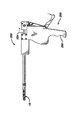
【図1】アプリケータ装置の先端部に取り付けた本発明のステント装置の好ましい実施形態の斜視図である。
【図2】アプリケータ装置にステントを装着する前の図1のステントおよびアプリケータの斜視図である。
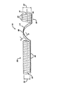
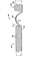
【図3】螺旋構造を有する本発明のステント装置の側面図である。
【図4】図3における線4−4に沿うステントの作成に使用した繊維の断面であり、卵形の断面を示している図である。
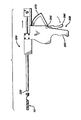
【図5】図1のステントおよびアプリケータ装置の側面図であり、この装置は使用前の待機状態で示されている図である。
【図6】図5のステントおよびアプリケータ装置の側面図であり、アプリケータ・トリガーを係合することによりステントが部分的に配備された状態におけるアプリケータに対するステントの位置を示している図である。
【図7】アプリケータ・トリガーを完全に係合することによりステントが完全に配備された状態における図6のアプリケータに対するステントの位置を示している図である。
【図8】患者の尿道および前立腺に完全に配置されて内腔部の開通性を維持している状態の本発明のステントを示している図である。
【図9】内側コアが分解した後に患者の尿道内に存在する本発明のステントを示しており、ステントが1本の細長い軟質の糸または複数の細長い軟質の糸として体外に排出されている状態を示している図である。
【図10】本発明のステントの別の実施形態を示しており、二重の繊維がステントの作成に使用されている図である。
【図11】図10における線11−11に沿うステントの断面図であり、各繊維は円形の断面を有して示されている図である。
【図12】本発明のステントの別の実施形態の斜視図であり、このステントは管状構造を有している図である。
【図13】図12における線13−13に沿うステントの断面図である。
【図14】格子状の開口部を有する環状構造の本発明のステントの別の実施形態の斜視図である。
【図15】内側コアを貫通する中空の通路を有する本発明の繊維の端面図である。
【図16】1mm(40ミル)の全体の直径および0.2mm(8ミル)の外殻層の厚さを有する同時押出成形した繊維の降伏荷重対インビトロ日数のグラフである。繊維1は90モル%のグリコリドおよび10モル%のラクチドから成る60重量%のコポリマー、および15モル%のグリコリドおよび85モル%のラクチドから成る40重量%の第2のコポリマーを含有する混合物により構成されている外側層を有している。また、繊維1の内側層はグリコリドおよびカプロラクトンから成る95重量%のコポリマーおよび5重量%の硫酸バリウムの混合物により構成されている。繊維2は90モル%のグリコリドおよび10モル%のラクチドから成るコポリマーにより構成されている外側層を有している。また、繊維2の内側層はグリコリドおよびカプロラクトンから成る95重量%のコポリマーおよび5重量%の硫酸バリウムの混合物により構成されている。
【図17】1mm(40ミル)の全体の直径および0.2mm(8ミル)の外殻層の厚さを有する同時押出成形した繊維の降伏歪対インビトロ日数のグラフである。繊維1は90モル%のグリコリドおよび10モル%のラクチドから成る60重量%のコポリマー、および15モル%のグリコリドおよび85モル%のラクチドから成る40重量%の第2のコポリマーを含有する混合物により構成されている外側層を有している。また、繊維1の内側層はグリコリドおよびカプロラクトンから成る95重量%のコポリマーおよび5重量%の硫酸バリウムの混合物により構成されている。繊維2は90モル%のグリコリドおよび10モル%のラクチドから成るコポリマーにより構成されている外側層を有している。また、繊維2の内側層はグリコリドおよびカプロラクトンから成る95重量%のコポリマーおよび5重量%の硫酸バリウムの混合物により構成されている。
【図18】実施例3において記載する特定の寸法を有するステントの概略的側面図である。
【図19】実施例3における各ステントを製造するために使用するマンドレルの概略図である。
【図20】実施例6において説明する電子顕微鏡写真を示している図である。
【符号の説明】
10 ステント
100 繊維
110 内側コア
130 外側層[0001]
BACKGROUND OF THE INVENTION
The present invention relates to a medical device, and more particularly to a stent device formed of a biodegradable polymer.
[0002]
[Prior art]
To date, methods of using stent medical devices or other types of intraluminal mechanical support devices to maintain lumens in the human body, such as conduits or vessels, have been developed and are now lumens. It has become the main treatment for stenosis or blockage. The use of stents in various surgical procedures is gaining rapid acceptance with the accumulation of experience with stent devices, and the number of surgical procedures using them is increasing as the benefits are widely recognized. For example, stents within body lumens to keep open passages such as the prostate urethra, esophagus, bile duct, intestinal tract, various coronary arteries and veins, and remote cardiac vessels such as the femoral artery It is known to use. There are two types of stents currently used: permanent stents and temporary stents. The permanent stent is configured to be maintained in the body lumen for an indeterminate amount of time. On the other hand, the temporary stent is maintained in the body lumen for a period of time and is configured to maintain the patency of the body lumen after damage to the lumen, for example, caused by a surgical procedure or injury. In general, permanent stents are configured to provide long-term support for damaged body tissue in body lumens. There are many conventional uses for such permanent stents, including cardiovascular, urinary, gastrointestinal, and gynecological applications. Such permanent stents are known to be encapsulated or covered by endothelial tissue over time, for example in pulse-related applications. Similarly, permanent stents are known to be coated with epithelium, for example, in urethral applications. Temporary stents, on the other hand, are configured to maintain luminal opening patency for a specific limited period of time and may not be incorporated into the lumen wall due to tissue ingrowth or inclusion. preferable. Preferably, the temporary stent is a predetermined clinically suitable, for example, after the damaged tissue of the lumen has been healed and the stent no longer needs to maintain the patency of the lumen. It can be removed from the body cavity after a lapse of time. For example, the temporary stent can be used as a replacement for an internally deployed catheter for use in prostate blockage or other urethral structural disease treatments. Yet another use in the body lumen of this temporary stent is as an ablation procedure with energy, such as laser or thermal ablation, or used after prostate tissue irradiation to maintain rapid postoperative urethra or other body fluids. Can be used to adjust.
[0003]
It is known in the art to make both the permanent and temporary stents described above from a variety of conventional bioacceptable metal materials. However, there are several disadvantages associated with the use of metal stents. For example, a metallic stent can be covered, encapsulated, epithelialized, or implanted by body tissue. Such stents are known to sometimes move from their initial insertion position and cause irritation to surrounding tissue in the lumen. In addition, metal materials are generally much harder and stiffer than the surrounding tissue in the lumen, making them anatomically or physiologically incompatible, damaging tissue or causing undesirable biological responses. It can happen. Although permanent metal stents are configured to be implanted for an indeterminate amount of time, it may be necessary to remove such permanent metal stents. For example, when a biological response that requires surgical intervention occurs, it is often necessary to remove such a stent by a secondary procedure. Further, when the metal stent is a temporary stent, it is necessary to remove the stent after a clinically appropriate time. That is, regardless of whether the metal stent is a permanent stent or a temporary stent, if the stent becomes encapsulated or epithelialized, surgical removal of the stent may cause unwanted pain or discomfort to the patient. Can cause additional damage to the lumen tissue. In addition to such pain and discomfort, patients must experience time-consuming and complex surgical procedures with surgical risks to remove the metal stent.
[0004]
Non-absorbable, bio-acceptable polymers or polymer compositions have particular advantages, such as reduced synthesis, but permanent stents made with such materials are also unlike metal stents as described above. Similar problems and disadvantages arise.
[0005]
In addition, it is known to use bioabsorbable and biodegradable materials when manufacturing temporary stents. Traditional bioabsorbable or biodegradable materials for making such stents are selected to eliminate the need for surgical procedures to absorb or disintegrate over time to remove the stent from the body lumen Is done. In addition to the benefits associated with eliminating the need for surgical removal of such stents, bioabsorbable and biodegradable materials are particularly competitive with most conventionally used biocompatible metal materials. Thus, it is known that there is a tendency to have excellent biotolerability. In addition, another advantage of stents made from bioabsorbable and biodegradable materials is that their mechanical properties are often associated with synthetic or hard metal stents that are often associated with vascular and lumen damage. It can be configured to eliminate or remove almost all of this.
[0006]
However, there are known disadvantages associated with the use of such bioabsorbable or biodegradable stents. That is, such inconvenience arises due to the limit of the material from which the stent is made. One of the disadvantages associated with such current stents is that the material decomposes too quickly. The stent is said to have a luminal patency, which is interrupted by normal flow, such as urination, due to improper disintegration or disintegration into large, hard debris inside the lumen of the stent, such as the urethra. The main purpose will be impaired. Alternatively, such a stent may take a long time to disassemble and stay in the target lumen for a significant amount of time after achieving its therapeutic purpose. Thus, for example, there is a long-term risk associated with these materials that form stones when implanted in a urinary environment such as the urethra.
[0007]
[Problems to be solved by the invention]
Accordingly, there is a need in the art for new temporary stents made from biodegradable polymers, which stents are intraluminal for a certain clinically appropriate time to achieve a given therapeutic purpose. After maintaining its function, it collapses without breaking down into large, hard pieces that can cause irritation, closure, pain or discomfort to the patient.
[0008]
In a preferred embodiment of the present invention, the temporary stent is easily removed from the body as very soft particles or soft fiber elements, and any irritation, closure, pain or discomfort to the patient can be eliminated or temporarily present. Even the minimum.
[0009]
[Means for Solving the Problems]
An object of the present invention is to provide a stent for insertion into a body lumen, which is made of a biodegradable polymer and can be easily discharged from a body lumen after a specific treatment time. Is possible.
[0010]
Another object of the present invention is to provide a biodegradable polymer composition that can be used to make the temporary stents described above and that disintegrates or degrades and is expelled from the body lumen. This causes little irritation, closure, pain and discomfort with little absorption in the body.
[0011]
Yet another object of the present invention is to provide a stent made of a member having an inner core having a first in vivo disintegration rate and an outer layer having a second in vivo disintegration rate.
[0012]
Thus, an implantable stent for use in a body lumen is disclosed, where the lumen exists as part of a natural anatomy or is surgically formed. The stent is an elongated hollow member, such as a tubular structure or a helical structure, and in a preferred embodiment, has a helical structure with a plurality of coils formed by wound fibers. The stent has a longitudinal axis and a passage along the longitudinal axis. Further, the coil has a constant pitch. The helical stent is formed by filaments or fibers having an inner core. Further, the inner core has an outer surface portion. If necessary, the inner core can be hollow. The filament or fiber further has an outer layer, which is a coating or coating structure on the outer surface of the inner core. Furthermore, the filament or fiber has a constant cross section. The collapse rates of the inner core and outer layer are selected so that the collapse rate of the inner core is greater than the collapse rate of the outer core. This effectively causes the inner core to collapse in vivo, losing its mechanical integrity and being almost completely removed from the lumen before the outer layer collapses while the outer layer remains. realizable. The inner core is made from monomers selected from the group consisting of lactide, glycolide, para-dioxanone, caprolactone, and trimethylene carbonate, caprolactone, mixtures thereof and copolymers thereof. An important property of the material used to make this inner core is that the material has a first decay rate and that the decay rate of the outer layer has a second decay rate. It is also expensive or big.
[0013]
The outer layer or outer structure is composed of a mixture of at least two types of polymers or copolymers. The mixture contains at least one fast disintegrating polymer and one slow disintegrating polymer. In particular, the outer or shell layer is composed of at least two polymers, the first of which is at least 80 mol% polymerized glycolide containing high glycolide-lactide / glycolide copolymer. Another of the polymers is a high lactide copolymer containing at least 50 mole percent polymerized lactide. Further, the total mixture contains at least 50% by weight high glycolide copolymer and at least 5% by weight high lactide copolymer, preferably the total mixture is from about 38% to about 97% by weight polymerization. Containing glycolide.
[0014]
Preferably, the outer or shell layer is composed of a mixture of at least two polymers, the first of which is at least 80 mol% polymerized glycolide containing high glycolide-lactide / glycolide A copolymer, another of which is a high lactide-lactide / glycolide copolymer containing at least 50 mol% polymerized lactide. In addition, each polymer component in the overall mixture (ie, a value that does not account for non-polymer components such as barium sulfate) contains at least 50% by weight high glycolide copolymer and at least 20% by weight high lactide copolymer. Preferably, the entire mixture contains from about 38% to about 89% by weight polymerized glycolide with the remainder being polymerized lactide.
[0015]
Most preferably, the outer or shell layer is composed of at least two mixtures, the first of the polymers being a high glycolide-copolymer of 10/90 lactide / glycolide copolymer, Is a high lactide-copolymer of 85/15 lactide / glycolide copolymer. In addition, each polymer component in the overall mixture (ie, a value that does not account for non-polymer components such as barium sulfate) is about 60% by weight of high glycolide copolymer (10/90 lactide / glycolide copolymer) and about 40%. % By weight high lactide copolymer (85/15 lactide / glycolide copolymer), preferably the entire mixture contains about 60% by weight polymerized glycolide and about 40% by weight polymerized lactide is doing.
[0016]
Generally, the inner core collapses upon exposure to body fluids by hydrolysis and degradation at a greater rate than the outer layer. The inner core then breaks up into small granular particles that are easily removed by body fluids. On the other hand, the outer layer collapses or erodes into a fibrillar structure. After the core collapses relatively quickly and is fully exposed to the in vivo environment, the mechanical cross section of the stent changes from a solid state to a soft structure with little loss of mechanical integrity and gradual removal. It gradually becomes hollow. Upon exposure to a hydrolyzable environment, a stent that is undergoing disintegration can be easily removed from the body lumen, minimizing the possibility of closure, pain, or discomfort. Both the inner core and outer shell layers are disintegrable, but are not bioabsorbable, so these decay products are expelled through the body lumen. In one example of an embodiment of the present invention, the device is soft and pliable in an in vivo environment so that it can be easily ejected from the lumen in almost a single piece. In another embodiment, the device not only becomes soft and flexible, but also breaks down into smaller, separate, non-occlusive debris that can pass through the lumen.
[0017]
Yet another aspect of the present invention is a stent as described above made from fibers that are radiopaque.
[0018]
Yet another aspect of the present invention is a stent as described above having only an outer layer that does not have an inner core.
[0019]
Yet another aspect of the present invention is a fiber as described above for making a stent having a helical structure.
[0020]
Yet another aspect of the present invention is a method of using a stent of the present invention in a surgical procedure to maintain body lumen patency. That is, first, the stent of the present invention is provided. The stent is an elongated hollow member and, in a preferred embodiment, has a helical structure with a plurality of coils. This member has a longitudinal axis. Furthermore, the coil has a constant pitch. This structure is made of filaments or fibers with an inner core. The inner core has an outer surface portion. If necessary, the inner core is hollow. In addition, the filament or fiber has an outer layer that covers almost the entire outer surface of the inner core. The filament or fiber has a constant cross section. The collapse rate of the inner core and outer layer is, in a preferred embodiment, such that the collapse rate of the inner core is greater than the outer collapse rate, the inner core collapses in vivo, and its mechanical integrity is lost. It is chosen so that it is effectively removed from the lumen before the layer collapses and disappears. In general, the inner core collapses upon exposure to body fluids by hydrolysis or degradation at a greater rate than the outer layer, and the outer layer collapses or erodes to a soft, fibrous form. By inserting the stent into the body cavity of the patient, the patency of the body cavity is maintained for a certain range of time. That is, the stent is maintained in the body lumen only for a certain period of time, thereby effectively maintaining the body lumen in an open state, and the inner core effectively collapsing so that the softened outer core is discharged from the lumen. become able to.
[0021]
Yet another aspect of the present invention is the stent and fiber described above, wherein a relatively slow disintegrating polymer mixture is used for the core and a relatively fast disintegrating polymer material is used as the outer layer or outer structural portion. ing.
[0022]
DETAILED DESCRIPTION OF THE INVENTION
These and other aspects of the invention will become more apparent from the following description, examples and accompanying drawings.
[0023]
1 to 9 show a preferred embodiment of the present invention. As shown in FIG. 3, the
[0024]
Another embodiment of the stent of the present invention is shown in FIG. The
[0025]
Although not particularly preferred, the stent of the present invention can also be made of fibers without an inner core. That is, such fibers have only a collapsible outer layer without an inner core. Such fibers can be solid or can have hollow passages. Similarly, if a tubular structure is desired and an inner core need not be provided, a structure with a hollow passage can be made with just the polymer composition used for the outer layer.
[0026]
Preferably, the
[0027]
The stent of the present invention can have a tubular member, a lattice-like member and the like in addition to the wound fiber structure. Examples of such tubular stents are shown in FIGS. A person skilled in the art can understand that the structure as described above can be formed of a woven fabric, a mesh, a flat material that can be wound into a certain shape, or the like. Such a structure, like the fibers and helical stents according to the invention, can also be made simply by a mixed material having an inner core and an outer layer or used to make parts of the outer layer. is there.
[0028]
Furthermore, it should be understood that other embodiments of the stents and fibers of the present invention may have a relatively slow disintegrating polymer component as the inner core and a relatively fast disintegrating polymer component as the outer layer. Such a relatively fast disintegrating outer layer falls off or collapses over time leaving a softened inner core, after which the inner core is drained or removed from the lumen. These polymer components are the same as in another embodiment, i.e., relatively fast disintegrating and relatively slow disintegrating components.
[0029]
Preferably, the fibers of the present invention are made to have an inner core composed of a first disintegrating polymer composition and an outer layer composed of a second disintegrating polymer composition. The inner core polymer material is selected such that when exposed to body fluids over time, the inner core collapses upon hydrolysis and its mechanical integrity disappears at a greater rate than the outer layer. Preferably, the inner core breaks down into small granular particles that are easily removed by body fluids. Also, the polymeric material of the outer layer or coating is preferably selected to have a relatively slow hydrolysis rate so that it disintegrates or erodes into a fibrillar form structure after exposure to body fluids in vivo. Thus, when the outer layer is in the form of fibrils, the collapsed product of the inner core that disintegrates relatively quickly is easily dispersed.
[0030]
The fibril form of the outer layer is the result of the polymer blend composition and the process conditions for making it. This fibrillar form softens the outer layer over time without breaking down into large pieces that can close or occlude in the lumen. In different embodiments of the present invention, preferably the fibers have a solid or hollow cross section with an inner core and an outer layer made of a polymer mixture.
[0031]
The relatively slow disintegrating outer layer is in the form of fibrils and the relatively fast disintegrating core is gradually removed, losing firm mechanical integrity. These different disintegrating effects and the physical state of the collapsed polymer change the stent cross-section from its solid state to a soft structure that gradually becomes hollow. In addition, the fibrillar structure softens over time without breaking into large, sharp pieces that can cause the removal and passage of clinically problematic collapsed stents. Furthermore, in a flow environment, a progressively collapsing stent can easily pass through a body lumen without causing closure, pain or discomfort. Both the inner core and outer shell layers are not absorbed by the lumen wall as their decay products pass through the body lumen.
[0032]
The stent must be configured to withstand the radial stress and perform the function of maintaining the lumen passageway open. The mechanical properties of the stent of the present invention that withstand radial stress when such a stent is present in a body lumen are primarily imparted by the biodegradable material in the outer shell layer. The strength, rigidity, and thickness of the material in the outer shell layer are values that can sufficiently withstand the loads required to maintain the stent function. That is, when the inner core collapses and splits, an outer shell wall of sufficient thickness composed of a suitably selected biodegradable material is necessary to maintain lumen patency. It can effectively withstand the required load for the time. Therefore, the tubular outer shell layer portion can be configured to satisfy the mechanical conditions necessary to maintain the patency or open state of the body lumen for a certain treatment time. In addition to being configured to disintegrate into small granular fragments, the inner core has another functional need, such as a radiopaque marker carrier or a possible processing aid during stent manufacture. Can be filled with another conventional material satisfying For example, such filled cores can reduce fiber “flattening” that can occur when winding hollow stents at high temperatures.
[0033]
By appropriately selecting the disintegration rate, the inner core splits into small pieces in vivo, while some or all of the outer layer remains unchanged to yield specific “soft” fragments or filaments. . That is, after the inner core is collapsed by body fluid and effectively removed from the stent structure, the remaining outer layer collapses to form a soft, pliable, fibrillar filament that is then shaped. Remains unchanged or collapses into several parts. Such remaining soft filaments, or debris thereof, are easily ejected from the lumen.
[0034]
As already mentioned, although not preferred, it is possible to produce the stent according to the invention with fibers consisting only of the material of the outer layer without an inner core. Such fibers may be either hollow or solid. Similarly, the tubular stent of the present invention can be manufactured without an inner core. When manufacturing such an embodiment, it is not necessary to employ coextrusion molding. Otherwise, the requirements for the mechanical strength and disintegration rate of the stent are similar.
[0035]
Useful polymeric materials for the stents and fibers of the present invention include biodegradable polymers disclosed in US Pat. No. 4,889,119, incorporated herein by reference. In embodiments of the invention that utilize an inner core, the inner core is composed of one or more polymers that have a biodegradation rate that is higher than the biodegradation rate of the outer or outer layer. The polymers used to make the inner core include polymers that hydrolyze, disintegrate or degrade sufficiently effectively at a relatively high rate compared to the material of the outer layer. Preferably, these polymers include polymers made with monomers of lactide, glycolide, para-dioxanone, trimethylene carbonate and caprolactone. As used herein, the term “caprolactone” means epsilon-caprolactone. Each of the above monomers can be used to make a copolymer having a random, block or segment block sequence, or a combination thereof. In particular, glycolide and caprolactone segment block copolymers containing about 75 mole percent polymerized glycolide and about 25 mole percent polymerized caprolactone are useful. Combinations of the above copolymers can also be used.
[0036]
On the other hand, the polymeric material used for the outer layer of the stent of the present invention hydrolyzes, disintegrates and degrades sufficiently effectively at a relatively slow rate, preferably a polymer that forms a fibrillar structure upon in vivo exposure. Selected from. Preferably, polymers that can be used to form the outer layer include polylactide, polyglycolide, polypararadioxane, and polycaprolactone and mixtures thereof, and copolymers and equivalents thereof. In particular, it is preferred to use a mixture of at least two polymers or copolymers in the outer layer. The mixture may also contain at least one relatively fast disintegrating polymer and one relatively slow disintegrating polymer. Although not indispensable, there is a certain compatibility between the two types of polymers in the outer layer, but it is preferable that they are not completely mixed. Furthermore, in the case of the outer layer, a mixture of glycolide copolymer containing at least 80 mol% polymerized glycolide is used, and another of the polymers is a polylactide copolymer containing at least 50 mol% polymerized lactide. It is particularly preferred. The mixture as a whole contains at least 50% by weight glycolide copolymer and at least 5% by weight lactide copolymer, from about 38% to about 97% by weight polymerized glycolide and the remainder being polymerized lactide Is preferred.
[0037]
Fibers useful in making the stent of the present invention comprise an inner core composed of a first biodegradable material having a first disintegration rate and a second biodegradable material having a second disintegration rate. It has an outer layer and can be manufactured by a variety of conventional techniques including conventional extrusion processes. For example, a fiber is formed by feeding a first polymer composition to a first pump of a conventional coextrusion device and a second polymer composition to a second pump of a conventional coextrusion device. can do. The first pump then delivers the first polymer composition into the interior of the coextrusion die and the second pump delivers the second polymer composition to a concentric portion outside the coextrusion die. Thus, a fiber having an inner core and an outer layer is formed. If desired, the fibers of the present invention can be made by other conventional processes including melt coating, solution coating or powder coating followed by diffusion treatment of the coating agent by melt processing. For example, when utilizing such a coating process, the inner core can be a mono-filament extruded material and can be made with a multi-filament blade. Thereafter, the outer layer can be formed on the upper surface of the inner core by melt coating or solution coating by passing the inner core through a bath or coating roller, spraying and / or using a die. If it is desired to produce the stent of the present invention as a single tubular structure rather than a rolled fiber structure, it is sufficiently effective to select a coextrusion die using a coextrusion process. Any suitable diameter tube having a hollow inner core with a sufficient thickness and an outer layer with a sufficiently effective thickness can be formed. Furthermore, fibers useful in making the stent of the present invention can be made to have a hollow passage through the core, if desired.
[0038]
It is important to recognize that high lactide polymers such as 95/5 poly (lactide-co-glycolide) can be used to provide excellent initial mechanical properties and good maintainability of these properties over time It is. On the other hand, the significant disadvantages of using materials (such as conventional absorbable synthetic homo- or copolymers) above to form temporary stents have begun to collapse devices made with these materials Sometimes these devices usually cause mechanical failure due to their extreme failure mechanisms.
[0039]
First, cracks occur and spread very quickly, causing the article to “bisect” and cause the “radical break” described above. While these rapidly spreading cracks begin to develop, the material remains extremely hard. Therefore, as the article collapses and initially begins to break down into large hard pieces, these continue to break down into smaller pieces. In this case, unless constrained, it is natural that these large debris move and cause serious anatomical and / or biological injury before collapsing into harmless, finely divided particles. It is done. In particular, in the case of temporary stents made with conventional resorbable synthetic (homo- or) copolymers as described above, these debris can close or occlude the lumen that the stent intended to open.
[0040]
Therefore, by copolymerization of lactide and glycolide (either random, segmental or block modification from polyglycolide homopolymer to polylactide homopolymer), appropriate initial mechanical properties, suitably good mechanical properties over time However, it is not impossible but extremely difficult to maintain a softening and alteration mechanism.
[0041]
The inventor is able to create a biodegradable temporary stent using the mixture described in US Pat. No. 4,889,119 for producing plastic surgical fasteners that can be absorbed by an injection molding process. It was discovered by chance that it can be used very effectively in the production of fibers. Furthermore, the inventor has shown that a fiber comprising the mixture described in the above patent in the form of a hollow fiber structure, in particular in the form of a fiber having a hollow core made of a second fastener-disintegrating material, is a highly preferred embodiment of the invention. It was found that can be configured.
[0042]
The inventor does not wish to discuss scientific theory or principles in particular, but the inventor believes that the above mixed composition produces morphological effects due to the action of high lactide polymers as crack restraints. Yes. Therefore, cracks that have started to occur are restrained without spreading very quickly. These cracks begin to develop with the material being very hard, but the article does not "divide into two" because the cracks are limited from spreading quickly. Over time, the article will generate other small cracks, but the high lactide mixing component acting as a “crack constraining” microphase will prevent splitting through the article completely through the crack. In addition, this high lactide blending component reinforces the article until it cracks and harmlessly decomposes without causing numerous cracks and large potentially occlusive or occlusive debris as in the prior art. To help.
[0043]
In another embodiment of the invention, the polymers and mixtures used to form the above compositions can be utilized as drug delivery substrates. To form such a matrix, the above polymers are mixed with a therapeutic agent. The range of different therapeutic agents that can be used with the polymers of the present invention is extremely wide. In general, therapeutic agents that can be administered with the pharmaceutical composition of the present invention include anti-infectives such as antibiotics and antiviral agents, analgesics and mixtures of analgesics, anti-inflammatory agents, hormones such as steroids, bone regenerative growth Factors and include, but are not limited to, naturally derived or genetically engineered proteins, polysaccharides, glycoproteins, or lipoproteins.
[0044]
The matrix formulation can be formulated by mixing one or more therapeutic agents with the polymer. The therapeutic agent can be present as a liquid, a finely divided solid, or any other suitable physical form. In general, but not as a necessary choice, the substrate described above may contain one or more additives such as diluents, carriers, excipients, stabilizers and the like.
[0045]
The amount of the therapeutic agent will depend on the particular drug used and the medical condition being treated. Generally, the amount of drug is from about 0.001% to about 70%, more typically from about 0.001% to about 50%, most typically about 0.001% by weight of the substrate. % To about 20% by weight. Furthermore, the amount and type of polymer mixed into the drug delivery matrix will depend on the desired release profile and the amount of drug used.
[0046]
When in contact with body fluids, the polymer gradually disintegrates (mainly due to hydrolysis), which is accompanied by the release of the dispersed drug in a certain sustained or extended time. This ensures a sustained supply (eg, 1 hour to 5000 hours, preferably 2 hours to 800 hours) of an effective amount (eg, 0.0001 mg / kg / hour to 10 mg / kg / hour). Yes. This dosage form is a form that can be administered according to the necessity to be determined by the subject to be treated, the degree of pain, the adjustment of the prescribing physician, and the like. By following such a process, those skilled in the art can prepare various formulations.
[0047]
The
[0048]
The stent of the present invention can be used in the following manner in the urethral stent placement process as shown in FIGS. 1, 2, 5, 6, 7 and 8. First, the
[0049]
The distal end of the stent and
[0050]
The following examples illustrate, but do not limit, the principles and practice of the present invention.
[0051]
Example 1
The material mixture used to produce the inner core and outer layers of fibers useful in forming the stents of the present invention by winding was created. Example 2 shows how the material is used in this fiber blend.
[0052]
The outer shell layer contains 60 wt% first random copolymer containing 90 mol% polymerized glycolide and 10 mol% polymerized lactide and 85 mol% polymerized lactide and 15 mol% polymerized glycolide. Of 40% by weight of a second copolymer. The first copolymer containing 90 mole% polymerized glycolide and 10 mole% polymerized lactide, i.e. 90/10 glycolide / lactide copolymer, has an intrinsic viscosity of 0.1 g / dL and 25 ° C. 1.4 dL / g in HFIP (hexafluoroisopropanol) at temperature. Also, the intrinsic viscosity of the second copolymer containing 85 mole% polymerized lactide and 15 mole% polymerized glycolide, i.e., 85/15 lactide / glycolide copolymer, has a concentration of 0.1 g / dL and 25 2.1 dL / g in chloroform at a temperature of ° C. These two copolymers were mixed at a 60/40 weight ratio and then melt mixed and pelletized with a 40: 1 L: D ratio, medium shear screw configuration and appropriate ventilated 18 mm twin screw extruder. did. The temperature profile from the rear region to the die flange was 130 ° C, 205 ° C, 205 ° C, 210 ° C, 210 ° C, 210 ° C and 205 ° C. The die was a 2.5 mm diameter single orifice rod die with a die temperature of 200 ° C. The processed product extruded by the twin screw was rapidly cooled in a water bath and pelletized. The intrinsic viscosity of the first mixture containing polymerized glycolide and polymerized lactide thus obtained was 1.6 dL / g in hexafluoroisopropanol at a concentration of 0.1 g / dL and a temperature of 25 ° C. It was.
[0053]
On the other hand, the inner core is composed of a mixture containing 95% by weight segmented block copolymer consisting of 75% by mole polymerized glycolide and 25% by weight polymerized caprolactone and 5% by weight barium sulfate. The segment block copolymer containing glycolide and caprolactone, ie 75/25 glycolide / caprolactone, has an intrinsic viscosity of 1.5 dL / g in hexafluoroisopropanol at a concentration of 0.1 g / dL and a temperature of 25 ° C. there were. Mixing barium sulfate makes the fiber radiopaque. The above two components are premixed at the required 95/5 weight ratio and then melt mixed to obtain an 18
[0054]
Example 2
A method for producing a coextruded fiber having a round cross-sectional shape is as follows. The materials used for the inner core and outer layer are those described in Example 1 above. That is, the outer layer was made of 60 wt% 90/10 glycolide / lactide copolymer and 40 wt% 85/15 lactide / glycolide copolymer. The inner layer was made with 95 wt% 75/25 glycolide / caprolactone segment block copolymer and 5 wt% barium sulfate. In addition, in vitro fiber tensile tests were performed and compared against coextruded fibers containing only 90/10 glycolide / lactide copolymer.
[0055]
The above fibers were coextruded by two single screw extruders. These screws had a compression ratio of 3: 1 and an L / D ratio of 25: 1. A 1 inch horizontal extruder was used for the outer layer and a 5/8 inch vertical extruder was used for the inner core. Two streams of material were fed into a single orifice die using a concentric two-layer feed-block, from which the extrudate was fed into water and cooled. The excess surface moisture was then removed with an air jet and the fiber was cut to the desired length of about 4 feet using an air cutter. The fiber diameter (large diameter and small diameter) on the line was measured using a laser micrometer, and the wall thickness of the inner core and the outer layer was confirmed with a microscope.
[0056]
The temperature profile of the material in the outer layer from the rear barrel region to the die flange was 185 ° C, 210 ° C, 222 ° C, 215 ° C and 215 ° C. The material in this outer layer was a mixture of 60% by weight 90/10 glycolide / lactide copolymer and 40% by weight 85/15 lactide / glycolide copolymer. The temperature profile of the material in the inner core from the rear barrel region to the die flange was 215 ° C, 224 ° C, 224 ° C and 230 ° C. The material in this inner core was a mixture of 95% by weight 75/25 glycolide / caprolactone segment block copolymer and 5% by weight barium sulfate. In this case, a single hole die having a circular cross section set at a temperature of 213 ° C. was used.
[0057]
The yield load and yield strain in the in vitro environment of the coextruded round fiber made by the above method was compared with the values in the coextruded round fiber with different materials in the outer layer in FIGS. . Both fibers were both 1 mm (40 mils) in diameter and the outer layer thickness was 0.2 mm (8 mils). Also, the inner core of both fibers is the same and is a mixture of 95% by weight 75/25 glycolide / caprolactone segment block copolymer and 5% by weight barium sulfate. On the other hand, the outer layer of the first round fiber was formed by a mixture containing 60% by weight of 90/10 glycolide / lactide copolymer and 40% by weight of 85/15 lactide / glycolide copolymer. In addition, the outer layer of the second round fiber was made with a 90/10 glycolide / lactide copolymer. In addition, both of these fibers were annealed at 75 ° C. for 6 hours.
[0058]
Next, a tensile test was performed on each fiber by Instron 4500, and each fiber sample was pulled at a rate of 30.5 mm / min. The sample length in this case was 2.54 mm. The yield load and yield strain were measured. For this in vitro test, each of the above samples was kept in a phosphate buffer bath at pH 7.27 at a temperature of 37 ° C. Thereafter, these samples were taken out of the water tank at regular intervals, and their yield load and yield strain were examined.
[0059]
A high lactide copolymer, ie 85/15 lactide / glycolide, due to the complete disappearance of its yield load within 10 days in the case of the second round fiber (no mixed material in the outer layer) The significance in the first round fiber that the copolymer is added to the high glycolide copolymer, ie 90/10 glycolide / lactide copolymer, becomes clear. In addition, the yield strain in the case of the first fiber containing the mixed material in the outer layer temporarily decreases, but recovers due to the presence of the high lactide component. Thus, the high lactide component is the material of the outer layer of the first round fiber in a relatively long in vitro exposure compared to the outer layer in the second round coextruded fiber containing only the high glycolide copolymer. It is thought to impart toughness to the steel.
[0060]
Example 3
The process used to convert a fiber having an oval or elliptical cross section into a stent will now be described in this example. A stent having a single helical structure was formed from a single oval fiber. In this case, each co-extruded fiber containing each material prepared in Example 1 was considered as the outer layer and inner core of this oval fiber.
[0061]
First, a method for producing an egg-shaped coextruded fiber will be described. The materials used for the outer layer and inner core were those described in Example 1. The outer layer was made with a mixture of 60% by weight 90/10 glycolide / lactide copolymer and 40% by weight 85/15 lactide / glycolide copolymer. On the other hand, the inner core was made of a mixture of 95% by weight 75/25 glycolide / caprolactone segment block copolymer and 5% by weight barium sulfate.
[0062]
Next, the egg-shaped fiber was coextruded by two single screw extruders. Both screws had a compression ratio of 3: 1 and an L / D ratio of 25: 1. A 1 inch horizontal extruder was used for the outer layer and a 5/8 inch vertical extruder was used for the inner core. Two streams of material were fed into a single orifice die using a concentric two-layer feed-block, from which the extrudate was fed into water and cooled. The excess surface moisture was then removed with an air jet and the fiber was cut to the desired length of about 4 feet using an air cutter. The fiber diameter (large diameter and small diameter) on the line was measured using a laser micrometer, and the wall thickness of the inner core and the outer layer was confirmed with a microscope.
[0063]
The temperature profile of the material in the outer layer from the rear barrel region to the die flange was 185 ° C, 210 ° C, 222 ° C, 215 ° C and 215 ° C. The material in this outer layer was a mixture of 60% by weight 90/10 glycolide / lactide copolymer and 40% by weight 85/15 lactide / glycolide copolymer. The temperature profile of the material in the inner core from the rear barrel region to the die flange was 215 ° C, 224 ° C, 224 ° C and 230 ° C. The material in this inner core was a mixture of 95% by weight 75/25 glycolide / caprolactone segment block copolymer and 5% by weight barium sulfate. In this case, a single hole die with an oval cross section set at a temperature of 213 ° C. was used.
[0064]
The dimensions of the co-extruded oval fibers were 1 mm (40 mils) small diameter and 2 mm (80 mils) large diameter, and the outer layer wall thickness was 0.2 mm (8 mils).
[0065]
The above fiber was wound on a mandrel whose temperature was increased. Each mandrel is made of reinforced plastic. The shape and dimensions of this mandrel are shown in FIG. The winding temperature was 70 ° C.
[0066]
An oval fiber having a major diameter of 80 mils and a minor diameter of 40 mils and a length of 4 feet was held on a mandrel at about 60 mm from hole B and taped. Two metal posts (φ2 × 15 mm long) were passed through holes A and B. These mandrels and fibers were immersed in a constant temperature water bath at 70 ° C. and held for 1 minute. By properly positioning the clamps, the fibers were wound up in a dense coil, ensuring tension while immersing in the entire fiber. In addition, the mandrel was rotated between 20 RPM and 30 RPM with a wrapping machine to form the prostate portion.
[0067]
The coiling process described above was started from the taped position and the prostate portion was completed when the coil reached the position of point B on the post. Thereafter, the fiber was pulled toward the second post A from the post B to an angle of 180 ° or more to form a connector. Further, the fiber is pulled back to a position perpendicular to the mandrel before the fiber is wrapped to form the distal loop of the stent.
[0068]
The entire assembly, that is, the wound stent and mandrel, was removed from the water bath and the unused fiber portion was cut and discarded. The mandrel and stent assembly was dried in a vacuum environment for at least 48 hours prior to annealing.
[0069]
Example 4
Thereafter, the wound stent is annealed. Prior to this annealing treatment, the post or pin was removed from the mandrel. Further, the entire stent assembly wound on the mandrel is suspended in an inert gas (nitrogen) in an annealing oven, and the stent is annealed at 75 ° C. for 6 hours while the oven is deaerated with nitrogen. did. The stent was then removed from the mandrel and stored in a nitrogen box.
[0070]
Example 5
The stent produced in Example 4 was tested in vitro to determine its resistance to radial stress. This test provided in vitro compression fracture resistance test results for a single helical stent made of oval fibers (tested in a phosphate buffered solution at pH 7.3 at a temperature of 37 ° C.).
[0071]
The prostate coil portion of the stent was cut from the entire stent and held between a fixed lower plate and a movable upper plate in an Instron 1122 tensile tester. The upper plate was moved at a speed of 2.5 mm / min. The following table shows the radial compression stiffness and the maximum compression load that the coil withstood during deformation at this 2.5 mm / min rate.
Over 14 days, maximum load and stiffness decreased with increasing in vitro exposure. That is, a coil made of co-extruded oval fibers having a wall thickness of 0.2 mm (8 mils) and the composition described in Example 3 gradually lost its mechanical properties. However, a round co-extrusion with an outer layer consisting of 90/10 glycolide / lactide copolymer and an inner core consisting of 95% by weight 75/25 glycolide / caprolactone segment block copolymer and 5% by weight barium sulfate. The stent made with the finished fibers disintegrated in 10 days upon in vitro exposure.
[0073]
Compared to typical movable catheters such as Foley catheters used to keep the urethral lumen open, the maximum load and stiffness of a stent made with oval fibers is 14 in in vitro exposure. It is higher than the value of the Holy catheter even after the passage of days. This is a sufficiently adequate mechanical response that is necessary for a stent made of coextruded fibers having the specific composition described in Example 4 to maintain urethral patency and functionality for at least 14 days. It shows that it has sex.
[0074]
Example 6
Example 5 demonstrated the effect of a stent made with co-extruded fibers after exposure to an extended in vitro environment. Furthermore, exposure to in vitro media causes the inner core and outer layers of fibers making up the stent to collapse at different rates, respectively. The form of the stent obtained in this result can be observed by observing the fiber cross section with a scanning electron microscope.
[0075]
The scanning electron micrographs shown in FIGS. 20 (a) to 20 (c) show the cross-sections of oval fibers obtained from stents subjected to in vitro exposure for 14 days, 28 days and 42 days, respectively. From these photographs it can be seen that the inner core collapses faster than the outer layer. That is, cores that disintegrate relatively quickly do not have any mechanical integrity and are gradually removed. On the other hand, the outer layer that disintegrates relatively slowly maintains the fibril structure even after a longer period of time. Such a different collapse profile and the physical state effect of each collapsed polymer reduces the cross-section of the stent from a solid state to a hollow, soft structure that gradually emerges. Such a fibrillar structure softens over time, rather than breaking into large sharp debris where the removal and / or passage of a collapsed stent can be clinically problematic. Furthermore, in a flow environment, a progressively disintegrating stent can easily pass through a body lumen without causing closure, pain or discomfort.
[0076]
Example 7
A male patient was appropriately anesthetized and a thermal ablation of the prostate urethra was performed using a conventional laser therapy device. After completion of this surgical procedure, the stent 5 of the present invention was inserted into the urethra and bladder of the patient by the
[0077]
The stent of the present invention has many advantages over prior art stents. These advantages include stiffness at a given time (lumen patency), collapse softening mechanism, which softens the stent into one or more pieces that can be easily passed through, and is biocompatible. , Means for preventing migration or metastasis, stents by X-rays and the like, and means for non-invasively monitoring the position thereof.
[0078]
Although the present invention has been illustrated and described based on the detailed embodiments, those skilled in the art will depart from the spirit and scope of the present invention in the form and details of these embodiments. It can be understood that various changes can be made.
[0079]
Embodiments of the present invention are as follows.
(A) In the stent,
A spiral structure having a plurality of coils, the structure has a longitudinal axis, the coils have a constant pitch, the structure has an internal passage along the longitudinal direction, The structure is made of fibers having a constant cross section, and the fibers are
Consists of an inner core having an outer surface portion composed of a biodegradable polymer formed by a monomer selected from the group consisting of lactide, glycolide, para-dioxanone, trimethylene carbonate, caprolactone, and mixtures thereof The polymer has a first disintegration rate, and the fiber further comprises:
An outer layer covering the outer surface portion of the inner core, the outer layer being composed of a mixture of a first biodegradable polymer component and a second biodegradable polymer component, Wherein the polymer component is composed of a first biodegradable polymer, the first biodegradable polymer is composed of a lactide / glycolide copolymer containing at least about 80 mol% polymerized glycolide, The second polymer component is composed of a second biodegradable polymer, the second biodegradable polymer is composed of a high lactide copolymer containing at least about 50 mole percent polymerized lactide; The outer layer has a second disintegration rate, and the mixture comprises at least about 50% by weight of the first component and at least about 5; It is constituted by a second component in an amount%
A stent wherein the second disintegration rate of the outer layer is slower than the first disintegration rate.
(1) The core and the outer layer of the fiber are coextruded.Embodiment (A)The stent according to 1.
(2) The polymer for the inner core is composed of a polymer containing a sequence selected from the group consisting of random, block, and segment block sequences, and combinations thereof.Embodiment (A)The stent according to 1.
(3) The polymer for the inner core is composed of a copolymer of about 75 mol% polymerized glycolide and about 25 mol% polymerized caprolactone.Embodiment (A)The stent according to 1.
(4) The outer layer mixture is comprised of at least about 50% by weight of the first component and at least about 20% by weight of the second component, the mixture being from about 38% to about 89% by weight. The polymerized glycolide and the remainder are composed of polymerized lactideEmbodiment (A)The stent according to 1.
(5) The first component of the outer layer mixture is composed of 10/90 lactide / glycolide copolymer, the second component is composed of 85/15 lactide / glycolide copolymer, and the mixture is About 60% by weight of the first component and about 40% by weight of the second component, and the mixture further comprises about 60% by weight of polymerized glycolide and about 40% by weight of polymerized lactide. ingEmbodiment (A)The stent according to 1.
[0080]
(6) The fiber has a generally oval cross section.Embodiment (A)The stent according to 1.
(7) The fiber further has a hollow passage along the longitudinal direction.Embodiment (A)The stent according to 1.
(8) The inner core collapses into small particlesEmbodiment (A)The stent according to 1.
(9) The outer layer collapses into a fibril formEmbodiment (A)The stent according to 1.
(10) The fiber has a substantially circular cross section.Embodiment (A)The stent according to 1.
[0081]
(11) The spiral structure is made of two or more types of fibersEmbodiment (A)The stent according to 1.
(12) The inner core is further composed of a drugEmbodiment (A)The stent according to 1.
(13) The outer layer is further composed of a drugEmbodiment (A)The stent according to 1.
(14) Furthermore, it is comprised by the radiopaque compound.Embodiment (A)The stent according to 1.
(15) The outer layer is a coatingEmbodiment (A)The stent according to 1.
[0082]
(16) The outer layer has a layer structure.Embodiment (A)The stent according to 1.
(B) In biodegradable fibers,
Consisting of an elongated member having a constant cross-section,
Consists of an inner core having an outer surface portion composed of a biodegradable polymer formed by a monomer selected from the group consisting of lactide, glycolide, para-dioxanone, trimethylene carbonate, caprolactone, and mixtures thereof The inner core has a first decay rate, and the member further comprises:
An outer layer covering the outer surface portion of the inner core, the outer layer being composed of a mixture of a first biodegradable polymer component and a second biodegradable polymer component, Wherein the polymer component is composed of a first biodegradable polymer, the first biodegradable polymer is composed of a lactide / glycolide copolymer containing at least about 80 mol% polymerized glycolide, The second polymer component is composed of a second biodegradable polymer, the second biodegradable polymer is composed of a high lactide copolymer containing at least about 50 mole percent polymerized lactide; The outer layer has a second disintegration rate, and the mixture comprises at least about 50% by weight of the first component and at least about 5; It is constituted by a second component in an amount%
The biodegradable fiber, wherein the second disintegration rate is slower than the first disintegration rate.
(17) Further, it further has a hollow passage along the longitudinal direction.Embodiment (B)Fiber as described in.
(18) The core and the outer layer are coextruded.Embodiment (B)Fiber as described in.
(19) The polymer for the inner core is composed of a polymer containing a sequence selected from the group consisting of random, block, and segment block sequences, and combinations thereof.Embodiment (B)Fiber as described in.
(20) The polymer for the inner core is composed of a copolymer of about 75 mol% polymerized glycolide and about 25 mol% polymerized caprolactone.Embodiment (B)Fiber as described in.
[0083]
(21) The outer layer mixture comprises at least about 50 wt% of the first component and at least about 20 wt% of the second component, the mixture being from about 38 wt% to about 89 wt% The polymerized glycolide and the remainder are composed of polymerized lactideEmbodiment (B)Fiber as described in.
(22) The first component of the outer layer mixture is composed of 10/90 lactide / glycolide copolymer, the second component is composed of 85/15 lactide / glycolide copolymer, About 60% by weight of the first component and about 40% by weight of the second component, and the mixture further comprises about 60% by weight of polymerized glycolide and about 40% by weight of polymerized lactide. ingEmbodiment (B)Fiber as described in.
(23) The inner core collapses into small particlesEmbodiment (B)Fiber as described in.
(24) The outer layer collapses into a fibril formEmbodiment (B)Fiber as described in.
(25) It has a generally oval cross section.Embodiment (B)Fiber as described in.
[0084]
(26) It has a substantially circular cross section.Embodiment (B)Fiber described in.
(27) The inner core is further composed of a drugEmbodiment (B)Fiber described in.
(28) The outer layer is further composed of a drug.Embodiment (B)Fiber described in.
(29) Further, it is composed of a radiopaque compound.Embodiment (B)Fiber described in.
(30) The outer layer is a coatingEmbodiment (B)Fiber described in.
[0085]
(31) The outer layer has a layer structure.Embodiment (B)Fiber described in.
(32) A method for maintaining a passage of a body lumen in a generally open state, comprising a step of providing a biodegradable stent, the stent comprising a spiral structure having a plurality of coils, and the structure comprising a longitudinal axis and a longitudinal axis A passage along the axis, the coil has a constant pitch, and the structure is made of fibers having a constant cross section, the fibers being lactide, glycolide, para-dioxanone, trimethylene An inner core having an outer surface portion composed of a biodegradable polymer formed of a monomer selected from the group consisting of carbonate, caprolactone, and mixtures thereof, the inner core being 1 has a disintegration rate, and the fiber is constituted by an outer layer covering an outer surface portion of the inner core. The outer layer is composed of a mixture of the first biodegradable polymer component and the second biodegradable polymer component, and the first polymer component is composed of the first biodegradable polymer. Wherein the first biodegradable polymer is comprised of a lactide / glycolide copolymer containing at least about 80 mole percent polymerized glycolide, wherein the second polymer component is comprised of a second biodegradable polymer. And wherein the second biodegradable polymer is composed of a high lactide copolymer containing at least about 50 mole percent polymerized lactide, and the outer layer has a second disintegration rate. The mixture is comprised of at least about 50% by weight of the first component and at least about 5% by weight of the second component; Serial stents made of the step of inserting into a body lumen, slower than the second rate of disintegration of the outer layer is the first decay rate, wherein said outer layer disintegrates into fibrils form of soft.
(D) In the stent,
Consisting of an elongated structure having a longitudinal passage,
The first biodegradable polymer component and the second biodegradable polymer component are composed of a mixture, and the first polymer component is composed of the first biodegradable polymer. The disintegrating polymer is comprised of a lactide / glycolide copolymer containing at least about 80 mole percent polymerized glycolide, wherein the second polymer component is comprised of a second biodegradable polymer, Of the biodegradable polymer is comprised of a high lactide copolymer containing at least about 50 mole percent polymerized lactide, the mixture comprising at least about 50 weight percent first component and at least about 5 weight percent second component. The mixture has a constant in vivo disintegration rate,
A stent in which the structure collapses upon softening.
(33) Furthermore, it comprises an inner core having a second decay rate, and the second decay rate is faster than the decay rate of the mixtureEmbodiment (D)The stent according to 1.
(34) The stent according to embodiment (33), comprising a tubular structure.
(E) In the stent,
Consisting of an elongated structure having an internal passage,
An inner core having an outer surface portion, the core is composed of a first biodegradable polymer composition, the polymer composition has a first disintegration rate, and The structure is
Composed of an outer layer disposed on the outer surface portion, the outer layer being composed of a second biodegradable polymer composition having a second disintegration rate,
A stent wherein the first disintegration rate is slower than the second disintegration rate.
(35) The second polymer composition is composed of a mixture of a first biodegradable polymer and a second biodegradable polymer.Embodiment (E)The stent according to 1.
[0086]
(36) having a tubular structureEmbodiment (E)The stent according to 1.
(37) The stent has a spiral structure, and the structure is formed of wound fibers.Embodiment (E)The stent according to 1.
(38) The first polymer composition is composed of a polymer formed by a monomer selected from the group consisting of lactide, glycolide, para-dioxanone, trimethylene carbonate, caprolactone, and mixtures thereof.Embodiment (E)The stent according to 1.
(39) The outer layer is composed of a mixture of a first polymer component composed of a first biodegradable polymer and a second polymer composed of a second biodegradable polymer, and the first biodegradable The polymer is composed of a high glycolide polymer containing at least about 80 mole percent polymerized glycolide, and the second polymer component is composed of a second biodegradable polymer, the second biodegradable The soluble polymer comprises a high lactide copolymer containing at least about 50 mole percent polymerized lactide, the outer layer has a second disintegration rate, and the mixture comprises at least about 50 weight percent second 1 component and at least about 5% by weight of the second componentEmbodiment (E)The stent according to 1.
(40) The mixture is comprised of at least about 50% by weight of the first component and at least about 20% by weight of the second component, the mixture being from about 38% to about 89% by weight of polymerization. The stent of embodiment (39), wherein glycolide and the remainder are composed of polymerized lactide.
[0087]
(41) The first component of the outer layer mixture is composed of 10/90 lactide / glycolide copolymer, the second component is composed of 85/15 lactide / glycolide copolymer, About 60% by weight of the first component and about 40% by weight of the second component, and the mixture further comprises about 60% by weight of polymerized glycolide and about 40% by weight of polymerized lactide. The stent according to embodiment (39).
(42) The stent according to embodiment (38), wherein the polymer of the inner core is composed of about 75 mol% polymerized glycolide and 25 mol% polymerized caprolactone.
(43) A method for maintaining a body lumen passage in a generally open state, comprising a step of providing a biodegradable stent, wherein the stent has a longitudinal passage, and the structure comprises lactide, glycolide, Comprised of an inner core having an outer surface composed of a biodegradable polymer formed by a monomer selected from the group consisting of para-dioxanone, trimethylene carbonate, caprolactone, and mixtures thereof; The polymer has a first disintegration rate, and the fibers are constituted by an outer layer covering an outer surface portion of the inner core, and the outer layer is a first biodegradable polymer component. And a mixture of the second biodegradable polymer component, the first polymer component being the first biodegradable Wherein the first biodegradable polymer is comprised of a lactide / glycolide copolymer containing at least about 80 mole percent polymerized glycolide, wherein the second polymer component comprises a second biological component. The second biodegradable polymer is composed of a high lactide copolymer containing at least about 50 mole% polymerized lactide, and the outer layer has a second disintegration rate. And the mixture comprises at least about 50% by weight of a first component and at least about 5% by weight of a second component, and further comprising the step of inserting the stent into a body lumen. The second layer collapse rate of the outer layer is slower than the first collapse rate, and the outer layer collapses into a soft fibril form.
(44) AnnealedEmbodiment (A)The stent according to 1.
(45) AnnealedEmbodiment (B)The stent according to 1.
[0088]
(C) In the stent,
Consisting of a tubular structure having a longitudinal passage,
Consists of an inner core having an outer surface portion composed of a biodegradable polymer formed by a monomer selected from the group consisting of lactide, glycolide, para-dioxanone, trimethylene carbonate, caprolactone, and mixtures thereof The polymer has a first decay rate, and
An outer layer covering the outer surface portion of the inner core, the outer layer being composed of a mixture of a first biodegradable polymer component and a second biodegradable polymer component, Wherein the polymer component is composed of a first biodegradable polymer, the first biodegradable polymer is composed of a lactide / glycolide copolymer containing at least about 80 mol% polymerized glycolide, The second polymer component is composed of a second biodegradable polymer, the second biodegradable polymer is composed of a high lactide copolymer containing at least about 50 mole percent polymerized lactide; The outer layer has a second disintegration rate, and the mixture comprises at least about 50% by weight of the first component and at least about 5; It is constituted by a second component in an amount%
A stent having a second disintegration rate of the outer layer that is slower than a first disintegration rate of the inner core.
(46) Consists of woven fabricEmbodiment (C)The stent according to 1.
(47) Consists of meshEmbodiment (C)The stent according to 1.
(48) Consists of spiral wound fibersEmbodiment (C)The stent according to 1.
(49) The outer layer is constituted by a lattice having openings inside.Embodiment (C)The stent according to 1.
(F) In the stent,
Consisting of a tubular structure having an internal passage,
An inner core having an outer surface portion, the core is composed of a first biodegradable polymer composition, the polymer composition has a first disintegration rate, and The structure is
Composed of an outer layer disposed on the outer surface portion, the outer layer being composed of a second biodegradable polymer composition having a second disintegration rate,
A stent wherein the first disintegration rate is slower than the second disintegration rate.
(G) In the stent,
Consisting of a tubular structure having a longitudinal passage,
The first biodegradable polymer component and the second biodegradable polymer component are composed of a mixture, and the first polymer component is composed of the first biodegradable polymer. The disintegrating polymer is comprised of a lactide / glycolide copolymer containing at least about 80 mole percent polymerized glycolide, wherein the second polymer component is comprised of a second biodegradable polymer, The biodegradable polymer comprises an inner core having an outer surface portion comprised of a high lactide copolymer containing at least about 50 mole percent polymerized lactide, wherein the inner core has a first decay rate. And the mixture comprises at least about 50% by weight of the first component and at least about 5% by weight of the second component. Are further said structure,
It is composed of an outer layer covering the outer surface of the inner core, and the outer layer is formed by a monomer selected from the group consisting of lactide, glycolide, para-dioxanone, trimethylene carbonate, caprolactone, and mixtures thereof. Composed of a biodegradable polymer that has a second disintegration rate,
A stent wherein the second layer has a second disintegration rate that is faster than the first core disintegration rate.
[0089]
【The invention's effect】
Therefore, according to the present invention, it is possible to provide a novel temporary stent made of a biodegradable polymer, which is superior to conventional ones.
[Brief description of the drawings]
FIG. 1 is a perspective view of a preferred embodiment of a stent device of the present invention attached to the tip of an applicator device.
2 is a perspective view of the stent and applicator of FIG. 1 prior to mounting the stent on the applicator device. FIG.
FIG. 3 is a side view of the stent device of the present invention having a helical structure.
4 is a cross section of the fiber used to make the stent along line 4-4 in FIG. 3, showing an oval cross section.
FIG. 5 is a side view of the stent and applicator device of FIG. 1, shown in a standby state before use.
6 is a side view of the stent and applicator device of FIG. 5, showing the position of the stent relative to the applicator with the stent partially deployed by engaging an applicator trigger. is there.
FIG. 7 shows the position of the stent relative to the applicator of FIG. 6 with the stent fully deployed by fully engaging the applicator trigger.
FIG. 8 shows the stent of the present invention fully deployed in the patient's urethra and prostate to maintain lumen patency.
FIG. 9 shows the stent of the present invention in the patient's urethra after the inner core is disassembled, with the stent being drained out of the body as a single elongated soft thread or a plurality of elongated soft threads. FIG.
FIG. 10 illustrates another embodiment of the stent of the present invention, wherein double fibers are used to make the stent.
11 is a cross-sectional view of the stent taken along line 11-11 in FIG. 10, wherein each fiber is shown having a circular cross-section.
FIG. 12 is a perspective view of another embodiment of the stent of the present invention, the stent having a tubular structure.
13 is a cross-sectional view of the stent taken along line 13-13 in FIG.
FIG. 14 is a perspective view of another embodiment of a stent of the present invention having an annular structure with lattice openings.
FIG. 15 is an end view of a fiber of the present invention having a hollow passage through the inner core.
FIG. 16 is a graph of yield load versus in vitro days for coextruded fibers having an overall diameter of 1 mm (40 mils) and a shell layer thickness of 0.2 mm (8 mils). Fiber 1 is composed of a mixture containing 60 wt% copolymer consisting of 90 mol% glycolide and 10 mol% lactide and 40 wt% second copolymer consisting of 15 mol% glycolide and 85 mol% lactide. Having an outer layer. The inner layer of fiber 1 is composed of a mixture of 95% by weight copolymer of glycolide and caprolactone and 5% by weight of barium sulfate.
FIG. 17 is a graph of yield strain versus in vitro days for coextruded fibers having an overall diameter of 1 mm (40 mils) and a shell layer thickness of 0.2 mm (8 mils). Fiber 1 is composed of a mixture containing 60 wt% copolymer consisting of 90 mol% glycolide and 10 mol% lactide and 40 wt% second copolymer consisting of 15 mol% glycolide and 85 mol% lactide. Having an outer layer. The inner layer of fiber 1 is composed of a mixture of 95% by weight copolymer of glycolide and caprolactone and 5% by weight of barium sulfate.
18 is a schematic side view of a stent having specific dimensions as described in Example 3. FIG.
19 is a schematic view of a mandrel used for manufacturing each stent in Example 3. FIG.
20 is a view showing an electron micrograph described in Example 6. FIG.
[Explanation of symbols]
10 Stent
100 fibers
110 Inner core
130 Outer layer
Claims (4)
長手方向の通路を有する管状構造を備え、当該構造が、
ラクチド、グリコリド、パラ−ジオキサノン、トリメチレン・カーボネート、カプロラクトン、およびこれらの混合物から成る群から選択されるモノマーにより形成されている生体崩壊性のポリマーであって第1の崩壊速度を有する生体崩壊性のポリマーを含む外表面部を有する内側コアと、
前記内側コアの外表面部を被覆する外側層であって、
当該外側層が第1の生体崩壊性ポリマー成分および第2の生体崩壊性ポリマー成分の混合物を含み、当該第1のポリマー成分が第1の生体崩壊性ポリマーを含み、当該第1の生体崩壊性ポリマーが少なくとも80モル%の重合化グリコリドを含有するラクチド/グリコリド・コポリマーを含み、前記第2のポリマー成分が第2の生体崩壊性ポリマーを含み、当該第2の生体崩壊性ポリマーが少なくとも50モル%の重合化ラクチドを含有する高ラクチド・コポリマーを含み、前記外側層が第2の崩壊速度を有しており、前記混合物が少なくとも50重量%の第1の成分および少なくとも5重量%の第2の成分を含む
外側層と
を含み、
前記外側層の第2の崩壊速度が前記内側コアの第1の崩壊速度よりも遅いステント。In the stent,
Comprising a tubular structure having a longitudinal passage, the structure comprising:
A biodegradable polymer formed of a monomer selected from the group consisting of lactide, glycolide, para-dioxanone, trimethylene carbonate, caprolactone, and mixtures thereof and having a first degradation rate An inner core having an outer surface portion comprising a polymer;
An outer layer covering an outer surface portion of the inner core,
The outer layer comprises a mixture of a first biodegradable polymer component and a second biodegradable polymer component, the first polymer component comprises a first biodegradable polymer, and the first biodegradable polymer comprises lactide / glycolide copolymer containing polymerized glycolide 8 0 mole percent and less polymer, the second polymer component comprises a second biodegradable polymer, the said second biodegradable polymer includes a high lactide copolymers containing least five 0 mole percent of polymerized lactide, said outer layer has a second rate of disintegration, the mixture is small and the first 5 0 wt% also and a outer layer comprising a component and a least a second component of 5 wt percent,
A stent having a second disintegration rate of the outer layer that is slower than a first disintegration rate of the inner core.
複数のコイルを有する螺旋状構造を備え、当該構造が長手軸を有しており、前記コイルがピッチを有しており、前記構造が長手方向に沿う内部通路を有しており、当該構造が断面を有する繊維により作成されており、当該繊維が前記内側コアおよび前記外側層を備えている、ステント。 A spiral structure having a plurality of coils, the structure has a longitudinal axis, the coils have a pitch, the structure has an internal passage along the longitudinal direction, and the structure is A stent made of fibers having a cross section, the fibers comprising the inner core and the outer layer.
前記繊維の前記コアおよび前記外側層が同時押出しされたものである、ステント。 A stent wherein the core and the outer layer of the fibers are coextruded.
前記内側コアからの前記ポリマーが、ランダム、ブロックまたはセグメント・ブロック・シーケンス、およびこれらの組み合わせからなる群から選択された鎖のつながりを持つものである、ステント。 A stent wherein the polymer from the inner core has a chain of connections selected from the group consisting of random, block or segment block sequences, and combinations thereof.
Applications Claiming Priority (2)
| Application Number | Priority Date | Filing Date | Title |
|---|---|---|---|
| US09/470,619 US6338739B1 (en) | 1999-12-22 | 1999-12-22 | Biodegradable stent |
| US470619 | 1999-12-22 |
Publications (3)
| Publication Number | Publication Date |
|---|---|
| JP2001333975A JP2001333975A (en) | 2001-12-04 |
| JP2001333975A5 JP2001333975A5 (en) | 2011-07-28 |
| JP4794732B2 true JP4794732B2 (en) | 2011-10-19 |
Family
ID=23868330
Family Applications (1)
| Application Number | Title | Priority Date | Filing Date |
|---|---|---|---|
| JP2000389400A Expired - Fee Related JP4794732B2 (en) | 1999-12-22 | 2000-12-21 | Biodegradable stent |
Country Status (4)
| Country | Link |
|---|---|
| US (5) | US6338739B1 (en) |
| EP (2) | EP1639962B1 (en) |
| JP (1) | JP4794732B2 (en) |
| DE (2) | DE60043865D1 (en) |
Families Citing this family (323)
| Publication number | Priority date | Publication date | Assignee | Title |
|---|---|---|---|---|
| US10028851B2 (en) | 1997-04-15 | 2018-07-24 | Advanced Cardiovascular Systems, Inc. | Coatings for controlling erosion of a substrate of an implantable medical device |
| US6240616B1 (en) | 1997-04-15 | 2001-06-05 | Advanced Cardiovascular Systems, Inc. | Method of manufacturing a medicated porous metal prosthesis |
| US8172897B2 (en) * | 1997-04-15 | 2012-05-08 | Advanced Cardiovascular Systems, Inc. | Polymer and metal composite implantable medical devices |
| US7208010B2 (en) * | 2000-10-16 | 2007-04-24 | Conor Medsystems, Inc. | Expandable medical device for delivery of beneficial agent |
| US6241762B1 (en) * | 1998-03-30 | 2001-06-05 | Conor Medsystems, Inc. | Expandable medical device with ductile hinges |
| US7179289B2 (en) * | 1998-03-30 | 2007-02-20 | Conor Medsystems, Inc. | Expandable medical device for delivery of beneficial agent |
| US7208011B2 (en) * | 2001-08-20 | 2007-04-24 | Conor Medsystems, Inc. | Implantable medical device with drug filled holes |
| US20040254635A1 (en) * | 1998-03-30 | 2004-12-16 | Shanley John F. | Expandable medical device for delivery of beneficial agent |
| EP1174157B1 (en) * | 1998-04-27 | 2005-06-29 | Surmodics Inc. | Bioactive agent release coating |
| US20020188037A1 (en) * | 1999-04-15 | 2002-12-12 | Chudzik Stephen J. | Method and system for providing bioactive agent release coating |
| US6368346B1 (en) | 1999-06-03 | 2002-04-09 | American Medical Systems, Inc. | Bioresorbable stent |
| US7169187B2 (en) * | 1999-12-22 | 2007-01-30 | Ethicon, Inc. | Biodegradable stent |
| US6494908B1 (en) * | 1999-12-22 | 2002-12-17 | Ethicon, Inc. | Removable stent for body lumens |
| US6981987B2 (en) * | 1999-12-22 | 2006-01-03 | Ethicon, Inc. | Removable stent for body lumens |
| US6338739B1 (en) * | 1999-12-22 | 2002-01-15 | Ethicon, Inc. | Biodegradable stent |
| US20050271701A1 (en) * | 2000-03-15 | 2005-12-08 | Orbus Medical Technologies, Inc. | Progenitor endothelial cell capturing with a drug eluting implantable medical device |
| US8460367B2 (en) | 2000-03-15 | 2013-06-11 | Orbusneich Medical, Inc. | Progenitor endothelial cell capturing with a drug eluting implantable medical device |
| US9522217B2 (en) * | 2000-03-15 | 2016-12-20 | Orbusneich Medical, Inc. | Medical device with coating for capturing genetically-altered cells and methods for using same |
| US20160287708A9 (en) * | 2000-03-15 | 2016-10-06 | Orbusneich Medical, Inc. | Progenitor Endothelial Cell Capturing with a Drug Eluting Implantable Medical Device |
| US8088060B2 (en) * | 2000-03-15 | 2012-01-03 | Orbusneich Medical, Inc. | Progenitor endothelial cell capturing with a drug eluting implantable medical device |
| US6709452B1 (en) * | 2000-08-21 | 2004-03-23 | Linvatec Biomaterial Oy | Biodegradable surgical implants |
| EP2292190B1 (en) * | 2000-10-16 | 2017-11-08 | Conor Medsystems, Inc. | Expandable medical device for delivery of beneficial agent |
| US8470359B2 (en) | 2000-11-13 | 2013-06-25 | Qlt Usa, Inc. | Sustained release polymer |
| US20040204756A1 (en) * | 2004-02-11 | 2004-10-14 | Diaz Stephen Hunter | Absorbent article with improved liquid acquisition capacity |
| US20040073294A1 (en) * | 2002-09-20 | 2004-04-15 | Conor Medsystems, Inc. | Method and apparatus for loading a beneficial agent into an expandable medical device |
| US20040220660A1 (en) * | 2001-02-05 | 2004-11-04 | Shanley John F. | Bioresorbable stent with beneficial agent reservoirs |
| US6743210B2 (en) * | 2001-02-15 | 2004-06-01 | Scimed Life Systems, Inc. | Stent delivery catheter positioning device |
| US6613077B2 (en) | 2001-03-27 | 2003-09-02 | Scimed Life Systems, Inc. | Stent with controlled expansion |
| US6685745B2 (en) * | 2001-05-15 | 2004-02-03 | Scimed Life Systems, Inc. | Delivering an agent to a patient's body |
| US6981964B2 (en) * | 2001-05-22 | 2006-01-03 | Boston Scientific Scimed, Inc. | Draining bodily fluids with a stent |
| US20030069629A1 (en) * | 2001-06-01 | 2003-04-10 | Jadhav Balkrishna S. | Bioresorbable medical devices |
| EP1395308A1 (en) * | 2001-06-01 | 2004-03-10 | AMS Research Corporation | Bioresorbable medical devices |
| US20020188342A1 (en) * | 2001-06-01 | 2002-12-12 | Rykhus Robert L. | Short-term bioresorbable stents |
| US7727221B2 (en) | 2001-06-27 | 2010-06-01 | Cardiac Pacemakers Inc. | Method and device for electrochemical formation of therapeutic species in vivo |
| US6755854B2 (en) * | 2001-07-31 | 2004-06-29 | Advanced Cardiovascular Systems, Inc. | Control device and mechanism for deploying a self-expanding medical device |
| US7842083B2 (en) * | 2001-08-20 | 2010-11-30 | Innovational Holdings, Llc. | Expandable medical device with improved spatial distribution |
| US7989018B2 (en) | 2001-09-17 | 2011-08-02 | Advanced Cardiovascular Systems, Inc. | Fluid treatment of a polymeric coating on an implantable medical device |
| US7285304B1 (en) | 2003-06-25 | 2007-10-23 | Advanced Cardiovascular Systems, Inc. | Fluid treatment of a polymeric coating on an implantable medical device |
| US6863683B2 (en) | 2001-09-19 | 2005-03-08 | Abbott Laboratoris Vascular Entities Limited | Cold-molding process for loading a stent onto a stent delivery system |
| US6770101B2 (en) * | 2001-10-09 | 2004-08-03 | Scimed Life Systems, Inc. | Prostatic stent and delivery system |
| US8740973B2 (en) * | 2001-10-26 | 2014-06-03 | Icon Medical Corp. | Polymer biodegradable medical device |
| GB2369797B (en) * | 2001-11-20 | 2002-11-06 | Tayside Flow Technologies Ltd | Helical formations in tubes |
| KR100453130B1 (en) * | 2001-11-21 | 2004-10-15 | 한국과학기술연구원 | Sequentially Ordered Biodegradable Lactide(Glycolide or Lactide/Glycolide)/ε-Caprolactone Multi-Block Copolymer and Process for the Preparation Thereof |
| US20030153971A1 (en) * | 2002-02-14 | 2003-08-14 | Chandru Chandrasekaran | Metal reinforced biodegradable intraluminal stents |
| US20030153972A1 (en) * | 2002-02-14 | 2003-08-14 | Michael Helmus | Biodegradable implantable or insertable medical devices with controlled change of physical properties leading to biomechanical compatibility |
| IL149829A (en) * | 2002-05-23 | 2012-10-31 | Ronnie Levi | Medical device having an unravelable portion |
| US7097850B2 (en) * | 2002-06-18 | 2006-08-29 | Surmodics, Inc. | Bioactive agent release coating and controlled humidity method |
| US20030232087A1 (en) * | 2002-06-18 | 2003-12-18 | Lawin Laurie R. | Bioactive agent release coating with aromatic poly(meth)acrylates |
| CA2427601A1 (en) * | 2002-06-25 | 2003-12-25 | Goodman Co., Ltd. | Bio-absorbable plastic device for clinical practice |
| CA2494186A1 (en) * | 2002-08-13 | 2004-02-19 | Medtronic, Inc. | Active agent delivery system including a poly(ethylene-co-(meth)acrylate), medical device, and method |
| GB0220340D0 (en) * | 2002-09-02 | 2002-10-09 | Anson Medical Ltd | Flexible stent-graft |
| AU2003276920A1 (en) * | 2002-09-20 | 2004-04-08 | Innovational Holdings, Llc | Expandable medical device with openings for delivery of multiple beneficial agents |
| US7758636B2 (en) * | 2002-09-20 | 2010-07-20 | Innovational Holdings Llc | Expandable medical device with openings for delivery of multiple beneficial agents |
| CA2497349C (en) * | 2002-09-26 | 2008-07-08 | Angiotech International Ag | Perivascular wraps |
| US6929651B2 (en) * | 2002-09-27 | 2005-08-16 | Ethicon, Inc. | Urethral catheter stent delivery system |
| US7485139B1 (en) | 2002-10-10 | 2009-02-03 | Ciamacco Jr Sam | Stent delivery and deployment system |
| US6733536B1 (en) * | 2002-10-22 | 2004-05-11 | Scimed Life Systems | Male urethral stent device |
| US20040087886A1 (en) * | 2002-10-30 | 2004-05-06 | Scimed Life Systems, Inc. | Linearly expandable ureteral stent |
| EP1415671A1 (en) * | 2002-11-01 | 2004-05-06 | Polyganics B.V. | Biodegradable drains for medical applications |
| US7875068B2 (en) * | 2002-11-05 | 2011-01-25 | Merit Medical Systems, Inc. | Removable biliary stent |
| US7637942B2 (en) | 2002-11-05 | 2009-12-29 | Merit Medical Systems, Inc. | Coated stent with geometry determinated functionality and method of making the same |
| US7959671B2 (en) * | 2002-11-05 | 2011-06-14 | Merit Medical Systems, Inc. | Differential covering and coating methods |
| CA2513721C (en) * | 2002-11-08 | 2013-04-16 | Conor Medsystems, Inc. | Method and apparatus for reducing tissue damage after ischemic injury |
| US20040142014A1 (en) * | 2002-11-08 | 2004-07-22 | Conor Medsystems, Inc. | Method and apparatus for reducing tissue damage after ischemic injury |
| US20040098090A1 (en) * | 2002-11-14 | 2004-05-20 | Williams Michael S. | Polymeric endoprosthesis and method of manufacture |
| US8435550B2 (en) | 2002-12-16 | 2013-05-07 | Abbot Cardiovascular Systems Inc. | Anti-proliferative and anti-inflammatory agent combination for treatment of vascular disorders with an implantable medical device |
| US7758881B2 (en) | 2004-06-30 | 2010-07-20 | Advanced Cardiovascular Systems, Inc. | Anti-proliferative and anti-inflammatory agent combination for treatment of vascular disorders with an implantable medical device |
| ATE412381T1 (en) * | 2003-03-13 | 2008-11-15 | Reflow Gmbh | BLOOD VESSEL URETHRASTENT |
| US20050010170A1 (en) * | 2004-02-11 | 2005-01-13 | Shanley John F | Implantable medical device with beneficial agent concentration gradient |
| EP1610823B1 (en) | 2003-03-28 | 2011-09-28 | Innovational Holdings, LLC | Implantable medical device with continuous agent concentration gradient |
| US7651529B2 (en) * | 2003-05-09 | 2010-01-26 | Boston Scientific Scimed, Inc. | Stricture retractor |
| US20040230316A1 (en) * | 2003-05-12 | 2004-11-18 | Iulian Cioanta | Method for treating the prostate and inhibiting obstruction of the prostatic urethra using biodegradable stents |
| JP2007503291A (en) * | 2003-06-09 | 2007-02-22 | サイトリ セラピューティクス インコーポレイテッド | Helical intraluminal stent and related methods |
| EP2298184A1 (en) * | 2003-06-13 | 2011-03-23 | Tyco Healthcare Group LP | Multiple member interconnect for surgical instrument and absorbable screw fastener |
| AU2004246998A1 (en) * | 2003-06-16 | 2004-12-23 | Nanyang Technological University | Polymeric stent and method of manufacture |
| US20040260384A1 (en) * | 2003-06-17 | 2004-12-23 | Medtronic Ave | Superelastic coiled stent |
| GB0315714D0 (en) * | 2003-07-04 | 2003-08-13 | Tayside Flow Technologies Ltd | An internal formation for a conduit |
| CN1470294A (en) * | 2003-07-07 | 2004-01-28 | �й���ѧԺ����Ӧ�û�ѧ�о��� | Biodegradable common bile duct built-in carriage and its making method |
| US7488343B2 (en) * | 2003-09-16 | 2009-02-10 | Boston Scientific Scimed, Inc. | Medical devices |
| US7785653B2 (en) * | 2003-09-22 | 2010-08-31 | Innovational Holdings Llc | Method and apparatus for loading a beneficial agent into an expandable medical device |
| US7198675B2 (en) | 2003-09-30 | 2007-04-03 | Advanced Cardiovascular Systems | Stent mandrel fixture and method for selectively coating surfaces of a stent |
| US7967829B2 (en) * | 2003-10-09 | 2011-06-28 | Boston Scientific Scimed, Inc. | Medical device delivery system |
| US20050107867A1 (en) * | 2003-11-17 | 2005-05-19 | Taheri Syde A. | Temporary absorbable venous occlusive stent and superficial vein treatment method |
| US8435285B2 (en) | 2003-11-25 | 2013-05-07 | Boston Scientific Scimed, Inc. | Composite stent with inner and outer stent elements and method of using the same |
| US20050113904A1 (en) * | 2003-11-25 | 2005-05-26 | Shank Peter J. | Composite stent with inner and outer stent elements and method of using the same |
| US20050131515A1 (en) | 2003-12-16 | 2005-06-16 | Cully Edward H. | Removable stent-graft |
| US20050182390A1 (en) * | 2004-02-13 | 2005-08-18 | Conor Medsystems, Inc. | Implantable drug delivery device including wire filaments |
| US8137397B2 (en) * | 2004-02-26 | 2012-03-20 | Boston Scientific Scimed, Inc. | Medical devices |
| US20050214339A1 (en) | 2004-03-29 | 2005-09-29 | Yiwen Tang | Biologically degradable compositions for medical applications |
| US20050222671A1 (en) * | 2004-03-31 | 2005-10-06 | Schaeffer Darin G | Partially biodegradable stent |
| WO2005096992A1 (en) * | 2004-04-02 | 2005-10-20 | Arterial Remodelling Technologies, Inc. | Polymer-based stent assembly |
| US20060083772A1 (en) * | 2004-04-06 | 2006-04-20 | Dewitt David M | Coating compositions for bioactive agents |
| US20050220843A1 (en) * | 2004-04-06 | 2005-10-06 | Dewitt David M | Coating compositions for bioactive agents |
| US7988716B2 (en) * | 2004-04-26 | 2011-08-02 | Howmedica Osteonics Corp. | Stent for a vascular meniscal repair and regeneration |
| US20050245938A1 (en) * | 2004-04-28 | 2005-11-03 | Kochan Jeffrey P | Method and apparatus for minimally invasive repair of intervertebral discs and articular joints |
| DE102004025130A1 (en) * | 2004-05-18 | 2005-12-08 | Universitätsklinikum Hamburg-Eppendorf Körperschaft des Öffentlichen Rechts | Method and device for investigating sludgeal deposits on materials for endoprostheses and endoprosthesis |
| US7758892B1 (en) * | 2004-05-20 | 2010-07-20 | Boston Scientific Scimed, Inc. | Medical devices having multiple layers |
| US20050266042A1 (en) * | 2004-05-27 | 2005-12-01 | Medtronic Vascular, Inc. | Methods and apparatus for treatment of aneurysmal tissue |
| US8568469B1 (en) | 2004-06-28 | 2013-10-29 | Advanced Cardiovascular Systems, Inc. | Stent locking element and a method of securing a stent on a delivery system |
| US8241554B1 (en) | 2004-06-29 | 2012-08-14 | Advanced Cardiovascular Systems, Inc. | Method of forming a stent pattern on a tube |
| US8747879B2 (en) | 2006-04-28 | 2014-06-10 | Advanced Cardiovascular Systems, Inc. | Method of fabricating an implantable medical device to reduce chance of late inflammatory response |
| US8747878B2 (en) | 2006-04-28 | 2014-06-10 | Advanced Cardiovascular Systems, Inc. | Method of fabricating an implantable medical device by controlling crystalline structure |
| US7971333B2 (en) | 2006-05-30 | 2011-07-05 | Advanced Cardiovascular Systems, Inc. | Manufacturing process for polymetric stents |
| US7731890B2 (en) | 2006-06-15 | 2010-06-08 | Advanced Cardiovascular Systems, Inc. | Methods of fabricating stents with enhanced fracture toughness |
| US8778256B1 (en) | 2004-09-30 | 2014-07-15 | Advanced Cardiovascular Systems, Inc. | Deformation of a polymer tube in the fabrication of a medical article |
| US9517149B2 (en) | 2004-07-26 | 2016-12-13 | Abbott Cardiovascular Systems Inc. | Biodegradable stent with enhanced fracture toughness |
| US20060025852A1 (en) * | 2004-08-02 | 2006-02-02 | Armstrong Joseph R | Bioabsorbable self-expanding endolumenal devices |
| US9283099B2 (en) | 2004-08-25 | 2016-03-15 | Advanced Cardiovascular Systems, Inc. | Stent-catheter assembly with a releasable connection for stent retention |
| WO2006026412A2 (en) * | 2004-08-31 | 2006-03-09 | Vnus Medical Technologies, Inc. | Apparatus and material composition for permanent occlusion of a hollow anatomical structure |
| US7229471B2 (en) | 2004-09-10 | 2007-06-12 | Advanced Cardiovascular Systems, Inc. | Compositions containing fast-leaching plasticizers for improved performance of medical devices |
| US8173062B1 (en) | 2004-09-30 | 2012-05-08 | Advanced Cardiovascular Systems, Inc. | Controlled deformation of a polymer tube in fabricating a medical article |
| US7875233B2 (en) | 2004-09-30 | 2011-01-25 | Advanced Cardiovascular Systems, Inc. | Method of fabricating a biaxially oriented implantable medical device |
| US8043553B1 (en) | 2004-09-30 | 2011-10-25 | Advanced Cardiovascular Systems, Inc. | Controlled deformation of a polymer tube with a restraining surface in fabricating a medical article |
| US8795315B2 (en) * | 2004-10-06 | 2014-08-05 | Cook Medical Technologies Llc | Emboli capturing device having a coil and method for capturing emboli |
| US20060121087A1 (en) | 2004-12-06 | 2006-06-08 | Williams Michael S | Polymeric endoprostheses with modified erosion rates and methods of manufacture |
| US20060198868A1 (en) * | 2005-01-05 | 2006-09-07 | Dewitt David M | Biodegradable coating compositions comprising blends |
| US20060147491A1 (en) * | 2005-01-05 | 2006-07-06 | Dewitt David M | Biodegradable coating compositions including multiple layers |
| EP1841368B1 (en) * | 2005-01-25 | 2015-06-10 | Covidien LP | Structures for permanent occlusion of a hollow anatomical structure |
| US8083805B2 (en) * | 2005-08-16 | 2011-12-27 | Poly-Med, Inc. | Absorbable endo-urological devices and applications therefor |
| US8221446B2 (en) | 2005-03-15 | 2012-07-17 | Cook Medical Technologies | Embolic protection device |
| US8945169B2 (en) | 2005-03-15 | 2015-02-03 | Cook Medical Technologies Llc | Embolic protection device |
| WO2006104648A2 (en) * | 2005-03-24 | 2006-10-05 | Medtronic Vascular, Inc. | Hybrid biodegradable/non-biodegradable stent, delivery system and method of treating a vascular condition |
| DE102005016103B4 (en) * | 2005-04-08 | 2014-10-09 | Merit Medical Systems, Inc. | Duodenumstent |
| US7381048B2 (en) | 2005-04-12 | 2008-06-03 | Advanced Cardiovascular Systems, Inc. | Stents with profiles for gripping a balloon catheter and molds for fabricating stents |
| US20060259132A1 (en) * | 2005-05-02 | 2006-11-16 | Cook Incorporated | Vascular stent for embolic protection |
| US7622070B2 (en) | 2005-06-20 | 2009-11-24 | Advanced Cardiovascular Systems, Inc. | Method of manufacturing an implantable polymeric medical device |
| US20080082763A1 (en) * | 2006-10-02 | 2008-04-03 | Metaram, Inc. | Apparatus and method for power management of memory circuits by a system or component thereof |
| US7472220B2 (en) * | 2006-07-31 | 2008-12-30 | Metaram, Inc. | Interface circuit system and method for performing power management operations utilizing power management signals |
| US7658880B2 (en) | 2005-07-29 | 2010-02-09 | Advanced Cardiovascular Systems, Inc. | Polymeric stent polishing method and apparatus |
| US8187298B2 (en) * | 2005-08-04 | 2012-05-29 | Cook Medical Technologies Llc | Embolic protection device having inflatable frame |
| US20070038290A1 (en) * | 2005-08-15 | 2007-02-15 | Bin Huang | Fiber reinforced composite stents |
| US9248034B2 (en) | 2005-08-23 | 2016-02-02 | Advanced Cardiovascular Systems, Inc. | Controlled disintegrating implantable medical devices |
| US20070050009A1 (en) * | 2005-08-30 | 2007-03-01 | Aiden Flanagan | Bioabsorbable stent |
| US20070050018A1 (en) * | 2005-09-01 | 2007-03-01 | John Wainwright | Biodegradable stents |
| US8377092B2 (en) * | 2005-09-16 | 2013-02-19 | Cook Medical Technologies Llc | Embolic protection device |
| WO2007038625A2 (en) | 2005-09-28 | 2007-04-05 | Northwestern University | Biodegradable nanocomposites with enhanced mechanical properties for soft tissue engineering. |
| US8632562B2 (en) * | 2005-10-03 | 2014-01-21 | Cook Medical Technologies Llc | Embolic protection device |
| US8182508B2 (en) * | 2005-10-04 | 2012-05-22 | Cook Medical Technologies Llc | Embolic protection device |
| US8252017B2 (en) * | 2005-10-18 | 2012-08-28 | Cook Medical Technologies Llc | Invertible filter for embolic protection |
| US8216269B2 (en) * | 2005-11-02 | 2012-07-10 | Cook Medical Technologies Llc | Embolic protection device having reduced profile |
| US20080215076A1 (en) * | 2005-11-14 | 2008-09-04 | Sentinel Group, Llc | Gastro-intestinal therapeutic device and method |
| US8152831B2 (en) * | 2005-11-17 | 2012-04-10 | Cook Medical Technologies Llc | Foam embolic protection device |
| US7867547B2 (en) | 2005-12-19 | 2011-01-11 | Advanced Cardiovascular Systems, Inc. | Selectively coating luminal surfaces of stents |
| US20070156230A1 (en) | 2006-01-04 | 2007-07-05 | Dugan Stephen R | Stents with radiopaque markers |
| US8840660B2 (en) * | 2006-01-05 | 2014-09-23 | Boston Scientific Scimed, Inc. | Bioerodible endoprostheses and methods of making the same |
| US7951185B1 (en) | 2006-01-06 | 2011-05-31 | Advanced Cardiovascular Systems, Inc. | Delivery of a stent at an elevated temperature |
| US20070249044A1 (en) * | 2006-01-30 | 2007-10-25 | University Of Illinois At Chicago | Microstructures in three dimensional gel suspensions for growth of cells |
| US8089029B2 (en) * | 2006-02-01 | 2012-01-03 | Boston Scientific Scimed, Inc. | Bioabsorbable metal medical device and method of manufacture |
| US7473232B2 (en) | 2006-02-24 | 2009-01-06 | Boston Scientific Scimed, Inc. | Obtaining a tissue sample |
| US20070224244A1 (en) * | 2006-03-22 | 2007-09-27 | Jan Weber | Corrosion resistant coatings for biodegradable metallic implants |
| US7964210B2 (en) | 2006-03-31 | 2011-06-21 | Abbott Cardiovascular Systems Inc. | Degradable polymeric implantable medical devices with a continuous phase and discrete phase |
| US8048150B2 (en) * | 2006-04-12 | 2011-11-01 | Boston Scientific Scimed, Inc. | Endoprosthesis having a fiber meshwork disposed thereon |
| US9017361B2 (en) * | 2006-04-20 | 2015-04-28 | Covidien Lp | Occlusive implant and methods for hollow anatomical structure |
| US9155646B2 (en) * | 2006-04-27 | 2015-10-13 | Brs Holdings, Llc | Composite stent with bioremovable ceramic flakes |
| US9101505B2 (en) * | 2006-04-27 | 2015-08-11 | Brs Holdings, Llc | Composite stent |
| US8003156B2 (en) | 2006-05-04 | 2011-08-23 | Advanced Cardiovascular Systems, Inc. | Rotatable support elements for stents |
| US7761968B2 (en) | 2006-05-25 | 2010-07-27 | Advanced Cardiovascular Systems, Inc. | Method of crimping a polymeric stent |
| US20130325104A1 (en) | 2006-05-26 | 2013-12-05 | Abbott Cardiovascular Systems Inc. | Stents With Radiopaque Markers |
| EP2020956A2 (en) * | 2006-05-26 | 2009-02-11 | Nanyang Technological University | Implantable article, method of forming same and method for reducing thrombogenicity |
| US7951194B2 (en) | 2006-05-26 | 2011-05-31 | Abbott Cardiovascular Sysetms Inc. | Bioabsorbable stent with radiopaque coating |
| US7842737B2 (en) | 2006-09-29 | 2010-11-30 | Abbott Cardiovascular Systems Inc. | Polymer blend-bioceramic composite implantable medical devices |
| US7959940B2 (en) | 2006-05-30 | 2011-06-14 | Advanced Cardiovascular Systems, Inc. | Polymer-bioceramic composite implantable medical devices |
| US8343530B2 (en) | 2006-05-30 | 2013-01-01 | Abbott Cardiovascular Systems Inc. | Polymer-and polymer blend-bioceramic composite implantable medical devices |
| US9561351B2 (en) * | 2006-05-31 | 2017-02-07 | Advanced Cardiovascular Systems, Inc. | Drug delivery spiral coil construct |
| US20070282432A1 (en) * | 2006-05-31 | 2007-12-06 | Stinson Jonathan S | Implantable medical endoprostheses |
| US8034287B2 (en) | 2006-06-01 | 2011-10-11 | Abbott Cardiovascular Systems Inc. | Radiation sterilization of medical devices |
| US8486135B2 (en) | 2006-06-01 | 2013-07-16 | Abbott Cardiovascular Systems Inc. | Implantable medical devices fabricated from branched polymers |
| US20070282433A1 (en) * | 2006-06-01 | 2007-12-06 | Limon Timothy A | Stent with retention protrusions formed during crimping |
| US8603530B2 (en) | 2006-06-14 | 2013-12-10 | Abbott Cardiovascular Systems Inc. | Nanoshell therapy |
| US8048448B2 (en) | 2006-06-15 | 2011-11-01 | Abbott Cardiovascular Systems Inc. | Nanoshells for drug delivery |
| US8535372B1 (en) | 2006-06-16 | 2013-09-17 | Abbott Cardiovascular Systems Inc. | Bioabsorbable stent with prohealing layer |
| US8333000B2 (en) | 2006-06-19 | 2012-12-18 | Advanced Cardiovascular Systems, Inc. | Methods for improving stent retention on a balloon catheter |
| US8017237B2 (en) | 2006-06-23 | 2011-09-13 | Abbott Cardiovascular Systems, Inc. | Nanoshells on polymers |
| US9072820B2 (en) | 2006-06-26 | 2015-07-07 | Advanced Cardiovascular Systems, Inc. | Polymer composite stent with polymer particles |
| US8128688B2 (en) | 2006-06-27 | 2012-03-06 | Abbott Cardiovascular Systems Inc. | Carbon coating on an implantable device |
| US20080001330A1 (en) * | 2006-06-28 | 2008-01-03 | Bin Huang | Fabricating polymer stents with injection molding |
| US7794776B1 (en) | 2006-06-29 | 2010-09-14 | Abbott Cardiovascular Systems Inc. | Modification of polymer stents with radiation |
| US7740791B2 (en) | 2006-06-30 | 2010-06-22 | Advanced Cardiovascular Systems, Inc. | Method of fabricating a stent with features by blow molding |
| US7823263B2 (en) | 2006-07-11 | 2010-11-02 | Abbott Cardiovascular Systems Inc. | Method of removing stent islands from a stent |
| US7998404B2 (en) | 2006-07-13 | 2011-08-16 | Advanced Cardiovascular Systems, Inc. | Reduced temperature sterilization of stents |
| US7757543B2 (en) | 2006-07-13 | 2010-07-20 | Advanced Cardiovascular Systems, Inc. | Radio frequency identification monitoring of stents |
| US7794495B2 (en) * | 2006-07-17 | 2010-09-14 | Advanced Cardiovascular Systems, Inc. | Controlled degradation of stents |
| US7886419B2 (en) | 2006-07-18 | 2011-02-15 | Advanced Cardiovascular Systems, Inc. | Stent crimping apparatus and method |
| WO2008024574A1 (en) | 2006-07-20 | 2008-02-28 | Orbusneich Medical, Inc. | Bioabsorbable polymeric medical device |
| US7833260B2 (en) * | 2006-07-20 | 2010-11-16 | Orbusneich Medical, Inc. | Bioabsorbable polymeric medical device |
| EP3009477B1 (en) | 2006-07-20 | 2024-01-24 | Orbusneich Medical Pte. Ltd | Bioabsorbable polymeric composition for a medical device |
| US20080091262A1 (en) * | 2006-10-17 | 2008-04-17 | Gale David C | Drug delivery after biodegradation of the stent scaffolding |
| US20080033540A1 (en) * | 2006-08-01 | 2008-02-07 | Yunbing Wang | Methods to prepare polymer blend implantable medical devices |
| US8016879B2 (en) * | 2006-08-01 | 2011-09-13 | Abbott Cardiovascular Systems Inc. | Drug delivery after biodegradation of the stent scaffolding |
| US8052743B2 (en) * | 2006-08-02 | 2011-11-08 | Boston Scientific Scimed, Inc. | Endoprosthesis with three-dimensional disintegration control |
| US20080033487A1 (en) * | 2006-08-07 | 2008-02-07 | Bioduct, Llc | Medical device for repair of tissue and method for implantation and fixation |
| CA2660117C (en) * | 2006-08-07 | 2012-07-03 | Howmedica Osteonics Corp. | Insertion system for implanting a medical device and surgical methods |
| US9173733B1 (en) | 2006-08-21 | 2015-11-03 | Abbott Cardiovascular Systems Inc. | Tracheobronchial implantable medical device and methods of use |
| US7923022B2 (en) | 2006-09-13 | 2011-04-12 | Advanced Cardiovascular Systems, Inc. | Degradable polymeric implantable medical devices with continuous phase and discrete phase |
| EP2076296A2 (en) * | 2006-09-15 | 2009-07-08 | Boston Scientific Scimed, Inc. | Endoprosthesis with adjustable surface features |
| CA2663250A1 (en) | 2006-09-15 | 2008-03-20 | Boston Scientific Limited | Bioerodible endoprostheses and methods of making the same |
| ES2357661T3 (en) * | 2006-09-15 | 2011-04-28 | Boston Scientific Scimed, Inc. | BIOEROSIONABLE ENDOPROOTHESIS WITH BIOESTABLE INORGANIC LAYERS. |
| US8057534B2 (en) | 2006-09-15 | 2011-11-15 | Boston Scientific Scimed, Inc. | Bioerodible endoprostheses and methods of making the same |
| WO2008034013A2 (en) * | 2006-09-15 | 2008-03-20 | Boston Scientific Limited | Medical devices and methods of making the same |
| CA2663762A1 (en) | 2006-09-18 | 2008-03-27 | Boston Scientific Limited | Endoprostheses |
| ATE530210T1 (en) * | 2006-09-18 | 2011-11-15 | Boston Scient Ltd | ENDOPROSTHESES |
| US20080071307A1 (en) * | 2006-09-19 | 2008-03-20 | Cook Incorporated | Apparatus and methods for in situ embolic protection |
| US8394488B2 (en) * | 2006-10-06 | 2013-03-12 | Cordis Corporation | Bioabsorbable device having composite structure for accelerating degradation |
| US8828419B2 (en) * | 2006-10-06 | 2014-09-09 | Cordis Corporation | Bioabsorbable device having encapsulated additives for accelerating degradation |
| US20080097577A1 (en) * | 2006-10-20 | 2008-04-24 | Boston Scientific Scimed, Inc. | Medical device hydrogen surface treatment by electrochemical reduction |
| US7959942B2 (en) * | 2006-10-20 | 2011-06-14 | Orbusneich Medical, Inc. | Bioabsorbable medical device with coating |
| CN101631513B (en) * | 2006-10-20 | 2013-06-05 | 奥巴斯尼茨医学公司 | Bioabsorbable polymeric composition and medical device |
| US7691402B2 (en) | 2006-11-06 | 2010-04-06 | Medtronic Vascular, Inc. | Block biodegradable copolymers for medical devices |
| US9622888B2 (en) | 2006-11-16 | 2017-04-18 | W. L. Gore & Associates, Inc. | Stent having flexibly connected adjacent stent elements |
| US8099849B2 (en) | 2006-12-13 | 2012-01-24 | Abbott Cardiovascular Systems Inc. | Optimizing fracture toughness of polymeric stent |
| ES2506144T3 (en) * | 2006-12-28 | 2014-10-13 | Boston Scientific Limited | Bioerodible endoprosthesis and their manufacturing procedure |
| US8814930B2 (en) | 2007-01-19 | 2014-08-26 | Elixir Medical Corporation | Biodegradable endoprosthesis and methods for their fabrication |
| US9901434B2 (en) | 2007-02-27 | 2018-02-27 | Cook Medical Technologies Llc | Embolic protection device including a Z-stent waist band |
| JP2010522624A (en) * | 2007-03-28 | 2010-07-08 | ボストン サイエンティフィック サイムド,インコーポレイテッド | Medical device having a bioerodible layer for release of a therapeutic agent |
| US8262723B2 (en) | 2007-04-09 | 2012-09-11 | Abbott Cardiovascular Systems Inc. | Implantable medical devices fabricated from polymer blends with star-block copolymers |
| CN101066478B (en) * | 2007-05-24 | 2011-05-04 | 中国医学科学院生物医学工程研究所 | Biodegradable slow released medicated rack for myocardial blood transport reconstruction and its preparation process |
| US7829008B2 (en) | 2007-05-30 | 2010-11-09 | Abbott Cardiovascular Systems Inc. | Fabricating a stent from a blow molded tube |
| US7959857B2 (en) | 2007-06-01 | 2011-06-14 | Abbott Cardiovascular Systems Inc. | Radiation sterilization of medical devices |
| US8293260B2 (en) | 2007-06-05 | 2012-10-23 | Abbott Cardiovascular Systems Inc. | Elastomeric copolymer coatings containing poly (tetramethyl carbonate) for implantable medical devices |
| US8202528B2 (en) | 2007-06-05 | 2012-06-19 | Abbott Cardiovascular Systems Inc. | Implantable medical devices with elastomeric block copolymer coatings |
| US8425591B1 (en) | 2007-06-11 | 2013-04-23 | Abbott Cardiovascular Systems Inc. | Methods of forming polymer-bioceramic composite medical devices with bioceramic particles |
| US8048441B2 (en) | 2007-06-25 | 2011-11-01 | Abbott Cardiovascular Systems, Inc. | Nanobead releasing medical devices |
| US7901452B2 (en) | 2007-06-27 | 2011-03-08 | Abbott Cardiovascular Systems Inc. | Method to fabricate a stent having selected morphology to reduce restenosis |
| US7955381B1 (en) | 2007-06-29 | 2011-06-07 | Advanced Cardiovascular Systems, Inc. | Polymer-bioceramic composite implantable medical device with different types of bioceramic particles |
| US8591933B2 (en) * | 2007-07-18 | 2013-11-26 | The Board Of Trustees Of The University Of Illinois | Temporal release of growth factors from 3D micro rod scaffolds for tissue regeneration |
| US20110130822A1 (en) * | 2007-07-20 | 2011-06-02 | Orbusneich Medical, Inc. | Bioabsorbable Polymeric Compositions and Medical Devices |
| US8052745B2 (en) * | 2007-09-13 | 2011-11-08 | Boston Scientific Scimed, Inc. | Endoprosthesis |
| US9138307B2 (en) | 2007-09-14 | 2015-09-22 | Cook Medical Technologies Llc | Expandable device for treatment of a stricture in a body vessel |
| US8252018B2 (en) * | 2007-09-14 | 2012-08-28 | Cook Medical Technologies Llc | Helical embolic protection device |
| US8419748B2 (en) * | 2007-09-14 | 2013-04-16 | Cook Medical Technologies Llc | Helical thrombus removal device |
| US20090143855A1 (en) * | 2007-11-29 | 2009-06-04 | Boston Scientific Scimed, Inc. | Medical Device Including Drug-Loaded Fibers |
| US20100008970A1 (en) * | 2007-12-14 | 2010-01-14 | Boston Scientific Scimed, Inc. | Drug-Eluting Endoprosthesis |
| US8926688B2 (en) | 2008-01-11 | 2015-01-06 | W. L. Gore & Assoc. Inc. | Stent having adjacent elements connected by flexible webs |
| US20090198184A1 (en) * | 2008-02-05 | 2009-08-06 | Martin David C | Percutaneous biomedical devices with regenerative materials interface |
| US8057876B2 (en) * | 2008-02-25 | 2011-11-15 | Abbott Cardiovascular Systems Inc. | Bioabsorbable stent with layers having different degradation rates |
| US20090240323A1 (en) * | 2008-03-20 | 2009-09-24 | Medtronic Vascular, Inc. | Controlled Degradation of Magnesium Stents |
| US7998192B2 (en) * | 2008-05-09 | 2011-08-16 | Boston Scientific Scimed, Inc. | Endoprostheses |
| US8236046B2 (en) | 2008-06-10 | 2012-08-07 | Boston Scientific Scimed, Inc. | Bioerodible endoprosthesis |
| US8206636B2 (en) | 2008-06-20 | 2012-06-26 | Amaranth Medical Pte. | Stent fabrication via tubular casting processes |
| US10898620B2 (en) | 2008-06-20 | 2021-01-26 | Razmodics Llc | Composite stent having multi-axial flexibility and method of manufacture thereof |
| US8206635B2 (en) | 2008-06-20 | 2012-06-26 | Amaranth Medical Pte. | Stent fabrication via tubular casting processes |
| US8298466B1 (en) | 2008-06-27 | 2012-10-30 | Abbott Cardiovascular Systems Inc. | Method for fabricating medical devices with porous polymeric structures |
| US8802126B2 (en) * | 2008-06-30 | 2014-08-12 | Abbott Cardiovascular Systems Inc. | Polyester implantable medical device with controlled in vivo biodegradability |
| US7985252B2 (en) * | 2008-07-30 | 2011-07-26 | Boston Scientific Scimed, Inc. | Bioerodible endoprosthesis |
| US8382824B2 (en) * | 2008-10-03 | 2013-02-26 | Boston Scientific Scimed, Inc. | Medical implant having NANO-crystal grains with barrier layers of metal nitrides or fluorides |
| CN102245132A (en) * | 2008-10-10 | 2011-11-16 | 奥巴斯尼茨医学公司 | Bioabsorbable polymeric medical device |
| EP2349981A4 (en) | 2008-10-11 | 2016-11-30 | Univ Rutgers | Biocompatible polymers for medical devices |
| EP2349077A4 (en) * | 2008-10-11 | 2015-01-21 | Orbusneich Medical Inc | Bioabsorbable polymeric compositions and medical devices |
| EP2358280A4 (en) * | 2008-12-19 | 2015-05-06 | Covidien Lp | Method and apparatus for storage and/or introduction of implant for hollow anatomical structure |
| US8388644B2 (en) * | 2008-12-29 | 2013-03-05 | Cook Medical Technologies Llc | Embolic protection device and method of use |
| US8641753B2 (en) | 2009-01-31 | 2014-02-04 | Cook Medical Technologies Llc | Preform for and an endoluminal prosthesis |
| US8872062B2 (en) * | 2009-02-03 | 2014-10-28 | Abbott Cardiovascular Systems Inc. | Laser cutting process for forming stents |
| EP2393627B1 (en) * | 2009-02-03 | 2018-05-09 | Abbott Cardiovascular Systems Inc. | Multiple beam laser system for forming stents |
| US8530783B2 (en) * | 2009-02-03 | 2013-09-10 | Abbott Cardiovascular Systems Inc. | Laser cutting system |
| US8361095B2 (en) * | 2009-02-17 | 2013-01-29 | Cook Medical Technologies Llc | Loop thrombectomy device |
| US20100211094A1 (en) * | 2009-02-18 | 2010-08-19 | Cook Incorporated | Umbrella distal embolic protection device |
| EP2403546A2 (en) * | 2009-03-02 | 2012-01-11 | Boston Scientific Scimed, Inc. | Self-buffering medical implants |
| WO2010124126A2 (en) * | 2009-04-22 | 2010-10-28 | The Regents Of The University Of California | Expandable distension device for hollow organ growth |
| US20100274277A1 (en) * | 2009-04-27 | 2010-10-28 | Cook Incorporated | Embolic protection device with maximized flow-through |
| US9309347B2 (en) | 2009-05-20 | 2016-04-12 | Biomedical, Inc. | Bioresorbable thermoset polyester/urethane elastomers |
| CA3186201A1 (en) * | 2009-05-20 | 2010-11-25 | Lyra Therapeutics, Inc. | Self-expandable medical device comprising polymeric strands and coatings thereon |
| US8888840B2 (en) * | 2009-05-20 | 2014-11-18 | Boston Scientific Scimed, Inc. | Drug eluting medical implant |
| US9265633B2 (en) | 2009-05-20 | 2016-02-23 | 480 Biomedical, Inc. | Drug-eluting medical implants |
| US20110319987A1 (en) | 2009-05-20 | 2011-12-29 | Arsenal Medical | Medical implant |
| US8992601B2 (en) | 2009-05-20 | 2015-03-31 | 480 Biomedical, Inc. | Medical implants |
| US20110022158A1 (en) * | 2009-07-22 | 2011-01-27 | Boston Scientific Scimed, Inc. | Bioerodible Medical Implants |
| WO2011014860A1 (en) | 2009-07-31 | 2011-02-03 | Rutgers, The State University Of New Jersey | Monomers and phase-separated biocompatible polymer compositions prepared therefrom for medical uses |
| US20110091518A1 (en) * | 2009-09-22 | 2011-04-21 | Danielle Biggs | Implant devices having varying bioactive agent loading configurations |
| US8372133B2 (en) * | 2009-10-05 | 2013-02-12 | 480 Biomedical, Inc. | Polymeric implant delivery system |
| EP2486081B1 (en) | 2009-10-11 | 2018-12-05 | Rutgers, The State University of New Jersey | Biocompatible polymers for medial devices |
| US9925031B2 (en) | 2009-12-28 | 2018-03-27 | Cook Medical Technologies Llc | Endoluminal device with kink-resistant regions |
| US8808353B2 (en) | 2010-01-30 | 2014-08-19 | Abbott Cardiovascular Systems Inc. | Crush recoverable polymer scaffolds having a low crossing profile |
| US8568471B2 (en) | 2010-01-30 | 2013-10-29 | Abbott Cardiovascular Systems Inc. | Crush recoverable polymer scaffolds |
| US20110218606A1 (en) * | 2010-03-02 | 2011-09-08 | Medtronic Vascular, Inc. | Methods for Stabilizing Femoral Vessels |
| US8668732B2 (en) * | 2010-03-23 | 2014-03-11 | Boston Scientific Scimed, Inc. | Surface treated bioerodible metal endoprostheses |
| US8556511B2 (en) | 2010-09-08 | 2013-10-15 | Abbott Cardiovascular Systems, Inc. | Fluid bearing to support stent tubing during laser cutting |
| US9173978B2 (en) | 2010-09-22 | 2015-11-03 | Ethicon, Inc. | Bioabsorbable polymeric compositions, processing methods, and medical devices therefrom |
| KR20120067540A (en) * | 2010-12-16 | 2012-06-26 | (주) 태웅메디칼 | A stent for the enlargement of the prostate |
| WO2012129316A1 (en) | 2011-03-22 | 2012-09-27 | Applied Medical Resources Corporation | Method of making medical tubing having drainage holes |
| AU2012203620B9 (en) | 2011-06-24 | 2014-10-02 | Cook Medical Technologies Llc | Helical Stent |
| US8726483B2 (en) | 2011-07-29 | 2014-05-20 | Abbott Cardiovascular Systems Inc. | Methods for uniform crimping and deployment of a polymer scaffold |
| CN102440856A (en) * | 2011-12-09 | 2012-05-09 | 微创医疗器械(上海)有限公司 | Biodegradable stent capable of being seen under X rays and preparation method of biodegradable stent |
| CA2863203C (en) | 2012-02-03 | 2020-03-24 | Rutgers, The State Of University Of New Jersey | Polymeric biomaterials derived from phenolic monomers and their medical uses |
| US11472918B2 (en) | 2012-02-03 | 2022-10-18 | Rutgers, The State University Of New Jersey | Polymeric biomaterials derived from phenolic monomers and their medical uses |
| US8834915B2 (en) | 2012-03-30 | 2014-09-16 | Manli International Ltd. | Drug-containing bioabsorbable fibers and implants |
| US8968387B2 (en) | 2012-07-23 | 2015-03-03 | Abbott Cardiovascular Systems Inc. | Shape memory bioresorbable polymer peripheral scaffolds |
| US9254203B2 (en) | 2012-08-20 | 2016-02-09 | Boston Scientific Scimed, Inc. | Delivery device |
| EP2907834A4 (en) | 2012-10-09 | 2015-09-30 | Shanghai Microport Medical Group Co Ltd | Biodegradable cross-linked polymer, vascular stent and manufacturing methods therefor |
| HUE050969T2 (en) | 2012-11-12 | 2021-01-28 | Hollister Inc | Intermittent catheter assembly |
| EP3441092B1 (en) | 2012-11-14 | 2020-03-04 | Hollister Incorporated | Disposable catheter with selectively degradable inner core |
| CA2928646C (en) | 2013-11-08 | 2020-05-05 | Hollister Incorporated | Oleophilic lubricated catheters |
| DK3079750T3 (en) | 2013-12-12 | 2020-07-13 | Hollister Inc | EXCLUSIVE CATHETRES |
| ES2735753T3 (en) * | 2013-12-12 | 2019-12-20 | Hollister Inc | Disposable Water Disposable Catheter with Hydrophilic Coating |
| EP3620198B1 (en) | 2013-12-12 | 2021-03-10 | Hollister Incorporated | Flushable catheters |
| WO2015089178A1 (en) | 2013-12-12 | 2015-06-18 | Hollister Incorporated | Flushable disintegration catheter |
| HUE049637T2 (en) | 2013-12-12 | 2020-09-28 | Hollister Inc | Flushable catheters |
| US9895354B2 (en) * | 2014-04-04 | 2018-02-20 | University Of Kentucky Research Foundation | Bilayered calcium sulfate/calcium phosphate space-making composites with multiple drug delivery capabilities |
| WO2015160501A1 (en) | 2014-04-18 | 2015-10-22 | Auburn University | Particulate vaccine formulations for inducing innate and adaptive immunity |
| US10293044B2 (en) | 2014-04-18 | 2019-05-21 | Auburn University | Particulate formulations for improving feed conversion rate in a subject |
| US9730819B2 (en) | 2014-08-15 | 2017-08-15 | Elixir Medical Corporation | Biodegradable endoprostheses and methods of their fabrication |
| US9480588B2 (en) | 2014-08-15 | 2016-11-01 | Elixir Medical Corporation | Biodegradable endoprostheses and methods of their fabrication |
| US9855156B2 (en) * | 2014-08-15 | 2018-01-02 | Elixir Medical Corporation | Biodegradable endoprostheses and methods of their fabrication |
| US10299948B2 (en) | 2014-11-26 | 2019-05-28 | W. L. Gore & Associates, Inc. | Balloon expandable endoprosthesis |
| US10080660B2 (en) * | 2014-12-19 | 2018-09-25 | Paradox Medical Limited | Implantable intracardiac device and methods thereof |
| WO2016103224A2 (en) | 2014-12-23 | 2016-06-30 | Rutgers, The State University Of New Jersey | Biocompatible iodinated diphenol monomers and polymers |
| US10774030B2 (en) | 2014-12-23 | 2020-09-15 | Rutgers, The State University Of New Jersey | Polymeric biomaterials derived from phenolic monomers and their medical uses |
| US9192500B1 (en) | 2015-01-29 | 2015-11-24 | Intact Vascular, Inc. | Delivery device and method of delivery |
| US9375336B1 (en) | 2015-01-29 | 2016-06-28 | Intact Vascular, Inc. | Delivery device and method of delivery |
| US9456914B2 (en) | 2015-01-29 | 2016-10-04 | Intact Vascular, Inc. | Delivery device and method of delivery |
| US9433520B2 (en) | 2015-01-29 | 2016-09-06 | Intact Vascular, Inc. | Delivery device and method of delivery |
| US9999527B2 (en) | 2015-02-11 | 2018-06-19 | Abbott Cardiovascular Systems Inc. | Scaffolds having radiopaque markers |
| US9700443B2 (en) | 2015-06-12 | 2017-07-11 | Abbott Cardiovascular Systems Inc. | Methods for attaching a radiopaque marker to a scaffold |
| AU2016280079B2 (en) | 2015-06-17 | 2021-04-15 | Hollister Incorporated | Selectively water disintegrable materials and catheters made of such materials |
| WO2017044929A1 (en) | 2015-09-11 | 2017-03-16 | Parker-Haniifin Corporation | Endoscopically deployable anti-reflux device |
| US10993824B2 (en) | 2016-01-01 | 2021-05-04 | Intact Vascular, Inc. | Delivery device and method of delivery |
| US10905795B2 (en) | 2016-02-16 | 2021-02-02 | Children's Medical Center Corporation | Autonomously growing implantable device |
| US10583199B2 (en) | 2016-04-26 | 2020-03-10 | Northwestern University | Nanocarriers having surface conjugated peptides and uses thereof for sustained local release of drugs |
| US11622872B2 (en) | 2016-05-16 | 2023-04-11 | Elixir Medical Corporation | Uncaging stent |
| CN109561955B (en) | 2016-05-16 | 2021-04-16 | 万能医药公司 | Opening support |
| US10568752B2 (en) | 2016-05-25 | 2020-02-25 | W. L. Gore & Associates, Inc. | Controlled endoprosthesis balloon expansion |
| US11660218B2 (en) | 2017-07-26 | 2023-05-30 | Intact Vascular, Inc. | Delivery device and method of delivery |
| CN110974500B (en) * | 2019-12-23 | 2021-08-24 | 北京航空航天大学 | Urethral stent for noninvasive surgery and preparation method thereof |
| WO2024023290A1 (en) * | 2022-07-29 | 2024-02-01 | Fvd (Financière Vendéenne De Développement) | Urological stent |
Family Cites Families (58)
| Publication number | Priority date | Publication date | Assignee | Title |
|---|---|---|---|---|
| US4741337A (en) | 1985-07-17 | 1988-05-03 | Ethicon, Inc. | Surgical fastener made from glycolide-rich polymer blends |
| US4889119A (en) | 1985-07-17 | 1989-12-26 | Ethicon, Inc. | Surgical fastener made from glycolide-rich polymer blends |
| US4868119A (en) * | 1986-12-11 | 1989-09-19 | Genetics Institute, Inc. | Hematopoietic growth factors |
| US5527337A (en) * | 1987-06-25 | 1996-06-18 | Duke University | Bioabsorbable stent and method of making the same |
| US5059211A (en) * | 1987-06-25 | 1991-10-22 | Duke University | Absorbable vascular stent |
| US5185408A (en) * | 1987-12-17 | 1993-02-09 | Allied-Signal Inc. | Medical devices fabricated totally or in part from copolymers of recurring units derived from cyclic carbonates and lactides |
| US5085629A (en) * | 1988-10-06 | 1992-02-04 | Medical Engineering Corporation | Biodegradable stent |
| FI85223C (en) | 1988-11-10 | 1992-03-25 | Biocon Oy | BIODEGRADERANDE SURGICAL IMPLANT OCH MEDEL. |
| US5160341A (en) * | 1990-11-08 | 1992-11-03 | Advanced Surgical Intervention, Inc. | Resorbable urethral stent and apparatus for its insertion |
| US5345501A (en) * | 1991-07-15 | 1994-09-06 | Bell Atlantic Network Services, Inc. | Telephone central office based method of and system for processing customer orders |
| IL102279A (en) | 1991-07-18 | 1996-12-05 | Ethicon Inc | Sterilized bicomponent fiber braids |
| US5500013A (en) * | 1991-10-04 | 1996-03-19 | Scimed Life Systems, Inc. | Biodegradable drug delivery vascular stent |
| US5443458A (en) * | 1992-12-22 | 1995-08-22 | Advanced Cardiovascular Systems, Inc. | Multilayered biodegradable stent and method of manufacture |
| EP0604022A1 (en) * | 1992-12-22 | 1994-06-29 | Advanced Cardiovascular Systems, Inc. | Multilayered biodegradable stent and method for its manufacture |
| US5306261A (en) * | 1993-01-22 | 1994-04-26 | Misonix, Inc. | Catheter with collapsible wire guide |
| US5346501A (en) | 1993-02-05 | 1994-09-13 | Ethicon, Inc. | Laparoscopic absorbable anastomosic fastener and means for applying |
| CA2094977C (en) * | 1993-04-27 | 2006-09-19 | Walter P. Lucas | Catalytic/thermal convertor unit |
| FI942170A (en) | 1993-06-15 | 1994-12-16 | Esa Viherkoski | Tubular device for holding the urethra open |
| WO1995010989A1 (en) * | 1993-10-19 | 1995-04-27 | Scimed Life Systems, Inc. | Intravascular stent pump |
| US5626611A (en) | 1994-02-10 | 1997-05-06 | United States Surgical Corporation | Composite bioabsorbable materials and surgical articles made therefrom |
| US5629077A (en) * | 1994-06-27 | 1997-05-13 | Advanced Cardiovascular Systems, Inc. | Biodegradable mesh and film stent |
| US5601576A (en) * | 1994-08-10 | 1997-02-11 | Heartport Inc. | Surgical knot pusher and method of use |
| US5609629A (en) * | 1995-06-07 | 1997-03-11 | Med Institute, Inc. | Coated implantable medical device |
| CA2178541C (en) * | 1995-06-07 | 2009-11-24 | Neal E. Fearnot | Implantable medical device |
| US5676685A (en) | 1995-06-22 | 1997-10-14 | Razavi; Ali | Temporary stent |
| EP0757334A3 (en) * | 1995-07-07 | 1997-07-02 | Imec Vzw | Data compression method and apparatus |
| US5673904A (en) * | 1995-11-16 | 1997-10-07 | Nifco Inc. | Temporarily-retaining clip set for window glass and mounting jig thereof |
| KR100234423B1 (en) * | 1995-12-05 | 1999-12-15 | 윤종용 | Apparatus and method for power control for computer peripheral |
| US5728135A (en) | 1996-02-09 | 1998-03-17 | Ethicon, Inc. | Stiffened suture for use in a suturing device |
| JP3709239B2 (en) * | 1996-04-26 | 2005-10-26 | ファナック株式会社 | Magnetic saturation correction method for AC servo motor |
| WO1997041916A1 (en) | 1996-05-03 | 1997-11-13 | Emed Corporation | Combined coronary stent deployment and local delivery of an agent |
| US6117168A (en) * | 1996-12-31 | 2000-09-12 | Scimed Life Systems, Inc. | Multilayer liquid absorption and deformation devices |
| DE19701792A1 (en) * | 1997-01-20 | 1998-07-23 | Patent Treuhand Ges Fuer Elektrische Gluehlampen Mbh | Incandescent lamp with reflective coating |
| DE19705072A1 (en) | 1997-02-11 | 1998-08-13 | Sachsenring Automobiltechnik | Method of making a connection node |
| US5728128A (en) * | 1997-02-11 | 1998-03-17 | Wright Medical Technology, Inc. | Femoral neck anteversion guide |
| WO1998056312A1 (en) * | 1997-06-13 | 1998-12-17 | Scimed Life Systems, Inc. | Stents having multiple layers of biodegradable polymeric composition |
| US6185408B1 (en) * | 1997-09-03 | 2001-02-06 | Motorola, Inc. | Method and apparatus for mitigating the effects of a communications channel using polarized signals |
| US5957975A (en) * | 1997-12-15 | 1999-09-28 | The Cleveland Clinic Foundation | Stent having a programmed pattern of in vivo degradation |
| US6626939B1 (en) * | 1997-12-18 | 2003-09-30 | Boston Scientific Scimed, Inc. | Stent-graft with bioabsorbable structural support |
| CA2314963A1 (en) * | 1998-01-06 | 1999-07-15 | Bioamide, Inc. | Bioabsorbable fibers and reinforced composites produced therefrom |
| US6001117A (en) * | 1998-03-19 | 1999-12-14 | Indigo Medical, Inc. | Bellows medical construct and apparatus and method for using same |
| US6319264B1 (en) * | 1998-04-03 | 2001-11-20 | Bionx Implants Oy | Hernia mesh |
| US6153252A (en) * | 1998-06-30 | 2000-11-28 | Ethicon, Inc. | Process for coating stents |
| US6166373A (en) * | 1998-07-21 | 2000-12-26 | The Institute For Technology Development | Focal plane scanner with reciprocating spatial window |
| US6120847A (en) * | 1999-01-08 | 2000-09-19 | Scimed Life Systems, Inc. | Surface treatment method for stent coating |
| US6267776B1 (en) * | 1999-05-03 | 2001-07-31 | O'connell Paul T. | Vena cava filter and method for treating pulmonary embolism |
| US6156373A (en) * | 1999-05-03 | 2000-12-05 | Scimed Life Systems, Inc. | Medical device coating methods and devices |
| US6258121B1 (en) * | 1999-07-02 | 2001-07-10 | Scimed Life Systems, Inc. | Stent coating |
| US6256121B1 (en) * | 1999-10-08 | 2001-07-03 | Nanovia, Lp | Apparatus for ablating high-density array of vias or indentation in surface of object |
| US6251136B1 (en) * | 1999-12-08 | 2001-06-26 | Advanced Cardiovascular Systems, Inc. | Method of layering a three-coated stent using pharmacological and polymeric agents |
| US6338739B1 (en) * | 1999-12-22 | 2002-01-15 | Ethicon, Inc. | Biodegradable stent |
| US6494908B1 (en) | 1999-12-22 | 2002-12-17 | Ethicon, Inc. | Removable stent for body lumens |
| US6319284B1 (en) * | 2000-05-31 | 2001-11-20 | Futura Biomedical Llc | Toe implant |
| KR100367567B1 (en) * | 2000-10-25 | 2003-01-10 | 주식회사 덴키스트 | Photo-Cured Dental Pit and Fissure Sealant Compositions for Caries Prevention |
| US6792400B2 (en) * | 2000-12-18 | 2004-09-14 | General Motors Corporation | Visualization of complex system interactions |
| JP2002284389A (en) * | 2001-03-23 | 2002-10-03 | Canon Inc | Sheet carrying device and image forming device with the same |
| US6685775B1 (en) * | 2002-02-19 | 2004-02-03 | Vector Corporation | Wurster air diverter |
| JP4731134B2 (en) | 2004-07-01 | 2011-07-20 | 出光興産株式会社 | Method for producing polycarbonate copolymer and polycarbonate copolymer |
-
1999
- 1999-12-22 US US09/470,619 patent/US6338739B1/en not_active Expired - Lifetime
-
2000
- 2000-12-21 DE DE60043865T patent/DE60043865D1/en not_active Expired - Lifetime
- 2000-12-21 JP JP2000389400A patent/JP4794732B2/en not_active Expired - Fee Related
- 2000-12-21 DE DE60042260T patent/DE60042260D1/en not_active Expired - Lifetime
- 2000-12-21 EP EP05077888A patent/EP1639962B1/en not_active Expired - Lifetime
- 2000-12-21 EP EP00311543A patent/EP1110561B1/en not_active Expired - Lifetime
-
2001
- 2001-08-20 US US09/933,096 patent/US6423092B2/en not_active Expired - Lifetime
- 2001-08-20 US US09/933,059 patent/US6537312B2/en not_active Expired - Lifetime
-
2002
- 2002-01-29 US US10/059,637 patent/US7163562B2/en not_active Expired - Lifetime
- 2002-09-27 US US10/256,942 patent/US7166134B2/en not_active Expired - Lifetime
Also Published As
| Publication number | Publication date |
|---|---|
| EP1639962B1 (en) | 2010-02-17 |
| US6423092B2 (en) | 2002-07-23 |
| US6537312B2 (en) | 2003-03-25 |
| DE60042260D1 (en) | 2009-07-09 |
| US20020019661A1 (en) | 2002-02-14 |
| DE60043865D1 (en) | 2010-04-01 |
| EP1110561B1 (en) | 2009-05-27 |
| US20030144730A1 (en) | 2003-07-31 |
| US7163562B2 (en) | 2007-01-16 |
| US7166134B2 (en) | 2007-01-23 |
| US20020143388A1 (en) | 2002-10-03 |
| EP1639962A2 (en) | 2006-03-29 |
| US6338739B1 (en) | 2002-01-15 |
| EP1639962A3 (en) | 2007-06-13 |
| EP1110561A2 (en) | 2001-06-27 |
| EP1110561A3 (en) | 2003-01-22 |
| US20030045924A1 (en) | 2003-03-06 |
| JP2001333975A (en) | 2001-12-04 |
Similar Documents
| Publication | Publication Date | Title |
|---|---|---|
| JP4794732B2 (en) | Biodegradable stent | |
| JP5323297B2 (en) | Biodegradable stent | |
| JP4236863B2 (en) | Removable stent for internal lumen | |
| JP4790116B2 (en) | Removable stent for body lumen | |
| AU781199B2 (en) | Bioresorbable stent | |
| US8388676B2 (en) | Disintegrating stent and method of making same | |
| US20070050018A1 (en) | Biodegradable stents | |
| US20070106371A1 (en) | Biodegradable stent | |
| JPH11188109A (en) | Bioabsorptive inplantable artificial organ having reservoir and its use method | |
| JP2022079625A (en) | Medical devices with managed biodegradation |
Legal Events
| Date | Code | Title | Description |
|---|---|---|---|
| RD04 | Notification of resignation of power of attorney |
Free format text: JAPANESE INTERMEDIATE CODE: A7424 Effective date: 20071121 |
|
| A621 | Written request for application examination |
Free format text: JAPANESE INTERMEDIATE CODE: A621 Effective date: 20071217 |
|
| A521 | Written amendment |
Free format text: JAPANESE INTERMEDIATE CODE: A523 Effective date: 20110210 |
|
| A131 | Notification of reasons for refusal |
Free format text: JAPANESE INTERMEDIATE CODE: A131 Effective date: 20110329 |
|
| A524 | Written submission of copy of amendment under section 19 (pct) |
Free format text: JAPANESE INTERMEDIATE CODE: A524 Effective date: 20110609 |
|
| A521 | Written amendment |
Free format text: JAPANESE INTERMEDIATE CODE: A523 Effective date: 20110613 |
|
| TRDD | Decision of grant or rejection written | ||
| A01 | Written decision to grant a patent or to grant a registration (utility model) |
Free format text: JAPANESE INTERMEDIATE CODE: A01 Effective date: 20110628 |
|
| A01 | Written decision to grant a patent or to grant a registration (utility model) |
Free format text: JAPANESE INTERMEDIATE CODE: A01 |
|
| A61 | First payment of annual fees (during grant procedure) |
Free format text: JAPANESE INTERMEDIATE CODE: A61 Effective date: 20110727 |
|
| R150 | Certificate of patent or registration of utility model |
Ref document number: 4794732 Country of ref document: JP Free format text: JAPANESE INTERMEDIATE CODE: R150 Free format text: JAPANESE INTERMEDIATE CODE: R150 |
|
| FPAY | Renewal fee payment (event date is renewal date of database) |
Free format text: PAYMENT UNTIL: 20140805 Year of fee payment: 3 |
|
| R250 | Receipt of annual fees |
Free format text: JAPANESE INTERMEDIATE CODE: R250 |
|
| R250 | Receipt of annual fees |
Free format text: JAPANESE INTERMEDIATE CODE: R250 |
|
| R250 | Receipt of annual fees |
Free format text: JAPANESE INTERMEDIATE CODE: R250 |
|
| R250 | Receipt of annual fees |
Free format text: JAPANESE INTERMEDIATE CODE: R250 |
|
| R250 | Receipt of annual fees |
Free format text: JAPANESE INTERMEDIATE CODE: R250 |
|
| R250 | Receipt of annual fees |
Free format text: JAPANESE INTERMEDIATE CODE: R250 |
|
| LAPS | Cancellation because of no payment of annual fees |