JP4789653B2 - Information processing apparatus, device management method, and program - Google Patents
Information processing apparatus, device management method, and program Download PDFInfo
- Publication number
- JP4789653B2 JP4789653B2 JP2006053344A JP2006053344A JP4789653B2 JP 4789653 B2 JP4789653 B2 JP 4789653B2 JP 2006053344 A JP2006053344 A JP 2006053344A JP 2006053344 A JP2006053344 A JP 2006053344A JP 4789653 B2 JP4789653 B2 JP 4789653B2
- Authority
- JP
- Japan
- Prior art keywords
- control command
- device control
- assigned
- state
- command
- Prior art date
- Legal status (The legal status is an assumption and is not a legal conclusion. Google has not performed a legal analysis and makes no representation as to the accuracy of the status listed.)
- Expired - Fee Related
Links
Images


Classifications
-
- H—ELECTRICITY
- H04—ELECTRIC COMMUNICATION TECHNIQUE
- H04L—TRANSMISSION OF DIGITAL INFORMATION, e.g. TELEGRAPHIC COMMUNICATION
- H04L41/00—Arrangements for maintenance, administration or management of data switching networks, e.g. of packet switching networks
-
- G—PHYSICS
- G06—COMPUTING; CALCULATING OR COUNTING
- G06F—ELECTRIC DIGITAL DATA PROCESSING
- G06F3/00—Input arrangements for transferring data to be processed into a form capable of being handled by the computer; Output arrangements for transferring data from processing unit to output unit, e.g. interface arrangements
- G06F3/12—Digital output to print unit, e.g. line printer, chain printer
- G06F3/1201—Dedicated interfaces to print systems
- G06F3/1202—Dedicated interfaces to print systems specifically adapted to achieve a particular effect
- G06F3/1218—Reducing or saving of used resources, e.g. avoiding waste of consumables or improving usage of hardware resources
- G06F3/1221—Reducing or saving of used resources, e.g. avoiding waste of consumables or improving usage of hardware resources with regard to power consumption
-
- G—PHYSICS
- G06—COMPUTING; CALCULATING OR COUNTING
- G06F—ELECTRIC DIGITAL DATA PROCESSING
- G06F3/00—Input arrangements for transferring data to be processed into a form capable of being handled by the computer; Output arrangements for transferring data from processing unit to output unit, e.g. interface arrangements
- G06F3/12—Digital output to print unit, e.g. line printer, chain printer
- G06F3/1201—Dedicated interfaces to print systems
- G06F3/1223—Dedicated interfaces to print systems specifically adapted to use a particular technique
- G06F3/1229—Printer resources management or printer maintenance, e.g. device status, power levels
-
- G—PHYSICS
- G06—COMPUTING; CALCULATING OR COUNTING
- G06F—ELECTRIC DIGITAL DATA PROCESSING
- G06F3/00—Input arrangements for transferring data to be processed into a form capable of being handled by the computer; Output arrangements for transferring data from processing unit to output unit, e.g. interface arrangements
- G06F3/12—Digital output to print unit, e.g. line printer, chain printer
- G06F3/1201—Dedicated interfaces to print systems
- G06F3/1278—Dedicated interfaces to print systems specifically adapted to adopt a particular infrastructure
- G06F3/1285—Remote printer device, e.g. being remote from client or server
-
- G—PHYSICS
- G06—COMPUTING; CALCULATING OR COUNTING
- G06F—ELECTRIC DIGITAL DATA PROCESSING
- G06F3/00—Input arrangements for transferring data to be processed into a form capable of being handled by the computer; Output arrangements for transferring data from processing unit to output unit, e.g. interface arrangements
- G06F3/12—Digital output to print unit, e.g. line printer, chain printer
- G06F3/1293—Printer information exchange with computer
-
- H—ELECTRICITY
- H04—ELECTRIC COMMUNICATION TECHNIQUE
- H04L—TRANSMISSION OF DIGITAL INFORMATION, e.g. TELEGRAPHIC COMMUNICATION
- H04L41/00—Arrangements for maintenance, administration or management of data switching networks, e.g. of packet switching networks
- H04L41/22—Arrangements for maintenance, administration or management of data switching networks, e.g. of packet switching networks comprising specially adapted graphical user interfaces [GUI]
-
- Y—GENERAL TAGGING OF NEW TECHNOLOGICAL DEVELOPMENTS; GENERAL TAGGING OF CROSS-SECTIONAL TECHNOLOGIES SPANNING OVER SEVERAL SECTIONS OF THE IPC; TECHNICAL SUBJECTS COVERED BY FORMER USPC CROSS-REFERENCE ART COLLECTIONS [XRACs] AND DIGESTS
- Y02—TECHNOLOGIES OR APPLICATIONS FOR MITIGATION OR ADAPTATION AGAINST CLIMATE CHANGE
- Y02D—CLIMATE CHANGE MITIGATION TECHNOLOGIES IN INFORMATION AND COMMUNICATION TECHNOLOGIES [ICT], I.E. INFORMATION AND COMMUNICATION TECHNOLOGIES AIMING AT THE REDUCTION OF THEIR OWN ENERGY USE
- Y02D10/00—Energy efficient computing, e.g. low power processors, power management or thermal management
Landscapes
- Engineering & Computer Science (AREA)
- Theoretical Computer Science (AREA)
- Human Computer Interaction (AREA)
- Physics & Mathematics (AREA)
- General Engineering & Computer Science (AREA)
- General Physics & Mathematics (AREA)
- Computer Networks & Wireless Communication (AREA)
- Signal Processing (AREA)
- Accessory Devices And Overall Control Thereof (AREA)
- Computer And Data Communications (AREA)
- Facsimiles In General (AREA)
Description
本発明は、ネットワークに接続されているデバイスの動作状態によって、前記デバイスに対するアクセスを制限するネットワークデバイスの管理処理に関するものである。 The present invention relates to a management process for a network device that restricts access to the device according to the operating state of the device connected to the network.
従来、複合機、複写機、プリンタなどの印刷機器は、スタンドアロンで使用されることが多かったため、必要な時以外は低消費電力状態に移行することが可能であった。 Conventionally, printing devices such as multifunction peripherals, copiers, and printers are often used stand-alone, and thus can be shifted to a low power consumption state except when necessary.
ところが、近年、上記印刷機器がネットワークに接続されることが一般的となり、複数のPCからの印刷ジョブや機器制御コマンドをネットワークを介して受け付けるようになったため、従来通りの低消費電力状態を維持し続けることが難しくなった(以後、ネットワークに接続された印刷機器をネットワークデバイスと呼ぶ)。 However, in recent years, it has become common for the printing devices to be connected to a network, and print jobs and device control commands from a plurality of PCs have been accepted via the network, so that the conventional low power consumption state is maintained. It has become difficult to continue (hereinafter, a printing device connected to the network is called a network device).
特に、ネットワークデバイス管理アプリケーションにおいては、多種多様の機器制御コマンドを、定期的にネットワークデバイスに発行する必要があるため、ネットワークデバイスの低消費電力状態への移行を妨げ易かった。 In particular, in the network device management application, since it is necessary to periodically issue a wide variety of device control commands to the network device, it is difficult to prevent the network device from shifting to a low power consumption state.
一方、複合機等においては、例えば1ワット以下のさらなる低消費電力が市場から求められ、不必要なパケットや命令の受信による複合機等の省電力状態からの復帰を減らして欲しいとの要望も強い。 On the other hand, for multifunction devices, for example, there is a demand for lower power consumption of 1 watt or less from the market, and there is a demand for reducing the return from the power saving state of multifunction devices due to reception of unnecessary packets and commands. strong.
これらの問題を解決するために、特許文献1に記載された技術では、ネットワークデバイスが低消費電力状態に移行する際に、ブロードキャストでスリープフレームを送信する。
In order to solve these problems, the technology described in
そして、スリープフレームを受信したネットワークデバイス管理アプリケーションはネットワークデバイスが低消費電力状態に移行したことを認識し、当該ネットワークデバイスに対して無駄なフレームを送信しないようにする。 Then, the network device management application that has received the sleep frame recognizes that the network device has shifted to the low power consumption state, and does not transmit a useless frame to the network device.
また、当該ネットワークデバイスを低消費電力状態から復帰させるために、ネットワークデバイス管理アプリケーションは、当該ネットワークデバイスの起動フレームをブロードキャストで送信する。
しかしながら、上記従来例に記載したネットワークデバイス管理システムでは、ネットワークデバイス管理アプリケーションがネットワークデバイスに起動フレームをブロードキャストで送信する基準は、相手方デバイスがスリープであるかどうかである。すなわち、ネットワークデバイス管理アプリケーションが発行する命令の内容、例えば、優先度を判定していない。 However, in the network device management system described in the above conventional example, the reference for the network device management application to broadcast the activation frame to the network device is whether or not the counterpart device is in the sleep state. That is, the content of the command issued by the network device management application, for example, the priority is not determined.
このため、ネットワークデバイス管理アプリケーションのユーザが独自の判断で、優先度の低い機器制御コマンドを発行するために起動フレームを送信してしまい、ネットワークデバイスの低消費電力状態への移行を妨げる問題があった。 For this reason, the user of the network device management application transmits an activation frame in order to issue a device control command with a low priority based on his / her own judgment, which hinders the transition of the network device to the low power consumption state. It was.
逆に、低消費電力状態への移行を最優先としてしまうと、優先度の高い機器制御コマンドをネットワークデバイスに発行することが出来なくなってしまう問題があった。 On the other hand, if shifting to the low power consumption state is given top priority, there is a problem that it is impossible to issue a device control command having a high priority to the network device.
本発明は、上記の課題を解決するためになされたもので、本発明の目的は、ユーザが低消費電力状態のデバイスに対して機器制御コマンドを発行する場合、発行する機器制御コマンドの優先度に応じて、当該機器制御コマンド発行の可否を制御することができる仕組みを提供することである。 The present invention has been made to solve the above-described problems. The object of the present invention is to prioritize the device control command to be issued when the user issues a device control command to a device in a low power consumption state. Accordingly, it is to provide a mechanism capable of controlling whether or not the device control command issuance can be controlled.
上記目的を達成する本発明の情報処理装置は以下に示す構成を備える。 The information processing apparatus of the present invention that achieves the above object has the following configuration.
ネットワークに接続されたデバイスとネットワーク管理アプリケーションを介して通信可能な情報処理装置であって、機器制御コマンド毎に割り当てられたポイントと、ユーザ毎に割り当てられたポイントと、前記デバイスを含むネットワークデバイスの状態毎に割り当てられた前記機器制御コマンドを発行することが可能となる複数の閾値とを記憶する記憶手段と、前記デバイスの状態を取得する取得手段と、前記デバイスに対して操作を実施する場合、前記操作に対応する所定の機器制御コマンドに割り当てられたポイントと、前記操作を実施するユーザに割り当てられたポイントと、前記取得手段により取得されたデバイスの状態に割り当てられている閾値とを前記記憶手段から取得し、取得した前記所定の機器制御コマンドに割り当てられたポイントと、前記操作を実施するユーザに割り当てられたポイントとを計算した値が、前記取得されたデバイスの状態に割り当てられている閾値以上となるか否かに基づき、前記デバイスを操作するための前記機器制御コマンドの発行を許可するかどうかを判別するための判別手段と、前記判別手段にて、前記計算した値が前記閾値未満となり前記デバイスに対する操作が許可されなかった場合、前記デバイスに対して前記操作に対応する機器制御コマンドを発行せず、前記計算した値が前記閾値以上となり前記デバイスに対する操作が許可された場合、前記デバイスに対して前記操作に対応する機器制御コマンドを発行するためのデバイス操作手段とを有することを特徴とする。 An information processing apparatus capable of communicating with a device connected to a network via a network management application, a point assigned for each device control command, a point assigned for each user, and a network device including the device A case where a storage unit that stores a plurality of threshold values that can issue the device control command assigned for each state, an acquisition unit that acquires the state of the device, and an operation performed on the device A point assigned to a predetermined device control command corresponding to the operation, a point assigned to a user who performs the operation, and a threshold value assigned to the state of the device acquired by the acquisition unit. Acquired from the storage means and assigned to the acquired predetermined device control command And point that is, the value calculated and points assigned to the user to implement the operation, based on whether the threshold or more are assigned to the state of the obtained device, operating the device A determination means for determining whether or not to permit the device control command to be issued, and when the calculated value is less than the threshold and the operation on the device is not permitted in the determination means , When the device control command corresponding to the operation is not issued to the device and the calculated value is equal to or greater than the threshold value and the operation on the device is permitted , the device control command corresponding to the operation is issued to the device. Device operating means for issuing.
上記目的を達成する本発明のデバイス管理方法は以下に示す構成を備える。 The device management method of the present invention that achieves the above object has the following configuration.
ネットワークに接続されたデバイスとネットワーク管理アプリケーションを介して通信可能な情報処理装置におけるデバイス管理方法であって、機器制御コマンド毎に割り当てられたポイントと、ユーザ毎に割り当てられたポイントと、前記デバイスを含むネットワークデバイスの状態毎に割り当てられた前記機器制御コマンドを発行することが可能となる複数の閾値とを記憶手段に記憶する記憶ステップと、前記デバイスの状態を取得する取得ステップと、前記デバイスに対して操作を実施する場合、前記操作に対応する所定の機器制御コマンドに割り当てられたポイントと、前記操作を実施するユーザに割り当てられたポイントと、前記取得ステップにより取得されたデバイスの状態に割り当てられている閾値とを前記記憶手段から取得し、取得した前記所定の機器制御コマンドに割り当てられたポイントと、前記操作を実施するユーザに割り当てられたポイントとを計算した値が、前記取得されたデバイスの状態に割り当てられている閾値以上となるか否かに基づき、前記デバイスを操作するための前記機器制御コマンドの発行を許可するかどうかを判別するための判別ステップと、前記判別ステップにて、前記計算した値が前記閾値未満となり前記デバイスに対する操作が許可されなかった場合、前記デバイスに対して前記操作に対応する機器制御コマンドを発行せず、前記計算した値が前記閾値以上となり前記デバイスに対する操作が許可された場合、前記デバイスに対して前記操作に対応する機器制御コマンドを発行するためのデバイス操作ステップとを有することを特徴とする。 A device management method in an information processing apparatus capable of communicating with a device connected to a network via a network management application , wherein a point assigned for each device control command, a point assigned for each user, and the device A storage step of storing in the storage means a plurality of threshold values that allow the device control command assigned for each state of the network device to be included; an acquisition step of acquiring the state of the device; When performing an operation on a device, a point assigned to a predetermined device control command corresponding to the operation, a point assigned to a user who performs the operation, and a device state obtained by the obtaining step are assigned. And obtaining a threshold value from the storage means The calculated value of the point assigned to the acquired predetermined device control command and the point assigned to the user who performs the operation is equal to or greater than the threshold value assigned to the acquired device state. Whether the device control command for operating the device is permitted to be issued based on whether or not the calculated value is less than the threshold value in the determination step. If the operation for the device is not permitted, the device control command corresponding to the operation is not issued to the device, and if the calculated value is equal to or greater than the threshold and the operation for the device is permitted, that it has a device operating step for issuing a device control command corresponding to the operation Te And butterflies.
本発明によれば、ユーザが低消費電力状態のデバイスに対して機器制御コマンドを発行する場合、発行する機器制御コマンドの優先度に応じて、当該機器制御コマンド発行の可否を制御することができる。 According to the present invention, when a user issues a device control command to a device in a low power consumption state, whether or not the device control command is issued can be controlled according to the priority of the device control command to be issued. .
また、ユーザが低消費電力状態のデバイスに対して機器制御コマンドを発行する場合、発行する機器制御コマンドの優先度に応じて、当該機器制御コマンド発行の可否を制御することが可能となる。このため、優先度の低い機器制御コマンドを発行してしまって、デバイスを低消費電力状態から通常状態に移行させてしまうことがなくなるという効果がある。 Further, when a user issues a device control command to a device in a low power consumption state, whether or not the device control command is issued can be controlled according to the priority of the device control command to be issued. For this reason, there is an effect that a device control command with a low priority is issued and the device is not shifted from the low power consumption state to the normal state.
また、デバイスの電力状態にかかわらず、優先度の高い機器制御コマンドを発行することができるため、必要な機器制御を確実に行うことが可能となる、という効果もある。 In addition, since a device control command with a high priority can be issued regardless of the power state of the device, there is an effect that necessary device control can be reliably performed.
さらに、ネットワークデバイス管理アプリケーションのみが機器制御コマンドを発行するか否かを判定するため、デバイスの実装に変更を加えることなく、本発明を適用することができる。 Furthermore, since it is determined whether only the network device management application issues a device control command, the present invention can be applied without changing the device implementation.
次に本発明を実施するための最良の形態について図面を参照して説明する。 Next, the best mode for carrying out the present invention will be described with reference to the drawings.
<システム構成の説明>
〔第1実施形態〕
以下、本発明の第1の実施例について、図面を参照して説明する。
<Description of system configuration>
[First Embodiment]
A first embodiment of the present invention will be described below with reference to the drawings.
本実施形態では、ネットワークデバイスの状態に応じて、ネットワークデバイス管理アプリケーションが機器制御コマンドの発行を制御する場合の動作について説明する。 In the present embodiment, an operation when the network device management application controls the issuance of device control commands according to the state of the network device will be described.
図1は、本発明の第1実施形態を示す情報処理装置を適用するネットワークシステムの構成を示す図である。 FIG. 1 is a diagram showing a configuration of a network system to which an information processing apparatus according to the first embodiment of the present invention is applied.
図1において、101はクライアントPCで、本実施形態では、ネットワークデバイス管理アプリケーション(NETMAP)が稼動するデバイスである。
In FIG. 1,
102は複合機で、LAN100に接続され、特定のパケットの受信状態に応じて、電力要求を節電モードに移行させる節電機能を備えている。
A
103はプリンタである。LAN100に接続され、特定のパケットの受信状態に応じて、電力要求を節電モードに移行させる節電機能を備えている。
これらの機器はすべてLAN100によりネットワークに接続されている。なお、LAN100上には、図示しない複数のデバイスが接続されていてもよいし、ルータ等の通信制御機器を介して他のネットワーク上に複数のデバイスが接続されるようなシステム環境であっても、本発明を適用可能である。
All these devices are connected to the network by the
図2は、図1に示したクライアントPC101の内部構成を示すブロック図である。 FIG. 2 is a block diagram showing an internal configuration of the client PC 101 shown in FIG.
図2において、200はクライアントPC(以下、単にPCと呼ぶ)で、図1に示したクライアントPC101に対応する。なお、PC200は、HD211に所定のOSがインストールされている。そして、CPU201は、電源投入後、該OSをRAM203にロードして各種のシステムプログラム(プリンタドライバを含む)、及びアプリケーションプログラムをロードして実行する。なお、アプリケーションプログラムには、NETMAPが含まれる。
In FIG. 2,
PC200は、ROM202もしくはハードディスク(HD)211に記憶されたネットワークデバイス管理システムのプログラムを実行するCPU201を備え、システムバス204に接続される各機能ブロックを総括的に制御する。なお、ネットワークデバイス管理システムのプログラム(NETMAP)が不図示のフレキシブルディスクドライブなどにより供給される場合もある。
The PC 200 includes a
203はRAMで、CPU201の主メモリ、ワークエリア等として機能する。205はキーボードコントローラ(KBC)で、キーボード(KB)209やポインティングデバイス(不図示)等からの指示入力を制御する。206はディスプレイコントローラ(DSPC)で、ディスプレイ(DSP)210の表示を制御する。
A
207はディスクコントローラ(DKC)で、CD−ROM(不図示)、ハードディスク(HD)211やフレキシブルディスクコントローラ(不図示)などの記憶装置へのアクセスを制御するものである。ハードディスク(HD)211およびフレキシブルディスクコントローラ等には、ブートプログラム、オペレーティングシステム、ネットワークデバイス管理アプリケーションおよびそのデータ等を記憶している。208はインタフェースコントローラで、LAN100を介して他のネットワーク機器と情報を送受信する。
A disk controller (DKC) 207 controls access to storage devices such as a CD-ROM (not shown), a hard disk (HD) 211, and a flexible disk controller (not shown). A hard disk (HD) 211, a flexible disk controller, and the like store a boot program, an operating system, a network device management application, and data thereof. An
図3は、図1に示した複合機102の内部構成を説明するブロック図である。 FIG. 3 is a block diagram for explaining the internal configuration of the multifunction peripheral 102 shown in FIG.
図3において、複合機102は、リーダ部301、プリンタ部302、ファクシミリ部305等を備え、スキャナ、プリンタ、コピー、ファックス機能一体型の複合機である。さらに、複合機102は、公衆回線網312を介して他の通信装置に接続されている。なお、本実施形態においては、複合機102を例示したが、複合機ではなく、デジタル複写機、コピー機能付プリンタ、103のような単機能のプリンタであっても構わない。
In FIG. 3, a
なお、本実施形態は、スリープモードに移行して消費電力を節減するデバイスであれば、デバイス種別は、複合機やプリンタに限定されるものではない。 In this embodiment, the device type is not limited to a multifunction device or a printer as long as the device shifts to the sleep mode and saves power consumption.
複合機102は、主にリーダ部301、プリンタ部302、画像入出力制御部303、操作部304で構成されている。
The
リーダ部301は、プリンタ部302および画像入出力制御部303に接続され、操作部304からの指示に従って、原稿の画像読み取りを行う。また、リーダ部301は、読み取った画像データをプリンタ部302又は画像入出力制御部303に出力する。
A
プリンタ部302は、リーダ部301および画像入出力制御部303から出力された画像データを記録紙に印刷する。
The
画像入出力制御部303は、LANや公衆回線網と接続し、画像データの入出力を行い、更にジョブの解析および制御を行う。 An image input / output control unit 303 is connected to a LAN or a public network, inputs / outputs image data, and further performs job analysis and control.
画像入出力制御部303は、ファクシミリ部305、ファイル部306、外部インタフェース部308、PDLフォーマッタ部309、画像メモリ部310、およびコア部311で構成される。
The image input / output control unit 303 includes a
操作部304は、ユーザからの入力操作を受け付ける。
The
ファクシミリ部305は、コア部311および公衆回線網に接続され、公衆回線網から受信した圧縮された画像データの伸長を行い、伸長した画像データをコア部311へ送信する。
The
また、コア部311から送信された画像データを圧縮し、公衆回線を介して圧縮した画像データを公衆回線網に送信する。
Further, the image data transmitted from the
ファイル部306は、コア部311および外部記憶装置307に接続され、コア部311から送信された画像データや機器制御コマンドの実行結果を、これを検索するためのキーワードと共にHDなどで構成可能な外部記憶装置307に記憶させる。
The
また、ファイル部306は、コア部311から送信されたキーワードに基づいて外部記憶装置307に記憶されている画像データや機器制御コマンドの実行結果を読み出し、コア部311へ送信する。
Further, the
外部インタフェース部308は、他のネットワーク機器とコア部311間のインタフェースである。
The
他のネットワーク機器からのジョブ制御データ、画像データまたは機器制御コマンドの送受信は、外部インタフェース部308を介して行う。ジョブ制御データとしては、PDLデータと共に送信されるジョブ制御命令を含み、例えば、PDLデータを展開して画像データとして印刷した後、ステイプルソートして排紙させるものが挙げられる。
Transmission / reception of job control data, image data, or device control commands from other network devices is performed via the
また、機器制御コマンドとしては、ネットワーク設定の変更や複合機102のリブート等、機器の動作状態を変更させるものが挙げられる。
Examples of the device control command include commands that change the operation state of the device, such as changing network settings and rebooting the
PDLフォーマッタ部309は、コア部311に接続され、コンピュータから送信されたPDLデータをプリンタ部302でプリントできる画像データに展開するものである。
The
画像メモリ部310は、リーダ部301からの情報や、外部インタフェース部308を介しコンピュータから送られてきた情報を一時的に蓄積しておくためのものである。
The
コア部311は、上述したリーダ部301、操作部304、ファクシミリ部305、ファイル部306、外部インタフェース部308、PDLフォーマッタ部309、画像メモリ部310のそれぞれの間を流れるデータ等の制御を行う。
The
なお、コア部311は、図示しない電力ユニットから、プリンタ部302のエンジン等に供給すべき電力を所定の条件、例えばスケジュールで設定された期間、データ受信状態等に基づいて、消費電力を節電するスリープモードに移行する制御を行う機能を備える。
The
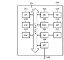
図4は、図1に示したクライアントPC101内のNETMAPの機能構成を示すブロック図である。本例は、PC101内のハードウエアであるCPUが実行するNETMAPの各機能に対応する。
FIG. 4 is a block diagram showing a functional configuration of NETMAP in the
本例は、ネットワークデバイスの状態に応じて機器制御コマンドの発行を制御する機能処理部の構成例である。 This example is a configuration example of a function processing unit that controls issuance of device control commands in accordance with the state of a network device.
図4において、NETMAP400には、ユーザが機器制御コマンドを作成するコマンド作成機能401と、作成した機器制御コマンドをメモリに保存するコマンド保持機能402とが設けられている。なお、コマンド保持機能402を実行のためのメモリは、RAM、HD等で構成される。
In FIG. 4, the
また、コマンド発行可否判別機能403は、機器制御コマンド発行の可否を後述するフローチャートの手順に基づいて判別する。
Further, the command issuance
具体的には、ルール記憶機能404で管理されるメモリに格納されているルールとネットワークデバイス状態記憶機能405に管理されるメモリに格納されているネットワークデバイスの状態とを用いて、機器制御コマンドの発行の可否を判別する。
Specifically, using the rules stored in the memory managed by the
ルール記憶機能404は、後述するUI画面を介して指示に基づいて、ユーザが作成したルールをメモリに記憶し、ネットワークデバイス状態記憶機能405は通信機能407経由でネットワークデバイスの状態を取得する。ここで、取得されるネットワークデバイスとは、図1に示すシステム例では、複合機102とするが、他のデバイスであってもよい。
The
コマンド発行可否判別機能403が機器制御コマンドの発行を可と判別した場合は、コマンド発行機能406、通信機能407を通して、機器制御コマンドがLAN100に送出される。
When the command
そして、LAN100に送出された機器制御コマンドを受信した複合機102は、受信したコマンド実行後、その処理結果をクライアントPC101に返信する。
Then, the multifunction peripheral 102 that has received the device control command sent to the
NETMAP400は、通信機能407にてコマンド実行結果を受け取ると、コマンド実行結果表示機能408が機器制御コマンドの実行結果をPC101が備える表示装置上に所定のUI画面を介して表示する。
When the
このようにPC101は、ネットワークに接続されたデバイスとNETMAP400を介して通信可能に構成され、以下の機能処理を実行する。複合機102等のデバイスの状態で異なる判別情報、例えばデバイスに対する操作の優先度と、デバイスの状態に応じて決定される情報に応じて、前記デバイスに対する操作する命令の発行を許可するかどうかを判別するための判別機能(コマンド発行可否判別機能403に対応する)を備える。
As described above, the
また、判別機能にて、前記デバイスに対する操作が許可された場合、前記デバイスに対して操作を実施するためのデバイス操作手段を有する。 In addition, when an operation for the device is permitted by the determination function, the device has a device operation means for performing the operation on the device.
さらに、NETMAP400は、判別情報に対して、前記デバイスに対して実施する操作の重要度を定めるための操作レベル値を定義する第1の定義機能と、判別情報に対して、前記操作を実施するユーザのユーザ権限レベル値を定義する第2の定義機能とを有し、第1、第2の定義機能により定義された各レベル値を含む前記判別情報に基づいて、前記デバイスに対する操作の可否を判別する。
Further, the
さらに、NETMAP400は、判別機能は、操作命令を発行する場合、前記操作を実行する旨を表示部に表示する(図5に示すステップS514で、機器制御コマンドの実行結果を一覧にしてユーザに表示する)。
Further, when the discriminating function issues an operation command, the
さて、NETMAP400が、複合機102の状態に応じて機器制御コマンドの発行を制御する場合、NETMAP400は、図5のフローチャートを実行する。
When the
図5は、本実施形態を示す情報処理装置における第1のデータ処理手順の一例を示すフローチャートである。本処理は、図1に示したPC101が図4に示した、NETMAP400を起動して行う機器制御コマンドの第1の発行処理例である。なお、S501〜S514は各ステップを示す。
FIG. 5 is a flowchart illustrating an example of a first data processing procedure in the information processing apparatus according to the present embodiment. This process is a first issuance process example of a device control command performed by the
まず、ステップS501では、NETMAP400のユーザが機器制御コマンドを作成する。次に、ステップS502で、ユーザは、ステップS501の機器制御コマンドを適用するネットワークデバイスを選定する。
First, in step S501, the user of
具体的には、ステップS501、ステップS502の動作を実現するために、コマンド作成機能401を利用する。この機能のGUI例を図6に示す。
Specifically, the
図6は、図1に示したクライアントPC101の表示装置に表示されるNETMAP400が提供するユーザインタフェースの一例を示す図である。
FIG. 6 is a diagram showing an example of a user interface provided by
図6において、600はメニュー一覧で、NETMAP400で作成可能な機器制御コマンドである。
In FIG. 6,
本実施形態において、メニュー一覧600から選択可能なメニュー項目は、デバイスへの設定610、デバイスのリセット620、デバイスへのリソースダウンロード630、デバイス状態監視640、デバイス探索650である。
In the present embodiment, menu items that can be selected from the
ここで、ユーザが、メニュー一覧600から機器制御コマンドとして、デバイスへの設定610を選択した場合、デバイスへの設定の作成ウィンドウ611が表示される。
When the user selects a device setting 610 from the
本作成ウィンドウ611内には、ネットワークデバイスのニックネームを入力するためのデバイス名入力テキストボックス(DNBOX)612、ネットワークデバイスの設置されている場所を入力するための設置場所入力テキストボックス613が設定されている。
In the
また、本作成ウィンドウ611内には、機器制御コマンドを実行する時刻を指定するためのコマンド実行時刻614、機器制御コマンドを実行する対象ネットワークデバイスを指定するための対象デバイス入力テキストボックス615が設定されている。対象デバイス入力テキストボックス615には、ユーザが複数のデバイスを任意に選択して設定可能に構成されている。
Also, in this
さらに、本作成ウィンドウ611内には、機器制御コマンドを実行する際に後述のルールを適用するかどうかを指定するルール適用ラジオボタン616、OKボタン617、および、キャンセルボタン618が存在する。
Further, in the
さて、図6に示すGUI例では、現在、NETMAP400のユーザは、デバイスへの設定の作成ウィンドウ611内のDNBOX612の値として「業務印刷用」、設置場所入力テキストボックス613の値として「居室A」を設定する。
In the GUI example shown in FIG. 6, the user of the
また、本GUI例では、コマンド実行時刻614の値として「指定時刻に実行する」、実行時刻として「01月01日 03時00分」を指定している状態に対応する。
Further, this GUI example corresponds to a state in which “execute at a specified time” is specified as the value of the
また、対象デバイス入力テキストボックス615は、「デバイスA」、「デバイスB」、「デバイスC」、「デバイスD」を指定している。
The target device
更に、ルール適用ラジオボタン616にて「コマンド実行時に、ルールを適用する」を選択することによって、機器制御コマンド実行時に後述のルールを適用することを宣言している。
Furthermore, by selecting “Apply rule when executing command” with the Apply
これらの値を入力または選択した後、ユーザがPC101が備える図示しないポインティングデバイス等を操作することで、OKボタン617を押下することによって、クライアントPC101のCPUが実行するNETMAP400により機器制御コマンドが作成される。
After inputting or selecting these values, a device control command is generated by the
なお、コマンド実行時刻614にて「今すぐ実行する」が選択されており、かつ、ルール適用ラジオボタン616にて「コマンド実行時に、ルールを適用する」が選択されている場合、OKボタン617押下時に、「本機器制御コマンドを本当に実行しますか?」というような確認ダイアログボックスを表示してもよい。以下、図5のフローチャートに戻って説明を続ける。
If “execute now” is selected at the
ステップS503では、ステップS501、ステップS502にて作成した機器制御コマンドをコマンド保持機能402によりユーザがPC101が備える図示しないメモリ上に保存する。
In step S503, the device control command created in steps S501 and S502 is saved by a
図7は、図4に示したコマンド保持機能402でメモリに保存される機器制御コマンドのコマンドフォーマットの一例を示す図である。
FIG. 7 is a diagram showing an example of a command format of a device control command stored in the memory by the
図7において、700は機器制御コマンドで、コマンドID710が「0001」の場合を示す。
In FIG. 7, 700 is a device control command, and shows a case where the
コマンドID710は機器制御コマンド毎に一意の値であれば、「0001」以外のどのような値であってもよい。
The
720はコマンド名であり、通常、メニュー一覧600に列挙されているメニュー項目の名称の内の1つが格納される。ここで、「デバイスへの設定」となる例である。
A
730はコマンド内容であり、機器制御コマンドの内容が格納される。本図においては、機器制御コマンド700の内容としてデバイス名731、設置場所732を例示しているが、この他にネットワーク設定などがあってもよい。
740は対象デバイスであり、本機器制御コマンドを送信するネットワークデバイスの情報が格納される。ここでは、デバイスAからDの4台が設定された例である。
750は対象デバイス台数であり、本機器制御コマンドを送信するネットワークデバイスの台数が格納される。本機器制御コマンドでは、ネットワークデバイスの台数をN台としている。ここでは、デバイスAからDの4台が設定された例であるので、N=4となる。
760はユーザ名であり、本機器制御コマンドを作成したユーザの名称「User1」が格納される。770は実行スケジュールであり、本機器制御コマンドが実行される日時「01月01日 03時00分」が格納される。
A
780はルール適用であり、本機器制御コマンドを実行する際に後述のルールを適用するかどうかの情報、現在「YES」を格納する。790はコマンドポイントであり、後述のルールに従って計算された本機器制御コマンドの持つポイント「8」を格納する。
さて、図5のフローチャートに戻って説明を続ける。 Returning to the flowchart of FIG.
ステップS504では、NETMAP400がPC101のワークメモリで管理される設定デバイス数を管理するための変数cntを「1」に初期化する。そして、ステップS505では、NETMAP400がステップS504にて初期化した変数cntが対象デバイス台数N(本実施形態では、「4」)以下かどうかを判別する。
In step S504, the
そして、NETMAP400がN以下であると判別された場合は、ステップS506に進み、NETMAP400がNより大きいと判別された場合は、ステップS514に進む。
If it is determined that
そして、ステップS506では、NETMAP400が、ステップS503で、メモリに保存した機器制御コマンドを実行する際に、後述のルールを適用するかどうかを判別する。
In step S506,
なお、本実施形態では、本ステップの判別には、図7に示したルール適用780が「YES」/「NO」を使用する。
In this embodiment, the
そして、ルール適用780において、ルールを適用する旨の記載がある(図7においては「YES」)場合は、ステップS507に進み、ルールを適用しない旨の記載がある(図7には不記載「NO」)場合は、ステップS512に進む。
Then, in the
そして、ステップS507では、NETMAP400が、ステップS503で保存した機器制御コマンドのポイントを計算する。
In step S507, the
ここで、図8を用いて、機器制御コマンドのポイントを計算するためのルールについて説明する。 Here, a rule for calculating the point of the device control command will be described with reference to FIG.
図8は、図4に示したルール記憶機能404が管理するコマンド種類別のポイント計算方法を説明する図である。
FIG. 8 is a diagram for explaining a point calculation method for each command type managed by the
図8において、800はルールそのものである。図8の(a)は、図6に示した各機器制御コマンドの種類とコマンドポイント(CP)の関係を表にしたものである。なお、本ルールは、ルール記憶機能404が管理するメモリに保存されている。
In FIG. 8, 800 is the rule itself. FIG. 8A is a table showing the relationship between the types of device control commands shown in FIG. 6 and command points (CP). This rule is stored in a memory managed by the
本例では、「デバイスへの設定」、「デバイスのリセット」、「リソースダウンロード」には5ポイント、「デバイス状態監視」には3ポイント、「デバイス探索」には1ポイントを割り当てている。 In this example, “point to device”, “reset device”, and “resource download” are assigned 5 points, “device status monitoring” is assigned 3 points, and “device search” is assigned 1 point.
図8の(b)は、ユーザ名とポイント(YP)の関係を表にしたものである。 FIG. 8B is a table showing the relationship between user names and points (YP).
本表では、User1、User2には5ポイント、User3、User4には3ポイントを割り当てている。
In this table, User1, the
図8の(c)は、機器制御コマンドのポイント計算式の例である。 (C) of FIG. 8 is an example of the point calculation formula of the device control command.
ここで、p、qは重み付けのための係数である。 Here, p and q are weighting coefficients.
本実施形態では、簡便化のため、p=1、q=1として考え、図8の(a)のポイント(CP)と、図8の(b)のポイント(YP)を加算したものを機器制御コマンドのポイントとするが、p、qは、任意の数値を指定することができる。 In this embodiment, for simplification, it is assumed that p = 1 and q = 1, and a device obtained by adding the point (CP) in FIG. 8A and the point (YP) in FIG. As a point of the control command, p and q can specify arbitrary numerical values.
図8の(d)は、ネットワークデバイスの状態毎に機器制御コマンドを発行することができるポイントの閾値を定めた対応表である。なお、ポイントの閾値は、図4に示したるルール記憶機能404が管理するメモリに記憶されて、後述するステップS510参照される。
FIG. 8D is a correspondence table that defines threshold values of points at which device control commands can be issued for each state of the network device. The point threshold value is stored in a memory managed by the
本対応表では、例えばネットワークデバイスの状態がスリープ中の場合、8ポイント以上を有する機器制御コマンドのみが実行できることを示している。さて、図5のフローチャートに戻って説明を続ける。 This correspondence table shows that, for example, when the state of the network device is sleeping, only the device control command having 8 points or more can be executed. Returning to the flowchart of FIG.
ステップS508では、NETMAP400がステップS507にて計算した機器制御コマンドのポイントの値がコマンドポイント790に格納されているかどうかを判別する。そして、NETMAP400がが格納されていると判別された場合は、ステップS510に進み、格納されていないと判別された場合は、ステップS509に進む。
In step S508, it is determined whether the point value of the device control command calculated by
そして、ステップS509では、NETMAP400がステップS507にて計算した機器制御コマンドのポイントを、図7に示したコマンドポイント790に格納する。
In step S509, the point of the device control command calculated by
次に、ステップS510では、対象デバイス740に格納されている、変数cntに設定された値の番目のネットワークデバイスの状態を取得して、ネットワークデバイス状態記憶機能405でメモリに記憶し、かつ、その状態に対応するポイントの閾値をルール記憶機能404によりメモリから取得する。
Next, in step S510, the state of the network device of the value of the value set in the variable cnt stored in the
なお、本実施形態において、ネットワークデバイスの状態を取得するには、第1の方法では、NETMAP400が、SNMPプロトコルなどを用いて、ネットワークデバイスに対して状態取得コマンドを送信する。第2の方法では、状態が変化した際に、ネットワークデバイスがNETMAP400に状態変化を通知する、などの方法が考えられる。
In this embodiment, in order to acquire the state of the network device, in the first method, the
そして、ステップS511では、NETMAP400がステップS507で計算したポイントとステップS510で取得したポイントの閾値を比較する。そして、NETMAP400がステップS507で計算したポイントがステップS510で取得したポイントの閾値以上であるかを判別する。 In step S511, it compares the threshold of points NETMAP400 acquired at points and step S510 calculated in step S50 7. Then, NETMAP400 point calculated in step S50 7, it is determined whether there are obtained points above the threshold value at step S510.
そして、取得したポイントの閾値以上であると判別した場合は、ステップS512に進む。 If it is determined that the acquired point is equal to or greater than the threshold value, the process proceeds to step S512.
一方、ステップS511で、NETMAP400がステップS507で計算したポイントがステップS510で取得したポイントの閾値より小さいと判別した場合は、ステップS513に進む。 On the other hand, in step S511, if NETMAP400 is determined to point calculated in step S50 7 is smaller than the threshold value of points earned in step S510, the program goes on to Step S513.
そして、ステップS512では、対象デバイス740に格納されている変数cntにセットされている値番目のネットワークデバイスに対して、コマンド発行機能406がコマンド保持機能402に保持されいている機器制御コマンドを発行する。なお、コマンド発行機能406が機器制御コマンドを発行する際には、通信機能407を経由する。
In step S512, the
そして、ステップS513では、変数cntを「1」だけ増加させ、ステップS505に戻る。 In step S513, the variable cnt is increased by “1”, and the process returns to step S505.
一方、ステップS505で、NETMAP400がステップS504にて初期化した変数cntが対象デバイス台数N以下でないと判断した場合は、最後に、ステップS514では、機器制御コマンドの実行結果を一覧にしてユーザに提示して、本処理を終了する。以上で本フローチャートは終了する。
On the other hand, if it is determined in step S505 that the variable cnt initialized by
図9は、図4に示したコマンド作成機能401で作成される機器制御コマンド実行結果一覧を示す図である。本例は、図5に示したステップS514にて作成される機器制御コマンド実行結果一覧の例である。
FIG. 9 is a diagram showing a list of device control command execution results created by the
図9において、900は機器制御コマンド実行結果一覧そのものである。910はデバイス名で、機器制御コマンドの実行対象となるネットワークデバイスが列挙される。920は実行結果で、デバイス名910に列挙されている各ネットワークデバイスに対して機器制御コマンドを実行した結果が列挙される
In FIG. 9, 900 is the device control command execution result list itself.
本例では、機器制御コマンドの実行が成功した場合に「成功」を表示し、失敗した場合に「失敗」を表示している。なお、本表示処理は、図4に示したコマンド実行結果表示機能408により実行される。また、デバイス名以外に、デバイスの設置場所を同時に表示してもよい。
In this example, “success” is displayed when the execution of the device control command is successful, and “failure” is displayed when it fails. This display process is executed by the command execution
さらに、ネットワークデバイスレイアウト等を表示して、その実行結果に応じて、デバイスの表示態様を変更することで、その実行結果を視覚的に表示してもよい。 Furthermore, the network device layout or the like may be displayed, and the execution result may be visually displayed by changing the display mode of the device according to the execution result.
また、図5のフローチャートを実行した結果、機器制御コマンドを実行しないと判別された場合には「実行せず」を表示している。 Further, when it is determined that the device control command is not executed as a result of executing the flowchart of FIG. 5, “not executed” is displayed.
次に、NETMAP400のユーザがルールを作成し、ルール記憶機能404に格納する際の動作を説明する。
Next, an operation when a user of the
図10は、本実施形態を示す情報処理装置における第2のデータ処理手順の一例を示すフローチャートである。本処理は、図1に示したPC101が図4に示した、NETMAP400を起動して行う機機器制御コマンド毎にポイントを割り当てるための処理例である。なお、S1001〜S1006は各ステップを示す。図8の(a)に示したポイントの例である。
FIG. 10 is a flowchart illustrating an example of a second data processing procedure in the information processing apparatus according to the present embodiment. This process is an example of a process for allocating points for each machine control command executed by activating the
まず、ステップS1001では、NETMAP400がメニュー一覧600に列挙されている機器制御コマンドの個数を計算する。ここでは、機器制御コマンドの個数がN(本実施形態では、図6の例に従うと、「5」となる)であると仮定する。
First, in step S1001, the
次に、NETMAP400がステップS1002では、コマンド個数をカウントするための変数cntを「1」に初期化する。ステップS1003で、NETMAP400がステップS1002にて初期化した変数cntが機器制御コマンドの個数N以下であり、かつ、ユーザが本フローチャートの処理を続行するかどうかを判別する。
Next, in step S1002, the
ここで、NETMAP400が初期化した変数cntが機器制御コマンドの個数N以下であり、かつ、ユーザが本フローチャートの処理を続行すると判別された場合は、ステップS1004に進む。
If the variable cnt initialized by the
一方、ステップS1003で、初期化した変数cntが機器制御コマンドの個数Nより大きい、または、ユーザが本フローチャートの処理を続行しないと判別された場合は、本フローチャートの処理を終了する。 On the other hand, if it is determined in step S1003 that the initialized variable cnt is greater than the number N of device control commands or the user does not continue the process of this flowchart, the process of this flowchart is terminated.
そして、ステップS1004では、NETMAP400がユーザが変数cntが示す値番目の機器制御コマンドのポイントを決定し、ステップS1005にてルール記憶機能404が管理するメモリに記憶する。
In step S1004, the
なお、機器制御コマンドのポイントは、デバイス状態の閾値との関係で相対的に決定されるものとする。つまり、デバイスがスリープ中で、できる限り各コマンドを発行しないにシステムデバイスを管理した場合と、それ以外では、設定すべきポイントが異なるからである。 Note that the point of the device control command is relatively determined in relation to the threshold value of the device state. In other words, the point to be set is different from the case where the device is in sleep and the system device is managed without issuing each command as much as possible.
そして、ステップS1006では、NETMAP400が変数cntを「1」だけ増加させ、ステップS1003に戻る。
In step S1006, the
以上で、図8の(a)に示した機器制御コマンドの種類とポイントの関係表が作成され、ステップS1005にてルール記憶機能404が管理するメモリに記憶した後、本フローチャートは終了する。
Thus, the device control command type and point relationship table shown in FIG. 8A is created and stored in the memory managed by the
図11は、図4に示したNETMAP400を起動して行う機器制御コマンド毎にポイントを割り当て指定画面の一例を示す図である Figure 11 is a diagram showing one example of an allocation specification screen points for each equipment control commands for Start NETMAP400 shown in FIG. 4
図において、1100はコマンドのポイント指定ウィンドウである。1101はコマンド名リストボックスであり、メニュー一覧600に列挙されている機器制御コマンドが表示される。なお、コマンド名リストボックス1101に機器制御コマンドを列挙する操作は図10のステップS1001で実現される。
In the figure,
1102はポイント入力テキストボックスであり、コマンド名リストボックス1101で現在表示している機器制御コマンドに対するポイントをユーザが入力するためのものである。
A point
なお、ポイント入力テキストボックス1102へのユーザによる入力操作は図10のステップS1004で実現される。
Note that an input operation by the user to the point
1103はOKボタンで、コマンドのポイント指定ウィンドウ1100に対する操作を確定するためのものである。
1104はキャンセルボタンであり、コマンドのポイント指定ウィンドウ1100に対する操作を破棄するためのものである。
なお、ポイント入力テキストボックス1102に設定する数値が、コマンド毎に、スリープ中のデバイスに対しての影響度合いを相対的に表示するガイドとともに、その数値の意味ユーザが理解し易いように表示してもよい。
The numerical value set in the point
図12は、本実施形態を示す情報処理装置における第3のデータ処理手順の一例を示すフローチャートである。本処理は、図1に示したPC101が図4に示した、NETMAP400を起動して行うユーザ毎にポイントを割り当てるための処理例である。なお、S1201〜S1206は各ステップを示す。
FIG. 12 is a flowchart illustrating an example of a third data processing procedure in the information processing apparatus according to the present embodiment. This processing is an example of processing for assigning points for each user performed by starting the
図13は、図4に示したNETMAP400を起動して行うユーザ毎にポイントを割り当て指定画面の一例を示す図である。
FIG. 13 is a diagram showing an example of a screen for assigning points for each user that is executed by starting the
本フローチャートは、以下の点を除いて、図10に示したフローチャートにおける「機器制御コマンド」を「ユーザ」に置き換えただけである。以下、その異なるステップS1201について説明する。 In this flowchart, except for the following points, the “device control command” in the flowchart shown in FIG. 10 is simply replaced with “user”. Hereinafter, the different step S1201 will be described.
ステップS1201では、NETMAP400のユーザ情報を参照して、ユーザ数を計算する。また、図13のGUI例と図11のGUI例の関係も同様である。よって、図12、図13の説明を省略する。
In step S1201, the number of users is calculated with reference to the user information of
以上で、図8の(b)に示したユーザ名とポイントの関係表が作成される。 Thus, the user name / point relationship table shown in FIG. 8B is created.
本実施形態では、ユーザポイントの値を高めにすると、設定すべきコマンドをルールを適用した場合でも実行される確率が高めとなり、管理者権限と同様に、その実行権限が相対的に設定可能に構成されている。 In this embodiment, if the value of the user point is increased, the probability that the command to be set will be executed even when a rule is applied is increased, and the execution authority can be set relatively, similar to the administrator authority. It is configured.
図14は、本実施形態を示す情報処理装置における第4のデータ処理手順の一例を示すフローチャートである。本処理は、図1に示したPC101が図4に示した、NETMAP400を起動して行うネットワークデバイスの状態毎に機器制御コマンドを実行できる閾値を割り当てるため処理例である。なお、S1401〜S1406は各ステップを示す。
FIG. 14 is a flowchart illustrating an example of a fourth data processing procedure in the information processing apparatus according to the present embodiment. This process is an example of processing for assigning a threshold value that can execute a device control command for each state of a network device performed by activating the
図15は、図4に示したNETMAP400を起動して行うネットワークデバイスの状態毎に機器制御コマンドを実行できる閾値の指定画面の一例を示す図である。
FIG. 15 is a diagram illustrating an example of a threshold designation screen that can execute a device control command for each state of a network device that is executed by starting up
なお、本フローチャートは、以下の点を除いて、図10のフローチャートにおける「機器制御コマンド」を「ネットワークデバイスの状態」に置き換えただけである。以下、その異なるステップS1401について説明する。 In this flowchart, except for the following points, “device control command” in the flowchart of FIG. 10 is simply replaced with “network device status”. Hereinafter, the different step S1401 will be described.
まず、ステップS1401では、NETMAP400の定義済みのネットワークデバイスの状態情報を参照して、定義済みのネットワークデバイスの状態数を計算する。また、図15のGUI例と図11のGUI例の関係も同様である。よって、図14、図15の説明を省略する。
First, in step S1401, the number of states of the defined network device is calculated with reference to the state information of the network device defined in
本実施形態では、実行できる閾値を高めにすると、デバイスとして、図8に示したコマンドポイントの値が超える確率が低くなり、例えばスリープ中状態で、PC側からのコマンド設定を制限できるよう機能する。 In the present embodiment, when the threshold value that can be executed is increased, the probability that the command point value shown in FIG. 8 is exceeded as a device is reduced, and for example, the function of limiting the command setting from the PC side in the sleep state. .
以上で、図8の(d)に示したネットワークデバイスの状態毎に機器制御コマンドを発行することができるポイントの閾値を定めた表が作成される。以上で、本第1実施形態の説明を終了する。 As described above, a table that defines threshold values of points at which device control commands can be issued for each state of the network device shown in FIG. 8D is created. This is the end of the description of the first embodiment.
このように本実施形態では、PC101は、ネットワーク(LAN100)に接続されたデバイスとNETMAP400を介して通信可能に構成されている。
As described above, in the present embodiment, the
そして、PC101で起動されるNETMAP400が、デバイスである複合機102の操作命令を発行するための機能として、属性の異なる機器制御コマンドを作成するための作成機能を備える。
The
また、PC101で起動されるNETMAP400が、デバイスに対する操作の優先度と、デバイスの状態とに応じた異なる各機器制御コマンド毎のコマンド発行ルールを設定する設定機能を備える。
Further, the
さらに、PC101で起動されるNETMAP400が、作成された前記機器制御コマンドに対する発行の可否を前記コマンド発行ルールに基づいて判別するコマンド発行可否判別機能403を備える。
Further, the
また、コマンド発行可否判別機能403により前記機器制御コマンドの発行が許可された場合、デバイスに対して作成された機器制御コマンドを発行するコマンド発行機能406を備える。
Further, a
また、コマンド発行ルールを適用の可否を指定する指定UI画面を図6に示すように表示する機能を備える。 In addition, a function of displaying a designation UI screen for designating whether to apply the command issuance rule as shown in FIG. 6 is provided.
そして、コマンド発行可否判別機能403は、コマンド発行ルールを適用するが指定されている場合、機器制御コマンドの発行の可否を判別する。
Then, the command
また、コマンド発行機能406は、デバイスに対する操作の優先度と、デバイスの状態に基づいてデバイスを操作する命令の発行を決定するための各機器制御コマンド毎のコマンド発行ルールを図8に示すように設定可能に構成されている。
Further, the
具体的には、コマンド発行可否判別機能403は、コマンド発行ルールに対して、各機器制御コマンドの属性毎、または機器制御コマンドを発行するユーザ毎に異なる発行レベルを設定可能に構成されている。
Specifically, the command
同様に、コマンド発行可否判別機能403、コマンド発行ルールに対して、各機器制御コマンドの発行の可否を決定する閾値を設定可能に構成されている。
Similarly, a threshold for determining whether or not each device control command can be issued can be set for the command
そして、コマンド発行可否判別機能403は、各機器制御コマンドの属性毎、または機器制御コマンドを発行するユーザ毎に異なるコマンド発行ルールで算定される要求値が閾値を超える場合(図5に示したステップS511でYES)に、各機器制御コマンドの発行を許可すると判別する。
Then, the command
さらに、機器制御コマンドの重要度を定めるためのユーザ権限の発行レベル、または機器制御コマンドの重要度を定めるための機器制御コマンド毎の発行レベルを設定可能に構成されている。 Further, the user authority issue level for determining the importance of the device control command or the issue level for each device control command for determining the importance of the device control command can be set.
また、コマンド発行機能406は、前記機器制御コマンドを発行する際に、前記機器制御コマンドを発行確認をユーザに通知する。
Further, when issuing the device control command, the
さらに、コマンド実行結果表示機能408は、コマンド発行機能406の発行結果を前記デバイスから取得して表示部に一覧表示する。
Further, the command execution
また、ルール記憶機能404は、設定された各機器制御コマンド毎のコマンド発行ルールをメモリに記憶させる。
Further, the
これにより、ネットワーク上のデバイスの状態とユーザ設定された発行ルールに基づいて、同一機器制御コマンドであっても、作成された機器制御コマンドを発行する場合と、発行しない場合とにコマンド発行態様を切り替え制御できる。 Thus, based on the state of the device on the network and the issuance rule set by the user, the command issuance mode can be changed depending on whether the created device control command is issued or not even if it is the same device control command. Switching control is possible.
したがって、デバイスの状態に適応したコマンド実行環境を自在に整備することができる。また、スリープモード中のデバイスを、強制的に動作可能状態にすることも、あるいは、スリープモード中に、属性の異なる各機器制御コマンド毎に、その実行態様を変更できる。 Therefore, it is possible to freely prepare a command execution environment adapted to the state of the device. In addition, the device in the sleep mode can be forcibly made operable, or the execution mode can be changed for each device control command having different attributes during the sleep mode.
〔第2実施形態〕
本実施形態は、NETMAP400が機器制御コマンドの発行を制御する際に、ネットワークデバイスの状態と機器制御コマンドの種類だけに依存する場合の例である。
[Second Embodiment]
This embodiment is an example of a case in which the
これを実現するために、図5のステップS507における機器制御コマンドのポイント計算において、図8の(a)に示した機器制御コマンドの種類とポイントの関係表と、図8の(d)に示したネットワークデバイスの状態毎に機器制御コマンドを発行することができるポイントの閾値を定めた表のみを使用する。 In order to realize this, in the point calculation of the device control command in step S507 in FIG. 5, the device control command type and point relationship table shown in FIG. 8A, and the device control command point shown in FIG. Only a table that defines a threshold of points at which device control commands can be issued for each state of the network device is used.
これは、第1実施形態で、図8の(c)の機器制御コマンドのポイント計算式において、p=1、q=1と指定した係数を、p=1、q=0と指定することと同等である。以上で、本実施形態の説明を終了する。 This is because, in the first embodiment, the coefficient specified as p = 1 and q = 1 in the point calculation formula of the device control command in FIG. 8C is specified as p = 1 and q = 0. It is equivalent. Above, description of this embodiment is complete | finished.
〔第3実施形態〕
本実施形態は、NETMAP400が機器制御コマンドの発行を制御する際に、ネットワークデバイスの状態とユーザ名だけに依存する場合の例である。
[Third Embodiment]
This embodiment is an example in which the
これを実現するために、図5のステップS507における機器制御コマンドのポイント計算において、図8の(b)に示したユーザ名とポイントの関係表と、図8(d)に示したネットワークデバイスの状態毎に機器制御コマンドを発行することができるポイントの閾値を定めた表のみを使用する。 In order to realize this, in the point calculation of the device control command in step S507 in FIG. 5, the user name / point relationship table shown in FIG. 8B and the network device shown in FIG. Only a table that defines a threshold of points at which device control commands can be issued for each state is used.
これは、第1実施形態で、図8の(c)の機器制御コマンドのポイント計算式において、p=1、q=1と指定した係数を、p=0、q=1と指定することと同等である。以上で、本実施形態の説明を終了する。 This is because, in the first embodiment, the coefficient specified as p = 1 and q = 1 in the point calculation formula of the device control command in FIG. 8C is specified as p = 0 and q = 1. It is equivalent. Above, description of this embodiment is complete | finished.
〔第4実施形態〕
本実施形態は、NETMAP400が機器制御コマンドの発行を制御する際に、図8の(c)の機器制御コマンドのポイント計算式を使わず、ネットワークデバイスの状態毎に作成されたマトリックスを基にする場合の例である。
[Fourth Embodiment]
In the present embodiment, when the
図16は、本実施形態を示す情報処理装置における第5のデータ処理手順の一例を示すフローチャートである。本処理は、図1に示したPC101が図4に示した、NETMAP400を起動して行う機器制御コマンドの第2の発行処理例である。なお、S1601〜S1610は各ステップを示す。
FIG. 16 is a flowchart illustrating an example of a fifth data processing procedure in the information processing apparatus according to the present embodiment. This process is a second issuance process example of a device control command performed by the
まず、ステップS1601からステップS1606までは、図5のステップS501からステップS506と同一であるため、説明を省略する。 First, steps S1601 to S1606 are the same as steps S501 to S506 in FIG.
そして、ステップS1607では、対象デバイス740に格納されている変数cntの値番目のネットワークデバイスの状態を取得してネットワークデバイス状態記憶機能405でメモリに記憶し、かつ、そのネットワークデバイスの状態に対応するルール適用マトリックス(詳細は後述する)をルール記憶機能404から取得する。
In step S1607, the state of the network device with the value of the variable cnt stored in the
そして、ステップS1608では、ステップS1607にて取得したルール適用マトリックスを用いて、機器制御コマンドが実行できるかどうかを判別する。 In step S1608, it is determined whether the device control command can be executed using the rule application matrix acquired in step S1607.
これ以降のステップS1609からステップS1611までは、図5のステップS512からステップS514と同一であるため、説明を省略する。以上で本フローチャートは終了する。 The subsequent steps S1609 to S1611 are the same as steps S512 to S514 in FIG. This flowchart is complete | finished above.
次に、図16のステップS1608で使用するルール適用マトリックスについて、図17を用いて説明する。 Next, the rule application matrix used in step S1608 in FIG. 16 will be described with reference to FIG.
図17は、図4に示したルール記憶機能404から取得するルール適用マトリックスの一例を示す図である。
FIG. 17 is a diagram illustrating an example of a rule application matrix acquired from the
図において、1700はルール適用マトリックスそのものである。1710はデバイス状態で、ネットワークデバイスが取り得る状態(待機中、印刷、スリープ中、ジャム解除待ち中等)を列挙する。1720はコマンド名で、メニュー一覧600に列挙されているメニュー項目の名称が列挙(本実施形態では、図6と同様に、5つの例)される。1730はユーザ名で、ネットワークデバイス管理アプリケーション400に登録されているユーザの名称(本実施形態では、図8と同様に、4名の例)が列挙される。なお、図中において、「○」が各状態毎に、それぞれのコマンドを許可されたユーザであることを示す。
In the figure, 1700 is the rule application matrix itself.
つまり、デバイス状態1710が、例えばスリープ中において、ユーザ1、2は、デバイスへの設定のコマンド、デバイスのリセットのコマンドを発行許可されているが、ユーザ3、4は、デバイスへの設定のコマンド、デバイスのリセットのコマンドを発行が禁止されている状態である。
That is, when the
本実施形態では、デバイスが省電力状態でなく、図17に示すように、待機中であれば、デバイスに対して情報を書き込む命令の発行を許可し、前記デバイスが印刷中であれば、前記デバイスに対して情報を書き込む命令の発行を許可しないとを判別機能で判別するため、判別ルールをユーザ名1730に示すユーザ1〜4に対して、異なる判別ルールを設定可能に構成されている。
In this embodiment, if the device is not in the power saving state and is in a standby state as shown in FIG. 17, it is allowed to issue a command to write information to the device, and if the device is printing, the device In order to discriminate by the discrimination function that issuing of an instruction to write information to the device is not permitted, different discrimination rules can be set for the
つまり、デバイスが省電力状態である場合にデバイスから情報取得要求を発行できるユーザ(図17に示す例では、ユーザ1、2に限定される)と、前記デバイスが省電力状態である場合に当該情報取得要求を発行できないユーザ(図17に示す例では、ユーザ3、4に限定される)とを定義した判別情報を用いて、判別機能が異なる判別ルールで判別処理を行えるように構成されている。
That is, when a device is in a power saving state, the user can issue an information acquisition request from the device (in the example shown in FIG. 17, limited to
ルール適用マトリックス1700では、これら3つの項目毎に、機器制御コマンド発行の可否が記載され、ルール記憶機能404が管理するメモリで記憶される。
In the
図16に示すステップS1608では、ルール適用マトリックス1700を用いて、機器制御コマンドが実行できるかどうかを判別する。以上で、本実施例の説明を終了する。
In step S1608 shown in FIG. 16, it is determined using the
〔第5実施形態〕
上記実施形態では、図4に示したルール記憶機能404により、PC内のメモリに設定された発行ルールを登録する場合について説明した。
[Fifth Embodiment]
In the above-described embodiment, a case has been described in which the issuance rule set in the memory in the PC is registered by the
しかしながら、発行ルールは、ネットワーク上で通信可能なサーバ装置等から取得してコマンド発行可否判別機能403が参照可能な構成であってもよい。
However, the issuance rule may be configured to be acquired from a server device or the like that can communicate on the network and to be referred to by the command
〔第6実施形態〕
以下、図18に示すメモリマップを参照して本発明に係る情報処理装置で読み取り可能なデータ処理プログラムの構成について説明する。
[Sixth Embodiment]
The configuration of a data processing program that can be read by the information processing apparatus according to the present invention will be described below with reference to the memory map shown in FIG.
図18は、本発明に係る情報処理装置で読み取り可能な各種データ処理プログラムを格納する記憶媒体のメモリマップを説明する図である。 FIG. 18 is a diagram for explaining a memory map of a storage medium for storing various data processing programs readable by the information processing apparatus according to the present invention.
なお、特に図示しないが、記憶媒体に記憶されるプログラム群を管理する情報、例えばバージョン情報,作成者等も記憶され、かつ、プログラム読み出し側のOS等に依存する情報、例えばプログラムを識別表示するアイコン等も記憶される場合もある。 Although not particularly illustrated, information for managing a program group stored in the storage medium, for example, version information, creator, etc. is also stored, and information depending on the OS on the program reading side, for example, a program is identified and displayed. Icons may also be stored.
さらに、各種プログラムに従属するデータも上記ディレクトリに管理されている。また、各種プログラムをコンピュータにインストールするためのプログラムや、インストールするプログラムが圧縮されている場合に、解凍するプログラム等も記憶される場合もある。 Further, data depending on various programs is also managed in the directory. In addition, a program for installing various programs in the computer, and a program for decompressing when the program to be installed is compressed may be stored.
本実施形態における図5、図10、図12、図14、図16に示す機能が外部からインストールされるプログラムによって、ホストコンピュータにより遂行されていてもよい。そして、その場合、CD−ROMやフラッシュメモリやFD等の記憶媒体により、あるいはネットワークを介して外部の記憶媒体から、プログラムを含む情報群を出力装置に供給される場合でも本発明は適用されるものである。 The functions shown in FIGS. 5, 10, 12, 14, and 16 in this embodiment may be performed by a host computer by a program installed from the outside. In this case, the present invention is applied even when an information group including a program is supplied to the output device from a storage medium such as a CD-ROM, a flash memory, or an FD, or from an external storage medium via a network. Is.
以上のように、前述した実施形態の機能を実現するソフトウエアのプログラムコードを記録した記憶媒体を、システムあるいは装置に供給する。そして、そのシステムあるいは装置のコンピュータ(またはCPUやMPU)が記憶媒体に格納されたプログラムコードを読出し実行することによっても、本発明の目的が達成されることは言うまでもない。 As described above, the storage medium storing the software program code for realizing the functions of the above-described embodiments is supplied to the system or apparatus. It goes without saying that the object of the present invention can also be achieved by the computer (or CPU or MPU) of the system or apparatus reading and executing the program code stored in the storage medium.
この場合、記憶媒体から読み出されたプログラムコード自体が本発明の新規な機能を実現することになり、そのプログラムコードを記憶した記憶媒体は本発明を構成することになる。 In this case, the program code itself read from the storage medium realizes the novel function of the present invention, and the storage medium storing the program code constitutes the present invention.
従って、プログラムの機能を有していれば、オブジェクトコード、インタプリタにより実行されるプログラム、OSに供給するスクリプトデータ等、プログラムの形態を問わない。 Therefore, as long as it has the function of the program, the form of the program such as an object code, a program executed by an interpreter, or script data supplied to the OS is not limited.
プログラムを供給するための記憶媒体としては、例えばフレキシブルディスク、ハードディスク、光ディスク、光磁気ディスク、MO、CD−ROM、CD−R、CD−RW、磁気テープ、不揮発性のメモリカード、ROM、DVDなどを用いることができる。 As a storage medium for supplying the program, for example, a flexible disk, hard disk, optical disk, magneto-optical disk, MO, CD-ROM, CD-R, CD-RW, magnetic tape, nonvolatile memory card, ROM, DVD, etc. Can be used.
この場合、記憶媒体から読出されたプログラムコード自体が前述した実施形態の機能を実現することになり、そのプログラムコードを記憶した記憶媒体は本発明を構成することになる。 In this case, the program code itself read from the storage medium realizes the functions of the above-described embodiments, and the storage medium storing the program code constitutes the present invention.
その他、プログラムの供給方法としては、クライアントコンピュータのブラウザを用いてインターネットのホームページに接続する。そして、該ホームページから本発明のコンピュータプログラムそのもの、もしくは、圧縮され自動インストール機能を含むファイルをハードディスク等の記録媒体にダウンロードすることによっても供給できる。また、本発明のプログラムを構成するプログラムコードを複数のファイルに分割し、それぞれのファイルを異なるホームページからダウンロードすることによっても実現可能である。つまり、本発明の機能処理をコンピュータで実現するためのプログラムファイルを複数のユーザに対してダウンロードさせるWWWサーバやftpサーバ等も本発明の請求項に含まれるものである。 As another program supply method, a browser on a client computer is used to connect to an Internet home page. Then, the computer program itself of the present invention or a compressed file including an automatic installation function can be downloaded from the homepage by downloading it to a recording medium such as a hard disk. It can also be realized by dividing the program code constituting the program of the present invention into a plurality of files and downloading each file from a different homepage. That is, a WWW server, an ftp server, and the like that allow a plurality of users to download a program file for realizing the functional processing of the present invention on a computer are also included in the claims of the present invention.
また、本発明のプログラムを暗号化してCD−ROM等の記憶媒体に格納してユーザに配布し、所定の条件をクリアしたユーザに対し、インターネットを介してホームページから暗号化を解く鍵情報をダウンロードさせる。そして、その鍵情報を使用することにより暗号化されたプログラムを実行してコンピュータにインストールさせて実現することも可能である。 In addition, the program of the present invention is encrypted, stored in a storage medium such as a CD-ROM, distributed to users, and key information for decryption is downloaded from a homepage via the Internet to users who have cleared predetermined conditions. Let It is also possible to execute the encrypted program by using the key information and install the program on a computer.
また、コンピュータが読み出したプログラムコードを実行することにより、前述した実施形態の機能が実現されるだけではない。例えばそのプログラムコードの指示に基づき、コンピュータ上で稼働しているOS(オペレーティングシステム)等が実際の処理の一部または全部を行う。そして、その処理によって前述した実施形態の機能が実現される場合も含まれることは言うまでもない。 In addition, the functions of the above-described embodiments are not only realized by executing the program code read by the computer. For example, based on an instruction of the program code, an OS (operating system) running on the computer performs part or all of the actual processing. Needless to say, the process includes the case where the functions of the above-described embodiments are realized.
さらに、記憶媒体から読み出されたプログラムコードが、コンピュータに挿入された機能拡張ボードやコンピュータに接続された機能拡張ユニットに備わるメモリに書き込ませる。その後、そのプログラムコードの指示に基づき、その機能拡張ボードや機能拡張ユニットに備わるCPU等が実際の処理の一部または全部を行い、その処理によって前述した実施形態の機能が実現される場合も含まれることは言うまでもない。 Further, the program code read from the storage medium is written in a memory provided in a function expansion board inserted into the computer or a function expansion unit connected to the computer. After that, based on the instruction of the program code, the CPU of the function expansion board or function expansion unit performs part or all of the actual processing, and the processing of the above-described embodiment is realized by the processing. Needless to say.
本発明は上記実施形態に限定されるものではなく、本発明の趣旨に基づき種々の変形(各実施形態の有機的な組合せを含む)が可能であり、それらを本発明の範囲から排除するものではない。 The present invention is not limited to the above embodiments, and various modifications (including organic combinations of the embodiments) are possible based on the spirit of the present invention, and these are excluded from the scope of the present invention. is not.
本発明の様々な例と実施形態を示して説明したが、当業者であれば、本発明の趣旨と範囲は、本明細書内の特定の説明に限定されるのではない。 Although various examples and embodiments of the present invention have been shown and described, those skilled in the art will not limit the spirit and scope of the present invention to the specific description in the present specification.
400 NETMAP
401 コマンド作成機能
402 コマンド保持機能
403 コマンド発行可否判別機能
404 ルール記憶機能
405 ネットワークデバイス状態記憶機能
406 コマンド発行機能
407 通信機能
400 NETMAP
401
Claims (7)
機器制御コマンド毎に割り当てられたポイントと、ユーザ毎に割り当てられたポイントと、前記デバイスを含むネットワークデバイスの状態毎に割り当てられた前記機器制御コマンドを発行することが可能となる複数の閾値とを記憶する記憶手段と、
前記デバイスの状態を取得する取得手段と、
前記デバイスに対して操作を実施する場合、前記操作に対応する所定の機器制御コマンドに割り当てられたポイントと、前記操作を実施するユーザに割り当てられたポイントと、前記取得手段により取得されたデバイスの状態に割り当てられている閾値とを前記記憶手段から取得し、
取得した前記所定の機器制御コマンドに割り当てられたポイントと、前記操作を実施するユーザに割り当てられたポイントとを計算した値が、前記取得されたデバイスの状態に割り当てられている閾値以上となるか否かに基づき、前記デバイスを操作するための前記機器制御コマンドの発行を許可するかどうかを判別するための判別手段と、
前記判別手段にて、前記計算した値が前記閾値未満となり前記デバイスに対する操作が許可されなかった場合、前記デバイスに対して前記操作に対応する機器制御コマンドを発行せず、前記計算した値が前記閾値以上となり前記デバイスに対する操作が許可された場合、前記デバイスに対して前記操作に対応する機器制御コマンドを発行するためのデバイス操作手段と、
を有することを特徴とする情報処理装置。 An information processing apparatus capable of communicating with a device connected to a network via a network management application,
A point assigned for each device control command, a point assigned for each user, and a plurality of threshold values that can issue the device control command assigned for each state of a network device including the device. Storage means for storing;
Obtaining means for obtaining the state of the device;
When performing an operation on the device, a point assigned to a predetermined device control command corresponding to the operation, a point assigned to a user who performs the operation, and a device acquired by the acquisition unit Obtaining the threshold value assigned to the state from the storage means;
Whether the calculated value of the points assigned to the acquired predetermined device control command and the points assigned to the user performing the operation is equal to or greater than the threshold value assigned to the acquired device status Determining means for determining whether or not to permit the issuance of the device control command for operating the device based on whether or not ,
In the determination unit, when the calculated value is less than the threshold value and the operation on the device is not permitted, the device control command corresponding to the operation is not issued to the device, and the calculated value is A device operation means for issuing a device control command corresponding to the operation to the device when an operation on the device is permitted above the threshold ;
An information processing apparatus comprising:
前記判別手段は、前記指定された対象デバイス毎に前記計算した値が、前記取得手段により取得された状態に割り当てられた閾値以上となるか否かに基づき判別を行うことで、前記対象デバイス毎に前記制御コマンドの発行を許可するかどうかを切り替えることが可能になることを特徴とする請求項1に記載の情報処理装置。The determination unit performs determination based on whether or not the calculated value for each of the designated target devices is equal to or greater than a threshold value assigned to the state acquired by the acquisition unit. The information processing apparatus according to claim 1, wherein whether or not to permit the issue of the control command can be switched.
機器制御コマンド毎に割り当てられたポイントと、ユーザ毎に割り当てられたポイントと、前記デバイスを含むネットワークデバイスの状態毎に割り当てられた前記機器制御コマンドを発行することが可能となる複数の閾値とを記憶手段に記憶する記憶ステップと、
前記デバイスの状態を取得する取得ステップと、
前記デバイスに対して操作を実施する場合、前記操作に対応する所定の機器制御コマンドに割り当てられたポイントと、前記操作を実施するユーザに割り当てられたポイントと、前記取得ステップにより取得されたデバイスの状態に割り当てられている閾値とを前記記憶手段から取得し、
取得した前記所定の機器制御コマンドに割り当てられたポイントと、前記操作を実施するユーザに割り当てられたポイントとを計算した値が、前記取得されたデバイスの状態に割り当てられている閾値以上となるか否かに基づき、前記デバイスを操作するための前記機器制御コマンドの発行を許可するかどうかを判別するための判別ステップと、
前記判別ステップにて、前記計算した値が前記閾値未満となり前記デバイスに対する操作が許可されなかった場合、前記デバイスに対して前記操作に対応する機器制御コマンドを発行せず、前記計算した値が前記閾値以上となり前記デバイスに対する操作が許可された場合、前記デバイスに対して前記操作に対応する機器制御コマンドを発行するためのデバイス操作ステップと、
を有することを特徴とするデバイス管理方法。 A device management method in an information processing apparatus capable of communicating with a device connected to a network via a network management application,
A point assigned for each device control command, a point assigned for each user, and a plurality of threshold values that can issue the device control command assigned for each state of a network device including the device. A storage step of storing in the storage means;
An acquisition step of acquiring the state of the device;
When performing an operation on the device, a point assigned to a predetermined device control command corresponding to the operation, a point assigned to a user who performs the operation, and the device acquired by the acquisition step Obtaining the threshold value assigned to the state from the storage means;
Whether the calculated value of the points assigned to the acquired predetermined device control command and the points assigned to the user performing the operation is equal to or greater than the threshold value assigned to the acquired device status A determination step for determining whether to permit issuing the device control command for operating the device based on whether or not ,
In the determination step, when the calculated value is less than the threshold value and the operation on the device is not permitted, the device control command corresponding to the operation is not issued to the device, and the calculated value is A device operation step for issuing a device control command corresponding to the operation to the device, when an operation on the device is permitted above the threshold ;
A device management method comprising:
Priority Applications (2)
| Application Number | Priority Date | Filing Date | Title |
|---|---|---|---|
| JP2006053344A JP4789653B2 (en) | 2006-02-28 | 2006-02-28 | Information processing apparatus, device management method, and program |
| US11/675,000 US8326957B2 (en) | 2006-02-28 | 2007-02-14 | Information processing apparatus and device management method |
Applications Claiming Priority (1)
| Application Number | Priority Date | Filing Date | Title |
|---|---|---|---|
| JP2006053344A JP4789653B2 (en) | 2006-02-28 | 2006-02-28 | Information processing apparatus, device management method, and program |
Publications (3)
| Publication Number | Publication Date |
|---|---|
| JP2007233611A JP2007233611A (en) | 2007-09-13 |
| JP2007233611A5 JP2007233611A5 (en) | 2009-04-09 |
| JP4789653B2 true JP4789653B2 (en) | 2011-10-12 |
Family
ID=38443679
Family Applications (1)
| Application Number | Title | Priority Date | Filing Date |
|---|---|---|---|
| JP2006053344A Expired - Fee Related JP4789653B2 (en) | 2006-02-28 | 2006-02-28 | Information processing apparatus, device management method, and program |
Country Status (2)
| Country | Link |
|---|---|
| US (1) | US8326957B2 (en) |
| JP (1) | JP4789653B2 (en) |
Families Citing this family (8)
| Publication number | Priority date | Publication date | Assignee | Title |
|---|---|---|---|---|
| US8108914B2 (en) | 2006-04-25 | 2012-01-31 | Vetrix, Llc | Converged logical and physical security |
| US8413138B2 (en) * | 2008-02-06 | 2013-04-02 | Mformation Software Technologies, Inc. | System and method to securely load a management client from a stub client to facilitate remote device management |
| JP5037376B2 (en) * | 2008-02-06 | 2012-09-26 | 株式会社リコー | Information processing apparatus, power mode control method, power mode control program, and recording medium |
| WO2010080821A1 (en) * | 2009-01-06 | 2010-07-15 | Vetrix, Llc | Integrated physical and logical security management via a portable device |
| WO2010102176A1 (en) | 2009-03-06 | 2010-09-10 | Vetrix, Llc | Systems and methods for mobile tracking, communications and alerting |
| CN101577845B (en) * | 2009-06-01 | 2012-11-14 | 中兴通讯股份有限公司 | Method and device for processing switching control command |
| JP5645647B2 (en) | 2010-03-01 | 2014-12-24 | キヤノン株式会社 | Power control system and control method thereof |
| JP2012003491A (en) * | 2010-06-16 | 2012-01-05 | Mitsubishi Electric Corp | Data processing device and data processing method |
Family Cites Families (14)
| Publication number | Priority date | Publication date | Assignee | Title |
|---|---|---|---|---|
| JP2001187480A (en) * | 2000-01-04 | 2001-07-10 | Minolta Co Ltd | Apparatus control equipment |
| JP2001358877A (en) * | 2000-06-09 | 2001-12-26 | Canon Inc | Image processor, information processor, image processing system, message display control method and storage medium |
| JP3559757B2 (en) * | 2000-08-22 | 2004-09-02 | キヤノン株式会社 | Communication method and communication device |
| US20020044295A1 (en) * | 2000-10-16 | 2002-04-18 | Olympus Optical Co., Ltd. | Printer device |
| JP2003316557A (en) * | 2002-04-24 | 2003-11-07 | Canon Inc | Image formation system, image formation management method and its server |
| JP4134916B2 (en) * | 2003-02-14 | 2008-08-20 | 松下電器産業株式会社 | Network connection device and network connection switching method |
| JP2004326544A (en) * | 2003-04-25 | 2004-11-18 | Canon Inc | Printing system |
| JP4057986B2 (en) * | 2003-09-19 | 2008-03-05 | 株式会社リコー | Network device, energy saving control method and energy saving control program |
| US7752470B2 (en) * | 2003-12-03 | 2010-07-06 | International Business Machines Corporation | Method and system for power management including device controller-based device use evaluation and power-state control |
| JP4725038B2 (en) * | 2004-06-03 | 2011-07-13 | ソニー株式会社 | Content sharing system and content importance determination method |
| WO2006082732A1 (en) * | 2005-02-04 | 2006-08-10 | Nec Corporation | Access control unit |
| US7373471B2 (en) * | 2005-02-09 | 2008-05-13 | International Business Machines Corporation | Executing background writes to idle DIMMs |
| JP2006277714A (en) * | 2005-03-01 | 2006-10-12 | Seiko Epson Corp | Output system, device management apparatus and program, and output method |
| US20060279256A1 (en) * | 2005-06-10 | 2006-12-14 | Media Lab | Power management system for multi-function battery-operated device |
-
2006
- 2006-02-28 JP JP2006053344A patent/JP4789653B2/en not_active Expired - Fee Related
-
2007
- 2007-02-14 US US11/675,000 patent/US8326957B2/en not_active Expired - Fee Related
Also Published As
| Publication number | Publication date |
|---|---|
| JP2007233611A (en) | 2007-09-13 |
| US20070201080A1 (en) | 2007-08-30 |
| US8326957B2 (en) | 2012-12-04 |
Similar Documents
| Publication | Publication Date | Title |
|---|---|---|
| JP4789653B2 (en) | Information processing apparatus, device management method, and program | |
| JP4636933B2 (en) | Print control apparatus and print control method | |
| JP3720740B2 (en) | Distributed printing system, distributed printing control method, storage medium, and program | |
| JP5975666B2 (en) | Information processing apparatus, information processing method, and program | |
| JP5321929B2 (en) | Universal device driver, device control program, information processing apparatus, server apparatus, and method | |
| JP2009075772A (en) | Print instruction apparatus, printing apparatus, printing system, and program | |
| JP5696470B2 (en) | DEVICE MANAGEMENT DEVICE, DEVICE MANAGEMENT METHOD, DEVICE MANAGEMENT PROGRAM, AND RECORDING MEDIUM CONTAINING THE PROGRAM | |
| JP5786439B2 (en) | PRINT CONTROL DEVICE, PRINT CONTROL SYSTEM, PRINT CONTROL PROGRAM, AND RECORDING MEDIUM CONTAINING THE PROGRAM | |
| JP2015056169A (en) | Output system, terminal device, program, and output method | |
| JP5288981B2 (en) | Information processing apparatus, control method therefor, and program | |
| JP2006195531A (en) | Image recording system | |
| JP6481508B2 (en) | Terminal device, program, and output system | |
| JP4886501B2 (en) | Printing apparatus, printing control method, and program | |
| JP2009181337A (en) | Image forming system, management device, and image forming apparatus, method and program | |
| JP2008276471A (en) | Information processor, print setting method, storage medium and program | |
| CN110764720B (en) | Printing apparatus, control method of printing apparatus, and storage medium | |
| JP2007087130A (en) | Server device, print processing method of server device, storage medium and program | |
| US9270853B2 (en) | Exporting and importing for display on an image forming apparatus environment setting information of an application | |
| JP5625497B2 (en) | Information processing apparatus, information processing system, information processing method, program, and recording medium storing the program | |
| JP2010214725A (en) | Printer and printing system and method of controlling printer | |
| JP2008176674A (en) | Electronic apparatus, service provision method and program | |
| JP2009122745A (en) | Printing instruction device, printing system, and program | |
| JP7247780B2 (en) | Image forming device, information processing device and program | |
| JP2008102848A (en) | Information processor, its control method, and program | |
| JP2012059280A (en) | Printer, data processing apparatus, printing control method, and program |
Legal Events
| Date | Code | Title | Description |
|---|---|---|---|
| RD03 | Notification of appointment of power of attorney |
Free format text: JAPANESE INTERMEDIATE CODE: A7423 Effective date: 20080108 |
|
| RD04 | Notification of resignation of power of attorney |
Free format text: JAPANESE INTERMEDIATE CODE: A7424 Effective date: 20080220 |
|
| A521 | Request for written amendment filed |
Free format text: JAPANESE INTERMEDIATE CODE: A523 Effective date: 20090223 |
|
| A621 | Written request for application examination |
Free format text: JAPANESE INTERMEDIATE CODE: A621 Effective date: 20090223 |
|
| A977 | Report on retrieval |
Free format text: JAPANESE INTERMEDIATE CODE: A971007 Effective date: 20110127 |
|
| A131 | Notification of reasons for refusal |
Free format text: JAPANESE INTERMEDIATE CODE: A131 Effective date: 20110215 |
|
| A521 | Request for written amendment filed |
Free format text: JAPANESE INTERMEDIATE CODE: A523 Effective date: 20110407 |
|
| TRDD | Decision of grant or rejection written | ||
| A01 | Written decision to grant a patent or to grant a registration (utility model) |
Free format text: JAPANESE INTERMEDIATE CODE: A01 Effective date: 20110712 |
|
| A01 | Written decision to grant a patent or to grant a registration (utility model) |
Free format text: JAPANESE INTERMEDIATE CODE: A01 |
|
| A61 | First payment of annual fees (during grant procedure) |
Free format text: JAPANESE INTERMEDIATE CODE: A61 Effective date: 20110719 |
|
| FPAY | Renewal fee payment (event date is renewal date of database) |
Free format text: PAYMENT UNTIL: 20140729 Year of fee payment: 3 |
|
| LAPS | Cancellation because of no payment of annual fees |