JP4786902B2 - Mechanical method and instrument for bilateral tissue fixation - Google Patents
Mechanical method and instrument for bilateral tissue fixation Download PDFInfo
- Publication number
- JP4786902B2 JP4786902B2 JP2004516211A JP2004516211A JP4786902B2 JP 4786902 B2 JP4786902 B2 JP 4786902B2 JP 2004516211 A JP2004516211 A JP 2004516211A JP 2004516211 A JP2004516211 A JP 2004516211A JP 4786902 B2 JP4786902 B2 JP 4786902B2
- Authority
- JP
- Japan
- Prior art keywords
- tissue
- fastener
- skin
- pair
- opening
- Prior art date
- Legal status (The legal status is an assumption and is not a legal conclusion. Google has not performed a legal analysis and makes no representation as to the accuracy of the status listed.)
- Expired - Lifetime
Links
Images


Classifications
-
- A—HUMAN NECESSITIES
- A61—MEDICAL OR VETERINARY SCIENCE; HYGIENE
- A61B—DIAGNOSIS; SURGERY; IDENTIFICATION
- A61B17/00—Surgical instruments, devices or methods, e.g. tourniquets
- A61B17/064—Surgical staples, i.e. penetrating the tissue
- A61B17/0644—Surgical staples, i.e. penetrating the tissue penetrating the tissue, deformable to closed position
-
- A—HUMAN NECESSITIES
- A61—MEDICAL OR VETERINARY SCIENCE; HYGIENE
- A61B—DIAGNOSIS; SURGERY; IDENTIFICATION
- A61B17/00—Surgical instruments, devices or methods, e.g. tourniquets
- A61B17/064—Surgical staples, i.e. penetrating the tissue
-
- A—HUMAN NECESSITIES
- A61—MEDICAL OR VETERINARY SCIENCE; HYGIENE
- A61B—DIAGNOSIS; SURGERY; IDENTIFICATION
- A61B17/00—Surgical instruments, devices or methods, e.g. tourniquets
- A61B17/068—Surgical staplers, e.g. containing multiple staples or clamps
-
- A—HUMAN NECESSITIES
- A61—MEDICAL OR VETERINARY SCIENCE; HYGIENE
- A61B—DIAGNOSIS; SURGERY; IDENTIFICATION
- A61B17/00—Surgical instruments, devices or methods, e.g. tourniquets
- A61B17/068—Surgical staplers, e.g. containing multiple staples or clamps
- A61B17/0682—Surgical staplers, e.g. containing multiple staples or clamps for applying U-shaped staples or clamps, e.g. without a forming anvil
-
- A—HUMAN NECESSITIES
- A61—MEDICAL OR VETERINARY SCIENCE; HYGIENE
- A61B—DIAGNOSIS; SURGERY; IDENTIFICATION
- A61B17/00—Surgical instruments, devices or methods, e.g. tourniquets
- A61B17/28—Surgical forceps
- A61B17/2812—Surgical forceps with a single pivotal connection
- A61B17/282—Jaws
-
- A—HUMAN NECESSITIES
- A61—MEDICAL OR VETERINARY SCIENCE; HYGIENE
- A61B—DIAGNOSIS; SURGERY; IDENTIFICATION
- A61B17/00—Surgical instruments, devices or methods, e.g. tourniquets
- A61B17/30—Surgical pincettes without pivotal connections
-
- A—HUMAN NECESSITIES
- A61—MEDICAL OR VETERINARY SCIENCE; HYGIENE
- A61B—DIAGNOSIS; SURGERY; IDENTIFICATION
- A61B17/00—Surgical instruments, devices or methods, e.g. tourniquets
- A61B2017/00004—(bio)absorbable, (bio)resorbable, resorptive
-
- A—HUMAN NECESSITIES
- A61—MEDICAL OR VETERINARY SCIENCE; HYGIENE
- A61B—DIAGNOSIS; SURGERY; IDENTIFICATION
- A61B17/00—Surgical instruments, devices or methods, e.g. tourniquets
- A61B17/08—Wound clamps or clips, i.e. not or only partly penetrating the tissue ; Devices for bringing together the edges of a wound
- A61B2017/081—Tissue approximator
Landscapes
- Health & Medical Sciences (AREA)
- Life Sciences & Earth Sciences (AREA)
- Surgery (AREA)
- Heart & Thoracic Surgery (AREA)
- Engineering & Computer Science (AREA)
- Biomedical Technology (AREA)
- Nuclear Medicine, Radiotherapy & Molecular Imaging (AREA)
- Medical Informatics (AREA)
- Molecular Biology (AREA)
- Animal Behavior & Ethology (AREA)
- General Health & Medical Sciences (AREA)
- Public Health (AREA)
- Veterinary Medicine (AREA)
- Surgical Instruments (AREA)
- Prostheses (AREA)
Description
本発明は、外科用ステープラ、クリップアプリケータ、無縫合閉鎖器具等の外科用器具の分野全般に関する。特に、本発明は、皮膚組織等の組織を、組織面下に位置決めされている留め具であって組織の対向する片を両側に固定する留め具によって固定するための機械的方法及び機器に関する。 The present invention relates generally to the field of surgical instruments such as surgical staplers, clip applicators, and sutureless closure instruments. In particular, the present invention relates to a mechanical method and apparatus for fixing tissue, such as skin tissue, with fasteners that are positioned below the tissue plane and that fix opposing pieces of tissue to both sides.
意図的な切開、又は不慮の創傷や裂傷によって組織に開口部が形成された場合、対向する生存組織面の近傍において、開口部の生物学的治癒が開始する。開口部が非常に大きい場合、又はその位置のために創傷が絶えず動く場合、医師は治癒の進行を促進するために、近接する開口部の側部を強制的に保持しようとするであろう。 When an opening is formed in tissue by intentional incision or accidental wound or laceration, biological healing of the opening begins in the vicinity of the opposing living tissue surface. If the opening is very large, or if the wound constantly moves because of its location, the physician will try to force the sides of the adjacent opening to be forced to promote healing progress.
皮膚組織の場合、例えば、皮膚組織の対向する真皮層を互いに近接させて保持すると、最良の治癒が得られる。ヒト皮膚組織は、3つの明確な組織層を備えている。表皮としても知られる表皮層は、最外層であって、非生存組織細胞を含んでいる。真皮すなわち真皮層は、表皮層の直下にある中間層であって、3つの層の中で最も強い皮膚の生存組織を備えている。皮下層すなわち皮下組織層は、皮膚組織の最下層であって、結合組織の含有量が少ないため皮膚組織の中で最も弱い層である。 In the case of skin tissue, for example, best healing is obtained if the opposing dermal layers of the skin tissue are held close together. Human skin tissue has three distinct tissue layers. The epidermal layer, also known as the epidermis, is the outermost layer and contains non-viable tissue cells. The dermis or dermis layer is an intermediate layer directly below the epidermis layer, with the strongest skin surviving tissue of the three layers. The subcutaneous layer, i.e., the subcutaneous tissue layer, is the lowest layer of the skin tissue and is the weakest layer in the skin tissue because of the low content of connective tissue.
組織の開口部を強制的に閉合するための最も一般的な方法は、縫合糸すなわち「縫糸」を使用する方法である。早くも2世紀に、ギリシャ人は皮膚開口部を物理的に閉合するために縫合糸を使用していた。最も簡単な形態において、縫合糸は単に1本の材料であって、針等の組織貫通器具に取り付けられて、開口部の対向する側部にループ状にくくりつけられる。このとき、縫合糸が強く引っ張られてループが閉じられるので、組織の対向する側部は物理的に近接した状態になる。縫合糸のループは、結び目を作ることによって、又はその他の固定機器によってしっかりと保持される。当初の縫合糸は、動物の腸で作られた。次第に、皮、馬毛、亜麻、綿、絹を含むその他の天然縫合糸材料が使用されるようになった。 The most common method for forcibly closing a tissue opening is to use a suture or “sewing”. As early as the second century, the Greeks used sutures to physically close the skin openings. In the simplest form, the suture is simply a single material that is attached to a tissue penetrating instrument such as a needle and is looped to the opposite side of the opening. At this time, the suture is pulled strongly and the loop is closed, so that the opposing side portions of the tissue are in physical proximity. The suture loop is held securely by tying a knot or other fastening device. The original suture was made in the animal's intestine. Increasingly, other natural suture materials were used, including skin, horse hair, flax, cotton and silk.
前世紀に渡る医学と材料技術の進歩に伴い、新しい生体再吸収性材料が開発され、基本的な縫合概念は更に改良されている。縫合処置に関する近代の改良例としては、例えば米国特許第2,439,383号、第2,959,172号、第3,344,790号に記載の縫合機器に関する機能強化、並びに例えば米国特許第3,123,077号、第3,297,033号、第3,636,956号、第3,792,010号、第4,027,676号、第4,047,533号に記載の縫合糸と縫合材料に関する改良が挙げられる。 With the advance of medicine and material technology over the last century, new bioresorbable materials have been developed and the basic suturing concept has been further improved. Modern improvements relating to suturing procedures include, for example, enhancements to the suturing device described in US Pat. Nos. 2,439,383, 2,959,172, 3,344,790, and, for example, US Pat. Sutures described in 3,123,077, 3,297,033, 3,636,956, 3,792,010, 4,027,676, 4,047,533 Improvements related to thread and suture materials.
従来の縫合が皮膚の開口部を閉合する一般的な方法であり続けている一方で、皮膚閉合技術としてステープルやステープラを使用することが、特に開口部が意図的な切開によって形成される外科環境において、ますます一般的になっている。これらの環境では、切開によって、きれいな一直線の切り口であって、一貫したギザギザ状でない表面を有する切開部の対向する側部を有する切り口が形成されることが多い。通常、皮膚開口部のステープリングは、例えば、皮膚開口部の対向する側部を用手で近接させてから、ステープルが開口部に架け渡されるようにステープラの位置決めを行うことによって実施される。このときステープラは、ステープルの1つの脚が皮膚の各側部に挿入され、かつステープルの横材が皮膚面の開口部外面に架け渡される状態でステープルが皮膚に挿入されるように操作される。一般にステープルの脚は、アンビルに挿入される。したがってステープルは、皮膚組織をステープル内で圧縮して保持するように変形する。この処置は、治癒の進行中に切開部全体が閉合状態に保たれるよう、開口部の長さに沿って繰り返される。 While conventional suturing continues to be a common method of closing skin openings, the use of staples and staplers as skin closure techniques, especially in surgical environments where the openings are formed by intentional incisions Is becoming more and more common. In these environments, the incision often forms a clean, straight cut that has opposite sides of the cut with a consistent non-gray surface. Usually, stapling of the skin opening is performed, for example, by positioning the stapler so that the opposing side portions of the skin opening are brought close to each other by a hand and then the staple is spanned over the opening. At this time, the stapler is operated so that the staple is inserted into the skin in a state where one leg of the staple is inserted into each side of the skin and the cross member of the staple is stretched over the outer surface of the opening of the skin surface. . Generally, the staple legs are inserted into the anvil. Thus, the staple is deformed to compress and hold the skin tissue within the staple. This procedure is repeated along the length of the opening so that the entire incision is kept closed as healing progresses.
基本的なステープリング処置を改良するために、多くの研究が行われてきた。研究は多様な方面に及び、例えば米国特許第3,082,426号、第3,643,851号、第4,410,125号、第4,493,322号、第4,592,498号、第4,618,086号、第4,776,506号、第4,915,100号、第5,044,540号、第5,129,570号、第5,285,944号、第5,392,979号、第5,489,058号、第5,551,622号、第5,662,258号、第5,794,834号、第5,816,471号、第6,131,789号、第6,250,532号に記載のステープリング機器に関する研究が挙げられる。ステープリング機器の他にも、研究は、例えば米国特許第2,351,608号、第2,526,902号、第2,881,762号、第3,757,629号、第4,014,492号、第4,261,244号、第4,317,451号、第4,407,286号、第4,428,376号、第4,485,816号、第4,505,273号、第4,526,174号、第4,570,623号、第4,719,917号、第4,741,337号、第5,007,921号、第5,158,567号、第5,258,009号、第5,297,714号、第5,324,307号、第5,413,584号、第5,505,363号、第5,571,285号に記載のステープル設計に関しても行われている。 Much work has been done to improve the basic stapling procedure. The research covers various aspects, for example, U.S. Pat. Nos. 3,082,426, 3,643,851, 4,410,125, 4,493,322, 4,592,498. 4,618,086, 4,776,506, 4,915,100, 5,044,540, 5,129,570, 5,285,944, 5,392,979, 5,489,058, 5,551,622, 5,662,258, 5,794,834, 5,816,471, Studies on stapling devices described in 131,789 and 6,250,532 can be cited. In addition to stapling equipment, research has been conducted, for example, in U.S. Pat. Nos. 2,351,608, 2,526,902, 2,881,762, 3,757,629, 4,014. No. 4,492, No. 4,261,244, No. 4,317,451, No. 4,407,286, No. 4,428,376, No. 4,485,816, No. 4,505,273 No. 4,526,174, No. 4,570,623, No. 4,719,917, No. 4,741,337, No. 5,007,921, No. 5,158,567, No. 5,258,009, No. 5,297,714, No. 5,324,307, No. 5,413,584, No. 5,505,363, No. 5,571,285 It is also done with staple design.
近代の縫合技術やステープリング技術は、皮膚閉合を実施する上で依然として有効な方法であるものの、これらの技術のいずれを使用するにしても一連の固有の不利点が残されている。縫合、ステープリングのいずれも、その標準技術には、表皮、真皮両方に対する穿刺が含まれている。このため、創傷閉合部は皮膚の表面に審美的に美しくない外観を有するものになり得る。皮膚面に露出する留め具があるため、感染症のおそれとともに、不慮に留め具を引っ掛けて創傷口を広げるおそれがある。非再吸収性留め具の場合、生物学的治癒がいったん完了すると、留め具を取り外すために医療専門家による処置が更に必要である。 Although modern suturing and stapling techniques are still effective methods for performing skin closure, using either of these techniques leaves a series of inherent disadvantages. Standard techniques for both suturing and stapling include puncture to both the epidermis and dermis. For this reason, the wound closure can have an unaesthetically aesthetic appearance on the surface of the skin. Since there are fasteners exposed on the skin surface, there is a risk of infection, and there is a risk that the fasteners may be accidentally hooked to widen the wound opening. In the case of non-resorbable fasteners, once biological healing is complete, further treatment by a medical professional is required to remove the fasteners.
これらの制限を克服するため、当業者は、複数の特殊な縫合技術を開発してきた。これらの技術においては、縫合糸を皮膚面下又は表皮下に有効に位置決めして、縫合糸が真皮のみを通るようになっている。外科医は、開口部の長さに沿って、個別縫合すなわち結節縫合を施す選択肢を有する。外科医は、単一のより糸状の縫合材を用いて、開口部の長さに沿って複数の連続した縫合ループすなわち連続縫合を施すという他の選択肢も有する。表面下に縫合糸が存在するので閉合部の審美的性質を向上させることができる一方、この方法を有効に実施するには高度なスキルと技術が要求されるとともに、従来の外面縫合よりも長い施術時間を要する。 To overcome these limitations, those skilled in the art have developed a number of specialized suturing techniques. In these techniques, the suture is effectively positioned under the skin surface or subepidermally so that the suture passes only through the dermis. The surgeon has the option of applying individual or knot sutures along the length of the opening. The surgeon also has the other option of using a single strand of suture material to perform multiple continuous suture loops or continuous sutures along the length of the opening. The presence of sutures under the surface can improve the aesthetic properties of the closure, while effective implementation of this method requires advanced skills and techniques and is longer than conventional external sutures Treatment time is required.
真皮縫合技術については積極的な開発がなされてきたが、真皮層に対して使用されるステープル及びステープラの分野においてはあまり開発がなされていない。米国特許第5,292,326号、第5,389,102号、第5,489,287号、第5,573,541号を含むGreenらによる一連の特許において、皮内ステープリング法とその機器が開示されており、これらは最終的に米国外科用SQS皮内ステープリング機器として商品化された。これらのGreenらによる特許においては、皮膚開口部の長さに沿って真皮層組織の対向する側部を近接させ、交互嵌合させ、重ね合わせる顎を有する手持ち式機器を使用するステープリング技術が記載されている。このとき、機器は単一のスパイク上に真皮組織の両側部を固定するために、対向する皮膚面の交互嵌合し重なり合った皮層に単一のスパイクを挿入する。この技術は皮内皮膚閉合を実施するのに必要な時間を低減したものの、SQS機器は商業的には成功しなかった。その理由の1つは、結果として生じた閉合部が望ましくない波状の瘢痕を形成し、かかる波状瘢痕は有効に治癒しない場合があったことである。 Although dermal suture technology has been actively developed, there has been little development in the field of staples and staplers used for the dermal layer. In a series of patents by Green et al. Including US Pat. Nos. 5,292,326, 5,389,102, 5,489,287, and 5,573,541, an intradermal stapling method and its Devices have been disclosed and these have finally been commercialized as US surgical SQS intradermal stapling devices. In these Green et al. Patents, there is a stapling technique that uses a hand-held device that has jaws that are placed close together, interdigitated and overlapped along the length of the skin opening. Are listed. At this time, the device inserts a single spike into the interdigitated and overlapping cortical layers of opposing skin surfaces in order to secure both sides of the dermal tissue on the single spike. Although this technique reduced the time required to perform an intradermal skin closure, SQS equipment was not commercially successful. One reason for this is that the resulting closure forms undesirable wavy scars that may not heal effectively.
機械的組織閉合技術については多くの改良がなされてきたが、効率的で効果的な組織閉合を実施するために、皮膚表面下に有効に留め具を送出することが可能な機械組織閉合システムを提供することが望ましい。 Many improvements have been made to the mechanical tissue closure technology, but a mechanical tissue closure system that can effectively deliver fasteners under the skin surface in order to perform efficient and effective tissue closure. It is desirable to provide.
本発明は、皮膚組織を両側に固定する機械システムである。組織マニピュレータは、垂直境界面全体に渡る両内面が重なり合わないように外面の下の垂直境界面に沿った生存真皮組織の二片それぞれの内面の部分を近接するために使用される。アプリケータ機器は、垂直境界面内に位置決めされかつ少なくとも部分的に外面の下に位置決めされるドライビングヘッド部と、少なくとも部分的に外面の上に位置決めされるハンドル部とを含む。留め具が外面下に位置付けられ、留め具の部分が垂直境界面を概ね横断するよう位置付けられるように、アプリケータ機器は、留め具の少なくとも一部を、生存真皮組織の各片にその組織片の内面背後において両側に挿入する。 The present invention is a mechanical system that secures skin tissue on both sides. The tissue manipulator is used to bring the inner surface portions of each of the two pieces of viable dermal tissue along the vertical interface below the outer surface so that the inner surfaces across the entire vertical interface do not overlap. The applicator device includes a driving head portion positioned within the vertical interface and at least partially positioned below the outer surface and a handle portion positioned at least partially above the outer surface. The applicator device attaches at least a portion of the fastener to each piece of viable dermal tissue so that the fastener is positioned below the outer surface and the portion of the fastener is positioned generally transverse to the vertical interface. Insert on both sides behind the inner surface.
既存の機械組織固定システムと違って、本発明は、好ましくは表皮皮膚層に挿入されない生体再吸収性留め具内において圧縮状態で真皮組織を捕捉し保持する留め具システムのニーズと利点を認識している。対象組織領域に挿入された留め具が組織開口部の有効かつ審美的に美しい閉合を生成するように、本発明の機械固定システムは、留め具を皮層内の対象組織領域に一貫して繰り返し連結させることが可能である。 Unlike existing mechanical tissue fixation systems, the present invention recognizes the needs and advantages of a fastener system that captures and retains dermal tissue in a compressed state, preferably within a bioresorbable fastener that is not inserted into the epidermal skin layer. ing. The mechanical fixation system of the present invention consistently and repeatedly connects the fastener to the target tissue region in the cortex so that the fastener inserted in the target tissue region creates an effective and aesthetically pleasing closure of the tissue opening. It is possible to make it.
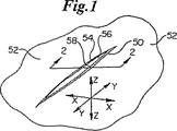
図1〜3において、例えば外科的切開又は創傷によって形成され得る皮膚52の表面における典型的な開口部50が示されている。図1に示したように、本発明の説明において、開口部50は、y−y軸と平行な長さすなわち長手方向と、x−x軸と平行な幅方向と、z−z軸と平行な深さ方向とを有するものとして表すことができる。本発明において、x−y−z軸は、皮膚52が外面である場合における外側組織面に関して画成される。本発明に関しては、垂直及び水平平面方向の表現は、当該開口部における外側組織面に対して用いる。開口部50の各側部によって形成される垂直内面60は、概ね、垂直境界面51に沿って対向するように見られる。曲線状の組織面に延在する開口部の場合には、開口部に関する対応する水平面及び垂直面は、かかる曲線状の組織面に関して画成されるものとする。また、例えば傾斜切開により開口部50が形成された場合等においては、垂直境界面51は、組織面に関する1つの方向のみにおいて垂直であり得るものとする。
1-3, a
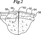
図2、3の断面図に最も良く示されているように、ヒトの皮膚52は通常、3つの明確な層を有している。これらの層は、外面55を有する主に非生存組織である表皮層54と、主に生存組織である真皮層56とと、皮下組織層58とを備えている。本発明の実施態様はヒト皮膚組織52に関して説明するが、本発明は筋膜、膜性臓器、血管、脈管構造、血管茎、植皮、膀胱等のような概ね画成された表面を有する他の種類の組織、並びに人工皮膚、人工膜、合成メッシュ等のような概ね画成された表面を有するその他の生物学的適合性材料における開口部の閉合にも適用可能であるものとする。
As best shown in the cross-sectional views of FIGS. 2 and 3, the
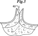
図3に拡大して示したように、皮膚開口部50の垂直境界面51の各側部における生存真皮層56の内面60が接合されて、いわゆる外返し状態で密着するときに、皮膚開口部は最小限の瘢痕化にて最も速く治癒すると、長らく周知されている。主に非生存組織である表皮層54が治癒開口部から除外できるかぎり、治癒の進行中に形成される瘢痕組織化の速度及び程度は向上する。
As shown in an enlarged view in FIG. 3, when the
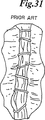
図30〜33を参照すると、本発明によって、より有効にかつ効果的に組織閉合を提供できることがわかる。図30〜33は、本発明の両側固定技術を使用して閉合された開口部と比較した、様々な先行技術の方法により閉合された皮膚開口部を示している。図30は、皮下縫合糸によって閉合された皮膚開口部を示している。外返しが過剰であるか又は不十分である場合、閉合開口部が概ね外返った状態によって、美しくない瘢痕を生じ得るとともに最適な治癒が得られなくなる可能性がある。図30からわかるように、縫目間の一貫性を得ることは困難で、閉合の質は外科医のスキルに負うところが大きい。図31は、従来の外科用ステープリングによって閉合された皮膚開口部を示している。閉合開口部が概ね美しくない外観を呈するだけでなく、ステープルの穴や開口部の過剰な外返し状態によって、望ましくない瘢痕を生じ得る。また、非再吸収性ステープルを使用した場合、完全に治癒がなされる前にステープルを取り外さなければならない。図32は、例えば米国特許第5,292,326号、第5,389,102号、第5,489,287号、第5,573,541号に記載のSQS機器として知られる交互嵌合式皮内ステープラによって閉合された開口部を示している。皮膚を重なり合わせ交互嵌合させることによって生じた特徴的な波状の外観から、治癒開口部において独特な形状の瘢痕が生じ得る。また、皮膚を重なり合わせ交互嵌合させることによって表皮組織が真皮層間に入り込む可能性があるので、結果として治癒が不完全になったり瘢痕が過剰となる。 Referring to FIGS. 30-33, it can be seen that the present invention can provide tissue closure more effectively and effectively. FIGS. 30-33 show skin openings closed by various prior art methods compared to openings closed using the bilateral fixation technique of the present invention. FIG. 30 shows the skin opening closed by a subcutaneous suture. If the inversion is excessive or inadequate, the closed opening of the closure may generally cause unsatisfactory scarring and may not provide optimal healing. As can be seen from FIG. 30, it is difficult to achieve consistency between stitches, and the quality of the closure is largely dependent on the skill of the surgeon. FIG. 31 shows a skin opening closed by conventional surgical stapling. Not only does the closed opening have a generally unaesthetic appearance, but excessive scarring of the staple holes and openings can cause undesirable scarring. Also, if non-resorbable staples are used, the staples must be removed before complete healing. FIG. 32 shows an interfitting type skin known as an SQS device described in, for example, US Pat. Nos. 5,292,326, 5,389,102, 5,489,287, and 5,573,541. The opening part closed by the inner stapler is shown. The characteristic wavy appearance created by overlapping and interdigitating the skin can result in a uniquely shaped scar in the healing opening. In addition, the skin layers can overlap and interdigitate so that epidermal tissue can penetrate between the dermis layers, resulting in incomplete healing and excessive scarring.
比較として、図33に本発明の方法と機器を使用して部分的に閉合された開口部が示してある。図示したように、開口部の閉合部分は、しっかりと閉合されており、かつ開口部の過度の外返しがない平坦な状態にあるので、最小限の瘢痕にてより良好な治癒が得られる。閉合部における留め具間の一貫性も得られる。留め具は皮膚面下に位置決めされるので(すなわち表皮下)、留め具は露出せず、また感染症や正常な治癒進行への障害が生じる可能性を高め得る、表皮の穿刺やボタンホールは存在しない。また、生体再吸収性材料、生体吸収性材料、更には生体侵食性材料から構成される留め具を使用した場合、後に留め具を取り外す必要がない。 As a comparison, FIG. 33 shows an opening partially closed using the method and apparatus of the present invention. As shown, the closed portion of the opening is tightly closed and is in a flat state without excessive reversal of the opening, resulting in better healing with minimal scarring. Consistency between fasteners at the closure is also obtained. Because the fasteners are positioned below the skin (ie, under the skin), the fasteners are not exposed, and epicutaneous punctures and buttonholes can increase the likelihood of infection and impairment of normal healing progress. not exist. Further, when a fastener composed of a bioresorbable material, a bioabsorbable material, or a bioerodible material is used, it is not necessary to remove the fastener later.
本発明の利点は、好ましくは生体再吸収性材料から構成される留め具によって皮膚開口部50の各側部の対象組織領域70を両側に係合させる機器及び方法によって実施される。本発明に関して使用される「両側の」という用語は、開口部50の垂直境界面51のそれぞれの側部上にあって、留め具が挿入される少なくとも2本の軸の存在を意味する。両側係合は、同時に又は連続的に行うことができる。使用される留め具は、様々な構成を有することが可能で、更に後述するように様々な方法で配置することができる。本発明の機器に対する留め具及び真皮層の位置、配列、方向はすべて、開口部を効果的に閉合するために真皮層の最適な密着と圧縮を得る上で、重要な事項である。皮膚開口部50については単一の組織片における開口部に関して説明するが、開口部50は、2つの別個もしくは接続していない組織片の間にできたものであってもよく、更には組織片とその組織片に固定された生物学的適合性材料片との間にできたものであってもよいものとする。
The advantages of the present invention are implemented by an apparatus and method that engages the
図4、5に示したように、垂直境界面51の両側には、最適な標的組織領域70が存在し、治癒のための最適な真皮の接触を達成するために、これを留め具が両側で係合させることができる。この対象組織領域70は、真皮層56内に位置し、図4に最も良く示されているように、組織が弛緩状態にあるとき長方形の断面領域として見られる。また、対象組織領域70内には、組織係合に関して最も好ましい領域72が存在する。深さ方向において、対象組織領域70は、表皮層54の表面55の下方約0.1 mmにある距離L3と、表面55の下方最大2.0 mmにある距離L4との間に位置する。最も好ましい領域72は、この表面の下方約0.2 mmにある距離L5と、この表面の下方約0.8 mmにある距離L6との間に位置する。幅方向において、対象組織領域70は、垂直境界面51から約1.0 mmにある距離L7と、垂直境界面51から約20.0 mmにある距離L8との間に位置する。最も好ましい領域72は、垂直境界面51から約2.0 mmにある距離L9と、垂直境界面51から約8.0 mmにある距離L10との間に位置する。対象組織領域70は執刀医には見えないので、マニピュレータアッセンブリ400とアプリケータアッセンブリ100は、執刀医が留め具400を配備させるために対象組織領域70を一貫して繰り返し位置決めすることができるよう設計することが好ましい。
As shown in FIGS. 4 and 5, there is an optimal
図6に示すように、皮膚組織には固有の柔軟性と弾性があるため、皮膚開口部が外返しになる際に留め具400を対象組織領域70内に配備することが最も望ましい。開口部50の両側部上の外返しになった真皮層56を留め具400に押し込むことによって、図4に示したように、外返し圧力が除去されて皮膚が弛緩して平坦状態になった後、真皮層56は留め具400によって両側に密着した状態に保持される。
As shown in FIG. 6, since skin tissue has inherent flexibility and elasticity, it is most desirable to deploy a
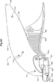
本発明の機器に関する実施態様は、図7〜20に示されている。通常、機器は、アプリケータアッセンブリ100と、組織マニピュレータアッセンブリ300と、留め具400とを含んでいる。
Embodiments relating to the device of the present invention are shown in FIGS. The instrument typically includes an
アプリケータアッセンブリ100の実施態様は、図7〜16に示されている。このアッセンブリは通常、上ハンドル部110と、ドライビングヘッド140が取り付けられている下ハンドル部120とを備えている。ユーザが機構を作動できるよう、ピボット202を中心として旋回するトリガ200が設けられている。手動旋回式トリガ機構200が図示されているが、アプリケータアッセンブリ100においては、様々なその他のユーザ作動式の手動トリガ、ボタン、又はアクチュエータ機構を使用することができるものとする。例として、プッシュボタン、スライド機構、カム機構、ばね作動式機器、ケーブル作動式プル機構、回転機構、又はタブ作動式トリガ等が挙げられる。この他、アプリケータ100を操作するために、電子式トリガ、空気式トリガ、動作制御式トリガ、遠隔操作式トリガ、又はコンピュータ駆動式トリガの形態をとる自動アクチュエータを使用することもできる。
An embodiment of the
図8〜13は、ドライビングヘッド140及び下ハンドル部120の実施態様を詳細に示した図である。ドライビングヘッド140は、好ましくはU字型であって、横材146によってバッキング部144から分離されたアンビル部142を有し、これによりギャップ148が形成される。横材146は凹状領域150を有することが好ましい。この凹状領域150は、組織マニピュレータアッセンブリ300の組織マニピュレータ面318に対応した形状をなすので、更に後述するように皮膚の真皮層56がギャップ148内に押し込まれて密着して、垂直境界面51の両側部上にあって捕捉される対象組織領域70が位置決めされる。ドライビングヘッド140は、下ハンドル部120と上ハンドル部110とに対して固定位に図示されているが、ドライビングヘッド140は、ドライビングヘッド140の操作性と方向性を高めるために、垂直境界面51の平面内で分節結合しても、或いは垂直境界面51の平面と垂直の方向に分節結合してもよいものとする。この他、下ハンドル部120を上ハンドル部110に分節結合してもよいし、或いは下ハンドル部120とドライビングヘッド140との両者を分節結合してもよい。
8 to 13 are views showing in detail the embodiment of the driving
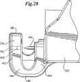
ドライビングヘッド140のアンビル部144にはアパーチャ152が貫通するように形成されている。アパーチャ152は、ペネトレータすなわちパイロットニードル154、156を摺動して収容できるよう適切な寸法で設けられており、アンビル部144の材料に直接穿孔して設けてもよいし、アンビル部144の穴に挿入された金属注入管等で裏打ちしてもよい。パイロットニードル154、156は、遠位部155、157全体に渡って概ね弓状の断面を有し、近位部159、161において中空でない円筒形の断面を有する。各遠位部155、157は、留め具400を収容し保持するための内側凹状面158、160を有する。各近位部159、161が留め具400の背面と係合することによって、留め具はニードルとともに遠位方向に進むことが可能になる。パイロットニードル154、156の遠位先端部162、164は、皮膚を貫通する鋭くとがった先を有する。パイロットニードル154、156は、アンビル部142の上面166下方の距離d1位置に垂直に配置されている。パイロットニードル154、156が対象組織領域70内に位置しているかどうか目視で確認するため、上面166を基準面として使用可能なことが好ましい。したがって、上面166と外側皮膚面とを位置合わせした際に、パイロットニードル154、156が対象組織領域70内に位置するように、最も好ましくは最も好ましい領域72内に位置するようにするため、距離d1の長さは0.1 mm〜2.0mmであることが好ましく、0.2 mm〜0.8mmであることが最も好ましい。
An
送出機構128は、ドライビングヘッド140から留め具を排出するためのものである。スライドブロック122は、下ハンドル部120内においてガイド124、126に摺動可能に取り付けられることが好ましい。トリガの作動によってスライドブロック122の摺動運動が引き起こされるように、スライドブロック122はトリガ200と係合する。パイロットニードル154、156は、スライドブロック122に固定して取り付けられ、スロット168を通ってドライビングヘッド140のバッキング部144から外側に延びる。したがって、スライドブロック122の前後摺動運動によって、パイロットニードル154、156は、スロット168、ギャップ148、アパーチャ152から延びたり後退したりする。パイロットニードル154、156に、又は直接留め具400に必要な力を与えるためには、いずれの数の機械駆動機構を使用してもよいものとする。例としては、摺動機構、カム機構、ばね作動式機構、ねじ伝動、空気式伝動、自動動作制御伝動等が挙げられる。
The
ドライビングヘッドが固定される皮膚開口部内に置かれて、皮膚開口部がパイロットニードル間の略中間点に位置合わせされたときにパイロットニードルが対象組織領域70の幅方向内に位置するよう、パイロットニードル154、156は、好ましくは約2.0 mm〜20 mm、最も好ましくは約4.0 mm〜16.0 mmのニードル間隔分だけ間隔をあけることが好ましい。
The pilot needle is positioned within the skin opening to which the driving head is fixed, and the pilot needle is positioned within the width direction of the
単一の留め具をパイロットニードル154、156の間に1つずつ手動で挿入することができるが、図14〜16の模式図に示したように、アプリケータアッセンブリ100の他の実施態様は、自動留め具送出格納機構220を有している。この機構においては、留め具は案内部材224を取り囲むように梯形状に垂直に積み重ね、ばね等の弾性部材(図示せず)によって下方に偏向させることが好ましい。機構を保護するためにハウジング222が設けられている。一連の梯形状留め具のうち最下部の留め具は、パイロットニードル154、156と係合する。各留め具400が前述したようにアプリケータアッセンブリ100の動作によって皮膚内に置かれると、スライドブロック122は道程の近位限界まで復帰し、一連の梯形状留め具が下方に偏向することによって、直ちに垂直方向に隣接した留め具が下方に移動し、パイロットニードル154、156と係合する。このとき、次の留め具が皮膚内に置かれて処置を繰り返すことができる。この場合も、本発明の文脈内で、複数の留め具を設けて配備するために、多数の配列や構成を使用することができることがわかるであろう。例としては、留め具400に関する水平方向、垂直方向いずれかにおける直列積付け、並列積付け、円形室,格納庫,保持ベルトを介した回転構造、又はテープ付着型形態等が挙げられる。
Although a single fastener can be manually inserted between the pilot needles 154, 156 one by one, as shown in the schematic diagrams of FIGS. 14-16, other embodiments of the
図17、18は、本発明の組織マニピュレータアッセンブリ300の実施態様を示している。アーム302、304の近位先端部307は、支点306において接続し、アッセンブリ全体がピンセット状構造に形成されている。各アームには握り領域312が設けられているので、アッセンブリを手指で握ることができる。図示したリベット316を含めて、支点306の部分に何らかの適切な固定法を使用してもよく、或いはアーム302、304を溶接しても鋳造しても一体成形してもよく、或いは一体的に形成してもよい。アーム302、304の材料及び全寸は、アームを手指で内側に弾性的に押すことができ、かつ圧力が除去された際に原位置に復帰するための記憶特性を有するように選択する。また、アーム及びアッセンブリの他の部分に使用される材料は、熱手段、化学手段のいずれを用いても殺菌が行えるよう、熱的にも化学的にも安定していることが好ましい。アーム302、304の好ましい材料は、ステンレス鋼である。
17 and 18 illustrate an embodiment of the
各アーム302、304の遠位先端部309には、組織マニピュレータ面318が形成されている。マニピュレータ面318は、図示のように半円筒形であって、各半円筒の径寸がアプリケータアッセンブリ100の凹状領域150の寸法及び形状に適合するよう選択することが好ましい。皮膚を保持する顎部材314は、各アーム部材302、304の外面326に取り付けることが好ましい。各顎部材314は、アームに取り付けるためのバッキング部324、並びにマニピュレータ面318の両側に配置された一対の内向き突起320を有する。より良好に皮膚を保持するため、各突起320の最内側縁には直接対向する鋸歯状の縁322を設けることが好ましい。バッキング部材324は、図示したように、リベット316等の機械留め具を含む適切な取付け法を用いて各アーム302、304に取り付けることができる。理由は後述するが、アーム302、304に加えられる適度な手指圧力の下で内向き突起320が皮膚マニピュレータ面318から離れて偏向することができるよう、各顎部材314は十分弾力性があることが好ましい。これは、顎部材314に使用される材料、バッキング部材324の厚さ寸法、及び内向き突起320とアームの遠位先端部309に最も近い留め具316との間にある各バッキング部材324のフリーレングスL1を調整して選択することによって達成することができる。バッキング部材324の設計においては、第一の力によって顎部材314を組織に係合させ、第一の力より大きい第二の力によってマニピュレータ面318を顎部材314間にある組織に係合させることを目的とする。また、垂直境界面51の各側部において一対の内向き突起320を使用することによって、側面に沿って一対の突起320間にある組織を安定させることができる。
A
アプリケータアッセンブリ100のギャップ148と凹状部150との中に組織が最適に近接することを確実にするために必要な圧力を上回る圧力がマニピュレータ面318を通して伝送されることを防ぐために、メカニカルストップ330が設けられている。メカニカルストップ330は、マニピュレータ面318がパイロットニードル154、156のニードル間隔から0.2〜0.8ミリメータ分だけ間隙を介した距離まで閉じるように、またメカニカルストップ330間の合計距離が、パイロットニードル154、156間のニードル間隔より0.4〜1.6ミリメータ大きくなるように設定することが好ましい。ニードル間隔が3.25ミリメータに設定されている実施態様において、メカニカルストップ330は、組織をギャップ148内に近接させた際にマニピュレータ面318を3.65〜4.85ミリメータの範囲まで閉じることが可能である。顎部材314はいずれの適切な材料で形成してもよいが、好ましい材料はステンレス鋼である。
図19、20は、本発明の留め具400の実施態様を示している。留め具400は、本体部402を有する。本体部402は、一対のフォーク材或いは脚406に接続する横材408を備えている。各脚406の前小口410は、パイロットニードル154、156の内側凹状面158、160に対応した寸法と形状を有するので、留め具400は図12、13に最も良く示したようにニードルの遠位部155、157間に収まりかつ摺動することが可能である。肩414は、パイロットニードル154、156の近位部159、161の安定した円筒形の断面に係合することによって、留め具400がニードルの動きによって遠位方向に前進できるように設けられることが好ましい。各脚406の遠位先端部412は、皮膚の開口部を簡単に通過できるよう内屈した形状をなしている。この皮膚の開口部はスカイビングと呼ばれるもので、パイロットニードル154、156によって形成される。いったん位置決めされた留め具が後退しないようにするため、各脚406には内向き返し404を設けることが好ましい。
19 and 20 show an embodiment of the
図19、20に示したように、留め具400の形状は全体としてU字型が好ましいが、両側組織係合を実施可能な他の形状も可能であり本発明の範囲内である。かかる他の形状には例えば、一般のステープルと同様の正方形、横材408が曲がりやその他の特徴を有する半円形、C字型、V字型、W字型等があるが、これらの限りではない。留め具400の形状は、平面構造において概ね画成されるが、その他の非平面的な形状や構造を使用することも可能であるものとする。例えば各脚406に複数の突起を有する留め具であって各突起が異なる平面に配向されている留め具や、留め具400の基準平面から突出するV字型に配置された横材408を有する留め具を使用することもできる。脚部材406は2本であることが好ましいが、例えば留め具の各側部の脚部材が二つ又構造又は三つ又構造を形成するように、追加の脚部材406を留め具400と同じ平面又は異なる平面に追加することも可能であるものとする。
As shown in FIGS. 19 and 20, the overall shape of the
図39に示したように、内側断面領域409は、圧縮された真皮組織を捕捉する留め具400によって画成される。一実施態様において、内側断面領域409は1.5平方mm〜50平方mmの範囲にあり、最も好ましくは5平方mm〜10平方mmの範囲にある。この領域は、1.5 mm〜9 mm、最も好ましくは約3.8 mmの内径長さと、1 mm〜5 mm、最も好ましくは約2 mmの内径幅によって概ね画成される。断面領域409の形状及び構造については、多くの形状及び構造を使用可能であることが明らかであろう。内側断面領域409は、返し412が配置された概ね矢じり形であることが好ましい。後述するように、返し412或いは同様の逆転止め突起は、留め具400の後退を防ぐ。返し412は内側断面領域409方向に向くことが好ましいが、返し412は省略してもよく、或いは外側に向いていてもよい。
As shown in FIG. 39, the inner cross-sectional area 409 is defined by a
送出・適用中に留め具400が変形する可能性があるが、好ましくは少なくとも10日間、設計領域の±30%の範囲内で断面領域409の寸法無欠性が保たれるよう、断面領域409内に保持される真皮組織の大部分が十分堅固な留め具400によって圧縮された状態で捕捉されていることが好ましい。留め具400の構造無欠性は、少なくとも21日間維持されることが最も好ましい。このようにして、留め具400内に捕捉された真皮組織は、治癒進行中に何ら張力を受けることなく生物学的治癒進行を可能にするのに十分な期間、圧縮された状態に保たれる。留め具400の寸法とアプリケータアッセンブリ100の動作とを調整して、内側断面領域409内の真皮組織の圧縮比を1より大きくすることが好ましい。圧縮比は、面積比又は幅比のいずれかとして画成される。幅の場合、圧縮比は、真皮組織が弛緩状態にあるとき、留め具400によって保持される垂直境界面に対するスカイビングの位置で割った、垂直境界面51に対するスカイビングの位置によって画成される寸法の比率である。面積の場合、圧縮比は、真皮組織が弛緩状態にあるとき、実際の断面領域409で割った、留め具400によって保持される真皮組織の面積の比率である。
The
この他、本発明に記載のとおり、変形可能な留め具によって組織対象領域内において両側組織固定を利用することも可能である。この場合、生体再吸収性留め具又は生体吸収性留め具の変形は少なくとも部分的に真皮組織の圧縮に寄与するので、機械組織マニピュレータの必要性は低減するか又は潜在的になくなる。本実施態様において、生体再吸収性留め具又は生体吸収性留め具は、真皮組織を適切に圧縮するためアプリケータ機器によって変形される。生体再吸収性留め具又は生体吸収性留め具の変形は、多くの方法によって実施することができる。例えば、アプリケータによる機械的支援を使用する又は使用せずに留め具に圧縮応力を与えて開構造にしてから留め具を閉構造に復帰させる方法、原位置で留め具の形状を変形させるか又は原位置で留め具内の圧力の低減又は緩和を行うために超音波、熱、又は光エネルギーを適用する方法、留め具の配備時に材料が破砕することなく変形可能であるような適切な形状と組成を有する高分子材料の設計、その他これらの技術の組合せなどが挙げられる。 In addition, as described in the present invention, it is also possible to utilize bilateral tissue fixation within the tissue target region with a deformable fastener. In this case, the need for mechanical tissue manipulators is reduced or potentially eliminated, since bioresorbable fasteners or deformations of bioabsorbable fasteners at least partially contribute to compression of the dermal tissue. In this embodiment, the bioresorbable fastener or bioabsorbable fastener is deformed by an applicator device to properly compress the dermal tissue. The bioresorbable fastener or the deformation of the bioabsorbable fastener can be implemented in a number of ways. For example, with or without mechanical support by the applicator, applying a compressive stress to the fastener to make it open, and then returning the fastener to the closed structure, whether the shape of the fastener is deformed in situ Or a method of applying ultrasound, heat, or light energy to reduce or alleviate the pressure in the fastener in situ, or a suitable shape so that the material can be deformed without breaking when the fastener is deployed And the design of a polymer material having a composition, and a combination of these techniques.
留め具400は、適切な生物分解性材料で形成されることが好ましい。現在最も好ましい生物分解性材料は、ラクチド/グリコライド共重合体である。この共重合体における比率は、各成分が少なくとも10%を下回らず、ラクチドが60%〜70%の範囲にあることが好ましい。他の適切な材料としては、ポリ(DL−ラクチド)、ポリ(L−ラクチド)、ポリグリコライド、ポリ(ジオキサノン)、ポリ(グリコライド−コ−トリメチレンカーボネート)、ポリ(L−ラクチド−コ−グリコライド)、ポリ(DL−ラクチド−コ−グリコライド)、ポリ(L−ラクチド−コ−DL−ラクチド)、ポリ(グリコライド−コ−トリメチレンカーボネート−コ−ジオキサノン)等が挙げられる。また、この他の適切な材料としては、コラーゲンやエラスチンなどのような天然型生重合体を有する組成物、或いは非吸収性留め具の場合にはステンレス鋼、金属、ナイロン、その他生物学的適合性物質、或いは留め具の望ましい適用や性能に応じたかかる材料の様々な組合せ等が挙げられる。
The
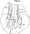
ここで、図21〜24を参照して、本発明の機器の動作を説明する。図12に示したように、留め具400は最初にパイロットニードル154、156の間に装填される。次に、パイロットニードル154、156と留め具400とが完全にスロット168内に入るよう、スライドブロック122を極限まで近位方向に後退させる。次にドライビングヘッド140が皮膚開口部50内に案内され、図21に示すように、上面282が皮膚の外面と位置合わせされる。組織マニピュレータアッセンブリ300の顎部材314は、ドライビングヘッド140の両側に置かれる。図22に示したように、顎314が皮膚面に係合して皮膚52をアプリケータアッセンブリ100のギャップ148に押し込むよう、マニピュレータアッセンブリ300のアーム302、304は内側に押される。鋸歯状の縁322によって、皮膚面が保持されるとともに、皮膚が顎から側方に外れることが防止される。内向き圧力が更にアーム302、304に加えられると、内向き突起320はアンビル部142の側部170及びバッキング部144の側部172に係合する。図23に示したように、内向き突起320間には、それぞれ捕捉された皮膚が一層ずつみられる。図24に示したように、内向き圧力が更にアーム302、304に加えられると、組織マニピュレータ面は顎314から若干内側に偏向し、各組織マニピュレータ面は横材146の凹状領域150に係合し組織マニピュレータ面の間にはそれぞれ捕捉された皮膚が一層ずつ存在する。この状態において、真皮層56の内面60はギャップ148内において互いに直接密着し、垂直境界面51に対してほぼ平行状態にあるが、重なり合い又は交互嵌合の状態にはない。
Here, the operation of the device of the present invention will be described with reference to FIGS. As shown in FIG. 12, the
本実施態様において、パイロットニードル154、156は、概ね水平状態でかつ皮膚の外面に対してほぼ平行状態に位置合わせされ、対象組織領域70内に置かれる。留め具400の横材408は、垂直境界面51を概ね横断するよう位置決めされる。横材408と脚406によって画成される留め具400の作用面は、概ね水平方向である。次にトリガ280が作動されることにより、下ハンドル部120内においてスライドブロック122が近位方向に移動し、パイロットニードル154、156が皮膚内に進入し、垂直境界面51の各側部上の皮膚の対象組織領域70にスカイビングが形成される。留め具400はパイロットニードル154、15とともに移動し、留め具400の各脚406が同時にスカイビングに挿入される。いったん留め具400が十分な距離だけ遠位方向に前進して、留め具400の返しチップ416がアパーチャ152に入りスカイビングから脱出すると、トリガ280が逆動され、スライドブロック122は近位方向に移動してパイロットニードル154、156を後退させる。返し412は皮膚と係合するので、留め具400がパイロットニードルとともに後退することは防止される。スライドブロック122が近位方向に完全に後退することによって、パイロットニードル154、15はギャップ148から完全に後退し、マニピュレータアッセンブリ300上の圧力は解放され、アプリケータアッセンブリ100は開口部50内において近位方向に移動して別の留め具400を送出することも可能であるし、或いは開口部50から取り外されることも可能である。
In this embodiment, the pilot needles 154, 156 are positioned in the
留め具の脚が皮膚開口部の各側部上の対象組織領域に同時に挿入され、留め具の脚が表皮皮膚面に平行に方向付けられることを特徴とする上記の機器の実施態様の他に、当業者は、皮膚組織の開口部に関する機械固定システムのこの他の実施態様が本発明の範囲内であることがわかるであろう。例えば、横材408と脚406によって画成される留め具400の作用面は、少なくとも1つの方向において、表皮層54の外面55によって概ね画成される水平平面に対して概ね垂直又は斜めに方向付けることもできる。かかる実施態様においては、留め具400は概ね垂直方向に挿入され、脚406は上向き方向又は下向き方向に概ね方向付けされることが可能である。
In addition to the device embodiment described above, wherein the fastener legs are simultaneously inserted into the target tissue region on each side of the skin opening, and the fastener legs are oriented parallel to the epidermal skin surface. Those skilled in the art will appreciate that other embodiments of a mechanical fixation system for an opening in skin tissue are within the scope of the present invention. For example, the working surface of the
図25〜29には、留め具が両側対象組織領域に連続的に挿入されることを特徴とする本発明の機器の他の実施態様が示されている。一実施態様において、留め具500は、遠位先端部505における返し506と、近位先端部503における取付けフラップ504とを備えた柔軟な本体部502を有する。柔軟な本体部502は、パイロットニードル154、156の凹状内面158、160内に収まるような寸法で設ける。取付けフラップ504にはスロット508が貫通形成されており、スロット508は返し506を収容するのに適している。アプリケータアッセンブリ100において、各アパーチャの領域のみがパイロットニードル154、156の弓状断面を通過させ得るべく十分開口しているように、アンビル部142は、アパーチャ152間に形成されて各アパーチャ152の部分内に延びる凹状デフレクタ153を有する。図1〜29に示したように、操作において、留め具500は軸方向にパイロットニードル154と位置合わせされ、ニードルの対応する凹状内面内に挿入され、返し506はニードルの先端方向に向けられる。このとき、アプリケータアッセンブリ100は前述のように皮膚開口部50の境界面部51に案内される。このとき、前述のように組織マニピュレータアッセンブリ300が適用されて、真皮層56はギャップ148内に密着する。これにより、対象組織領域70は適切に位置決めされる。スライドブロック122とそれに取り付けられているパイロットニードル154、156がトリガ280の作動によって遠位方向に移動すると、留め具500は皮膚組織を通って、留め具500が配置されているパイロットニードル154とともに皮膚開口部50の一方の側部上に向けて前進する。ただし、いったん返し506のチップがアパーチャ152に到達すると、かかるチップは凹状デフレクタ163と係合して凹状デフレクタ163に沿って側方に摺動を開始するので、柔軟な本体部502は屈曲する。パイロットニードル154、156が更に前進すると、返し506は、デフレクタ163によって180度回転する。返し506が、返し506を反対方向に転換させるのに十分な距離だけ離してパイロットニードル154の前に位置決めしてもよいし、或いは、アパーチャ152への進入時における返し506の方向転換が十分に返し506を反対方向に転換させるような深さまで、パイロットニードル154が対応するアパーチャ152内に進入してもよい。いったん第二のスカイビングに沿って方向転換と位置決めがなされると、パイロットニードル156の後退に伴って、返し506はパイロットニードル156によって反対方向に進み、皮膚組織を通って垂直境界面51の側部に向けて前進する。いったん返し506が皮層から脱出すると、取付けフラップ504が屈曲するので、返し506はスロット508に挿入可能になる。したがって、留め具500はループ状に固定され、皮膚開口部50の両側部は相互に捕捉される。取付けフラップ504の代わりに、縫合糸を縫い付ける柔軟な本体502上の適切な構造を用いてもよい。このとき、縫合ロックを使用して縫合糸を返し506に固定して両側捕捉を行う。以上に記載の本実施態様においては、複数のスカイビングが同時に形成され、留め具400が反対方向からそれぞれの対応するスカイビングに連続的に挿入される。この他、パイロットニードル154、156のかわりにU字型ニードルを使用して、スカイビングを形成して留め具を連続挿入することも可能である。スカイビングの両側形成と留め具の挿入に関する多くのその他の組合せは、本発明の範囲で検討される。
Figures 25-29 show another embodiment of the device of the invention characterized in that the fasteners are inserted continuously into the bilateral target tissue regions. In one embodiment, the
前述したように、留め具500の柔軟な本体502によって画成される作用面が、表皮層54の外面55によって概ね画成される平面とほぼ平行でかつ垂直境界面51を横断するように、留め具は方向付けられる。ただし、当業者は、留め具500の作業面は、外面55によって概ね画成される平面に対してほぼ垂直又は斜めに方向付けすることも可能であることがわかるであろう。このとき、垂直境界面51に対しては横断方向に留まるものとする。また、当業者は、対象組織領域が連続的に留め具によって貫通されることを特徴とするこの他の両側捕捉機械固定システムも本発明の範囲内で可能であることがわかるであろう。例えば、留め具に回転運動を与える機構を使用して、半円形、楕円形、又は螺旋形の留め具を垂直境界面51の各側部上の対象組織領域70に連続的に進入させることができる。この場合、垂直境界面51全体に渡る皮膚の交互嵌合又は重なり合いはみられない。この機構は、半円形、楕円形、又は螺旋形のスカイビングを形成する手段を有してもよい。このスカイビングを通って、留め具は前進することができる。或いは、留め具自体が十分強固な材料で形成されかつ鋭利な先を有するように構成することによって、留め具自体が皮膚を通過する際にスカイビングを形成することができるようにしてもよい。連続的両側捕捉運動を提供する他の実施態様において、2本の脚に接続する横材を有する留め具が提供される。この実施態様においては、留め具が直線的に皮膚に進入する際に一方の脚がもう一方の脚の前に来るよう、脚の寸法に差異がある。更に他の実施態様においては、皮膚と係合する返しを有する軸部を備えた2つのまっすぐな留め具が提供される。これらの留め具は垂直境界面51の両側部上で反対方向を向き、可逆的な運動を可能にするアプリケータアッセンブリによってそれぞれのスカイビングを通って連続的に前進する。
As described above, the working surface defined by the
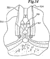
図34に示したように、一実施態様において、タブ又はその他の同様な案内構造167がアンビル部140の露出部から突出して、かかる案内構造に基づいて皮膚の外面を配置する上での基準案内として働く。最も好ましくは、この案内構造167を組織マニピュレータアッセンブリ300のアーム302、304の内面にある対応する一対の面案内機構169と係合するように調整することによって、組織開口部50の垂直境界面51に対してアプリケータ100と組織マニピュレータ300が適切に位置決めされているかどうか触覚と目視で確認することができるようにする。案内構造167と案内機構169が協働することによって、アプリケータ100が垂直境界面51を中心として側面に沿って維持され、水平方向にも垂直方向にも適切に位置決めされ続けることが好ましい。この他、ユーザがアプリケータアッセンブリ100と組織マニピュレータアッセンブリ300とを適切に位置決めすることを支援するために、ドライビングヘッド140の外側辺りに目視用標識及び/又は外側プラットフォーム状構造を設けてもよい。
As shown in FIG. 34, in one embodiment, a tab or other
図35、36は、アプリケータアッセンブリ100と組織マニピュレータアッセンブリ300の他の実施態様を示している。この実施態様において、マニピュレータ面318と凹状領域150とのいずれもが半球形で、組織が組織マニピュレータ300によってアプリケータ100内に押し込まれる際に水平方向と垂直方向に案内する構造を提供する。本実施態様においては、ボール状チップ318への加圧によって組織に捕捉力及び圧縮力が与えられる際に組織を捕捉する内向き突起320はみられない。アプリケータ100の領域150は半球形で、ボール状チップ318と1つ以上の方向において係合するものであり、単に単一方向において組織を位置合わせする凹状領域というものではない。
FIGS. 35 and 36 show another embodiment of the
図37は、アプリケータアッセンブリ100の他の実施態様を示している。この実施態様において、留め具400は、垂直境界面51に沿った組織に斜めに挿入される。この実施態様において、貫通ニードル152、154は、水平に対して斜め下方を向いており、ドライビングヘッド140の距離d1は縮小されている。組織がドライビングヘッド140内に位置決めされるとき又はアプリケータアッセンブリ100が次の留め具400を挿入するために位置決めされるときに、上突起167は、開口部50の垂直境界面51の上面に達して案内として働き、上突起167とドライビングヘッド140との間にあるアパーチャ141は、垂直境界面51の平面内においてアプリケータアッセンブリ100の回転運動が少なくすむように位置決めされる。開口部50の垂直境界面51に沿って留め具400を斜め方向に挿入することの利点の1つは、隣接する留め具400のバッキング部材408間の有効間隔が縮小されることである。これにより、開口部50の長手方向距離当りでより多くの留め具を挿入することが可能になることによって、引裂きに耐えるために垂直境界面51全体に渡って加えることができる保持圧力を増大させる機会が得られる。
FIG. 37 shows another embodiment of the
図38は、本発明の他の実施態様を示している。この実施態様において、組織マニピュレータ300とアプリケータアッセンブリ100はともに片手式外科用器具600に組み込まれている。本実施態様において、まず、手動トリガ200を用いて組織マニピュレータアッセンブリ300のアーム302、304を側方に押す動作がなされる。次に、手動トリガ200は更に押し下げられて送出機構128と係合する。カム、楔、又は同様の機構の形態をとるハンドル110内部の力変換機構602が、トリガ200の押下げによってまず係合する。次にトリガ200を更に押し下げると、送出機構128が作動する。アプリケータアッセンブリ100の構造と組織マニピュレータアッセンブリ300の構造とを一体化させた片手式外科用器具600は、多くの方法で配置及び操作を行うことができることがわかるであろう。例えば、単一の2段階アクチュエータの代わりに2つのトリガアクチュエータを使用することができる。組織マニピュレータアッセンブリ300とアプリケータアッセンブリ100とを同一方向に直列で配置する代わりに、2つのアッセンブリ300、100を長手方向において対向するように配置することもできる。
FIG. 38 shows another embodiment of the present invention. In this embodiment, the
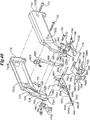
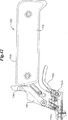
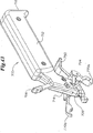
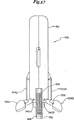
図40、41、42、43、44には、前述したボトムアップ法に対する方法として、トップダウン法を使用した手持ち式外科用器具700の他の実施態様が示されている。手持ち式外科用器具700は、ハンドルアッセンブリ702と、組織マニピュレータアッセンブリ704と、アプリケータアッセンブリ706とを備えている。ハンドルアッセンブリ702は、近位先端部708と遠位先端部710とを有する。ハンドルアッセンブリ702は、保持部712と取付け部714とを更に備えている。ハンドルアッセンブリ702は、第一のハンドル本体716と第二のハンドル本体718とを用いて構成することが好ましい。第一のハンドル本体716は、一対の中空突起720a、720bを含む。第二のハンドル本体718は、中空突起720a、720bと位置合わせされるよう位置決めされた一対の通り穴722a、722bを含む。また、第一のハンドル本体716は、第二のハンドル本体718に位置する通り穴725と位置合わせされる穴724を含む。第一のハンドル本体716は、第二のハンドル本体718の通り穴727と位置合わせされた別の穴726も含む。第一のハンドル本体716と第二のハンドル本体718は、最も一般的にはねじである固定手段721を用いて組み立てられてハンドルアッセンブリ702を構成する。固定手段727は、中空突起720aと通り穴722aとにおいて、並びに中空突起720bと通り穴722bとにおいて、並びに穴726と通り穴727とにおいて、第一のハンドル本体716と第二のハンドル本体718とを係合するために用いられる。第一のハンドル本体716と第二のハンドル本体718とのいずれも、取付け逃げ部730内に位置決めされる取付け穴728を含んでいる。取付け穴728と取付け逃げ部730は、ばねアッセンブリ731を収容する。第一のハンドル本体716と第二のハンドル本体718両方の近位先端部708には、一対の突起732a、732bが設けられている。突起732a、732bは、突起穴734a、734bを含む。第一のハンドル本体716と第二のハンドル本体718とのいずれも、取付け穴742と取付けピン743とを含む外側取付け面740を含む。
40, 41, 42, 43, and 44 show another embodiment of a hand-held
本実施態様における組織マニピュレータアッセンブリ704は、付勢先端部752と取付け先端部754とを有するトリガ750を備えることが好ましい。取付け先端部754は、取付けブロック756を含む。取付けブロック756は、円筒形溝760を有する取付け面758を含む。取付けブロック756は、取付け逃げ部762を更に備える。取付けブロック756内にはノッチ763も設けられている。一対の対向する取付け壁764a、764bは、取付け面758とともに取付け逃げ部762を画成する。一対の対向する支柱766a、766bは、取付け壁764a、764bに取り付けられている。また、取付け壁764a、764bの外側には、一対の穴768a、768bが設けられている。
The
組織マニピュレータアッセンブリ704は、一対の対向する組織整形部770a、770bを更に含む。組織整形部770bは、図45、46に更に詳細に示されている。組織整形部770aは組織整形部770bと同じ特徴を含むものとするが、両者は左右対称に構成されているものとする。組織整形部770bは、取付け先端部772と保持先端部774とを含む。取付け先端部772は一対の対向する位置合わせされた取付け穴778、778bを有する開口部776を含む。組織整形部770bは、取付け穴780と、支柱穴782と、限界穴784とを更に含む。限界ねじ786は、限界穴784に回転可能に挿入される。組織整形部770a、770bの外部には、案内突起788が設けられている。保持先端部774は、内面790と外面792とによって画成されている。内面790は、近位顎794と、遠位顎796と、弓状逃げ部798と、ボトムリップ800とによって更に画成されている。
アプリケータアッセンブリ706は、アプリケータトリガ802を含むことが好ましい。アプリケータトリガ802は、付勢先端部804と、駆動先端部806と、回転通り穴808とを含む。ねじとして示されている支点部材810は、通り穴725と、通り穴808と、穴724とに摺動挿入される。支点部材810は、アプリケータトリガ802の回転移動を可能にするとともに、第一のハンドル本体716と第二のハンドル本体718との間の固定強度を高める働きをなす。駆動先端部806は、チップ812を含む。アプリケータアッセンブリ706は、図47、48、49に更に詳細に示されている挿入ブロック814を更に含む。挿入ブロック814は、取付け先端部816と挿入先端部818とを含む。挿入ブロック814の上面には、中空チャネル820が設けられている。中空チャネル820の一方の側部上の一対の取付け穴822a、822bは、中空チャネル820のもう一方の側部上に位置決めされている一対の取付け穴824a、824bと位置合わせされる。また、挿入ブロック814は、一対の位置合わせ穴823a、823bも含む。この他、挿入ブロック814は回転支柱827を収容する別の一対の支柱穴825a、825bを含む。挿入先端部818は、挿入ヘッド826によって画成される。挿入ヘッド826の両側部には、弓状捕捉領域828a、828bが設けられている。挿入ヘッド826の両側部には単一の弓状捕捉領域828a、828bが図示されているが、挿入ヘッド826は両側部に複数の弓状捕捉領域を含んでもよいものとする。捕捉領域828a、828b内には、位置合わせ標識830が設けられている。位置合わせ標識は、穴又は水平レッジを含んでもよい。挿入キャビティ831と送出キャビティ832は、取付け先端部816から挿入先端部818まで延在する連続的開口部を画成する。取付けスライド833は、挿入キャビティ831と送出キャビティ832の中に収まる寸法で設けられる。取付けスライド833は、一対のキャビティ壁836a、836bによって画成される取付けキャビティ834を含む。挿入スライド838も、挿入キャビティ831と送出キャビティ832の内部に収まるような寸法で設けられる。挿入スライド838は、一対の貫通部材840a、840bを備える。貫通部材840a、840bはそれぞれ、内側弓状部842を含む。貫通部材840a、840bは、バックスパン844を介して接続される。
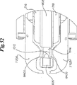
上記の外科用器具700は、単発設計である。この外科用器具700においては、単一の生体吸収性留め具1010が用いられる。この単一の生体吸収性留め具1010については、図50、51に示されている。また、更に詳細には、2003年6月25日に同時出願された米国特許出願「創傷閉合時に使用される動的生体吸収性留め具」に記載されている。かかる出願は、本出願と同一出願人によるもので、全体として本願に引用して援用している。図50に示したように、留め具1010は、一対のアーム1014a、1014bに動作可能に接続するバックスパン1012を備えている。図示のとおり、留め具1010は、バックスパン1012とアーム1014a、1014bとの全体に渡って一貫した径1013を有する。アーム1014a、1014bはそれぞれ、内側に突出したクリート1018a、1018bに接続する丸チップ1016a、1016bを含む。留め具1010は、外面1020と内面1022とを含む。バックスパン1012とアーム1014a、1014bとクリート1018a、1018bによって画成される内面1022は、内側組織捕捉領域1024を画成する。各クリート1018a、1018bは、挿入面1026と、クリートチップ1028と、背面1030とを含む。背面1030は、アーム1014a、1014bと交差し、捕捉領域1032a、1032bを画成する。留め具1010の各アーム1014a、1014bは、挿入幅1034を有する。この挿入幅1034は、アーム1014aとクリート1018a、又はアーム1014bとクリート1018bの全体に渡る最大幅として画成される。通常、留め具1010は貫通部材840a、840bとバックスパン844との間に収まる寸法で設けられる。留め具1010は、図52に示したように、アーム1014a、1014bが内側弓状部842内に収まるように位置決めされる。図51に示した留め具1010の他の実施態様においては、径1013はバックスパン1012とアーム1014a、1014bとの全体に渡って寸法を調整することが可能で、留め具1010と貫通部材840a、840bとの相互作用に影響を及ぼさずに望ましい強度を提供する。
The
外科用器具700は、皮層の両側固定のための全貫通両側組織固定技術860において使用することが好ましい。この全貫通両側固定技術860は、図57、58、59、60、61、62、63に示されている。全貫通手術については、皮膚創傷の閉合を参照して説明するが、当業者は、全貫通手術が筋膜、内蔵、血管、脈管構造等の組織開口部の閉合、又は皮膚移植、膀胱その他の解剖学的組織を含めた組織結合物を伴う組織開口部の閉合等のようなその他の用途においても効果的に適用可能であることがわかるであろう。
通常、全貫通両側固定技術860の第一段階は、留め具1010を貫通部材840a、840bとバックスパン844との間に装填することである。図53に示したように、留め具1010は、内側弓状部842内にぴったり収まる。図54に示したように、貫通部材840aと対応する貫通部材840bは、貫通断面862を有する。同様に、図55に示したように、クリート1018aと対応する1018bは、クリート断面864を有する。留め具1010は、挿入幅1034が貫通断面862を超えるように特に設計される。したがって、クリート1018a、1018bは、図53に示したように、貫通部材840a、貫通部材840bから内側に突出する。
Typically, the first step in the full through bilateral fixation technique 860 is to load the
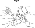
いったん留め具1010が外科用器具700に装填されると、挿入ヘッド826が一対の対向する側部864a、864bを有する組織創傷862内に挿入されて位置決めされる。外科用器具700は、図56に示したように開放配置866にあるべきである。この配置において、組織整形部770a、770bは、挿入ヘッド826からかなり間隔をあけた位置にある。図57に示したように、最も一般的には標準的な外科用ピンセットであるところの保持器具867を用いて、医師は対向する側部864a、864bを保持し、図58に示したように挿入ヘッド826に近接する対向する側部864a、864bを外返し配置869にする。このとき、対向する側部864aは、捕捉領域828a内に位置決めされ、一方対向する側部864bは、捕捉領域828b内に位置決めされる。位置合せ標識830を使用して、医師は図59に示したように対向する側部864a、864bを、捕捉領域828a、828bの垂直高さに対して適切に位置決めすることができる。適切に位置決めがなされると、対向する側部864a、864bである真皮層56は捕捉領域828a、828bの表面に密着する。
Once
対向する側部864a、864bが捕捉領域828a、828b内に適切に位置決めされた後、医師がトリガ750を上方に偏向させると、組織整形部770a、770bは、図60に示したように組織領域828a、828b内の対向する側部864a、864bを同時に保持する。外科用器具700は、捕捉配置871の状態になる。捕捉配置871は、トリガ750を上方に向けてトリガ750を回転支柱827を中心として回転させることによって完成される。回転支柱827は、支柱穴825a、825bと円筒状溝760と穴768a、768bと連結して、トリガ750と挿入ヘッド814とを動作可能に接続する。トリガ750が上方に偏向されると、取付け先端部754は下向きに弧を描くように移動するので、対向する支柱766a、766bは下方に移動し、組織整形部770a、770b上の案内突起788と密着する。これによって組織整形部770a、770bは取付けピン743を中心として下向きに回転し、組織整形部770a、770bの内面790は捕捉領域828a、828bに近接する。組織整形部770a、770bが下方に回転する際、内面790のボトムリップ800は、組織、特に弾力性のある真皮層56が捕捉領域828a、828bの底面から抜け出すことを防ぐ。挿入ヘッド826と組織整形部770a、770bとが精確な寸法で設けられているので、前述したように対象組織領域70は対向する側部864a、864bの内部に位置決めされる。また、組織整形部770a、770b上の近位顎794と遠位顎796の組合せは、対向する側部864a、864bを保持して引っ張るので、対向する側部864a、864bは挿入ヘッド826と組織整形部770a、770bとの間においてしっかりと保持され、図61に示したように、対向する側部864a、864bの表皮層54に穴が開く可能性が更に低減される。
After the opposing
いったん対向する側部864a、864bが挿入ヘッド826と組織整形部770a、770bとの間に保持されると、医師は図62に示したように、アプリケータトリガ802の付勢先端部804を遠位方向に向ける。付勢先端部804が後方に移動すると、トリガ802は支点部材810を中心として回転するので、駆動先端部806上のチップ812は近位方向に移動する。取付けキャビティ834内に位置決めされるチップ812は、キャビティ壁836aと密着するので、取付けスライド833は送出キャビティ832を通って近位方向に移動する。取付けスライド833は、挿入スライド838と接触するので、挿入スライド838も送出キャビティ832を通って近位方向に移動する。挿入スライド838が近位方向に移動すると、貫通部材840a、840bは送出キャビティ832から、捕捉領域828a、828b、対向する側部864a、864bの対象組織領域70、挿入キャビティ831へと順に進入する。貫通部材840a、840bが近位方向に前進すると、図52に示したように、留め具1010は送出キャビティ832から同時に出て、捕捉領域828a、828b、対向する側部864a、864bの対象組織領域70、挿入キャビティ831へと順に進入する。前述したように、挿入幅1034は、貫通断面862より大きい。したがって、貫通部材840a、840bによって対象組織領域70内で切削される穴は、挿入幅1034に対応するために伸張しなければならない。クリート1018a、1018bが対象組織領域70内で切削される穴に進入すると、真皮層56内の貫通部材840a、840bによって貫通された穴はクリートチップ1028を上回るように弾力的に伸張する。このとき真皮層56は反発して捕捉領域1032a、1032b内に弾力的にはまり込む。
Once the opposing
アプリケーションアッセンブリ706を使用して、医師がアプリケータトリガ802の付勢先端部804を近位方向に向けると、トリガ802は支点部材810を中心として回転するので、駆動先端部806上のチップ812は遠位方向に移動する。取付けキャビティ834内に位置決めされるチップ812は、キャビティ壁836bと密着するので、取付けスライド833は送出キャビティ832を通って遠位方向に移動する。取付けスライド833によって、挿入スライド838も近位方向に移動する。したがって、貫通部材840a、840bは、挿入キャビティ831、対象組織領域70、捕捉領域828a、828bから順に後退し、送出キャビティ832に進入する。ただし、留め具1010は対象組織領域70内に留まる。このときクリート1018a、1018bは、留め具1010が捕捉領域1032a、1032b内に弾力的に保持される捕捉真皮層によって後退させられことを防止する。留め具1010は、組織創傷862内に留まるので、バックスパン1012は対向する側部864a、864b間のギャップに架け渡され、真皮層56は強制的に近接されて生物学的治癒進行を促進する。いったん留め具1010が配置されると、医師はトリガ750を下方に向ける。したがって組織整形部770a、770bは上方に回転して対向する側部864a、864bを解放するので、外科用器具700は開放配置866に戻る。全貫通両側固定技術860は通常、組織創傷862の長さに沿って繰り返し施されて、結果として図63に示したように創傷862が閉合される。
Using the
図64〜68に、手持ち式外科用器具900の他の実施態様が示してある。手持ち式外科用器具900は、本体アッセンブリ902と、トリガアッセンブリ904と、組織操作アッセンブリ906と、アプリケータアッセンブリ908と、留め具アッセンブリ909とを備えている。本体アッセンブリ902は、複数の固定部材912を介して接続される成形ハウジング910を備えている。成形ハウジング910は、近位先端部914と遠位先端部916とを含む。成形ハウジング910は、底開口部918を更に含む。
FIGS. 64-68 illustrate another embodiment of a hand-held
トリガアッセンブリ904は、トリガ920と、操作穴924と、ラチェット部材925と、インタフェースチャネル926と、上面928とを備えている。上面928は、上係合部930を備えている。上係合部930は、ばねアッセンブリ932と連結する。
The
組織操作アッセンブリ906は、一対の連結アーム934a、934bと、一対の組織整形部936a、936bとを備えている。組織整形部936a、936bは、前述した組織整形部770a、770bと実質的に同様な保持部937を含む。組織整形部936a、936bの外面上には、前述した案内突起788と同様に機能する整形案内ランプ938が設けられている。各組織整形部936a、936bは、一対の取付け穴940a、940bを含む。
The
アプリケータアッセンブリ908は、回転部材944とレバー部材946とを備えた前進アッセンブリ942を含む。回転部材944は、一対の対向する回転素子948a、948bを備えている。各回転素子948a、948bは、遠位穴950と、支点穴952と、近位穴954とを含む。ここで、遠位コネクタ956を遠位穴950に通し、支点コネクタ958を支点穴952に通し、近位コネクタ960を近位穴954に通すことによって、回転素子948a、948bは相互接続される。レバー部材946は、遠位先端部962と近位先端部964とを含む。支点コネクタ958には、ばねアッセンブリ959が取り付けられている。遠位先端部962は、チャネル966を有する。レバー部材946は、支点コネクタ969を有する支点穴968を含む。近位先端部964には、連結チップ970が設けられている。アプリケータアッセンブリ908は、挿入スライド972を更に含む。挿入スライド972は、遠位先端部974と近位先端部976とを備えている。挿入スライド972の遠位先端部974には、一対の取付け壁980a、980bによって画成される取付けキャビティ978が設けられている。挿入スライド972の近位先端部976には、一対の対向する貫通部材982a、982bが設けられている。貫通部材982a、982bは、それぞれ内側弓状部984a、984bを含む。貫通部材982a、982bは、バックスパン部材986において動作可能に接続されている。アプリケータアッセンブリ908は、挿入ヘッド988を更に含む。挿入ヘッド988は、弓状捕捉領域990を含む。挿入ヘッド988の全長に渡って、挿入スライド972を収容するような寸法を有する挿入キャビティ992が設けられている。
Applicator assembly 908 includes an
本実施態様の留め具アッセンブリ909は、図50、51で前述した複数の生体吸収性留め具1010からなる留め具スタック994と、留め具ハウジング996と、ばね送りアッセンブリ998とを備えている。留め具アッセンブリ909は、着脱式ロッキング部材1000を更に含んでもよい。着脱式ロッキングピン1000が設けられていると、外科用器具900は完全に組み立てられた状態で発送されることが可能になるので、外科医が使用し易くなる。着脱式ロッキングピン1000は、発送中又は保管中にばね送りアッセンブリ998が留め具スタック994に直接力を加えることを防止することが好ましい。そうすれば、生体吸収性留め具1010がばね力を長期間受けても変形することがないからである。
The
外科用器具900は、前述した外科用器具700と同様な全貫通両側組織固定技術によって使用することが好ましい。手術上異なる点の1つは、外科用器具900が複数の留め具1010が予め装填されている複発設計であるので、個々の留め具1010を手動装填する必要がないことである。手術上異なるもう1つの点は、外科用器具900が、組織操作アッセンブリ906とアプリケータアッセンブリ908とを連続的に作動させる二段階機構を組み込んだトリガアッセンブリ904を含んでいる点である。
組織操作アッセンブリ906によって組織を保持するにあたり、医師が本体アッセンブリ902とトリガアッセンブリ904とを強く握ると、トリガ920がラチェット部材925を中心として回転する。トリガ920が底開口部918に入ると、連結アーム934a、934bは反対方向に回転して組織整形部936a、936b上の成形案内ランプ938に密着するので、組織整形部936a、936bは本体アッセンブリ902とともに、回転部材連結取付け穴940a、940bを中心として回転する。したがって、組織整形部936a、936bは、挿入ヘッド988の両側部の保持位置まで回転する。
When holding the tissue by the
組織整形部936a、936bを保持位置まで操作した後、本体アッセンブリ902とトリガアッセンブリ904とを引き続き強く握ると、トリガ920は底開口部918に更に挿入され、インタフェースチャネル926は遠位コネクタ956の方へ摺動する。トリガ920が底開口部918に更に挿入されると、遠位コネクタ956はインタフェースチャネル926の先端部に到達し、回転部材944は支点コネクタ958を中心として回転し、近位コネクタ960は下方に移動する。近位コネクタ960が下方に移動すると、チャネル966が下方に移動する。この結果、レバー部材946は支点コネクタ969を中心として回転する。チャネル966が下方に移動すると、近位先端部964は前方に移動する。したがって、連結チップ970は挿入スライド972を挿入ヘッド988の方に前進させる。挿入ヘッド988が前進すると、貫通部材982a、982bとバックスパン部材986は協働して、留め具スタック994から最下部の留め具1010を捕捉する。留め具1010は、捕捉領域990を通って対象組織領域70内に進入する。これは外科用器具700について前述したとおりである。
After manipulating the
トリガ920が更に強く押されて開口部918に挿入されると、ラチェット部材925は解放される。貫通部材982a、982bが留め具スタック994を通過して後退すると、ばね送りアッセンブリ998は最下部の留め具1010を貫通部材982a、982bにより捕捉される場所に進入させる。ラチェット部材925が解放されると、ばねアッセンブリ932は上係合部930と相互作用して、トリガ920を原位置に復帰させる。すなわち、組織整形部936a、936bは保持されている組織を解放する。また、ばねアッセンブリ959によって、回転部材944は元の方向に戻るので、貫通部材982a、982bは後退する。
When the
本発明は様々な実施態様について説明を行ったが、本発明の意図する範囲を逸脱することなく、本発明の要素の構造、配置、又は外観に様々な若干の変形を実施することが可能であるものとする。したがって、本発明の範囲は、記載の特許請求の範囲によって規定されるものとする。 While the invention has been described in terms of various embodiments, various minor modifications can be made to the structure, arrangement, or appearance of elements of the invention without departing from the intended scope of the invention. It shall be. Accordingly, the scope of the invention should be defined by the appended claims.
50:開口部(皮膚開口部、組織開口部)、51:垂直境界面(境界面部)、52:皮膚(ヒトの皮膚、ヒト皮膚組織)、54:表皮層、55:外面(表面)、56:真皮層、58:皮下組織層、60:垂直内面(内面)、70:対象組織領域、72:最も好ましい領域、100:アプリケータアッセンブリ(アプリケータ)、110:上ハンドル部(ハンドル)、120:下ハンドル部、122:スライドブロック、124、126:ガイド、128:送出機構、140:ドライビングヘッド、142:アンビル部、144:バッキング部、146:横材、148:ギャップ、150:凹状領域(凹状部、領域)、152:アパーチャ、154、156:パイロットニードル、155、157:遠位部、159、161:近位部、158、160:内側凹状面(凹状内面)、162、164:遠位先端部、163:凹状デフレクタ(デフレクタ)、166:上面、167:案内構造(上突起)、168:スロット、169:面案内機構(案内機構)、170、172:側部、200:トリガ(トリガ機構、手動トリガ)、202:ピボット、220:自動留め具送出格納機構、222:ハウジング、224:案内部材、300:組織マニピュレータアッセンブリ(組織マニピュレータ、マニピュレータアッセンブリ)、302、304:アーム(アーム部材)、306:支点、307:近位先端部、309:遠位先端部、312:握り領域、314:顎部材(顎)、316:リベット、318:マニピュレータ面(組織マニピュレータ面、皮膚マニピュレータ面、ボール状チップ)、320:内向き突起(突起)、324:バッキング部(バッキング部材)、326:外面、330:メカニカルストップ、402:本体部、404:内向き返し、406:脚(脚部材)、408:横材(バッキング部材)、409:内側断面領域(断面領域)、410:前小口、412:遠位先端部、414:肩、416:返しチップ、500:留め具、502:柔軟な本体部(柔軟な本体)、503:近位先端部、504:取付けフラップ、505:遠位先端部、506:返し、508:スロット、600:片手式外科用器具、602:力変換機構、700:手持ち式外科用器具(外科用器具)、702:ハンドルアッセンブリ、704:組織マニピュレータアッセンブリ、706:アプリケータアッセンブリ(アプリケーションアッセンブリ)708:近位先端部、710:遠位先端部、712:保持部、714:取付け部、716:第一のハンドル本体、718:第二のハンドル本体、720a、720b:中空突起、722a、722b:通り穴、724:穴、725:通り穴、726:穴、727:通り穴、721:固定手段、728:取付け穴、730:取付け逃げ部、731:ばねアッセンブリ、732a、732b:突起、734a、734b:突起穴、740:外側取付け面、742:取付け穴、743:取付けピン、750:トリガ、752:付勢先端部、754:取付け先端部、756:取付けブロック、758:取付け面、760:円筒形溝、762:取付け逃げ部、763:ノッチ、764a、764b:取付け壁、766a、766b:支柱、768a、768b:穴、770a、770b:組織整形部、772:取付け先端部、774:保持先端部、776:開口部、778、778b:取付け穴、780:取付け穴、782:支柱穴、784:限界穴、786:限界ねじ、788:案内突起、790:内面、792:外面、794:近位顎、796:遠位顎、798:弓状逃げ部、800:ボトムリップ、802:アプリケータトリガ(トリガ)、804:付勢先端部、806:駆動先端部、808:回転通り穴、810:支点部材、812:チップ、814:挿入ブロック(挿入ヘッド)、816:取付け先端部、818:挿入先端部、820:中空チャネル、822a、822b、824a、824b:取り付け穴、823a、823b:位置合せ穴、825a、825b:支柱穴、826:挿入ヘッド、827:回転支柱、828a、828b:弓状捕捉領域(捕捉領域、組織領域)、830:位置合せ標識、831:挿入キャビティ、832:送出キャビティ、833:取付けスライド、834:取付けキャビティ、836a、836b:キャビティ壁、838:挿入スライド、840a、840b:貫通部材、842:内側弓状部、844:バックスパン、860:全貫通両側組織固定技術(全貫通両側固定技術)、862:貫通断面(組織創傷)、864:クリート断面、864a、864b:対向する側部、866:開放配置、867:保持器具、869:外返し配置、871:捕捉配置、900:手持ち式外科用器具、902:本体アッセンブリ、904:トリガアッセンブリ、906:組織操作アッセンブリ、908:アプリケータアッセンブリ、909:留め具アッセンブリ、910:成形ハウジング、912:固定部材、914:近位先端部、916:遠位先端部、918:底開口部(開口部)、920:トリガ、924:操作穴、925:ラチェット部材、926:インタフェースチャネル、928:上面、930:上係合部、932:ばねアッセンブリ、934a、934b:連結アーム、936a、936b:組織整形部、937:保持部、938:整形案内ランプ、940a、940b:取付け穴、942:前進アッセンブリ、944:回転部材、946:レバー部材、948a、948b:対向する回転素子、950:遠位穴、952:支点穴、954:近位穴、956:遠位コネクタ、958:支点コネクタ、960:近位コネクタ、962:遠位先端部、964:近位先端部、966:チャネル、968:支点穴、969:支点コネクタ、970:連結チップ、972:挿入スライド、974:遠位先端部、976:近位先端部、978:取付けキャビティ、980a、980b:取付け壁、982a、982b:貫通部材、984a、984b:内側弓状領域、986:バックスパン部材、988:挿入ヘッド、990:弓状捕捉領域(捕捉領域)、992:挿入キャビティ、994:留め具スタック、996:留め具ハウジング、998:ばね送りアッセンブリ、1000:着脱式ロッキング部材(着脱式ロッキングピン)1010:生体吸収性留め具(留め具)、1012:バックスパン、1014a、1014b:アーム、1013:径、1016a、1016b:丸チップ、1018a、1018b:クリート、1020:外面、1022:内面、1024:内側組織捕捉領域、1026:挿入面、1028:クリートチップ、1030:背面、1032a、1032b:捕捉領域、1034:挿入幅。
50: opening (skin opening, tissue opening), 51: vertical boundary surface (boundary surface portion), 52: skin (human skin, human skin tissue), 54: epidermis layer, 55: outer surface (surface), 56 : Dermal layer, 58: subcutaneous tissue layer, 60: vertical inner surface (inner surface), 70: target tissue region, 72: most preferred region, 100: applicator assembly (applicator), 110: upper handle portion (handle), 120 : Lower handle part, 122: Slide block, 124, 126: Guide, 128: Delivery mechanism, 140: Driving head, 142: Anvil part, 144: Backing part, 146: Cross member, 148: Gap, 150: Concave region ( Concave portion, region), 152: aperture, 154, 156: pilot needle, 155, 157: distal portion, 159, 161: proximal portion, 158, 60: inner concave surface (concave inner surface) 162, 164: distal tip, 163: concave deflector (deflector), 166: upper surface, 167: guide structure (upper protrusion), 168: slot, 169: surface guide mechanism ( Guidance mechanism), 170, 172: side, 200: trigger (trigger mechanism, manual trigger), 202: pivot, 220: automatic fastener delivery and storage mechanism, 222: housing, 224: guide member, 300: tissue manipulator assembly ( Tissue manipulator, manipulator assembly), 302, 304: arm (arm member), 306: fulcrum, 307: proximal tip, 309: distal tip, 312: grip region, 314: jaw member (jaw), 316: Rivet, 318: Manipulator surface (tissue manipulator surface, skin manipulator surface, ball-shaped tip 320: Inward projection (projection), 324: Backing portion (backing member), 326: Outer surface, 330: Mechanical stop, 402: Main body portion, 404: Inward turning, 406: Leg (leg member), 408: Horizontal 409: inner cross-sectional area (cross-sectional area), 410: front fore edge, 412: distal tip, 414: shoulder, 416: barb tip, 500: fastener, 502: flexible body (flexible) 503: proximal tip, 504: mounting flap, 505: distal tip, 506: barb, 508: slot, 600: one-handed surgical instrument, 602: force transducer, 700: hand-held surgery Instrument (surgical instrument), 702: handle assembly, 704: tissue manipulator assembly, 706: applicator assembly (application assembly) 708: Proximal tip, 710: Distal tip, 712: Holding part, 714: Attachment part, 716: First handle body, 718: Second handle body, 720a, 720b: Hollow protrusion, 722a , 722b: through hole, 724: hole, 725: through hole, 726: hole, 727: through hole, 721: fixing means, 728: mounting hole, 730: mounting relief, 731: spring assembly, 732a, 732b: protrusion 734a, 734b: projection hole, 740: outer mounting surface, 742: mounting hole, 743: mounting pin, 750: trigger, 752: biasing tip, 754: mounting tip, 756: mounting block, 758: mounting surface 760: cylindrical groove, 762: mounting relief, 763: notch, 764a, 764b: mounting wall, 766a, 766b: support column, 76 a, 768b: hole, 770a, 770b: tissue shaping section, 772: mounting tip, 774: holding tip, 776: opening, 778, 778b: mounting hole, 780: mounting hole, 782: strut hole, 784: Limit hole, 786: Limit screw, 788: Guide projection, 790: Inner surface, 792: Outer surface, 794: Proximal jaw, 796: Distal jaw, 798: Arcuate relief, 800: Bottom lip, 802: Applicator trigger (Trigger), 804: biasing tip, 806: driving tip, 808: through hole, 810: fulcrum member, 812: tip, 814: insertion block (insertion head), 816: mounting tip, 818: insertion 820: hollow channel, 822a, 822b, 824a, 824b: mounting hole, 823a, 823b: alignment hole, 825a, 825b: support column 826: insertion head, 827: rotating strut, 828a, 828b: arcuate capture region (capture region, tissue region), 830: alignment mark, 831: insertion cavity, 832: delivery cavity, 833: mounting slide, 834: Mounting cavity, 836a, 836b: cavity wall, 838: insertion slide, 840a, 840b: penetrating member, 842: inner arcuate part, 844: backspan, 860: full penetration bilateral tissue fixation technique (full penetration bilateral fixation technique), 862: Penetrating section (tissue wound), 864: Cleat section, 864a, 864b: Opposite sides, 866: Open configuration, 867: Retention instrument, 869: Flip arrangement, 871: Capture configuration, 900: Hand-held surgical Instrument, 902: body assembly, 904: trigger assembly, 906: tissue manipulation assembly 908: Applicator assembly 909: Fastener assembly 910: Molded housing 912: Fixing member 914: Proximal tip 916: Distal tip 918: Bottom opening (opening) 920: Trigger: 924: operation hole, 925: ratchet member, 926: interface channel, 928: upper surface, 930: upper engaging portion, 932: spring assembly, 934a, 934b: coupling arm, 936a, 936b: tissue shaping portion, 937: Holding part, 938: shaping guide lamp, 940a, 940b: mounting hole, 942: advance assembly, 944: rotating member, 946: lever member, 948a, 948b: opposing rotating element, 950: distal hole, 952: fulcrum hole 954: proximal hole, 956: distal connector, 958: fulcrum connector, 960: proximal connector 962: distal tip, 964: proximal tip, 966: channel, 968: fulcrum hole, 969: fulcrum connector, 970: coupling tip, 972: insertion slide, 974: distal tip, 976: near 980: mounting cavity, 980a, 980b: mounting wall, 982a, 982b: penetrating member, 984a, 984b: inner arcuate region, 986: backspan member, 988: insertion head, 990: arcuate capture region ( Capture region), 992: insertion cavity, 994: fastener stack, 996: fastener housing, 998: spring feed assembly, 1000: detachable locking member (detachable locking pin) 1010: bioabsorbable fastener (fastener) 1012: Back span, 1014a, 1014b: Arm, 1013: Diameter, 1016a, 10 6b: round tip, 1018a, 1018b: cleat, 1020: outer surface, 1022: inner surface, 1024: inner tissue capture region, 1026: insertion surface, 1028: cleat tip, 1030: back surface, 1032a, 1032b: capture region, 1034: insertion width.
Claims (20)
少なくとも1つの留め具と、
一対の対向する顎であって、かかる顎が生存真皮組織に対応する表皮組織に係合するとき、皮膚開口部の垂直境界面の各側部の前記生存真皮組織の二片を重ね合わせずに近接させることができる顎と、
両側固定機器とを備えたシステムであって、かかる両側固定機器が
前記表皮組織の下に位置決めされる部分を有するドライビングヘッドと、
前記少なくとも1つの留め具を収容する構造と、
前記構造及び前記ドライビングヘッドに動作可能に接続される送出機構であって、前記ドライビングヘッドから少なくとも1つの留め具を排出して、前記留め具を界面背後の前記生存真皮組織の各片を通って両側に進入させる送出機構と、
前記表皮組織の上に位置決めされるハンドルであって、前記送出機構を選択的に作動させるよう動作可能に接続されるトリガ機構を有するハンドルとを含むシステム。A system for fixing skin tissue without overlapping,
At least one fastener;
A pair of opposing jaws, when such jaws engage the epidermal tissue corresponding to the live dermal tissue, without overlapping the two pieces of the live dermal tissue on each side of the vertical interface of the skin opening A jaw that can be brought close together,
A system comprising a bilateral fixation device, wherein the bilateral fixation device has a portion where the bilateral fixation device is positioned under the epidermal tissue;
A structure for accommodating the at least one fastener;
A delivery mechanism operably connected to the structure and the driving head, wherein the driving head ejects at least one fastener and passes the fastener through each piece of viable dermal tissue behind the interface; A delivery mechanism that enters both sides;
A handle positioned on the epidermal tissue, the handle having a trigger mechanism operably connected to selectively actuate the delivery mechanism.
前記対象組織領域を画成する組織操作機構であって、組織整形部が前記真皮組織と係合する際に皮膚開口部の垂直境界面の各側部の前記生存真皮組織の二片を重ね合わせずに近接可能な一対の対向する組織整形部を有する組織操作機構と、
アプリケータヘッドを有する送出機構であって、前記アプリケータヘッドが一対の捕捉領域を画成し、各捕捉領域が前記組織整形部の一方と接合するのに適した送出機構であって、前記留め具を収容するのに適した一対の摺動可能な貫通部材を更に含む送出機構であって、前記留め具アームが前記貫通開口部に挿入される際に各貫通開口部が前記内側に突出するクリートの1つに及ぶように前記貫通部材が前記貫通開口部を切削する送出機構と、
前記組織整形部と前記送出機構とを選択的に作動させるのに適した少なくとも1つのトリガ機構を有するハンドルとを備えた機器。A double-sided skin fixation device that fixes two pieces of living dermal tissue using fasteners inserted into a pair of through openings in a pair of defined target tissue regions , wherein the fasteners are operable on the backspan A bilateral skin fixation device comprising a pair of arms connected to each other, each arm further including a cleat projecting inwardly,
A tissue manipulation mechanism that defines the target tissue region, wherein two pieces of the living dermal tissue on each side of a vertical boundary surface of a skin opening are overlaid when a tissue shaping unit engages with the dermal tissue. A tissue manipulation mechanism having a pair of opposing tissue shaping sections that can be approached without
A delivery mechanism having an applicator head, wherein the applicator head defines a pair of capture regions, each capture region being suitable for joining with one of the tissue shaping sections, A delivery mechanism further comprising a pair of slidable penetrating members suitable for housing a tool, wherein each through opening projects inwardly when the fastener arm is inserted into the through opening. A feeding mechanism in which the penetrating member cuts the penetrating opening so as to cover one of the cleats;
A device comprising a handle having at least one trigger mechanism suitable for selectively actuating the tissue shaping section and the delivery mechanism.
Applications Claiming Priority (3)
| Application Number | Priority Date | Filing Date | Title |
|---|---|---|---|
| US10/179,628 | 2002-06-25 | ||
| US10/179,628 US6726705B2 (en) | 2002-06-25 | 2002-06-25 | Mechanical method and apparatus for bilateral tissue fastening |
| PCT/US2003/019948 WO2004000104A2 (en) | 2002-06-25 | 2003-06-25 | Mechanical method and apparatus for bilateral tissue fastening |
Publications (2)
| Publication Number | Publication Date |
|---|---|
| JP2005530563A JP2005530563A (en) | 2005-10-13 |
| JP4786902B2 true JP4786902B2 (en) | 2011-10-05 |
Family
ID=29734939
Family Applications (2)
| Application Number | Title | Priority Date | Filing Date |
|---|---|---|---|
| JP2004516263A Expired - Lifetime JP4437317B2 (en) | 2002-06-25 | 2003-06-25 | Bioabsorbable fasteners for use in wound closure |
| JP2004516211A Expired - Lifetime JP4786902B2 (en) | 2002-06-25 | 2003-06-25 | Mechanical method and instrument for bilateral tissue fixation |
Family Applications Before (1)
| Application Number | Title | Priority Date | Filing Date |
|---|---|---|---|
| JP2004516263A Expired - Lifetime JP4437317B2 (en) | 2002-06-25 | 2003-06-25 | Bioabsorbable fasteners for use in wound closure |
Country Status (5)
| Country | Link |
|---|---|
| US (3) | US6726705B2 (en) |
| EP (2) | EP1531736B1 (en) |
| JP (2) | JP4437317B2 (en) |
| AU (2) | AU2003279285A1 (en) |
| WO (2) | WO2004000105A2 (en) |
Cited By (2)
| Publication number | Priority date | Publication date | Assignee | Title |
|---|---|---|---|---|
| US10045777B2 (en) | 2013-01-31 | 2018-08-14 | Opus Ksd Inc. | Delivering bioabsorbable fasteners |
| US10441278B2 (en) | 2006-07-01 | 2019-10-15 | Opus Ksd Inc. | Deploying fasteners |
Families Citing this family (459)
| Publication number | Priority date | Publication date | Assignee | Title |
|---|---|---|---|---|
| US6241747B1 (en) | 1993-05-03 | 2001-06-05 | Quill Medical, Inc. | Barbed Bodily tissue connector |
| US8795332B2 (en) | 2002-09-30 | 2014-08-05 | Ethicon, Inc. | Barbed sutures |
| US5931855A (en) | 1997-05-21 | 1999-08-03 | Frank Hoffman | Surgical methods using one-way suture |
| US7056331B2 (en) | 2001-06-29 | 2006-06-06 | Quill Medical, Inc. | Suture method |
| US6848152B2 (en) | 2001-08-31 | 2005-02-01 | Quill Medical, Inc. | Method of forming barbs on a suture and apparatus for performing same |
| US7950559B2 (en) * | 2002-06-25 | 2011-05-31 | Incisive Surgical, Inc. | Mechanical method and apparatus for bilateral tissue fastening |
| US7112214B2 (en) * | 2002-06-25 | 2006-09-26 | Incisive Surgical, Inc. | Dynamic bioabsorbable fastener for use in wound closure |
| US6726705B2 (en) * | 2002-06-25 | 2004-04-27 | Incisive Surgical, Inc. | Mechanical method and apparatus for bilateral tissue fastening |
| US8074857B2 (en) * | 2002-06-25 | 2011-12-13 | Incisive Surgical, Inc. | Method and apparatus for tissue fastening with single translating trigger operation |
| US20120145765A1 (en) | 2002-06-25 | 2012-06-14 | Peterson James A | Mechanical method and apparatus for bilateral tissue fastening |
| US6773450B2 (en) | 2002-08-09 | 2004-08-10 | Quill Medical, Inc. | Suture anchor and method |
| US20040088003A1 (en) | 2002-09-30 | 2004-05-06 | Leung Jeffrey C. | Barbed suture in combination with surgical needle |
| US8100940B2 (en) | 2002-09-30 | 2012-01-24 | Quill Medical, Inc. | Barb configurations for barbed sutures |
| US7343920B2 (en) * | 2002-12-20 | 2008-03-18 | Toby E Bruce | Connective tissue repair system |
| US7624487B2 (en) | 2003-05-13 | 2009-12-01 | Quill Medical, Inc. | Apparatus and method for forming barbs on a suture |
| US20070084897A1 (en) | 2003-05-20 | 2007-04-19 | Shelton Frederick E Iv | Articulating surgical stapling instrument incorporating a two-piece e-beam firing mechanism |
| US9060770B2 (en) | 2003-05-20 | 2015-06-23 | Ethicon Endo-Surgery, Inc. | Robotically-driven surgical instrument with E-beam driver |
| RU2404717C2 (en) | 2004-05-14 | 2010-11-27 | Квилл Медикал, Инк. | Methods and devices for suturing |
| US8215531B2 (en) | 2004-07-28 | 2012-07-10 | Ethicon Endo-Surgery, Inc. | Surgical stapling instrument having a medical substance dispenser |
| US11896225B2 (en) | 2004-07-28 | 2024-02-13 | Cilag Gmbh International | Staple cartridge comprising a pan |
| US20060122635A1 (en) * | 2004-12-03 | 2006-06-08 | Naegeli Chad D | Storage system for bioabsorbable fasteners |
| US7682372B2 (en) * | 2004-12-22 | 2010-03-23 | Incisive Surgical, Inc. | Sequential tissue forceps for use in tissue fastening |
| IL166206A0 (en) * | 2005-01-09 | 2006-01-15 | Shifrin Edward G | Apparatus and method for delivery and oversew fixation of vascular grafts |
| US7438208B2 (en) * | 2005-01-25 | 2008-10-21 | Entrigue Surgical, Inc. | Septal stapler apparatus |
| US8789736B2 (en) * | 2005-02-04 | 2014-07-29 | Moshe Dudai | Staples, staplers, anastomosis devices, and methods for their applications |
| CA2601706C (en) | 2005-03-22 | 2016-09-20 | Dana-Farber Cancer Institute, Inc. | Treatment of protein degradation disorders |
| WO2007013906A2 (en) | 2005-07-15 | 2007-02-01 | Incisive Surgical, Inc. | Mechanical method and apparatus for sequential tissue fastening |
| US7934630B2 (en) | 2005-08-31 | 2011-05-03 | Ethicon Endo-Surgery, Inc. | Staple cartridges for forming staples having differing formed staple heights |
| US10159482B2 (en) | 2005-08-31 | 2018-12-25 | Ethicon Llc | Fastener cartridge assembly comprising a fixed anvil and different staple heights |
| US9237891B2 (en) | 2005-08-31 | 2016-01-19 | Ethicon Endo-Surgery, Inc. | Robotically-controlled surgical stapling devices that produce formed staples having different lengths |
| US11484312B2 (en) | 2005-08-31 | 2022-11-01 | Cilag Gmbh International | Staple cartridge comprising a staple driver arrangement |
| US11246590B2 (en) | 2005-08-31 | 2022-02-15 | Cilag Gmbh International | Staple cartridge including staple drivers having different unfired heights |
| US7669746B2 (en) | 2005-08-31 | 2010-03-02 | Ethicon Endo-Surgery, Inc. | Staple cartridges for forming staples having differing formed staple heights |
| US20070106317A1 (en) | 2005-11-09 | 2007-05-10 | Shelton Frederick E Iv | Hydraulically and electrically actuated articulation joints for surgical instruments |
| US20120292367A1 (en) | 2006-01-31 | 2012-11-22 | Ethicon Endo-Surgery, Inc. | Robotically-controlled end effector |
| US20110295295A1 (en) | 2006-01-31 | 2011-12-01 | Ethicon Endo-Surgery, Inc. | Robotically-controlled surgical instrument having recording capabilities |
| US7845537B2 (en) | 2006-01-31 | 2010-12-07 | Ethicon Endo-Surgery, Inc. | Surgical instrument having recording capabilities |
| US7753904B2 (en) | 2006-01-31 | 2010-07-13 | Ethicon Endo-Surgery, Inc. | Endoscopic surgical instrument with a handle that can articulate with respect to the shaft |
| US11278279B2 (en) | 2006-01-31 | 2022-03-22 | Cilag Gmbh International | Surgical instrument assembly |
| US8186555B2 (en) | 2006-01-31 | 2012-05-29 | Ethicon Endo-Surgery, Inc. | Motor-driven surgical cutting and fastening instrument with mechanical closure system |
| US8708213B2 (en) | 2006-01-31 | 2014-04-29 | Ethicon Endo-Surgery, Inc. | Surgical instrument having a feedback system |
| US11224427B2 (en) | 2006-01-31 | 2022-01-18 | Cilag Gmbh International | Surgical stapling system including a console and retraction assembly |
| US11793518B2 (en) | 2006-01-31 | 2023-10-24 | Cilag Gmbh International | Powered surgical instruments with firing system lockout arrangements |
| US8820603B2 (en) | 2006-01-31 | 2014-09-02 | Ethicon Endo-Surgery, Inc. | Accessing data stored in a memory of a surgical instrument |
| US8992422B2 (en) | 2006-03-23 | 2015-03-31 | Ethicon Endo-Surgery, Inc. | Robotically-controlled endoscopic accessory channel |
| US8304451B2 (en) | 2006-05-03 | 2012-11-06 | President And Fellows Of Harvard College | Histone deacetylase and tubulin deacetylase inhibitors |
| JP5148598B2 (en) | 2006-05-03 | 2013-02-20 | ラプトール リッジ, エルエルシー | Tissue closure system and method |
| US20070293946A1 (en) * | 2006-05-12 | 2007-12-20 | Entrigue Surgical, Inc. | Middle Turbinate Medializer |
| US8322455B2 (en) | 2006-06-27 | 2012-12-04 | Ethicon Endo-Surgery, Inc. | Manually driven surgical cutting and fastening instrument |
| US10568652B2 (en) | 2006-09-29 | 2020-02-25 | Ethicon Llc | Surgical staples having attached drivers of different heights and stapling instruments for deploying the same |
| US11980366B2 (en) | 2006-10-03 | 2024-05-14 | Cilag Gmbh International | Surgical instrument |
| US8684253B2 (en) | 2007-01-10 | 2014-04-01 | Ethicon Endo-Surgery, Inc. | Surgical instrument with wireless communication between a control unit of a robotic system and remote sensor |
| US11291441B2 (en) | 2007-01-10 | 2022-04-05 | Cilag Gmbh International | Surgical instrument with wireless communication between control unit and remote sensor |
| US8652120B2 (en) | 2007-01-10 | 2014-02-18 | Ethicon Endo-Surgery, Inc. | Surgical instrument with wireless communication between control unit and sensor transponders |
| US20080169332A1 (en) | 2007-01-11 | 2008-07-17 | Shelton Frederick E | Surgical stapling device with a curved cutting member |
| US11039836B2 (en) | 2007-01-11 | 2021-06-22 | Cilag Gmbh International | Staple cartridge for use with a surgical stapling instrument |
| US20080215090A1 (en) * | 2007-02-14 | 2008-09-04 | Entrigue Surgical, Inc. | Method and System for Tissue Fastening |
| US20090001130A1 (en) | 2007-03-15 | 2009-01-01 | Hess Christopher J | Surgical procedure using a cutting and stapling instrument having releasable staple-forming pockets |
| US20080249563A1 (en) * | 2007-04-04 | 2008-10-09 | Peterson James A | Method and apparatus for tissue fastening |
| US20080255612A1 (en) | 2007-04-13 | 2008-10-16 | Angiotech Pharmaceuticals, Inc. | Self-retaining systems for surgical procedures |
| US11857181B2 (en) | 2007-06-04 | 2024-01-02 | Cilag Gmbh International | Robotically-controlled shaft based rotary drive systems for surgical instruments |
| US8931682B2 (en) | 2007-06-04 | 2015-01-13 | Ethicon Endo-Surgery, Inc. | Robotically-controlled shaft based rotary drive systems for surgical instruments |
| US7753245B2 (en) | 2007-06-22 | 2010-07-13 | Ethicon Endo-Surgery, Inc. | Surgical stapling instruments |
| US11849941B2 (en) | 2007-06-29 | 2023-12-26 | Cilag Gmbh International | Staple cartridge having staple cavities extending at a transverse angle relative to a longitudinal cartridge axis |
| US9168039B1 (en) | 2007-09-06 | 2015-10-27 | Cardica, Inc. | Surgical stapler with staples of different sizes |
| US7988026B2 (en) | 2007-09-06 | 2011-08-02 | Cardica, Inc. | Endocutter with staple feed |
| US8403956B1 (en) | 2007-09-06 | 2013-03-26 | Cardica, Inc. | Multiple-use surgical stapler |
| US8070036B1 (en) | 2007-09-06 | 2011-12-06 | Cardica, Inc | True multi-fire surgical stapler configured to fire staples of different sizes |
| ES2488406T3 (en) | 2007-09-27 | 2014-08-27 | Ethicon Llc | Self-retaining sutures that include tissue retention elements with enhanced strength |
| US20090093824A1 (en) * | 2007-10-04 | 2009-04-09 | Hasan Jafar S | Wound closure fasteners and device for tissue approximation and fastener application |
| CA2702637A1 (en) | 2007-10-22 | 2009-04-30 | Schering Corporation | Fully human anti-vegf antibodies and methods of using |
| EP2222233B1 (en) | 2007-12-19 | 2020-03-25 | Ethicon, LLC | Self-retaining sutures with heat-contact mediated retainers |
| US8916077B1 (en) | 2007-12-19 | 2014-12-23 | Ethicon, Inc. | Self-retaining sutures with retainers formed from molten material |
| US8118834B1 (en) | 2007-12-20 | 2012-02-21 | Angiotech Pharmaceuticals, Inc. | Composite self-retaining sutures and method |
| US8615856B1 (en) | 2008-01-30 | 2013-12-31 | Ethicon, Inc. | Apparatus and method for forming self-retaining sutures |
| WO2009097556A2 (en) | 2008-01-30 | 2009-08-06 | Angiotech Pharmaceuticals, Inc. | Appartaus and method for forming self-retaining sutures |
| US7819298B2 (en) | 2008-02-14 | 2010-10-26 | Ethicon Endo-Surgery, Inc. | Surgical stapling apparatus with control features operable with one hand |
| US7866527B2 (en) | 2008-02-14 | 2011-01-11 | Ethicon Endo-Surgery, Inc. | Surgical stapling apparatus with interlockable firing system |
| BRPI0901282A2 (en) | 2008-02-14 | 2009-11-17 | Ethicon Endo Surgery Inc | surgical cutting and fixation instrument with rf electrodes |
| US8636736B2 (en) | 2008-02-14 | 2014-01-28 | Ethicon Endo-Surgery, Inc. | Motorized surgical cutting and fastening instrument |
| US11986183B2 (en) | 2008-02-14 | 2024-05-21 | Cilag Gmbh International | Surgical cutting and fastening instrument comprising a plurality of sensors to measure an electrical parameter |
| US9179912B2 (en) | 2008-02-14 | 2015-11-10 | Ethicon Endo-Surgery, Inc. | Robotically-controlled motorized surgical cutting and fastening instrument |
| US9615826B2 (en) | 2010-09-30 | 2017-04-11 | Ethicon Endo-Surgery, Llc | Multiple thickness implantable layers for surgical stapling devices |
| BRPI0907787B8 (en) | 2008-02-21 | 2021-06-22 | Angiotech Pharm Inc | method for forming a self-retaining suture and apparatus for raising the retainers in a suture to a desired angle |
| US8216273B1 (en) | 2008-02-25 | 2012-07-10 | Ethicon, Inc. | Self-retainers with supporting structures on a suture |
| US8641732B1 (en) | 2008-02-26 | 2014-02-04 | Ethicon, Inc. | Self-retaining suture with variable dimension filament and method |
| BRPI0911132B8 (en) | 2008-04-15 | 2021-06-22 | Angiotech Pharm Inc | suture to be used in a tissue-applied procedure |
| US8961560B2 (en) | 2008-05-16 | 2015-02-24 | Ethicon, Inc. | Bidirectional self-retaining sutures with laser-marked and/or non-laser marked indicia and methods |
| AU2009293181B2 (en) | 2008-09-17 | 2014-07-24 | Arthrocare Corporation | Methods and systems for medializing a turbinate |
| US9386983B2 (en) | 2008-09-23 | 2016-07-12 | Ethicon Endo-Surgery, Llc | Robotically-controlled motorized surgical instrument |
| US11648005B2 (en) | 2008-09-23 | 2023-05-16 | Cilag Gmbh International | Robotically-controlled motorized surgical instrument with an end effector |
| US9005230B2 (en) | 2008-09-23 | 2015-04-14 | Ethicon Endo-Surgery, Inc. | Motorized surgical instrument |
| US8210411B2 (en) | 2008-09-23 | 2012-07-03 | Ethicon Endo-Surgery, Inc. | Motor-driven surgical cutting instrument |
| US8608045B2 (en) | 2008-10-10 | 2013-12-17 | Ethicon Endo-Sugery, Inc. | Powered surgical cutting and stapling apparatus with manually retractable firing system |
| AU2009319965B2 (en) | 2008-11-03 | 2014-11-06 | Ethicon Llc | Length of self-retaining suture and method and device for using the same |
| US7934631B2 (en) * | 2008-11-10 | 2011-05-03 | Barosense, Inc. | Multi-fire stapling systems and methods for delivering arrays of staples |
| US20100191332A1 (en) | 2009-01-08 | 2010-07-29 | Euteneuer Charles L | Implantable Tendon Protection Systems and Related Kits and Methods |
| US20100191262A1 (en) * | 2009-01-26 | 2010-07-29 | Harris Jason L | Surgical stapler for applying a large staple through small delivery port and a method of using the stapler to secure a tissue fold |
| US9713468B2 (en) | 2009-01-26 | 2017-07-25 | Ethicon Endo-Surgery, Inc. | Surgical stapler for applying a large staple through a small delivery port and a method of using the stapler to secure a tissue fold |
| US20100187285A1 (en) * | 2009-01-26 | 2010-07-29 | Harris Jason L | Surgical stapler for applying a large staple though a small delivery port and a method of using the stapler to secure a tissue fold |
| US9713471B2 (en) | 2009-01-26 | 2017-07-25 | Ethicon Endo-Surgery, Inc. | Surgical device with tandem fasteners |
| US8801732B2 (en) * | 2009-01-26 | 2014-08-12 | Ethicon Endo-Surgery, Inc. | Surgical stapler to secure a tissue fold |
| US8517239B2 (en) | 2009-02-05 | 2013-08-27 | Ethicon Endo-Surgery, Inc. | Surgical stapling instrument comprising a magnetic element driver |
| EP2393430A1 (en) | 2009-02-06 | 2011-12-14 | Ethicon Endo-Surgery, Inc. | Driven surgical stapler improvements |
| US8356740B1 (en) | 2009-03-09 | 2013-01-22 | Cardica, Inc. | Controlling compression applied to tissue by surgical tool |
| US8317071B1 (en) | 2009-03-09 | 2012-11-27 | Cardica, Inc. | Endocutter with auto-feed buttress |
| US7918376B1 (en) | 2009-03-09 | 2011-04-05 | Cardica, Inc. | Articulated surgical instrument |
| US8397973B1 (en) | 2009-03-09 | 2013-03-19 | Cardica, Inc. | Wide handle for true multi-fire surgical stapler |
| US9179910B2 (en) | 2009-03-20 | 2015-11-10 | Rotation Medical, Inc. | Medical device delivery system and method |
| US8292154B2 (en) * | 2009-04-16 | 2012-10-23 | Tyco Healthcare Group Lp | Surgical apparatus for applying tissue fasteners |
| US8631992B1 (en) | 2009-05-03 | 2014-01-21 | Cardica, Inc. | Feeder belt with padded staples for true multi-fire surgical stapler |
| US8317072B1 (en) | 2009-05-03 | 2012-11-27 | Cardica, Inc. | Feeder belt for true multi-fire surgical stapler |
| US8365975B1 (en) | 2009-05-05 | 2013-02-05 | Cardica, Inc. | Cam-controlled knife for surgical instrument |
| US8985427B1 (en) | 2009-05-05 | 2015-03-24 | Cardica, Inc. | Feeder belt with internally manufactured staples for true multi-fire surgical stapler |
| US9038881B1 (en) | 2009-05-05 | 2015-05-26 | Cardica, Inc. | Feeder belt actuation mechanism for true multi-fire surgical stapler |
| US8469253B1 (en) | 2009-05-05 | 2013-06-25 | Cardica, Inc. | Surgical staples attached to resorbable holder |
| US8096457B1 (en) | 2009-05-05 | 2012-01-17 | Cardica, Inc. | Articulation mechanisms for surgical instrument |
| US9289208B1 (en) | 2009-05-05 | 2016-03-22 | Cardica, Inc. | Articulation insert for surgical instrument |
| US9004339B1 (en) | 2009-05-26 | 2015-04-14 | Cardica, Inc. | Cartridgizable feeder belt for surgical stapler |
| US8240538B1 (en) | 2009-05-29 | 2012-08-14 | Cardica, Inc. | True multi-fire surgical stapler with two-sided staple deployment |
| US8070034B1 (en) | 2009-05-29 | 2011-12-06 | Cardica, Inc. | Surgical stapler with angled staple bays |
| US8225980B1 (en) | 2009-06-02 | 2012-07-24 | Cardica, Inc. | True multi-fire surgical stapler with buttress strip |
| US8056789B1 (en) | 2009-06-03 | 2011-11-15 | Cardica, Inc. | Staple and feeder belt configurations for surgical stapler |
| CA2763937C (en) | 2009-06-04 | 2017-05-23 | Rotation Medical, Inc. | Methods and apparatus for deploying sheet-like materials |
| US8821536B2 (en) | 2009-06-04 | 2014-09-02 | Rotation Medical, Inc. | Methods and apparatus for delivering staples to a target tissue |
| WO2010141850A1 (en) * | 2009-06-05 | 2010-12-09 | Entrigue Surgical, Inc. | Systems and devices for providing therapy of an anatomical structure |
| US8701960B1 (en) | 2009-06-22 | 2014-04-22 | Cardica, Inc. | Surgical stapler with reduced clamp gap for insertion |
| US8087562B1 (en) | 2009-06-22 | 2012-01-03 | Cardica, Inc. | Anvil for surgical instrument |
| US8365971B1 (en) | 2009-09-23 | 2013-02-05 | Cardica, Inc. | True multi-fire linear cutter |
| US8851354B2 (en) | 2009-12-24 | 2014-10-07 | Ethicon Endo-Surgery, Inc. | Surgical cutting instrument that analyzes tissue thickness |
| US8261958B1 (en) | 2010-01-06 | 2012-09-11 | Cardica, Inc. | Stapler cartridge with staples frangibly affixed thereto |
| US8500776B2 (en) | 2010-02-08 | 2013-08-06 | Covidien Lp | Vacuum patch for rapid wound closure |
| US9198750B2 (en) | 2010-03-11 | 2015-12-01 | Rotation Medical, Inc. | Tendon repair implant and method of arthroscopic implantation |
| BR112012028322A8 (en) | 2010-05-04 | 2017-12-12 | Ethicon Llc | LASER MACHINING SYSTEM ADAPTED TO MAKE TISSUE RETAINERS AND METHOD TO MANUFACTURE TISSUE RETAINERS |
| US8662369B1 (en) | 2010-05-27 | 2014-03-04 | Cardica, Inc. | Barbed surgical staple |
| MX337815B (en) | 2010-06-11 | 2016-03-18 | Ethicon Llc | Suture delivery tools for endoscopic and robot-assisted surgery and methods. |
| US8439246B1 (en) | 2010-07-20 | 2013-05-14 | Cardica, Inc. | Surgical stapler with cartridge-adjustable clamp gap |
| US8783543B2 (en) | 2010-07-30 | 2014-07-22 | Ethicon Endo-Surgery, Inc. | Tissue acquisition arrangements and methods for surgical stapling devices |
| US8746535B2 (en) | 2010-09-30 | 2014-06-10 | Ethicon Endo-Surgery, Inc. | Tissue thickness compensator comprising detachable portions |
| US11298125B2 (en) | 2010-09-30 | 2022-04-12 | Cilag Gmbh International | Tissue stapler having a thickness compensator |
| US9211120B2 (en) | 2011-04-29 | 2015-12-15 | Ethicon Endo-Surgery, Inc. | Tissue thickness compensator comprising a plurality of medicaments |
| US9282962B2 (en) | 2010-09-30 | 2016-03-15 | Ethicon Endo-Surgery, Llc | Adhesive film laminate |
| US10945731B2 (en) | 2010-09-30 | 2021-03-16 | Ethicon Llc | Tissue thickness compensator comprising controlled release and expansion |
| US11812965B2 (en) | 2010-09-30 | 2023-11-14 | Cilag Gmbh International | Layer of material for a surgical end effector |
| US9629814B2 (en) | 2010-09-30 | 2017-04-25 | Ethicon Endo-Surgery, Llc | Tissue thickness compensator configured to redistribute compressive forces |
| US11925354B2 (en) | 2010-09-30 | 2024-03-12 | Cilag Gmbh International | Staple cartridge comprising staples positioned within a compressible portion thereof |
| US9320523B2 (en) | 2012-03-28 | 2016-04-26 | Ethicon Endo-Surgery, Llc | Tissue thickness compensator comprising tissue ingrowth features |
| US8695866B2 (en) | 2010-10-01 | 2014-04-15 | Ethicon Endo-Surgery, Inc. | Surgical instrument having a power control circuit |
| AU2011323299B2 (en) | 2010-11-03 | 2016-06-30 | Ethicon Llc | Drug-eluting self-retaining sutures and methods relating thereto |
| EP3138506B1 (en) | 2010-11-09 | 2020-08-26 | Ethicon, LLC | Emergency self-retaining sutures |
| WO2012145059A1 (en) | 2011-02-15 | 2012-10-26 | Rotation Medical, Inc. | Methods and apparatus for fixing sheet-like materials to a target tissue |
| CA2825918C (en) | 2011-02-15 | 2018-08-07 | Rotation Medical, Inc. | Methods and apparatus for delivering and positioning sheet-like materials |
| US10952783B2 (en) | 2011-12-29 | 2021-03-23 | Rotation Medical, Inc. | Guidewire having a distal fixation member for delivering and positioning sheet-like materials in surgery |
| US8556935B1 (en) | 2011-03-15 | 2013-10-15 | Cardica, Inc. | Method of manufacturing surgical staples |
| MX347582B (en) | 2011-03-23 | 2017-05-02 | Ethicon Llc | Self-retaining variable loop sutures. |
| US9655615B2 (en) | 2011-04-19 | 2017-05-23 | Dextera Surgical Inc. | Active wedge and I-beam for surgical stapler |
| US8636189B1 (en) | 2011-04-19 | 2014-01-28 | Cardica, Inc. | Active wedge for surgical stapler |
| US9038880B1 (en) | 2011-04-25 | 2015-05-26 | Cardica, Inc. | Articulated surgical instrument |
| US8631990B1 (en) | 2011-04-25 | 2014-01-21 | Cardica, Inc. | Staple trap for surgical stapler |
| US9155536B1 (en) | 2011-04-26 | 2015-10-13 | Cardica, Inc. | Circular stapler |
| US9474527B1 (en) | 2011-04-26 | 2016-10-25 | Bryan D. Knodel | Surgical instrument with discrete articulation |
| US9320519B1 (en) | 2011-04-26 | 2016-04-26 | Cardica, Inc. | Single-trigger clamping and firing of surgical stapler |
| US9566048B1 (en) | 2011-04-26 | 2017-02-14 | Cardica, Inc. | Surgical instrument with discrete cammed articulation |
| JP6026509B2 (en) | 2011-04-29 | 2016-11-16 | エシコン・エンド−サージェリィ・インコーポレイテッドEthicon Endo−Surgery,Inc. | Staple cartridge including staples disposed within a compressible portion of the staple cartridge itself |
| US11207064B2 (en) | 2011-05-27 | 2021-12-28 | Cilag Gmbh International | Automated end effector component reloading system for use with a robotic system |
| US9072535B2 (en) | 2011-05-27 | 2015-07-07 | Ethicon Endo-Surgery, Inc. | Surgical stapling instruments with rotatable staple deployment arrangements |
| US20130172931A1 (en) | 2011-06-06 | 2013-07-04 | Jeffrey M. Gross | Methods and devices for soft palate tissue elevation procedures |
| CA2844771C (en) | 2011-08-14 | 2020-06-30 | SafePath Medical, Inc. | Apparatus and method for suturing tissue |
| US9107661B2 (en) | 2011-12-19 | 2015-08-18 | Rotation Medical, Inc. | Fasteners and fastener delivery devices for affixing sheet-like materials to bone or tissue |
| EP2793715B1 (en) | 2011-12-19 | 2018-06-06 | Rotation Medical, Inc. | Apparatus for forming pilot holes in bone and delivering fasteners therein for retaining an implant |
| CA2859548A1 (en) | 2011-12-19 | 2013-08-15 | Rotation Medical, Inc. | Fasteners for affixing sheet-like materials to bone or tissue |
| US9271726B2 (en) | 2011-12-19 | 2016-03-01 | Rotation Medical, Inc. | Fasteners and fastener delivery devices for affixing sheet-like materials to bone or tissue |
| AU2012362671B2 (en) | 2011-12-29 | 2017-07-06 | Rotation Medical, Inc. | Methods and apparatus for delivering and positioning sheet -like materials in surgery |
| WO2013101641A2 (en) | 2011-12-29 | 2013-07-04 | Rotation Medical, Inc. | Anatomical location markers and methods of use in positioning sheet-like materials during surgery |
| US9084600B1 (en) | 2012-02-17 | 2015-07-21 | Cardica, Inc. | Anvil-side staple trap |
| US9326765B2 (en) | 2012-02-22 | 2016-05-03 | SafePath Medical, Inc. | Suturing device having an internal suture dispensing mechanism |
| US8992547B2 (en) | 2012-03-21 | 2015-03-31 | Ethicon Endo-Surgery, Inc. | Methods and devices for creating tissue plications |
| JP6224070B2 (en) | 2012-03-28 | 2017-11-01 | エシコン・エンド−サージェリィ・インコーポレイテッドEthicon Endo−Surgery,Inc. | Retainer assembly including tissue thickness compensator |
| BR112014024102B1 (en) | 2012-03-28 | 2022-03-03 | Ethicon Endo-Surgery, Inc | CLAMP CARTRIDGE ASSEMBLY FOR A SURGICAL INSTRUMENT AND END ACTUATOR ASSEMBLY FOR A SURGICAL INSTRUMENT |
| BR112014024098B1 (en) | 2012-03-28 | 2021-05-25 | Ethicon Endo-Surgery, Inc. | staple cartridge |
| US9314245B2 (en) | 2012-06-08 | 2016-04-19 | Depuy Mitek, Llc | Surgical fasteners and methods and devices for deploying a surgical fastener |
| US9101358B2 (en) | 2012-06-15 | 2015-08-11 | Ethicon Endo-Surgery, Inc. | Articulatable surgical instrument comprising a firing drive |
| US9289256B2 (en) | 2012-06-28 | 2016-03-22 | Ethicon Endo-Surgery, Llc | Surgical end effectors having angled tissue-contacting surfaces |
| BR112014032776B1 (en) | 2012-06-28 | 2021-09-08 | Ethicon Endo-Surgery, Inc | SURGICAL INSTRUMENT SYSTEM AND SURGICAL KIT FOR USE WITH A SURGICAL INSTRUMENT SYSTEM |
| US9282974B2 (en) | 2012-06-28 | 2016-03-15 | Ethicon Endo-Surgery, Llc | Empty clip cartridge lockout |
| US9364230B2 (en) | 2012-06-28 | 2016-06-14 | Ethicon Endo-Surgery, Llc | Surgical stapling instruments with rotary joint assemblies |
| US11197671B2 (en) | 2012-06-28 | 2021-12-14 | Cilag Gmbh International | Stapling assembly comprising a lockout |
| RU2636861C2 (en) | 2012-06-28 | 2017-11-28 | Этикон Эндо-Серджери, Инк. | Blocking of empty cassette with clips |
| US20140001231A1 (en) | 2012-06-28 | 2014-01-02 | Ethicon Endo-Surgery, Inc. | Firing system lockout arrangements for surgical instruments |
| US9408605B1 (en) | 2012-07-12 | 2016-08-09 | Cardica, Inc. | Single-trigger clamping and firing of surgical stapler |
| US9700310B2 (en) | 2013-08-23 | 2017-07-11 | Ethicon Llc | Firing member retraction devices for powered surgical instruments |
| WO2014116281A1 (en) | 2013-01-25 | 2014-07-31 | Patenaude Bart | Atraumatic wound care and closure system |
| US10231728B2 (en) | 2013-02-15 | 2019-03-19 | Surgimatix, Inc. | Medical fastening device |
| EP3354206B1 (en) | 2013-02-15 | 2020-06-17 | Surgimatix, Inc. | Medical fastening device |
| RU2672520C2 (en) | 2013-03-01 | 2018-11-15 | Этикон Эндо-Серджери, Инк. | Hingedly turnable surgical instruments with conducting ways for signal transfer |
| JP6345707B2 (en) | 2013-03-01 | 2018-06-20 | エシコン・エンド−サージェリィ・インコーポレイテッドEthicon Endo−Surgery,Inc. | Surgical instrument with soft stop |
| WO2014140692A1 (en) | 2013-03-13 | 2014-09-18 | Memometal Technologies | Adjustable forceps for osteosynthesis clip |
| US20140276968A1 (en) * | 2013-03-14 | 2014-09-18 | Ethicon, Inc. | Applicator systems for surgical fasteners |
| US9629629B2 (en) | 2013-03-14 | 2017-04-25 | Ethicon Endo-Surgey, LLC | Control systems for surgical instruments |
| US9554793B2 (en) | 2013-03-16 | 2017-01-31 | SafePath Medical, Inc. | Means and methods for suturing tissue |
| US9801626B2 (en) | 2013-04-16 | 2017-10-31 | Ethicon Llc | Modular motor driven surgical instruments with alignment features for aligning rotary drive shafts with surgical end effector shafts |
| BR112015026109B1 (en) | 2013-04-16 | 2022-02-22 | Ethicon Endo-Surgery, Inc | surgical instrument |
| JP6416260B2 (en) | 2013-08-23 | 2018-10-31 | エシコン エルエルシー | Firing member retractor for a powered surgical instrument |
| US10485545B2 (en) | 2013-11-19 | 2019-11-26 | Datascope Corp. | Fastener applicator with interlock |
| CN105358075A (en) * | 2014-01-14 | 2016-02-24 | 奥林巴斯株式会社 | Retaining device |
| US9690362B2 (en) | 2014-03-26 | 2017-06-27 | Ethicon Llc | Surgical instrument control circuit having a safety processor |
| BR112016021943B1 (en) | 2014-03-26 | 2022-06-14 | Ethicon Endo-Surgery, Llc | SURGICAL INSTRUMENT FOR USE BY AN OPERATOR IN A SURGICAL PROCEDURE |
| CN106456176B (en) | 2014-04-16 | 2019-06-28 | 伊西康内外科有限责任公司 | Fastener cartridge including the extension with various configuration |
| CN106456158B (en) | 2014-04-16 | 2019-02-05 | 伊西康内外科有限责任公司 | Fastener cartridge including non-uniform fastener |
| JP6532889B2 (en) | 2014-04-16 | 2019-06-19 | エシコン エルエルシーEthicon LLC | Fastener cartridge assembly and staple holder cover arrangement |
| US20150297225A1 (en) | 2014-04-16 | 2015-10-22 | Ethicon Endo-Surgery, Inc. | Fastener cartridges including extensions having different configurations |
| US9844377B2 (en) * | 2014-04-25 | 2017-12-19 | Incisive Surgical, Inc. | Method and apparatus for wound closure with sequential tissue positioning and retention |
| US9388239B2 (en) | 2014-05-01 | 2016-07-12 | Consejo Nacional De Investigation Cientifica | Anti-human VEGF antibodies with unusually strong binding affinity to human VEGF-A and cross reactivity to human VEGF-B |
| AU2015255758B2 (en) | 2014-05-09 | 2017-06-15 | Rotation Medical, Inc. | Medical implant delivery system for sheet-like implant |
| CA2949363C (en) | 2014-05-17 | 2022-10-04 | SafePath Medical, Inc. | Systems and methods for suturing tissue |
| US9907551B2 (en) | 2014-08-04 | 2018-03-06 | Howmedica Osteonics Corp. | Surgical instrument for implanting fixation device |
| US10135242B2 (en) | 2014-09-05 | 2018-11-20 | Ethicon Llc | Smart cartridge wake up operation and data retention |
| US11311294B2 (en) | 2014-09-05 | 2022-04-26 | Cilag Gmbh International | Powered medical device including measurement of closure state of jaws |
| BR112017004361B1 (en) | 2014-09-05 | 2023-04-11 | Ethicon Llc | ELECTRONIC SYSTEM FOR A SURGICAL INSTRUMENT |
| US10105142B2 (en) | 2014-09-18 | 2018-10-23 | Ethicon Llc | Surgical stapler with plurality of cutting elements |
| CN107427300B (en) | 2014-09-26 | 2020-12-04 | 伊西康有限责任公司 | Surgical suture buttress and buttress material |
| US11523821B2 (en) | 2014-09-26 | 2022-12-13 | Cilag Gmbh International | Method for creating a flexible staple line |
| US9924944B2 (en) | 2014-10-16 | 2018-03-27 | Ethicon Llc | Staple cartridge comprising an adjunct material |
| US11141153B2 (en) | 2014-10-29 | 2021-10-12 | Cilag Gmbh International | Staple cartridges comprising driver arrangements |
| US10517594B2 (en) | 2014-10-29 | 2019-12-31 | Ethicon Llc | Cartridge assemblies for surgical staplers |
| US10675019B2 (en) | 2014-11-04 | 2020-06-09 | Rotation Medical, Inc. | Medical implant delivery system and related methods |
| WO2016073502A1 (en) | 2014-11-04 | 2016-05-12 | Rotation Medical, Inc. | Medical implant delivery system and related methods |
| CA2965698A1 (en) | 2014-11-04 | 2016-05-12 | Rotation Medical, Inc. | Medical implant delivery system and related methods |
| US9844376B2 (en) | 2014-11-06 | 2017-12-19 | Ethicon Llc | Staple cartridge comprising a releasable adjunct material |
| USD754855S1 (en) | 2014-11-24 | 2016-04-26 | Ethicon, Inc. | Curved tissue fastening device |
| US10736636B2 (en) | 2014-12-10 | 2020-08-11 | Ethicon Llc | Articulatable surgical instrument system |
| US9844375B2 (en) | 2014-12-18 | 2017-12-19 | Ethicon Llc | Drive arrangements for articulatable surgical instruments |
| RU2703684C2 (en) | 2014-12-18 | 2019-10-21 | ЭТИКОН ЭНДО-СЕРДЖЕРИ, ЭлЭлСи | Surgical instrument with anvil which is selectively movable relative to staple cartridge around discrete fixed axis |
| US9987000B2 (en) | 2014-12-18 | 2018-06-05 | Ethicon Llc | Surgical instrument assembly comprising a flexible articulation system |
| US10085748B2 (en) | 2014-12-18 | 2018-10-02 | Ethicon Llc | Locking arrangements for detachable shaft assemblies with articulatable surgical end effectors |
| US10004501B2 (en) | 2014-12-18 | 2018-06-26 | Ethicon Llc | Surgical instruments with improved closure arrangements |
| US9844374B2 (en) | 2014-12-18 | 2017-12-19 | Ethicon Llc | Surgical instrument systems comprising an articulatable end effector and means for adjusting the firing stroke of a firing member |
| USD752219S1 (en) | 2015-01-02 | 2016-03-22 | Incisive Surgical, Inc. | Tissue fastening instrument |
| US11154301B2 (en) | 2015-02-27 | 2021-10-26 | Cilag Gmbh International | Modular stapling assembly |
| US10441279B2 (en) | 2015-03-06 | 2019-10-15 | Ethicon Llc | Multiple level thresholds to modify operation of powered surgical instruments |
| US10548504B2 (en) | 2015-03-06 | 2020-02-04 | Ethicon Llc | Overlaid multi sensor radio frequency (RF) electrode system to measure tissue compression |
| US9993248B2 (en) | 2015-03-06 | 2018-06-12 | Ethicon Endo-Surgery, Llc | Smart sensors with local signal processing |
| JP2020121162A (en) | 2015-03-06 | 2020-08-13 | エシコン エルエルシーEthicon LLC | Time dependent evaluation of sensor data to determine stability element, creep element and viscoelastic element of measurement |
| US10245033B2 (en) | 2015-03-06 | 2019-04-02 | Ethicon Llc | Surgical instrument comprising a lockable battery housing |
| US10433844B2 (en) | 2015-03-31 | 2019-10-08 | Ethicon Llc | Surgical instrument with selectively disengageable threaded drive systems |
| CA2983341A1 (en) | 2015-05-06 | 2016-11-10 | Rotation Medical, Inc. | Medical implant delivery system and related methods |
| JP5854414B1 (en) * | 2015-06-15 | 2016-02-09 | メドフォースジャパン株式会社 | Blood vessel burying prevention tool |
| WO2016205186A1 (en) | 2015-06-15 | 2016-12-22 | Rotation Medical, Inc. | Tendon repair implant and method of implantation |
| US10085747B2 (en) | 2015-09-11 | 2018-10-02 | Incisive Surgical, Inc. | Surgical fastening instrument |
| US10105139B2 (en) | 2015-09-23 | 2018-10-23 | Ethicon Llc | Surgical stapler having downstream current-based motor control |
| US10238386B2 (en) | 2015-09-23 | 2019-03-26 | Ethicon Llc | Surgical stapler having motor control based on an electrical parameter related to a motor current |
| US10299878B2 (en) | 2015-09-25 | 2019-05-28 | Ethicon Llc | Implantable adjunct systems for determining adjunct skew |
| US11890015B2 (en) | 2015-09-30 | 2024-02-06 | Cilag Gmbh International | Compressible adjunct with crossing spacer fibers |
| US10561420B2 (en) | 2015-09-30 | 2020-02-18 | Ethicon Llc | Tubular absorbable constructs |
| US10285699B2 (en) | 2015-09-30 | 2019-05-14 | Ethicon Llc | Compressible adjunct |
| US10758228B2 (en) | 2015-11-03 | 2020-09-01 | Rotation Medical, Inc. | Fastener delivery system and related methods |
| US10292704B2 (en) | 2015-12-30 | 2019-05-21 | Ethicon Llc | Mechanisms for compensating for battery pack failure in powered surgical instruments |
| US10265068B2 (en) | 2015-12-30 | 2019-04-23 | Ethicon Llc | Surgical instruments with separable motors and motor control circuits |
| US10368865B2 (en) | 2015-12-30 | 2019-08-06 | Ethicon Llc | Mechanisms for compensating for drivetrain failure in powered surgical instruments |
| CA3008668C (en) | 2015-12-31 | 2020-03-24 | Rotation Medical, Inc. | Medical implant delivery system and related methods |
| US10786248B2 (en) | 2016-01-11 | 2020-09-29 | Ethicon. Inc. | Intra dermal tissue fixation device |
| US11213293B2 (en) | 2016-02-09 | 2022-01-04 | Cilag Gmbh International | Articulatable surgical instruments with single articulation link arrangements |
| JP6911054B2 (en) | 2016-02-09 | 2021-07-28 | エシコン エルエルシーEthicon LLC | Surgical instruments with asymmetric joint composition |
| US11224426B2 (en) | 2016-02-12 | 2022-01-18 | Cilag Gmbh International | Mechanisms for compensating for drivetrain failure in powered surgical instruments |
| US10448948B2 (en) | 2016-02-12 | 2019-10-22 | Ethicon Llc | Mechanisms for compensating for drivetrain failure in powered surgical instruments |
| US11179150B2 (en) | 2016-04-15 | 2021-11-23 | Cilag Gmbh International | Systems and methods for controlling a surgical stapling and cutting instrument |
| US10357247B2 (en) | 2016-04-15 | 2019-07-23 | Ethicon Llc | Surgical instrument with multiple program responses during a firing motion |
| US10456137B2 (en) | 2016-04-15 | 2019-10-29 | Ethicon Llc | Staple formation detection mechanisms |
| US10335145B2 (en) | 2016-04-15 | 2019-07-02 | Ethicon Llc | Modular surgical instrument with configurable operating mode |
| US11607239B2 (en) | 2016-04-15 | 2023-03-21 | Cilag Gmbh International | Systems and methods for controlling a surgical stapling and cutting instrument |
| US10426467B2 (en) | 2016-04-15 | 2019-10-01 | Ethicon Llc | Surgical instrument with detection sensors |
| US10828028B2 (en) | 2016-04-15 | 2020-11-10 | Ethicon Llc | Surgical instrument with multiple program responses during a firing motion |
| US10492783B2 (en) | 2016-04-15 | 2019-12-03 | Ethicon, Llc | Surgical instrument with improved stop/start control during a firing motion |
| US20170296173A1 (en) | 2016-04-18 | 2017-10-19 | Ethicon Endo-Surgery, Llc | Method for operating a surgical instrument |
| US11317917B2 (en) | 2016-04-18 | 2022-05-03 | Cilag Gmbh International | Surgical stapling system comprising a lockable firing assembly |
| US10368867B2 (en) | 2016-04-18 | 2019-08-06 | Ethicon Llc | Surgical instrument comprising a lockout |
| US11717298B2 (en) | 2016-11-09 | 2023-08-08 | The United States Of America, As Represented By The Secretary, Department Of Health And Human Services | Tissue clamp and implantation method |
| US10945723B2 (en) | 2016-11-17 | 2021-03-16 | SafePath Medical, Inc. | Systems and methods for suturing tissue |
| US11134942B2 (en) | 2016-12-21 | 2021-10-05 | Cilag Gmbh International | Surgical stapling instruments and staple-forming anvils |
| JP2020501779A (en) | 2016-12-21 | 2020-01-23 | エシコン エルエルシーEthicon LLC | Surgical stapling system |
| US10492785B2 (en) | 2016-12-21 | 2019-12-03 | Ethicon Llc | Shaft assembly comprising a lockout |
| JP6983893B2 (en) | 2016-12-21 | 2021-12-17 | エシコン エルエルシーEthicon LLC | Lockout configuration for surgical end effectors and replaceable tool assemblies |
| US10588632B2 (en) | 2016-12-21 | 2020-03-17 | Ethicon Llc | Surgical end effectors and firing members thereof |
| US11419606B2 (en) | 2016-12-21 | 2022-08-23 | Cilag Gmbh International | Shaft assembly comprising a clutch configured to adapt the output of a rotary firing member to two different systems |
| US11090048B2 (en) | 2016-12-21 | 2021-08-17 | Cilag Gmbh International | Method for resetting a fuse of a surgical instrument shaft |
| US10980536B2 (en) | 2016-12-21 | 2021-04-20 | Ethicon Llc | No-cartridge and spent cartridge lockout arrangements for surgical staplers |
| US20180168615A1 (en) | 2016-12-21 | 2018-06-21 | Ethicon Endo-Surgery, Llc | Method of deforming staples from two different types of staple cartridges with the same surgical stapling instrument |
| JP7010956B2 (en) | 2016-12-21 | 2022-01-26 | エシコン エルエルシー | How to staple tissue |
| US20180168579A1 (en) | 2016-12-21 | 2018-06-21 | Ethicon Endo-Surgery, Llc | Surgical end effector with two separate cooperating opening features for opening and closing end effector jaws |
| US10758230B2 (en) | 2016-12-21 | 2020-09-01 | Ethicon Llc | Surgical instrument with primary and safety processors |
| US10813638B2 (en) | 2016-12-21 | 2020-10-27 | Ethicon Llc | Surgical end effectors with expandable tissue stop arrangements |
| US11517325B2 (en) | 2017-06-20 | 2022-12-06 | Cilag Gmbh International | Closed loop feedback control of motor velocity of a surgical stapling and cutting instrument based on measured displacement distance traveled over a specified time interval |
| US10779820B2 (en) | 2017-06-20 | 2020-09-22 | Ethicon Llc | Systems and methods for controlling motor speed according to user input for a surgical instrument |
| US10307170B2 (en) | 2017-06-20 | 2019-06-04 | Ethicon Llc | Method for closed loop control of motor velocity of a surgical stapling and cutting instrument |
| US11090046B2 (en) | 2017-06-20 | 2021-08-17 | Cilag Gmbh International | Systems and methods for controlling displacement member motion of a surgical stapling and cutting instrument |
| US11382638B2 (en) | 2017-06-20 | 2022-07-12 | Cilag Gmbh International | Closed loop feedback control of motor velocity of a surgical stapling and cutting instrument based on measured time over a specified displacement distance |
| US10881399B2 (en) | 2017-06-20 | 2021-01-05 | Ethicon Llc | Techniques for adaptive control of motor velocity of a surgical stapling and cutting instrument |
| US11653914B2 (en) | 2017-06-20 | 2023-05-23 | Cilag Gmbh International | Systems and methods for controlling motor velocity of a surgical stapling and cutting instrument according to articulation angle of end effector |
| US11071554B2 (en) | 2017-06-20 | 2021-07-27 | Cilag Gmbh International | Closed loop feedback control of motor velocity of a surgical stapling and cutting instrument based on magnitude of velocity error measurements |
| US10993716B2 (en) | 2017-06-27 | 2021-05-04 | Ethicon Llc | Surgical anvil arrangements |
| US11324503B2 (en) | 2017-06-27 | 2022-05-10 | Cilag Gmbh International | Surgical firing member arrangements |
| US11266405B2 (en) | 2017-06-27 | 2022-03-08 | Cilag Gmbh International | Surgical anvil manufacturing methods |
| US20180368844A1 (en) | 2017-06-27 | 2018-12-27 | Ethicon Llc | Staple forming pocket arrangements |
| US11696759B2 (en) | 2017-06-28 | 2023-07-11 | Cilag Gmbh International | Surgical stapling instruments comprising shortened staple cartridge noses |
| US11259805B2 (en) | 2017-06-28 | 2022-03-01 | Cilag Gmbh International | Surgical instrument comprising firing member supports |
| US11246592B2 (en) | 2017-06-28 | 2022-02-15 | Cilag Gmbh International | Surgical instrument comprising an articulation system lockable to a frame |
| EP4070740A1 (en) | 2017-06-28 | 2022-10-12 | Cilag GmbH International | Surgical instrument comprising selectively actuatable rotatable couplers |
| US11564686B2 (en) | 2017-06-28 | 2023-01-31 | Cilag Gmbh International | Surgical shaft assemblies with flexible interfaces |
| US20190000459A1 (en) | 2017-06-28 | 2019-01-03 | Ethicon Llc | Surgical instruments with jaws constrained to pivot about an axis upon contact with a closure member that is parked in close proximity to the pivot axis |
| USD906355S1 (en) | 2017-06-28 | 2020-12-29 | Ethicon Llc | Display screen or portion thereof with a graphical user interface for a surgical instrument |
| US10765427B2 (en) | 2017-06-28 | 2020-09-08 | Ethicon Llc | Method for articulating a surgical instrument |
| US10932772B2 (en) | 2017-06-29 | 2021-03-02 | Ethicon Llc | Methods for closed loop velocity control for robotic surgical instrument |
| US11974742B2 (en) | 2017-08-03 | 2024-05-07 | Cilag Gmbh International | Surgical system comprising an articulation bailout |
| US11471155B2 (en) | 2017-08-03 | 2022-10-18 | Cilag Gmbh International | Surgical system bailout |
| US11304695B2 (en) | 2017-08-03 | 2022-04-19 | Cilag Gmbh International | Surgical system shaft interconnection |
| US11944300B2 (en) | 2017-08-03 | 2024-04-02 | Cilag Gmbh International | Method for operating a surgical system bailout |
| US11399829B2 (en) | 2017-09-29 | 2022-08-02 | Cilag Gmbh International | Systems and methods of initiating a power shutdown mode for a surgical instrument |
| US11134944B2 (en) | 2017-10-30 | 2021-10-05 | Cilag Gmbh International | Surgical stapler knife motion controls |
| US11090075B2 (en) | 2017-10-30 | 2021-08-17 | Cilag Gmbh International | Articulation features for surgical end effector |
| US10842490B2 (en) | 2017-10-31 | 2020-11-24 | Ethicon Llc | Cartridge body design with force reduction based on firing completion |
| JP7317826B2 (en) | 2017-12-07 | 2023-07-31 | ローテーション メディカル インコーポレイテッド | Medical implant delivery system and related methods |
| US11197670B2 (en) | 2017-12-15 | 2021-12-14 | Cilag Gmbh International | Surgical end effectors with pivotal jaws configured to touch at their respective distal ends when fully closed |
| US10779826B2 (en) | 2017-12-15 | 2020-09-22 | Ethicon Llc | Methods of operating surgical end effectors |
| US11071543B2 (en) | 2017-12-15 | 2021-07-27 | Cilag Gmbh International | Surgical end effectors with clamping assemblies configured to increase jaw aperture ranges |
| US10835330B2 (en) | 2017-12-19 | 2020-11-17 | Ethicon Llc | Method for determining the position of a rotatable jaw of a surgical instrument attachment assembly |
| US11311290B2 (en) | 2017-12-21 | 2022-04-26 | Cilag Gmbh International | Surgical instrument comprising an end effector dampener |
| US11179152B2 (en) | 2017-12-21 | 2021-11-23 | Cilag Gmbh International | Surgical instrument comprising a tissue grasping system |
| US11076853B2 (en) | 2017-12-21 | 2021-08-03 | Cilag Gmbh International | Systems and methods of displaying a knife position during transection for a surgical instrument |
| EP3773256A4 (en) | 2018-03-28 | 2021-12-15 | Datascope Corporation | Device for atrial appendage exclusion |
| US11253256B2 (en) | 2018-08-20 | 2022-02-22 | Cilag Gmbh International | Articulatable motor powered surgical instruments with dedicated articulation motor arrangements |
| US11324501B2 (en) | 2018-08-20 | 2022-05-10 | Cilag Gmbh International | Surgical stapling devices with improved closure members |
| US11291440B2 (en) | 2018-08-20 | 2022-04-05 | Cilag Gmbh International | Method for operating a powered articulatable surgical instrument |
| US11039834B2 (en) | 2018-08-20 | 2021-06-22 | Cilag Gmbh International | Surgical stapler anvils with staple directing protrusions and tissue stability features |
| US11207065B2 (en) | 2018-08-20 | 2021-12-28 | Cilag Gmbh International | Method for fabricating surgical stapler anvils |
| US11045192B2 (en) | 2018-08-20 | 2021-06-29 | Cilag Gmbh International | Fabricating techniques for surgical stapler anvils |
| US11696761B2 (en) | 2019-03-25 | 2023-07-11 | Cilag Gmbh International | Firing drive arrangements for surgical systems |
| US11147553B2 (en) | 2019-03-25 | 2021-10-19 | Cilag Gmbh International | Firing drive arrangements for surgical systems |
| US11172929B2 (en) | 2019-03-25 | 2021-11-16 | Cilag Gmbh International | Articulation drive arrangements for surgical systems |
| US11147551B2 (en) | 2019-03-25 | 2021-10-19 | Cilag Gmbh International | Firing drive arrangements for surgical systems |
| US11903581B2 (en) | 2019-04-30 | 2024-02-20 | Cilag Gmbh International | Methods for stapling tissue using a surgical instrument |
| US11426251B2 (en) | 2019-04-30 | 2022-08-30 | Cilag Gmbh International | Articulation directional lights on a surgical instrument |
| US11432816B2 (en) | 2019-04-30 | 2022-09-06 | Cilag Gmbh International | Articulation pin for a surgical instrument |
| US11648009B2 (en) | 2019-04-30 | 2023-05-16 | Cilag Gmbh International | Rotatable jaw tip for a surgical instrument |
| US11452528B2 (en) | 2019-04-30 | 2022-09-27 | Cilag Gmbh International | Articulation actuators for a surgical instrument |
| US11471157B2 (en) | 2019-04-30 | 2022-10-18 | Cilag Gmbh International | Articulation control mapping for a surgical instrument |
| US11253254B2 (en) | 2019-04-30 | 2022-02-22 | Cilag Gmbh International | Shaft rotation actuator on a surgical instrument |
| US11051807B2 (en) | 2019-06-28 | 2021-07-06 | Cilag Gmbh International | Packaging assembly including a particulate trap |
| US11464601B2 (en) | 2019-06-28 | 2022-10-11 | Cilag Gmbh International | Surgical instrument comprising an RFID system for tracking a movable component |
| US11298132B2 (en) | 2019-06-28 | 2022-04-12 | Cilag GmbH Inlernational | Staple cartridge including a honeycomb extension |
| US11684434B2 (en) | 2019-06-28 | 2023-06-27 | Cilag Gmbh International | Surgical RFID assemblies for instrument operational setting control |
| US11853835B2 (en) | 2019-06-28 | 2023-12-26 | Cilag Gmbh International | RFID identification systems for surgical instruments |
| US11553971B2 (en) | 2019-06-28 | 2023-01-17 | Cilag Gmbh International | Surgical RFID assemblies for display and communication |
| US11478241B2 (en) | 2019-06-28 | 2022-10-25 | Cilag Gmbh International | Staple cartridge including projections |
| US11219455B2 (en) | 2019-06-28 | 2022-01-11 | Cilag Gmbh International | Surgical instrument including a lockout key |
| US11638587B2 (en) | 2019-06-28 | 2023-05-02 | Cilag Gmbh International | RFID identification systems for surgical instruments |
| US11376098B2 (en) | 2019-06-28 | 2022-07-05 | Cilag Gmbh International | Surgical instrument system comprising an RFID system |
| US11241235B2 (en) | 2019-06-28 | 2022-02-08 | Cilag Gmbh International | Method of using multiple RFID chips with a surgical assembly |
| US11291451B2 (en) | 2019-06-28 | 2022-04-05 | Cilag Gmbh International | Surgical instrument with battery compatibility verification functionality |
| US11497492B2 (en) | 2019-06-28 | 2022-11-15 | Cilag Gmbh International | Surgical instrument including an articulation lock |
| US11426167B2 (en) | 2019-06-28 | 2022-08-30 | Cilag Gmbh International | Mechanisms for proper anvil attachment surgical stapling head assembly |
| US11298127B2 (en) | 2019-06-28 | 2022-04-12 | Cilag GmbH Interational | Surgical stapling system having a lockout mechanism for an incompatible cartridge |
| US11627959B2 (en) | 2019-06-28 | 2023-04-18 | Cilag Gmbh International | Surgical instruments including manual and powered system lockouts |
| US11399837B2 (en) | 2019-06-28 | 2022-08-02 | Cilag Gmbh International | Mechanisms for motor control adjustments of a motorized surgical instrument |
| US11259803B2 (en) | 2019-06-28 | 2022-03-01 | Cilag Gmbh International | Surgical stapling system having an information encryption protocol |
| US11246678B2 (en) | 2019-06-28 | 2022-02-15 | Cilag Gmbh International | Surgical stapling system having a frangible RFID tag |
| US11771419B2 (en) | 2019-06-28 | 2023-10-03 | Cilag Gmbh International | Packaging for a replaceable component of a surgical stapling system |
| US11660163B2 (en) | 2019-06-28 | 2023-05-30 | Cilag Gmbh International | Surgical system with RFID tags for updating motor assembly parameters |
| US11224497B2 (en) | 2019-06-28 | 2022-01-18 | Cilag Gmbh International | Surgical systems with multiple RFID tags |
| US11523822B2 (en) | 2019-06-28 | 2022-12-13 | Cilag Gmbh International | Battery pack including a circuit interrupter |
| US20220411654A1 (en) | 2019-11-07 | 2022-12-29 | Agfa-Gevaert Nv | Radiation Curable Inkjet Ink for Manufacturing Printed Circuit Boards |
| US11291447B2 (en) | 2019-12-19 | 2022-04-05 | Cilag Gmbh International | Stapling instrument comprising independent jaw closing and staple firing systems |
| US11576672B2 (en) | 2019-12-19 | 2023-02-14 | Cilag Gmbh International | Surgical instrument comprising a closure system including a closure member and an opening member driven by a drive screw |
| US11446029B2 (en) | 2019-12-19 | 2022-09-20 | Cilag Gmbh International | Staple cartridge comprising projections extending from a curved deck surface |
| US11559304B2 (en) | 2019-12-19 | 2023-01-24 | Cilag Gmbh International | Surgical instrument comprising a rapid closure mechanism |
| US11844520B2 (en) | 2019-12-19 | 2023-12-19 | Cilag Gmbh International | Staple cartridge comprising driver retention members |
| US11464512B2 (en) | 2019-12-19 | 2022-10-11 | Cilag Gmbh International | Staple cartridge comprising a curved deck surface |
| US11529139B2 (en) | 2019-12-19 | 2022-12-20 | Cilag Gmbh International | Motor driven surgical instrument |
| US11701111B2 (en) | 2019-12-19 | 2023-07-18 | Cilag Gmbh International | Method for operating a surgical stapling instrument |
| US11911032B2 (en) | 2019-12-19 | 2024-02-27 | Cilag Gmbh International | Staple cartridge comprising a seating cam |
| US11931033B2 (en) | 2019-12-19 | 2024-03-19 | Cilag Gmbh International | Staple cartridge comprising a latch lockout |
| US11304696B2 (en) | 2019-12-19 | 2022-04-19 | Cilag Gmbh International | Surgical instrument comprising a powered articulation system |
| US11607219B2 (en) | 2019-12-19 | 2023-03-21 | Cilag Gmbh International | Staple cartridge comprising a detachable tissue cutting knife |
| US11234698B2 (en) | 2019-12-19 | 2022-02-01 | Cilag Gmbh International | Stapling system comprising a clamp lockout and a firing lockout |
| US11529137B2 (en) | 2019-12-19 | 2022-12-20 | Cilag Gmbh International | Staple cartridge comprising driver retention members |
| US11504122B2 (en) | 2019-12-19 | 2022-11-22 | Cilag Gmbh International | Surgical instrument comprising a nested firing member |
| CA3170127A1 (en) | 2020-02-11 | 2021-08-19 | Embody, Inc. | Surgical anchoring device, deployment device, and method of use |
| EP3901226A1 (en) | 2020-04-21 | 2021-10-27 | Agfa-Gevaert Nv | Method of manufacturing printed circuit boards |
| USD976401S1 (en) | 2020-06-02 | 2023-01-24 | Cilag Gmbh International | Staple cartridge |
| USD975851S1 (en) | 2020-06-02 | 2023-01-17 | Cilag Gmbh International | Staple cartridge |
| USD966512S1 (en) | 2020-06-02 | 2022-10-11 | Cilag Gmbh International | Staple cartridge |
| USD967421S1 (en) | 2020-06-02 | 2022-10-18 | Cilag Gmbh International | Staple cartridge |
| USD975850S1 (en) | 2020-06-02 | 2023-01-17 | Cilag Gmbh International | Staple cartridge |
| USD974560S1 (en) | 2020-06-02 | 2023-01-03 | Cilag Gmbh International | Staple cartridge |
| USD975278S1 (en) | 2020-06-02 | 2023-01-10 | Cilag Gmbh International | Staple cartridge |
| US11660090B2 (en) | 2020-07-28 | 2023-05-30 | Cllag GmbH International | Surgical instruments with segmented flexible drive arrangements |
| USD980425S1 (en) | 2020-10-29 | 2023-03-07 | Cilag Gmbh International | Surgical instrument assembly |
| US11452526B2 (en) | 2020-10-29 | 2022-09-27 | Cilag Gmbh International | Surgical instrument comprising a staged voltage regulation start-up system |
| US11617577B2 (en) | 2020-10-29 | 2023-04-04 | Cilag Gmbh International | Surgical instrument comprising a sensor configured to sense whether an articulation drive of the surgical instrument is actuatable |
| US11779330B2 (en) | 2020-10-29 | 2023-10-10 | Cilag Gmbh International | Surgical instrument comprising a jaw alignment system |
| US11896217B2 (en) | 2020-10-29 | 2024-02-13 | Cilag Gmbh International | Surgical instrument comprising an articulation lock |
| US11931025B2 (en) | 2020-10-29 | 2024-03-19 | Cilag Gmbh International | Surgical instrument comprising a releasable closure drive lock |
| US11534259B2 (en) | 2020-10-29 | 2022-12-27 | Cilag Gmbh International | Surgical instrument comprising an articulation indicator |
| US11517390B2 (en) | 2020-10-29 | 2022-12-06 | Cilag Gmbh International | Surgical instrument comprising a limited travel switch |
| US11717289B2 (en) | 2020-10-29 | 2023-08-08 | Cilag Gmbh International | Surgical instrument comprising an indicator which indicates that an articulation drive is actuatable |
| USD1013170S1 (en) | 2020-10-29 | 2024-01-30 | Cilag Gmbh International | Surgical instrument assembly |
| US11844518B2 (en) | 2020-10-29 | 2023-12-19 | Cilag Gmbh International | Method for operating a surgical instrument |
| US11653920B2 (en) | 2020-12-02 | 2023-05-23 | Cilag Gmbh International | Powered surgical instruments with communication interfaces through sterile barrier |
| US11653915B2 (en) | 2020-12-02 | 2023-05-23 | Cilag Gmbh International | Surgical instruments with sled location detection and adjustment features |
| US11849943B2 (en) | 2020-12-02 | 2023-12-26 | Cilag Gmbh International | Surgical instrument with cartridge release mechanisms |
| US11678882B2 (en) | 2020-12-02 | 2023-06-20 | Cilag Gmbh International | Surgical instruments with interactive features to remedy incidental sled movements |
| US11744581B2 (en) | 2020-12-02 | 2023-09-05 | Cilag Gmbh International | Powered surgical instruments with multi-phase tissue treatment |
| US11627960B2 (en) | 2020-12-02 | 2023-04-18 | Cilag Gmbh International | Powered surgical instruments with smart reload with separately attachable exteriorly mounted wiring connections |
| US11944296B2 (en) | 2020-12-02 | 2024-04-02 | Cilag Gmbh International | Powered surgical instruments with external connectors |
| US11890010B2 (en) | 2020-12-02 | 2024-02-06 | Cllag GmbH International | Dual-sided reinforced reload for surgical instruments |
| US11737751B2 (en) | 2020-12-02 | 2023-08-29 | Cilag Gmbh International | Devices and methods of managing energy dissipated within sterile barriers of surgical instrument housings |
| EP4032958A1 (en) | 2021-01-25 | 2022-07-27 | Agfa-Gevaert Nv | Radiation curable inkjet inks |
| US11950779B2 (en) | 2021-02-26 | 2024-04-09 | Cilag Gmbh International | Method of powering and communicating with a staple cartridge |
| US11812964B2 (en) | 2021-02-26 | 2023-11-14 | Cilag Gmbh International | Staple cartridge comprising a power management circuit |
| US11744583B2 (en) | 2021-02-26 | 2023-09-05 | Cilag Gmbh International | Distal communication array to tune frequency of RF systems |
| US11701113B2 (en) | 2021-02-26 | 2023-07-18 | Cilag Gmbh International | Stapling instrument comprising a separate power antenna and a data transfer antenna |
| US11751869B2 (en) | 2021-02-26 | 2023-09-12 | Cilag Gmbh International | Monitoring of multiple sensors over time to detect moving characteristics of tissue |
| US11925349B2 (en) | 2021-02-26 | 2024-03-12 | Cilag Gmbh International | Adjustment to transfer parameters to improve available power |
| US11749877B2 (en) | 2021-02-26 | 2023-09-05 | Cilag Gmbh International | Stapling instrument comprising a signal antenna |
| US11950777B2 (en) | 2021-02-26 | 2024-04-09 | Cilag Gmbh International | Staple cartridge comprising an information access control system |
| US11793514B2 (en) | 2021-02-26 | 2023-10-24 | Cilag Gmbh International | Staple cartridge comprising sensor array which may be embedded in cartridge body |
| US11696757B2 (en) | 2021-02-26 | 2023-07-11 | Cilag Gmbh International | Monitoring of internal systems to detect and track cartridge motion status |
| US11980362B2 (en) | 2021-02-26 | 2024-05-14 | Cilag Gmbh International | Surgical instrument system comprising a power transfer coil |
| US11730473B2 (en) | 2021-02-26 | 2023-08-22 | Cilag Gmbh International | Monitoring of manufacturing life-cycle |
| US11723657B2 (en) | 2021-02-26 | 2023-08-15 | Cilag Gmbh International | Adjustable communication based on available bandwidth and power capacity |
| US11826012B2 (en) | 2021-03-22 | 2023-11-28 | Cilag Gmbh International | Stapling instrument comprising a pulsed motor-driven firing rack |
| US11806011B2 (en) | 2021-03-22 | 2023-11-07 | Cilag Gmbh International | Stapling instrument comprising tissue compression systems |
| US11826042B2 (en) | 2021-03-22 | 2023-11-28 | Cilag Gmbh International | Surgical instrument comprising a firing drive including a selectable leverage mechanism |
| US11717291B2 (en) | 2021-03-22 | 2023-08-08 | Cilag Gmbh International | Staple cartridge comprising staples configured to apply different tissue compression |
| US11723658B2 (en) | 2021-03-22 | 2023-08-15 | Cilag Gmbh International | Staple cartridge comprising a firing lockout |
| US11759202B2 (en) | 2021-03-22 | 2023-09-19 | Cilag Gmbh International | Staple cartridge comprising an implantable layer |
| US11737749B2 (en) | 2021-03-22 | 2023-08-29 | Cilag Gmbh International | Surgical stapling instrument comprising a retraction system |
| US11849945B2 (en) | 2021-03-24 | 2023-12-26 | Cilag Gmbh International | Rotary-driven surgical stapling assembly comprising eccentrically driven firing member |
| US11793516B2 (en) | 2021-03-24 | 2023-10-24 | Cilag Gmbh International | Surgical staple cartridge comprising longitudinal support beam |
| US11786243B2 (en) | 2021-03-24 | 2023-10-17 | Cilag Gmbh International | Firing members having flexible portions for adapting to a load during a surgical firing stroke |
| US11744603B2 (en) | 2021-03-24 | 2023-09-05 | Cilag Gmbh International | Multi-axis pivot joints for surgical instruments and methods for manufacturing same |
| US11896218B2 (en) | 2021-03-24 | 2024-02-13 | Cilag Gmbh International | Method of using a powered stapling device |
| US11786239B2 (en) | 2021-03-24 | 2023-10-17 | Cilag Gmbh International | Surgical instrument articulation joint arrangements comprising multiple moving linkage features |
| US11944336B2 (en) | 2021-03-24 | 2024-04-02 | Cilag Gmbh International | Joint arrangements for multi-planar alignment and support of operational drive shafts in articulatable surgical instruments |
| US11903582B2 (en) | 2021-03-24 | 2024-02-20 | Cilag Gmbh International | Leveraging surfaces for cartridge installation |
| US11857183B2 (en) | 2021-03-24 | 2024-01-02 | Cilag Gmbh International | Stapling assembly components having metal substrates and plastic bodies |
| US11896219B2 (en) | 2021-03-24 | 2024-02-13 | Cilag Gmbh International | Mating features between drivers and underside of a cartridge deck |
| US11849944B2 (en) | 2021-03-24 | 2023-12-26 | Cilag Gmbh International | Drivers for fastener cartridge assemblies having rotary drive screws |
| US11832816B2 (en) | 2021-03-24 | 2023-12-05 | Cilag Gmbh International | Surgical stapling assembly comprising nonplanar staples and planar staples |
| US20220378426A1 (en) | 2021-05-28 | 2022-12-01 | Cilag Gmbh International | Stapling instrument comprising a mounted shaft orientation sensor |
| US11957337B2 (en) | 2021-10-18 | 2024-04-16 | Cilag Gmbh International | Surgical stapling assembly with offset ramped drive surfaces |
| US11877745B2 (en) | 2021-10-18 | 2024-01-23 | Cilag Gmbh International | Surgical stapling assembly having longitudinally-repeating staple leg clusters |
| US11980363B2 (en) | 2021-10-18 | 2024-05-14 | Cilag Gmbh International | Row-to-row staple array variations |
| US11937816B2 (en) | 2021-10-28 | 2024-03-26 | Cilag Gmbh International | Electrical lead arrangements for surgical instruments |
| EP4190866A1 (en) | 2021-12-02 | 2023-06-07 | Agfa-Gevaert Nv | Radiation curable inkjet inks |
| US11826049B2 (en) | 2022-03-11 | 2023-11-28 | Opus Ksd Inc. | Devices for deploying tissue fasteners |
| WO2024017925A1 (en) | 2022-07-19 | 2024-01-25 | Agfa-Gevaert Nv | A curable inkjet composition for the manufacturing of printed circuit boards |
| WO2024017881A1 (en) | 2022-07-19 | 2024-01-25 | Agfa-Gevaert Nv | A curable inkjet composition for the manufacturing of printed circuit boards |
| WO2024017926A1 (en) | 2022-07-19 | 2024-01-25 | Agfa-Gevaert Nv | A curable inkjet composition for the manufacturing of printed circuit boards |
| WO2024017864A1 (en) | 2022-07-19 | 2024-01-25 | Agfa-Gevaert Nv | A curable inkjet composition for the manufacturing of printed circuit boards |
Citations (5)
| Publication number | Priority date | Publication date | Assignee | Title |
|---|---|---|---|---|
| JPH04226642A (en) * | 1990-09-13 | 1992-08-17 | United States Surgical Corp | Subepidermal staple connection apparatus and method for body tissue |
| JPH05504892A (en) * | 1990-03-06 | 1993-07-29 | ユニバーシティ オブ ニュー メキシコ | Extraversion forceps |
| JPH07124166A (en) * | 1993-11-02 | 1995-05-16 | Olympus Optical Co Ltd | Suture device |
| JP2000217829A (en) * | 1999-01-29 | 2000-08-08 | Manii Kk | Medical stapler |
| WO2000067644A1 (en) * | 1999-05-05 | 2000-11-16 | Sofradim Production | Apparatus for dispensing and setting i-shaped surgical staplers |
Family Cites Families (188)
| Publication number | Priority date | Publication date | Assignee | Title |
|---|---|---|---|---|
| US2351608A (en) | 1944-06-20 | Staple and method of making the | ||
| DE57316C (en) * | C. A. FAURE in Paris, rue des halles Nr. 15 | Galvanic element | ||
| US3123077A (en) | 1964-03-03 | Surgical suture | ||
| US2283814A (en) | 1940-07-29 | 1942-05-19 | Bocji Corp | Staple and method of stapling |
| US2439383A (en) | 1946-07-19 | 1948-04-13 | Lester H Erickson | Surgical stitching instrument |
| US2526902A (en) | 1947-07-31 | 1950-10-24 | Norman C Rublee | Insulating staple |
| US2881762A (en) | 1955-02-09 | 1959-04-14 | Robert J Lowrie | Surgical staple and stapler |
| US2959172A (en) | 1957-08-27 | 1960-11-08 | American Cystoscope Makers Inc | Self-threading suturing instrument |
| US3082426A (en) | 1960-06-17 | 1963-03-26 | George Oliver Halsted | Surgical stapling device |
| US3297033A (en) | 1963-10-31 | 1967-01-10 | American Cyanamid Co | Surgical sutures |
| US3344790A (en) | 1964-11-02 | 1967-10-03 | Richard L Dorner | Surgical suturing device with auxiliary spool-brake means |
| US3643851A (en) | 1969-08-25 | 1972-02-22 | United States Surgical Corp | Skin stapler |
| BE758156R (en) | 1970-05-13 | 1971-04-28 | Ethicon Inc | ABSORBABLE SUTURE ELEMENT AND ITS |
| US3716058A (en) | 1970-07-17 | 1973-02-13 | Atlanta Res Inst | Barbed suture |
| US3729010A (en) * | 1971-04-28 | 1973-04-24 | P Gallin | Chin straps for caps and the like |
| US3757629A (en) | 1971-05-10 | 1973-09-11 | R Schneider | Resilient plastic staple |
| US3792010A (en) | 1972-03-27 | 1974-02-12 | Ethicon Inc | Plasticized polyester sutures |
| US4027676A (en) | 1975-01-07 | 1977-06-07 | Ethicon, Inc. | Coated sutures |
| US4014492A (en) | 1975-06-11 | 1977-03-29 | Senco Products, Inc. | Surgical staple |
| US4047533A (en) | 1976-09-20 | 1977-09-13 | American Cyanamid Company | Absorbable surgical sutures coated with polyoxyethylene-polyoxypropylene copolymer lubricant |
| SU736969A1 (en) | 1976-12-17 | 1980-05-30 | Всесоюзный Научно-Исследовательский И Испытательский Институт Медицинской Техники | Surgical suturing apparatus |
| US4259959A (en) | 1978-12-20 | 1981-04-07 | Walker Wesley W | Suturing element |
| US4261244A (en) | 1979-05-14 | 1981-04-14 | Senco Products, Inc. | Surgical staple |
| US4399810A (en) | 1979-11-28 | 1983-08-23 | Samuels Peter B | Skin clip and applier |
| US4317451A (en) | 1980-02-19 | 1982-03-02 | Ethicon, Inc. | Plastic surgical staple |
| US4428376A (en) * | 1980-05-02 | 1984-01-31 | Ethicon Inc. | Plastic surgical staple |
| CA1170536A (en) | 1980-08-25 | 1984-07-10 | United States Surgical Corporation | Surgical staples |
| US4526174A (en) | 1981-03-27 | 1985-07-02 | Minnesota Mining And Manufacturing Company | Staple and cartridge for use in a tissue stapling device and a tissue closing method |
| SU982676A1 (en) | 1981-04-07 | 1982-12-23 | Всесоюзный научно-исследовательский и испытательный институт медицинской техники | Surgical cramp |
| US4485816A (en) | 1981-06-25 | 1984-12-04 | Alchemia | Shape-memory surgical staple apparatus and method for use in surgical suturing |
| US4410125A (en) | 1981-10-02 | 1983-10-18 | United States Surgical Corporation | Surgical stapler apparatus with curved staple pusher |
| DE3204522A1 (en) | 1982-02-10 | 1983-08-25 | B. Braun Melsungen Ag, 3508 Melsungen | SURGICAL SKIN CLIP DEVICE |
| DE3204532C2 (en) | 1982-02-10 | 1983-12-08 | B. Braun Melsungen Ag, 3508 Melsungen | Surgical skin staple |
| US4802478A (en) | 1982-03-04 | 1989-02-07 | Minnesota Mining And Manufacturing Company | Medical staple and removal method |
| US4485953A (en) | 1982-04-05 | 1984-12-04 | Senco Products, Inc. | Surgical stapling instrument and cartridge therefor |
| US4526173A (en) | 1982-04-12 | 1985-07-02 | Kells Medical, Inc. | Skin closure device |
| US4454875A (en) | 1982-04-15 | 1984-06-19 | Techmedica, Inc. | Osteal medical staple |
| US4430998A (en) | 1982-06-01 | 1984-02-14 | Thoratec Laboratories Corporation | Wound closing device |
| US4593843A (en) | 1982-08-24 | 1986-06-10 | Saravis Lawrence M | Surgical stapler for implanting sutures |
| US4467805A (en) | 1982-08-25 | 1984-08-28 | Mamoru Fukuda | Skin closure stapling device for surgical procedures |
| US4506669A (en) | 1982-09-22 | 1985-03-26 | Blake Joseph W Iii | Skin approximator |
| US4493322A (en) | 1982-09-28 | 1985-01-15 | Senco Products, Inc. | Surgical stapling instrument |
| SE441643B (en) | 1983-02-08 | 1985-10-28 | Innova Ab | suturing instrument |
| US4676245A (en) | 1983-02-09 | 1987-06-30 | Mamoru Fukuda | Interlocking surgical staple assembly |
| US4535772A (en) | 1983-03-10 | 1985-08-20 | Kells Medical, Incorporated | Skin closure device |
| US4570623A (en) | 1983-06-02 | 1986-02-18 | Pfizer Hospital Products Group Inc. | Arched bridge staple |
| US4548202A (en) | 1983-06-20 | 1985-10-22 | Ethicon, Inc. | Mesh tissue fasteners |
| US4753636A (en) | 1983-08-02 | 1988-06-28 | Endocon, Inc. | Subcutaneous implant kit |
| US4534352A (en) | 1983-10-04 | 1985-08-13 | United States Surgical Corporation | Surgical fastener member having increased rate of absorption |
| US4568009A (en) | 1984-01-20 | 1986-02-04 | United States Surgical Corporation | Surgical fastener applying apparatus |
| US4508253A (en) | 1983-10-04 | 1985-04-02 | United States Surgical Corporation | Surgical fastener applying apparatus |
| US4583670A (en) | 1983-12-23 | 1986-04-22 | Alfredo Alvarado | Surgical stapling |
| US4618086A (en) | 1984-03-12 | 1986-10-21 | American Cyanamid Company | Skin stapler |
| US4607638A (en) | 1984-04-20 | 1986-08-26 | Design Standards Corporation | Surgical staples |
| US4671279A (en) | 1984-04-24 | 1987-06-09 | Beta Phase, Inc. | Surgical staple applying method |
| WO1985005025A1 (en) * | 1984-05-07 | 1985-11-21 | Puchy David P W | Surgical stapler providing variable degree of staple closure |
| US4596350A (en) | 1984-05-10 | 1986-06-24 | Senmed, Inc. | Surgical stapler drive apparatus |
| GB8417562D0 (en) | 1984-07-10 | 1984-08-15 | Surgical Design Services | Fasteners |
| US4655222A (en) | 1984-07-30 | 1987-04-07 | Ethicon, Inc. | Coated surgical staple |
| US4573622A (en) | 1984-10-19 | 1986-03-04 | United States Surgical Corporation | Surgical fastener applying apparatus with variable fastener arrays |
| US4566620A (en) | 1984-10-19 | 1986-01-28 | United States Surgical Corporation | Articulated surgical fastener applying apparatus |
| US4646741A (en) | 1984-11-09 | 1987-03-03 | Ethicon, Inc. | Surgical fastener made from polymeric blends |
| US4696300A (en) * | 1985-04-11 | 1987-09-29 | Dennison Manufacturing Company | Fastener for joining materials |
| US4610251A (en) | 1985-04-19 | 1986-09-09 | Kumar Sarbjeet S | Surgical staple |
| US4637380A (en) | 1985-06-24 | 1987-01-20 | Orejola Wilmo C | Surgical wound closures |
| US4741337A (en) | 1985-07-17 | 1988-05-03 | Ethicon, Inc. | Surgical fastener made from glycolide-rich polymer blends |
| US4665916A (en) | 1985-08-09 | 1987-05-19 | United States Surgical Corporation | Surgical stapler apparatus |
| US4728020A (en) | 1985-08-30 | 1988-03-01 | United States Surgical Corporation | Articulated surgical fastener applying apparatus |
| US4895148A (en) | 1986-05-20 | 1990-01-23 | Concept, Inc. | Method of joining torn parts of bodily tissue in vivo with a biodegradable tack member |
| US4884572A (en) | 1986-05-20 | 1989-12-05 | Concept, Inc. | Tack and applicator for treating torn bodily material in vivo |
| US4762260A (en) | 1986-09-11 | 1988-08-09 | Ophthalmic Ventures Limited Partnership | Surgical microstapler |
| US4752024A (en) | 1986-10-17 | 1988-06-21 | Green David T | Surgical fastener and surgical stapling apparatus |
| US4789090A (en) | 1986-11-03 | 1988-12-06 | Blake Joseph W Iii | Surgical stapler |
| US4776506A (en) | 1986-11-13 | 1988-10-11 | United States Surgical Corporation | Surgical stapler apparatus |
| US4719917A (en) | 1987-02-17 | 1988-01-19 | Minnesota Mining And Manufacturing Company | Surgical staple |
| US5285944A (en) | 1987-05-26 | 1994-02-15 | United States Surgical Corporation | Surgical stapler apparatus |
| US5158567A (en) | 1987-09-02 | 1992-10-27 | United States Surgical Corporation | One-piece surgical staple |
| US4976686A (en) | 1987-09-18 | 1990-12-11 | Schering Agrochemicals Limited | Implant gun |
| US4969591A (en) | 1987-11-03 | 1990-11-13 | Ophthalmic Ventures | Surgical stapling system |
| US4887601A (en) | 1987-11-06 | 1989-12-19 | Ophthalmic Ventures Limited Partnership | Adjustable surgical staple and method of using the same |
| US5197970A (en) | 1988-01-15 | 1993-03-30 | United States Surgical Corporation | Surgical clip applicator |
| FR2629998B1 (en) | 1988-04-14 | 1990-08-17 | Laboureau Jacques Philippe | SKIN SUTURE SURGICAL STAPLE AND TOOL FOR ITS IMPLEMENTATION |
| US5002562A (en) | 1988-06-03 | 1991-03-26 | Oberlander Michael A | Surgical clip |
| US5047047A (en) | 1988-10-26 | 1991-09-10 | Inbae Yoon | Wound closing device |
| US4924866A (en) | 1988-10-26 | 1990-05-15 | Inbae Yoon | Wound-closing device |
| JPH02121645A (en) | 1988-10-31 | 1990-05-09 | Matsutani Seisakusho Co Ltd | Medical staple and preparation thereof |
| US4915100A (en) | 1988-12-19 | 1990-04-10 | United States Surgical Corporation | Surgical stapler apparatus with tissue shield |
| US4994073A (en) | 1989-02-22 | 1991-02-19 | United States Surgical Corp. | Skin fastener |
| US5089009A (en) | 1989-06-27 | 1992-02-18 | United States Surgical Corporation | Inwardly biased skin fastener |
| US5062563A (en) | 1989-04-10 | 1991-11-05 | United States Surgical Corporation | Fascia stapler |
| US5505363A (en) | 1989-05-26 | 1996-04-09 | United States Surgical Corporation | Surgical staples with plated anvils |
| US5211722A (en) | 1989-08-01 | 1993-05-18 | Wagner John W | Divot anchoring process |
| US5058315A (en) | 1989-08-01 | 1991-10-22 | Wagner John W | Turf anchor |
| US5026390A (en) | 1989-10-26 | 1991-06-25 | Brown Alan W | Surgical staple |
| US5007921A (en) | 1989-10-26 | 1991-04-16 | Brown Alan W | Surgical staple |
| US5156609A (en) | 1989-12-26 | 1992-10-20 | Nakao Naomi L | Endoscopic stapling device and method |
| IT1238173B (en) | 1990-01-15 | 1993-07-09 | FOUR-TWO-TWO-TWO-CONVERGENT METAL STITCH SUITABLE FOR CONTEMPORARY SUTURE OF THE SKIN AND SUB-SKIN FABRIC | |
| US5035692A (en) | 1990-02-13 | 1991-07-30 | Nicholas Herbert | Hemostasis clip applicator |
| US5044540A (en) | 1990-03-05 | 1991-09-03 | Micro Precision, Inc. | Surgical stapling instrument |
| US5078731A (en) | 1990-06-05 | 1992-01-07 | Hayhurst John O | Suture clip |
| US5080665A (en) | 1990-07-06 | 1992-01-14 | American Cyanamid Company | Deformable, absorbable surgical device |
| US5324307A (en) | 1990-07-06 | 1994-06-28 | American Cyanamid Company | Polymeric surgical staple |
| US5015252A (en) * | 1990-08-13 | 1991-05-14 | Jones Mark W | Surgical forceps with suture cutters |
| US5389102A (en) | 1990-09-13 | 1995-02-14 | United States Surgical Corporation | Apparatus and method for subcuticular stapling of body tissue |
| US5423856A (en) | 1990-09-13 | 1995-06-13 | United States Surgical Corporation | Apparatus and method for subcuticular stapling of body tissue |
| US5593423A (en) | 1990-10-22 | 1997-01-14 | United States Surgical Corporation | Skin fastener |
| US5108422A (en) | 1990-10-22 | 1992-04-28 | United States Surgical Corporation | Skin fastener |
| US5129570A (en) | 1990-11-30 | 1992-07-14 | Ethicon, Inc. | Surgical stapler |
| US5425489A (en) | 1990-12-20 | 1995-06-20 | United States Surgical Corporation | Fascia clip and instrument |
| US5571285A (en) | 1991-02-19 | 1996-11-05 | Ethicon, Inc. | Surgical staple for insertion into tissue |
| CA2065205C (en) | 1991-04-11 | 2002-12-03 | David T. Green | Reduced mass absorbable surgical fastener and retainer |
| US5297714A (en) | 1991-04-17 | 1994-03-29 | Ethicon, Inc. | Surgical staple with modified "B" shaped configuration |
| US5257713A (en) | 1991-05-07 | 1993-11-02 | United States Surgical Corporation | Surgical fastening device |
| US5269783A (en) | 1991-05-13 | 1993-12-14 | United States Surgical Corporation | Device and method for repairing torn tissue |
| US5258010A (en) | 1991-05-30 | 1993-11-02 | United States Surgical Corporation | Anvilless surgical apparatus for applying surgical fasteners |
| GB9111972D0 (en) | 1991-06-04 | 1991-07-24 | Clinical Product Dev Ltd | Medical/surgical devices |
| US5160339A (en) | 1991-06-18 | 1992-11-03 | Ethicon, Inc. | Endoscopic suture clip |
| US5263973A (en) | 1991-08-30 | 1993-11-23 | Cook Melvin S | Surgical stapling method |
| US5179964A (en) | 1991-08-30 | 1993-01-19 | Cook Melvin S | Surgical stapling method |
| US5211644A (en) | 1991-09-20 | 1993-05-18 | Pmt Corporation | Process and apparatus for a dermal graft |
| AU660712B2 (en) | 1991-10-18 | 1995-07-06 | United States Surgical Corporation | Apparatus for applying surgical fasteners |
| US5326013A (en) | 1991-10-18 | 1994-07-05 | United States Surgical Corporation | Self contained gas powered surgical apparatus |
| US5478003A (en) | 1991-10-18 | 1995-12-26 | United States Surgical Corporation | Surgical apparatus |
| DE69217808T2 (en) | 1991-10-18 | 1997-07-24 | United States Surgical Corp | Device for attaching surgical fasteners |
| CA2079058A1 (en) | 1991-10-18 | 1993-04-19 | Stanley H. Remiszewski | Surgical stapling apparatus |
| US5579978A (en) | 1991-10-18 | 1996-12-03 | United States Surgical Corporation | Apparatus for applying surgical fasteners |
| US5366134A (en) | 1991-10-18 | 1994-11-22 | United States Surgical Corporation | Surgical fastening apparatus |
| US6250532B1 (en) | 1991-10-18 | 2001-06-26 | United States Surgical Corporation | Surgical stapling apparatus |
| US5350400A (en) | 1991-10-30 | 1994-09-27 | American Cyanamid Company | Malleable, bioabsorbable, plastic staple; and method and apparatus for deforming such staple |
| US5236440A (en) * | 1992-04-14 | 1993-08-17 | American Cyanamid Company | Surgical fastener |
| DE4215449C1 (en) | 1992-05-11 | 1993-09-02 | Ethicon Gmbh & Co Kg, 2000 Norderstedt, De | |
| US5269792A (en) | 1992-05-26 | 1993-12-14 | Origin Medsystems, Inc. | Surgical clip |
| US5258012A (en) | 1992-06-30 | 1993-11-02 | Ethicon, Inc. | Surgical fasteners |
| US5258009A (en) | 1992-06-30 | 1993-11-02 | American Cyanamid Company | Malleable, bioabsorbable,plastic staple having a knotted configuration; and method and apparatus for deforming such staple |
| FR2693899B1 (en) | 1992-07-24 | 1994-09-23 | Laboureau Jacques | Osteosynthesis plate clip. |
| US5381943A (en) | 1992-10-09 | 1995-01-17 | Ethicon, Inc. | Endoscopic surgical stapling instrument with pivotable and rotatable staple cartridge |
| CA2107635C (en) | 1992-10-09 | 1999-08-17 | David T. Green | Surgical clip applier |
| US5725538A (en) | 1992-10-09 | 1998-03-10 | United States Surgical Corporation | Surgical clip applier |
| US5304204A (en) | 1993-02-09 | 1994-04-19 | Ethicon, Inc. | Receiverless surgical fasteners |
| US5342396A (en) | 1993-03-02 | 1994-08-30 | Cook Melvin S | Staples |
| US5398861A (en) | 1993-04-16 | 1995-03-21 | United States Surgical Corporation | Device for driving surgical fasteners |
| US5456400A (en) * | 1993-04-22 | 1995-10-10 | United States Surgical Corporation | Apparatus and clip for fastening body tissue |
| US5342376A (en) * | 1993-05-03 | 1994-08-30 | Dermagraphics, Inc. | Inserting device for a barbed tissue connector |
| US6241747B1 (en) | 1993-05-03 | 2001-06-05 | Quill Medical, Inc. | Barbed Bodily tissue connector |
| US5364003A (en) | 1993-05-05 | 1994-11-15 | Ethicon Endo-Surgery | Staple cartridge for a surgical stapler |
| US5415334A (en) | 1993-05-05 | 1995-05-16 | Ethicon Endo-Surgery | Surgical stapler and staple cartridge |
| USD357316S (en) | 1993-09-01 | 1995-04-11 | United States Surgical Corporation | Surgical fastener applying instrument |
| US5542594A (en) | 1993-10-06 | 1996-08-06 | United States Surgical Corporation | Surgical stapling apparatus with biocompatible surgical fabric |
| US5725554A (en) | 1993-10-08 | 1998-03-10 | Richard-Allan Medical Industries, Inc. | Surgical staple and stapler |
| US5425747A (en) | 1993-10-12 | 1995-06-20 | Brotz; Gregory R. | Suture |
| US5584859A (en) * | 1993-10-12 | 1996-12-17 | Brotz; Gregory R. | Suture assembly |
| US5465895A (en) | 1994-02-03 | 1995-11-14 | Ethicon Endo-Surgery, Inc. | Surgical stapler instrument |
| CA2145723A1 (en) | 1994-03-30 | 1995-10-01 | Steven W. Hamblin | Surgical stapling instrument with remotely articulated stapling head assembly on rotatable support shaft |
| US5489058A (en) | 1994-05-02 | 1996-02-06 | Minnesota Mining And Manufacturing Company | Surgical stapler with mechanisms for reducing the firing force |
| US5551622A (en) | 1994-07-13 | 1996-09-03 | Yoon; Inbae | Surgical stapler |
| US5544802A (en) | 1994-07-27 | 1996-08-13 | Crainich; Lawrence | Surgical staple and stapler device therefor |
| US5480089A (en) | 1994-08-19 | 1996-01-02 | United States Surgical Corporation | Surgical stapler apparatus with improved staple pockets |
| US5618311A (en) | 1994-09-28 | 1997-04-08 | Gryskiewicz; Joseph M. | Surgical subcuticular fastener system |
| US6159224A (en) | 1996-11-27 | 2000-12-12 | Yoon; Inbae | Multiple needle suturing instrument and method |
| US5947999A (en) | 1996-12-03 | 1999-09-07 | Groiso; Jorge A. | Surgical clip and method |
| US6149658A (en) | 1997-01-09 | 2000-11-21 | Coalescent Surgical, Inc. | Sutured staple surgical fasteners, instruments and methods for minimally invasive vascular and endoscopic surgery |
| US5728108A (en) | 1997-03-20 | 1998-03-17 | Tnco, Inc. | Rotary drive mechanism for instrument handle |
| US5902319A (en) | 1997-09-25 | 1999-05-11 | Daley; Robert J. | Bioabsorbable staples |
| US6090131A (en) | 1997-09-25 | 2000-07-18 | Daley; Robert J. | Bioabsorbable staples |
| US5984949A (en) | 1997-10-06 | 1999-11-16 | Levin; John M. | Tissue hooks and tools for applying same |
| US5976160A (en) | 1998-03-31 | 1999-11-02 | Design Standards Corporation | Handle mechanism with two distinct pivot points |
| US6423088B1 (en) | 1998-07-08 | 2002-07-23 | Axya Medical, Inc. | Sharp edged device for closing wounds without knots |
| US6409743B1 (en) | 1998-07-08 | 2002-06-25 | Axya Medical, Inc. | Devices and methods for securing sutures and ligatures without knots |
| EP2055244B1 (en) | 1998-12-31 | 2012-02-01 | Kensey Nash Corporation | Tissue fastening devices |
| US6120526A (en) | 1999-01-29 | 2000-09-19 | Daley; Robert J. | Delivery devices for bioabsorbable staples |
| US6387113B1 (en) | 1999-02-02 | 2002-05-14 | Biomet, Inc. | Method and apparatus for repairing a torn meniscus |
| US6083242A (en) | 1999-02-17 | 2000-07-04 | Holobeam, Inc. | Surgical staples with deformation zones of non-uniform cross section |
| WO2000057796A1 (en) * | 1999-03-31 | 2000-10-05 | Rosenblatt Peter L | Systems and methods for soft tissue reconstruction |
| US6325805B1 (en) | 1999-04-23 | 2001-12-04 | Sdgi Holdings, Inc. | Shape memory alloy staple |
| US6299613B1 (en) | 1999-04-23 | 2001-10-09 | Sdgi Holdings, Inc. | Method for the correction of spinal deformities through vertebral body tethering without fusion |
| US6387104B1 (en) * | 1999-11-12 | 2002-05-14 | Scimed Life Systems, Inc. | Method and apparatus for endoscopic repair of the lower esophageal sphincter |
| US6270517B1 (en) * | 2000-02-04 | 2001-08-07 | Gregory R. Brotz | Suture assembly and method |
| US7485124B2 (en) | 2000-10-19 | 2009-02-03 | Ethicon Endo-Surgery, Inc. | Surgical instrument having a fastener delivery mechanism |
| US6726695B2 (en) | 2001-03-19 | 2004-04-27 | Kun-Yuan Tong | Four-spikes surgical skin staple |
| US6599310B2 (en) | 2001-06-29 | 2003-07-29 | Quill Medical, Inc. | Suture method |
| EP1443862A1 (en) * | 2001-07-31 | 2004-08-11 | William Bauer | Stapling device for closure of deep tissue |
| US6629988B2 (en) | 2001-08-28 | 2003-10-07 | Ethicon, Inc. | Composite staple for completing an anastomosis |
| US6638297B1 (en) | 2002-05-30 | 2003-10-28 | Ethicon Endo-Surgery, Inc. | Surgical staple |
| US7112214B2 (en) | 2002-06-25 | 2006-09-26 | Incisive Surgical, Inc. | Dynamic bioabsorbable fastener for use in wound closure |
| US6726705B2 (en) | 2002-06-25 | 2004-04-27 | Incisive Surgical, Inc. | Mechanical method and apparatus for bilateral tissue fastening |
| US8074857B2 (en) | 2002-06-25 | 2011-12-13 | Incisive Surgical, Inc. | Method and apparatus for tissue fastening with single translating trigger operation |
| US7950559B2 (en) | 2002-06-25 | 2011-05-31 | Incisive Surgical, Inc. | Mechanical method and apparatus for bilateral tissue fastening |
| USD532107S1 (en) | 2003-06-25 | 2006-11-14 | Incisive Surgical, Inc. | Tissue fastening instrument |
-
2002
- 2002-06-25 US US10/179,628 patent/US6726705B2/en not_active Expired - Lifetime
-
2003
- 2003-05-30 US US10/448,838 patent/US7686200B2/en active Active
- 2003-06-25 JP JP2004516263A patent/JP4437317B2/en not_active Expired - Lifetime
- 2003-06-25 JP JP2004516211A patent/JP4786902B2/en not_active Expired - Lifetime
- 2003-06-25 AU AU2003279285A patent/AU2003279285A1/en not_active Abandoned
- 2003-06-25 AU AU2003251616A patent/AU2003251616A1/en not_active Abandoned
- 2003-06-25 WO PCT/US2003/020083 patent/WO2004000105A2/en active Application Filing
- 2003-06-25 EP EP03761338.7A patent/EP1531736B1/en not_active Expired - Lifetime
- 2003-06-25 WO PCT/US2003/019948 patent/WO2004000104A2/en active Application Filing
- 2003-06-25 EP EP03742176.5A patent/EP1545385B1/en not_active Expired - Lifetime
-
2004
- 2004-12-03 US US11/003,145 patent/US7547315B2/en active Active
Patent Citations (5)
| Publication number | Priority date | Publication date | Assignee | Title |
|---|---|---|---|---|
| JPH05504892A (en) * | 1990-03-06 | 1993-07-29 | ユニバーシティ オブ ニュー メキシコ | Extraversion forceps |
| JPH04226642A (en) * | 1990-09-13 | 1992-08-17 | United States Surgical Corp | Subepidermal staple connection apparatus and method for body tissue |
| JPH07124166A (en) * | 1993-11-02 | 1995-05-16 | Olympus Optical Co Ltd | Suture device |
| JP2000217829A (en) * | 1999-01-29 | 2000-08-08 | Manii Kk | Medical stapler |
| WO2000067644A1 (en) * | 1999-05-05 | 2000-11-16 | Sofradim Production | Apparatus for dispensing and setting i-shaped surgical staplers |
Cited By (3)
| Publication number | Priority date | Publication date | Assignee | Title |
|---|---|---|---|---|
| US10441278B2 (en) | 2006-07-01 | 2019-10-15 | Opus Ksd Inc. | Deploying fasteners |
| US10045777B2 (en) | 2013-01-31 | 2018-08-14 | Opus Ksd Inc. | Delivering bioabsorbable fasteners |
| US10758227B2 (en) | 2013-01-31 | 2020-09-01 | Opus Ksd Inc. | Delivering bioabsorbable fasteners |
Also Published As
| Publication number | Publication date |
|---|---|
| US6726705B2 (en) | 2004-04-27 |
| EP1545385A4 (en) | 2008-09-24 |
| AU2003251616A1 (en) | 2004-01-06 |
| US20030236550A1 (en) | 2003-12-25 |
| JP2005530567A (en) | 2005-10-13 |
| US7547315B2 (en) | 2009-06-16 |
| EP1531736A4 (en) | 2009-07-01 |
| WO2004000105A3 (en) | 2004-11-25 |
| EP1545385B1 (en) | 2017-04-19 |
| JP4437317B2 (en) | 2010-03-24 |
| WO2004000105A2 (en) | 2003-12-31 |
| JP2005530563A (en) | 2005-10-13 |
| WO2004000104A2 (en) | 2003-12-31 |
| WO2004000104A3 (en) | 2005-02-17 |
| AU2003279285A8 (en) | 2004-01-06 |
| US7686200B2 (en) | 2010-03-30 |
| EP1545385A2 (en) | 2005-06-29 |
| AU2003251616A8 (en) | 2004-01-06 |
| EP1531736B1 (en) | 2017-11-08 |
| US20030236551A1 (en) | 2003-12-25 |
| US20050085857A1 (en) | 2005-04-21 |
| AU2003279285A1 (en) | 2004-01-06 |
| EP1531736A2 (en) | 2005-05-25 |
Similar Documents
| Publication | Publication Date | Title |
|---|---|---|
| JP4786902B2 (en) | Mechanical method and instrument for bilateral tissue fixation | |
| US11419607B2 (en) | Mechanical method and apparatus for bilateral tissue fastening | |
| US7950559B2 (en) | Mechanical method and apparatus for bilateral tissue fastening | |
| US9592049B2 (en) | Mechanical method and apparatus for sequential tissue fastening | |
| JP5067976B2 (en) | Tissue anchors and associated insertion devices, mechanisms and methods | |
| US5392978A (en) | Surgical staple and endoscopic stapler | |
| US8074857B2 (en) | Method and apparatus for tissue fastening with single translating trigger operation | |
| US6767352B2 (en) | Surgical suturing instrument and method of use |
Legal Events
| Date | Code | Title | Description |
|---|---|---|---|
| A621 | Written request for application examination |
Free format text: JAPANESE INTERMEDIATE CODE: A621 Effective date: 20060511 |
|
| A131 | Notification of reasons for refusal |
Free format text: JAPANESE INTERMEDIATE CODE: A131 Effective date: 20090526 |
|
| A601 | Written request for extension of time |
Free format text: JAPANESE INTERMEDIATE CODE: A601 Effective date: 20090825 |
|
| A602 | Written permission of extension of time |
Free format text: JAPANESE INTERMEDIATE CODE: A602 Effective date: 20090901 |
|
| A521 | Request for written amendment filed |
Free format text: JAPANESE INTERMEDIATE CODE: A523 Effective date: 20090925 |
|
| A131 | Notification of reasons for refusal |
Free format text: JAPANESE INTERMEDIATE CODE: A131 Effective date: 20100112 |
|
| A601 | Written request for extension of time |
Free format text: JAPANESE INTERMEDIATE CODE: A601 Effective date: 20100408 |
|
| A602 | Written permission of extension of time |
Free format text: JAPANESE INTERMEDIATE CODE: A602 Effective date: 20100415 |
|
| A601 | Written request for extension of time |
Free format text: JAPANESE INTERMEDIATE CODE: A601 Effective date: 20100512 |
|
| A602 | Written permission of extension of time |
Free format text: JAPANESE INTERMEDIATE CODE: A602 Effective date: 20100519 |
|
| A521 | Request for written amendment filed |
Free format text: JAPANESE INTERMEDIATE CODE: A523 Effective date: 20100608 |
|
| RD02 | Notification of acceptance of power of attorney |
Free format text: JAPANESE INTERMEDIATE CODE: A7422 Effective date: 20100608 |
|
| A521 | Request for written amendment filed |
Free format text: JAPANESE INTERMEDIATE CODE: A821 Effective date: 20100608 |
|
| A521 | Request for written amendment filed |
Free format text: JAPANESE INTERMEDIATE CODE: A523 Effective date: 20100712 |
|
| A131 | Notification of reasons for refusal |
Free format text: JAPANESE INTERMEDIATE CODE: A131 Effective date: 20110104 |
|
| A601 | Written request for extension of time |
Free format text: JAPANESE INTERMEDIATE CODE: A601 Effective date: 20110401 |
|
| A602 | Written permission of extension of time |
Free format text: JAPANESE INTERMEDIATE CODE: A602 Effective date: 20110408 |
|
| A601 | Written request for extension of time |
Free format text: JAPANESE INTERMEDIATE CODE: A601 Effective date: 20110425 |
|
| A602 | Written permission of extension of time |
Free format text: JAPANESE INTERMEDIATE CODE: A602 Effective date: 20110506 |
|
| A521 | Request for written amendment filed |
Free format text: JAPANESE INTERMEDIATE CODE: A523 Effective date: 20110525 |
|
| TRDD | Decision of grant or rejection written | ||
| A01 | Written decision to grant a patent or to grant a registration (utility model) |
Free format text: JAPANESE INTERMEDIATE CODE: A01 Effective date: 20110621 |
|
| A01 | Written decision to grant a patent or to grant a registration (utility model) |
Free format text: JAPANESE INTERMEDIATE CODE: A01 |
|
| A61 | First payment of annual fees (during grant procedure) |
Free format text: JAPANESE INTERMEDIATE CODE: A61 Effective date: 20110714 |
|
| R150 | Certificate of patent or registration of utility model |
Ref document number: 4786902 Country of ref document: JP Free format text: JAPANESE INTERMEDIATE CODE: R150 Free format text: JAPANESE INTERMEDIATE CODE: R150 |
|
| FPAY | Renewal fee payment (event date is renewal date of database) |
Free format text: PAYMENT UNTIL: 20140722 Year of fee payment: 3 |
|
| R250 | Receipt of annual fees |
Free format text: JAPANESE INTERMEDIATE CODE: R250 |
|
| R250 | Receipt of annual fees |
Free format text: JAPANESE INTERMEDIATE CODE: R250 |
|
| R250 | Receipt of annual fees |
Free format text: JAPANESE INTERMEDIATE CODE: R250 |
|
| R250 | Receipt of annual fees |
Free format text: JAPANESE INTERMEDIATE CODE: R250 |
|
| R250 | Receipt of annual fees |
Free format text: JAPANESE INTERMEDIATE CODE: R250 |
|
| R250 | Receipt of annual fees |
Free format text: JAPANESE INTERMEDIATE CODE: R250 |
|
| R250 | Receipt of annual fees |
Free format text: JAPANESE INTERMEDIATE CODE: R250 |
|
| R250 | Receipt of annual fees |
Free format text: JAPANESE INTERMEDIATE CODE: R250 |
|
| R250 | Receipt of annual fees |
Free format text: JAPANESE INTERMEDIATE CODE: R250 |
|
| EXPY | Cancellation because of completion of term |