JP4785690B2 - Image reading apparatus and method for controlling image reading apparatus - Google Patents
Image reading apparatus and method for controlling image reading apparatus Download PDFInfo
- Publication number
- JP4785690B2 JP4785690B2 JP2006253208A JP2006253208A JP4785690B2 JP 4785690 B2 JP4785690 B2 JP 4785690B2 JP 2006253208 A JP2006253208 A JP 2006253208A JP 2006253208 A JP2006253208 A JP 2006253208A JP 4785690 B2 JP4785690 B2 JP 4785690B2
- Authority
- JP
- Japan
- Prior art keywords
- reading
- image
- correction
- gain
- document
- Prior art date
- Legal status (The legal status is an assumption and is not a legal conclusion. Google has not performed a legal analysis and makes no representation as to the accuracy of the status listed.)
- Active
Links
Images


Classifications
-
- H—ELECTRICITY
- H04—ELECTRIC COMMUNICATION TECHNIQUE
- H04N—PICTORIAL COMMUNICATION, e.g. TELEVISION
- H04N1/00—Scanning, transmission or reproduction of documents or the like, e.g. facsimile transmission; Details thereof
- H04N1/04—Scanning arrangements, i.e. arrangements for the displacement of active reading or reproducing elements relative to the original or reproducing medium, or vice versa
- H04N1/203—Simultaneous scanning of two or more separate pictures, e.g. two sides of the same sheet
-
- H—ELECTRICITY
- H04—ELECTRIC COMMUNICATION TECHNIQUE
- H04N—PICTORIAL COMMUNICATION, e.g. TELEVISION
- H04N1/00—Scanning, transmission or reproduction of documents or the like, e.g. facsimile transmission; Details thereof
- H04N1/00002—Diagnosis, testing or measuring; Detecting, analysing or monitoring not otherwise provided for
- H04N1/00007—Diagnosis, testing or measuring; Detecting, analysing or monitoring not otherwise provided for relating to particular apparatus or devices
- H04N1/00013—Reading apparatus
-
- H—ELECTRICITY
- H04—ELECTRIC COMMUNICATION TECHNIQUE
- H04N—PICTORIAL COMMUNICATION, e.g. TELEVISION
- H04N1/00—Scanning, transmission or reproduction of documents or the like, e.g. facsimile transmission; Details thereof
- H04N1/00002—Diagnosis, testing or measuring; Detecting, analysing or monitoring not otherwise provided for
- H04N1/00026—Methods therefor
- H04N1/00031—Testing, i.e. determining the result of a trial
-
- H—ELECTRICITY
- H04—ELECTRIC COMMUNICATION TECHNIQUE
- H04N—PICTORIAL COMMUNICATION, e.g. TELEVISION
- H04N1/00—Scanning, transmission or reproduction of documents or the like, e.g. facsimile transmission; Details thereof
- H04N1/00002—Diagnosis, testing or measuring; Detecting, analysing or monitoring not otherwise provided for
- H04N1/00026—Methods therefor
- H04N1/00045—Methods therefor using a reference pattern designed for the purpose, e.g. a test chart
-
- H—ELECTRICITY
- H04—ELECTRIC COMMUNICATION TECHNIQUE
- H04N—PICTORIAL COMMUNICATION, e.g. TELEVISION
- H04N1/00—Scanning, transmission or reproduction of documents or the like, e.g. facsimile transmission; Details thereof
- H04N1/00002—Diagnosis, testing or measuring; Detecting, analysing or monitoring not otherwise provided for
- H04N1/00026—Methods therefor
- H04N1/00053—Methods therefor out of service, i.e. outside of normal operation
-
- H—ELECTRICITY
- H04—ELECTRIC COMMUNICATION TECHNIQUE
- H04N—PICTORIAL COMMUNICATION, e.g. TELEVISION
- H04N1/00—Scanning, transmission or reproduction of documents or the like, e.g. facsimile transmission; Details thereof
- H04N1/00002—Diagnosis, testing or measuring; Detecting, analysing or monitoring not otherwise provided for
- H04N1/00026—Methods therefor
- H04N1/00063—Methods therefor using at least a part of the apparatus itself, e.g. self-testing
-
- H—ELECTRICITY
- H04—ELECTRIC COMMUNICATION TECHNIQUE
- H04N—PICTORIAL COMMUNICATION, e.g. TELEVISION
- H04N1/00—Scanning, transmission or reproduction of documents or the like, e.g. facsimile transmission; Details thereof
- H04N1/00002—Diagnosis, testing or measuring; Detecting, analysing or monitoring not otherwise provided for
- H04N1/00071—Diagnosis, testing or measuring; Detecting, analysing or monitoring not otherwise provided for characterised by the action taken
- H04N1/00082—Adjusting or controlling
- H04N1/00087—Setting or calibrating
-
- H—ELECTRICITY
- H04—ELECTRIC COMMUNICATION TECHNIQUE
- H04N—PICTORIAL COMMUNICATION, e.g. TELEVISION
- H04N1/00—Scanning, transmission or reproduction of documents or the like, e.g. facsimile transmission; Details thereof
- H04N1/04—Scanning arrangements, i.e. arrangements for the displacement of active reading or reproducing elements relative to the original or reproducing medium, or vice versa
- H04N1/12—Scanning arrangements, i.e. arrangements for the displacement of active reading or reproducing elements relative to the original or reproducing medium, or vice versa using the sheet-feed movement or the medium-advance or the drum-rotation movement as the slow scanning component, e.g. arrangements for the main-scanning
-
- H—ELECTRICITY
- H04—ELECTRIC COMMUNICATION TECHNIQUE
- H04N—PICTORIAL COMMUNICATION, e.g. TELEVISION
- H04N1/00—Scanning, transmission or reproduction of documents or the like, e.g. facsimile transmission; Details thereof
- H04N1/04—Scanning arrangements, i.e. arrangements for the displacement of active reading or reproducing elements relative to the original or reproducing medium, or vice versa
- H04N1/19—Scanning arrangements, i.e. arrangements for the displacement of active reading or reproducing elements relative to the original or reproducing medium, or vice versa using multi-element arrays
- H04N1/191—Scanning arrangements, i.e. arrangements for the displacement of active reading or reproducing elements relative to the original or reproducing medium, or vice versa using multi-element arrays the array comprising a one-dimensional array, or a combination of one-dimensional arrays, or a substantially one-dimensional array, e.g. an array of staggered elements
- H04N1/192—Simultaneously or substantially simultaneously scanning picture elements on one main scanning line
- H04N1/193—Simultaneously or substantially simultaneously scanning picture elements on one main scanning line using electrically scanned linear arrays, e.g. linear CCD arrays
-
- H—ELECTRICITY
- H04—ELECTRIC COMMUNICATION TECHNIQUE
- H04N—PICTORIAL COMMUNICATION, e.g. TELEVISION
- H04N2201/00—Indexing scheme relating to scanning, transmission or reproduction of documents or the like, and to details thereof
- H04N2201/0077—Types of the still picture apparatus
- H04N2201/0081—Image reader
Landscapes
- Engineering & Computer Science (AREA)
- Multimedia (AREA)
- Signal Processing (AREA)
- Health & Medical Sciences (AREA)
- Biomedical Technology (AREA)
- General Health & Medical Sciences (AREA)
- Facsimile Scanning Arrangements (AREA)
- Facsimile Image Signal Circuits (AREA)
- Image Input (AREA)
Description
本発明は、デジタル複写機、ファクシミリ装置、スキャナ等の画像読取装置及び画像読取装置の制御方法に関し、特に、原稿の両面を同時に一度の搬送で読み取る両面同時読み取り構成を持った画像読取装置及び画像読取装置の制御方法に関する。 The present invention is a digital copying machine, a facsimile apparatus, a method of controlling an image reading apparatus and an image reading apparatus such as a scanner, in particular, the image reading apparatus and an image having a dual-side reading arrangement for reading simultaneously once conveying both sides of a document The present invention relates to a method for controlling a reading apparatus .
近年、電子政府構想に基づき、各種公的証明書の申請・届出に関する一連のシステム開発が盛んに行われている。そうした動きは民間においても盛んであり、個人情報保護意識の高まりやオフィスにおける機密情報保護の要請も受けて、紙ドキュメントに関するセキュリティ技術への注目は増すばかりである。 In recent years, based on the e-government concept, a series of system development related to application and notification of various public certificates has been actively conducted. Such movement is also popular in the private sector, and attention to security technology related to paper documents is only increasing due to the growing awareness of protecting personal information and the need to protect confidential information in the office.
そうしたセキュリティ技術の代表例として偽造防止技術があり、画像データ中に微細で複雑な構造を埋め込み、機密文章をコピー不能にするセキュリティ印刷技術、そのセキュリティ文章を正確に読み取り機密文章か否かを判断する判別技術も重要となる。 A representative example of such security technology is anti-counterfeiting technology, security printing technology that embeds fine and complex structures in image data and makes confidential text uncopyable, and accurately reads the security text to determine whether it is confidential text. The discriminating technology to do is also important.
オフィスにおいて、紙ドキュメントを印刷する際に最もよく使用されるのは複写機であり、複写機にも紙幣の偽造防止や機密文章の不正複写を防止する手段は必須のものとなっている。特に、画像読み取り装置には、精度の高い読み取りが求められることになる。 In an office, a copier is most often used when printing a paper document. Means for preventing counterfeiting of banknotes and illegal copying of confidential texts are indispensable for the copier. In particular, the image reading apparatus is required to read with high accuracy.
ところで、複写機等に使用される画像読み取り装置には、自動原稿給送装置100により原稿を1ページずつ原稿台ガラス上に搬送し、その搬送路に固定された露光装置により露光することで原稿の画像を読み取る、いわゆる「流し読み」を行うものが知られている。この技術に関しては、例えば、特許文献1がある。また、生産性向上のために画像読み取り装置を2つ設けて、原稿の表裏を一度の搬送で読み取るものが知られている(例えば、特許文献2参照)。
By the way, in an image reading apparatus used for a copying machine or the like, an original is conveyed one page at a time onto a platen glass by an
原稿の表裏を一度の搬送で読み取る構成を有する画像読み取り装置において、両面原稿読み取り時に原稿の画像読み取り位置の違いによる光量のばらつきが発生することがある。また、表面原稿の読み取り値と裏面原稿の読み取り値に差異が生じることがある。このような場合、上記セキュリティの観点からも、また、再現される色や濃度が異なってしまうことからも問題となる。 In an image reading apparatus having a configuration in which the front and back sides of a document are read at a time, the light quantity may vary due to the difference in the image reading position of the document when reading a double-sided document. Also, there may be a difference between the reading value of the front side document and the reading value of the back side document. In such a case, there is a problem from the viewpoint of the security as well as from the fact that the reproduced color and density are different.
この両面原稿画像読み取り時の表裏読み取りレベル差及び原稿の読み取り位置による光量のばらつきを補正する手段として、基準白色板を用いてシェーディング補正を行い、読み取りモードが異なる場合でも同等な読み値となるよう補正する手段が知られている。この技術に関しては、例えば、特許文献3がある。
しかし、シェーディング補正を行っても主走査方向の読み取り特性差や表裏の読み取り特性差は存在する。従って、上記特許文献3に開示された技術では、表裏の読み取り部で読み取った原稿画像の明るさを同じにすることはできたとしても、主走査方向の読み取り特性差を低減することも、表裏の読み取り特性差を低減することもできない。
However, even if shading correction is performed, there are differences in reading characteristics in the main scanning direction and reading characteristics on the front and back sides. Therefore, with the technique disclosed in
上述のような、セキュリティ技術を取り込んだ紙ドキュメントの読み取りには厳密な面内一様性が要求されるため、上記のような読み取り特性差を補正できない補正技術では対応は不十分であり、また、原稿表裏で読み取り特性が大きく異なる場合にも対応できないといった問題点があった。 As described above, strict in-plane uniformity is required for reading a paper document incorporating a security technique. Therefore, a correction technique that cannot correct a difference in reading characteristics as described above is insufficient. However, there is a problem in that it is not possible to cope with a case where the reading characteristics are greatly different between the front and back sides.
さらに、流し読みで両面原稿を読み取る際には、表面と裏面の読み取り値が異なることで、白黒原稿の場合は濃度差、カラー原稿の場合は色差が発生することが問題となる。 Furthermore, when reading the polarimetric reading double-sided document Shi flow, by reading the front and back are different, the density difference in the case of black-and-white document, in the case of a color original is the color difference is generated a problem.
本発明の目的は、白基準部材に基づくシェーディング補正だけでは補正できない読み取り特性差を低減することができる画像読取装置及び画像読取装置の制御方法を提供することにある。 An object of the present invention is to provide an image reading apparatus and an image reading apparatus control method capable of reducing a difference in reading characteristics that cannot be corrected only by shading correction based on a white reference member.
上記目的を達成するために、請求項1記載の画像読取装置は、原稿画像を読み取る読取手段と、白基準部材を前記読取手段により読み取って得られたシェーディング補正のためのゲイン及び光源を消灯した状態における前記読取手段の出力値に基づくオフセットによって、前記原稿画像を前記読取手段により読み取って得られた原稿画像データに対してシェーディング補正を行うシェーディング補正手段と、少なくとも2つの異なる濃度の濃度パターンを有する濃度基準原稿を前記読取手段の主走査方向の複数位置にてそれぞれ読み取って得られた読取データに基づいたゲイン補正値及びオフセット補正値によって、前記読取手段の主走査方向の複数位置の読取特性差を低減するように前記シェーディング補正のためのゲイン及びオフセットを補正するデータ補正手段と、を有することを特徴とする。
In order to achieve the above object, an image reading apparatus according to
上記目的を達成するために、請求項2記載の画像読取装置は、原稿の表面画像を読み取る第1の読取手段と、前記原稿の裏面画像を読み取る第2の読取手段と、白基準部材を前記第1及び第2の読取手段のそれぞれにより読み取って得られたシェーディング補正のための第1及び第2のゲイン並びに光源を消灯した状態における該第1及び第2の読取手段それぞれの出力値に基づく第1及び第2のオフセットによって、前記原稿の前記表面画像及び前記裏面画像をそれぞれ前記第1及び第2の読取手段により読み取って得られた第1及び第2の原稿画像データそれぞれに対してシェーディング補正を行うシェーディング補正手段と、少なくとも2つの異なる濃度の濃度パターンを有する濃度基準原稿を前記第1及び第2の読取手段によりそれぞれ読み取って得られた読取データに基づいたゲイン補正値及びオフセット補正値によって、前記第1及び第2の読取手段の読取特性差を低減するように前記第1のゲインと前記第1のオフセット及び前記第2のゲインと前記第2のオフセットの両方または一方のゲイン及びオフセットを補正するデータ補正手段と、を有することを特徴とする。
In order to achieve the above object, the image reading apparatus according to
上記目的を達成するために、請求項3記載の画像読取装置の制御方法は、原稿画像を読み取る読取手段を有する画像読取装置の制御方法であって、前記原稿画像を前記読取手段により読み取る読取ステップと、白基準部材を前記読取手段により読み取って得られたシェーディング補正のためのゲイン及び光源を消灯した状態における前記読取手段の出力値に基づくオフセットによって、前記原稿画像を前記読取手段により読み取って得られた原稿画像データに対してシェーディング補正を行うシェーディング補正ステップと、少なくとも2つの異なる濃度の濃度パターンを有する濃度基準原稿を前記読取手段の主走査方向の複数位置にてそれぞれ読み取って得られた読取データに基づいたゲイン補正値及びオフセット補正値によって、前記読取手段の主走査方向の複数位置の読取特性差を低減するように前記シェーディング補正のためのゲイン及びオフセットを補正するデータ補正ステップと、を有することを特徴とする。
To achieve the above object, a method for controlling an image reading apparatus according to
上記目的を達成するために、請求項4記載の画像読取装置の制御方法は、原稿の表面画像を読み取る第1の読取手段と、前記原稿の裏面画像を読み取る第2の読取手段と、を有する画像読取装置の制御方法であって、前記原稿の表面画像を前記第1の読取手段により読み取る第1の読取ステップと、前記原稿の裏面画像を前記第2の読取手段により読み取る第2の読取ステップと、白基準部材を前記第1及び第2の読取手段のそれぞれにより読み取って得られたシェーディング補正のための第1及び第2のゲイン並びに光源を消灯した状態における該第1及び第2の読取手段それぞれの出力値に基づく第1及び第2のオフセットによって、前記原稿の前記表面画像及び前記裏面画像をそれぞれ前記第1及び第2の読取手段により読み取って得られた第1及び第2の原稿画像データそれぞれに対してシェーディング補正を行うシェーディング補正ステップと、少なくとも2つの異なる濃度の濃度パターンを有する濃度基準原稿を前記第1及び第2の読取手段によりそれぞれ読み取って得られた読取データに基づいたゲイン補正値及びオフセット補正値によって、前記第1及び第2の読取手段の読取特性差を低減するように前記第1のゲインと前記第1のオフセット及び前記第2のゲインと前記第2のオフセットの両方または一方のゲイン及びオフセットを補正するデータ補正ステップと、を有することを特徴とする。
In order to achieve the above object, a method of controlling an image reading apparatus according to
請求項1記載の画像読取装置及び請求項3記載の画像読取装置の制御方法は、少なくとも2つの異なる濃度の濃度パターンを有する濃度基準原稿を読取手段の主走査方向の複数位置にてそれぞれ読み取って得られた読取データに基づいたゲイン補正値及びオフセット補正値によって、読取手段の主走査方向の複数位置の読取特性差を低減するようにシェーディング補正のためのゲイン及びオフセットを補正する。これにより、白基準部材に基づくシェーディング補正だけでは補正できない主走査方向の読み取り特性差を低減することができる。
The image reading apparatus according to
請求項2記載の画像読取装置及び請求項4記載の画像読取装置の制御方法は、少なくとも2つの異なる濃度の濃度パターンを有する濃度基準原稿を第1及び第2の読取手段によりそれぞれ読み取って得られた読取データに基づいたゲイン補正値及びオフセット補正値によって、第1及び第2の読取手段の読取特性差を低減するように第1のゲインと第1のオフセット及び第2のゲインと第2のオフセットの両方または一方のゲイン及びオフセットを補正する。これにより、白基準部材に基づくシェーディング補正だけでは補正できない表裏の読み取り特性差を低減することができる。
The image reading apparatus according to
以下、本発明の実施の形態を図面を参照しながら詳細に説明する。 Hereinafter, embodiments of the present invention will be described in detail with reference to the drawings.
図1は、本発明の実施の形態に係る画像読み取り装置の構成を概略的に示す図である。 FIG. 1 is a diagram schematically showing a configuration of an image reading apparatus according to an embodiment of the present invention.
図1において、画像読み取り装置は、自動原稿給送装置100と、画像読み取り装置本体117とから構成される。
In FIG. 1, the image reading apparatus includes an
図2は、図1の画像読み取り装置によって実行される両面原稿読み取り処理の手順を示すフローチャートである。 FIG. 2 is a flowchart showing a procedure of double-sided document reading processing executed by the image reading apparatus of FIG.
以下、図1の構成を図2の動作と併せて説明する。 The configuration of FIG. 1 will be described below together with the operation of FIG.
まず、自動原稿給送装置100において原稿トレイ101は原稿102を積載する。原稿トレイ101の上方には、給紙ローラ103が設けられている。給紙ローラ103は、分離搬送ローラ104と同一駆動源に接続され、その回転に連れて回転し、原稿を給紙する(ステップS201)。
First, in the
給紙ローラ103は、通常、ホームポジションである上方の位置に退避しており、原稿のセット作業を阻害しないようになっている。給紙動作が開始されると、給紙ローラ103は下降して原稿102の上面に当接する。給紙ローラ103は、図示しないアームに軸支されているので、アームが揺動することにより上下に移動する。
The
分離搬送従動ローラ105は、分離搬送ローラ104の対向側に配置されており、分離搬送ローラ104側に押圧されている。分離搬送従動ローラ105は、分離搬送ローラ104より僅かに摩擦が少ないゴム材等から形成されており、分離搬送ローラ104と協働して、給紙ローラ103によって給紙される原稿102を1枚ずつ捌いて給紙する。
The separation conveyance driven
レジストローラ106及びレジスト従動ローラ107は、分離部で給紙された原稿の先端を揃えるものであり、静止したレジストローラ対のニップ部に向けて分離した原稿の先端を突き当て、原稿にループを生じさせてその先端を揃える。そして、リードローラ108及びリード従動ローラ109は、原稿を流し読みガラス116に向けて搬送する。流し読みガラス116の対向側には、プラテンローラ110が配置されている。
The
この際、流し読みガラス116上(第1の画像読み取り部)を通過する原稿102の表面の画像情報をCCDラインセンサ126にて読み取る(ステップS202)。CCDラインセンサ126での原稿102の表面画像読み取りが終了すると、リード排出ローラ111及びリード排出従動ローラ112は、原稿102をCIS(コンタクトイメージセンサ)128側に搬送する。
At this time, the image information on the surface of the
ジャンプ台115は、流し読みガラス116から原稿102をすくい上げるためのものである。CIS128の対向側には、プラテンローラ127が配置されている。
The jump table 115 is for scooping up the original 102 from the
流し読みガラス129上(第2の画像読み取り部)を通過する原稿102の裏面の画像情報をCIS128にて読み取る(ステップS203)。CIS128での原稿102の裏面画像読み取りが終了すると、排紙ローラ113は原稿を排紙トレイ114に排出する(ステップS204)。
Image information on the back side of the
画像読み取り装置本体117は、読み取り原稿面に対して光を照射するランプ119、及び原稿102からの反射光をレンズ125及びCCDラインセンサ126に導くミラー120、121、122を有する。ランプ119及びミラー120は、第1ミラー台123に取り付けられている。また、ミラー121、122は、第2ミラー台124に取り付けられている。
The image reading apparatus
ミラー台123、124は、ワイヤ(図示せず)によって駆動モータ(図示せず)と結合され、駆動モータの回転駆動により原稿台ガラス118と平行に移動する。原稿からの反射光は、ミラー120、121、122を介してレンズ125に導かれ、レンズ125によってCCDラインセンサ126の受光部に結像される。CCDラインセンサ126は、結像した反射光を光電変換し、入射光量に応じた電気信号を出力する。
The mirror tables 123 and 124 are coupled to a drive motor (not shown) by wires (not shown), and move parallel to the
CIS128も同様に、原稿102からの反射光を受光素子で光電変換し、入射光量に応じた電気信号を出力する。
Similarly, the
上記構成を有する画像読み取り装置本体117では、原稿102を原稿台ガラス118上に載置し、第1ミラー台123及び第2ミラー台124を副走査方向(図中右方向)に移動させながら原稿を読み取る原稿固定読み取りモードを有する。
In the image reading apparatus
また、第1ミラー台123及び第2ミラー台124を停止させた状態で、自動原稿給送装置100によって原稿102を搬送させながら、流し読みガラス116の位置で原稿を読み取る流し読みモードを有する。
In addition, there is a flow reading mode in which the original is read at the position of the
この2つのモードで原稿を読み取ることができる。流し読みモードでは、流し読みガラス129を介してCIS128により原稿102の裏面の画像情報を読み取ることもできる。
The original can be read in these two modes. In the flow reading mode, image information on the back surface of the original 102 can be read by the
図3は、本発明の実施の形態に係る画像読み取り装置の要部ブロック構成を示す図である。 FIG. 3 is a diagram showing a main block configuration of the image reading apparatus according to the embodiment of the present invention.
ここでは、CCDラインセンサ126から出力される画像信号を処理する構成のみを示すが、CIS128から出力される画像信号も同様な構成を有する。
Although only the configuration for processing the image signal output from the
図3に示すように、画像読み取り装置は、CCDラインセンサ126を駆動制御するためのCCD駆動回路302、CCDラインセンサ126から出力されるアナログデータをディジタルデータに変換するA/D変換部303を備える。また、A/D変換部303からの出力信号に対してシェーディング補正を含む画像処理を行う画像処理ASIC304、画像データの1時保存用のSDRAM305を備える。
As shown in FIG. 3, the image reading apparatus includes a
画像処理ASIC304において、シェーディング補正を含む画像処理を行った画像データは、図示しない画像形成装置に送られる。
Image data that has undergone image processing including shading correction in the
CCDラインセンサ126及びCIS128のそれぞれから出力される画像データの画素毎のばらつきを補正するシェーディング補正について説明する。
A description will be given of the shading correction for correcting the pixel-to-pixel variation of the image data output from the
まず、自動原稿給送装置100によりシェーディング白板を給送し、ランプ119を点灯させて流し読みガラス116上に存在するシェーディング白板を照射し、CCDラインセンサ126により読み取ることでシェーディングデータを得る。次に、シェーディング白板をCIS128に内蔵されている光源により照射して、CIS128により読み取ることで、同様にシェーディングデータを取得する。
First, the shading white plate is fed by the
このようにして得られたCCDラインセンサ126及びCIS128のシェーディングデータの各画素値が任意の目標値(例えば、輝度値で245)になるように、ゲイン値を画素毎に調整する。このゲイン調整値をシェーディング補正データとして記憶しておく。
The gain value is adjusted for each pixel so that each pixel value of the shading data of the
ここで、シェーディング白板は面内で一様な濃度管理がされた白板であり、CCDラインセンサ126の読み取り値を255とする基準白色板とは異なるものである。基準白色板は、原稿表面の画像を読み取るCCDラインセンサ126と原稿裏面の画像を読み取るCIS128で同じものを使用することが望ましい。
Here, the shading white board is a white board whose density is uniformly controlled in the plane, and is different from the reference white board in which the reading value of the
しかし、CIS128は自動原稿給送装置100に取り込まれており、内部に基準白色板を挿入するスペースがない場合があるため、このように基準白板とシェーディング白板を別々に用意することが望ましい。
However, since the
続いて、CCDラインセンサ126とCIS128それぞれに対応するランプを消灯した状態で、各々のセンサから出力されるデータの各画素値(黒オフセット値)が任意の目標値(例えば、輝度値で5)になるように画素ごとにオフセット調整する。この調整値をオフセット調整値として記憶しておく。
Subsequently, with the lamps corresponding to the
そして、画像処理ASIC304において、原稿の画像を読み取ることでCCDラインセンサ126から出力される画像データに対して、記憶されているシェーディング補正データ及びオフセット調整値に基づいて画素ごとにゲイン調整及びオフセット調整する。これによりシェーディング補正が行われる。
In the
このように、原稿の表面画像を読み取るCCDラインセンサ126及び原稿の裏面画像を読み取るCIS128の各々から出力される画像データに対して、上記シェーディング補正が行われる。
In this manner, the shading correction is performed on the image data output from the
しかしながら、画像読み取り装置の各構成要素、つまり、ランプやガラス、レンズやミラー等には製造ばらつきが存在する。さらに、原稿表裏画像読み取りに用いる光学系を異なるものにした場合、シェーディング補正を行っても主走査方向での読み取り特性差は存在し、さらに表裏画像読み取り装置間での読み取り特性差は顕著に表れる。 However, there are manufacturing variations in each component of the image reading apparatus, that is, a lamp, glass, a lens, a mirror, and the like. Furthermore, if the optical system used for reading the front and back images of the document is different, even if shading correction is performed, there will be a difference in reading characteristics in the main scanning direction, and a difference in reading characteristics between the front and back image reading devices will be noticeable. .
従って、上記のようにシェーディング補正を行っても、主走査方向での読み取り特性及び表裏画像読み取り装置間での読み取り特性は若干異なることになる。 Therefore, even if the shading correction is performed as described above, the reading characteristics in the main scanning direction and the reading characteristics between the front and back image reading apparatuses are slightly different.
(第1の実施の形態)
そこで、本実施の形態では、主走査方向の読み取り特性差を軽減するために以下のように処理する。
(First embodiment)
Therefore, in the present embodiment, the following processing is performed in order to reduce the reading characteristic difference in the main scanning direction.
図4は、図3の画像読み取り装置によって実行される補正処理の手順を示すフローチャートである(その1)。 FIG. 4 is a flowchart showing a procedure of correction processing executed by the image reading apparatus shown in FIG. 3 (part 1).
図4において、まず、CCDラインセンサ126により上記したシェーディング白板を読み取り、シェーディング補正データを取得する(ステップS401)。CCDラインセンサ126により、図5に示すようなグレースケール等の中間調の階調パッチを複数個有する補正用チャート(基準原稿)を主走査方向の各領域で読み込む(ステップS402)。
In FIG. 4, first, the above-described shading white plate is read by the
この基準原稿は読み取り輝度の面内ムラを補正する役割もあるため、シェーディング白板と同様に各パッチの濃度は面内で一様である必要がある。補正用チャートを読み取ることで得られる各濃度の階調パッチに対する画像読み取り輝度値をバックアップしておく(ステップS403)。 Since this reference document also has a role of correcting in-plane unevenness of the reading luminance, the density of each patch needs to be uniform in the plane as in the case of the shading white board. The image reading luminance value for the gradation patch of each density obtained by reading the correction chart is backed up (step S403).
バックアップされた各濃度の階調パッチに対する輝度値に基づいて、主走査方向の各領域それぞれに対するシェーディング補正データを補正するための補正係数を算出する(ステップS404及びS405)。 Based on the luminance values for the back-up gradation patches of each density, correction coefficients for correcting the shading correction data for each area in the main scanning direction are calculated (steps S404 and S405).
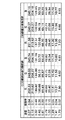
図6は、図4のステップS403において、補正用チャートの5ヶ所ある階調部のうち左端、中央、右端を読み取ることで得られる各濃度の階調パッチに対する画像読み取り輝度値の具体例を示す図である。 FIG. 6 shows a specific example of the image reading luminance value for the gradation patch of each density obtained by reading the left end, the center, and the right end among the five gradation portions of the correction chart in step S403 of FIG. FIG.
図6において、濃度とは各パッチの測定濃度を示しており、反射率は次式(1)で定義される値を示している。 In FIG. 6, the density indicates the measured density of each patch, and the reflectance indicates a value defined by the following equation (1).
![]()
![]()
式(1)において、Rは反射率、Dは濃度を表している。また、読み取り輝度値は、各パッチを複数回読み取ることで得られる輝度値の平均値を示している。 In formula (1), R represents reflectance and D represents density. The read luminance value indicates an average value of luminance values obtained by reading each patch a plurality of times.
濃度と輝度の関係を知りたいときには一般的には濃度輝度曲線で示すが、ここでは濃度の変わりに反射率と輝度の関係を図示すると図7のようになる。 When it is desired to know the relationship between density and brightness, it is generally shown by a density brightness curve. Here, the relationship between reflectance and brightness is shown in FIG. 7 instead of density.
図7は、横軸に反射率、縦軸に輝度をプロットしたものだが、このように反射率と輝度は線形関係にあるため、この線形関係を濃度リニアリティ特性と呼ぶことにする。ここでは、REDの場合のみを示しているが、GREEN、BLUEも同様な傾向を示すため、REDを代表として取り上げている。 In FIG. 7, the horizontal axis represents the reflectance and the vertical axis represents the luminance. Since the reflectance and the luminance are in a linear relationship, the linear relationship is referred to as a density linearity characteristic. Here, only the case of RED is shown, but since GREEN and BLUE show the same tendency, RED is taken as a representative.
図7に示すように、主走査方向においても濃度リニアリティ特性に差が生じてしまい、この特性差は面内の読み取り輝度ムラに起因する。この特性差により、面内においても色差(濃度差)が発生することになり、原稿に対する色(濃度)の再現性は低下してしまうことになる。 As shown in FIG. 7, there is a difference in density linearity characteristics even in the main scanning direction. This characteristic difference is caused by in-plane reading luminance unevenness. Due to this characteristic difference, a color difference (density difference) also occurs in the surface, and the reproducibility of the color (density) with respect to the original document is lowered.
そこで、この主走査方向の読み取り特性差を低減する方法を以下に説明する。 A method for reducing the difference in reading characteristics in the main scanning direction will be described below.
図4のステップS403でバックアップした測定データの全てを利用して、各パッチの読み取り輝度をCCD側の面内及びCCD側とCIS側で合わせ込んでもよいが、その際には、ルックアップテーブル(LUT)などを参照する必要がある。その場合、回路規模が大きくなり、参照用バックアップデータも莫大なものとなり、限られたメモリ資源では実現が困難な場合がある。 All the measurement data backed up in step S403 in FIG. 4 may be used to adjust the reading brightness of each patch in the CCD side and on the CCD side and CIS side. LUT) etc. need to be referred to. In this case, the circuit scale becomes large, the backup data for reference becomes enormous, and it may be difficult to realize with limited memory resources.
そこで、本実施の形態では、中間調の階調パッチのうち、低濃度側の1パッチ、高濃度側の1パッチの計2パッチのみを用いて表裏読み取り輝度の合わせ込みを行うようにした。ここでは、図6の具体例から、0.15と1.79の濃度のパッチを選択する。 Therefore, in the present embodiment, the front and back reading brightness is adjusted using only a total of two patches, one patch on the low density side and one patch on the high density side, out of the halftone patches. Here, patches having densities of 0.15 and 1.79 are selected from the specific example of FIG.
ステップS403でバックアップした濃度0.15と1.79の中間調パッチの読み取り輝度データをCCDラインセンサ126の主走査方向のそれぞれについて読み出す。
黒オフセット補正量、ゲイン補正係数の計算をRGB各色、各領域について行う。ここで、
The read luminance data of the halftone patches having the densities of 0.15 and 1.79 backed up in step S403 is read for each of the
The black offset correction amount and the gain correction coefficient are calculated for each RGB color and each region. here,

上記表1のように、各値を設定すると左端に対する中央のゲイン補正係数a及び黒オフセット補正係数bは次式により求めることができる。ゲイン補正係数a及び黒オフセット補正係数bによりシェーディング補正のゲインとオフセットを補正することで、主走査方向の中央の読取特性を、主走査方向の左端の読取特性に合わせ込み、中央と左端の読取特性差を低減する。 As shown in Table 1 , when each value is set, the central gain correction coefficient a and the black offset correction coefficient b with respect to the left end can be obtained by the following equations. By correcting the shading correction gain and offset using the gain correction coefficient a and the black offset correction coefficient b, the reading characteristics at the center in the main scanning direction are matched with the reading characteristics at the left end in the main scanning direction, and the readings at the center and the left end are performed. Reduce characteristic differences.
このようにして主走査方向の読み取り輝度差を補正した時、読み取り輝度差が最大となる個所での補正前後で比較したものを図8に示す。 FIG. 8 shows a comparison before and after correction at a position where the reading luminance difference becomes maximum when the reading luminance difference in the main scanning direction is corrected in this way.
図8からわかるように、シェーディング補正データの補正を行うことで、読み取り値の差が減少し、補正前では最大2レベル程度の差があったのに対し、補正後は1レベル以下まで改善できていることがわかる。即ち、高濃度部から低濃度部までの広い濃度範囲で表裏の読み取り特性の合わせ込みができる。 As can be seen from FIG. 8, by correcting the shading correction data, the difference in the reading value is reduced, and there was a difference of about 2 levels at the maximum before correction, but it can be improved to 1 level or less after correction. You can see that That is, the reading characteristics of the front and back sides can be adjusted in a wide density range from the high density part to the low density part.
以上に示したように、グレーの階調パッチの2パッチのみで容易に主走査方向の読み取り特性差の軽減ができる。その結果として、主走査方向の色差あるいは濃度差の軽減を図ることができる。 As described above, the reading characteristic difference in the main scanning direction can be easily reduced by using only two gray gradation patches. As a result, it is possible to reduce the color difference or density difference in the main scanning direction.
(第2実施の形態)
第1の実施の形態は、主走査方向の読み取り輝度差を低減する方法について述べた。そこで、本実施の形態では、表裏の読み取り輝度差を低減する方法について述べる。
(Second Embodiment)
In the first embodiment, the method for reducing the reading luminance difference in the main scanning direction has been described. Therefore, in the present embodiment, a method for reducing the reading luminance difference between the front and back sides will be described.
図9は、図3の画像読み取り装置によって実行される補正処理の手順を示すフローチャートである(その2)。 FIG. 9 is a flowchart showing the procedure of correction processing executed by the image reading apparatus shown in FIG. 3 (part 2).
図9において、まず、CCDラインセンサ126、CIS128の各々により上記したシェーディング白板を読み取り、シェーディング補正データを取得する(ステップS901)。
In FIG. 9, first, the above-described shading white plate is read by each of the
次に、CCDラインセンサ126、CIS128の各々により、図5に示すようなグレースケール等の中間調の階調パッチを複数個有する補正用チャート(基準原稿)を読み込む(ステップS902)。この基準原稿は読み取り輝度の面内ムラを補正する役割もするため、シェーディング白板と同様に各パッチの濃度は面内で一様である必要がある。
Next, each of the
補正用チャートを読み取ることで得られる各濃度の階調パッチに対する画像読み取り輝度値を、CCD側、CIS側ともにバックアップしておく(ステップS903)。バックアップされた各濃度の階調パッチに対する輝度値に基づいて、CCD側、CIS側それぞれに対するシェーディング補正データを補正するための補正係数を算出する(ステップS904及びS905)。そして処理を終了する。 The image reading luminance value for each density gradation patch obtained by reading the correction chart is backed up on both the CCD side and the CIS side (step S903). Based on the luminance values for the back-up gradation patches of each density, correction coefficients for correcting the shading correction data for the CCD side and the CIS side are calculated (steps S904 and S905). Then, the process ends.
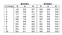
図10は、図9のステップS903において、補正用チャートを読み取ることで得られる各濃度の階調パッチに対する画像読み取り輝度値の具体例を示す図である。 FIG. 10 is a diagram showing a specific example of image reading luminance values for gradation patches of respective densities obtained by reading the correction chart in step S903 of FIG.
ここでは、図5に示すチャートの中央部の階調パッチの読み取り輝度を代表として挙げた。しかし、実際は表裏の各対応領域で以下に説明する方法を実行する必要があるが、各領域に同じ処理を行えばよく、全て記載すると煩雑になるため割愛する。 Here, the reading luminance of the gradation patch at the center of the chart shown in FIG. However, in practice, it is necessary to execute the method described below in each of the corresponding areas on the front and back sides, but the same process may be performed on each area.
さらに、REDの場合のみを示しているが、GREEN、BLUEも同様な傾向を示すため、REDを代表として取り上げている。また、CCD側読み取り輝度値及びCIS側読み取り輝度値には、各パッチを複数回読み取ることで得られる輝度値の平均値を示している。 Furthermore, only the case of RED is shown, but GREEN and BLUE also show the same tendency, so RED is taken as a representative. The CCD side reading luminance value and the CIS side reading luminance value indicate average values of luminance values obtained by reading each patch a plurality of times.
図11に示すように、面内においても表裏においても濃度リニアリティ特性に差が生じてしまい、この特性差は表裏読み取り輝度差に起因する。そこで、表裏読み取り特性差を低減する方法を以下に述べる。 As shown in FIG. 11, there is a difference in density linearity characteristics both in the surface and in the front and back, and this characteristic difference is caused by a difference in reading luminance between the front and back surfaces. A method for reducing the difference between the front and back reading characteristics will be described below.
図9のステップS903でバックアップした測定データの全てを利用して、各パッチの読み取り輝度をCCD側の面内及びCCD側とCIS側で合わせ込んでもよいが、その際には、ルックアップテーブル(LUT)などを参照する必要がある。その結果、回路規模が大きくなり、参照用バックアップデータも莫大なものとなり、限られたメモリ資源では実現が困難な場合がある。 All the measurement data backed up in step S903 in FIG. 9 may be used to adjust the reading brightness of each patch in the CCD side and on the CCD side and the CIS side. LUT) etc. need to be referred to. As a result, the circuit scale becomes large and the backup data for reference becomes enormous, which may be difficult to realize with limited memory resources.
そこで、本実施の形態では、中間調の階調パッチのうち、低濃度側の1パッチ、高濃度側の1パッチの計2パッチのみを用いて表裏読み取り輝度の合わせ込みを行うようにした。ここでは、図8の具体例から、0.15と1.79の濃度のパッチを選択する。 Therefore, in the present embodiment, the front and back reading brightness is adjusted using only a total of two patches, one patch on the low density side and one patch on the high density side, out of the halftone patches. Here, patches having densities of 0.15 and 1.79 are selected from the specific example of FIG.
図12は、図9のステップのS904及びS905で実行される補正係数算出処理の手順を示すフローチャートである。 FIG. 12 is a flowchart showing the procedure of the correction coefficient calculation process executed in steps S904 and S905 of FIG.
図12において、まず図9のステップS903でバックアップした濃度0.15と1.79の中間調パッチの読み取り輝度データをCCDラインセンサ126、CIS128のそれぞれについて読み出す(ステップS1201)。
In FIG. 12, first, the read luminance data of the halftone patches of density 0.15 and 1.79 backed up in step S903 of FIG. 9 are read for each of the
黒オフセット補正係数、ゲイン補正係数の計算をRGB各色、各領域について行う(ステップS1202、S1203)。上記(2)、(3)式を使用する。具体値に対してシェーディング補正データの補正を行う(ステップS1204)。その結果は、図13のようになる。そして処理を終了する。 The black offset correction coefficient and the gain correction coefficient are calculated for each of the RGB colors and regions (steps S1202 and S1203). The above formulas (2) and (3) are used. The shading correction data is corrected for the specific value (step S1204). The result is as shown in FIG. Then, the process ends.
CCD側の読み値とCIS側の読み値の差を補正前後で比較したものを図14に示す。図14からわかるように、シェーディング補正データの補正を行うことで、読み取り値の差が減少し、補正前では最大8レベル程度の差があったのに対し、補正後は最大でも3レベル程度まで改善できている。即ち、高濃度部から低濃度部までの広い濃度範囲で表裏の読み取り特性の合わせ込みができる。 FIG. 14 shows a comparison between the reading value on the CCD side and the reading value on the CIS side before and after correction. As can be seen from FIG. 14, by correcting the shading correction data, the difference between the read values is reduced, and there is a difference of about 8 levels at the maximum before correction, but up to about 3 levels after the correction. It has improved. That is, the reading characteristics of the front and back sides can be adjusted in a wide density range from the high density part to the low density part.
以上に示したように、グレーの階調パッチの2パッチのみで容易に表裏読み取り特性差の軽減ができる。その結果として、表裏色差(表裏濃度差)の軽減も図ることができる。 As described above, the difference between the front and back reading characteristics can be easily reduced with only two gray gradation patches. As a result, the front and back color difference (front and back density difference) can be reduced.
なお、以上の本実施の形態では、原稿表面画像読み取りにCCDラインセンサ126を用いた縮小光学系、原稿裏面画像読み取りにCIS128を用いた等倍光学系を使用した場合を例に説明した。
In the above-described embodiment, the case where the reduction optical system using the
本実施の形態の構成とは逆に、原稿表面画像読み取りにCIS128を用いた等倍光学系を採用し、原稿裏面画像読み取りにCCDラインセンサ126を用いた縮小光学系を採用してもよい。
Contrary to the configuration of the present embodiment, an equal magnification optical system using CIS128 may be adopted for reading the document surface image, and a reduction optical system using the
(第3の実施の形態)
本実施の形態では、低濃度部、高濃度部からそれぞれ2パッチの計4パッチを選択した場合の面内及び表裏読み取り特性の合わせ込みについて述べる。具体的には、図10の具体例から、低濃度部から0.15と0.45のパッチ、高濃度部から1.00と1.79の濃度のパッチを選択した場合の面内及び表裏読み取り特性の合わせ込みについて述べる。
(Third embodiment)
In the present embodiment, adjustment of in-plane and front / back reading characteristics when a total of four patches of two patches each from the low density part and the high density part are selected will be described. Specifically, from the specific example of FIG. 10, in-plane and front and back surfaces when patches of 0.15 and 0.45 from the low density portion and patches of 1.00 and 1.79 from the high density portion are selected. The adjustment of reading characteristics will be described.
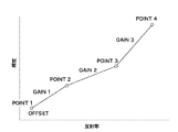
図15は、濃度リニアリティ特性を4パッチ濃度の4点で補正を行う際の概念図である。 FIG. 15 is a conceptual diagram when the density linearity characteristic is corrected at four points of four patch densities.
図15に示すように、4点で濃度リニアリティ特性を補正する場合には、黒レベルオフセット値を1点、ゲイン値を3通り設定する必要があることがわかる。つまり、任意のn点(nは2以上の整数)では、1点の黒レベルオフセット値、n−1通りのゲイン値の設定が必要となる。 As shown in FIG. 15, when correcting the density linearity characteristic at four points, it is necessary to set one black level offset value and three gain values. That is, at an arbitrary n point (n is an integer of 2 or more), it is necessary to set one black level offset value and n-1 gain values.
裏(CIS)の読み取り特性を表(CCD)の読み取り特性に合わせ込むためのPOINT1からPOINT2間、POINT2からPOINT3間、POINT3からPOINT4間でのゲイン補正係数a1〜a3、黒オフセット補正係数bは、下表のように値を定めると次式(4)〜(6)により求められる。 Gain adjustment coefficients a1 to a3 and black offset correction coefficient b between POINT1 and POINT2, between POINT2 and POINT3, and between POINT3 and POINT4 for adjusting the reading characteristics of the back (CIS) to the reading characteristics of the front (CCD) are as follows: When values are determined as shown in the following table, they are obtained by the following equations (4) to (6).
なお、上記の計算はPOINT1からPOINT2の範囲、POINT2からPOINT3の範囲と、順を追って行うものとする。 Note that the above calculation is performed in the order of the range from POINT1 to POINT2, and the range from POINT2 to POINT3.
図10の具体例に対して上記補正方法を用いて補正した結果を図16に示す。また、CCD側の読み値とCIS側の読み値の差を本願発明の補正前後で比較したものを図17に示す。 FIG. 16 shows the result of correcting the specific example of FIG. 10 using the above correction method. FIG. 17 shows a comparison between the CCD side reading value and the CIS side reading value before and after correction of the present invention.
図17より、4点補正を行うことで、読み取り輝度値の差が減少し、補正前では最大8レベル程度の差があったのに対し、補正後は最大でも3レベル程度まで改善できていることがわかる。 From FIG. 17, by performing the four-point correction, the difference in the read luminance value is reduced, and there was a difference of about 8 levels at the maximum before the correction, but it can be improved to about 3 levels at the maximum after the correction. I understand that.
なお、上記実施の形態は、カラーでの読み取りの場合について述べたが、白黒の場合でも全く同じ方法で表裏の読み取り特性差を減少させることができ、コピー原稿出力時に表裏の濃度差を低減することができる。 In the above embodiment, the case of reading in color has been described. However, even in the case of black and white, the difference in reading characteristics between the front and back sides can be reduced by the same method, and the density difference between the front and back sides can be reduced when outputting a copy document. be able to.
(第4の実施の形態)
上記第1乃至第3の実施の形態では、主走査方向の読み取り特性及び表裏の読み取り特性の合わせ込み方法について詳細に述べた。
(Fourth embodiment)
In the first to third embodiments, the method for adjusting the reading characteristics in the main scanning direction and the reading characteristics of the front and back sides has been described in detail.
しかし、同じ濃度のパッチであっても、原稿面の状態、つまり、原稿面に光沢があり「つるつる」している場合と、原稿面に光沢がなく「ざらざら」している場合とによって、読み取り特性が大きく異なってくる。 However, even patches of the same density are read depending on the state of the original surface, that is, when the original surface is glossy and "smooth" and when the original surface is not glossy and is "gritty" The characteristics are greatly different.
図18は、原稿面に光沢がある原稿と光沢がない原稿での濃度リニアリティ特性を示す図である。 FIG. 18 is a diagram illustrating density linearity characteristics of a document having a glossy document surface and a document having no gloss.
図18(a)は、全濃度範囲における濃度リニアリティ特性を示し、(b)は、その高濃度範囲を拡大したものである。このように原稿面の特性により、濃度リニアリティが大きく異なることがわかる。 FIG. 18A shows density linearity characteristics in the entire density range, and FIG. 18B is an enlarged view of the high density range. Thus, it can be seen that the density linearity varies greatly depending on the characteristics of the original surface.
従って、上記第1実施の形態で説明したように、表裏の読み取り特性の合わせ込みを行う際に、さらに読み取る原稿面の特性に合わせて、黒オフセット値及びゲイン値の補正を行うことで、より精度の高い表裏読み取り特性合わせ込みが可能となる。 Therefore, as described in the first embodiment, when the reading characteristics of the front and back sides are adjusted, the black offset value and the gain value are further corrected in accordance with the characteristics of the original surface to be read. It is possible to match the reading characteristics of the front and back with high accuracy.
図19は、図3の画像読み取り装置によって実行されるモードごとの補正処理の手順を示すフローチャートである。 FIG. 19 is a flowchart showing the procedure of the correction process for each mode executed by the image reading apparatus of FIG.
具体的には、ユーザがどのような特性を持つ原稿を読み取らせるかをユーザインタフェースの画面で選択し、選択された結果に基づいて読み取りモードを設定し、モードに応じた補正処理を行うフローチャートである。 Specifically, a flowchart for selecting what kind of characteristics the user should read on the user interface screen, setting a reading mode based on the selected result, and performing correction processing according to the mode. is there.
ここでは、原稿の光沢の有無だけでなく、オフセット印刷された原稿、電子写真出力された原稿の4種類の原稿面特性から選択できる例を示している。さらに、黒オフセット値及びゲイン値を任意に変更できる機構を有するような構成としてもよい。 In this example, not only the glossiness of the document but also four types of document surface characteristics of an offset printed document and an electrophotographic document can be selected. Furthermore, it is good also as a structure which has a mechanism which can change a black offset value and a gain value arbitrarily.
図19において、表面性を判断し(ステップS1901)、光沢がない場合は、光沢なし原稿モードを選択する(ステップS1902)。光沢がある場合は、原稿種を判断する(ステップS1903)。そして、原稿種に応じて、光沢あり原稿モード、オフセット印刷原稿モード、電子写真原稿モードを設定する(ステップS1904乃至ステップS1906)。最後に設定された各モードに応じて黒オフセット値補正処理ねゲイン値補正処理を実行し(ステップS1907)、処理を終了する。 In FIG. 19, the surface property is judged (step S1901), and when the gloss is not glossy, the glossy original mode is selected (step S1902). If it is glossy, the document type is determined (step S1903). Then, the glossy document mode, the offset print document mode, and the electrophotographic document mode are set according to the document type (steps S1904 to S1906). The black offset value correction process and the gain value correction process are executed in accordance with the last set mode (step S1907), and the process ends.
(第5の実施の形態)
上記第1乃至第3の実施の形態では、表面画像読み取りと裏面画像読み取りの撮像素子を備える光学系が、縮小光学系と等倍光学系で異なる場合について述べた。
(Fifth embodiment)
In the first to third embodiments, the case has been described in which the optical system including the imaging device for reading the front surface image and the back surface image is different between the reduction optical system and the equal magnification optical system.
本実施の形態では、表面画像読み取りと裏面画像読み取りの読み取り光学系の種類が同じ場合、例として、2つのCCDラインセンサを備えた縮小光学系を表裏読み取り装置として用いた場合について述べる。 In this embodiment, when the types of reading optical systems for reading the front surface image and the back surface image are the same, a case where a reduction optical system including two CCD line sensors is used as the front and back reading device will be described as an example.
画像読み取り装置の各構成要素、つまり、ランプやガラス、レンズやミラー等には製造ばらつきがあるため、同じ種類の読み取り光学系を、原稿表裏の読み取りに用いた場合でも、表裏画像読み取り装置間での読み取り特性は若干異なる。 Each component of the image reading device, that is, lamp, glass, lens, mirror, etc. has manufacturing variations, so even if the same type of reading optical system is used for reading the front and back of the document, The reading characteristics are slightly different.
図20は、CCDラインセンサを備えた縮小光学系を表裏読み取りの双方に用いた場合の表裏濃度リニアリティ特性を比較する図である。 FIG. 20 is a diagram comparing front and back density linearity characteristics when a reduction optical system including a CCD line sensor is used for both front and back reading.
このように、同じ光学系を表裏の読み取りに用いた場合でも、表面の読み取り特性と裏面の読み取り特性は異なる。また、同じ面の原稿でも原稿台ガラス118でスキャンする場合と、自動原稿給送装置100を使用して流し読みでスキャンする場合でも、表裏の読み取り特性は異なってくる。
Thus, even when the same optical system is used for reading the front and back surfaces, the reading characteristics on the front surface and the reading characteristics on the back surface are different. In addition, the reading characteristics of the front and back sides differ even when a document on the same side is scanned by the
従って、上記各実施の形態の表裏読み取り特性の補正に際しては、読み取りモードが異なる場合、表裏画像読み取り装置が同じ場合、表裏画像読み取り装置が異なる場合等のいかなる態様であっても、表裏読み取り特性差を高精度に合わせ込むことができる。またそのための構成も簡素なもので済む。 Accordingly, when correcting the front / back reading characteristics of each of the above embodiments, the front / back reading characteristics difference is different in any mode, such as when the reading mode is different, when the front / back image reading apparatus is the same, or when the front / back image reading apparatus is different. Can be adjusted with high accuracy. Also, a simple configuration is sufficient for this purpose.
100 自動原稿給送装置
116、117 流し読みガラス
126 CCDラインイメージセンサ(読み取り手段)
128 CIS(読み取り手段)
302 CCD駆動回路
303 A/D変換部
304 画像処理ASIC(画像補正手段)
305 SDRAM
100
128 CIS (reading means)
302 CCD drive circuit 303 A /
305 SDRAM
Claims (4)
白基準部材を前記読取手段により読み取って得られたシェーディング補正のためのゲイン及び光源を消灯した状態における前記読取手段の出力値に基づくオフセットによって、前記原稿画像を前記読取手段により読み取って得られた原稿画像データに対してシェーディング補正を行うシェーディング補正手段と、
少なくとも2つの異なる濃度の濃度パターンを有する濃度基準原稿を前記読取手段の主走査方向の複数位置にてそれぞれ読み取って得られた読取データに基づいたゲイン補正値及びオフセット補正値によって、前記読取手段の主走査方向の複数位置の読取特性差を低減するように前記シェーディング補正のためのゲイン及びオフセットを補正するデータ補正手段と、を有することを特徴とする画像読取装置。 Reading means for reading a document image;
Obtained by reading the original image by the reading means with the gain based on the shading correction obtained by reading the white reference member by the reading means and the offset based on the output value of the reading means in a state where the light source is turned off . and shading correction means for performing shading correction on the original image data,
According to the gain correction value and the offset correction value based on the read data obtained by reading density reference documents having density patterns of at least two different densities at a plurality of positions in the main scanning direction of the reading means, An image reading apparatus comprising: data correction means for correcting the gain and offset for the shading correction so as to reduce a difference in reading characteristics at a plurality of positions in the main scanning direction.
前記原稿の裏面画像を読み取る第2の読取手段と、
白基準部材を前記第1及び第2の読取手段のそれぞれにより読み取って得られたシェーディング補正のための第1及び第2のゲイン並びに光源を消灯した状態における該第1及び第2の読取手段それぞれの出力値に基づく第1及び第2のオフセットによって、前記原稿の前記表面画像及び前記裏面画像をそれぞれ前記第1及び第2の読取手段により読み取って得られた第1及び第2の原稿画像データそれぞれに対してシェーディング補正を行うシェーディング補正手段と、
少なくとも2つの異なる濃度の濃度パターンを有する濃度基準原稿を前記第1及び第2の読取手段によりそれぞれ読み取って得られた読取データに基づいたゲイン補正値及びオフセット補正値によって、前記第1及び第2の読取手段の読取特性差を低減するように前記第1のゲインと前記第1のオフセット及び前記第2のゲインと前記第2のオフセットの両方または一方のゲイン及びオフセットを補正するデータ補正手段と、を有することを特徴とする画像読取装置。 First reading means for reading a surface image of a document;
Second reading means for reading a back side image of the original;
First and second reading means in a state in which turns off the first and second gain and the light source for the sheet Edingu correction obtained by reading by each of the white reference member wherein the first and second reading means First and second original images obtained by reading the front and back images of the original by the first and second reading means, respectively, with the first and second offsets based on the respective output values. and line cormorant shading correction means a shading correction on the data, respectively,
According to the gain correction value and the offset correction value based on the read data obtained by reading the density reference documents having density patterns of at least two different densities by the first and second reading units, respectively, the first and second Data correction means for correcting the first gain and the first offset and / or the second gain and / or the second offset so as to reduce a difference in reading characteristics of the reading means. And an image reading apparatus.
前記原稿画像を前記読取手段により読み取る読取ステップと、
白基準部材を前記読取手段により読み取って得られたシェーディング補正のためのゲイン及び光源を消灯した状態における前記読取手段の出力値に基づくオフセットによって、前記原稿画像を前記読取手段により読み取って得られた原稿画像データに対してシェーディング補正を行うシェーディング補正ステップと、
少なくとも2つの異なる濃度の濃度パターンを有する濃度基準原稿を前記読取手段の主走査方向の複数位置にてそれぞれ読み取って得られた読取データに基づいたゲイン補正値及びオフセット補正値によって、前記読取手段の主走査方向の複数位置の読取特性差を低減するように前記シェーディング補正のためのゲイン及びオフセットを補正するデータ補正ステップと、を有することを特徴とする画像読取装置の制御方法。 A method for controlling an image reading apparatus having a reading unit for reading a document image,
A reading step of reading the document image by the reading unit;
Obtained by reading the original image by the reading means with the gain based on the shading correction obtained by reading the white reference member by the reading means and the offset based on the output value of the reading means in a state where the light source is turned off . a shading correction step of performing shading correction on the original image data,
According to the gain correction value and the offset correction value based on the read data obtained by reading density reference documents having density patterns of at least two different densities at a plurality of positions in the main scanning direction of the reading means, And a data correction step of correcting a gain and an offset for the shading correction so as to reduce a reading characteristic difference between a plurality of positions in the main scanning direction.
前記原稿の表面画像を前記第1の読取手段により読み取る第1の読取ステップと、
前記原稿の裏面画像を前記第2の読取手段により読み取る第2の読取ステップと、
白基準部材を前記第1及び第2の読取手段のそれぞれにより読み取って得られたシェーディング補正のための第1及び第2のゲイン並びに光源を消灯した状態における該第1及び第2の読取手段それぞれの出力値に基づく第1及び第2のオフセットによって、前記原稿の前記表面画像及び前記裏面画像をそれぞれ前記第1及び第2の読取手段により読み取って得られた第1及び第2の原稿画像データそれぞれに対してシェーディング補正を行うシェーディング補正ステップと、
少なくとも2つの異なる濃度の濃度パターンを有する濃度基準原稿を前記第1及び第2の読取手段によりそれぞれ読み取って得られた読取データに基づいたゲイン補正値及びオフセット補正値によって、前記第1及び第2の読取手段の読取特性差を低減するように前記第1のゲインと前記第1のオフセット及び前記第2のゲインと前記第2のオフセットの両方または一方のゲイン及びオフセットを補正するデータ補正ステップと、を有することを特徴とする画像読取装置の制御方法。 A control method for an image reading apparatus, comprising: a first reading unit that reads a front image of a document; and a second reading unit that reads a back image of the document.
A first reading step of reading a surface image of the original by the first reading unit;
A second reading step of reading the back side image of the document by the second reading unit;
First and second reading means in a state in which turns off the first and second gain and the light source for the sheet Edingu correction obtained by reading by each of the white reference member wherein the first and second reading means First and second original images obtained by reading the front and back images of the original by the first and second reading means, respectively, with the first and second offsets based on the respective output values. and line cormorant shading correction step shading correction on the data, respectively,
According to the gain correction value and the offset correction value based on the read data obtained by reading the density reference documents having density patterns of at least two different densities by the first and second reading units, respectively, the first and second A data correction step of correcting the first gain and the first offset and / or the second gain and / or the second offset so as to reduce a difference in reading characteristics of the reading means. And a method of controlling the image reading apparatus.
Priority Applications (2)
| Application Number | Priority Date | Filing Date | Title |
|---|---|---|---|
| JP2006253208A JP4785690B2 (en) | 2006-09-19 | 2006-09-19 | Image reading apparatus and method for controlling image reading apparatus |
| US11/857,534 US7729023B2 (en) | 2006-09-19 | 2007-09-19 | Image reading apparatus and image reading method |
Applications Claiming Priority (1)
| Application Number | Priority Date | Filing Date | Title |
|---|---|---|---|
| JP2006253208A JP4785690B2 (en) | 2006-09-19 | 2006-09-19 | Image reading apparatus and method for controlling image reading apparatus |
Publications (3)
| Publication Number | Publication Date |
|---|---|
| JP2008078798A JP2008078798A (en) | 2008-04-03 |
| JP2008078798A5 JP2008078798A5 (en) | 2009-11-19 |
| JP4785690B2 true JP4785690B2 (en) | 2011-10-05 |
Family
ID=39188276
Family Applications (1)
| Application Number | Title | Priority Date | Filing Date |
|---|---|---|---|
| JP2006253208A Active JP4785690B2 (en) | 2006-09-19 | 2006-09-19 | Image reading apparatus and method for controlling image reading apparatus |
Country Status (2)
| Country | Link |
|---|---|
| US (1) | US7729023B2 (en) |
| JP (1) | JP4785690B2 (en) |
Families Citing this family (25)
| Publication number | Priority date | Publication date | Assignee | Title |
|---|---|---|---|---|
| JP4250000B2 (en) * | 2003-03-03 | 2009-04-08 | 東芝テック株式会社 | Image reading apparatus and image reading method |
| CN101150643B (en) * | 2006-09-20 | 2010-11-03 | 佳能株式会社 | Image reading apparatus |
| JP4818038B2 (en) * | 2006-09-25 | 2011-11-16 | キヤノン株式会社 | Image reading device |
| JP4356766B2 (en) * | 2007-04-24 | 2009-11-04 | 村田機械株式会社 | Image copying apparatus and image data correction method |
| JP4310351B2 (en) * | 2007-05-31 | 2009-08-05 | キヤノン株式会社 | Image reading apparatus and reading characteristic correction method for image reading apparatus |
| JP5287001B2 (en) * | 2008-07-14 | 2013-09-11 | 株式会社リコー | Image forming apparatus |
| JP5245883B2 (en) * | 2009-02-06 | 2013-07-24 | 株式会社リコー | Image processing apparatus, image forming apparatus, image processing method, and program |
| JP4794662B2 (en) * | 2009-07-31 | 2011-10-19 | シャープ株式会社 | Image reading apparatus and image determination method |
| CN107071480A (en) * | 2009-12-18 | 2017-08-18 | 夏普株式会社 | Decoding apparatus |
| JP4865935B2 (en) | 2009-12-28 | 2012-02-01 | キヤノン・コンポーネンツ株式会社 | Contact image sensor unit and image reading apparatus using the same |
| JP2012080505A (en) * | 2010-10-06 | 2012-04-19 | Konica Minolta Business Technologies Inc | Image processing device, printing device and image processing method |
| JP5139507B2 (en) | 2010-12-10 | 2013-02-06 | キヤノン・コンポーネンツ株式会社 | Image sensor unit and image reading apparatus |
| JP5220089B2 (en) * | 2010-12-17 | 2013-06-26 | キヤノン株式会社 | Document reader |
| JP5204207B2 (en) | 2010-12-17 | 2013-06-05 | キヤノン・コンポーネンツ株式会社 | Image sensor unit and image reading apparatus using the same |
| JP5244952B2 (en) * | 2010-12-21 | 2013-07-24 | キヤノン・コンポーネンツ株式会社 | Image sensor unit and image reading apparatus |
| JP5384471B2 (en) | 2010-12-28 | 2014-01-08 | キヤノン・コンポーネンツ株式会社 | Image sensor unit and image reading apparatus |
| JP5400188B2 (en) | 2011-05-11 | 2014-01-29 | キヤノン・コンポーネンツ株式会社 | Image sensor unit and image reading apparatus and image forming apparatus using the same |
| JP5384707B2 (en) | 2011-08-09 | 2014-01-08 | キヤノン・コンポーネンツ株式会社 | Image sensor unit and image reading apparatus using the same |
| JP5518953B2 (en) | 2011-08-09 | 2014-06-11 | キヤノン・コンポーネンツ株式会社 | Image sensor unit and image reading apparatus |
| JP5536150B2 (en) | 2011-08-09 | 2014-07-02 | キヤノン・コンポーネンツ株式会社 | Image sensor unit and image reading apparatus |
| JP6060532B2 (en) * | 2012-06-18 | 2017-01-18 | 株式会社リコー | Image reading apparatus and image forming apparatus |
| JP2014041203A (en) * | 2012-08-21 | 2014-03-06 | Canon Inc | Image forming device |
| TWI571098B (en) * | 2016-01-06 | 2017-02-11 | 虹光精密工業股份有限公司 | Scanning device and image forming system using such scanning device |
| JP7010131B2 (en) | 2018-04-24 | 2022-01-26 | 株式会社リコー | Color inspection equipment, image forming equipment, color inspection methods and programs |
| FR3110703A1 (en) | 2020-05-20 | 2021-11-26 | Vetophage | DEVICE FOR DETECTION OF BACTERIA OF INTEREST |
Family Cites Families (6)
| Publication number | Priority date | Publication date | Assignee | Title |
|---|---|---|---|---|
| JP3660180B2 (en) | 1999-11-26 | 2005-06-15 | シャープ株式会社 | Image processing device |
| JP3501717B2 (en) | 2000-03-30 | 2004-03-02 | キヤノン株式会社 | Image reading device, opaque object detection method, and storage medium |
| JP2004086013A (en) * | 2002-08-28 | 2004-03-18 | Canon Inc | Method and device for correcting shading of sensor and color image forming apparatus |
| JP2004187144A (en) | 2002-12-05 | 2004-07-02 | Canon Inc | Image reading apparatus |
| JP2004328481A (en) * | 2003-04-25 | 2004-11-18 | Canon Inc | Image reader and image reading method |
| JP4442272B2 (en) * | 2004-03-22 | 2010-03-31 | 富士ゼロックス株式会社 | Image reading device and foreign material detection method for reference member |
-
2006
- 2006-09-19 JP JP2006253208A patent/JP4785690B2/en active Active
-
2007
- 2007-09-19 US US11/857,534 patent/US7729023B2/en active Active
Also Published As
| Publication number | Publication date |
|---|---|
| JP2008078798A (en) | 2008-04-03 |
| US7729023B2 (en) | 2010-06-01 |
| US20080068682A1 (en) | 2008-03-20 |
Similar Documents
| Publication | Publication Date | Title |
|---|---|---|
| JP4785690B2 (en) | Image reading apparatus and method for controlling image reading apparatus | |
| JP4570670B2 (en) | Image processing apparatus, image reading apparatus, image forming apparatus, image processing method, image processing program, and recording medium | |
| US6806980B2 (en) | Adaptive illumination correction of scanned images | |
| JP5239836B2 (en) | Image processing apparatus, image forming apparatus, image processing method, and program | |
| JP5430364B2 (en) | Image forming apparatus | |
| JP2008301213A (en) | Image reading device and reading characteristic correction method of image reading device | |
| JP4859233B2 (en) | Document reading apparatus and image processing method | |
| JP4989121B2 (en) | Image reading device | |
| JP2012044445A (en) | Image reader | |
| JP2012129909A (en) | Document reading apparatus and image processing method | |
| JP2015104125A (en) | Document handler using dual height calibration target for automatic calibration | |
| JP2013012898A (en) | Image reader and image forming apparatus | |
| JP2011150026A (en) | Image processor, image processing method, and program | |
| US20050073703A1 (en) | Image processing device and method for performing gamma correction | |
| JP4024737B2 (en) | Image processing apparatus, image reading apparatus, image forming apparatus, image processing method, and program | |
| JP2010103808A (en) | Image processor, image reader, image forming apparatus, image processing method, image processing program and computer readable recording medium | |
| JP2002059626A (en) | Imaging apparatus | |
| JP2013017134A (en) | Image reader, calibration method, and calibration program | |
| US20060082839A1 (en) | System for processing image signals from an image scanner having a platen and a document handler | |
| JP2010114648A (en) | Image processor, image processing method, and program executable by computer | |
| JP5245883B2 (en) | Image processing apparatus, image forming apparatus, image processing method, and program | |
| JP5112368B2 (en) | Image forming apparatus and image forming method | |
| JP2011045066A (en) | Image processor and image processing method | |
| JP2011166735A (en) | Image processing apparatus and image processing method | |
| JP2010212819A (en) | Method for determining position of led array, and led array |
Legal Events
| Date | Code | Title | Description |
|---|---|---|---|
| A521 | Written amendment |
Free format text: JAPANESE INTERMEDIATE CODE: A523 Effective date: 20090918 |
|
| A621 | Written request for application examination |
Free format text: JAPANESE INTERMEDIATE CODE: A621 Effective date: 20090918 |
|
| A521 | Written amendment |
Free format text: JAPANESE INTERMEDIATE CODE: A523 Effective date: 20090929 |
|
| A977 | Report on retrieval |
Free format text: JAPANESE INTERMEDIATE CODE: A971007 Effective date: 20101007 |
|
| A131 | Notification of reasons for refusal |
Free format text: JAPANESE INTERMEDIATE CODE: A131 Effective date: 20101013 |
|
| A521 | Written amendment |
Free format text: JAPANESE INTERMEDIATE CODE: A523 Effective date: 20101210 |
|
| A131 | Notification of reasons for refusal |
Free format text: JAPANESE INTERMEDIATE CODE: A131 Effective date: 20110419 |
|
| A521 | Written amendment |
Free format text: JAPANESE INTERMEDIATE CODE: A523 Effective date: 20110620 |
|
| TRDD | Decision of grant or rejection written | ||
| A01 | Written decision to grant a patent or to grant a registration (utility model) |
Free format text: JAPANESE INTERMEDIATE CODE: A01 Effective date: 20110705 |
|
| A01 | Written decision to grant a patent or to grant a registration (utility model) |
Free format text: JAPANESE INTERMEDIATE CODE: A01 |
|
| A61 | First payment of annual fees (during grant procedure) |
Free format text: JAPANESE INTERMEDIATE CODE: A61 Effective date: 20110712 |
|
| R151 | Written notification of patent or utility model registration |
Ref document number: 4785690 Country of ref document: JP Free format text: JAPANESE INTERMEDIATE CODE: R151 |
|
| FPAY | Renewal fee payment (event date is renewal date of database) |
Free format text: PAYMENT UNTIL: 20140722 Year of fee payment: 3 |