JP4785149B2 - Ultrasonic diagnostic apparatus and operation method thereof - Google Patents
Ultrasonic diagnostic apparatus and operation method thereof Download PDFInfo
- Publication number
- JP4785149B2 JP4785149B2 JP2007502633A JP2007502633A JP4785149B2 JP 4785149 B2 JP4785149 B2 JP 4785149B2 JP 2007502633 A JP2007502633 A JP 2007502633A JP 2007502633 A JP2007502633 A JP 2007502633A JP 4785149 B2 JP4785149 B2 JP 4785149B2
- Authority
- JP
- Japan
- Prior art keywords
- ultrasonic
- ultrasonic image
- dimensional
- dimensional ultrasonic
- image
- Prior art date
- Legal status (The legal status is an assumption and is not a legal conclusion. Google has not performed a legal analysis and makes no representation as to the accuracy of the status listed.)
- Expired - Fee Related
Links
Images


Classifications
-
- A—HUMAN NECESSITIES
- A61—MEDICAL OR VETERINARY SCIENCE; HYGIENE
- A61B—DIAGNOSIS; SURGERY; IDENTIFICATION
- A61B8/00—Diagnosis using ultrasonic, sonic or infrasonic waves
-
- A—HUMAN NECESSITIES
- A61—MEDICAL OR VETERINARY SCIENCE; HYGIENE
- A61B—DIAGNOSIS; SURGERY; IDENTIFICATION
- A61B8/00—Diagnosis using ultrasonic, sonic or infrasonic waves
- A61B8/08—Detecting organic movements or changes, e.g. tumours, cysts, swellings
-
- A—HUMAN NECESSITIES
- A61—MEDICAL OR VETERINARY SCIENCE; HYGIENE
- A61B—DIAGNOSIS; SURGERY; IDENTIFICATION
- A61B8/00—Diagnosis using ultrasonic, sonic or infrasonic waves
- A61B8/42—Details of probe positioning or probe attachment to the patient
- A61B8/4245—Details of probe positioning or probe attachment to the patient involving determining the position of the probe, e.g. with respect to an external reference frame or to the patient
- A61B8/4254—Details of probe positioning or probe attachment to the patient involving determining the position of the probe, e.g. with respect to an external reference frame or to the patient using sensors mounted on the probe
-
- A—HUMAN NECESSITIES
- A61—MEDICAL OR VETERINARY SCIENCE; HYGIENE
- A61B—DIAGNOSIS; SURGERY; IDENTIFICATION
- A61B8/00—Diagnosis using ultrasonic, sonic or infrasonic waves
- A61B8/48—Diagnostic techniques
- A61B8/483—Diagnostic techniques involving the acquisition of a 3D volume of data
-
- G—PHYSICS
- G01—MEASURING; TESTING
- G01S—RADIO DIRECTION-FINDING; RADIO NAVIGATION; DETERMINING DISTANCE OR VELOCITY BY USE OF RADIO WAVES; LOCATING OR PRESENCE-DETECTING BY USE OF THE REFLECTION OR RERADIATION OF RADIO WAVES; ANALOGOUS ARRANGEMENTS USING OTHER WAVES
- G01S15/00—Systems using the reflection or reradiation of acoustic waves, e.g. sonar systems
- G01S15/88—Sonar systems specially adapted for specific applications
- G01S15/89—Sonar systems specially adapted for specific applications for mapping or imaging
- G01S15/8906—Short-range imaging systems; Acoustic microscope systems using pulse-echo techniques
- G01S15/8993—Three dimensional imaging systems
-
- A—HUMAN NECESSITIES
- A61—MEDICAL OR VETERINARY SCIENCE; HYGIENE
- A61B—DIAGNOSIS; SURGERY; IDENTIFICATION
- A61B8/00—Diagnosis using ultrasonic, sonic or infrasonic waves
- A61B8/08—Detecting organic movements or changes, e.g. tumours, cysts, swellings
- A61B8/0866—Detecting organic movements or changes, e.g. tumours, cysts, swellings involving foetal diagnosis; pre-natal or peri-natal diagnosis of the baby
Landscapes
- Health & Medical Sciences (AREA)
- Life Sciences & Earth Sciences (AREA)
- Engineering & Computer Science (AREA)
- Physics & Mathematics (AREA)
- Medical Informatics (AREA)
- Animal Behavior & Ethology (AREA)
- Radiology & Medical Imaging (AREA)
- Nuclear Medicine, Radiotherapy & Molecular Imaging (AREA)
- Biomedical Technology (AREA)
- Heart & Thoracic Surgery (AREA)
- Biophysics (AREA)
- Molecular Biology (AREA)
- Surgery (AREA)
- Pathology (AREA)
- General Health & Medical Sciences (AREA)
- Public Health (AREA)
- Veterinary Medicine (AREA)
- Radar, Positioning & Navigation (AREA)
- Remote Sensing (AREA)
- Acoustics & Sound (AREA)
- Computer Networks & Wireless Communication (AREA)
- General Physics & Mathematics (AREA)
- Ultra Sonic Daignosis Equipment (AREA)
Description
本発明は、超音波を走査して、3次元超音波画像を表示する超音波診断装置及び超音波撮像方法に関する。 The present invention relates to an ultrasonic diagnostic apparatus and an ultrasonic imaging method that display ultrasonic waves and display a three-dimensional ultrasonic image.
3次元超音波画像を表示する超音波診断装置は、超音波探触子を介して被検体に超音波を照射するとともに、被検体から発生する反射エコー信号に基づいて3次元超音波画像を再構成し、ディスプレイに表示する。
しかしながら、超音波診断装置を用いて被検体体内を描出する場合、目的部位を描出する際、超音波探触子と目的部位との間に障害物(例えば、胎盤、脂肪等)が存在してしまうことがある。An ultrasonic diagnostic apparatus that displays a three-dimensional ultrasonic image irradiates the subject with ultrasonic waves via an ultrasonic probe and regenerates the three-dimensional ultrasonic image based on reflected echo signals generated from the subject. Configure and display on the display.
However, when imaging the inside of a subject using an ultrasound diagnostic apparatus, there are obstacles (e.g. placenta, fat, etc.) between the ultrasound probe and the target site when the target site is displayed. May end up.
そこで、特許文献1では、超音波探触子を介して取得した3次元超音波画像データにおける視点を任意に変えることにより、任意に設定した視点方向から見た3次元超音波画像を構成して表示する。しかし、超音波探触子と目的部位の間に障害物が存在する場合、超音波探触子の走査によって得られた超音波画像データは障害物を含むことになる。特許文献1を利用しても、超音波探触子をその位置に設置して3次元超音波画像を構成すると、障害物を含む画像が得られてしまう。よって3次元超音波画像を表示する視点位置を変えたとしても、超音波探触子から取得される3次元超音波画像データは変わらないため、3次元超音波画像に障害物による影響が出てしまうおそれがある。
本発明は、超音波診断装置を用いて被検体の体内を描出する際、表示形態を安定させて3次元超音波画像を表示させることを目的とする。 An object of the present invention is to stabilize a display form and display a three-dimensional ultrasonic image when rendering the inside of a subject using an ultrasonic diagnostic apparatus.
本発明の目的を達成するため、被検体に超音波を送受信する超音波探触子と、前記超音波探触子から受信される超音波信号に基づく3次元超音波画像データから3次元超音波画像を構成する超音波画像構成部と、前記3次元超音波画像を表示する表示部を備えた超音波診断装置において、前記超音波探触子の位置を検出する位置センサと、前記位置センサより得られる前記超音波探触子の第1の位置を記憶し、前記超音波探触子の前記第1の位置と第2の位置との間の位置の変化量及び回転立体角度の変化量に基づいて前記第1の位置と前記第2の位置との位置関係を解析する位置情報解析部とを備え、前記超音波画像構成部は、前記第2の位置で取得した3次元超音波画像データを前記位置関係に基づいて前記第1の位置における3次元超音波画像となるように変換し、前記第1の位置における前記3次元超音波画像を構成する。
To achieve the object of the present invention, an ultrasonic probe that transmits and receives ultrasonic waves to a subject, and three-dimensional ultrasonic waves from three-dimensional ultrasonic image data based on ultrasonic signals received from the ultrasonic probe. In an ultrasonic diagnostic apparatus comprising an ultrasonic image forming unit that forms an image and a display unit that displays the three-dimensional ultrasonic image, a position sensor that detects the position of the ultrasonic probe, and the position sensor The obtained first position of the ultrasonic probe is stored, and the change amount of the position and the change amount of the rotation solid angle between the first position and the second position of the ultrasonic probe are stored. based and a position information analysis unit for analyzing a positional relationship between the second position and the first position, the ultrasonic image construction unit, 3-dimensional ultrasound image data acquired by the second position Is a three-dimensional ultrasound image at the first position based on the positional relationship. It converted to constitute the three-dimensional ultrasound image in the first position.
また、被検体に超音波を送受信する超音波探触子と、前記超音波探触子から受信される超音波信号に基づく3次元超音波画像データから3次元超音波画像を構成する超音波画像構成部と、前記3次元超音波画像を表示する表示部を備えた超音波診断装置の作動方法において、前記超音波探触子を第1の位置に設定して第1の位置を記憶するステップと、前記超音波探触子を第2の位置に設定して3次元超音波画像データを取得するステップと、前記超音波探触子の前記第1の位置と前記第2の位置との間の位置の変化量及び回転立体角度の変化量に基づいて前記3次元超音波画像データを前記第1の位置における3次元超音波画像となるように変換するステップと、該変換した前記3次元超音波画像を構成して表示するステップとを含むことを特徴とする超音波診断装置の作動方法である。
An ultrasonic probe that transmits and receives ultrasonic waves to and from a subject, and an ultrasonic image that forms a three-dimensional ultrasonic image from three-dimensional ultrasonic image data based on an ultrasonic signal received from the ultrasonic probe storing the configuration unit, in the operation method of an ultrasound diagnostic apparatus having a display unit for displaying the 3-dimensional ultrasound image, the first position by setting the ultrasonic probe to the first position If, between the acquiring ultrasonic probe to set the second position the three-dimensional ultrasound image data, wherein said first position and said second position of the ultrasonic probe Converting the three-dimensional ultrasonic image data into a three-dimensional ultrasonic image at the first position based on the change amount of the position and the change amount of the rotation solid angle , and the converted three-dimensional ultrasonic image An ultrasonic wave comprising: constructing and displaying a sound wave image It is the operating method of a diagnostic apparatus .
本発明を適用してなる超音波診断装置の第1の実施形態について図面を参照して説明する。この実施形態は、超音波探触子に接続した位置センサを用いて、超音波探触子の位置に依存せず、一定の方向から見た目的部位の表示を行う例である。 A first embodiment of an ultrasonic diagnostic apparatus to which the present invention is applied will be described with reference to the drawings. This embodiment is an example in which a position sensor connected to an ultrasound probe is used to display a target portion viewed from a certain direction without depending on the position of the ultrasound probe.
本実施形態における超音波診断装置のブロック図を図1に示す。図1に示される超音波診断装置1は、超音波を送受信する振動子素子が配列されている超音波探触子2と、超音波探触子2を介して超音波信号を被検体50に送波し、受信した超音波信号に対して整相加算、Log圧縮などの処理を行う超音波送受信部3と、超音波探触子2に取り付けられた位置センサ(端末)4、磁気信号等を用いて位置センサ4の位置を検出するソース5と、ソース5から位置センサ4の位置情報を解析し、3次元超音波画像データを補正する補正パラメータを算定する位置情報解析部6と、超音波送受信部3からの3次元超音波画像データに対し、フィルタ処理、走査変換などの処理を行い、位置情報解析部6からの補正パラメータを用いて3次元超音波画像の再構成を行う超音波画像構成部7と、画像の表示を行うディスプレイ8と、すべてのモジュールに接続され、制御を行う制御部9と、制御部9に指示を与えるコントロールパネル10から構成される。
FIG. 1 shows a block diagram of the ultrasonic diagnostic apparatus in the present embodiment. The ultrasonic
また、図2に示されるように位置情報解析部6には、超音波探触子2の位置を記憶するためのメモリ61と、メモリ61に記憶された位置情報から補正パラメータ等を算定する演算部62が備えられており、超音波画像構成部7には、2次元超音波画像或いは3次元超音波画像を記憶するためのメモリ71と、補正パラメータ等により3次元超音波画像データを補正し3次元超音波画像を構成する画像処理演算部72が備えられている。
Further, as shown in FIG. 2, the position information analysis unit 6 includes a
超音波探触子2は、長軸方向に1〜mチャンネル分、振動子素子が配列されると共に、短軸方向にもk個に切断されて1〜kチャンネル分、振動子素子が配列されている。超音波探触子2は、各振動子素子(1〜kチャンネル)に与える遅延時間を変えることにより、長軸方向及び短軸方向に送波や受波のフォーカスがかけられるようになっている。また、超音波探触子2は、短軸方向の各振動子素子に与える超音波送信信号の振幅を変えることにより送波重み付けがかけられ、短軸方向の各振動子素子からの超音波受信信号の増幅度又は減衰度を変えることにより受波重み付けがかけられるようになっている。さらに、短軸方向のそれぞれの振動子素子をオン、オフすることにより、口径制御ができるようになっている。なお、超音波探触子2は、機械的に振動子を短軸方向に往復移動させながら、超音波を走査して3次元超音波画像データを取得する機械式の超音波探触子でもよい。
The
この超音波探触子2を用いて3次元超音波画像を得る場合、超音波画像構成部7内のメモリ71は、まず超音波を走査して2次元超音波画像データを記憶する。そして、超音波画像構成部7は1フレームずつ順番に2次元超音波画像データを読み出し、各フレームが超音波構成部7内の加算器で合わされて3次元超音波画像を構成する。この際、2次元超音波画像データと超音波探触子2の位置データの整合はとれている。
When a three-dimensional ultrasound image is obtained using the
この超音波探触子2には位置センサ4が取り付けられている。位置センサ4は、ベッドなどに取り付けられたソース5から発生する例えば磁気信号を検知する磁気センサを有して構成されている。位置センサ4により、ソース座標系Sにおける超音波探触子2の3次元的な位置及び傾きが検出される。ソース座標系Sは、ソース5を原点Soとする3次元直交座標系であり、X軸を被検体が横たわるベッドの短手方向、Y軸をベッドの長手方向、Z軸を鉛直方向に合わせられている。なお、ソース座標系Sは、3次元直交座標系に限らず、超音波探触子2の位置を特定できるものであればよい。また、位置センサ4は、磁場を利用するものに限らず、例えば光を利用したものでもよい。
A position sensor 4 is attached to the
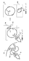
本実施形態における画像処理の概念図を図3に示す。図3(a)に示すように、位置A(a,b,c)は、目的部位12の正面像を撮影する位置であるが、位置A(a,b,c)では、障害物13が3次元超音波画像に表示されてしまう。そこで、超音波探触子2を位置B(a',b',c')に設置し、目的部位12に対して超音波を走査する。超音波探触子2と目的部位12の間には障害物13が介在しないため、走査によって得られた3次元超音波画像データ14は障害物13を含まない。このように超音波探触子2を位置B(a',b',c')に設置して再構成を行うと、目的部位12の側面像が表示される。
A conceptual diagram of image processing in the present embodiment is shown in FIG. As shown in FIG. 3 (a), the position A (a, b, c) is a position where a front image of the
そこで、位置情報解析部6内のメモリ61は、位置センサ4より得られる超音波探触子2の位置を記憶し、位置情報解析部6内の演算部62は、メモリ61に記憶された位置A(a,b,c)と位置B(a',b',c')の位置関係を解析する。超音波画像構成部7内の画像処理演算部72は、この位置関係に基づいて、位置B(a',b',c')から得られる3次元超音波画像データを位置A(a,b,c)となるよう画像変換し、3次元超音波画像を構成する。なお、位置B(a',b',c')はメモリ61に記憶されていてもよい。
Therefore, the
具体的には、位置情報解析部6内の演算部62は、超音波探触子2の位置A(a,b,c)を3次元超音波画像の表示位置となる変換行列として設定する。そして、演算部62は、超音波探触子2の方向を変化させた後の位置B(a',b',c')の変換行列を設定する。そして、位置A(a,b,c)と位置B(a',b',c')の変換行列から回転立体角度の変化量(補正パラメータ)を算定する。画像処理演算部72は補正パラメータに基づいて3次元超音波画像の座標変換を行い、3次元超音波画像の表示方向を変える。
Specifically, the
ここで、位置情報解析部6における補正パラメータの算出方法について説明する。位置センサ4の基準軸より、位置A(a,b,c)の超音波探触子2の位置と方向を示す変換行列Sを式(1)、位置B(a',b',c')の超音波探触子2の位置と方向を示す変換行列Dを式(2)とする。この変換行列はメモリ61に記憶されている。そして、演算部62は、超音波探触子2において任意に決定された位置A(a,b,c)において3次元超音波画像データ14に対する回転行列Vを式(3)とすると、位置A(a,b,c)から、位置B(a',b',c')への変換行列Xは、式(5)より、式(6)として設定する。したがって、式(4)で表される補正パラメータM,変換行列X,回転行列Vの関係は式(7)の通りになる。
Here, a correction parameter calculation method in the position information analysis unit 6 will be described. From the reference axis of the position sensor 4, a transformation matrix S indicating the position and direction of the
ここで、簡便化のため、回転成分から表示角度補正のみを行う場合には、式(1)中、(ds1, ds2, ds3)=(0,0,0)、式(2)中、(dv1, dv2, dv3)=(0,0,0)、式(3)中、(dd1,dd2,dd3)=(0,0,0)とする。 Here, for the sake of simplicity, when only the display angle correction is performed from the rotation component, (ds1, ds2, ds3) = (0, 0, 0) in equation (1), dv1, dv2, dv3) = (0, 0, 0), and in formula (3), (dd1, dd2, dd3) = (0, 0, 0).
したがって、補正パラメータMは式(8)により演算部62で算定される。すなわち、超音波探触子2の位置B(a',b',c')で得られた3次元超音波画像データ14は、補正パラメータMで表される座標変換を用い、3次元超音波画像の中央を原点として回転される。画像処理演算部72はこの回転した3次元超音波画像を再構成することにより、位置A(a,b,c)の方向からの3次元超音波画像を得ることができる。

図4に位置補正パラメータの算定を行うための手順を示す。超音波検査が開始された後、位置情報解析部6内の演算部62は、現在の超音波探触子2の位置を示す変換行列Dの更新(S100)を行い、コントロールパネル10より入力される回転行列Vの更新(S101)を行う。そして、位置A(a,b,c)に合わせて位置B(a',b',c')で得られる3次元超音波画像を補正する、つまり表示補正機能がオンになっている場合(S102)、移動前(位置A(a,b,c))の超音波探触子2の位置を示す変換行列S を固定し、変換行列Dを可変するよう設定する(S103')。つまり変換行列S≠変換行列Dとなる。そして、超音波画像構成部7内の画像処理演算部72において(S104)で算定した補正パラメータMによる座標変換を用いて、3次元超音波画像を作成し、ディスプレイ8で表示する。制御部9において検査終了が選択されていなければ、処理(S100)から再び行い、検査終了が選択されていれば処理を終了する(S106)。
FIG. 4 shows the procedure for calculating the position correction parameter. After the ultrasonic inspection is started, the
なお、本発明を適用しない場合は、表示位置を位置A(a,b,c)に合わせて3次元超音波画像を補正しない。すなわち表示補正機能がオンになっていない場合(S102)、位置情報解析部6内の演算部62は、移動前(位置A(a,b,c))の超音波探触子2の位置を示す変換行列Sに変換行列Dを代入(S103)し、補正パラメータMを上記式より算定する(S104)。この時、変換行列S=変換行列Dであるため、補正パラメータMはコントロールパネル10より入力された回転行列Vのみを行う変換行列となる。
When the present invention is not applied, the three-dimensional ultrasonic image is not corrected by matching the display position with the position A (a, b, c). That is, when the display correction function is not turned on (S102), the
コントロールパネル10より表示補正機能がオンに操作された場合(S102)、移動前(位置A(a,b,c))の超音波探触子2の位置を示す変換行列Sが更新されないため、処理(S104)において算定される補正パラメータMは、現在の超音波探触子2の位置を表す変換行列Dから、移動前の超音波探触子2の位置A(a,b,c)を示す変換行列Sへの移動に加え、コントロールパネル10より入力された回転行列Vを行う変換行列となる。すなわち、前述の補正パラメータMは、現在の超音波探触子2の位置B(a',b',c')において走査した3次元超音波画像データを、位置A(a,b,c)の超音波探触子2の位置にて走査した3次元超音波画像データに対しコントロールパネル10より入力された回転行列Vによる座標変換を行った場合の表示方向と同一の位置から、3次元超音波画像を再構成するものになる。現在の超音波探触子2の位置B(a',b',c')を表す変換行列Dは走査毎に更新されるが、移動前の超音波探触子2の位置A(a,b,c)を示す変換行列Sは、表示補正オンがなされている間は更新されないことから、現在の超音波探触子2の位置B(a',b',c')に関わらず、常に移動前の超音波探触子2の位置A(a,b,c)において観察した場合の表示状態を保持することができる。
When the display correction function is turned on from the control panel 10 (S102), since the transformation matrix S indicating the position of the
このように位置情報解析部6内の演算部62は、超音波探触子2の位置A(a,b,c)と位置B(a',b',c')における位置情報より、3次元超音波画像データ14を回転させ、位置A(a,b,c)における3次元超音波画像と同じ画像を得るための補正パラメータを算定する。そして、超音波画像構成部7内の画像処理演算部72は、3次元超音波画像データ14に対し、この補正パラメータを用いて再構成を行うことで自動的に3次元超音波画像を得る。
As described above, the
ここで、3次元超音波画像データ14を回転変換する他の形態について説明する。まず、位置情報解析部6内のメモリ61は、目的部位12の正面像を表示させ、表示位置としての位置A(a,b,c)を記憶する。そして、メモリ61は、超音波画像に障害物13が含まない位置B(a',b',c')を記憶する。これらの位置情報は、位置情報解析部6内の演算部62へ送られ、演算部62は位置A(a,b,c)に対する位置B(a',b',c')の位置の変化量及び回転立体角の変位量を算出する。そして、画像処理演算部72は、その変化した超音波探触子2の位置と角度分だけ3次元超音波画像を回転させ、位置A(a,b,c)が表示位置となるよう3次元超音波画像を表示する。
Here, another mode for rotationally converting the three-dimensional
具体的には位置A(a,b,c)で表示される平面画像の法線ベクトルと、位置B(a',b',c')で表示される平面画像の法線ベクトルは、3次元超音波画像データ上で交わっている場合、交点を中心とした回転立体角の変位量である。この変位量は、X軸の回りの回転と、Y軸の回りの回転と、Z軸の周りの回転に分解され、それぞれの回転は次に表す回転行列で表現される。 Specifically, the normal vector of the planar image displayed at the position A (a, b, c) and the normal vector of the planar image displayed at the position B (a ′, b ′, c ′) are 3 When intersecting on the two-dimensional ultrasonic image data, the amount of displacement of the rotation solid angle around the intersection. This displacement amount is decomposed into rotation around the X axis, rotation around the Y axis, and rotation around the Z axis, and each rotation is expressed by a rotation matrix shown below.
先ず、X軸の周りの角度θ1の回転は、
このように、第1の実施形態によると、超音波探触子2の位置A(a,b,c)と位置B(a',b',c')の位置関係に基づいて、画像処理演算部72が位置B(a',b',c')から得られる3次元超音波画像データを変換することにより、位置A(a,b,c)からの表示方向で3次元超音波画像を表示させることができる。つまり、一旦、超音波探触子2の或る位置を指定すれば、超音波探触子2を移動させてもその位置から見た3次元超音波画像を表示させることができる。
Thus, according to the first embodiment, image processing is performed based on the positional relationship between the position A (a, b, c) and the position B (a ′, b ′, c ′) of the
また、超音波探触子2を手ぶれ等があったとしても、すなわち位置B(a',b',c')から得られる3次元超音波画像データに変化があったとしても、位置A(a,b,c)は固定されているため、位置A(a,b,c)の位置から安定して3次元超音波画像を表示させることができる。
Further, even if the
次に第2の実施形態を図5に示す。第1の実施形態と異なる点は、表示位置を示す方向指示マーク30を3次元的に表示させ、その方向指示マーク30に対応した目的部位12を表示する点である。ディスプレイ8には、3次元超音波画像と補助画面81が表示される。補助画面81は、超音波探触子2を当接した位置B(a',b',c')から見た3次元超音波画像と、表示方向を示す方向指示マーク30が表示されている。この方向指示マーク30は、コントロールパネル10を用いて、目的部位12の周囲を3次元的に移動される。なお、方向指示マーク30は、目的部位12の中心点を向いている。
Next, a second embodiment is shown in FIG. The difference from the first embodiment is that the
ここで、方向指示マーク30の位置を位置C(a”,b”,c”):表示位置とする。図5の方向指示マーク30は、目的部位12を下方から撮影する位置である。位置情報解析部6内の演算部62は、上記第1の実施形態と同じ方式で、位置C(a”,b”,c”)に対する位置B(a',b',c')の位置の補正パラメータを算出したり、変化量及び回転立体角の変位量を算出する。そして、画像処理演算部72は、回転した3次元超音波画像を構成し、位置C(a”,b”,c”)つまり方向指示マーク30方向からの3次元超音波画像をディスプレイ8に表示させる。よって、設定した方向指示マーク30方向からの3次元超音波画像を観察することができる。
Here, the position of the
また、超音波探触子2を被検体50に固定した状態で、コントロールパネル10を用いて、方向指示マーク30を移動させる。この方向指示マーク30の移動に伴い、位置情報解析部6内の演算部62はリアルタイムに位置の変化量及び回転立体角の変位量を算出する。そして、位置の変化量及び回転立体角の変位量に基づいて、回転した3次元超音波画像をリアルタイムに構成することにより、方向指示マーク30の向きの3次元超音波画像を常にディスプレイ8に表示することができる。第2次実施形態によると、方向指示マーク30の向きによる3次元超音波画像の調整を行うことができる。
Further, the
次に第3の実施形態を図6に示す。第1の実施形態及び第2の実施形態と異なる点は、3次元超音波画像とBモード像を同時に表示する点である。このBモード像は超音波探触子2の走査方向から撮影したものである。
Next, a third embodiment is shown in FIG. The difference from the first embodiment and the second embodiment is that a three-dimensional ultrasound image and a B-mode image are displayed simultaneously. This B-mode image is taken from the scanning direction of the
破線15は、ディスプレイ8に表示される3次元超音波画像に対応するBモード像のスライス面である。破線15は、コントロールパネル10により移動させることができ、破線15の位置情報を位置情報解析部6が認識し、超音波画像構成部7内の画像処理演算部72は3次元超音波画像データ14から破線15に対応した断面のBモード像を選択してディスプレイ8に表示する。このように、被検体50の外周面と内部を同時に表示することができ、Bモード像を観察したい時も適宜変更することができる。よって、第3の実施形態によると、超音波探触子2の位置A(a,b,c)と位置B(a',b',c')の位置関係に基づいて、位置B(a',b',c')から得られる3次元超音波画像データを変換することにより、位置A(a,b,c)からの表示方向で2次元超音波画像を表示させることができる。つまり、一旦、超音波探触子2の或る位置を指定すれば、超音波探触子2を移動させてもその位置から見た2次元超音波画像を表示させることができる。
なお、破線15の初期設定は、超音波探触子2の走査面としているが、上記の位置A(a,b,c)、位置B(a',b',c')、位置C(a”,b”,c”)や方向指示マーク30に追従させてもよい。A
The initial setting of the
次に第4の実施形態を図3を用いて説明する。第1〜第3の実施形態と異なる点は、2以上の3次元超音波画像を合成する点である。
位置B(a',b',c')から超音波を走査して得る3次元超音波画像データ14は、超音波探触子2側の3次元超音波画像データは充分であるが、位置B(a',b',c')の点対称である裏側の3次元超音波画像データが不足している。図3では、超音波探触子2が当接される右耳側の3次元超音波画像データは充分であるが、目的部位12の左耳側の3次元超音波画像データが不足している。そこで、3次元超音波画像データが不足している側の3次元超音波画像データ14を予めメモリ71に記憶させておき、画像処理演算部72はメモリ71に記憶された3次元超音波画像とリアルタイムに取得される3次元超音波画像を合成する。Next, a fourth embodiment will be described with reference to FIG. The difference from the first to third embodiments is that two or more three-dimensional ultrasonic images are synthesized.
The 3D
具体的に、この合成する機能について説明する。超音波画像構成部7内の画像処理演算部72は、2つ以上の3次元超音波画像を合成する機能を有している。まず、被検体50に超音波を走査し3次元超音波画像を取得し、メモリ71に記憶させる。この際、位置センサ4の位置情報から3次元超音波画像の基準点を設定し、その基準点をメモリ71に記憶させる。そして、超音波探触子2の位置を変え、被検体50に超音波を走査し、リアルタイムに3次元超音波画像を取得する。次に、画像処理演算部72は、メモリ71に記憶された3次元超音波画像の基準点と、リアルタイムに3次元超音波画像の基準点を合わせて、記憶された3次元超音波画像とリアルタイムの3次元超音波画像を重ね合わせる。2つ以上の3次元超音波画像を重ね合わせる際、輝度が大きい3次元超音波画像を優先的に表示させる。なお、重ね合わせる3次元超音波画像は3つ以上でもよい。
Specifically, the function to be synthesized will be described. The image
このように、メモリ71は、予め不足する側の3次元超音波画像データを記憶させ、画像処理演算部72は、その3次元超音波画像データを用いてリアルタイム3次元超音波画像を補正する。よって、第4の実施形態によると、どの角度でも均一輝度の3次元超音波画像を表示させることができる。
As described above, the
次に第5の実施形態を図7を用いて説明する。第1〜第4の実施形態と異なる点は、3次元超音波画像データを部分的に削除するプリカットラインを設定する点である。 Next, a fifth embodiment will be described with reference to FIG. The difference from the first to fourth embodiments is that a precut line for partially deleting the three-dimensional ultrasonic image data is set.
左図31は、ディスプレイ8に表示されるプリカット設定画面に関する図である。右図32は、超音波画像構成部7内の画像処理演算部72で行われる3次元超音波画像データ処理に関するイメージ図である。超音波探触子2の位置A(a,b,c)から取得される3次元超音波画像データは、設定されたROI35で指定された範囲内の3次元超音波画像データである。つまり、このROI35は立体的な領域を持っている。そして、3次元超音波画像データには、胎児36に関する3次元超音波画像データと、胎盤33に関する3次元超音波画像データを含まれている。ROI35内に胎盤33に関する3次元超音波画像データを削除するプリカットライン34を設定する。プリカットライン設定画面31に示されるように、胎盤33と胎児36の間にプリカットライン34が配置される。このプリカットライン34の設定は、コントロールパネル10を介して行われる。
FIG. 31 on the left is a diagram related to the precut setting screen displayed on the
プリカットライン34が設定されると、3次元超音波画像データは、プリカットライン34を境界にして2つの領域に区切られる。具体的に、3次元超音波画像データは、プリカットライン34を軸にして、3次元超音波画像データの表面に対して垂直方向に領域が立体的に区切られる。そして、このように区切られた2つの領域のうち、一方の3次元超音波画像データが削除され、もう一方の3次元超音波画像データが残る。本実施形態の場合、横方向ラインが付与された胎盤33側の3次元超音波画像データ領域38は削除され、胎児36側の3次元超音波画像データ領域37が残る。この3次元超音波画像データ領域37の設定ついては、コントロールパネル10を介して手動で領域を選択し、選択された方を残す領域37と設定し、もう一方を削除する領域38として設定する。また、画像処理演算部72は、体積が少ない3次元超音波画像データの方を自動的に削除するという設定をしてもよい。画像処理演算部72は領域37内の3次元超音波画像データを用いて、ボクセル法又はボリュームレンダリング法などの手法によって3次元超音波画像を再構成する。そして、3次元超音波画像をディスプレイ8に表示する。
When the
超音波探触子2の位置D(A,B,C)から取得される3次元超音波画像データに対しても、超音波探触子2の位置A(a,b,c)のプリカットライン34の位置をメモリ71に記憶させておき、灰色に色付けされた胎盤33側の3次元超音波画像データ領域38を削除し、胎児36側の3次元超音波画像データ領域37を残させ、画像処理演算部72は3次元超音波画像データ領域37における3次元超音波画像をディスプレイ8に表示させる。
The pre-cut line at the position A (a, b, c) of the
具体的には、超音波画像構成部7内の画像処理演算部72は超音波探触子2の位置A(a,b,c)で設定されるプリカットライン34の位置を超音波探触子2の位置A(a,b,c)に対応させてメモリ71に記憶させる。また、プリカットライン34で削除される3次元超音波画像データの方向をメモリ71に記憶させる。そして、超音波探触子2を位置D(A,B,C)に移動させて、位置D(A,B,C)における3次元超音波画像データを得る。この位置D(A,B,C)における3次元超音波画像データに対し、位置A(a,b,c)で設定したプリカットライン34の位置とプリカットライン34で削除される3次元超音波画像データの方向をメモリ71から読み出し対応させる。詳細に説明すると、位置D(A,B,C)における3次元超音波画像データに対し、超音波探触子2の位置A(a,b,c)におけるプリカットライン34の位置を読み出し設定する。プリカットライン34の位置はメモリ71に記憶されているため、超音波探触子2の移動量及び角度に対応させても、削除される3次元超音波画像データ領域は胎盤33側である。
Specifically, the image
このように位置D(A,B,C)において設定されたプリカットライン34に基づいて3次元超音波画像データが削除される方向を定めて、灰色に色付けされた胎盤33側の3次元超音波画像データ領域38は削除され、胎児36側の3次元超音波画像データ領域37が残る。そして、位置D(A,B,C)における領域37内の3次元超音波画像データを用いて、ボクセル法又はボリュームレンダリング法などの手法によって3次元超音波画像に再構成する。そして、位置D(A,B,C)における3次元超音波画像がディスプレイ8に表示される。
In this way, the direction in which the 3D ultrasound image data is deleted is determined based on the
超音波探触子2の位置A(a,b,c)で撮影する3次元超音波画像は、胎盤33等の障害物を通過して超音波を送受信するが、位置D(A,B,C)で超音波を送受信する経路、超音波探触子2と胎児との間に胎盤33等の障害物が無い。つまり、第5の実施形態によると、超音波探触子2の位置A(a,b,c)で撮影する3次元超音波画像よりも、位置D(A,B,C)で撮影する3次元超音波画像の方が、超音波送受信における胎盤33等の障害物が無いため、よりクリアな3次元超音波画像を表示させることができる。
The 3D ultrasound image taken at the position A (a, b, c) of the
なお、上記第1〜5の実施形態は組み合わせて実施でき、操作者は任意に選択して実施することもできる。また、超音波画像構成部7は超音波受信信号の一種であるドプラ信号から血流画像を構成してもよい。そして、3次元超音波画像と血流画像の3次元画像とを別個に再構成し、Bモード画像と血流画像とを3次元画像上で合成したり、あるいは並列表示したりしてもよい。
The first to fifth embodiments can be implemented in combination, and the operator can arbitrarily select and implement them. Further, the ultrasonic
Claims (20)
前記超音波探触子の位置を検出する位置センサと、前記位置センサより得られる前記超音波探触子の第1の位置を記憶し、前記超音波探触子の前記第1の位置と第2の位置との間の位置の変化量及び回転立体角度の変化量に基づいて前記第1の位置と前記第2の位置との位置関係を解析する位置情報解析部とを備え、
前記超音波画像構成部は、前記第2の位置で取得した3次元超音波画像データを前記位置関係に基づいて前記第1の位置における3次元超音波画像となるように変換し、前記第1の位置における前記3次元超音波画像を構成することを特徴とする超音波診断装置。An ultrasonic probe that transmits and receives ultrasonic waves to and from a subject, and an ultrasonic image forming unit that forms a three-dimensional ultrasonic image from three-dimensional ultrasonic image data based on an ultrasonic signal received from the ultrasonic probe And in an ultrasonic diagnostic apparatus comprising a display unit for displaying the three-dimensional ultrasonic image,
A position sensor for detecting a position of the ultrasonic probe; a first position of the ultrasonic probe obtained from the position sensor; and a first position and a first position of the ultrasonic probe. and a position information analysis unit for analyzing a positional relationship between the first position and the second position based on the change amount and the change amount of the rotational solid angle position between the second position,
The ultrasonic image construction unit converts the three-dimensional ultrasonic image data acquired at the second position to be a three-dimensional ultrasonic image at the first position based on the positional relationship, and the first An ultrasonic diagnostic apparatus comprising the three-dimensional ultrasonic image at the position of.
前記超音波画像構成部は、前記表示補正機能のオンの場合に、前記第1の位置で取得した3次元超音波画像データを前記位置関係と同一になるように前記第2の位置における3次元超音波画像を変換し、該変換された第2の位置における前記3次元超音波画像を構成することを特徴とする請求項1記載の超音波診断装置。When the display correction function is on, the ultrasonic image constructing unit is configured so that the three-dimensional ultrasonic image data acquired at the first position is the same as the three-dimensional position at the second position. 2. The ultrasonic diagnostic apparatus according to claim 1, wherein an ultrasonic image is converted, and the three-dimensional ultrasonic image at the converted second position is constructed.
前記超音波探触子を第1の位置に設定して第1の位置を記憶するステップと、前記超音波探触子を第2の位置に設定して3次元超音波画像データを取得するステップと、前記超音波探触子の前記第1の位置と前記第2の位置との間の位置の変化量及び回転立体角度の変化量に基づいて前記3次元超音波画像データを前記第1の位置における3次元超音波画像となるように変換するステップと、該変換した前記3次元超音波画像を構成して表示するステップとを含むことを特徴とする超音波診断装置の作動方法。 An ultrasonic probe that transmits and receives ultrasonic waves to and from a subject, and an ultrasonic image forming unit that forms a three-dimensional ultrasonic image from three-dimensional ultrasonic image data based on an ultrasonic signal received from the ultrasonic probe And in the operating method of the ultrasonic diagnostic apparatus comprising a display unit for displaying the three-dimensional ultrasonic image,
Step wherein the obtaining and storing the first position by setting the ultrasonic probe to the first position, the ultrasonic probe of the 3-dimensional ultrasound image data set to the second position And the three-dimensional ultrasonic image data based on the amount of change in position and the amount of change in rotational solid angle between the first position and the second position of the ultrasonic probe . A method for operating an ultrasonic diagnostic apparatus, comprising: converting a position into a three-dimensional ultrasonic image at a position; and constructing and displaying the converted three-dimensional ultrasonic image.
Priority Applications (1)
| Application Number | Priority Date | Filing Date | Title |
|---|---|---|---|
| JP2007502633A JP4785149B2 (en) | 2005-02-09 | 2006-02-09 | Ultrasonic diagnostic apparatus and operation method thereof |
Applications Claiming Priority (4)
| Application Number | Priority Date | Filing Date | Title |
|---|---|---|---|
| JP2005032477 | 2005-02-09 | ||
| JP2005032477 | 2005-02-09 | ||
| JP2007502633A JP4785149B2 (en) | 2005-02-09 | 2006-02-09 | Ultrasonic diagnostic apparatus and operation method thereof |
| PCT/JP2006/302235 WO2006085571A1 (en) | 2005-02-09 | 2006-02-09 | Ultrasonographic device and ultrasonographic method |
Publications (2)
| Publication Number | Publication Date |
|---|---|
| JPWO2006085571A1 JPWO2006085571A1 (en) | 2008-06-26 |
| JP4785149B2 true JP4785149B2 (en) | 2011-10-05 |
Family
ID=36793142
Family Applications (1)
| Application Number | Title | Priority Date | Filing Date |
|---|---|---|---|
| JP2007502633A Expired - Fee Related JP4785149B2 (en) | 2005-02-09 | 2006-02-09 | Ultrasonic diagnostic apparatus and operation method thereof |
Country Status (6)
| Country | Link |
|---|---|
| US (1) | US8617075B2 (en) |
| EP (1) | EP1847222B1 (en) |
| JP (1) | JP4785149B2 (en) |
| CN (1) | CN101102721B (en) |
| DE (1) | DE602006021274D1 (en) |
| WO (1) | WO2006085571A1 (en) |
Families Citing this family (34)
| Publication number | Priority date | Publication date | Assignee | Title |
|---|---|---|---|---|
| US11627944B2 (en) | 2004-11-30 | 2023-04-18 | The Regents Of The University Of California | Ultrasound case builder system and method |
| KR100880125B1 (en) * | 2005-10-17 | 2009-01-23 | 주식회사 메디슨 | Image processing system and method for forming 3-dimension images using multiple sectional plane images |
| CN101925326B (en) * | 2007-12-03 | 2012-09-26 | 睿捕心脏股份公司 | State machine user and validation interface system |
| JP5182932B2 (en) * | 2008-06-18 | 2013-04-17 | 独立行政法人国立成育医療研究センター | Ultrasonic volume data processor |
| US8172753B2 (en) * | 2008-07-11 | 2012-05-08 | General Electric Company | Systems and methods for visualization of an ultrasound probe relative to an object |
| JP5835903B2 (en) * | 2011-02-03 | 2015-12-24 | 株式会社東芝 | Ultrasonic diagnostic equipment |
| US9342922B2 (en) | 2011-08-19 | 2016-05-17 | Hitachi Medical Corporation | Medical imaging apparatus and method of constructing medical images |
| EP2754396A4 (en) * | 2011-09-08 | 2015-06-03 | Hitachi Medical Corp | Ultrasound diagnostic device and ultrasound image display method |
| JP2013111327A (en) * | 2011-11-30 | 2013-06-10 | Sony Corp | Signal processing device and method |
| US20130150719A1 (en) * | 2011-12-08 | 2013-06-13 | General Electric Company | Ultrasound imaging system and method |
| CN103197000A (en) * | 2012-01-05 | 2013-07-10 | 西门子公司 | Apparatus and monitoring device used in ultrasonic detection, and ultrasonic detection system and method |
| KR101386102B1 (en) * | 2012-03-09 | 2014-04-16 | 삼성메디슨 주식회사 | Method for providing ultrasound images and ultrasound apparatus thereof |
| JP6037447B2 (en) * | 2012-03-12 | 2016-12-07 | 東芝メディカルシステムズ株式会社 | Ultrasonic diagnostic equipment |
| US11631342B1 (en) | 2012-05-25 | 2023-04-18 | The Regents Of University Of California | Embedded motion sensing technology for integration within commercial ultrasound probes |
| US9958420B2 (en) * | 2013-02-06 | 2018-05-01 | Bwxt Technical Services Group, Inc. | Synthetic data collection method for full matrix capture using an ultrasound array |
| JP2014161444A (en) * | 2013-02-22 | 2014-09-08 | Toshiba Corp | Ultrasound diagnostic device, medical image processor and control program |
| EP2979643B1 (en) * | 2013-03-25 | 2017-10-25 | Hitachi, Ltd. | Ultrasonic imaging device and ultrasonic image display method |
| US10380919B2 (en) | 2013-11-21 | 2019-08-13 | SonoSim, Inc. | System and method for extended spectrum ultrasound training using animate and inanimate training objects |
| KR102329113B1 (en) * | 2014-10-13 | 2021-11-19 | 삼성전자주식회사 | An ultrasonic imaging apparatus and a method for controlling the same |
| CN104287777B (en) * | 2014-10-17 | 2017-09-26 | 苏州佳世达电通有限公司 | Ultrasound scanning method and ultrasound scanning system |
| KR102388130B1 (en) | 2015-01-12 | 2022-04-19 | 삼성메디슨 주식회사 | Apparatus and method for displaying medical image |
| CN105982693A (en) * | 2015-01-27 | 2016-10-05 | 中慧医学成像有限公司 | Imaging method |
| US11600201B1 (en) * | 2015-06-30 | 2023-03-07 | The Regents Of The University Of California | System and method for converting handheld diagnostic ultrasound systems into ultrasound training systems |
| CN106846445B (en) * | 2016-12-08 | 2019-08-27 | 华中科技大学 | A kind of three-dimensional ultrasound pattern object plotting method based on CPU |
| US10896628B2 (en) | 2017-01-26 | 2021-01-19 | SonoSim, Inc. | System and method for multisensory psychomotor skill training |
| WO2018205274A1 (en) * | 2017-05-12 | 2018-11-15 | 深圳迈瑞生物医疗电子股份有限公司 | Ultrasonic device, and method and system for transforming display of three-dimensional ultrasonic image thereof |
| CN107102335B (en) * | 2017-06-20 | 2023-09-05 | 河北工业大学 | Ultrasonic three-dimensional imaging device |
| CN107582098B (en) * | 2017-08-08 | 2019-12-06 | 南京大学 | three-dimensional ultrasonic imaging method for two-dimensional ultrasonic image set reconstruction |
| CN107578662A (en) * | 2017-09-01 | 2018-01-12 | 北京大学第医院 | A kind of virtual obstetric Ultrasound training method and system |
| WO2020093402A1 (en) * | 2018-11-09 | 2020-05-14 | 深圳迈瑞生物医疗电子股份有限公司 | Ultrasound image acquisition method, system and computer storage medium |
| US11810473B2 (en) | 2019-01-29 | 2023-11-07 | The Regents Of The University Of California | Optical surface tracking for medical simulation |
| US11495142B2 (en) | 2019-01-30 | 2022-11-08 | The Regents Of The University Of California | Ultrasound trainer with internal optical tracking |
| CN111358492A (en) * | 2020-02-28 | 2020-07-03 | 深圳开立生物医疗科技股份有限公司 | Four-dimensional contrast image generation method, device, equipment and storage medium |
| CN112617902A (en) * | 2020-12-31 | 2021-04-09 | 上海联影医疗科技股份有限公司 | Three-dimensional imaging system and imaging method |
Citations (1)
| Publication number | Priority date | Publication date | Assignee | Title |
|---|---|---|---|---|
| JPH0747064A (en) * | 1993-08-05 | 1995-02-21 | Hitachi Medical Corp | Ultrasonic diagnostic system |
Family Cites Families (23)
| Publication number | Priority date | Publication date | Assignee | Title |
|---|---|---|---|---|
| JPH0744932B2 (en) * | 1990-10-24 | 1995-05-17 | アロカ株式会社 | Ultrasonic image display device |
| US5608849A (en) * | 1991-08-27 | 1997-03-04 | King, Jr.; Donald | Method of visual guidance for positioning images or data in three-dimensional space |
| US5842473A (en) * | 1993-11-29 | 1998-12-01 | Life Imaging Systems | Three-dimensional imaging system |
| JPH09508994A (en) * | 1994-01-28 | 1997-09-09 | シュナイダー メディカル テクノロジーズ インコーポレイテッド | Image forming apparatus and method |
| JP3407169B2 (en) * | 1995-10-12 | 2003-05-19 | 富士写真光機株式会社 | Ultrasonic image stereoscopic display device and ultrasonic image stereoscopic display method |
| US6167296A (en) * | 1996-06-28 | 2000-12-26 | The Board Of Trustees Of The Leland Stanford Junior University | Method for volumetric image navigation |
| KR20000069171A (en) * | 1996-11-29 | 2000-11-25 | 라이프 이미징 시스템즈 인코퍼레이티드 | Enhanced image processing for a three-dimensional imaging system |
| US5810008A (en) * | 1996-12-03 | 1998-09-22 | Isg Technologies Inc. | Apparatus and method for visualizing ultrasonic images |
| US6511426B1 (en) * | 1998-06-02 | 2003-01-28 | Acuson Corporation | Medical diagnostic ultrasound system and method for versatile processing |
| JP4068234B2 (en) | 1998-10-05 | 2008-03-26 | 株式会社東芝 | Ultrasonic diagnostic equipment |
| JP4443672B2 (en) * | 1998-10-14 | 2010-03-31 | 株式会社東芝 | Ultrasonic diagnostic equipment |
| US6174285B1 (en) * | 1999-02-02 | 2001-01-16 | Agilent Technologies, Inc. | 3-D ultrasound imaging system with pre-set, user-selectable anatomical images |
| JP3410404B2 (en) | 1999-09-14 | 2003-05-26 | アロカ株式会社 | Ultrasound diagnostic equipment |
| US6544178B1 (en) * | 1999-11-05 | 2003-04-08 | Volumetrics Medical Imaging | Methods and systems for volume rendering using ultrasound data |
| KR20020071377A (en) * | 2001-03-06 | 2002-09-12 | 마이크로소노 테크놀로지스 인코포레이티드 | Device for detecting 3 dimension image using positioning sensor |
| JP4088104B2 (en) | 2002-06-12 | 2008-05-21 | 株式会社東芝 | Ultrasonic diagnostic equipment |
| JP4276825B2 (en) * | 2002-10-01 | 2009-06-10 | オリンパス株式会社 | Ultrasonic diagnostic equipment |
| US7270634B2 (en) * | 2003-03-27 | 2007-09-18 | Koninklijke Philips Electronics N.V. | Guidance of invasive medical devices by high resolution three dimensional ultrasonic imaging |
| JP4855926B2 (en) * | 2003-06-03 | 2012-01-18 | コーニンクレッカ フィリップス エレクトロニクス エヌ ヴィ | Synchronizing swivel 3D ultrasonic display with vibration target |
| US7717849B2 (en) * | 2004-07-06 | 2010-05-18 | Gerneral Electric Company | Method and apparatus for controlling ultrasound system display |
| JP2008515517A (en) * | 2004-10-08 | 2008-05-15 | コーニンクレッカ フィリップス エレクトロニクス エヌ ヴィ | 3D diagnostic ultrasound imaging system with left-right reversal and upside-down image |
| US7452357B2 (en) * | 2004-10-22 | 2008-11-18 | Ethicon Endo-Surgery, Inc. | System and method for planning treatment of tissue |
| US8057394B2 (en) * | 2007-06-30 | 2011-11-15 | St. Jude Medical, Atrial Fibrillation Division, Inc. | Ultrasound image processing to render three-dimensional images from two-dimensional images |
-
2006
- 2006-02-09 JP JP2007502633A patent/JP4785149B2/en not_active Expired - Fee Related
- 2006-02-09 WO PCT/JP2006/302235 patent/WO2006085571A1/en active Application Filing
- 2006-02-09 US US11/815,657 patent/US8617075B2/en not_active Expired - Fee Related
- 2006-02-09 EP EP06713378A patent/EP1847222B1/en not_active Not-in-force
- 2006-02-09 DE DE602006021274T patent/DE602006021274D1/en active Active
- 2006-02-09 CN CN2006800023261A patent/CN101102721B/en not_active Expired - Fee Related
Patent Citations (1)
| Publication number | Priority date | Publication date | Assignee | Title |
|---|---|---|---|---|
| JPH0747064A (en) * | 1993-08-05 | 1995-02-21 | Hitachi Medical Corp | Ultrasonic diagnostic system |
Also Published As
| Publication number | Publication date |
|---|---|
| US8617075B2 (en) | 2013-12-31 |
| US20090209859A1 (en) | 2009-08-20 |
| WO2006085571A1 (en) | 2006-08-17 |
| CN101102721A (en) | 2008-01-09 |
| EP1847222B1 (en) | 2011-04-13 |
| DE602006021274D1 (en) | 2011-05-26 |
| CN101102721B (en) | 2010-04-14 |
| EP1847222A1 (en) | 2007-10-24 |
| EP1847222A4 (en) | 2010-03-03 |
| JPWO2006085571A1 (en) | 2008-06-26 |
Similar Documents
| Publication | Publication Date | Title |
|---|---|---|
| JP4785149B2 (en) | Ultrasonic diagnostic apparatus and operation method thereof | |
| EP3448264B1 (en) | 3d image compounding for ultrasound fetal imaging | |
| JP5283820B2 (en) | Method for expanding the ultrasound imaging area | |
| JP5400466B2 (en) | Diagnostic imaging apparatus and diagnostic imaging method | |
| JP6288996B2 (en) | Ultrasonic diagnostic apparatus and ultrasonic imaging program | |
| JP4632807B2 (en) | Ultrasonic diagnostic equipment | |
| CN106456112B (en) | Imaging system and method for positioning a 3D ultrasound volume in a desired orientation | |
| JP5525930B2 (en) | Ultrasound diagnostic device for generating and displaying 3D ultrasound images | |
| JP2006218210A (en) | Ultrasonic diagnostic apparatus, ultrasonic image generating program and ultrasonic image generating method | |
| US8348848B1 (en) | Methods and apparatus for ultrasound imaging | |
| JP2006271523A (en) | Ultrasonic diagnostic apparatus | |
| KR101120684B1 (en) | Ultrasound system and method for providing 3-dimensional ultrasound image based on roi of ellipsoid | |
| JP4297561B2 (en) | Opacity setting method, three-dimensional image forming method and apparatus, and ultrasonic imaging apparatus | |
| JP2011050742A (en) | Ultrasound system and method for providing ultrasound compound image considering steering angle | |
| JP2001079003A (en) | Ultrasonograph | |
| WO2016158467A1 (en) | Acoustic wave image generation device and method | |
| JP4543025B2 (en) | Ultrasonic diagnostic equipment | |
| KR102321853B1 (en) | Method and system for enhanced visualization of moving structures with cross-plane ultrasound images | |
| JP2015097687A (en) | Ultrasonic image processor | |
| KR101055528B1 (en) | Ultrasound system and method for providing OH | |
| JP2010158473A (en) | Ultrasonic image diagnostic apparatus | |
| JP5701362B2 (en) | Diagnostic imaging apparatus and diagnostic imaging method | |
| JP5182932B2 (en) | Ultrasonic volume data processor | |
| JP2011024827A (en) | Ultrasonograph | |
| JP2008048951A (en) | Ultrasonic diagnostic system |
Legal Events
| Date | Code | Title | Description |
|---|---|---|---|
| A621 | Written request for application examination |
Free format text: JAPANESE INTERMEDIATE CODE: A621 Effective date: 20090129 |
|
| A131 | Notification of reasons for refusal |
Free format text: JAPANESE INTERMEDIATE CODE: A131 Effective date: 20110425 |
|
| A521 | Written amendment |
Free format text: JAPANESE INTERMEDIATE CODE: A523 Effective date: 20110610 |
|
| TRDD | Decision of grant or rejection written | ||
| A01 | Written decision to grant a patent or to grant a registration (utility model) |
Free format text: JAPANESE INTERMEDIATE CODE: A01 Effective date: 20110706 |
|
| A01 | Written decision to grant a patent or to grant a registration (utility model) |
Free format text: JAPANESE INTERMEDIATE CODE: A01 |
|
| A61 | First payment of annual fees (during grant procedure) |
Free format text: JAPANESE INTERMEDIATE CODE: A61 Effective date: 20110708 |
|
| R150 | Certificate of patent or registration of utility model |
Free format text: JAPANESE INTERMEDIATE CODE: R150 Ref document number: 4785149 Country of ref document: JP Free format text: JAPANESE INTERMEDIATE CODE: R150 |
|
| FPAY | Renewal fee payment (event date is renewal date of database) |
Free format text: PAYMENT UNTIL: 20140722 Year of fee payment: 3 |
|
| S111 | Request for change of ownership or part of ownership |
Free format text: JAPANESE INTERMEDIATE CODE: R313111 |
|
| S533 | Written request for registration of change of name |
Free format text: JAPANESE INTERMEDIATE CODE: R313533 |
|
| R350 | Written notification of registration of transfer |
Free format text: JAPANESE INTERMEDIATE CODE: R350 |
|
| LAPS | Cancellation because of no payment of annual fees |