JP4784332B2 - Pulse radar equipment - Google Patents
Pulse radar equipment Download PDFInfo
- Publication number
- JP4784332B2 JP4784332B2 JP2006044104A JP2006044104A JP4784332B2 JP 4784332 B2 JP4784332 B2 JP 4784332B2 JP 2006044104 A JP2006044104 A JP 2006044104A JP 2006044104 A JP2006044104 A JP 2006044104A JP 4784332 B2 JP4784332 B2 JP 4784332B2
- Authority
- JP
- Japan
- Prior art keywords
- signal
- pulse
- distance
- target
- chirp frequency
- Prior art date
- Legal status (The legal status is an assumption and is not a legal conclusion. Google has not performed a legal analysis and makes no representation as to the accuracy of the status listed.)
- Expired - Fee Related
Links
- 230000005540 biological transmission Effects 0.000 claims description 59
- 238000012545 processing Methods 0.000 claims description 37
- 230000010355 oscillation Effects 0.000 claims description 21
- 238000012937 correction Methods 0.000 claims description 11
- 238000005259 measurement Methods 0.000 description 31
- 238000007906 compression Methods 0.000 description 22
- 230000006835 compression Effects 0.000 description 20
- 238000010586 diagram Methods 0.000 description 8
- 238000000034 method Methods 0.000 description 6
- 230000006866 deterioration Effects 0.000 description 3
- 238000005070 sampling Methods 0.000 description 2
- 238000007796 conventional method Methods 0.000 description 1
- 230000000694 effects Effects 0.000 description 1
Images
Landscapes
- Radar Systems Or Details Thereof (AREA)
Description
この発明は、ストレッチ処理パルス圧縮による測距あるいは測角を行うレーダ装置に関するものである。 The present invention relates to a radar apparatus that performs distance measurement or angle measurement by stretch processing pulse compression.
従来のストレッチ処理パルス圧縮による測距とビームフォーミングによる測角を行うレーダ装置では、ストレッチ処理パルス圧縮による測距を行った後に、距離毎にビームフォーミングによる測角を行っている(例えば、非特許文献1及び非特許文献2)。 Conventional radar devices that perform distance measurement by stretch processing pulse compression and angle measurement by beam forming perform angle measurement by beam forming for each distance after performing distance measurement by stretch processing pulse compression (for example, non-patent) Document 1 and Non-Patent Document 2).
上述の従来方法によれば、送信信号帯域が大きい場合に、レーダ装置から目標までの相対距離が大きい、あるいは送信パルス幅が小さいと、電波到来角の測定精度が劣化するという課題があった。 According to the conventional method described above, when the transmission signal band is large, if the relative distance from the radar device to the target is large or the transmission pulse width is small, the measurement accuracy of the radio wave arrival angle is deteriorated.
この発明は、上述の課題を解決するためになされたもので、その目的は、ストレッチ処理パルス圧縮による測距とビームフォーミングによる測角を行うレーダ装置において、送信信号帯域を大きくした場合に、レーダ装置から目標までの相対距離が大きい場合、あるいは、送信パルス幅が小さい場合であっても、測角精度の劣化を抑えることのできるレーダ装置を得るものである。 The present invention has been made in order to solve the above-described problems, and an object of the present invention is to provide a radar apparatus that performs distance measurement by stretch processing pulse compression and angle measurement by beam forming when the transmission signal band is increased. Even when the relative distance from the apparatus to the target is large, or even when the transmission pulse width is small, a radar apparatus capable of suppressing deterioration in angle measurement accuracy is obtained.
上述の課題を解決するため、この発明のパルスレーダ装置は、
チャープ周波数変調した送信パルスを送信する送信器と、
目標に反射された前記送信パルスを受信して受信信号を出力する複数の受信素子アンテナと、
前記送信器のチャープ周波数変調と同じ傾きでチャープ周波数変調された局部発振信号を発生する局部発振器と、
前記複数の受信素子アンテナが出力する受信信号を、前記局部発振信号を用いて位相検波し、前記受信信号の複素ビート信号をそれぞれ出力する受信器と、
前記複素ビート信号を時間方向にフーリエ変換し、前記目標までの相対距離情報を含む複数の高分解能レンジビン単位に分割された信号を出力するストレッチ処理パルス圧縮器と、
同じレンジビンの前記高分解能レンジビン単位に分割された信号を、空間方向にフーリエ変換することによってビーム形成し、形成したビームと前記複数の受信素子アンテナの配置と、前記チャープ周波数変調の傾きの情報と、前記相対距離情報に基づいて前記目標の方向を求めるビーム形成器と、
を備えたものである。
In order to solve the above-mentioned problem, the pulse radar device of the present invention is
A transmitter for transmitting a chirp frequency modulated transmission pulse;
A plurality of receiving antenna elements to output a received signal by receiving the transmission pulse reflected at the target,
A local oscillator that generates a chirp frequency modulated local oscillation signal with the same slope as the chirp frequency modulation of the transmitter;
Receivers that output the reception signals output by the plurality of reception element antennas using the local oscillation signals and output complex beat signals of the reception signals, respectively,
Stretch processing pulse compressor that Fourier-transforms the complex beat signal in the time direction and outputs a signal divided into a plurality of high-resolution range bin units including information on relative distance to the target;
The signal divided into the high-resolution range bin unit of the same range bin is formed into a beam by performing Fourier transform in the spatial direction, the formed beam, the arrangement of the plurality of receiving element antennas, and the information on the tilt of the chirp frequency modulation A beamformer for determining the direction of the target based on the relative distance information ;
It is equipped with .
これによって、この発明のパルスレーダによれば、ストレッチ処理パルス圧縮による測距と測角を行う際に、送信信号帯域を大きくしても、レーダ装置から目標までの相対距離が大きい場合や送信パルス幅が小さい場合にも測角精度を向上させることができる。 Thus, according to the pulse radar of the present invention, when ranging and angle measurement by stretch processing pulse compression is performed, even if the transmission signal band is increased, the relative distance from the radar device to the target is large or the transmission pulse The angle measurement accuracy can be improved even when the width is small.
以下、この発明の実施の形態について図を用いて説明する。 Embodiments of the present invention will be described below with reference to the drawings.
実施の形態1.
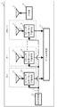
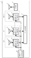
図1は、この発明の実施の形態1に係るパルスレーダ装置の構成を示すブロック図である。図において、パルスレーダ装置1は送信器10、送信アンテナ11および並列に配置されたパルス受信回路#0〜#N−1(Nは2以上の自然数)、さらには局部発振器15とビーム形成器17を備えている。
Embodiment 1 FIG.
FIG. 1 is a block diagram showing a configuration of a pulse radar apparatus according to Embodiment 1 of the present invention. In the figure, a pulse radar device 1 includes a
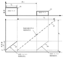
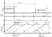
パルスレーダ装置1の送信器10は、図2の上段に示される振幅を時間変化させ、図2の下段に示される周波数変調方法で直線状に周波数が変化するようにチャープ変調した送信パルスを発生する。
The
ここで送信最小周波数をf0、パルス幅をTp、送信信号帯域をB0とする。チャープ変調の傾きはB0/Tpとなる。またパルス繰り返し周期は、目標との相対距離に相当する時間より十分に長く設定しているものとする。よって、送信信号Stx(t)は式(1)で表される。なお式中においてReは複素数の実部を表し、A1は送信信号の振幅、φ0は送信信号の初期位相を示す。

このようにして発生した送信パルスは送信アンテナ11から目標に照射される。目標までの距離をR、光速をcとすれば、目標によって反射されたパルスは2R/cの遅延時間を経て#0〜#N−1の各パルス受信回路における受信素子アンテナ12に到来する。
The transmission pulse generated in this way is irradiated from the transmission antenna 11 to the target. If the distance to the target is R and the speed of light is c, the pulse reflected by the target arrives at the
ここで、#0〜#N−1の各パルス受信回路における受信素子アンテナ12は等間隔で直線上に配列されているものとすれば、各受信素子アンテナが出力する受信信号13は式(2)で表されるSrx(n,t)で与えられる。
式(2)においてA2は受信信号の振幅を示し、ここでは、すべての受信素子アンテナで同じ振幅としている。さらに、Rs(n,θ)は、素子アンテナ間の電波伝搬の距離差を示し、式(3)で表される。なお式中において、dは素子アンテナ間隔、θは電波到来角である。
![]()
![]()
#0〜#N−1の各パルス受信回路において、アナログ受信信号13は同一のパルス受信回路内のストレッチ処理パルス圧縮手段14に入力される。その一方で、局部発振器15が発生した局部発振信号16が#0〜#N−1の各パルス受信回路のストレッチ処理パルス圧縮手段14に入力されるようになっている。ここで、局部発振信号16は図2に示されるように、時刻Tpにおいて送信最小周波数f0、帯域B1、変調時間TLで、送信パルスと同じ傾きB0/Tp=(B1/TL)で直線状に周波数が変化するチャープ信号であり、式(4)のL0(t)で表される。
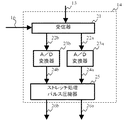
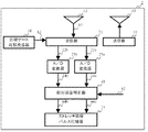
図3は、#0〜#N−1の各パルス受信回路におけるストレッチ処理パルス圧縮手段14の詳細な構成を示すブロック図である。図において、受信器21は局部発振信号16を用いて受信素子アンテナ12からの受信信号13を位相検波し、所定の帯域のみを通過させる帯域通過フィルタを通過させて得られる複素ビート信号22を得る。この複素ビート信号22は、式(5)のSb(n,t)として表される。
式(5)において、電波到来角θの関数であり、且つ、時間変数tの関数でない項(因数)が測角に関係する項である。よって式(5)において測角に関係する項は次のとおりとなる。
そのため、N個の受信素子アンテナでの受信信号を空間方向にフーリエ変換することによって、ビームフォーミングを行った結果の絶対値がピーク値となる空間周波数kapを求め、その後、式(8)から電波到来方向θを求めることができるというのが非特許文献1及び2に示された従来のストレッチ処理パルス圧縮方法であった。
この方法の問題点として、送信信号帯域B0が大きく、かつ、パルスレーダ装置から目標までの相対距離Rが大きい、あるいは送信パルス幅Tpが小さい場合には式(6)の値が光速cの2乗の値に比べて無視できなくなり、結果として、式(5)の6番目の項が近似的に1と見なすことができなくなることが挙げられる。すなわち、この場合、式(8)を用いて電波到来角を求めると、測角精度が劣化するのである。 As a problem of this method, when the transmission signal band B 0 is large and the relative distance R from the pulse radar apparatus to the target is large or the transmission pulse width T p is small, the value of the equation (6) is the light speed c. As a result, the sixth term of Equation (5) cannot be regarded as approximately 1 as a result. That is, in this case, when the radio wave arrival angle is obtained using the equation (8), the angle measurement accuracy is deteriorated.
そこで、この発明の実施の形態1におけるパルスレーダ装置1ではこのような近似に依らないストレッチ処理パルス圧縮処理を行う。 Therefore, the pulse radar device 1 according to Embodiment 1 of the present invention performs stretch processing pulse compression processing that does not depend on such approximation.
式(5)によって表される複素ビート信号22の実部22aは、A/D変換器23aに入力される。A/D変換器23aは入力された複素ビート信号22aをディジタル複素ビート信号24aに変換する。同様に、A/D変換器23bは複素ビート信号22の虚部22bをディジタル複素ビート信号24bに変換する。このようにして得られたディジタル複素ビート信号24は式(9)のSb(n,m)として表される。
ただし、ΔtはA/D変換機のサンプリング周期を、MはΔtでサンプリングした時のディジタル複素ビート信号の点数を、A′4は複素ビート信号の振幅を示す。 Here, Δt represents the sampling period of the A / D converter, M represents the number of digital complex beat signals when sampled at Δt, and A ′ 4 represents the amplitude of the complex beat signal.
ディジタル複素ビート信号24aとディジタル複素ビート信号24bはストレッチ処理パルス圧縮器25に入力される。ストレッチ処理パルス圧縮器25は、式(10)で示すように、時間方向へのフーリエ変換を行うことでストレッチ処理パルス圧縮処理を行い、目標までの相対距離情報を含む高分解能レンジビン単位あるいは高分解能レンジビン毎に分割された信号26を生成する。
式(10)において、2(R−Rp)>>Rs(n,θ)とすると、式(11)が成り立つときに高分解能レンジビン単位あるいは高分解能レンジビン毎に分割した信号Sr(n,kr)の絶対値がピーク値となることがわかる。
Sr(n,kr)の絶対値がピーク値となるレンジビン番号krをkrpとすると、Sr(n,kr)の絶対値のピークを検出することによってkrpを求め、求めたkrpを用いて式(12)より、パルスレーダ装置1と目標との相対距離Rcalを求めることができる。
また、その時の距離分解能ΔRは式(13)で表され、送信信号帯域B0を大きくすることによって、送信パルス幅に相当する距離分解能よりも高いM個の高分解能レンジビンを生成することができる。
ビーム形成器17では、ストレッチ処理パルス圧縮手段14で生成された高距離分解能レンジビンの中の目標の存在する高分解能レンジビンの信号を空間方向にフーリエ変換することにより、ビームフォーミングによる測角を行う。目標の存在する高距離分解能レンジビンkrpに対して、ビームフォーミングを行った場合、ビームフォーミング後の信号は式(14)で表される。
式(14)に式(3)を代入することによって、ビームフォーミング後の信号は式(15)で表される。
式(15)において、式(16)の条件が成立する場合では、式(17)が成り立つときにSa(ka,krp)の絶対値がピーク値となることがわかる。
Sa(ka,krp)の絶対値がピーク値となるkaをkapとすると、Sa(ka,krp)の絶対値のピークを検出することによってkapを求め、求めたkapを用いて式(18)より、電波到来角θに関する空間周波数sin(θ)を求めることができる。
よって、電波到来角θは式(19)によって求めることができる。
しかしながら、目標との相対距離Rの値が未知の場合、式(19)からθは求めることができない。そこで、ビーム形成器17は、目標との相対距離Rの代わりに式(12)で求めた目標との距離Rcalを用いることにより、式(20)により近似的に電波到来角θcalを求める。
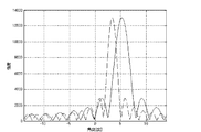
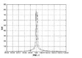
図4は、送信最小周波数f0を2.75GHz、送信信号帯域B0を500MHz、送信パルス幅Tpを4msec、パルスレーダ装置と目標との相対距離Rを1200km、受信素子アンテナ数Nを16、素子間隔dを0.2m、電波到来角θを5度として、式(8)を用いて求めた目標の角度θと、式(19)を用いて求めた目標の角度θcalとを図示したものである。図において、破線で示した波形は式(8)を用いたビームフォーミング結果、実線で示した波形は式(20)を用いたビームフォーミング結果である。このように、式(8)を用いて場合の角度が3.0度であるのに対し、式(20)を用いて求めた角度が5.2度となり、真値である5度により近い値が得られることが分かる。 FIG. 4 shows that the minimum transmission frequency f 0 is 2.75 GHz, the transmission signal band B 0 is 500 MHz, the transmission pulse width T p is 4 msec, the relative distance R between the pulse radar device and the target is 1200 km, and the number N of receiving element antennas is 16. The target angle θ obtained using the equation (8) and the target angle θcal obtained using the equation (19) are illustrated with the element interval d being 0.2 m and the radio wave arrival angle θ being 5 degrees. Is. In the figure, the waveform shown by the broken line is the beamforming result using the equation (8), and the waveform shown by the solid line is the beamforming result using the equation (20). In this way, the angle obtained using Equation (8) is 3.0 degrees, whereas the angle obtained using Equation (20) is 5.2 degrees, which is closer to the true value of 5 degrees. It can be seen that the value is obtained.
以上のような処理をすることによって、ストレッチ処理パルス圧縮による測距とビームフォーミングによる測角を行うレーダ装置において、送信信号帯域B0が大きく、かつ、パルスレーダ装置から目標までの相対距離Rが大きい、あるいは、送信パルス幅Tpが小さい場合であっても、測角精度の劣化が小さいレーダ装置を得ることができる。 By performing the above processing, in the radar apparatus that performs distance measurement by stretch processing pulse compression and angle measurement by beam forming, the transmission signal band B 0 is large, and the relative distance R from the pulse radar apparatus to the target is large, or even when the transmitted pulse width T p is small, it is possible to degrade the angle measuring accuracy obtained small radar device.
実施の形態2.
実施の形態1では、高距離分解能レンジビンSr(n,kr)の絶対値がピーク値となるレンジビン番号krを求め、このレンジビン番号からパルスレーダ装置1と相対距離Rcalを求めて、この距離を用いて電波到来角を計算した。
Embodiment 2. FIG.
In the first embodiment, the range bin number k r where the absolute value of the high-range resolution range bin S r (n, k r ) is the peak value is obtained, and the pulse radar device 1 and the relative distance R cal are obtained from the range bin number, The radio wave arrival angle was calculated using this distance.
しかし、これ以外にも例えば、距離分解能が式(13)で表されるM個の高分解能レンジビンを生成しておき、その時の各高分解能レンジビンまでの距離Rhr(kr)を式(21)によって求めて、この距離を用いて電波到来角を計算してもよい。
すなわち、実施の形態1のビーム形成器17において、ストレッチ処理パルス圧縮手段14から得た各高分解能レンジビン信号に対して、電波到来角θを求める場合に、未知の値である目標との相対距離Rの代わりに、式(21)で表される各高分解能レンジビンまでの距離Rhr(kr)を用いる。その結果得られる電波到来角θcalは次のようになる。
以上のような処理をすることによって、実施の形態1の効果に加え、ストレッチ処理パルス圧縮処理において、目標の存在する高分解能レンジビンが特定されない場合にでも、対応可能となる。 By performing the processing as described above, in addition to the effects of the first embodiment, even when the high resolution range bin where the target exists is not specified in the stretch processing pulse compression processing, it is possible to cope with it.
実施の形態3.
続いて、実施の形態1のパルスレーダ装置において、距離ゲートを設けることで局部発振信号の周波数帯域を小さく抑える構成について説明する。図5は、この発明の実施の形態3に係るパルスレーダ装置の構成を示すブロック図である。図において、距離ゲート局部発振器18は距離ゲートと呼ばれる周期毎に局部発振信号を繰り返し発生する局部発振器である。その他、図5において、図1と同一の符号を付した構成要素は実施の形態1と同様の構成を有している。またストレッチ処理パルス圧縮手段14の詳細な構成は実施の形態1と同様に、図3に示されている。
Embodiment 3 FIG.
Subsequently, in the pulse radar device of the first embodiment, a configuration that suppresses the frequency band of the local oscillation signal by providing a distance gate will be described. FIG. 5 is a block diagram showing the configuration of the pulse radar apparatus according to Embodiment 3 of the present invention. In the figure, a distance gate
次に、この実施の形態3に係るパルスレーダ装置1の動作について図面を参照しながら説明する。送信器10は、図6に示すようなタイミングで送信パルス31内を、送信最小周波数f0、傾きB0/Tpで直線状に周波数が変化するチャープ変調して送信する。図において直線33は送信パルス31の周波数変化の状況を示している。また、パルス繰り返し周期は、目標との相対距離に相当する時間より十分に長く設定しており、送信パルス31は実施の形態1と同様に式(1)の送信信号Stx(t)として表される。
Next, the operation of the pulse radar device 1 according to the third embodiment will be described with reference to the drawings. The
#0〜#N−1の各パルス受信回路における受信素子アンテナ12は等間隔で直線上に配列されているものとする。送信パルス31は、パルスレーダ装置1との相対速度が0、相対距離がRの目標に反射され、各パルス受信回路における受信素子アンテナ12で受信される。受信された受信パルス32は実施の形態1と同様に式(2)のSrx(n,t)として表される。受信信号Srx(n,t)は、それぞれ、対応する受信機13に入力される、
The receiving
#0〜#N−1の各パルス受信回路において、受信器21は、受信時間を所定の長さの時間に分割して受信する。この所定の長さの時間は、送信パルス幅Tpに等しい長さか、若しくは送信パルス幅Tpよりも長い時間である。この所定の長さの時間を距離ゲートと呼び、図6では距離ゲート36として示している。また図6の例では、距離ゲート幅=送信パルス幅Tpである。また送信パルスから次の送信パルスまでに設けられた距離ゲートの個数をゲート数と呼び、ここではHで表すこととする。
In each of the pulse receiving
一方、距離ゲート局部発振器18では、各距離ゲートにおいて、距離ゲート開始時の送信最小周波数f0、帯域B1、変調時間TLにて送信パルスと同じ傾きB0/Tp=(B1/TL)で直線状に周波数が変化するチャープ信号の局部発振信号16を生成し、受信器21に出力する。局部発振信号16をL0,h(t)とすれば、L0,h(t)は式(23)で表される。なお、Rinit,hはh(0≦h<H−1)番目の距離ゲートまでの距離を示す。また、図6は、例として2番目の距離ゲートの距離Rinit,2を示したものである。
受信器21は、受信素子アンテナ12から出力された受信信号13に対して、距離ゲート毎に局部発振信号を用いて位相検波し、所定の帯域のみを通過させる帯域通過フィルタを通すことによって、複素ビート信号22を得る。複素ビート信号22をSb、h(n,t)とすれば、Sb、h(n,t)は式(24)で表される。
こうして生成された受信ゲート毎の複素ビート信号22は、実数部22a、虚数部22bに分けられてA/D変換器23a、23bにそれぞれ入力される。A/D変換器23a、23bは実数部22a、虚数部22bをディジタル複素ビート信号24(実数部を24a、虚数部を24bとする)に変換する。変換されたディジタル複素ビート信号24は式(25)で表される。
実施の形態3のパルスレーダ装置では、以上のような構成を採用したので、ストレッチ処理パルス圧縮による測距とビームフォーミングによる測角を行う際に送信信号帯域B0が大きくしても、パルスレーダ装置から目標までの相対距離Rが大きい場合、あるいは、送信パルス幅Tpが小さい場合に、測角精度の劣化が小さいレーダ装置を得ることができる。また、局部発振信号の帯域B1を狭くすることができる。 Since the pulse radar apparatus according to the third embodiment employs the above-described configuration, even if the transmission signal band B 0 is increased when performing distance measurement by stretch processing pulse compression and angle measurement by beam forming, the pulse radar apparatus If the relative distance R from the device to the target is large, or it can be when the transmission pulse width T p is small, deterioration of the angle measurement accuracy obtained small radar device. Further, it is possible to narrow the band B 1 of the local oscillator signal.
実施の形態4.
実施の形態1〜3によるパルスレーダ装置では、ストレッチ処理パルス圧縮処理における測角精度の向上を目的とした。しかし同様の構成によってストレッチ処理パルス圧縮処理における測距の精度を向上させることもできる。この発明の実施の形態4はかかる特徴を有するパルスレーダ装置である。
Embodiment 4 FIG.
The pulse radar apparatus according to the first to third embodiments aims to improve the angle measurement accuracy in the stretch processing pulse compression processing. However, the same configuration can improve the accuracy of distance measurement in the stretch processing pulse compression processing. The fourth embodiment of the present invention is a pulse radar device having such characteristics.
図7は、この発明の実施の形態4のパルスレーダ装置のブロック図である。図においてパルスレーダ装置2は実施の形態4によるパルスレーダ装置である。パルスレーダ装置2は簡単のために受信素子アンテナ数を1としている。また相対速度補正器41は外部から目標相対速度情報42を得て、相対速度の補正を行う部位である。その他、図1、図3と同一の符号を付した構成部位については実施の形態3と同様である。 FIG. 7 is a block diagram of a pulse radar apparatus according to Embodiment 4 of the present invention. In the figure, a pulse radar device 2 is a pulse radar device according to a fourth embodiment. In the pulse radar device 2, the number of receiving element antennas is set to 1 for simplicity. The relative speed corrector 41 is a part that obtains target relative speed information 42 from the outside and corrects the relative speed. The other components having the same reference numerals as those in FIGS. 1 and 3 are the same as those in the third embodiment.
送信器10、送信アンテナ11は実施の形態3と同様に図6に示すような送信パルス31を送信する。送信パルス31における周波数変調の方法は実施の形態3と同様である。この送信パルス31は相対速度v、相対距離Rの目標に反射されて受信パルス32として受信アンテナ12に到来する。受信アンテナ12が出力する受信信号13をSrx(t)とすれば、Srx(t)は式(27)で表される。ただし、相対速度vは光速cよりも十分に小さいものとする。
距離ゲート局部発振器18は、局部発振信号16を発生する。この局部発振信号16は局部発振信号L0,h(t)として式(23)で表されるものである。局部発振信号16は受信信号13とともに受信器21に入力される。
The distance gate
受信器21は実施の形態3と同様に、受信時間を距離ゲート毎に分割して受信し、距離ゲート毎に、局部発振信号16を用いて位相検波し、所定の帯域のみを通過させる帯域通過フィルタを通すことによって、複素ビート信号22を得る。複素ビート信号22をSb、h(t)とすれば、Sb、h(t)は式(28)で表される。
式(28)において、測距に関係する項は式(29)に示す5つの項である。
ある基準時刻t=0の時の目標相対距離R0を知るためには、3番目の項だけが必要である。そのため、その他の4つの項の影響を補正する必要がある。第2、4、7番目の項に関しては、目標相対速度v以外の値が既知であるため、予め目標相対速度情報vcalが得られれば、目標相対速度情報42を用いて、複素ビート信号Sb,h(t)に対して補正することが可能である。 In order to know the target relative distance R 0 at a certain reference time t = 0, only the third term is necessary. Therefore, it is necessary to correct the influence of the other four terms. Regarding the second, fourth, and seventh terms, since values other than the target relative speed v are known, if the target relative speed information v cal is obtained in advance, the complex beat signal S is used using the target relative speed information 42. It is possible to correct for b, h (t).
一方、6番目の項においては、基準時刻t=0の時の目標相対距離R0が含まれているため、目標相対速度情報vcalが正確に求められても補正することができない。6番目の項は、送信信号帯域B0、基準時刻t=0の時の目標相対距離R0、送信パルス幅Tp、目標相対速度vより決まる式(30)の値が、光速cの2乗の値より十分に小さい場合、近似的に1と見なせるため、測距結果には影響しない。
しかしながら、送信信号帯域B0が大きい場合、基準時刻t=0の時の目標相対距離R0が大きい場合、送信パルス幅Tpが小さい場合、あるいは目標相対速度vが大きい場合は、式(30)の値が、光速cの2乗の値に比べて無視できなくなり、結果として、6番目の項が近似的に1と見なすことができなくなり、測距精度が劣化するという課題があった。そこで、基準時刻t=0の時の目標相対距離R0の代わりに、距離ゲートまでの距離Rinit,h(0≦h≦H−1)を用いて、相対速度補正値を求める。 However, when the transmission signal band B 0 is large, the target relative distance R 0 at the reference time t = 0 is large, the transmission pulse width T p is small, or the target relative speed v is large, the expression (30 ) Cannot be ignored as compared with the square value of the speed of light c, and as a result, the sixth term cannot be regarded as approximately 1 and there is a problem that the ranging accuracy is deteriorated. Therefore, the relative speed correction value is obtained using the distance R init, h (0 ≦ h ≦ H−1) to the distance gate instead of the target relative distance R 0 at the reference time t = 0.
A/D変換器23aは、複素ビート信号22の実部22aを入力して、ディジタル複素ビート信号24の実部24aに変換する。またA/D変換器23bは、複素ビート信号22の虚部22bを入力して、ディジタル複素ビート信号24の実部24bに変換する。結果としてディジタル複素ビート信号24をSb、h(t)とすれば、Sb、h(t)は式(31)で表される。
相対速度補正器41は、ディジタル複素ビート信号24に対して、目標相対速度情報42と各距離ゲートまでの距離Rinit,h(0≦h<H−1)を用いて式(32)に示す相対速度補正値を求め、相対速度補正後複素ビート信号44を求める。相対速度補正後複素ビート信号44をScb、h(m)とすれば、Scb、h(m)は式(33)で表される。
ストレッチ処理パルス圧縮器25は、相対速度補正後複素ビート信号44を時間方向にフーリエ変換を行うことによりストレッチ処理パルス圧縮処理が行われ、距離情報に変換される。
The stretch
図8に送信最小周波数f0を2.75GHz、送信信号帯域B0を500MHz、送信パルス幅Tpを4msec、パルスレーダ装置と目標とのある基準時刻t=0の時の目標相対距離R0を1000km、目標相対速度vを300m/sec、目標相対速度情報vcalを290m/secとして、相対速度補正に各距離ゲートまでの距離Rinit,hを用いた場合の測距結果を実線で、用いなかった場合の測距結果を破線で示す。図8より、相対速度補正に各距離ゲートまでの距離Rinit,hを用いた場合の測距誤差が0.4mであるのに対し、用いなかった場合の測距誤差が2.1mとなり、相対速度補正に各距離ゲートまでの距離Rinit,hを用いることによって測距精度が向上していることが分かる。 FIG. 8 shows the target relative distance R 0 when the transmission minimum frequency f 0 is 2.75 GHz, the transmission signal band B 0 is 500 MHz, the transmission pulse width T p is 4 msec, and the reference time t = 0 between the pulse radar device and the target. Is a distance of 1000 km, a target relative speed v is 300 m / sec, a target relative speed information v cal is 290 m / sec, and the distance R init, h to each distance gate is used for the relative speed correction. A distance measurement result when not used is indicated by a broken line. From FIG. 8, the distance measurement error when the distance R init, h to each distance gate is used for relative speed correction is 0.4 m, whereas the distance measurement error when not used is 2.1 m. It can be seen that the distance measurement accuracy is improved by using the distance R init, h to each distance gate for the relative speed correction.
以上から明らかなように、この発明の実施の形態4によれば、ストレッチ処理パルス圧縮による測距を行うレーダ装置において、送信信号帯域B0が大きい場合、基準時刻t=0の時の目標相対距離R0が大きい場合、送信パルス幅Tpが小さい場合、あるいは目標相対速度vが大きい場合の測距精度の劣化が小さいレーダ装置を得ることができる。 As is apparent from the above, according to the fourth embodiment of the present invention, in the radar apparatus that performs distance measurement by stretch processing pulse compression, when the transmission signal band B 0 is large, the target relative at the reference time t = 0. distance when R 0 is large, when the transmission pulse width T p is small, or may be distance measuring accuracy deterioration when the target relative speed v is greater to obtain a small radar device.
この発明は、特に遠隔の目標を観測するレーダ装置に適用することが可能である。 The present invention is particularly applicable to a radar apparatus that observes a remote target.
10 送信器、
11 送信アンテナ、
12 受信アンテナ、
15、18 局部発振器、
17 ビーム形成器、
21 受信器、
23a、23b A/D変換器、
25 ストレッチ処理パルス圧縮器。
10 Transmitter,
11 Transmitting antenna,
12 Receiving antenna,
15, 18 local oscillator,
17 Beamformer,
21 receiver,
23a, 23b A / D converter,
25 Stretch processing pulse compressor.
Claims (6)
目標に反射された前記送信パルスを受信して受信信号を出力する複数の受信素子アンテナと、
前記送信器のチャープ周波数変調と同じ傾きでチャープ周波数変調された局部発振信号を発生する局部発振器と、
前記複数の受信素子アンテナが出力する受信信号を、前記局部発振信号を用いて位相検波し、前記受信信号の複素ビート信号をそれぞれ出力する受信器と、
前記複素ビート信号を時間方向にフーリエ変換し、前記目標までの相対距離情報を含む複数の高分解能レンジビン単位に分割された信号を出力するストレッチ処理パルス圧縮器と、
同じレンジビンの前記高分解能レンジビン単位に分割された信号を、空間方向にフーリエ変換することによってビーム形成し、形成したビームと前記複数の受信素子アンテナの配置と、前記チャープ周波数変調の傾きの情報と、前記相対距離情報に基づいて前記目標の方向を求めるビーム形成器と、
を備えたことを特徴とするパルスレーダ装置。 A transmitter for transmitting a chirp frequency modulated transmission pulse;
A plurality of receiving antenna elements to output a received signal by receiving the transmission pulse reflected at the target,
A local oscillator that generates a chirp frequency modulated local oscillation signal with the same slope as the chirp frequency modulation of the transmitter;
Receivers that output the reception signals output by the plurality of reception element antennas using the local oscillation signals and output complex beat signals of the reception signals, respectively,
Stretch processing pulse compressor that Fourier-transforms the complex beat signal in the time direction and outputs a signal divided into a plurality of high-resolution range bin units including information on relative distance to the target;
The signal divided into the high-resolution range bin unit of the same range bin is formed into a beam by performing Fourier transform in the spatial direction, the formed beam, the arrangement of the plurality of receiving element antennas, and the information on the tilt of the chirp frequency modulation A beamformer for determining the direction of the target based on the relative distance information ;
A pulse radar device comprising:
目標に反射された前記送信パルスを受信して受信信号を出力する受信素子アンテナと、 前記送信器のチャープ周波数変調と同じ傾きでチャープ周波数変調された局部発振信号を、所定の周期で、ある距離ゲートごとに繰り返して発生する局部発振器と、
前記受信素子アンテナが出力する受信信号を、前記局部発振信号を用いて位相検波し、前記受信信号の複素ビート信号を出力する受信器と、
前記ビート信号を、前記目標との相対速度情報の他に、局部発振器で用いた距離ゲートまでの距離と、前記チャープ周波数変調の傾きの情報に基づいて相対速度補正を行った、相対速度補正後複素ビート信号を出力する相対速度補正器と
前記相対速度補正後複素ビート信号を時間方向にフーリエ変換し、前記目標までの相対距離情報を含む複数の高分解能レンジビン単位に分割された信号を出力するストレッチ処理パルス圧縮器と、
を備えたことを特徴とするパルスレーダ装置。 A transmitter for transmitting a chirp frequency modulated transmission pulse;
A receiving element antenna that receives the transmission pulse reflected by the target and outputs a reception signal; and a local oscillation signal that is chirp frequency modulated with the same slope as the chirp frequency modulation of the transmitter at a certain period A local oscillator that repeatedly generates for each gate;
A receiver that outputs a complex beat signal of the received signal by phase-detecting the received signal output from the receiving element antenna using the local oscillation signal;
Said beat signal, in addition to the relative speed information of the target, the distance to the range gate used in the local oscillator, were relative velocity correction based on the inclination information of the chirp frequency modulation, after the relative speed correction A relative speed corrector that outputs a complex beat signal, and a Fourier transform of the complex beat signal after the relative speed correction in the time direction, and outputs a signal divided into a plurality of high-resolution range bin units including relative distance information to the target A stretch processing pulse compressor;
A pulse radar device comprising:
Priority Applications (1)
| Application Number | Priority Date | Filing Date | Title |
|---|---|---|---|
| JP2006044104A JP4784332B2 (en) | 2006-02-21 | 2006-02-21 | Pulse radar equipment |
Applications Claiming Priority (1)
| Application Number | Priority Date | Filing Date | Title |
|---|---|---|---|
| JP2006044104A JP4784332B2 (en) | 2006-02-21 | 2006-02-21 | Pulse radar equipment |
Publications (2)
| Publication Number | Publication Date |
|---|---|
| JP2007225319A JP2007225319A (en) | 2007-09-06 |
| JP4784332B2 true JP4784332B2 (en) | 2011-10-05 |
Family
ID=38547289
Family Applications (1)
| Application Number | Title | Priority Date | Filing Date |
|---|---|---|---|
| JP2006044104A Expired - Fee Related JP4784332B2 (en) | 2006-02-21 | 2006-02-21 | Pulse radar equipment |
Country Status (1)
| Country | Link |
|---|---|
| JP (1) | JP4784332B2 (en) |
Families Citing this family (3)
| Publication number | Priority date | Publication date | Assignee | Title |
|---|---|---|---|---|
| KR101144527B1 (en) | 2010-04-05 | 2012-05-11 | 성균관대학교산학협력단 | Apparatus for measuring short distance using overlap-based css system and distance measuring method using the same |
| US9194946B1 (en) * | 2012-09-10 | 2015-11-24 | Honeywell International Inc. | Combined FMCW and FM pulse-compression radar systems and methods |
| CN103954937B (en) * | 2014-04-10 | 2016-05-04 | 西安空间无线电技术研究所 | A kind of wide region High-precision Microwave range radar design method |
Family Cites Families (5)
| Publication number | Priority date | Publication date | Assignee | Title |
|---|---|---|---|---|
| JPH01304376A (en) * | 1988-05-31 | 1989-12-07 | Yokogawa Medical Syst Ltd | Transmitter-receiver for pulse echo system of distance corresponding decentralized compressed transmitting-receiving system |
| JP3498624B2 (en) * | 1999-03-31 | 2004-02-16 | 株式会社デンソー | Radar equipment |
| JP2001264434A (en) * | 2000-03-16 | 2001-09-26 | Osaka Gas Co Ltd | Device for surveying resonance body marker |
| JP3821688B2 (en) * | 2001-10-30 | 2006-09-13 | 三菱電機株式会社 | Radar equipment |
| JP2006010329A (en) * | 2004-06-22 | 2006-01-12 | Fujitsu Ten Ltd | Timing adjustment method for radar and radar with automatic timing adjustment function |
-
2006
- 2006-02-21 JP JP2006044104A patent/JP4784332B2/en not_active Expired - Fee Related
Also Published As
| Publication number | Publication date |
|---|---|
| JP2007225319A (en) | 2007-09-06 |
Similar Documents
| Publication | Publication Date | Title |
|---|---|---|
| US7336218B2 (en) | Radar system with peak frequency analysis and window functions | |
| US6911937B1 (en) | Digital polarimetric system | |
| US9470784B2 (en) | Radar device | |
| JP6818541B2 (en) | Radar device and positioning method | |
| JP5871559B2 (en) | Radar equipment | |
| JP4987456B2 (en) | Radar equipment | |
| JP2016151425A (en) | Radar system | |
| JPWO2007020704A1 (en) | Target detection method and target detection apparatus | |
| JP3821688B2 (en) | Radar equipment | |
| JP2009025159A (en) | Radar device | |
| JP6324327B2 (en) | Passive radar equipment | |
| JP2009025158A (en) | Radar device | |
| JP4784332B2 (en) | Pulse radar equipment | |
| KR101568239B1 (en) | Apparatus and method for processing signal for millimeter wave seeker | |
| JP6573748B2 (en) | Radar equipment | |
| US11846700B2 (en) | On-field phase calibration | |
| KR102235571B1 (en) | Range Resolution enhancement method using low cost multi radar | |
| JP4143007B2 (en) | Radar equipment | |
| WO2023210451A1 (en) | Positioning system, vehicle provided with same, and positioning method | |
| JP2011027587A (en) | Radar device | |
| JP6688977B2 (en) | Radar equipment | |
| US20240069186A1 (en) | On-field phase calibration | |
| US20240175979A1 (en) | Radar apparatus and signal processing method therein | |
| JP2012103196A (en) | Radar device | |
| JP4564407B2 (en) | Antenna device |
Legal Events
| Date | Code | Title | Description |
|---|---|---|---|
| A621 | Written request for application examination |
Free format text: JAPANESE INTERMEDIATE CODE: A621 Effective date: 20080424 |
|
| A977 | Report on retrieval |
Free format text: JAPANESE INTERMEDIATE CODE: A971007 Effective date: 20100607 |
|
| A131 | Notification of reasons for refusal |
Free format text: JAPANESE INTERMEDIATE CODE: A131 Effective date: 20100615 |
|
| A521 | Request for written amendment filed |
Free format text: JAPANESE INTERMEDIATE CODE: A523 Effective date: 20100712 |
|
| TRDD | Decision of grant or rejection written | ||
| A01 | Written decision to grant a patent or to grant a registration (utility model) |
Free format text: JAPANESE INTERMEDIATE CODE: A01 Effective date: 20110614 |
|
| A01 | Written decision to grant a patent or to grant a registration (utility model) |
Free format text: JAPANESE INTERMEDIATE CODE: A01 |
|
| A61 | First payment of annual fees (during grant procedure) |
Free format text: JAPANESE INTERMEDIATE CODE: A61 Effective date: 20110627 |
|
| R151 | Written notification of patent or utility model registration |
Ref document number: 4784332 Country of ref document: JP Free format text: JAPANESE INTERMEDIATE CODE: R151 |
|
| FPAY | Renewal fee payment (event date is renewal date of database) |
Free format text: PAYMENT UNTIL: 20140722 Year of fee payment: 3 |
|
| R250 | Receipt of annual fees |
Free format text: JAPANESE INTERMEDIATE CODE: R250 |
|
| R250 | Receipt of annual fees |
Free format text: JAPANESE INTERMEDIATE CODE: R250 |
|
| R250 | Receipt of annual fees |
Free format text: JAPANESE INTERMEDIATE CODE: R250 |
|
| R250 | Receipt of annual fees |
Free format text: JAPANESE INTERMEDIATE CODE: R250 |
|
| R250 | Receipt of annual fees |
Free format text: JAPANESE INTERMEDIATE CODE: R250 |
|
| R250 | Receipt of annual fees |
Free format text: JAPANESE INTERMEDIATE CODE: R250 |
|
| R250 | Receipt of annual fees |
Free format text: JAPANESE INTERMEDIATE CODE: R250 |
|
| R250 | Receipt of annual fees |
Free format text: JAPANESE INTERMEDIATE CODE: R250 |
|
| LAPS | Cancellation because of no payment of annual fees |