JP4781420B2 - Protect supporter for robot - Google Patents
Protect supporter for robot Download PDFInfo
- Publication number
- JP4781420B2 JP4781420B2 JP2008301513A JP2008301513A JP4781420B2 JP 4781420 B2 JP4781420 B2 JP 4781420B2 JP 2008301513 A JP2008301513 A JP 2008301513A JP 2008301513 A JP2008301513 A JP 2008301513A JP 4781420 B2 JP4781420 B2 JP 4781420B2
- Authority
- JP
- Japan
- Prior art keywords
- robot
- supporter
- arm
- view
- protect
- Prior art date
- Legal status (The legal status is an assumption and is not a legal conclusion. Google has not performed a legal analysis and makes no representation as to the accuracy of the status listed.)
- Active
Links
Images


Classifications
-
- B—PERFORMING OPERATIONS; TRANSPORTING
- B25—HAND TOOLS; PORTABLE POWER-DRIVEN TOOLS; MANIPULATORS
- B25J—MANIPULATORS; CHAMBERS PROVIDED WITH MANIPULATION DEVICES
- B25J19/00—Accessories fitted to manipulators, e.g. for monitoring, for viewing; Safety devices combined with or specially adapted for use in connection with manipulators
- B25J19/0075—Means for protecting the manipulator from its environment or vice versa
-
- B—PERFORMING OPERATIONS; TRANSPORTING
- B25—HAND TOOLS; PORTABLE POWER-DRIVEN TOOLS; MANIPULATORS
- B25J—MANIPULATORS; CHAMBERS PROVIDED WITH MANIPULATION DEVICES
- B25J19/00—Accessories fitted to manipulators, e.g. for monitoring, for viewing; Safety devices combined with or specially adapted for use in connection with manipulators
- B25J19/0091—Shock absorbers
Landscapes
- Engineering & Computer Science (AREA)
- Robotics (AREA)
- Mechanical Engineering (AREA)
- Manipulator (AREA)
Description
本発明は、人間と協働するために設計されたロボットのためのプロテクトサポータであって、人間とロボットとの協働環境の安全性と親和性を高めるプロテクトサポータに関するものである。 The present invention provides a protected support data for a robot designed to humans and cooperating, in which about the protected support data to enhance the safety and affinity of cooperating environments between humans and robots.
従来、産業用ロボットは、法律によって作業空間を分離することが義務付けられていたため、その作動中に人間と接触する可能性を省いた設計がなされていた。 Conventionally, industrial robots have been obligated to separate work spaces by law, and thus have been designed to eliminate the possibility of contact with humans during their operation.
しかし、2006年に制定されたISO10218−1においては、協働運転要求事項を具備した場合、ロボットと人との協働が認められるものとなった。そのため、産業用ロボットは、その作動中に接触するかもしれない人間に対して安全な構造を必要とするようになった。さらに、人間と協働することで想定される、人間との接触や他の障害物との衝突、粉塵などにも対応できなければならないほかに、生産ライン間の移動などの場面において、人間が容易にロボットの個体を識別できる必要性も生じるようになった。 However, in ISO10218-1, which was established in 2006, cooperation between a robot and a person is permitted when the cooperative operation requirement is provided. As a result, industrial robots have required a structure that is safe for humans that may touch during operation. Furthermore, in addition to being able to cope with human contact, collision with other obstacles, dust, etc., assumed by working with human beings, human beings can be used in situations such as moving between production lines. The need to easily identify individual robots has also arisen.
既存の産業用ロボットにおいて配線保護の必要がある場合などには、フレームや関節等に固定する、硬質のプラスティックカバーなどが使用されている。 When there is a need for wiring protection in an existing industrial robot, a hard plastic cover or the like that is fixed to a frame or a joint is used.
しかし、可動範囲の大きなロボットにおいてこのようなプラスティックカバーを採用するとなると、配線を通すための構造が必要になるなどして、手先を大きく設計する必要が生じ、その結果手先の質量が大きくなるため、人間と協働するための条件が厳しくなってしまうという欠点がある。また、このようなプラスティックカバーは、頻繁に取り替えることを想定されたものではなく、汚染が激しい一方で常に清潔であることを求められる環境や、作業ロボットが担当する作業ラインの変更が多く、識別するためにその外観を頻繁に変えることが望まれる環境には適応しきれない。 However, if such a plastic cover is adopted in a robot with a large movable range, a structure for passing the wiring becomes necessary, and it is necessary to design a large hand, resulting in an increase in the hand mass. There is a drawback that the conditions for working with humans become severe. In addition, such plastic covers are not supposed to be replaced frequently, and there are many changes in the environment in which contamination is severe and always required to be clean, and the work line that the work robot is in charge of. Therefore, it cannot be adapted to an environment where it is desired to change its appearance frequently.
それゆえ、本発明の目的は、人間と協働するためにデザインされたロボットのためのプロテクトサポータであって、ロボットの外皮構造を軽量かつ安価に構成することができ、同時に高い安全性と取替え容易性、さらに優れた個体識別性および意匠性を呈する、ロボット用のプロテクトサポータを得ることにある。 It is therefore an object of the present invention, there is provided a protected support data for the designed robot to humans and cooperates, the outer skin structure of the robot can be configured lightweight and inexpensive, and at the same time high safety replacement ease, further exhibits excellent identification properties and design properties, is to obtain a protection support data for the robot.
この課題は、人間と協働するロボットの少なくとも関節を覆うプロテクトサポータであって、衝撃吸収性および伸縮性を呈する衝撃吸収部を、伸縮性を呈するシート状の表層部で覆った覆帯部を備え、表層部を、ロボット側はすべりが悪い素材により、外側はすべりが良い素材により構成し、覆帯部にファスナを取り付けることで関節に対し着脱可能に構成したことを特徴とするロボット用プロテクトサポータによって解決することができる。
プロテクトサポータの表層部を、ロボット側はすべりが悪く、外側はすべりが良いものを使用して構成する構造により、ロボットに対してはずれ幅を小さく抑えることができる一方で、プロテクトサポータの上に装着されるカバーに対しては、良くすべり、カバーを引張ったり巻き込んだりすることを防止できる。
This problem is a protect supporter that covers at least a joint of a robot that cooperates with a human being, and a covering band portion that covers a shock absorbing portion that exhibits shock absorption and stretchability with a sheet-like surface layer portion that exhibits stretchability. Equipped with a material with poor sliding on the robot side and a material with good sliding on the outside, and a robot protection that is detachable from the joint by attaching a fastener to the banding part it is possible to support data thus solve.
The protective supporter's surface layer is constructed using a material that does not slide well on the robot side and that slides well on the outside. The cover is slippery and can be prevented from being pulled or rolled up.
このように、外皮構造を着脱可能なプロテクトサポータにより構成したことで、従来の硬化プラスティックなどの外皮構造と比較して飛躍的に軽量かつ安価な構造となる。同時に、例えば布などの伸縮性に優れた素材を使用することで、硬質プラスティックにより構成する場合のように、ロボットの関節の動き幅を考慮して大きく構成する必要が無く、コンパクトな構造を実現できる。 In this way, by a more configure skin structure on a removable protection support data, and dramatically lightweight and inexpensive structure compared to the outer skin structure, such as a conventional curing plastic. At the same time, by using a material with excellent elasticity such as cloth, it is not necessary to make a large structure considering the movement width of the robot joint as in the case of a rigid plastic structure, realizing a compact structure can Ru.
好適には、衝撃吸収部に、例えば人間との接触を検知するようなセンサを配置する。このようなセンサを設けることで、例えば通常運用モード、出力制限モード、および保護停止モードなどの、モータ出力レベルに差を設けた複数の作動モードを設けた作業ロボットにおいて、このセンサが人間との接触を検知した際に信号を発し、この信号を受け取った制御装置がロボットの上記作動モードを切り替えるようなシステムとすることも可能となる。このシステムにより、人間と作業ロボットとの協働環境の安全性をより強化することができる。 Preferably, for example, a sensor that detects contact with a human is disposed in the shock absorbing portion. By providing such a sensor, for example, in a work robot provided with a plurality of operation modes with different motor output levels, such as a normal operation mode, an output restriction mode, and a protection stop mode, this sensor is connected to a human. It is also possible to adopt a system in which a signal is generated when contact is detected, and the control device that receives this signal switches the operation mode of the robot. This system can further enhance the safety of the collaborative environment between the human and the work robot.
以下に、図面につき本発明の好適な実施例を詳細に説明する。
図面において、同一部分は同一の符号を付して示す。
In the following, preferred embodiments of the present invention will be described in detail with reference to the drawings.
In the drawings, the same parts are denoted by the same reference numerals.
図1および2に示すのは、本発明のロボット用プロテクトサポータおよびカバーの一実施例を適用するロボットの一例である双腕ロボットである。図3には、本発明プロテクトサポータの一実施例を、図4および5には本発明カバーの一実施例を示す。図6および7には、図3に示すプロテクトサポータを装着した双腕ロボット、図8および9には、図4および5に示すカバーを装着した双腕ロボットを示す。さらに、図10には、図4および5に示すカバーの手先部分および腕部と胴部の接続部分の詳細を示す。 FIGS. 1 and 2 show a double-arm robot which is an example of a robot to which an embodiment of the protect supporter and cover for a robot of the present invention is applied. FIG. 3 shows an embodiment of the protect supporter of the present invention, and FIGS. 4 and 5 show an embodiment of the cover of the present invention. 6 and 7 show a double-arm robot equipped with the protect supporter shown in FIG. 3, and FIGS. 8 and 9 show a double-arm robot equipped with the cover shown in FIGS. Further, FIG. 10 shows details of the hand portion of the cover and the connecting portion of the arm portion and the trunk portion shown in FIGS.
図1(a)〜(d)に示すのは、本発明のプロテクトサポータおよびカバーの一実施例を適用する、双腕ロボットの形態をとった、人と協働するためにデザインされた産業用ロボットの一例の正面図、斜視図、上面図、右側面図である。図2(a)〜(c)に示すのはその産業用ロボットの背面図、下面図、左側面図である。ここに示すように、双腕ロボット1は、胴体2と、その胴体2の上端に設けられた頭3と、その胴体2のロボット自身から見て左右側方に位置する二本の腕4と、それらの腕4の先端に設けられたエンドエフェクタとしての手5と、胴体2の下部を脚の代わりに支持する図示しない台車とを具えている。さらに胴体2には、後述のモータを冷却するための冷却ファンの吸気および排気のための通気口8と、動作モードに応じて点灯が切り替わるランプ部分15を設ける。
Shown in FIGS. 1 (a)-(d) is an industrial design designed to collaborate with a person in the form of a dual arm robot applying one embodiment of a protect supporter and cover of the present invention. It is a front view, a perspective view, a top view, and a right side view of an example of a robot. 2A to 2C are a rear view, a bottom view, and a left side view of the industrial robot. As shown here, the double-arm robot 1 includes a torso 2, a head 3 provided at the upper end of the torso 2, and two
さらに、各双腕ロボット1は、胴体2と各腕4の上腕4aとの間の肩関節10と、各腕4の上腕4aと下腕4bとの間の肘関節11と、各腕4の下腕4bとハンドとしての手5との間の手首関節12とをそれぞれ具えており、肩関節10は、胴体2の左右に突出して略ハ字状をなす肩ブラケット上にそれぞれ配置され、胴体2に対し腕4全体を軸線Y2周りに相対的に左右に回動させる肩ヨー軸と、その肩ヨー軸の軸線Y2と互いに直交して軸線P2を配置され、胴体2に対し腕4全体をその軸線P2周りに相対的に前後に傾動させる肩ピッチ軸とを可動軸として有している。ここで、肩ブラケットの上面は、上記軸線Y1に対して斜め下方に15度傾いて配置されていることから、各肩ヨー軸の軸線Y2は、胴体2の上下方向に対して15度傾いて、下方へ行くほど胴体2に近くなるように延在しており、それに伴い、各肩ヨー軸の軸線Y2と互いに直交する各肩ピッチ軸の軸線P2も、床面に対して15度傾いている。そして腕4の上腕4aは、下に下げた状態で肘関節11に近い部分ほど胴体2に近くなるように傾いて延在している。
Further, each double-arm robot 1 includes a
さらに、各肘関節11は、上腕4aに対し下腕4bを、軸線P2に平行な軸線P3周りに上下に傾動させる肘ピッチ軸を可動軸として有し、また各手首関節12は、下腕4bに対して手5を軸線P4周りに相対的に上下に傾動させる手首ピッチ軸と、その手5を軸線P4に直交する軸線Y3周りに相対的に左右に回動させる手首ヨー軸と、下腕4bに対して手首ピッチ軸と手首ヨー軸とを軸線R周りにねじる手首ロール軸とを可動軸として有しており、結果として各腕4は、合計6つの可動軸、すなわち6自由度を有し、これら可動軸の軸配置により、腕捻り関節7および手首関節12を構成し、この二本の腕4は特異点がなく自由な姿勢を作ることが可能である。なお、これらの可動軸は各々、周知のように例えばサーボモータ等のモータと例えば商品名ハーモニックドライブ等の減速機とを組み合わせた回動機構で構成されている。
Further, each
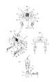
図3(a)〜(d)に示すのは本発明プロテクトサポータの一実施例であって、ロボットの左半身に装着するプロテクトサポータ一式である。右半身にはこれと対称に構成されたプロテクトサポータ一式を装着するものとする。図3(a)〜(d)はそれぞれ、上腕プロテクトサポータ21、肘下プロテクトサポータ22、手首プロテクトサポータ23、手先プロテクトサポータ24である。これらのプロテクトサポータは、それぞれ図6(a)〜(d)および図7(a)〜(c)に示すように装着され、上腕プロテクトサポータ21は肘関節11を、肘下プロテクトサポータ22は腕捻り関節7を、手首プロテクトサポータ23は手首関節12を、手先プロテクトサポータ24はエンドエフェクタとしての手5を保護する。
FIGS. 3A to 3D show an embodiment of the protect supporter according to the present invention, which is a set of protect supporters attached to the left half of the robot. It is assumed that a set of protect supporters that are configured symmetrically is attached to the right half of the body. 3A to 3D show an upper arm protect
このとき、各プロテクトサポータ21〜24は、例えばクロロプレンゴムなどの発泡ゴムである衝撃吸収部を、伸縮性を呈するシート状の表層部で覆ったものにより構成するものとする。この構成により、安価に衝撃吸収性能を備えたサボ一夕を構成することができる。また、プロテクトサポータの、衝撃吸収部をサンドイッチする表層部には、内側はすべりが悪く、外側はすべりが良い物を使用することで、ロボットに対するずれ幅を小さく抑えることができる。 At this time, each protect supporter 21-24 shall be comprised by what covered the impact-absorbing part which is foam rubbers, such as chloroprene rubber, with the sheet-like surface layer part which exhibits a stretching property, for example. With this configuration, it is possible to configure a sabo evening having shock absorbing performance at low cost. Further, the surface portion of the protect supporter sandwiching the shock absorbing portion is made of a material that does not slide on the inside and has a good surface on the outside, so that the displacement with respect to the robot can be kept small.
これらのプロテクトサポータ21〜24は、前述の生地に例えばマジックテープ(登録商標)などの面ファスナ25を縫製し、各関節に巻きつける構成とする。この構成により、プロテクトサポータは常に簡単に着脱可能となり、デザイン変更や経年劣化、汚染などに際して交換する際のコストを格段に低減することが可能となる。
These protect
また、人と接触しやすい部位に使用する衝撃吸収材には、例えばKINOTEX(登録商標)などの触覚センサを配置することで、人との接触を容易に検知することができる。接触を検知した際に作動モードを切り替えるようなシステムとすることも可能であり、より安全性を強化することができる。 In addition, for example, a touch sensor such as KINOTEX (registered trademark) is disposed on the shock absorbing material used in a portion that is easily in contact with a person, so that contact with the person can be easily detected. It is also possible to adopt a system that switches the operation mode when contact is detected, and the safety can be further enhanced.
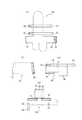
図4(a)〜(d)に示すのは本発明カバーの一実施例の正面図、斜視図、上面図、右側面図である。図5(a)〜(c)に示すのはその実施例のカバーの背面図、下面図、左側面図である。このカバー31は、現在流通している人間用の素材で、ロボットの可動範囲に柔軟にフィットし、耐久性を有する素材により構成する。収縮可能な素材(例えばポリウレタンなど)を使用する場合には、縫製する糸も収縮可能なものを使用する。こうすることで、耐久性を向上する。反対に、収縮可能でない生地(例えばポリエステルなど)を使用する場合は、各所にプリーツ加工を施し、可動範囲に対応する。特殊な素材を使わず、現在流通している人間用の素材を使用することで、人間の作業着と同様に洗濯が可能となり、汚染の激しい環境にあっても、常に清潔に保つことができる。
4A to 4D are a front view, a perspective view, a top view, and a right side view of an embodiment of the cover of the present invention. 5A to 5C are a rear view, a bottom view, and a left side view of the cover of the embodiment. The
また、ロボット体内でファンを使用したとき、カバー31がフィルタ機能を補うことができ、外部からの粉塵などがロボット体内に収集することを防ぐことができる。さらに、ファンの排気および吸気のための通気口8を覆う箇所は、本実施例においてはメッシュ素材を使用した通気部32で構成する。熱を逃がしやすくするためである。同時にデザイン性も兼ね備えることができる。また、作動モードに応じて点灯が切り替わるランプ部分15を覆う箇所もメッシュ素材32で構成する。可視性を保持するためである。
Further, when the fan is used in the robot body, the
カバー31のデザインは、いかようにもデザインすることができ、様々な工場やラインのデザインに合わせることができる。さらに、人間と同様に名札でロボットを管理することもできる。このような構成とすることで、本来ロボットが有する無機質なイメージを覆すことができる。それだけでなく、個体の識別性が格段に向上することで、ライン間およびライン内での個体管理も飛躍的に容易になる。
The design of the
また、カバー31が着脱容易であることから、ロボットの配置転換等により、外観を変えたい時にも迅速に対応可能である。手先36などの注意を集めたい部位は、目立つ色の生地を使用して、一層視認性を高めることができる。また、カバー31をクリーンエリア用に構成することで、ロボットは人間と同様に一般作業エリアからクリーンエリアに入ることができる。
In addition, since the
図8(a)〜(d)、および図9の(a)〜(c)に示すのは、図3および図4に示すロボット用カバーを図1および図2に示す双腕ロボットに装着した状態である。このとき、双腕ロボットの運転中、ロボット用カバー31が双腕ロボットに対してずれないように、双腕ロボットの肩に対応する部分に、図示しない、例えば面ファスナなどのファスナを取り付け、留めることができる構成とする。また、腰軸の旋回時にカバーが引っかからないように、紐33でカバーの腰を絞ることができる構成とする。
FIGS. 8A to 8D and 9A to 9C show that the robot cover shown in FIGS. 3 and 4 is attached to the double-arm robot shown in FIGS. State. At this time, during operation of the double-arm robot, a fastener such as a hook-and-loop fastener (not shown) is attached and fastened to a portion corresponding to the shoulder of the double-arm robot so that the
このカバー31にはさらに、図10に示すように、背中の中央右側にジッパ37を設け、作業者がロボットに容易にアクセスできるようにする。また、左右の手先36にもそれぞれジッパ38を設け、手5などのエンドエフェクタが取り付けてある状態でも容易に袖を過すことができるようにする。
As shown in FIG. 10, the
以上図と共に述べた実施例は、あくまでも本発明の実施形態の例示であり、当業者は本発明の請求の範囲内で様々な変更を考え得るだろう。例えば、カバーの形態は浴衣やワイシャツのような前開きのものとしても良く、また、カバー全体をメッシュ素材としても良い。また、本発明のロボット用サポートプロテクタおよびカバーは、双方を同時に装着すると特に好適であるが、どちらか一方のみを使用する場合にも請求項の範囲に含まれる形態において充分課題を達成し得るだろう。 The examples described above with the drawings are merely examples of the embodiments of the present invention, and those skilled in the art will be able to consider various modifications within the scope of the claims of the present invention. For example, the form of the cover may be a front opening type such as a yukata or a shirt, and the entire cover may be a mesh material. In addition, the robot support protector and the cover of the present invention are particularly preferably mounted at the same time, but even when only one of them is used, the problems within the scope of the claims can be sufficiently achieved. Let's go.
かくして本発明のサポートプロテクタおよびロボット用カバーによれば、人間と協働するためにデザインされたロボットにおいて、その外皮構造を軽量かつ安価に構成することができ、また、同時に高い安全性と取替え容易性、さらに優れた固体識別性および意匠性を呈することができる。 Thus, according to the support protector and the robot cover of the present invention, the outer skin structure of the robot designed for cooperating with humans can be configured at a light weight and at a low cost, and at the same time, high safety and easy replacement. Properties, and excellent solid identification and design properties.
1 双腕ロボット
2 胴体
3 頭
4 腕
4a 上腕
4b 下腕
5 手
7 腕捻り関節
8 通気口
10 肩関節
11 肘関節
12 手首関節
15 ランプ部分
21 上腕プロテクトサポータ
22 肘下プロテクトサポータ
23 手首プロテクトサポータ
24 手先プロテクトサポータ
31 カバー
32 通気部
33 紐
36 手先
37 ジッパ
38 ジッパ
DESCRIPTION OF SYMBOLS 1 Dual arm robot 2 Body 3
Claims (2)
Priority Applications (1)
| Application Number | Priority Date | Filing Date | Title |
|---|---|---|---|
| JP2008301513A JP4781420B2 (en) | 2008-11-26 | 2008-11-26 | Protect supporter for robot |
Applications Claiming Priority (1)
| Application Number | Priority Date | Filing Date | Title |
|---|---|---|---|
| JP2008301513A JP4781420B2 (en) | 2008-11-26 | 2008-11-26 | Protect supporter for robot |
Publications (2)
| Publication Number | Publication Date |
|---|---|
| JP2010125546A JP2010125546A (en) | 2010-06-10 |
| JP4781420B2 true JP4781420B2 (en) | 2011-09-28 |
Family
ID=42326283
Family Applications (1)
| Application Number | Title | Priority Date | Filing Date |
|---|---|---|---|
| JP2008301513A Active JP4781420B2 (en) | 2008-11-26 | 2008-11-26 | Protect supporter for robot |
Country Status (1)
| Country | Link |
|---|---|
| JP (1) | JP4781420B2 (en) |
Cited By (2)
| Publication number | Priority date | Publication date | Assignee | Title |
|---|---|---|---|---|
| US10913251B2 (en) | 2015-09-01 | 2021-02-09 | Mitsui Chemicals, Inc. | Buffer material, buffer material for coating robot, robot with buffer material, and coating robot with buffer material |
| EP3978207A4 (en) * | 2020-07-08 | 2022-08-31 | CloudMinds Robotics Co., Ltd. | Robot and housing thereof |
Families Citing this family (14)
| Publication number | Priority date | Publication date | Assignee | Title |
|---|---|---|---|---|
| CN104870147B (en) * | 2012-08-31 | 2016-09-14 | 睿信科机器人有限公司 | The system and method for robot security's work |
| JP5902664B2 (en) | 2013-12-25 | 2016-04-13 | ファナック株式会社 | Human cooperative industrial robot with protective member |
| FR3020847B1 (en) * | 2014-05-07 | 2017-01-13 | Aldebaran Robotics | SHOCK ABSORBER DEVICE FOR A HUMANOID ROBOT |
| CN109070364B (en) * | 2016-05-12 | 2022-05-13 | Groove X 株式会社 | Action-independent robot with emergency shutdown function |
| JP6444942B2 (en) | 2016-05-26 | 2018-12-26 | ファナック株式会社 | Robot with a tool having a shock absorbing member |
| JP6794800B2 (en) | 2016-11-29 | 2020-12-02 | セイコーエプソン株式会社 | robot |
| JP6407945B2 (en) * | 2016-12-06 | 2018-10-17 | ファナック株式会社 | Robot's conductive path structure |
| JP7098312B2 (en) * | 2017-02-03 | 2022-07-11 | ソニー・オリンパスメディカルソリューションズ株式会社 | Protective cover and medical observation device |
| JP7045170B2 (en) * | 2017-11-24 | 2022-03-31 | 川崎重工業株式会社 | robot |
| JP6936713B2 (en) * | 2017-11-27 | 2021-09-22 | 株式会社デンソーウェーブ | Protective jacket for robots |
| JP7355589B2 (en) * | 2018-10-16 | 2023-10-03 | Thk株式会社 | humanoid robot |
| WO2020080366A1 (en) * | 2018-10-16 | 2020-04-23 | 美津濃株式会社 | Garment |
| WO2020080330A1 (en) * | 2018-10-16 | 2020-04-23 | Thk株式会社 | Humanoid robot |
| CN111759659B (en) * | 2020-05-18 | 2022-07-19 | 力之医疗科技(广州)有限公司 | Portable wearable upper limb rehabilitation robot |
Family Cites Families (5)
| Publication number | Priority date | Publication date | Assignee | Title |
|---|---|---|---|---|
| JP2001239479A (en) * | 1999-12-24 | 2001-09-04 | Sony Corp | Leg type mobile robot and exterior module for robot |
| JP2003001582A (en) * | 2001-06-21 | 2003-01-08 | Kenji Fuse | Costume for robot |
| JP3706113B2 (en) * | 2003-03-24 | 2005-10-12 | 株式会社国際電気通信基礎技術研究所 | Communication robot |
| JP2005161437A (en) * | 2003-12-01 | 2005-06-23 | Kawada Kogyo Kk | Hip structure of anthropomorphic robot |
| JP2005199385A (en) * | 2004-01-15 | 2005-07-28 | Yaskawa Electric Corp | Robot |
-
2008
- 2008-11-26 JP JP2008301513A patent/JP4781420B2/en active Active
Cited By (2)
| Publication number | Priority date | Publication date | Assignee | Title |
|---|---|---|---|---|
| US10913251B2 (en) | 2015-09-01 | 2021-02-09 | Mitsui Chemicals, Inc. | Buffer material, buffer material for coating robot, robot with buffer material, and coating robot with buffer material |
| EP3978207A4 (en) * | 2020-07-08 | 2022-08-31 | CloudMinds Robotics Co., Ltd. | Robot and housing thereof |
Also Published As
| Publication number | Publication date |
|---|---|
| JP2010125546A (en) | 2010-06-10 |
Similar Documents
| Publication | Publication Date | Title |
|---|---|---|
| JP4781420B2 (en) | Protect supporter for robot | |
| JP6776340B2 (en) | Outerwear with hidden stretchable back layer | |
| CN102987590B (en) | Cycling outer shell | |
| JP6908910B2 (en) | Garment and cooling system | |
| JP6446734B1 (en) | Protective clothing and method of manufacturing protective clothing | |
| WO2015008529A1 (en) | Device for ventilating inside of helmet | |
| KR100763720B1 (en) | A face protector for working | |
| JP7209527B2 (en) | protective clothing for robots | |
| JP2021508608A (en) | Safety protection of robot joints | |
| JP2525267B2 (en) | Ceiling-mounted manipulator arm cover | |
| US20190116905A1 (en) | Convertible headwear | |
| JP2004183157A (en) | Protection wear for humanoid robot | |
| JP5183607B2 (en) | clothes | |
| JP3612085B2 (en) | Master arm device for master / slave system | |
| JP2019052414A (en) | Rain pants | |
| KR102068045B1 (en) | Protective clothing with pleats | |
| US7308720B1 (en) | Multi-positionable headwear system | |
| JP3218270U (en) | Rain kappa | |
| JP2017160573A (en) | Protective hood | |
| WO2020080330A1 (en) | Humanoid robot | |
| JP4365195B2 (en) | Multiple movable axis drive cover for humanoid robot | |
| JP2007138330A (en) | Rain coat | |
| CN212994522U (en) | Sun-proof breathable garment | |
| JP5918819B2 (en) | Hood and method of manufacturing the hood | |
| JP2020016001A (en) | Working jacket |
Legal Events
| Date | Code | Title | Description |
|---|---|---|---|
| A977 | Report on retrieval |
Free format text: JAPANESE INTERMEDIATE CODE: A971007 Effective date: 20101115 |
|
| A131 | Notification of reasons for refusal |
Free format text: JAPANESE INTERMEDIATE CODE: A131 Effective date: 20110405 |
|
| A521 | Request for written amendment filed |
Free format text: JAPANESE INTERMEDIATE CODE: A523 Effective date: 20110530 |
|
| TRDD | Decision of grant or rejection written | ||
| A01 | Written decision to grant a patent or to grant a registration (utility model) |
Free format text: JAPANESE INTERMEDIATE CODE: A01 Effective date: 20110614 |
|
| A01 | Written decision to grant a patent or to grant a registration (utility model) |
Free format text: JAPANESE INTERMEDIATE CODE: A01 |
|
| A61 | First payment of annual fees (during grant procedure) |
Free format text: JAPANESE INTERMEDIATE CODE: A61 Effective date: 20110705 |
|
| FPAY | Renewal fee payment (event date is renewal date of database) |
Free format text: PAYMENT UNTIL: 20140715 Year of fee payment: 3 |
|
| R150 | Certificate of patent or registration of utility model |
Free format text: JAPANESE INTERMEDIATE CODE: R150 Ref document number: 4781420 Country of ref document: JP Free format text: JAPANESE INTERMEDIATE CODE: R150 |
|
| R250 | Receipt of annual fees |
Free format text: JAPANESE INTERMEDIATE CODE: R250 |
|
| R250 | Receipt of annual fees |
Free format text: JAPANESE INTERMEDIATE CODE: R250 |
|
| R250 | Receipt of annual fees |
Free format text: JAPANESE INTERMEDIATE CODE: R250 |
|
| R250 | Receipt of annual fees |
Free format text: JAPANESE INTERMEDIATE CODE: R250 |
|
| R250 | Receipt of annual fees |
Free format text: JAPANESE INTERMEDIATE CODE: R250 |
|
| R250 | Receipt of annual fees |
Free format text: JAPANESE INTERMEDIATE CODE: R250 |
|
| R250 | Receipt of annual fees |
Free format text: JAPANESE INTERMEDIATE CODE: R250 |
|
| R250 | Receipt of annual fees |
Free format text: JAPANESE INTERMEDIATE CODE: R250 |
|
| R250 | Receipt of annual fees |
Free format text: JAPANESE INTERMEDIATE CODE: R250 |
|
| R250 | Receipt of annual fees |
Free format text: JAPANESE INTERMEDIATE CODE: R250 |