JP4779986B2 - Wireless tag reader - Google Patents
Wireless tag reader Download PDFInfo
- Publication number
- JP4779986B2 JP4779986B2 JP2007027951A JP2007027951A JP4779986B2 JP 4779986 B2 JP4779986 B2 JP 4779986B2 JP 2007027951 A JP2007027951 A JP 2007027951A JP 2007027951 A JP2007027951 A JP 2007027951A JP 4779986 B2 JP4779986 B2 JP 4779986B2
- Authority
- JP
- Japan
- Prior art keywords
- correlation value
- data
- waveform
- threshold
- value
- Prior art date
- Legal status (The legal status is an assumption and is not a legal conclusion. Google has not performed a legal analysis and makes no representation as to the accuracy of the status listed.)
- Expired - Fee Related
Links
- 238000001514 detection method Methods 0.000 claims description 21
- 238000005070 sampling Methods 0.000 claims description 18
- 230000003247 decreasing effect Effects 0.000 claims description 4
- 238000004904 shortening Methods 0.000 claims 1
- 238000000034 method Methods 0.000 description 13
- 230000007423 decrease Effects 0.000 description 12
- 238000004891 communication Methods 0.000 description 9
- 230000000875 corresponding effect Effects 0.000 description 9
- 238000006243 chemical reaction Methods 0.000 description 7
- 238000010586 diagram Methods 0.000 description 4
- 230000003111 delayed effect Effects 0.000 description 3
- 230000005540 biological transmission Effects 0.000 description 2
- 230000000694 effects Effects 0.000 description 2
- 230000015572 biosynthetic process Effects 0.000 description 1
- 230000002596 correlated effect Effects 0.000 description 1
- 238000012986 modification Methods 0.000 description 1
- 230000004048 modification Effects 0.000 description 1
- 238000003786 synthesis reaction Methods 0.000 description 1
Images


Description
本発明は、無線タグと非接触通信を行う無線タグリーダに関する。 The present invention relates to a wireless tag reader that performs non-contact communication with a wireless tag.
無線タグと無線タグリーダとの間で行う通信の方式は複数存在するが、それらは規格化されており、例えば、(1)ISO/IEC18000-6タイプB,(2)EPC Global Class1,(3)EPC Global Class1 Generation2などがある。(1)では、無線タグからタグリーダに送信されるデータにFM0符号化を使用しており、(2)では、同データにF2F符号化を使用している。また、(3)では、同データにFM0符号化,又はミラーサブキャリア符号化を使用している。 There are several methods of communication between wireless tags and wireless tag readers, but they are standardized, for example, (1) ISO / IEC18000-6 type B, (2) EPC Global Class1, (3) EPC Global Class1 Generation2 etc. In (1), FM0 encoding is used for data transmitted from the wireless tag to the tag reader, and in (2), F2F encoding is used for the data. In (3), FM0 encoding or mirror subcarrier encoding is used for the same data.
そして、タグリーダが上記の各方式に夫々対応するには、異なる構成の復調回路を備える必要があり、回路の構成や規模が複雑になるという問題があった。
尚、上記の先行技術に対応する無線タグリーダは周知のものに他ならず、技術的特徴は存在しないため、対応する技術文献を提示する必要は無いと考える。
本発明は上記事情に鑑みてなされたものであり、その目的は、無線タグが採用する通信方式が異なる場合でも、共通の復調回路で対応することができる無線タグリーダを提供することにある。
In order for the tag reader to correspond to each of the above-described methods, it is necessary to provide a demodulator circuit having a different configuration, resulting in a problem that the circuit configuration and scale are complicated.
Note that the wireless tag reader corresponding to the above-described prior art is nothing but a known one, and there is no technical feature, so that it is not necessary to present the corresponding technical literature.
The present invention has been made in view of the above circumstances, and an object of the present invention is to provide a wireless tag reader that can cope with a common demodulation circuit even when the communication method adopted by the wireless tag is different.
請求項1記載の無線タグリーダによれば、相関値算出手段が、受信データ波形のサンプリング値と基準データとの相関値を算出すると、閾値算出手段は、相関値についてデータビットを復号するための閾値を算出する。具体的には、受信信号の振幅値を絶対値加算して平均値を算出すると、その平均値より得られる最大の相関値に基づいて正側閾値を算出し、その正側閾値の符号を反転させたものを負側閾値として設定し、データ復号手段は、相関値と閾値とに基づいてデータビットを復号する。
According to the wireless tag reader of
即ち、無線タグが採用する通信方式が異なる場合でも、データ「1,0」の符号化方式は、基本的にデータ波形を2値レベルの間でどのように変化させるかによっている。従って、そのデータ波形と所定の基準データとの相関値を得れば、符号化データと基準データとの一致度合い,換言すれば、前者が後者を基準としてどのように変化しているのかが示される。そして、受信信号振幅の平均値より得られる最大の相関値より正側閾値,並びに負側閾値を算出し、相関値と閾値とを比較してデータ波形の変化を捉えれば、無線タグについて使用されている範囲内で符号化方式が異なるデータを復号することが可能となる。 That is, even when the communication method employed by the wireless tag is different, the encoding method of the data “1, 0” basically depends on how the data waveform is changed between binary levels. Therefore, if the correlation value between the data waveform and the predetermined reference data is obtained, the degree of coincidence between the encoded data and the reference data, in other words, how the former changes with respect to the latter is shown. It is. Then, the positive threshold value and the negative threshold value are calculated from the maximum correlation value obtained from the average value of the received signal amplitude, and the correlation value is compared with the threshold value to capture the change in the data waveform. Thus, it is possible to decode data with different encoding methods within the range.
ここで、受信データのビットレートが変動することで、1ビットのデータを示す期間(周期)が、周期の中央で位相が180度変化する波形の基準データについて設定されている1ビットの期間よりも短くなると、両者の期間差に応じて、相関値算出手段が算出する相関値のピークが一時的に低下する。すると、そのピークが閾値算出手段によって算出された閾値にかからなくなり、誤判定が生じる可能性がある。
そこで、基準データを、受信信号について許容されている変動の下限周期を下回る周期に設定しておけば、受信データのビットレートが変動しても受信データと基準データとの波形が一致し易くなって相関値のピークが低下することを防止できるので、誤判定が生じるのを回避することが可能となる。
Here, when the bit rate of the received data fluctuates, the period (cycle) indicating 1-bit data is longer than the 1-bit period set for the reference data having a waveform whose phase changes by 180 degrees at the center of the period. If it becomes shorter, the peak of the correlation value calculated by the correlation value calculation means temporarily decreases according to the difference between the two periods. Then, the peak does not fall on the threshold value calculated by the threshold value calculation means, and erroneous determination may occur.
Therefore, if the reference data is set to a cycle that is less than the lower limit cycle of the variation allowed for the received signal, the waveform of the received data and the reference data can be easily matched even if the bit rate of the received data varies. Thus, it is possible to prevent the correlation value peak from being lowered, so that it is possible to avoid erroneous determination.
請求項2記載の無線タグリーダによれば、基準データを、波形のレベルが同一極性を示す期間で一定であり、且つ前記レベルの絶対値が等しくなるように設定するので、2値レベル間で変換する受信データ波形との相関を適切に得ることができる。
According to the wireless tag reader of
請求項3記載の無線タグリーダによれば、無線タグについて使用されている範囲内で符号化方式が異なるデータを復号できる効果については、請求項1と同様であるが、基準データについては、波形の周期中央で位相が180度変化すると共に、中央におけるレベルが最大に設定され、且つ同一極性を示す期間内でレベルが1段階以上変化する波形としている。すると、上記のように受信データのビットレートが変動した場合には、基準データ波形の始期側,終期側のレベルが中央の最大レベルよりも低くなっているので、受信データとの期間にずれが生じた場合に、相関値のピークレベルが低下する度合いが小さくなる。従って、受信データの誤判定を防止することができる。
According to the wireless tag reader of
請求項4記載の無線タグリーダによれば、無線タグについて使用されている範囲内で符号化方式が異なるデータを復号できる効果については、請求項1,3と同様であり、波形周期変化手段は、相関値がピークを示す位置を検出してその検出間隔を求め、最新の検出間隔が前回よりも増加した場合は基準データの波形周期を延長し、最新の検出間隔が前回よりも減少した場合は基準データの波形周期を短縮する。即ち、受信データのビットレートが変動するのに応じて、基準データの波形周期をダイナミックに変化させるので、受信データの通信レート変動が、どのような範囲で生じるのかが事前に把握できない場合であっても、その変動に追従して相関値のピークレベルが低下することを防止できる。
According to the wireless tag reader of
請求項5記載の無線タグリーダによれば、波形周期変化手段は、基準データの波形周期を、最新の検出間隔よりも常に短くなるように変化させるので、請求項1と同様の効果により、受信データのビットレートが変動した場合でも相関値のピークが低下することを防止できる。また、ビットレートの変動に追従して基準データの波形周期を変化させる制御を簡単に行うことができる。
According to the wireless tag reader of
(第1実施例)
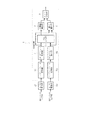
以下、本発明の一実施例について図面を参照して説明する。図1は、無線タグリーダの構成を、本発明の要旨にかかる部分を中心に示す機能ブロック図である。無線タグリーダ1は、無線タグからの応答信号を受信すると、RF部(何れも図示せず)において、位相が互いに90度異なる搬送波を用いて復調し、2系列のベースバンド信号であるI信号,Q信号を出力する。そして、A/D変換部2I,2Qは、I信号,Q信号を夫々A/D変換すると、サンプリングレート変換部(サンプリングレート設定手段)3I,3Qに出力する。
(First embodiment)
An embodiment of the present invention will be described below with reference to the drawings. FIG. 1 is a functional block diagram showing a configuration of a wireless tag reader with a focus on a portion according to the gist of the present invention. When receiving a response signal from the wireless tag, the
サンプリングレート変換部3I,3Qは、A/D変換部2I,2QによってA/D変換されたデータを間引きしてサンプリングレートを低下させるように変換すると、各データをDCオフセット除去部4I,4Qに出力する。DCオフセット除去部4I,4Qは、入力データに含まれているDCオフセット分を除去した後、データをIQ合成部5,並びに閾値算出部(閾値算出手段)6に出力する。尚、図2には、DCオフセット除去部4I,4Qより出力されるI信号,Q信号のデータイメージ(I1〜I8,Q1〜Q8)を示す。また、最初にA/D変換部2I,2Qにおいて、後のデータ処理で使用されるサンプリングレートよりも高いレートでA/D変換を行なっているのは、タグ側のデータ送信速度が異なる場合でも十分に対応するためである。
When the sampling
IQ合成部5は、I側及びQ側のデータについて、振幅レベルの変化を拡張するように重み付け処理し、Q側のデータの位相をI側の位相に合わせて加算することで両者を合成する。そして、合成したデータを相関値算出部(相関値算出手段)7に出力する。
The
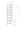
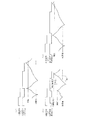
図3(a)は、相関値算出部7Xの内部構成を示すものである。ここでは、先ず基本原理を説明するため、受信データの1ビット当たりのサンプリング数と、基準データ波形のサンプル数とを同じにした相関値算出部7Xの構成を示す。相関値算出部7Xは、7次のマッチドフィルタとして構成されており、その次数は、図2に示すように、I,Q信号のデータ波形の最小変化周期におけるサンプル数「8」より「1」を減じた数に対応している。相関値算出部7Xは、直列に接続された7つの遅延器11と、8つの乗算器12と、7つの加算器13とで構成されている。
FIG. 3A shows the internal configuration of the correlation
乗算器12(1)〜12(4)は、遅延器11(1)〜(4)の各入力側の信号に係数「+1」を乗じ、乗算器12(5)〜12(8)は、遅延器11(5)〜(7)の各入力側信号,及び遅延器11(7)の出力側信号に係数「−1」を乗じるようになっている。そして、初段の加算器13(1)は、乗算器12(1),12(2)の出力を加算し、加算器13(2)は、乗算器12(3),加算器13(1)の出力を加算する。以降、加算器13(3)〜13(7)は、加算対象とする乗算器12,加算器13を順次シフトさせ、最終段の加算器13(7)の出力が、相関値として図1に示すビット復号部(データ復号手段)8に出力される。
また、図3(b)には、8つの乗算器12の係数が示すデータ値を時系列に並べることで表される基準データ波形を示しており、結果として、相関値算出部7Xは、入力信号と図3(b)に示す基準データとの相関値を出力することになる。
The multipliers 12 (1) to 12 (4) multiply the signals on the input sides of the delay units 11 (1) to (4) by a coefficient “+1”, and the multipliers 12 (5) to 12 (8) Each input side signal of the delay units 11 (5) to (7) and the output side signal of the delay unit 11 (7) are multiplied by a coefficient “−1”. The first stage adder 13 (1) adds the outputs of the multipliers 12 (1) and 12 (2), and the adder 13 (2) is the multiplier 12 (3) and the adder 13 (1). Add the outputs of. Thereafter, the adders 13 (3) to 13 (7) sequentially shift the
FIG. 3B shows a reference data waveform represented by arranging the data values indicated by the coefficients of the eight
また、図4は、閾値算出部6の内部構成を示すものである。I側平均算出部14I,Q側平均算出部14Qは、I信号,Q信号の夫々について振幅を絶対値加算して平均値を算出し、乗算器15I,15Qに夫々出力する。乗算器15I,15Qは、夫々の平均値を2乗することで平均値の振幅変化に重み付けをして加算器16に出力し、加算器16は加算結果を乗算器17に出力する。乗算器17は、上記加算結果に、相関値算出部7Xによって得られる相関値の最大値「+8」を乗じると、次段の乗算器18に出力する。ここで、I信号とQ信号の平均値を合成しているのは、受信信号の振幅変化をより明瞭に捉えるためである。
FIG. 4 shows the internal configuration of the threshold
乗算器18は、乗算器17の乗算結果に所定の比率rを乗じたものを、相関値の正側閾値としてビット復号器8に出力する。尚、上記の比率は、閾値が大きくなり過ぎないように抑制するため乗じられる。そして、上記正側閾値に、乗算器19が「−1」を乗じて符号を反転させたものが負側閾値として出力される。
The
次に、上記構成の作用について図5乃至図8も参照して説明する。
<ISO/IEC18000-6タイプB>
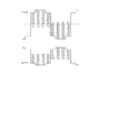
図5は、ISO/IEC18000-6タイプBに対応するFM0符号化の場合であり、(a)は無線タグが送信するプリアンブルの波形を示しており、「×××00000001××11×」となっている。尚、「×」は、データ「1」,「0」の何れでもない波形である。また、(b)のデータ波形は、1データビット期間の中央で位相変化(エッジ)があればデータ「0」,位相変化が無ければデータ「1」が割り当てられている。
Next, the operation of the above configuration will be described with reference to FIGS.
<ISO / IEC18000-6 Type B>
FIG. 5 shows a case of FM0 encoding corresponding to ISO / IEC18000-6 type B. FIG. 5A shows a waveform of a preamble transmitted by the wireless tag, which is “xxx00000001xxx11x”. It has become. Note that “x” is a waveform that is neither data “1” nor “0”. The data waveform of (b) is assigned data “0” if there is a phase change (edge) in the center of one data bit period, and data “1” if there is no phase change.
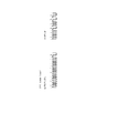
図6は、ISO/IEC18000-6タイプBに対応するFM0符号化データをタグリーダ1が受信し、ビット復号部8において(a)プリアンブルを検出する場合と、(b)データを復号する場合との判定処理を示すタイミングチャートである。図6(a)に示すように、入力信号の波形変化に応じて、相関値検出部7より出力される相関値はサンプリングタイミング毎に変化する。そして、プリアンブルを検出する場合は、相関値と正側,負側閾値とを比較判定するタイミングを、1データビット期間の初めと終わりより若干遅れた時点と、それらの中間とに設定する。
FIG. 6 shows a case where the
プリアンブル中のデータ「0」に対応する波形は、実際には振幅がアナログ的に変化しているが、便宜的に振幅が「±1」間で変化する矩形波として示すと、1データビット期間の前半が「−1」を,後半は「+1」を示すので、何れも基準データとの相関が低くなっている。そのため、相関値は期間前半で順次減少し、後半で順次上昇するように変化し、その振幅の最大値は「±8」となっている。そして、データ「0」が連続している間は同一の変化パターンを繰り返す。
閾値算出部6によって得られる閾値は、相関値の正,負のピークを若干下回るように、比率rによって調整されている。但し、図中の閾値は常に一定のように示しているが、実際には、データ値の変化に応じて変動する。
The waveform corresponding to the data “0” in the preamble actually changes in amplitude in an analog manner, but for convenience, it is represented as a rectangular wave whose amplitude changes between “± 1”. Since the first half indicates “−1” and the second half indicates “+1”, the correlation with the reference data is low. Therefore, the correlation value gradually decreases in the first half of the period and gradually increases in the second half, and the maximum value of the amplitude is “± 8”. The same change pattern is repeated while data “0” continues.
The threshold value obtained by the threshold
そして、各判定タイミングにおいて、相関値が正側閾値を超えると「H」,負側閾値を下回ると「L」,何れでもない場合は「0」を割り当てると、データ「0」が連続している間の判定パターンは「LHLH…」を繰り返すことになる。その状態から最初のデータ「1」が現れると、判定パターンが変化する。即ち、「01××11×」に応じて、判定パターンは「LHL00H0LH0L00HL」となるので、上記の判定パターンを捉えてプリアンブルを検出する。 At each determination timing, when the correlation value exceeds the positive threshold, “H” is assigned, and when the correlation value falls below the negative threshold, “L” is assigned. The determination pattern while “LHLH... When the first data “1” appears from this state, the determination pattern changes. That is, since the determination pattern is “LHL00H0LH0L00HL” in accordance with “01xxx × 11 ×”, the preamble is detected by capturing the above determination pattern.
また、図6(b)に示すように、データの復号については、1データビット期間の中央より僅かに遅れたタイミングで判定を行うようになっており、判定周期はプリアンブル検出の場合の2倍(データ変化の最小周期)に設定されている。判定結果が「HH」又は「LL」の場合は論理「0」,判定結果が「HL」又は「LH」の場合は論理「1」としてNRZ(No Return to Zero)符号に変換することでデータビットを復号する。 Also, as shown in FIG. 6B, the data decoding is performed at a timing slightly delayed from the center of one data bit period, and the determination cycle is twice that in the case of preamble detection. (Minimum cycle of data change). When the determination result is “HH” or “LL”, the data is converted into an NRZ (No Return to Zero) code as logic “0”, and when the determination result is “HL” or “LH”, the data is converted into an NRZ (No Return to Zero) code. Decrypt the bit.
<EPC Global Class1>
図7は、EPC Global Class1に対応するF2F符号化の場合であり、データ「1」は、データ「0」に対して信号変化の周波数が2倍となる符号化形式である。(a)はプリアンブルパターンで「11111110」となっており、(b)は任意のデータである。
図8は、図6相当図である。F2F符号化の場合、データ「1」の最小変化周期について8個のサンプリングデータを得るようにする。図8(a)のプリアンブル検出では、データ「1」が相関値算出部7Xにおける基準データに一致する変化を示すので、相関値は、上記変化周期の前半で上昇,後半で下降するパターン(判定パターンは「HLHL…」)を繰り返す。
<EPC Global Class1>
FIG. 7 shows the case of F2F encoding corresponding to EPC Global Class1, and data “1” is an encoding format in which the frequency of signal change is doubled with respect to data “0”. (A) is a preamble pattern “11111110”, and (b) is arbitrary data.
FIG. 8 corresponds to FIG. In the case of F2F encoding, eight sampling data are obtained for the minimum change period of data “1”. In the preamble detection of FIG. 8A, since the data “1” indicates a change that matches the reference data in the correlation
そして、データ「1」の次にデータ「0」が現れると、データ「0」における第1最小変化周期の後半では基準データとの相関が低くなるため、相関値の下降度合いが緩やかになり判定パターンが変化する。続く第2周期の前半も相関は低いため相関値はそのまま下降し、後半は相関が高くなり上昇に転ずる。従って、判定パターンが「HLHLH0L0H」になった場合にプリアンブルを検出する。
図8(b)におけるデータ復号では、図6(b)のケースと同様にデータ変化の最小周期に判定を行うが、判定結果が「HHH」又は「LLL」の場合は論理「1」,判定結果が「HLH」又は「LHL」の場合は論理「0」としてNRZ符号に変換し、データビットを復号する。
When data “0” appears next to data “1”, the correlation with the reference data becomes low in the second half of the first minimum change period in data “0”, so that the degree of decrease in the correlation value becomes gradual and determination is made. The pattern changes. Since the correlation is low in the first half of the subsequent second period, the correlation value falls as it is, and in the second half, the correlation becomes high and starts to rise. Therefore, the preamble is detected when the determination pattern becomes “HLHLH0L0H”.
In the data decoding in FIG. 8B, the determination is made in the minimum cycle of the data change as in the case of FIG. 6B. If the determination result is “HHH” or “LLL”, the logical “1” is determined. When the result is “HLH” or “LHL”, it is converted into an NRZ code as logic “0”, and the data bits are decoded.
その他、EPC Global Class1 Generation2:FM0/ミラーサブキャリアの場合も、同様にしてデータを復号化することができるが、その詳細については、特願2006−342839号に記載されている。
In addition, in the case of EPC
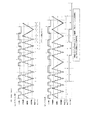
次に、相関値算出部7Xを用いた場合の問題点について、図9を参照して説明する。図9は、基準データ波形(比較波形)の周期に対して、受信データ波形の周期が変動する場合の相関値の変化を示すものである。尚、受信データ波形のレベル変化パターンは、基準データと同じである。(a)は、図5乃至図8で説明したように、両者の周期が一致する場合であり、(b)は、基準データ波形周期よりも受信データ波形周期が短くなった場合である。このケースでは、基準データ波形周期の始期,終期において両者のレベルが異なる期間が生じるため、その影響によって相関値のピークレベルが一時的に低下する。
Next, problems when the correlation
すると、その低下したピークレベルと周期が一致した場合に発生するピークレベルとの差が大きくなるため、高いピークに合わせて閾値を設定すると、ピークが低い場合は閾値に達しないケースが発生する。また、低いピークに合わせて閾値を設定すると、ピークが高い場合は閾値を超えるタイミングが早くなってしまう。その結果、データの復号に誤判定が生じるおそれがある。 Then, since the difference between the lowered peak level and the peak level generated when the period coincides becomes large, when the threshold is set in accordance with the high peak, there is a case where the threshold is not reached when the peak is low. In addition, when the threshold value is set in accordance with the low peak, when the peak is high, the timing of exceeding the threshold value is advanced. As a result, there is a risk of erroneous determination in data decoding.
図9(c)は、基準データ波形周期よりも受信データ波形周期が長くなった場合であるが、このケースでは、受信データ波形周期が長くなるのに応じてピークレベルが閾値を超えるタイミングが遅れるだけで、ピークレベルの変動は生じない。そして、相関値が閾値を超えたか否かを判定するタイミングについては、タグリーダ側で随時修正して追従させることができるため、問題とはならない。 FIG. 9C shows a case where the received data waveform period becomes longer than the reference data waveform period. In this case, the timing at which the peak level exceeds the threshold is delayed as the received data waveform period becomes longer. As a result, the peak level does not change. The timing for determining whether or not the correlation value exceeds the threshold value can be corrected at any time on the tag reader side so that it does not matter.
図10は、上記の問題を解決するように構成された相関値算出部7を示すものである。この相関値算出部7は、図3に示した相関値算出部7Xより、初段の遅延器11(1),乗算器12(1),加算器13(1)を削除すると共に、最終段の遅延器11(7),乗算器12(8),加算器13(7)を削除した構成となっている。即ち、図11に示すように、(a)受信データの1ビット当たりのサンプリング数「8」に対して、マッチドフィルタの次数が「5」、(b)基準データ波形の周期としてはサンプル数「6」,−25%となるように設定されている。
これは、無線タグより返信される応答信号について、1ビットデータの送信期間の変動が通信仕様上±20%の範囲で許容されていることを前提として、その変動の下限である−20%よりも基準データ波形の周期が短くなるように設定したものである。
FIG. 10 shows a correlation
This is because the response signal returned from the wireless tag is based on the assumption that the variation of the transmission period of 1-bit data is allowed in the range of ± 20% in the communication specification, from −20% which is the lower limit of the variation. Is set so that the cycle of the reference data waveform is shortened.
上記構成の相関値算出部7を用いた場合の作用を、図12及び図13を参照して説明する。これらの図は、基準データ波形周期と受信データ波形周期との関係を適宜設定した場合に、相関値算出部より得られる相関値をシミュレーションしたものである。図12(a)は、基準データ波形周期を8サンプル(Typ周期)とする相関値算出部7Xを用いて、受信データ波形の周期が下限(Min)まで変動するケースが発生した場合であり、相関値の負側のピークレベルが変動している。
The operation when the correlation
そして、図12(b)は、(a)と同じ受信データ波形について、相関値算出部7を適用した場合であり、(a)のようなピークレベルの変動は発生せず同じレベルとなっていることが判る。即ち、受信データ波形の周期は基準データ波形周期よりも常に長くなることから、両者の波形がより一致し易くなる結果、相関値のピークが低下しなくなっている。
FIG. 12B shows a case where the correlation
また、図13(a)は、相関値算出部7に対して、受信データ波形の周期が標準値で一定となる場合であり、やはりピークレベルの変動は発生していない。そして、図13(b)は、相関値算出部7に対して、受信データ波形の周期が上限(Max)まで変動する場合であり、この場合もピークレベルの変動は発生しない。
FIG. 13A shows a case where the period of the received data waveform is constant at the standard value with respect to the correlation
以上のように本実施例によれば、無線タグリーダ1において、相関値算出部7が、受信データ波形のサンプリング値と基準データとの相関値を算出すると、閾値算出部6は、相関値についてデータビットを復号するための閾値を算出する。具体的には、受信信号の振幅値を絶対値加算して平均値を算出すると、その平均値より得られる最大の相関値に基づいて正側閾値を算出し、その正側閾値の符号を反転させたものを負側閾値として設定し、データ復号手段は、相関値と閾値とに基づいてデータビットを復号する。
As described above, according to the present embodiment, in the
即ち、無線タグが採用する通信方式が異なる場合でも、データ「1,0」の符号化方式は、基本的にデータ波形を2値レベルの間でどのように変化させるかによっていので、そのデータ波形と所定の基準データとの相関値を得れば、符号化データと基準データとの一致度合い,換言すれば、前者が後者を基準としてどのように変化しているのかが示される。そして、受信信号振幅の平均値より得られる最大の相関値より正側閾値,並びに負側閾値を算出し、相関値と閾値とを比較することでデータ波形の変化を捉えれば、無線タグについて使用されている範囲内で符号化方式が異なるデータを復号することが可能となる。 That is, even if the communication method adopted by the wireless tag is different, the encoding method of data “1, 0” basically depends on how the data waveform is changed between binary levels. If the correlation value between the waveform and the predetermined reference data is obtained, the degree of coincidence between the encoded data and the reference data, in other words, how the former changes with respect to the latter is shown. Then, the positive threshold value and the negative threshold value are calculated from the maximum correlation value obtained from the average value of the received signal amplitude, and if the change in the data waveform is captured by comparing the correlation value with the threshold value, the wireless tag is used. Thus, it is possible to decode data having different encoding methods within the range.
また、相関値算出部7における基準データ波形の周期を、受信信号について許容されている変動の下限周期を下回るように設定したので、両者の波形がより一致し易くなって相関値のピークが低下することを防止でき、誤判定が生じるのを回避することが可能となる。加えて、基準データを、波形のレベルが同一極性を示す期間で一定であり、且つ前記レベルの絶対値が等しくなる「±1」設定したので、2値レベル間で変換する受信データ波形との相関を適切に得ることができる。
In addition, since the period of the reference data waveform in the correlation
(第2実施例)
図14乃至図16は本発明の第2実施例を示すものであり、第1実施例と同一部分には同一符号を付して説明を省略し、以下異なる部分について説明する。第2実施例の無線タグリーダでは、第1実施例の相関値算出部7に替えて相関値算出部(相関値算出手段)21を使用する。図14に示す相関値算出部21は、基本構成は図3に示した相関値算出部7Xと同じ7次のマッチドフィルタとなっているが、8個の乗算器12(1)〜12(8)によって付与する係数の設定が相違している。乗算器12(1),12(2),12(3),12(4)の係数は、夫々+0.25,+0,5,+0,75,+1に設定されており、乗算器12(5),12(6),12(7),12(8)の係数は、夫々−1,−0.75,−0.5,−0.25に設定されている。
(Second embodiment)
FIGS. 14 to 16 show a second embodiment of the present invention. The same parts as those of the first embodiment are denoted by the same reference numerals and the description thereof will be omitted. Hereinafter, different parts will be described. In the wireless tag reader of the second embodiment, a correlation value calculator (correlation value calculator) 21 is used instead of the
即ち、中央に位置する乗算器12(4),12(5)の係数が、正負極性の最大に設定されており、そこから初段側,最終段側の乗算器12に遠ざかるに従って、係数の絶対値が順次低くなるように設定されている。また、図15には、受信データの標準周期と上記設定の基準データ波形とを合わせて示す。
That is, the coefficients of the multipliers 12 (4) and 12 (5) located at the center are set to the maximum of the positive and negative polarity, and the absolute value of the coefficient increases as the distance from the
次に、第2実施例の作用について図16も参照して説明する。第1実施例において、説明したように、受信データの通信レートが変動することで、1ビットデータの周期が相関を求める比較対象となる基準データ波形周期よりも短くなった場合に、基準データ波形のレベルと受信データ波形のレベルとの差が大きくなる期間が生じることが問題となっている。 Next, the operation of the second embodiment will be described with reference to FIG. In the first embodiment, as described above, when the communication rate of the received data fluctuates, the reference data waveform becomes shorter when the cycle of 1-bit data becomes shorter than the reference data waveform cycle to be compared for obtaining the correlation. There is a problem that a period in which the difference between the level of the signal and the level of the received data waveform becomes large occurs.
そこで、第2実施例では、相関値算出部21に設定する基準データ波形のレベルが、周期の中央で最大を示し、そこから両端に行くに従って次第に小さくなるように設定し、受信データの周期が短くなった場合に、期間の始期,終期において基準データ波形とのレベル差が大きくならないようにする。換言すれば、その前後の周期に位置する受信データ波形の影響を受け難くなるようにしている。
Therefore, in the second embodiment, the level of the reference data waveform set in the correlation
図16は、相関値算出部21に対して、受信データ波形の周期が下限(Min)まで変動するケースが発生した場合の相関値を示す。この場合、相関値の負側のピークレベルに僅かに変動が生じているが、第1実施例の図12(a)のケースに比較すると変動幅は大きく減少しており、実用上閾値を設定するのに全く問題はない。
FIG. 16 shows the correlation value when the case where the period of the received data waveform fluctuates to the lower limit (Min) occurs in the correlation
以上のように第2実施例によれば、相関値算出部21に設定する基準データ波形を、
周期中央で位相が180度変化すると共に、中央におけるレベルが最大に設定され、且つ同一極性を示す期間内でレベルが3段階変化する波形としたので、受信データのビットレートが変動しても、相関値のピークレベルが低下する度合いが小さくなる。従って、受信データの誤判定を防止することができる。
As described above, according to the second embodiment, the reference data waveform set in the correlation
Since the phase changes 180 degrees at the center of the period, the level at the center is set to the maximum, and the level changes in three steps within the same polarity period, even if the bit rate of the received data fluctuates, The degree to which the peak level of the correlation value decreases is reduced. Therefore, erroneous determination of received data can be prevented.
(第3実施例)
図17及び図18は、本発明の第3実施例を示すものであり、第1実施例と異なる部分のみ説明する。第3実施例の無線タグリーダ22は、第1実施例の無線タグリーダで使用した相関値算出部7を、相関値算出部(相関値算出手段,マッチドフィルタ,波形周期変化手段)23に置き換えたもので構成されている。相関値算出部23は、相関値のレベル変化をトレースしてピークが発生した間隔を検出すると共に、その検出間隔に応じて、基準データ波形の周期を変更できるように構成されている。
(Third embodiment)
17 and 18 show a third embodiment of the present invention, and only the parts different from the first embodiment will be described. The
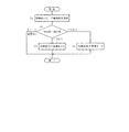
次に、第3実施例の作用について図18も参照して説明する。図18は、相関値算出部23による処理内容を示すフローチャートであるが、この処理については、ソフトウエア,ハードウエアの何れによって行っても良い。相関値算出部23は、先ず相関値のレベルがピークを示す間隔を検出すると(ステップS1)、今回の検出間隔と前回の検出間隔との差を求める(ステップS2)。そして、その差が「±3(サンプリング間隔)未満」であれば、そのまま処理を終了する。
一方、ステップS2において、検出間隔の差が「+3」以上であれば基準データ波形の周期を「+2」延長し(ステップS3)、検出間隔の差が「−3」以下であれば基準データ波形の周期を「−2」短縮する(ステップS4)。このように、基準データ波形の周期をダイナミックに変更することで、その周期が受信データ波形の周期よりも常に短くなるように制御する。
Next, the operation of the third embodiment will be described with reference to FIG. FIG. 18 is a flowchart showing the contents of processing by the correlation
On the other hand, in step S2, if the difference in detection interval is “+3” or more, the cycle of the reference data waveform is extended by “+2” (step S3), and if the difference in detection interval is “−3” or less, the reference data waveform. Is shortened by "-2" (step S4). Thus, by dynamically changing the cycle of the reference data waveform, the cycle is controlled so as to be always shorter than the cycle of the received data waveform.
以上のように第3実施例によれば、相関値算出部23は、相関値がピークを示す位置を検出してその検出間隔を求め、最新の検出間隔が前回よりも増加した場合は基準データの波形周期を延長し、最新の検出間隔が前回よりも減少した場合は基準データの波形周期を短縮するようにした。従って、受信データの通信レート変動が、どのような範囲で生じるのかが事前に把握できない場合であっても、その変動に追従して基準データの波形周期を変化させ、相関値のピークレベルが低下することを防止できる。
また、相関値算出部23は、基準データの波形周期を、最新の検出間隔よりも常に短くなるように変化させるので、ビットレートが変動した場合に相関値のピークが低下することをより確実に防止できる。そして、ビットレートの変動に追従して基準データの波形周期を変化させる制御を簡単に行うことができる。
As described above, according to the third embodiment, the correlation
In addition, since the correlation
本発明は上記し且つ図面に記載した実施例にのみ限定されるものではなく、以下のような変形が可能である。
想定される受信環境によっては受信信号のI系列,Q系列との何れか一方に基づいて、相関値と閾値とを算出しても良い。
閾値の算出周期は、より長い間隔で行うようにしても良い。
図10,図14に示す基準データ波形に対応する係数は、前半を「−1」,後半を「+1」にしても良い。
A/D変換部2のサンプリングレートが、以降のデータ処理を行うのに適切なレートである場合には、サンプリングレート変換部3を削除しても良い。
第2実施例における基準データのレベル変化比率は、適宜変更して実施すれば良い。また、図14に示す波形では、同一極性の範囲でレベルを3段階に変化させているが、1段階以上変化させれば良い。
The present invention is not limited to the embodiments described above and shown in the drawings, and the following modifications are possible.
Depending on the assumed reception environment, the correlation value and the threshold value may be calculated based on either the I-sequence or the Q-sequence of the received signal.
The threshold calculation cycle may be performed at longer intervals.
The coefficients corresponding to the reference data waveforms shown in FIGS. 10 and 14 may be “−1” in the first half and “+1” in the second half.
If the sampling rate of the A /
The level change ratio of the reference data in the second embodiment may be changed as appropriate. In the waveform shown in FIG. 14, the level is changed in three steps within the same polarity range, but may be changed in one step or more.
図面中、1は無線タグリーダ、3はサンプリングレート変換部(サンプリングレート設定手段)、5はIQ合成部、6は閾値算出部(閾値算出手段)、7は相関値算出部(相関値算出手段,マッチドフィルタ)、8はビット復号部(データ復号手段)、21は相関値算出部(相関値算出手段,マッチドフィルタ)、22は無線タグリーダ、23は相関値算出部(相関値算出手段,マッチドフィルタ,波形周期変化手段)を示す。 In the drawing, 1 is a wireless tag reader, 3 is a sampling rate conversion unit (sampling rate setting means), 5 is an IQ synthesis unit, 6 is a threshold value calculation unit (threshold value calculation unit), and 7 is a correlation value calculation unit (correlation value calculation unit, Matched filter), 8 is a bit decoding unit (data decoding unit), 21 is a correlation value calculation unit (correlation value calculation unit, matched filter), 22 is a wireless tag reader, 23 is a correlation value calculation unit (correlation value calculation unit, matched filter) , Waveform period changing means).
Claims (5)
前記受信信号に基づき、前記相関値についてデータビットを復号するための閾値を算出する閾値算出手段と、
前記相関値と閾値とに基づいてデータビットを復号するデータ復号手段とを備え、
前記閾値算出手段は、前記受信信号の振幅値を絶対値加算して平均値を算出すると、その平均値より得られる最大の相関値に基づいて正側閾値を算出し、その正側閾値の符号を反転させたものを負側閾値として設定し、
前記基準データは、前記受信信号について許容されている変動の下限周期を下回る周期で、且つ前記周期の中央で位相が180度変化する波形に設定されることを特徴とする無線タグリーダ。 Correlation value calculating means for calculating a correlation value between a sampling value of a data waveform demodulated by receiving a response signal from a wireless tag and reference data having a predetermined waveform pattern;
Threshold calculation means for calculating a threshold for decoding data bits for the correlation value based on the received signal;
Data decoding means for decoding data bits based on the correlation value and the threshold,
When the threshold value calculation means calculates the average value by adding the absolute values of the amplitude values of the received signals, the threshold value calculation means calculates the positive threshold value based on the maximum correlation value obtained from the average value, and the sign of the positive threshold value Is set as the negative threshold,
The wireless tag reader is characterized in that the reference data is set to a waveform having a period that is less than a lower limit period of variation allowed for the received signal and having a phase that changes by 180 degrees at the center of the period.
前記受信信号に基づき、前記相関値についてデータビットを復号するための閾値を算出する閾値算出手段と、
前記相関値と閾値とに基づいてデータビットを復号するデータ復号手段とを備え、
前記閾値算出手段は、前記受信信号の振幅値を絶対値加算して平均値を算出すると、その平均値より得られる最大の相関値に基づいて正側閾値を算出し、その正側閾値の符号を反転させたものを負側閾値として設定し、
前記基準データは、前記波形の周期中央で位相が180度変化すると共に、前記中央におけるレベルが最大に設定され、且つ同一極性を示す期間内でレベルが1段階以上変化する波形に設定されることを特徴とする無線タグリーダ。 Correlation value calculating means for calculating a correlation value between a sampling value of a data waveform demodulated by receiving a response signal from a wireless tag and reference data having a predetermined waveform pattern;
Threshold calculation means for calculating a threshold for decoding data bits for the correlation value based on the received signal;
Data decoding means for decoding data bits based on the correlation value and the threshold,
When the threshold value calculation means calculates the average value by adding the absolute values of the amplitude values of the received signals, the threshold value calculation means calculates the positive threshold value based on the maximum correlation value obtained from the average value, and the sign of the positive threshold value Is set as the negative threshold,
The reference data is set to a waveform in which the phase changes by 180 degrees at the center of the waveform period, the level at the center is set to the maximum, and the level changes by one or more steps within the period showing the same polarity. A wireless tag reader characterized by.
前記受信信号に基づき、前記相関値についてデータビットを復号するための閾値を算出する閾値算出手段と、
前記相関値と閾値とに基づいてデータビットを復号するデータ復号手段と、
前記相関値がピークを示す位置を検出してその検出間隔を求め、最新の検出間隔が前回よりも増加した場合は前記基準データの波形周期を延長し、最新の検出間隔が前回よりも減少した場合は前記基準データの波形周期を短縮する波形周期変化手段とを備え、
前記閾値算出手段は、前記受信信号の振幅値を絶対値加算して平均値を算出すると、その平均値より得られる最大の相関値に基づいて正側閾値を算出し、その正側閾値の符号を反転させたものを負側閾値として設定することを特徴とする無線タグリーダ。 Correlation value calculating means for calculating a correlation value between a sampling value of a data waveform demodulated by receiving a response signal from a wireless tag and reference data having a predetermined waveform pattern;
Threshold calculation means for calculating a threshold for decoding data bits for the correlation value based on the received signal;
Data decoding means for decoding data bits based on the correlation value and a threshold;
The position where the correlation value shows a peak is detected and its detection interval is obtained. When the latest detection interval is increased from the previous time, the waveform cycle of the reference data is extended, and the latest detection interval is decreased from the previous time. A waveform period changing means for shortening the waveform period of the reference data in the case,
When the threshold value calculation means calculates the average value by adding the absolute values of the amplitude values of the received signals, the threshold value calculation means calculates the positive threshold value based on the maximum correlation value obtained from the average value, and the sign of the positive threshold value A wireless tag reader characterized by setting a negative threshold as a negative threshold value.
Priority Applications (1)
| Application Number | Priority Date | Filing Date | Title |
|---|---|---|---|
| JP2007027951A JP4779986B2 (en) | 2007-02-07 | 2007-02-07 | Wireless tag reader |
Applications Claiming Priority (1)
| Application Number | Priority Date | Filing Date | Title |
|---|---|---|---|
| JP2007027951A JP4779986B2 (en) | 2007-02-07 | 2007-02-07 | Wireless tag reader |
Publications (2)
| Publication Number | Publication Date |
|---|---|
| JP2008193576A JP2008193576A (en) | 2008-08-21 |
| JP4779986B2 true JP4779986B2 (en) | 2011-09-28 |
Family
ID=39753209
Family Applications (1)
| Application Number | Title | Priority Date | Filing Date |
|---|---|---|---|
| JP2007027951A Expired - Fee Related JP4779986B2 (en) | 2007-02-07 | 2007-02-07 | Wireless tag reader |
Country Status (1)
| Country | Link |
|---|---|
| JP (1) | JP4779986B2 (en) |
Cited By (1)
| Publication number | Priority date | Publication date | Assignee | Title |
|---|---|---|---|---|
| JP2013521471A (en) * | 2010-02-25 | 2013-06-10 | クゥアルコム・インコーポレイテッド | Method and apparatus for applying a tactile pressure sensor |
Families Citing this family (4)
| Publication number | Priority date | Publication date | Assignee | Title |
|---|---|---|---|---|
| JP5312886B2 (en) * | 2008-09-22 | 2013-10-09 | 株式会社横須賀テレコムリサーチパーク | Encoding / decoding system, encoding circuit, decoding circuit, and tag communication apparatus |
| JP5240143B2 (en) * | 2009-09-16 | 2013-07-17 | 株式会社デンソーウェーブ | RFID reader / writer device |
| JP2012109894A (en) * | 2010-11-19 | 2012-06-07 | Renesas Electronics Corp | Receiver circuit |
| JP2023012092A (en) * | 2021-07-13 | 2023-01-25 | 東芝テック株式会社 | Tag reader apparatus |
-
2007
- 2007-02-07 JP JP2007027951A patent/JP4779986B2/en not_active Expired - Fee Related
Cited By (1)
| Publication number | Priority date | Publication date | Assignee | Title |
|---|---|---|---|---|
| JP2013521471A (en) * | 2010-02-25 | 2013-06-10 | クゥアルコム・インコーポレイテッド | Method and apparatus for applying a tactile pressure sensor |
Also Published As
| Publication number | Publication date |
|---|---|
| JP2008193576A (en) | 2008-08-21 |
Similar Documents
| Publication | Publication Date | Title |
|---|---|---|
| US7450666B2 (en) | Ask demodulation device and wireless device using the same | |
| JP4779986B2 (en) | Wireless tag reader | |
| EP2190157A2 (en) | Communication apparatus and signal processing method | |
| US10404448B2 (en) | Communication devices, method for detecting an edge in a received signal and method for receiving data | |
| JP3504119B2 (en) | Demodulation device, clock recovery device, demodulation method, and clock recovery method | |
| JP2008154285A (en) | Symbol timing detector, and wireless terminal | |
| US9722672B2 (en) | Wireless communication device and method of operating the same | |
| JP4609425B2 (en) | Wireless tag reader | |
| CN113438052B (en) | Signal decoding method, device, electronic equipment and storage medium | |
| CN110247734B (en) | Data transmission method and device and electronic equipment | |
| JP4268180B2 (en) | Symbol timing detection device and wireless terminal device | |
| JP4539392B2 (en) | Data reader | |
| JP5962987B2 (en) | Synchronization system, receiving device including the same, communication system including the same, and synchronization method | |
| CN107404452A (en) | BPSK demodulation methods and device, receiver | |
| JP4192110B2 (en) | DC offset calibration method and circuit for A / D converter | |
| JP4968910B2 (en) | Bit synchronization circuit | |
| US7999678B2 (en) | Demodulating module, RFID system utilizing the demodulating module and method thereof | |
| JP3478290B2 (en) | DUTY correction circuit | |
| KR100940830B1 (en) | Data receiving apparatus and receiving method thereof | |
| JP2010200220A (en) | Timing adjustment circuit, and method of adjusting the same | |
| CN109525531B (en) | Demodulation module, demodulation circuit and high-frequency card reader | |
| KR101011496B1 (en) | Miller decoding circuit and method thereof | |
| JP2008283634A (en) | Demodulation circuit and rfid system | |
| KR19990085246A (en) | Apparatus and method for reducing pattern jitter using local symmetric forced waveform | |
| JP3458782B2 (en) | DUTY correction circuit |
Legal Events
| Date | Code | Title | Description |
|---|---|---|---|
| A621 | Written request for application examination |
Free format text: JAPANESE INTERMEDIATE CODE: A621 Effective date: 20090130 |
|
| A977 | Report on retrieval |
Free format text: JAPANESE INTERMEDIATE CODE: A971007 Effective date: 20101227 |
|
| TRDD | Decision of grant or rejection written | ||
| A01 | Written decision to grant a patent or to grant a registration (utility model) |
Free format text: JAPANESE INTERMEDIATE CODE: A01 Effective date: 20110607 |
|
| A01 | Written decision to grant a patent or to grant a registration (utility model) |
Free format text: JAPANESE INTERMEDIATE CODE: A01 |
|
| A61 | First payment of annual fees (during grant procedure) |
Free format text: JAPANESE INTERMEDIATE CODE: A61 Effective date: 20110620 |
|
| FPAY | Renewal fee payment (event date is renewal date of database) |
Free format text: PAYMENT UNTIL: 20140715 Year of fee payment: 3 |
|
| R150 | Certificate of patent or registration of utility model |
Ref document number: 4779986 Country of ref document: JP Free format text: JAPANESE INTERMEDIATE CODE: R150 Free format text: JAPANESE INTERMEDIATE CODE: R150 |
|
| FPAY | Renewal fee payment (event date is renewal date of database) |
Free format text: PAYMENT UNTIL: 20140715 Year of fee payment: 3 |
|
| R250 | Receipt of annual fees |
Free format text: JAPANESE INTERMEDIATE CODE: R250 |
|
| R250 | Receipt of annual fees |
Free format text: JAPANESE INTERMEDIATE CODE: R250 |
|
| R250 | Receipt of annual fees |
Free format text: JAPANESE INTERMEDIATE CODE: R250 |
|
| R250 | Receipt of annual fees |
Free format text: JAPANESE INTERMEDIATE CODE: R250 |
|
| R250 | Receipt of annual fees |
Free format text: JAPANESE INTERMEDIATE CODE: R250 |
|
| R250 | Receipt of annual fees |
Free format text: JAPANESE INTERMEDIATE CODE: R250 |
|
| LAPS | Cancellation because of no payment of annual fees |